EP2703020B2 - Injection device for performing medical injections - Google Patents
Injection device for performing medical injections Download PDFInfo
- Publication number
- EP2703020B2 EP2703020B2 EP13183809.6A EP13183809A EP2703020B2 EP 2703020 B2 EP2703020 B2 EP 2703020B2 EP 13183809 A EP13183809 A EP 13183809A EP 2703020 B2 EP2703020 B2 EP 2703020B2
- Authority
- EP
- European Patent Office
- Prior art keywords
- piston rod
- foot
- plunger
- injection device
- cartridge
- Prior art date
- Legal status (The legal status is an assumption and is not a legal conclusion. Google has not performed a legal analysis and makes no representation as to the accuracy of the status listed.)
- Active
Links
- 238000002347 injection Methods 0.000 title claims description 95
- 239000007924 injection Substances 0.000 title claims description 95
- 238000010999 medical injection Methods 0.000 title claims description 4
- 239000003814 drug Substances 0.000 claims description 20
- 229940079593 drug Drugs 0.000 claims description 17
- 239000007788 liquid Substances 0.000 claims description 17
- 238000000034 method Methods 0.000 claims description 15
- 239000012528 membrane Substances 0.000 claims description 9
- NOESYZHRGYRDHS-UHFFFAOYSA-N insulin Chemical compound N1C(=O)C(NC(=O)C(CCC(N)=O)NC(=O)C(CCC(O)=O)NC(=O)C(C(C)C)NC(=O)C(NC(=O)CN)C(C)CC)CSSCC(C(NC(CO)C(=O)NC(CC(C)C)C(=O)NC(CC=2C=CC(O)=CC=2)C(=O)NC(CCC(N)=O)C(=O)NC(CC(C)C)C(=O)NC(CCC(O)=O)C(=O)NC(CC(N)=O)C(=O)NC(CC=2C=CC(O)=CC=2)C(=O)NC(CSSCC(NC(=O)C(C(C)C)NC(=O)C(CC(C)C)NC(=O)C(CC=2C=CC(O)=CC=2)NC(=O)C(CC(C)C)NC(=O)C(C)NC(=O)C(CCC(O)=O)NC(=O)C(C(C)C)NC(=O)C(CC(C)C)NC(=O)C(CC=2NC=NC=2)NC(=O)C(CO)NC(=O)CNC2=O)C(=O)NCC(=O)NC(CCC(O)=O)C(=O)NC(CCCNC(N)=N)C(=O)NCC(=O)NC(CC=3C=CC=CC=3)C(=O)NC(CC=3C=CC=CC=3)C(=O)NC(CC=3C=CC(O)=CC=3)C(=O)NC(C(C)O)C(=O)N3C(CCC3)C(=O)NC(CCCCN)C(=O)NC(C)C(O)=O)C(=O)NC(CC(N)=O)C(O)=O)=O)NC(=O)C(C(C)CC)NC(=O)C(CO)NC(=O)C(C(C)O)NC(=O)C1CSSCC2NC(=O)C(CC(C)C)NC(=O)C(NC(=O)C(CCC(N)=O)NC(=O)C(CC(N)=O)NC(=O)C(NC(=O)C(N)CC=1C=CC=CC=1)C(C)C)CC1=CN=CN1 NOESYZHRGYRDHS-UHFFFAOYSA-N 0.000 description 13
- 102000004877 Insulin Human genes 0.000 description 6
- 108090001061 Insulin Proteins 0.000 description 6
- 229940125396 insulin Drugs 0.000 description 6
- 238000003466 welding Methods 0.000 description 4
- 230000002427 irreversible effect Effects 0.000 description 3
- 230000037452 priming Effects 0.000 description 3
- 108010026951 Short-Acting Insulin Proteins 0.000 description 2
- 206010012601 diabetes mellitus Diseases 0.000 description 2
- 239000011521 glass Substances 0.000 description 2
- 239000000463 material Substances 0.000 description 2
- 238000002844 melting Methods 0.000 description 2
- 230000008018 melting Effects 0.000 description 2
- 229920000642 polymer Polymers 0.000 description 2
- 108090000623 proteins and genes Proteins 0.000 description 2
- 239000000243 solution Substances 0.000 description 2
- VOUAQYXWVJDEQY-QENPJCQMSA-N 33017-11-7 Chemical compound OC(=O)CC[C@H](N)C(=O)N[C@@H](C)C(=O)N[C@@H](CCC(O)=O)C(=O)N[C@@H](CC(O)=O)C(=O)N[C@@H](CC(C)C)C(=O)N[C@@H](CCC(N)=O)C(=O)N[C@@H](C(C)C)C(=O)NCC(=O)N[C@@H](CCC(N)=O)C(=O)N[C@@H](C(C)C)C(=O)N[C@@H](CCC(O)=O)C(=O)N[C@@H](CC(C)C)C(=O)NCC(=O)NCC(=O)NCC(=O)N1CCC[C@H]1C(=O)NCC(=O)N[C@@H](C)C(=O)NCC(=O)N[C@@H](CO)C(=O)N[C@@H](CC(C)C)C(=O)N[C@@H](CCC(N)=O)C(=O)N1[C@H](C(=O)N[C@@H](CC(C)C)C(=O)N[C@@H](C)C(=O)N[C@@H](CC(C)C)C(=O)N[C@@H](CCC(O)=O)C(=O)NCC(=O)N[C@@H](CO)C(=O)N[C@@H](CC(C)C)C(=O)N[C@@H](CCC(N)=O)C(O)=O)CCC1 VOUAQYXWVJDEQY-QENPJCQMSA-N 0.000 description 1
- 108010075254 C-Peptide Proteins 0.000 description 1
- 102000016261 Long-Acting Insulin Human genes 0.000 description 1
- 108010092217 Long-Acting Insulin Proteins 0.000 description 1
- 229940100066 Long-acting insulin Drugs 0.000 description 1
- 229940123452 Rapid-acting insulin Drugs 0.000 description 1
- 229940123958 Short-acting insulin Drugs 0.000 description 1
- 239000013543 active substance Substances 0.000 description 1
- 238000004026 adhesive bonding Methods 0.000 description 1
- 239000003708 ampul Substances 0.000 description 1
- 239000003795 chemical substances by application Substances 0.000 description 1
- 230000008878 coupling Effects 0.000 description 1
- 238000010168 coupling process Methods 0.000 description 1
- 238000005859 coupling reaction Methods 0.000 description 1
- 230000003247 decreasing effect Effects 0.000 description 1
- 230000009969 flowable effect Effects 0.000 description 1
- 239000012530 fluid Substances 0.000 description 1
- 230000006870 function Effects 0.000 description 1
- 239000000499 gel Substances 0.000 description 1
- 230000014509 gene expression Effects 0.000 description 1
- 239000003292 glue Substances 0.000 description 1
- 230000003054 hormonal effect Effects 0.000 description 1
- 229940088597 hormone Drugs 0.000 description 1
- 239000005556 hormone Substances 0.000 description 1
- 238000010348 incorporation Methods 0.000 description 1
- 238000004519 manufacturing process Methods 0.000 description 1
- 235000012054 meals Nutrition 0.000 description 1
- 239000000155 melt Substances 0.000 description 1
- 239000007769 metal material Substances 0.000 description 1
- 238000012986 modification Methods 0.000 description 1
- 230000004048 modification Effects 0.000 description 1
- 235000016709 nutrition Nutrition 0.000 description 1
- 230000037368 penetrate the skin Effects 0.000 description 1
- 230000035515 penetration Effects 0.000 description 1
- 102000004196 processed proteins & peptides Human genes 0.000 description 1
- 108090000765 processed proteins & peptides Proteins 0.000 description 1
- 102000004169 proteins and genes Human genes 0.000 description 1
- 239000007787 solid Substances 0.000 description 1
- 229910001220 stainless steel Inorganic materials 0.000 description 1
- 239000010935 stainless steel Substances 0.000 description 1
- 238000007920 subcutaneous administration Methods 0.000 description 1
- 239000000126 substance Substances 0.000 description 1
- 239000000725 suspension Substances 0.000 description 1
- 239000012815 thermoplastic material Substances 0.000 description 1
Images


Classifications
-
- A—HUMAN NECESSITIES
- A61—MEDICAL OR VETERINARY SCIENCE; HYGIENE
- A61M—DEVICES FOR INTRODUCING MEDIA INTO, OR ONTO, THE BODY; DEVICES FOR TRANSDUCING BODY MEDIA OR FOR TAKING MEDIA FROM THE BODY; DEVICES FOR PRODUCING OR ENDING SLEEP OR STUPOR
- A61M5/00—Devices for bringing media into the body in a subcutaneous, intra-vascular or intramuscular way; Accessories therefor, e.g. filling or cleaning devices, arm-rests
- A61M5/178—Syringes
- A61M5/31—Details
- A61M5/3129—Syringe barrels
-
- A—HUMAN NECESSITIES
- A61—MEDICAL OR VETERINARY SCIENCE; HYGIENE
- A61M—DEVICES FOR INTRODUCING MEDIA INTO, OR ONTO, THE BODY; DEVICES FOR TRANSDUCING BODY MEDIA OR FOR TAKING MEDIA FROM THE BODY; DEVICES FOR PRODUCING OR ENDING SLEEP OR STUPOR
- A61M5/00—Devices for bringing media into the body in a subcutaneous, intra-vascular or intramuscular way; Accessories therefor, e.g. filling or cleaning devices, arm-rests
- A61M5/178—Syringes
- A61M5/24—Ampoule syringes, i.e. syringes with needle for use in combination with replaceable ampoules or carpules, e.g. automatic
-
- A—HUMAN NECESSITIES
- A61—MEDICAL OR VETERINARY SCIENCE; HYGIENE
- A61M—DEVICES FOR INTRODUCING MEDIA INTO, OR ONTO, THE BODY; DEVICES FOR TRANSDUCING BODY MEDIA OR FOR TAKING MEDIA FROM THE BODY; DEVICES FOR PRODUCING OR ENDING SLEEP OR STUPOR
- A61M5/00—Devices for bringing media into the body in a subcutaneous, intra-vascular or intramuscular way; Accessories therefor, e.g. filling or cleaning devices, arm-rests
- A61M5/178—Syringes
- A61M5/31—Details
- A61M5/3146—Priming, e.g. purging, reducing backlash or clearance
-
- A—HUMAN NECESSITIES
- A61—MEDICAL OR VETERINARY SCIENCE; HYGIENE
- A61M—DEVICES FOR INTRODUCING MEDIA INTO, OR ONTO, THE BODY; DEVICES FOR TRANSDUCING BODY MEDIA OR FOR TAKING MEDIA FROM THE BODY; DEVICES FOR PRODUCING OR ENDING SLEEP OR STUPOR
- A61M5/00—Devices for bringing media into the body in a subcutaneous, intra-vascular or intramuscular way; Accessories therefor, e.g. filling or cleaning devices, arm-rests
- A61M5/178—Syringes
- A61M5/31—Details
- A61M5/315—Pistons; Piston-rods; Guiding, blocking or restricting the movement of the rod or piston; Appliances on the rod for facilitating dosing ; Dosing mechanisms
- A61M5/31511—Piston or piston-rod constructions, e.g. connection of piston with piston-rod
- A61M5/31515—Connection of piston with piston rod
-
- A—HUMAN NECESSITIES
- A61—MEDICAL OR VETERINARY SCIENCE; HYGIENE
- A61M—DEVICES FOR INTRODUCING MEDIA INTO, OR ONTO, THE BODY; DEVICES FOR TRANSDUCING BODY MEDIA OR FOR TAKING MEDIA FROM THE BODY; DEVICES FOR PRODUCING OR ENDING SLEEP OR STUPOR
- A61M5/00—Devices for bringing media into the body in a subcutaneous, intra-vascular or intramuscular way; Accessories therefor, e.g. filling or cleaning devices, arm-rests
- A61M5/178—Syringes
- A61M5/24—Ampoule syringes, i.e. syringes with needle for use in combination with replaceable ampoules or carpules, e.g. automatic
- A61M2005/2403—Ampoule inserted into the ampoule holder
- A61M2005/2407—Ampoule inserted into the ampoule holder from the rear
-
- A—HUMAN NECESSITIES
- A61—MEDICAL OR VETERINARY SCIENCE; HYGIENE
- A61M—DEVICES FOR INTRODUCING MEDIA INTO, OR ONTO, THE BODY; DEVICES FOR TRANSDUCING BODY MEDIA OR FOR TAKING MEDIA FROM THE BODY; DEVICES FOR PRODUCING OR ENDING SLEEP OR STUPOR
- A61M5/00—Devices for bringing media into the body in a subcutaneous, intra-vascular or intramuscular way; Accessories therefor, e.g. filling or cleaning devices, arm-rests
- A61M5/178—Syringes
- A61M5/24—Ampoule syringes, i.e. syringes with needle for use in combination with replaceable ampoules or carpules, e.g. automatic
- A61M2005/2485—Ampoule holder connected to rest of syringe
- A61M2005/2488—Ampoule holder connected to rest of syringe via rotation, e.g. threads or bayonet
-
- A—HUMAN NECESSITIES
- A61—MEDICAL OR VETERINARY SCIENCE; HYGIENE
- A61M—DEVICES FOR INTRODUCING MEDIA INTO, OR ONTO, THE BODY; DEVICES FOR TRANSDUCING BODY MEDIA OR FOR TAKING MEDIA FROM THE BODY; DEVICES FOR PRODUCING OR ENDING SLEEP OR STUPOR
- A61M2207/00—Methods of manufacture, assembly or production
Definitions
- the invention relates to a variable connection for an injection device and preferably for a variable connection between the parts of an injection device determining the distance between the movable element in the container and the part moving the movable part.
- People suffering from diabetes are often treated with multiple daily injections in a regimen comprising one or two daily injections of a long acting insulin to cover the basal requirement supplemented by bolus injections of a short or rapid acting insulin to cover requirements related to meals.
- the first type of system being injection devices with a replaceable cartridge containing the insulin to be injected. Often such cartridges contain 3 ml of insulin, and when this amount has been injected a new cartridge is inserted in the same injection device which therefore often is in use for several years. Such injections devices are usually referred to durable injection devices.
- injection devices containing a predetermined and non-replaceable amount of insulin, also often 3 ml.
- the insulin is often contained in a cartridge embedded in the injection device.
- the predetermined amount has been injected which can take anywhere from a few days to a month, the entire injection device is discarded and a new injection device is used for subsequent injections.
- Such injection devices are often referred to as disposable or prefilled injection pens.
- the present invention lies within this type of injection devices.
- the tolerances When clicking the parts of an injection device together the tolerances must be calculated such that the click- or snap function will always be activated i.e. the tolerances must be such that the "point of no return" is always reached during assembly otherwise the injection device will fall apart.
- the distal end of the piston rod means must not be pressed against the plunger while this will pressurize the content in the cartridge with the result that the liquid drug will start to flow from the injection device once an injection needle is mounted to the needle mount.
- the assembled injection device will always be delivered to its final user with a distance between the plunger and the distal end of the piston rod means, a distance that will vary for each single injection device.
- the user must therefore make an initial priming of the injection device before first use i.e. the user must perform one or more air shoots before the first use of the device such that the distal end of the piston rod means are moved into abutment with the rubber plunger.
- the device By determining the distance between the distal end of the piston rod means and the plunger of the cartridge individually during assembly, the device can be assembled such that this distance is minimized, preferably minimized to zero such that the piston rod means abuts the plunger.
- the individual adjustment of this distance can be practised in many different ways, one way could be to have the piston rod means comprise two parts which can be adjusted relative to each other in the axial direction during assembly.
- the piston rod means could e.g. be made from a piston rod and a piston rod foot which has an interface that can slide axially. Once the piston rod and the piston rod foot are slid into the correct position the two elements are permanently connected to each other, preferably by welding.
- the piston rod foot is provided with a number of wings that engages a number of recesses in the piston rod, which recesses preferably has a sloping configuration such that the piston rod foot is urged in the distal direction.
- the dose setting and injection mechanism comprises the piston rod and the container comprises a plunger, and the distance between these two parts are, according to the invention sought minimized.
- the method comprises the steps of:
- the piston rod means can be telescopic and locked together during the assembly.
- the system that makes up a prefilled injection device usually comprises two parts, a dose setting and injection mechanism which are contained in a first body part of the housing and a cartridge which is embedded in a second body part of the housing, often referred to as the cartridge holder.
- this system further comprises means for varying the distance between the piston rod means of the dose setting and injection part and the plunger of the cartridge holder part.
- injection pen is typically an injection apparatus having an oblong or elongated shape somewhat like a pen for writing. Although such pens usually have a tubular cross-section, they could easily have a different cross-section such as triangular, rectangular or square or any variation around these geometries.
- drug is meant to encompass any drug-containing flowable medicine capable of being passed through a delivery means such as a hollow needle in a controlled manner, such as a liquid, solution, gel or fine suspension.
- a delivery means such as a hollow needle in a controlled manner, such as a liquid, solution, gel or fine suspension.
- Representative drugs includes pharmaceuticals such as peptides, proteins (e.g. insulin, insulin analogues and C-peptide), and hormones, biologically derived or active agents, hormonal and gene based agents, nutritional formulas and other substances in both solid (dispensed) or liquid form.
- subcutaneous injection is meant to encompass any method of transcutaneous delivery to a subject.
- injection needle defines a piercing member adapted to penetrate the skin of a subject for the purpose of delivering or removing a liquid.
- An “injection needle” usually comprises a “needle cannula” and a “hub”.
- the term “Needle Cannula” is used to describe the actual conduit performing the penetration of the skin during injection.
- a needle cannula is usually made from a metallic material such as stainless steel and connected to a hub to form an injection needle assembly.
- a needle cannula could however also be made from a polymeric material or a glass material.
- the "hub” being the part in which the needle cannula is mounted carries the connecting means for connecting the needle cannula to an injection apparatus.
- a hub is usually moulded from a suitable thermoplastic material.
- An “injection needle” is also sometime referred as a "needle assembly” i.e. comprising a needle cannula mounted in a hub as supplied to the user.
- Cartridge is the term used to describe the container containing the liquid drug e.g. insulin. Cartridges are usually made from glass but could also be moulded from any suitable polymer.
- a cartridge or ampoule is preferably sealed at one end by a pierceable membrane which can be pierced e.g. by an injection needle. The opposite end is closed by a plunger made from rubber or a suitable polymer. The plunger can be slidable moved inside the cartridge. The space between the pierceable membrane and the movable plunger holds the liquid drug which is pressed out as the plunger decreased the volume of the space holding the liquid drug.
- Pimal rod means is the term used to describe the mechanical element that transfer force from the dosing mechanism to the plunger inside the cartridge thereby moving the plunger forward.
- the “piston rod means” usually comprises a piston rod and a piston rod foot which is typically the element abutting the plunger.
- the piston rod and the piston rod foot can be made as two separate pieces or they can be made as one integral element.
- the “piston rod means” could also only be the piston rod without any foot in which case the piston rod would abut directly on the plunger.
- distal end in the appended figures is meant to refer to the end of the injection device carrying the injection needle whereas the term “proximal end” is meant to refer to the opposite end pointing away from the injection needle.
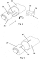
- Figure 1 discloses a pen shaped injection device 1 comprising a housing 10 formed from two parts 20, 30.
- a first part 20 holding the cartridge 40 and a second part 30 comprising a dose setting and injection mechanism which comprises a piston rod means 50.
- the cartridge 40 which contains the liquid medicament to be expelled is at a first end 41 provided with a membrane 42 which is pierceable by a not shown injection needle and a second end 43 which is locked by a movable plunger 44.
- the first part 20 is at its proximal end provided with a number of outwardly pointing ratchet teeth 21 which as disclosed in figure 2 can surround the entire periphery of the first part 20.
- the second part 30 is at its distal end provided with corresponding inwardly pointing ratchet teeth 31.
- the teeth 21, 31, could be provided only on a part of the periphery.
- the outwardly pointing ratchet teeth 21 engage the inwardly pointing ratchet teeth 31 on the second part 30 thereby preventing the two part 20, 30 from being separated.
- the two parts 20, 30 can be variable adjusted relatively to each other such that the distance X between the piston rod means 50 and the plunger 44 can be minimized.
- the two parts 20, 30 can be irreversible locked to each other. This irreversible locking can be performed in a number of different ways.
- the two parts 20, 30 are permanently secured to each other by deforming zones 32 of the second part 30. This deformation can be done by pressure or by heat deformation.
- a solution based on a counter nut 60 is disclosed in figure 3 .
- the first part 20 and the second part 30 is provided with engaging threads 22, 33 such that the two parts 20, 30 are moved closer to each other when rotated.
- the counter nut 60 is screwed in the distal direction until it abuts the first part 20 thereby locking the two parts20, 30 together.
- the first part 20 is provided with a number of outwardly pointing protrusions 23 and the second part 30 is provided with a number of axially located ribs 34.
- the protrusions 23 penetrate through the ribs 34 as disclosed in the close-up figure, thereby locking the two parts 20, 30 to each other.
- the first part 20 is provided with an axially extending rib 24 which during assembly engages a longitudinal slit 35 in the second part.
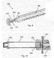
- the piston rod means 150 comprises a piston rod 160 and a piston rod foot 170.
- the piston rod foot 170 is provided with a number of resilient attaching wings 171 pointing in the proximal direction and the piston rod 160 is provided with a number of recesses 161 for receiving the attaching wings 171.
- These recesses 161 have a sloping configuration sloping towards the distal end of the piston rod 160 such that the piston rod foot 170 will slide in the proximal direction when the piston rod foot 170 is mounted on the piston rod 160. Further the piston rod 160 is provided with a number of protrusions 162 engaging a number of barbs 172 on the piston rod foot 170 when it is in its most distal position thereby preventing the piston rod foot 170 from being automatically separated from the piston rod 160.
- the cartridge holder 20, 120 could in all the embodiments be provided with an opening or window as indicated in figure 4, 5 and 10 through which the liquid drug in the cartridge 40, 140 can be viewed.
- the piston foot 170 When an injection device is assembled the piston foot 170 is axially pushed onto the piston rod 160 as disclosed in figure 6 to 9 . Once the correct relative position between the piston rod foot 170 and the piston rod 160 is obtained a laser beam 180 is directed towards the attaching wings 171 such that a melting zone 181 between the attaching wings 171 of the piston rod foot 170 and the recesses 161 of the piston rod 161 is obtained thereby melting the piston rod foot 170 and the piston rod 160 together.
- laser welding is described in this application a number of alternative methods for attaching the two parts 160, 170 can be used.
- the piston rod foot 170 and the piston rod 160 could e.g. be attached to each other through a variable mechanical connection such as a threaded connection or a telescopic mechanism; alternatively the two parts 160, 170 could be glued together in their final position.
Landscapes
- Health & Medical Sciences (AREA)
- Vascular Medicine (AREA)
- Engineering & Computer Science (AREA)
- Anesthesiology (AREA)
- Biomedical Technology (AREA)
- Heart & Thoracic Surgery (AREA)
- Hematology (AREA)
- Life Sciences & Earth Sciences (AREA)
- Animal Behavior & Ethology (AREA)
- General Health & Medical Sciences (AREA)
- Public Health (AREA)
- Veterinary Medicine (AREA)
- Infusion, Injection, And Reservoir Apparatuses (AREA)
Description
- The invention relates to a variable connection for an injection device and preferably for a variable connection between the parts of an injection device determining the distance between the movable element in the container and the part moving the movable part.
- People suffering from diabetes are often treated with multiple daily injections in a regimen comprising one or two daily injections of a long acting insulin to cover the basal requirement supplemented by bolus injections of a short or rapid acting insulin to cover requirements related to meals.
- Generally speaking two different types of pen systems are used for the treatment of diabetes. The first type of system being injection devices with a replaceable cartridge containing the insulin to be injected. Often such cartridges contain 3 ml of insulin, and when this amount has been injected a new cartridge is inserted in the same injection device which therefore often is in use for several years. Such injections devices are usually referred to durable injection devices.
- An example of such durable injection device where the cartridge is connected to the injection device by way of a bayonet coupling is e.g. disclosed in
WO 99/16487 - The other type being injection devices containing a predetermined and non-replaceable amount of insulin, also often 3 ml. The insulin is often contained in a cartridge embedded in the injection device. When the predetermined amount has been injected which can take anywhere from a few days to a month, the entire injection device is discarded and a new injection device is used for subsequent injections. Such injection devices are often referred to as disposable or prefilled injection pens. The present invention lies within this type of injection devices.
- An example of such prefilled injection pen where the two parts forming the housing is irreversible clicked together thereby encapsulating the container is known from
US 6,004,297 and fromWO 2008/003560 . - A further example of prior art injection devices is given in
GB 806 703 A - When clicking the parts of an injection device together the tolerances must be calculated such that the click- or snap function will always be activated i.e. the tolerances must be such that the "point of no return" is always reached during assembly otherwise the injection device will fall apart. At the same time the distal end of the piston rod means must not be pressed against the plunger while this will pressurize the content in the cartridge with the result that the liquid drug will start to flow from the injection device once an injection needle is mounted to the needle mount.
- Not only does the individual parts making up the injection device come with certain tolerances, also when filing the liquid drug into the cartridge a certain tolerance obliges, both in regard of the cartridge itself and in regard of the volume of the content, which results in a slightly different position of the plunger from one cartridge to another.
- Due to these production tolerances there must always be sufficient space between the plunger of the cartridge and the distal end of the piston rod means of the dose setting and injection mechanism to absorb the tolerances and to allow the "point of no return" to be reached during the assembly of the injection device in all cases.
- As a result of this the assembled injection device will always be delivered to its final user with a distance between the plunger and the distal end of the piston rod means, a distance that will vary for each single injection device. The user must therefore make an initial priming of the injection device before first use i.e. the user must perform one or more air shoots before the first use of the device such that the distal end of the piston rod means are moved into abutment with the rubber plunger.
- For injection devices operating with large dose sizes this is critical, since the air shoots are based on the large dose size. When the user executes the last air shoot bringing the piston rod means into abutment with the plunger this shoot can be larger than the remaining distance between the piston rod means and the plunger resulting in a forward movement of the plunger and a significant loss of fluid drug.
- It is an object of the present invention to provide an injection device in which initial priming can be avoided.
- By determining the distance between the distal end of the piston rod means and the plunger of the cartridge individually during assembly, the device can be assembled such that this distance is minimized, preferably minimized to zero such that the piston rod means abuts the plunger. The individual adjustment of this distance can be practised in many different ways, one way could be to have the piston rod means comprise two parts which can be adjusted relative to each other in the axial direction during assembly.
- The piston rod means could e.g. be made from a piston rod and a piston rod foot which has an interface that can slide axially. Once the piston rod and the piston rod foot are slid into the correct position the two elements are permanently connected to each other, preferably by welding.
- In one embodiment the piston rod foot is provided with a number of wings that engages a number of recesses in the piston rod, which recesses preferably has a sloping configuration such that the piston rod foot is urged in the distal direction.
- The dose setting and injection mechanism comprises the piston rod and the container comprises a plunger, and the distance between these two parts are, according to the invention sought minimized.
- when the axial distance is based on a relative axial movement between the parts making up the piston rod means, the method comprises the steps of:
- (i) Bringing the piston rod means in abutment with the plunger,
- (ii) Securing the piston rod means in this position.
- As an alternative to providing the relative axial movement between the piston rod and the piston rod foot, the piston rod means can be telescopic and locked together during the assembly.
- The system that makes up a prefilled injection device usually comprises two parts, a dose setting and injection mechanism which are contained in a first body part of the housing and a cartridge which is embedded in a second body part of the housing, often referred to as the cartridge holder.
- According to the present invention this system further comprises means for varying the distance between the piston rod means of the dose setting and injection part and the plunger of the cartridge holder part.
- These means can be provided in the piston rod means such as between the piston rod and the piston rod foot.
- These detailed described embodiments do not exclude other ways of incorporating the means for varying the distance in an injection device.
- An "injection pen" is typically an injection apparatus having an oblong or elongated shape somewhat like a pen for writing. Although such pens usually have a tubular cross-section, they could easily have a different cross-section such as triangular, rectangular or square or any variation around these geometries.
- As used herein, the term "drug" is meant to encompass any drug-containing flowable medicine capable of being passed through a delivery means such as a hollow needle in a controlled manner, such as a liquid, solution, gel or fine suspension. Representative drugs includes pharmaceuticals such as peptides, proteins (e.g. insulin, insulin analogues and C-peptide), and hormones, biologically derived or active agents, hormonal and gene based agents, nutritional formulas and other substances in both solid (dispensed) or liquid form.
- Correspondingly, the term "subcutaneous" injection is meant to encompass any method of transcutaneous delivery to a subject.
- Further the term "injection needle" defines a piercing member adapted to penetrate the skin of a subject for the purpose of delivering or removing a liquid. An "injection needle" usually comprises a "needle cannula" and a "hub". The term "Needle Cannula" is used to describe the actual conduit performing the penetration of the skin during injection. A needle cannula is usually made from a metallic material such as stainless steel and connected to a hub to form an injection needle assembly. A needle cannula could however also be made from a polymeric material or a glass material. The "hub" being the part in which the needle cannula is mounted carries the connecting means for connecting the needle cannula to an injection apparatus. A hub is usually moulded from a suitable thermoplastic material. An "injection needle" is also sometime referred as a "needle assembly" i.e. comprising a needle cannula mounted in a hub as supplied to the user.
- "Cartridge" is the term used to describe the container containing the liquid drug e.g. insulin. Cartridges are usually made from glass but could also be moulded from any suitable polymer. A cartridge or ampoule is preferably sealed at one end by a pierceable membrane which can be pierced e.g. by an injection needle. The opposite end is closed by a plunger made from rubber or a suitable polymer. The plunger can be slidable moved inside the cartridge. The space between the pierceable membrane and the movable plunger holds the liquid drug which is pressed out as the plunger decreased the volume of the space holding the liquid drug.
- "Piston rod means" is the term used to describe the mechanical element that transfer force from the dosing mechanism to the plunger inside the cartridge thereby moving the plunger forward. The "piston rod means" usually comprises a piston rod and a piston rod foot which is typically the element abutting the plunger. The piston rod and the piston rod foot can be made as two separate pieces or they can be made as one integral element. The "piston rod means" could also only be the piston rod without any foot in which case the piston rod would abut directly on the plunger.
- All references, including publications, patent applications, and patents, cited herein are incorporated by reference in their entirety and to the same extent as if each reference were individually and specifically indicated to be incorporated by reference and were set forth in its entirety herein.
All headings and sub-headings are used herein for convenience only and should not be constructed as limiting the invention in any way.
The use of any and all examples, or exemplary language (e.g. such as) provided herein, is intended merely to better illuminate the invention and does not pose a limitation on the scope of the invention unless otherwise claimed. No language in the specification should be construed as indicating any non-claimed element as essential to the practice of the invention. The citation and incorporation of patent documents herein is done for convenience only and does not reflect any view of the validity, patentability, and/or enforceability of such patent documents. - This invention includes all modifications and equivalents of the subject matter recited in the claims appended hereto as permitted by applicable law.
- The invention will be explained more fully below in connection with a preferred embodiment and with reference to the drawings in which
Figs. 1-5 show an example which is not part of the presently claimed invention: - Figure 1
- shows a cross section of the injection device.
- Figure 2
- shows a perspective view of an assembly of the housing.
- Figure 3
- shows a cross sectional view of an alternatively assembly of the housing.
- Figure 4
- shows a perspective view of an alternatively assembly of the housing.
- Figure 5
- shows a perspective view of an alternatively assembly of the housing.
- Figure 6
- shows a cross sectional view of the piston rod means prior to assembly.
- Figure 7
- shows a cross sectional view of the piston rod means in one assembled position.
- Figure 8
- shows a cross sectional view of the piston rod means in a different assembled position.
- Figure 9
- shows a view of the piston rod means.
- Figure 10
- show a cross section of the injection device during assembly.
- The figures are schematic and simplified for clarity, and they just show details, which are essential to the understanding of the invention, while other details are left out. Throughout, the same reference numerals are used for identical or corresponding parts.
- When in the following terms as "upper" and "lower", "right" and "left", "horizontal" and "vertical", "clockwise" and "counter clockwise" or similar relative expressions are used, these only refer to the appended figures and not to an actual situation of use. The shown figures are schematic representations for which reason the configuration of the different structures as well as there relative dimensions are intended to serve illustrative purposes only.
- In that context it may be convenient to define that the term "distal end" in the appended figures is meant to refer to the end of the injection device carrying the injection needle whereas the term "proximal end" is meant to refer to the opposite end pointing away from the injection needle.
-
Figure 1 discloses a pen shaped injection device 1 comprising ahousing 10 formed from twoparts first part 20 holding thecartridge 40 and asecond part 30 comprising a dose setting and injection mechanism which comprises a piston rod means 50. - The
cartridge 40 which contains the liquid medicament to be expelled is at afirst end 41 provided with amembrane 42 which is pierceable by a not shown injection needle and asecond end 43 which is locked by amovable plunger 44. When a user activates the dose setting and injection mechanism to set and inject a dose, the piston rod means 50 is moved forward into contact with theplunger 44 which it then continues to move forward thereby expelling the set dose through the injection needle. - The
first part 20 is at its proximal end provided with a number of outwardly pointing ratchetteeth 21 which as disclosed infigure 2 can surround the entire periphery of thefirst part 20. Thesecond part 30 is at its distal end provided with corresponding inwardly pointingratchet teeth 31. Instead of providing the inwardly pointingratchet teeth 31 and the outwardly pointing ratchetteeth 21 around the entire periphery, theteeth - When the proximal end of the
first part 20 enters the distal end of thesecond part 30 in order to assemble thehousing 10, the outwardly pointing ratchetteeth 21 engage the inwardly pointingratchet teeth 31 on thesecond part 30 thereby preventing the twopart parts plunger 44 can be minimized. - Once the
first part 20 and thesecond part 30 is in a position where a satisfactory distance X is obtained the twoparts - In
figure 2 the twoparts zones 32 of thesecond part 30. This deformation can be done by pressure or by heat deformation. - A solution based on a
counter nut 60 is disclosed infigure 3 . Thefirst part 20 and thesecond part 30 is provided withengaging threads parts counter nut 60 is screwed in the distal direction until it abuts thefirst part 20 thereby locking the two parts20, 30 together. - In the embodiment disclosed in
figure 4 , thefirst part 20 is provided with a number of outwardly pointingprotrusions 23 and thesecond part 30 is provided with a number of axially locatedribs 34. When the two parts are rotated relatively to each other theprotrusions 23 penetrate through theribs 34 as disclosed in the close-up figure, thereby locking the twoparts - In the embodiment disclosed in
figure 5 , thefirst part 20 is provided with anaxially extending rib 24 which during assembly engages alongitudinal slit 35 in the second part. Once thefirst part 20 and thesecond part 30 is in their final position minimizing the distance between thepiston rod 50 and therubber plunger 44 preferably to zero the two parts are attached to each other by welding theaxially extending rib 24 to thesecond part 30 by applying heat such that theaxially extending rib 24 melts in theslit 35. Alternatively glue could be applied thereby gluing theparts - The
figures 6 to 10 disclose an alternative way of minimizing the distance between the piston rod means 150 and theplunger 144. In the disclosed embodiment the piston rod means 150 comprises apiston rod 160 and apiston rod foot 170. Thepiston rod foot 170 is provided with a number of resilient attachingwings 171 pointing in the proximal direction and thepiston rod 160 is provided with a number ofrecesses 161 for receiving the attachingwings 171. - These
recesses 161 have a sloping configuration sloping towards the distal end of thepiston rod 160 such that thepiston rod foot 170 will slide in the proximal direction when thepiston rod foot 170 is mounted on thepiston rod 160. Further thepiston rod 160 is provided with a number ofprotrusions 162 engaging a number ofbarbs 172 on thepiston rod foot 170 when it is in its most distal position thereby preventing thepiston rod foot 170 from being automatically separated from thepiston rod 160. - The
cartridge holder figure 4, 5 and10 through which the liquid drug in thecartridge - When an injection device is assembled the
piston foot 170 is axially pushed onto thepiston rod 160 as disclosed infigure 6 to 9 . Once the correct relative position between thepiston rod foot 170 and thepiston rod 160 is obtained alaser beam 180 is directed towards the attachingwings 171 such that amelting zone 181 between the attachingwings 171 of thepiston rod foot 170 and therecesses 161 of thepiston rod 161 is obtained thereby melting thepiston rod foot 170 and thepiston rod 160 together. Although laser welding is described in this application a number of alternative methods for attaching the twoparts piston rod foot 170 and thepiston rod 160 could e.g. be attached to each other through a variable mechanical connection such as a threaded connection or a telescopic mechanism; alternatively the twoparts - During assembly the usual procedure as disclosed in
figure 10 would be first to assemble the dose setting and injection mechanism, thereafter attaching thepiston rod foot 170 on thepiston rod 160 and finally to press thecartridge holder 120 with thecartridge 140 into the position in which thecartridge holder 120 locks to themain body 130. Theplunger 144 of thecartridge 140 will then move thepiston rod foot 170 in the proximal direction relatively to thepiston rod 160. Once the injection device is fully assembled, thepiston rod foot 170 will abut theplunger 144 due to the sloping interface between thepiston rod foot 170 and thepiston rod 160. In this abutting position the laser welding is performed throughopenings 131 in themain body 130 thereby locking thepiston rod foot 170 to thepiston rod 160 in a position where thepiston rod foot 170 abuts theplunger 144 such that initial priming can be avoided. - It should be stressed that the invention may be embodied in other ways within the subject matter defined in the following claims. The figures e.g. discloses the injection device of the present invention in the form of an oblong pen-shaped object, however, this particular shape is in no way limiting for the present invention as defined in the claims.
-
- A) An injection device for performing medical injections comprising,
a container (40, 140) containing a liquid drug and a piston rod means (50, 150),
wherein the container (40, 140) comprises a distal end closed by a membrane (42) and a proximal end closed by a movable plunger (44, 144) which is movable in the distal direction by the piston rod means (50, 150) in order to expel the liquid drug contained between the membrane (42) and the movable plunger (44, 144), characterized in that, the relative axial position between the piston rod means (50, 150) and the plunger (44, 144) is determined during assembly of the injection device. - B) An injection device according to example A, characterized in that, the relative axial position is determined such that the piston rod means (50, 150) and the movable plunger (44, 144) abuts each other.
- C) An injection device according to example A or B, characterized in that, the piston rod means (50, 150) comprises a piston rod (160) and a piston rod foot (170).
- D) An injection device according to example C, characterized in that, the piston rod foot (170) is a separate part attached to the piston rod (160).
- E) An injection device according to example C or D, characterized in that, the axial distance between the piston rod foot (170) and the plunger (44, 144) is determined during assembly.
- F) An injection device according to example E, characterized in that, the relative axial position is determined such that the piston rod foot (170) and the movable plunger (44, 144) abuts each other.
- G) An injection device according to any of examples C to F, characterized in that, the piston rod foot (170) has a number of resilient attaching wings (171) pointing in the proximal direction which wings (171) are received in a number of recesses in the piston rod (161).
- H) An injection device according to example A, characterized in that, the injection device further comprises a dose setting and injection mechanism for setting and injecting a dose of the liquid drug, and wherein the container (40, 140) and the dose setting and injection mechanism is encapsulated in a housing (10), which housing (10) comprises a first part (20) and a second part (30) locked together by a longitudinal variable connection.
- I) An injection device according to example H, characterized in that, the longitudinal variable connection between the first part (20) and the second part (30) comprises means allowing the two parts (20, 30) to be locked together in a variable position.
- J) An injection device according to example I, characterized in that, the two parts (20, 30) are permanently secured to each other in the variable position.
- K) An injection device according to example J, characterized in that, the dose setting and injection mechanism comprises the piston rod means (50, 150) and the container (40, 140) comprises the movable plunger (44, 144).
- L) An injection device according to any of the examples H to K, characterized in that, the piston rod means (50, 150) and the plunger (44, 144) are in abutment when the two parts (20, 30) are permanently secured to each other.
- M) A method of assembling an injection device according to any of the examples H to L, the method comprising the steps of:
- (i) Bringing the piston rod means (50, 150) in abutment with the plunger (44, 144)
- (ii) Securing the first part (20) and the second part (30) of the housing (10) in this position.
- N) A method of assembling an injection device according to any of the examples A to G, the method comprising the steps of:
- (i) Bringing the piston rod means (50, 150) in abutment with the plunger (44, 144)
- (ii) Securing the piston rod means (50, 150) in this position.
- O) A method of assembling an injection device according to example N, characterized in that, the piston rod means (50,150) comprises a piston rod (160) and a piston rod foot (170).
- P) A method of assembling an injection device according to example O, characterized in that, the axial distance between the piston rod (160) and the piston rod foot (170) is variable during assembly.
- Q) A method of assembling an injection device according to example P, characterized in that, the piston rod foot (170) is locked to the piston rod (160) during assembly.
- R) A method of assembling an injection device according to example N, characterized in that, the piston rod means (50, 150) is telescopic during assembly.
- S) A method of assembling an injection device according to example R, characterized in that, the parts making up the telescopic piston rod is locked together during assembly.
- T) A system comprising an injection device with a dose setting and injection mechanism having piston rod means (50, 150) and a container (40, 140) with a movable plunger (44, 144) and which system further comprises means for varying the distance between the piston rod means (50, 150) and the movable plunger (44, 144).
- U) A system according to example T, characterized in that, the means for varying the distance comprises a piston rod (160) and a piston rod foot (170).
- V) A system according to example T, characterized in that, the means for varying the distance comprises a first housing part (20) and a second housing part (30).
Claims (2)
- A prefilled injection device for performing medical injections comprising,
a cartridge (40, 140) embedded in the prefilled injection device and containing a liquid drug and a piston rod means (50, 150),
wherein the cartridge (40, 140) comprises a distal end closed by a membrane (42) and a proximal end closed by a movable plunger (44, 144) which is movable in the distal direction by the piston rod means (50, 150) in order to expel the liquid drug contained between the membrane (42) and the movable plunger (44, 144), wherein the relative axial position between the piston rod means (50, 150) and the plunger (44, 144) is determined during assembly of the injection device, such that the piston rod means (50, 150) and the movable plunger (44, 144) abuts each other, and
the piston rod means (50, 150) comprises a piston rod (160) and a piston rod foot (170), which
piston rod foot (170) is a separate part attached to the piston rod (160), wherein the piston rod foot (170) has an interface that can slide axially and, once the piston rod (160) and the piston rod foot (170) are slid into the correct position, the piston rod (160) and the piston rod foot (170) are permanently connected to each other, and wherein
the axial distance between the piston rod foot (170) and the plunger (44, 144) is determined during assembly, and determined such that the piston rod foot (170) and the movable plunger (44, 144) abuts each other,
characterized in that, the piston rod foot (170) has a number of resilient attaching wings (171) pointing in the proximal direction which wings (171) are received in a number of recesses in the piston rod (161). - A method of assembling a prefilled injection device for performing medical injections, the device comprising,
a cartridge (40, 140) embedded in the prefilled injection device and containing a liquid drug and a piston rod means (50, 150),
wherein the cartridge (40, 140) comprises a distal end closed by a membrane (42) and a proximal end closed by a movable plunger (44, 144) which is movable in the distal direction by the piston rod means (50, 150) in order to expel the liquid drug contained between the membrane (42) and the movable plunger (44, 144), wherein the relative axial position between the piston rod means (50, 150) and the plunger (44, 144) is determined during assembly of the injection device, such that the piston rod means (50, 150) and the movable plunger (44, 144) abuts each other, and
the piston rod means (50, 150) comprises a piston rod (160) and a piston rod foot (170), which piston rod foot (170) is a separate part attached to the piston rod (160), wherein the piston rod foot (170) has an interface that can slide axially and wherein
the axial distance between the piston rod foot (170) and the plunger (44, 144) is determined during assembly, and determined such that the piston rod foot (170) and the movable plunger (44, 144) abuts each other, the method comprising the steps of:(i) bringing the piston rod means (50, 150) comprising the piston rod (160) and the piston rod foot (170) in abutment with the plunger (44, 144)(ii) securing the piston rod means (50, 150) in this position, and wherein
the axial distance between the piston rod (160) and the piston rod foot (170) is variable during assembly, and the piston rod foot (170) is locked to the piston rod (160) during assembly.
Priority Applications (2)
| Application Number | Priority Date | Filing Date | Title |
|---|---|---|---|
| PL13183809T PL2703020T3 (en) | 2008-01-28 | 2009-01-20 | Injection device for performing medical injections |
| EP13183809.6A EP2703020B2 (en) | 2008-01-28 | 2009-01-20 | Injection device for performing medical injections |
Applications Claiming Priority (3)
| Application Number | Priority Date | Filing Date | Title |
|---|---|---|---|
| EP08100987 | 2008-01-28 | ||
| EP09706155.0A EP2247327B1 (en) | 2008-01-28 | 2009-01-20 | Injection device for performing medical injections |
| EP13183809.6A EP2703020B2 (en) | 2008-01-28 | 2009-01-20 | Injection device for performing medical injections |
Related Parent Applications (2)
| Application Number | Title | Priority Date | Filing Date |
|---|---|---|---|
| EP09706155.0A Division EP2247327B1 (en) | 2008-01-28 | 2009-01-20 | Injection device for performing medical injections |
| EP09706155.0A Division-Into EP2247327B1 (en) | 2008-01-28 | 2009-01-20 | Injection device for performing medical injections |
Publications (3)
| Publication Number | Publication Date |
|---|---|
| EP2703020A1 EP2703020A1 (en) | 2014-03-05 |
| EP2703020B1 EP2703020B1 (en) | 2014-12-17 |
| EP2703020B2 true EP2703020B2 (en) | 2018-05-02 |
Family
ID=39511120
Family Applications (2)
| Application Number | Title | Priority Date | Filing Date |
|---|---|---|---|
| EP13183809.6A Active EP2703020B2 (en) | 2008-01-28 | 2009-01-20 | Injection device for performing medical injections |
| EP09706155.0A Active EP2247327B1 (en) | 2008-01-28 | 2009-01-20 | Injection device for performing medical injections |
Family Applications After (1)
| Application Number | Title | Priority Date | Filing Date |
|---|---|---|---|
| EP09706155.0A Active EP2247327B1 (en) | 2008-01-28 | 2009-01-20 | Injection device for performing medical injections |
Country Status (12)
| Country | Link |
|---|---|
| US (1) | US11273261B2 (en) |
| EP (2) | EP2703020B2 (en) |
| JP (2) | JP5905199B2 (en) |
| CN (2) | CN101925375B (en) |
| AU (1) | AU2009210184B2 (en) |
| BR (1) | BRPI0907110A2 (en) |
| CA (1) | CA2710819C (en) |
| DK (2) | DK2247327T3 (en) |
| ES (2) | ES2467103T3 (en) |
| PL (2) | PL2247327T3 (en) |
| RU (1) | RU2497550C2 (en) |
| WO (1) | WO2009095332A1 (en) |
Families Citing this family (27)
| Publication number | Priority date | Publication date | Assignee | Title |
|---|---|---|---|---|
| PL2247327T3 (en) | 2008-01-28 | 2014-08-29 | Novo Nordisk As | Injection device for performing medical injections |
| NZ595940A (en) | 2009-04-30 | 2013-07-26 | Sanofi Aventis Deutschland | Axially adjustable connection of piston rod to piston for drive mechanism of a drug delivery device with an interlock means to lock the piston rod to the piston |
| EP2482877A1 (en) * | 2009-09-30 | 2012-08-08 | Sanofi-Aventis Deutschland GmbH | Method and assembly for a drug delivery device |
| CA2774586A1 (en) * | 2009-09-30 | 2011-04-07 | Sanofi-Aventis Deutschland Gmbh | Method and assembly for a drug delivery device |
| US20120283662A1 (en) * | 2009-09-30 | 2012-11-08 | Sanofi-Aventis Deutschland Gmbh | Method for Assembling a Drug Delivery Device, Assembly for a Drug Delivery Device and Piston Rod for a Drug Delivery Device |
| JP5674795B2 (en) | 2009-10-08 | 2015-02-25 | サノフィ−アベンティス・ドイチュラント・ゲゼルシャフト・ミット・ベシュレンクテル・ハフツング | Drive mechanism for drug delivery device |
| CA2776453A1 (en) * | 2009-10-08 | 2011-04-14 | Sanofi-Aventis Deutschland Gmbh | Drug delivery device with clearance compensation means |
| CA2778506A1 (en) | 2009-10-30 | 2011-05-05 | Sanofi-Aventis Deutschland Gmbh | Drug delivery devices and method of assembly |
| EP2501421B1 (en) | 2009-11-20 | 2019-08-21 | Becton Dickinson and Company | Injection device without a gearing |
| US8986259B2 (en) * | 2010-03-31 | 2015-03-24 | Sanofi-Aventis Deutschland Gmbh | Piston rod assembly for a drug delivery device |
| CN106267470B (en) | 2011-03-16 | 2019-06-04 | 贝克顿·迪金森公司 | Medication delivery pens |
| US11577029B2 (en) | 2012-03-15 | 2023-02-14 | Becton, Dickinson And Company | Multiple use disposable injection pen |
| ES2581503T3 (en) * | 2011-09-29 | 2016-09-06 | Sanofi-Aventis Deutschland Gmbh | Drug delivery device and method for a drug delivery device |
| JP6967973B2 (en) | 2015-07-01 | 2021-11-17 | ノボ・ノルデイスク・エー/エス | Piston washers for drug delivery devices and drug delivery devices incorporating such piston washers |
| JP6743065B2 (en) * | 2015-07-01 | 2020-08-19 | ノボ・ノルデイスク・エー/エス | Drug delivery device with priming mechanism |
| JP6840092B2 (en) | 2015-07-01 | 2021-03-10 | ノボ・ノルデイスク・エー/エス | A method of assembling a drug delivery device and a drug delivery device formed by the method. |
| US20180272070A1 (en) * | 2015-10-01 | 2018-09-27 | Novo Nordisk A/S | Piston washer assembly, method of assembly and drug delivery device incorporating such piston washer assembly |
| EP3368105B1 (en) | 2015-10-30 | 2020-07-01 | Novo Nordisk A/S | Method of manufacturing prefilled drug delivery devices |
| EP3175875A1 (en) | 2015-12-02 | 2017-06-07 | Novo Nordisk A/S | Method for assembling a drug delivery device and drug delivery device formed by the method |
| EP3202443A1 (en) | 2016-02-02 | 2017-08-09 | Novo Nordisk A/S | Piston washer for a drug delivery device, method of preparing such piston washer and method of assembly of a drug delivery device |
| US10549044B2 (en) * | 2016-06-09 | 2020-02-04 | Becton, Dickinson And Company | Spacer assembly for drug delivery system |
| CH712629A2 (en) | 2016-06-23 | 2017-12-29 | Tecpharma Licensing Ag | Cartridge receiving device for an administering device and method for assembling a carpule in a cartridge receiving device. |
| WO2018007623A1 (en) | 2016-07-08 | 2018-01-11 | Novo Nordisk A/S | Drug delivery device comprising an adjustment member |
| JP7248666B2 (en) | 2017-10-10 | 2023-03-29 | ノボ・ノルデイスク・エー/エス | Pre-filled drug delivery device with reduced voids |
| CN112912121A (en) | 2018-10-26 | 2021-06-04 | 诺和诺德股份有限公司 | Zero point adjustment of pre-filled drug delivery devices |
| CN114845758A (en) * | 2019-12-18 | 2022-08-02 | 诺和诺德股份有限公司 | Injection device for delivering liquid drug |
| EP4076591A1 (en) | 2019-12-18 | 2022-10-26 | Novo Nordisk A/S | Injection device for delivering a liquid drug and a method of assembly |
Citations (14)
| Publication number | Priority date | Publication date | Assignee | Title |
|---|---|---|---|---|
| US5114406A (en) † | 1986-11-14 | 1992-05-19 | Wilhelm Haselmeier Gmbh & Co. | Injection device for injection, especially self-administered injection, of medicament, including mechanisms for nulling and for selecting dosage, especially for use with multi-dose ampules |
| DE19519147A1 (en) † | 1994-05-30 | 1995-12-07 | Medico Dev Investment Co | Unit for injecting fluid into patient |
| US5695472A (en) † | 1993-05-27 | 1997-12-09 | Washington Biotech Corporation | Modular automatic or manual emergency medicine injection system |
| WO1999016487A1 (en) † | 1997-09-29 | 1999-04-08 | Becton Dickinson And Company | Disposable, pre-filled drug cartridge |
| US6004297A (en) † | 1998-01-30 | 1999-12-21 | Novo Nordisk A/S | Injection syringe |
| US20040215153A1 (en) † | 2001-07-30 | 2004-10-28 | Roney Graf | Latching block for connecting casing sections of an administering apparatus |
| WO2005044346A2 (en) † | 2003-11-05 | 2005-05-19 | Tecpharma Licensing Ag | Device for the administration of an injectable product |
| WO2005097233A2 (en) † | 2004-03-30 | 2005-10-20 | Eli Lilly And Company | Medication dispensing apparatus with spring-driven locking feature enabled by administration of final dose |
| EP1267960B1 (en) † | 2000-03-29 | 2006-05-10 | Medtronic MiniMed, Inc. | Apparatus for infusion pump fluid pressure and force detection |
| US20060178634A1 (en) † | 2004-12-06 | 2006-08-10 | Wyrick Ronald S | Medicine injection devices and methods |
| WO2007017051A1 (en) † | 2005-07-25 | 2007-02-15 | Novo Nordisk A/S | A syringe device and a method of assembling the same |
| WO2008003560A1 (en) † | 2006-07-03 | 2008-01-10 | Novo Nordisk A/S | Coupling for injection devices |
| EP1911479A1 (en) † | 2006-10-09 | 2008-04-16 | F.Hoffmann-La Roche Ag | Drug delivery device with magnetic connection between piston and piston rod |
| EP2247327B1 (en) † | 2008-01-28 | 2014-03-12 | Novo Nordisk A/S | Injection device for performing medical injections |
Family Cites Families (16)
| Publication number | Priority date | Publication date | Assignee | Title |
|---|---|---|---|---|
| US2895474A (en) * | 1955-01-04 | 1959-07-21 | Cook Waite Lab Inc | Aspirating cartridge syringe |
| US3577980A (en) * | 1968-05-28 | 1971-05-11 | Milton J Cohen | Fluid extraction device |
| US3941129A (en) * | 1974-12-10 | 1976-03-02 | Pleznac Ida M | Quantity indicating injection device |
| FR2628635B1 (en) * | 1988-03-21 | 1992-10-23 | Microtechnic Sa | SINGLE USE SYRINGE |
| US4883466A (en) * | 1988-04-25 | 1989-11-28 | Glazier Stephen C | Non-reusable syringe |
| US5383865A (en) * | 1993-03-15 | 1995-01-24 | Eli Lilly And Company | Medication dispensing device |
| US5688251A (en) | 1995-09-19 | 1997-11-18 | Becton Dickinson And Company | Cartridge loading and priming mechanism for a pen injector |
| US6277099B1 (en) * | 1999-08-06 | 2001-08-21 | Becton, Dickinson And Company | Medication delivery pen |
| EP2275158B1 (en) | 2001-05-16 | 2013-01-23 | Eli Lilly and Company | Medication injector apparatus |
| CA2448726C (en) | 2001-07-16 | 2012-01-31 | Eli Lilly And Company | Medication dispensing apparatus configured for rotate to prime and pull/push to inject functionality |
| US20040176728A1 (en) | 2001-07-16 | 2004-09-09 | Fisher Mark James | Cartridge-free, multi-dose injection apparatus |
| KR101121317B1 (en) | 2003-08-12 | 2012-03-09 | 일라이 릴리 앤드 캄파니 | Medication dispensing apparatus with triple screw threads for mechanical advantage |
| JP2005073985A (en) | 2003-09-01 | 2005-03-24 | Otsuka Pharmaceut Factory Inc | Liquid medicine injection system with prefilled syringe |
| JP4668982B2 (en) | 2004-03-30 | 2011-04-13 | イーライ リリー アンド カンパニー | Drug delivery device with gear set having drive part with opening |
| US9522237B2 (en) | 2005-01-07 | 2016-12-20 | Becton, Dickinson And Company | Positive displacement flush syringe |
| CN200963388Y (en) * | 2006-10-16 | 2007-10-24 | 陈庆强 | Anti-pollution sealed medicine adding syringe |
-
2009
- 2009-01-20 PL PL09706155T patent/PL2247327T3/en unknown
- 2009-01-20 ES ES09706155.0T patent/ES2467103T3/en active Active
- 2009-01-20 JP JP2010544663A patent/JP5905199B2/en active Active
- 2009-01-20 ES ES13183809.6T patent/ES2531907T3/en active Active
- 2009-01-20 US US12/865,048 patent/US11273261B2/en active Active
- 2009-01-20 CN CN2009801033739A patent/CN101925375B/en active Active
- 2009-01-20 CA CA2710819A patent/CA2710819C/en not_active Expired - Fee Related
- 2009-01-20 AU AU2009210184A patent/AU2009210184B2/en not_active Ceased
- 2009-01-20 RU RU2010133890/14A patent/RU2497550C2/en not_active IP Right Cessation
- 2009-01-20 CN CN201310088949.7A patent/CN103212143B/en active Active
- 2009-01-20 PL PL13183809T patent/PL2703020T3/en unknown
- 2009-01-20 DK DK09706155.0T patent/DK2247327T3/en active
- 2009-01-20 DK DK13183809T patent/DK2703020T3/en active
- 2009-01-20 WO PCT/EP2009/050590 patent/WO2009095332A1/en active Application Filing
- 2009-01-20 BR BRPI0907110A patent/BRPI0907110A2/en not_active IP Right Cessation
- 2009-01-20 EP EP13183809.6A patent/EP2703020B2/en active Active
- 2009-01-20 EP EP09706155.0A patent/EP2247327B1/en active Active
-
2014
- 2014-06-12 JP JP2014121110A patent/JP6055440B2/en active Active
Patent Citations (15)
| Publication number | Priority date | Publication date | Assignee | Title |
|---|---|---|---|---|
| US5114406A (en) † | 1986-11-14 | 1992-05-19 | Wilhelm Haselmeier Gmbh & Co. | Injection device for injection, especially self-administered injection, of medicament, including mechanisms for nulling and for selecting dosage, especially for use with multi-dose ampules |
| US5695472A (en) † | 1993-05-27 | 1997-12-09 | Washington Biotech Corporation | Modular automatic or manual emergency medicine injection system |
| DE19519147A1 (en) † | 1994-05-30 | 1995-12-07 | Medico Dev Investment Co | Unit for injecting fluid into patient |
| US6241709B1 (en) † | 1994-05-30 | 2001-06-05 | B D Medico S.A.R.L. | Injection device |
| WO1999016487A1 (en) † | 1997-09-29 | 1999-04-08 | Becton Dickinson And Company | Disposable, pre-filled drug cartridge |
| US6004297A (en) † | 1998-01-30 | 1999-12-21 | Novo Nordisk A/S | Injection syringe |
| EP1267960B1 (en) † | 2000-03-29 | 2006-05-10 | Medtronic MiniMed, Inc. | Apparatus for infusion pump fluid pressure and force detection |
| US20040215153A1 (en) † | 2001-07-30 | 2004-10-28 | Roney Graf | Latching block for connecting casing sections of an administering apparatus |
| WO2005044346A2 (en) † | 2003-11-05 | 2005-05-19 | Tecpharma Licensing Ag | Device for the administration of an injectable product |
| WO2005097233A2 (en) † | 2004-03-30 | 2005-10-20 | Eli Lilly And Company | Medication dispensing apparatus with spring-driven locking feature enabled by administration of final dose |
| US20060178634A1 (en) † | 2004-12-06 | 2006-08-10 | Wyrick Ronald S | Medicine injection devices and methods |
| WO2007017051A1 (en) † | 2005-07-25 | 2007-02-15 | Novo Nordisk A/S | A syringe device and a method of assembling the same |
| WO2008003560A1 (en) † | 2006-07-03 | 2008-01-10 | Novo Nordisk A/S | Coupling for injection devices |
| EP1911479A1 (en) † | 2006-10-09 | 2008-04-16 | F.Hoffmann-La Roche Ag | Drug delivery device with magnetic connection between piston and piston rod |
| EP2247327B1 (en) † | 2008-01-28 | 2014-03-12 | Novo Nordisk A/S | Injection device for performing medical injections |
Non-Patent Citations (1)
| Title |
|---|
| Priodoc. EP 08100987.0 † |
Also Published As
| Publication number | Publication date |
|---|---|
| CN101925375B (en) | 2013-04-24 |
| JP2011510717A (en) | 2011-04-07 |
| AU2009210184B2 (en) | 2014-04-03 |
| WO2009095332A1 (en) | 2009-08-06 |
| JP5905199B2 (en) | 2016-04-20 |
| BRPI0907110A2 (en) | 2019-09-24 |
| CN103212143B (en) | 2016-02-17 |
| ES2467103T3 (en) | 2014-06-11 |
| EP2703020B1 (en) | 2014-12-17 |
| US20110046567A1 (en) | 2011-02-24 |
| CA2710819A1 (en) | 2009-08-06 |
| CN101925375A (en) | 2010-12-22 |
| EP2703020A1 (en) | 2014-03-05 |
| CA2710819C (en) | 2016-06-21 |
| JP6055440B2 (en) | 2016-12-27 |
| PL2703020T3 (en) | 2015-05-29 |
| AU2009210184A1 (en) | 2009-08-06 |
| JP2014221278A (en) | 2014-11-27 |
| ES2531907T3 (en) | 2015-03-20 |
| DK2703020T3 (en) | 2015-03-23 |
| DK2247327T3 (en) | 2014-06-10 |
| US11273261B2 (en) | 2022-03-15 |
| RU2010133890A (en) | 2012-03-10 |
| RU2497550C2 (en) | 2013-11-10 |
| CN103212143A (en) | 2013-07-24 |
| EP2247327B1 (en) | 2014-03-12 |
| EP2247327A1 (en) | 2010-11-10 |
| PL2247327T3 (en) | 2014-08-29 |
Similar Documents
| Publication | Publication Date | Title |
|---|---|---|
| EP2703020B2 (en) | Injection device for performing medical injections | |
| EP2040780B1 (en) | Coupling for injection devices | |
| EP3062836B1 (en) | Injection device with a needle cannula | |
| EP2593162B1 (en) | A piston rod foot | |
| US20230008805A1 (en) | An injection device for delivering a liquid drug | |
| CA2336758A1 (en) | A medical delivery device and a cartridge assembly for use in the same | |
| US20220409820A1 (en) | An injection device for delivering a predefined plurality of predetermined dose volumes | |
| EP2817045B1 (en) | An end of dose indicator | |
| CN107787234B (en) | Piston washer for a drug delivery device and drug delivery device incorporating such a piston washer | |
| US20220031960A1 (en) | Shield triggered injection device | |
| EP3573688B1 (en) | A prefilled injection device with cleaning chamber | |
| US20160361505A1 (en) | An Injection Apparatus | |
| US20220362483A1 (en) | Injection Device for Delivering a Liquid Drug and a Method of Assembly |
Legal Events
| Date | Code | Title | Description |
|---|---|---|---|
| AC | Divisional application: reference to earlier application |
Ref document number: 2247327 Country of ref document: EP Kind code of ref document: P |
|
| AK | Designated contracting states |
Kind code of ref document: A1 Designated state(s): AT BE BG CH CY CZ DE DK EE ES FI FR GB GR HR HU IE IS IT LI LT LU LV MC MK MT NL NO PL PT RO SE SI SK TR |
|
| PUAI | Public reference made under article 153(3) epc to a published international application that has entered the european phase |
Free format text: ORIGINAL CODE: 0009012 |
|
| 17P | Request for examination filed |
Effective date: 20140502 |
|
| RBV | Designated contracting states (corrected) |
Designated state(s): AT BE BG CH CY CZ DE DK EE ES FI FR GB GR HR HU IE IS IT LI LT LU LV MC MK MT NL NO PL PT RO SE SI SK TR |
|
| RIC1 | Information provided on ipc code assigned before grant |
Ipc: A61M 5/31 20060101ALN20140826BHEP Ipc: A61M 5/24 20060101AFI20140826BHEP Ipc: A61M 5/315 20060101ALI20140826BHEP |
|
| GRAP | Despatch of communication of intention to grant a patent |
Free format text: ORIGINAL CODE: EPIDOSNIGR1 |
|
| INTG | Intention to grant announced |
Effective date: 20141007 |
|
| GRAS | Grant fee paid |
Free format text: ORIGINAL CODE: EPIDOSNIGR3 |
|
| GRAA | (expected) grant |
Free format text: ORIGINAL CODE: 0009210 |
|
| AC | Divisional application: reference to earlier application |
Ref document number: 2247327 Country of ref document: EP Kind code of ref document: P |
|
| AK | Designated contracting states |
Kind code of ref document: B1 Designated state(s): AT BE BG CH CY CZ DE DK EE ES FI FR GB GR HR HU IE IS IT LI LT LU LV MC MK MT NL NO PL PT RO SE SI SK TR |
|
| REG | Reference to a national code |
Ref country code: GB Ref legal event code: FG4D |
|
| REG | Reference to a national code |
Ref country code: CH Ref legal event code: EP |
|
| REG | Reference to a national code |
Ref country code: IE Ref legal event code: FG4D |
|
| REG | Reference to a national code |
Ref country code: AT Ref legal event code: REF Ref document number: 701431 Country of ref document: AT Kind code of ref document: T Effective date: 20150115 |
|
| REG | Reference to a national code |
Ref country code: DE Ref legal event code: R096 Ref document number: 602009028491 Country of ref document: DE Effective date: 20150129 |
|
| REG | Reference to a national code |
Ref country code: NL Ref legal event code: T3 |
|
| REG | Reference to a national code |
Ref country code: ES Ref legal event code: FG2A Ref document number: 2531907 Country of ref document: ES Kind code of ref document: T3 Effective date: 20150320 |
|
| REG | Reference to a national code |
Ref country code: DK Ref legal event code: T3 Effective date: 20150317 |
|
| REG | Reference to a national code |
Ref country code: SE Ref legal event code: TRGR |
|
| PG25 | Lapsed in a contracting state [announced via postgrant information from national office to epo] |
Ref country code: FI Free format text: LAPSE BECAUSE OF FAILURE TO SUBMIT A TRANSLATION OF THE DESCRIPTION OR TO PAY THE FEE WITHIN THE PRESCRIBED TIME-LIMIT Effective date: 20141217 Ref country code: NO Free format text: LAPSE BECAUSE OF FAILURE TO SUBMIT A TRANSLATION OF THE DESCRIPTION OR TO PAY THE FEE WITHIN THE PRESCRIBED TIME-LIMIT Effective date: 20150317 Ref country code: LT Free format text: LAPSE BECAUSE OF FAILURE TO SUBMIT A TRANSLATION OF THE DESCRIPTION OR TO PAY THE FEE WITHIN THE PRESCRIBED TIME-LIMIT Effective date: 20141217 |
|
| REG | Reference to a national code |
Ref country code: LT Ref legal event code: MG4D |
|
| PG25 | Lapsed in a contracting state [announced via postgrant information from national office to epo] |
Ref country code: HR Free format text: LAPSE BECAUSE OF FAILURE TO SUBMIT A TRANSLATION OF THE DESCRIPTION OR TO PAY THE FEE WITHIN THE PRESCRIBED TIME-LIMIT Effective date: 20141217 Ref country code: GR Free format text: LAPSE BECAUSE OF FAILURE TO SUBMIT A TRANSLATION OF THE DESCRIPTION OR TO PAY THE FEE WITHIN THE PRESCRIBED TIME-LIMIT Effective date: 20150318 Ref country code: LV Free format text: LAPSE BECAUSE OF FAILURE TO SUBMIT A TRANSLATION OF THE DESCRIPTION OR TO PAY THE FEE WITHIN THE PRESCRIBED TIME-LIMIT Effective date: 20141217 |
|
| REG | Reference to a national code |
Ref country code: PL Ref legal event code: T3 |
|
| REG | Reference to a national code |
Ref country code: AT Ref legal event code: MK05 Ref document number: 701431 Country of ref document: AT Kind code of ref document: T Effective date: 20141217 |
|
| PG25 | Lapsed in a contracting state [announced via postgrant information from national office to epo] |
Ref country code: PT Free format text: LAPSE BECAUSE OF FAILURE TO SUBMIT A TRANSLATION OF THE DESCRIPTION OR TO PAY THE FEE WITHIN THE PRESCRIBED TIME-LIMIT Effective date: 20150417 Ref country code: EE Free format text: LAPSE BECAUSE OF FAILURE TO SUBMIT A TRANSLATION OF THE DESCRIPTION OR TO PAY THE FEE WITHIN THE PRESCRIBED TIME-LIMIT Effective date: 20141217 Ref country code: CZ Free format text: LAPSE BECAUSE OF FAILURE TO SUBMIT A TRANSLATION OF THE DESCRIPTION OR TO PAY THE FEE WITHIN THE PRESCRIBED TIME-LIMIT Effective date: 20141217 Ref country code: SK Free format text: LAPSE BECAUSE OF FAILURE TO SUBMIT A TRANSLATION OF THE DESCRIPTION OR TO PAY THE FEE WITHIN THE PRESCRIBED TIME-LIMIT Effective date: 20141217 Ref country code: RO Free format text: LAPSE BECAUSE OF FAILURE TO SUBMIT A TRANSLATION OF THE DESCRIPTION OR TO PAY THE FEE WITHIN THE PRESCRIBED TIME-LIMIT Effective date: 20141217 |
|
| PG25 | Lapsed in a contracting state [announced via postgrant information from national office to epo] |
Ref country code: IS Free format text: LAPSE BECAUSE OF FAILURE TO SUBMIT A TRANSLATION OF THE DESCRIPTION OR TO PAY THE FEE WITHIN THE PRESCRIBED TIME-LIMIT Effective date: 20150417 Ref country code: AT Free format text: LAPSE BECAUSE OF FAILURE TO SUBMIT A TRANSLATION OF THE DESCRIPTION OR TO PAY THE FEE WITHIN THE PRESCRIBED TIME-LIMIT Effective date: 20141217 Ref country code: LU Free format text: LAPSE BECAUSE OF FAILURE TO SUBMIT A TRANSLATION OF THE DESCRIPTION OR TO PAY THE FEE WITHIN THE PRESCRIBED TIME-LIMIT Effective date: 20150120 |
|
| REG | Reference to a national code |
Ref country code: DE Ref legal event code: R026 Ref document number: 602009028491 Country of ref document: DE |
|
| PLBI | Opposition filed |
Free format text: ORIGINAL CODE: 0009260 |
|
| PG25 | Lapsed in a contracting state [announced via postgrant information from national office to epo] |
Ref country code: MC Free format text: LAPSE BECAUSE OF FAILURE TO SUBMIT A TRANSLATION OF THE DESCRIPTION OR TO PAY THE FEE WITHIN THE PRESCRIBED TIME-LIMIT Effective date: 20141217 |
|
| 26 | Opposition filed |
Opponent name: SANOFI-AVENTIS DEUTSCHLAND GMBH Effective date: 20150915 Opponent name: GUNDEL, ISABELLE Effective date: 20150914 |
|
| PLAX | Notice of opposition and request to file observation + time limit sent |
Free format text: ORIGINAL CODE: EPIDOSNOBS2 |
|
| REG | Reference to a national code |
Ref country code: IE Ref legal event code: MM4A |
|
| REG | Reference to a national code |
Ref country code: FR Ref legal event code: PLFP Year of fee payment: 8 |
|
| PG25 | Lapsed in a contracting state [announced via postgrant information from national office to epo] |
Ref country code: IE Free format text: LAPSE BECAUSE OF NON-PAYMENT OF DUE FEES Effective date: 20150120 |
|
| PG25 | Lapsed in a contracting state [announced via postgrant information from national office to epo] |
Ref country code: SI Free format text: LAPSE BECAUSE OF FAILURE TO SUBMIT A TRANSLATION OF THE DESCRIPTION OR TO PAY THE FEE WITHIN THE PRESCRIBED TIME-LIMIT Effective date: 20141217 |
|
| PLAF | Information modified related to communication of a notice of opposition and request to file observations + time limit |
Free format text: ORIGINAL CODE: EPIDOSCOBS2 |
|
| PLBB | Reply of patent proprietor to notice(s) of opposition received |
Free format text: ORIGINAL CODE: EPIDOSNOBS3 |
|
| PG25 | Lapsed in a contracting state [announced via postgrant information from national office to epo] |
Ref country code: BE Free format text: LAPSE BECAUSE OF FAILURE TO SUBMIT A TRANSLATION OF THE DESCRIPTION OR TO PAY THE FEE WITHIN THE PRESCRIBED TIME-LIMIT Effective date: 20141217 |
|
| REG | Reference to a national code |
Ref country code: FR Ref legal event code: PLFP Year of fee payment: 9 |
|
| PG25 | Lapsed in a contracting state [announced via postgrant information from national office to epo] |
Ref country code: MT Free format text: LAPSE BECAUSE OF FAILURE TO SUBMIT A TRANSLATION OF THE DESCRIPTION OR TO PAY THE FEE WITHIN THE PRESCRIBED TIME-LIMIT Effective date: 20141217 |
|
| PG25 | Lapsed in a contracting state [announced via postgrant information from national office to epo] |
Ref country code: HU Free format text: LAPSE BECAUSE OF FAILURE TO SUBMIT A TRANSLATION OF THE DESCRIPTION OR TO PAY THE FEE WITHIN THE PRESCRIBED TIME-LIMIT; INVALID AB INITIO Effective date: 20090120 Ref country code: BG Free format text: LAPSE BECAUSE OF FAILURE TO SUBMIT A TRANSLATION OF THE DESCRIPTION OR TO PAY THE FEE WITHIN THE PRESCRIBED TIME-LIMIT Effective date: 20141217 |
|
| PG25 | Lapsed in a contracting state [announced via postgrant information from national office to epo] |
Ref country code: CY Free format text: LAPSE BECAUSE OF FAILURE TO SUBMIT A TRANSLATION OF THE DESCRIPTION OR TO PAY THE FEE WITHIN THE PRESCRIBED TIME-LIMIT Effective date: 20141217 |
|
| APAH | Appeal reference modified |
Free format text: ORIGINAL CODE: EPIDOSCREFNO |
|
| APBM | Appeal reference recorded |
Free format text: ORIGINAL CODE: EPIDOSNREFNO |
|
| APBP | Date of receipt of notice of appeal recorded |
Free format text: ORIGINAL CODE: EPIDOSNNOA2O |
|
| APBU | Appeal procedure closed |
Free format text: ORIGINAL CODE: EPIDOSNNOA9O |
|
| REG | Reference to a national code |
Ref country code: FR Ref legal event code: PLFP Year of fee payment: 10 |
|
| PGFP | Annual fee paid to national office [announced via postgrant information from national office to epo] |
Ref country code: DK Payment date: 20171219 Year of fee payment: 10 Ref country code: NL Payment date: 20171222 Year of fee payment: 10 |
|
| PGFP | Annual fee paid to national office [announced via postgrant information from national office to epo] |
Ref country code: SE Payment date: 20171222 Year of fee payment: 10 Ref country code: PL Payment date: 20171228 Year of fee payment: 10 |
|
| PUAH | Patent maintained in amended form |
Free format text: ORIGINAL CODE: 0009272 |
|
| STAA | Information on the status of an ep patent application or granted ep patent |
Free format text: STATUS: PATENT MAINTAINED AS AMENDED |
|
| PGFP | Annual fee paid to national office [announced via postgrant information from national office to epo] |
Ref country code: ES Payment date: 20180201 Year of fee payment: 10 |
|
| 27A | Patent maintained in amended form |
Effective date: 20180502 |
|
| AK | Designated contracting states |
Kind code of ref document: B2 Designated state(s): AT BE BG CH CY CZ DE DK EE ES FI FR GB GR HR HU IE IS IT LI LT LU LV MC MK MT NL NO PL PT RO SE SI SK TR |
|
| REG | Reference to a national code |
Ref country code: DE Ref legal event code: R102 Ref document number: 602009028491 Country of ref document: DE |
|
| REG | Reference to a national code |
Ref country code: CH Ref legal event code: AELC |
|
| PGFP | Annual fee paid to national office [announced via postgrant information from national office to epo] |
Ref country code: TR Payment date: 20180109 Year of fee payment: 10 Ref country code: IT Payment date: 20180102 Year of fee payment: 10 |
|
| PG25 | Lapsed in a contracting state [announced via postgrant information from national office to epo] |
Ref country code: MK Free format text: LAPSE BECAUSE OF FAILURE TO SUBMIT A TRANSLATION OF THE DESCRIPTION OR TO PAY THE FEE WITHIN THE PRESCRIBED TIME-LIMIT Effective date: 20141217 |
|
| REG | Reference to a national code |
Ref country code: NL Ref legal event code: MP Effective date: 20141217 |
|
| PG25 | Lapsed in a contracting state [announced via postgrant information from national office to epo] |
Ref country code: NL Free format text: LAPSE BECAUSE OF FAILURE TO SUBMIT A TRANSLATION OF THE DESCRIPTION OR TO PAY THE FEE WITHIN THE PRESCRIBED TIME-LIMIT Effective date: 20141217 |
|
| REG | Reference to a national code |
Ref country code: SE Ref legal event code: NAV |
|
| PG25 | Lapsed in a contracting state [announced via postgrant information from national office to epo] |
Ref country code: ES Free format text: LAPSE BECAUSE OF FAILURE TO SUBMIT A TRANSLATION OF THE DESCRIPTION OR TO PAY THE FEE WITHIN THE PRESCRIBED TIME-LIMIT Effective date: 20180502 |
|
| PG25 | Lapsed in a contracting state [announced via postgrant information from national office to epo] |
Ref country code: DK Free format text: LAPSE BECAUSE OF FAILURE TO SUBMIT A TRANSLATION OF THE DESCRIPTION OR TO PAY THE FEE WITHIN THE PRESCRIBED TIME-LIMIT Effective date: 20180502 |
|
| PG25 | Lapsed in a contracting state [announced via postgrant information from national office to epo] |
Ref country code: NL Free format text: THE PATENT HAS BEEN ANNULLED BY A DECISION OF A NATIONAL AUTHORITY Effective date: 20141217 |
|
| PG25 | Lapsed in a contracting state [announced via postgrant information from national office to epo] |
Ref country code: IT Free format text: LAPSE BECAUSE OF NON-PAYMENT OF DUE FEES Effective date: 20190120 |
|
| PG25 | Lapsed in a contracting state [announced via postgrant information from national office to epo] |
Ref country code: SE Free format text: LAPSE BECAUSE OF NON-PAYMENT OF DUE FEES Effective date: 20190121 |
|
| PG25 | Lapsed in a contracting state [announced via postgrant information from national office to epo] |
Ref country code: PL Free format text: LAPSE BECAUSE OF FAILURE TO SUBMIT A TRANSLATION OF THE DESCRIPTION OR TO PAY THE FEE WITHIN THE PRESCRIBED TIME-LIMIT Effective date: 20141217 |
|
| PG25 | Lapsed in a contracting state [announced via postgrant information from national office to epo] |
Ref country code: TR Free format text: LAPSE BECAUSE OF NON-PAYMENT OF DUE FEES Effective date: 20190120 |
|
| PG25 | Lapsed in a contracting state [announced via postgrant information from national office to epo] |
Ref country code: PL Free format text: LAPSE BECAUSE OF FAILURE TO SUBMIT A TRANSLATION OF THE DESCRIPTION OR TO PAY THE FEE WITHIN THE PRESCRIBED TIME-LIMIT Effective date: 20180502 |
|
| PGFP | Annual fee paid to national office [announced via postgrant information from national office to epo] |
Ref country code: GB Payment date: 20231219 Year of fee payment: 16 |
|
| PGFP | Annual fee paid to national office [announced via postgrant information from national office to epo] |
Ref country code: FR Payment date: 20231219 Year of fee payment: 16 |
|
| PGFP | Annual fee paid to national office [announced via postgrant information from national office to epo] |
Ref country code: DE Payment date: 20231219 Year of fee payment: 16 Ref country code: CH Payment date: 20240202 Year of fee payment: 16 |