EP2693362A1 - Detection system for mounting on a conveyor belt - Google Patents
Detection system for mounting on a conveyor belt Download PDFInfo
- Publication number
- EP2693362A1 EP2693362A1 EP20120178680 EP12178680A EP2693362A1 EP 2693362 A1 EP2693362 A1 EP 2693362A1 EP 20120178680 EP20120178680 EP 20120178680 EP 12178680 A EP12178680 A EP 12178680A EP 2693362 A1 EP2693362 A1 EP 2693362A1
- Authority
- EP
- European Patent Office
- Prior art keywords
- conveyor belt
- detection system
- objects
- detection
- evaluation unit
- Prior art date
- Legal status (The legal status is an assumption and is not a legal conclusion. Google has not performed a legal analysis and makes no representation as to the accuracy of the status listed.)
- Granted
Links
- 238000001514 detection method Methods 0.000 title claims abstract description 89
- 238000011156 evaluation Methods 0.000 claims abstract description 26
- 238000000034 method Methods 0.000 claims abstract description 14
- 230000005484 gravity Effects 0.000 claims description 4
- 238000006073 displacement reaction Methods 0.000 claims description 3
- 230000000295 complement effect Effects 0.000 claims description 2
- 238000012545 processing Methods 0.000 description 9
- 238000005516 engineering process Methods 0.000 description 3
- 238000005259 measurement Methods 0.000 description 3
- 238000010586 diagram Methods 0.000 description 2
- 230000004807 localization Effects 0.000 description 2
- 238000012805 post-processing Methods 0.000 description 2
- 238000000926 separation method Methods 0.000 description 2
- 230000006978 adaptation Effects 0.000 description 1
- 230000015572 biosynthetic process Effects 0.000 description 1
- 238000006243 chemical reaction Methods 0.000 description 1
- 239000003086 colorant Substances 0.000 description 1
- 238000012937 correction Methods 0.000 description 1
- 230000000694 effects Effects 0.000 description 1
- 230000004927 fusion Effects 0.000 description 1
- 238000011337 individualized treatment Methods 0.000 description 1
- 238000012423 maintenance Methods 0.000 description 1
- 238000013507 mapping Methods 0.000 description 1
- 239000011159 matrix material Substances 0.000 description 1
- 239000000203 mixture Substances 0.000 description 1
- 230000003287 optical effect Effects 0.000 description 1
- 238000003908 quality control method Methods 0.000 description 1
- 238000011002 quantification Methods 0.000 description 1
- 238000012549 training Methods 0.000 description 1
- 238000012546 transfer Methods 0.000 description 1
- 238000011282 treatment Methods 0.000 description 1
- 238000011144 upstream manufacturing Methods 0.000 description 1
Images
Classifications
-
- B—PERFORMING OPERATIONS; TRANSPORTING
- B65—CONVEYING; PACKING; STORING; HANDLING THIN OR FILAMENTARY MATERIAL
- B65G—TRANSPORT OR STORAGE DEVICES, e.g. CONVEYORS FOR LOADING OR TIPPING, SHOP CONVEYOR SYSTEMS OR PNEUMATIC TUBE CONVEYORS
- B65G43/00—Control devices, e.g. for safety, warning or fault-correcting
- B65G43/08—Control devices operated by article or material being fed, conveyed or discharged
-
- G—PHYSICS
- G06—COMPUTING; CALCULATING OR COUNTING
- G06K—GRAPHICAL DATA READING; PRESENTATION OF DATA; RECORD CARRIERS; HANDLING RECORD CARRIERS
- G06K7/00—Methods or arrangements for sensing record carriers, e.g. for reading patterns
- G06K7/10—Methods or arrangements for sensing record carriers, e.g. for reading patterns by electromagnetic radiation, e.g. optical sensing; by corpuscular radiation
- G06K7/10544—Methods or arrangements for sensing record carriers, e.g. for reading patterns by electromagnetic radiation, e.g. optical sensing; by corpuscular radiation by scanning of the records by radiation in the optical part of the electromagnetic spectrum
- G06K7/10712—Fixed beam scanning
- G06K7/10722—Photodetector array or CCD scanning
-
- G—PHYSICS
- G06—COMPUTING; CALCULATING OR COUNTING
- G06F—ELECTRIC DIGITAL DATA PROCESSING
- G06F16/00—Information retrieval; Database structures therefor; File system structures therefor
-
- G—PHYSICS
- G06—COMPUTING; CALCULATING OR COUNTING
- G06K—GRAPHICAL DATA READING; PRESENTATION OF DATA; RECORD CARRIERS; HANDLING RECORD CARRIERS
- G06K7/00—Methods or arrangements for sensing record carriers, e.g. for reading patterns
- G06K7/10—Methods or arrangements for sensing record carriers, e.g. for reading patterns by electromagnetic radiation, e.g. optical sensing; by corpuscular radiation
- G06K7/10544—Methods or arrangements for sensing record carriers, e.g. for reading patterns by electromagnetic radiation, e.g. optical sensing; by corpuscular radiation by scanning of the records by radiation in the optical part of the electromagnetic spectrum
- G06K7/10792—Special measures in relation to the object to be scanned
-
- G—PHYSICS
- G06—COMPUTING; CALCULATING OR COUNTING
- G06K—GRAPHICAL DATA READING; PRESENTATION OF DATA; RECORD CARRIERS; HANDLING RECORD CARRIERS
- G06K7/00—Methods or arrangements for sensing record carriers, e.g. for reading patterns
- G06K7/10—Methods or arrangements for sensing record carriers, e.g. for reading patterns by electromagnetic radiation, e.g. optical sensing; by corpuscular radiation
- G06K7/10544—Methods or arrangements for sensing record carriers, e.g. for reading patterns by electromagnetic radiation, e.g. optical sensing; by corpuscular radiation by scanning of the records by radiation in the optical part of the electromagnetic spectrum
- G06K7/10821—Methods or arrangements for sensing record carriers, e.g. for reading patterns by electromagnetic radiation, e.g. optical sensing; by corpuscular radiation by scanning of the records by radiation in the optical part of the electromagnetic spectrum further details of bar or optical code scanning devices
- G06K7/10861—Methods or arrangements for sensing record carriers, e.g. for reading patterns by electromagnetic radiation, e.g. optical sensing; by corpuscular radiation by scanning of the records by radiation in the optical part of the electromagnetic spectrum further details of bar or optical code scanning devices sensing of data fields affixed to objects or articles, e.g. coded labels
Definitions
- the invention relates to a detection system for mounting on a conveyor belt and a method for detecting object properties according to the preamble of claim 1 and 15, respectively.
- sensors are used to detect object properties of the conveyed objects and to initiate further processing steps depending thereon.
- processing steps consist, for example, in further processing adapted to the specific object on a machine which acts on conveyed objects, or in a change of the object stream in that certain objects are removed from the object stream as part of a quality control or the object stream is sorted into a plurality of partial object streams.
- the affixing of a bar code or a two-dimensional code can be understood as such an object characteristic that is specially impressed on the object in order to give the objects individual distinguishing features and thereby facilitate such tasks.
- object properties can be detected both by general sensors, for example by the determination of geometric object properties, as well as by code readers which read the codes.
- the most common code readers are bar code scanners which scan a bar code or bar code with a laser read beam across the code. They are often used in supermarket cash registers, automatic parcel identification, mail sorting or baggage handling in airports and other logistics applications. As digital camera technology evolves, barcode scanners become more popular increasingly replaced by camera-based code readers. Instead of scanning code areas, a camera-based code reader uses a CCD chip to capture images of the objects with the codes thereon, and image analysis software extracts the code information from these images. Camera-based code readers can easily cope with code types other than one-dimensional barcodes, which, like a matrix code, are also two-dimensional and provide more information. In an important application group, the code-carrying objects are conveyed past the code reader. A camera, often a camera line, reads the object images with the code information successively with the relative movement.
- RFID Radio Frequency Identification
- the detection range of a single sensor is often insufficient to capture all relevant information about the objects on a conveyor. Especially when reading code several sensors are regularly provided to accommodate objects from several or all sides, so that the codes can be applied to any side of the objects.
- the individual sensors are combined to form a detection system in which usually a common control prepares the various sensor data before they are transferred to a higher-level control of the system to which the conveyor belt belongs.
- the position of a code can be measured in a bar code scanner by an integrated distance determination. Namely, it is then about the scan angle, the angle of the scan plane and the distance three-dimensional polar coordinates of the code position to disposal. Alternatively, no distance is measured, but the point of intersection of the reading beam with the known object geometry is determined.
- a camera-based code reader recognizes the code position by image processing and possible corrections by offsetting with the object geometry.
- RFID readers localizations are known based on the signal strength of the RFID signal or on phase measurements, although not all difficulties are currently mastered in the prior art in order to always obtain a reliable and unambiguous transponder position.
- Object properties and code information are determined when using an additional geometry sensor in different conveyor positions, and the output of the processed object properties for controlling the further object flow, such as code information, weight or geometry of the object, takes place at an output point offset again in the conveying direction.
- the object is tracked on the basis of the measured or known conveying speed or a path signal of an encoder mounted on the conveyor belt.
- this object tracking leads conventionally in only a single output point.
- the higher-level control thus always receives the object information when an object is at one and the same position of the conveyor belt. Thus, it is not possible to differentiate between the objects in this regard.
- a conventional detection system can not handle this situation, because the only output point can only be tailored to the needs of a conveyor belt and therefore suitable for the other conveyor belts at best by chance or by adjustments to the entire system.
- the higher-level controller also has no knowledge on which of the several conveyor belts the object currently passing the output point is located. Therefore, according to the current state of Technique required to mount separately on each of the conveyor belts working detection systems. Information from overlaps of a detection area with an adjacent conveyor belt not only remain unused, they must even be hidden by appropriate mechanical arrangement or software algorithms. As a result, the cost is significantly increased.
- the EP 1 363 228 B1 describes a code reader with integrated distance determination, which is designed for the determination of code positions for the assignment of codes to objects.
- the code readers are bar code scanners and therefore read in pairs in a cross arrangement, so that always the read line at least one of the code readers scans the entire bar code once in the transverse direction.
- an additional sensor is mounted in one embodiment, which measures the geometry of the incoming objects, even if several objects lie side by side on the conveyor belt. However, there is then no special treatment of adjacent objects in relation to objects lying one behind the other.
- the read codes are assigned to the objects when leaving the reading area. No information is determined or even output as to which objects lie next to each other in which arrangement. It is also not described that information is output behind the reading area to a higher-level control, so that there is no indication to deviate from the usual disclosure of information at a single output point.
- the conveyor belt is treated as a single conveyor line, even for adjacent objects.
- This object is achieved by a detection system for mounting on a conveyor belt and a method for detecting object properties according to claim 1 or 15.
- the invention is based on the basic idea of conceiving the entire object stream on the conveyor belt as the composition of a plurality of partial streams of an object class in each case, which are defined by specific object properties.
- the object classes can then be handled in different ways.
- An output point can be defined or configured on the conveyor belt for each object class.
- the object information is preferably output at the time, for example, to a higher-level control, in which the object in question reaches the output point.
- the object information is transmitted asynchronously and contains time information as to when the object is at the output point. This, however, complicates the coordinated time behavior in the detection system, and unexpected fluctuations in the conveying movement can lead to the time information no longer being correct.
- the output points are set differently for each object class to perform different processing steps on the objects. In some applications, however, it is also conceivable to let the output points of several or all object classes coincide. Due to the transmitted object information, the higher-level controller still knows the associated object class.
- the object information can comprise any type of detected object properties or information derived therefrom, or in the minimum case only consist of a binary signal which by its transfer at the output point implicitly informs that an object of a certain object class is currently passing the output point.
- the higher-level controller decides whether an action is initiated, such as the removal of the relevant object, and to what extent the object information influences this decision.
- the invention has the advantage that the detection system provides additional processing capabilities. Objects no longer need to be processed consistently at the same output point. As a result, the range of applications expands or applications with less sensor technology can be solved.
- At least one detection sensor is preferably designed as a code reader, in particular as a camera-based code reader, bar code scanner or RFID reader.
- the read code information may be part of the object properties that are included in the classification into an object class and also part of the output object information.
- a camera-based code reader has a line or matrix-shaped image sensor, with which an image is assembled during the relative movement of the object on the conveyor belt or recorded in a kind of snapshot.
- the position of a code read is preferably determinable in the code reader, wherein the evaluation unit is adapted to the code based on its position to assign to an object.
- the mapping turns the code information into an object property.
- the determined code position is traced after the detection on the conveyor belt according to its feed ("tracked").
- the position determination is preferably carried out by image processing.
- a barcode scanner uses an integrated distance determination or determines the point of impact of the reading beam on the basis of known geometry properties of the code-carrying object. For RFID readers localization methods for the transponder based on signal strengths or phases of the RFID signals are known, which are continuously improved.
- At least one detection sensor is preferably designed as a geometry detection sensor. This detects objects on the conveyor belt and their dimensions. If the detection system includes both code readers and geometry detection sensors, there are various configurations.
- the geometry detection sensor can be designed separately and is then preferably arranged upstream of the code reader so that the geometry data can already be used by the code reader, for example for focusing. But it is also possible to combine geometry acquisition and code reading in one sensor. For barcode scanners, an integrated distance measurement can be used by measuring the time of flight.
- Camera-based code readers can be designed as 3D cameras and measure geometries via a stereoscopic method, a light transit time method or a light-section method, for example based on deformations of a lighting line through the object contours.
- the detection system has at least one speed sensor for determining the conveying speed of the conveyor belt or at least one displacement sensor for determining the feed of the conveyor belt.
- the dispensing point is located at a definable position on the conveyor behind the location of detection.
- a speed or displacement sensor By means of the feed measured by a speed or displacement sensor, it can be recognized at which time an object was conveyed to the output point.
- a movement profile of the conveyor belt can be specified or communicated by a higher-level controller. If the conveyor belt, as described below, comprises a plurality of conveyor lines with a different conveyor speed, it is also conceivable to attach a plurality of speed or distance sensors.
- the object properties preferably include at least one of the following properties: a width, a height, a length, a volume, an area of a bearing surface of the object or a body enveloping the object, a remission property or a weight.
- the bearing surface does not necessarily refer to the surface with actual contact between conveyor belt and object.
- a vertical projection of the object contour on the conveyor belt describes in some situations the claimed space even better.
- Remission properties can be captured abstractly as a quantification of a strong or weak remission, or more specifically as gray values or colors. With weight and volume, two particularly important characteristics for billing and transport planning in logistics are covered.
- the detection system preferably has a plurality of detection sensors whose detection ranges are complementary in the width direction of the conveyor belt. This also covers wide-width conveyors that exceed the maximum field of view of a single acquisition sensor. This combination of multiple acquisition sensors is possible for both geometry acquisition sensors and code readers.
- the evaluation unit is preferably designed to fuse the object properties of the detection sensors. For example, image data is stitched together or the captured object properties and code information summarized as if they were determined by a single detection sensor, which detects the full width of the conveyor belt.
- the evaluation unit is preferably designed to convert object properties detected by a plurality of detection sensors into a common coordinate system. This is an important example of data fusion of multiple acquisition sensors.
- the prerequisite for a conversion into a common coordinate system is the knowledge of the mutual position and orientation of the detection sensors, which can be determined in a calibration called registration.
- the evaluation unit is preferably designed to subdivide objects based on their position on the conveyor belt in the transverse direction in at least two classes of objects, in particular based on at least one dividing line along the conveyor belt.
- the conveyor belt is thus subdivided into several conveyor lines (Multi Line).
- the dividing line between the conveyor lines does not necessarily have to be straight in the longitudinal direction, but may, for example, have a bulge to a larger object attributable to a conveyor line.
- additional subdivisions into further object classes are possible based on other object properties.
- the object position in the transverse direction or the lateral object position is not a feature forming property classes
- the different object classes are different conveyor lines, which then superimpose, so to speak, spatially and differentiate by other object properties. Due to the distinction between the position on the conveyor belt in the transverse direction, a single detection system is sufficient so that the costs are reduced.
- the structure of the detection system is independent of the number of conveyor lines as long as the detection sensors can jointly cover the conveyor belt width. In this case, a direct assignment of a respective detection sensor to a conveyor line is possible, but by no means absolutely necessary.
- the objects are tracked or tracked in the various tracks or conveyor lines and output at the respective output point belonging to an object class.
- objects of each conveyor line can be discharged at a different position.
- the output points of two conveyor lines can also be at the same height. Because the higher-level control has nevertheless at the output point on the basis of belonging to an object class on which conveyor line a currently passing object is, and can align the processing step, for example, by objects on a right conveyor line to the right and on a left conveyor line to the left be discharged.
- the evaluation unit is preferably designed to dynamically shift a separation line. This shift can be made over the entire length of the dividing line to redistribute the conveyor belt. It is also conceivable, however, to shift only in one partial area, for example to create or trigger a bulge for a larger object.
- the shift of the dividing line is possible automatically and manually.
- the dividing line is preferably an actual dividing line between a plurality of conveying lines of the conveyor belt.
- multiple adjacent but physically separate conveyor belts are to be detected by the same detection system. Under certain circumstances, different speeds of the individual conveyor belts can be processed.
- the dividing line may also be a virtual dividing line which divides a single conveyor belt. It can also be one of the act on several adjacent conveyor belts, in which case both actual and virtual dividing lines are drawn.
- the training unit is preferably designed to change the number of dividing lines considered. Separators are added or removed, for example, because a new batch of objects has to be edited. For example, in a batch, small objects may lie side by side or four next to each other, while in a subsequent batch only large objects are present, which occupy the entire width and therefore make a dividing line superfluous. Virtual dividers can be freely deleted or added. Actual dividing lines between mutually separated, adjacent conveyor belts are of course preserved, but the detection system can decide whether or not to consider this physical separation as a dividing line.
- the evaluation unit is preferably designed to determine the assignment based on the position in the transverse direction through the center of gravity of the object or the largest portion of the bearing surface of the object.
- the entire object contour is located within one and the same conveyor line. But if this is not fulfilled, a criterion must be found to which conveyor line the object should belong.
- the support surface can be defined on the conveyor belt as above by a vertical projection of the three-dimensional object contour.
- the center of gravity and the bearing surface can be related both to the object contour and to an enveloping body, such as an enveloping rectangle or box (bounding box).
- the assignment can also be done manually, either from the outset or only in individual cases to control or post-processing in critical cases.
- the evaluation unit is preferably designed to change the criteria for the subdivision of objects into object classes during operation at a switching time, whereby object information is output according to the earlier criteria at an output point until an area of the conveyor belt detected at the changeover time passes the output point Has.
- the previous configuration then remains temporarily valid for the object information already acquired but not yet output. So it is almost the switching time from the place of detection to the output points tracked or tracked. This is particularly evident in the case of a shift of dividing lines: these are initially moved only at the place of capture, and the new dividing line configuration then shifts with the movement of the conveyor belt to the output points.
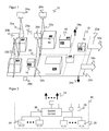
- FIG. 1 showed a schematic three-dimensional plan view of a detection system 10 on a conveyor belt 12 to be detected objects 14, on which codes 16 are mounted.
- the conveyor belt 12 is divided in two in a longitudinal direction corresponding to the arrows 18a-b indicating the direction of conveyance, so that there are two conveyor lines 20a-b with a parting line 22 therebetween.
- the conveyor belt 12 may be a conveyor belt in the strict sense, but also another system with objects 14 moving relative to the detection system 10.
- the detection system 10 each comprises two geometry detection sensors 24a-b to determine the object geometry of the objects 14, two code readers 26a-b for reading code information of the codes 16 and two encoders 28a-b for determining the feed of the two conveyor lines 20a-b of the conveyor belt 12th
- the detection area 30a-b of a single geometry detection sensor 24a-b is preferably as large as the width of a conveyor line 20a-b or slightly larger so that the two geometry detection sensors 24a-b determine geometry data of objects 14 across the full width of the conveyor belt 12. However, this does not necessarily have to be so long as essential parts of the conveyor belt 12, for example a large part of a seam are detected.
- the detection areas are also corresponding 32a-b of the code reader 26a-b designed.
- the detection system 10 thus has geometry data and code information of all objects 14 and codes 16 independent of the position on the conveyor belt 12.
- Corresponding object information is output in a manner explained below at output points 34a-b in the conveying direction below the detection system 10, for example to a higher-level control to initiate further processing steps on the objects 14, such as sorting based on the object information.
- other sensors can be mounted from a different perspective to capture geometries or codes from the side or bottom.
- FIG. 2 shows the detection system 10 again in a simplified block diagram.
- the geometry detection sensors 24, code reader 26 and encoder 28 are connected to a control and evaluation unit 36 of the detection system 10. There, the various acquired information is collected and processed and output corresponding object information via an output 38 at the output points 34 to the higher-level control.
- the control and evaluation unit 36 converts the sensor data into a common coordinate system.
- a common three-dimensional contour of the objects 14 on the conveyor belt 12 from which individual objects are identified and their geometric properties are determined like position, dimensions, volume.
- the three-dimensional contour can then be further simplified, for example by three-dimensional application of a tolerance field or enveloping of the objects 14 with simple bodies such as cuboids (bounding box).
- Suitable geometry detection sensors for example distance-measuring laser scanners, light-section sensors or 3D cameras, are known as such and are therefore not explained in detail. Incidentally, at least in some embodiments, they may additionally or even instead determine remission properties despite their main task of detecting geometric properties.
- code information of the codes 16 are read out everywhere on the conveyor belt.
- a code position is also determined.
- the procedure here depends on the type of code reader 26a-b.
- the code positions are determined from the direction of the reading beam by means of an integrated distance determination of the code readers 26a-b or by cutting with the three-dimensional contour of the geometry detection sensors 24a-b.
- the image is evaluated in order to locate the code 16, if necessary with reference to the three-dimensional contour.
- An RFID reader can locate the code 16, which in this case is a transponder, based on signal strengths or phases.
- the control and evaluation unit 36 thus knows both the position of the objects 14 and of the codes 16, the codes 16 can each be assigned to an object 14, whereby the read-out code information is made object information. It should be noted that the capturing and outputting of object information occurs at different positions on the conveyor belt 12. For this reason, the objects 14 are tracked (tracked) on the conveyor belt 12, the encoders 28a-b providing the necessary information about the movement or the feed of the conveyor belt 12.
- the control and evaluation unit 36 is able to track the objects 14 on the plurality of conveyor lines 20a-b according to their different conveying speed separately.
- the individual events such as the time of the geometry detection or the time of code reading, are then separately applied to the corresponding encoder line 20a-b encoder signal to correctly summarize the sensor data object information and to know when the object 14 on its respective conveyor line 20a-b an issue point 34a-b passes.
- the control and evaluation unit 36 divides the object stream into a plurality of sub-streams, each sub-stream being assigned a specific object class.
- a conceivable criterion for the definition of an object class is affiliation to a conveyor line 20a-b, ie ultimately the lateral position on the conveyor belt 12. To clearly decide on this even in borderline cases, for example, the position of the center of gravity of an object 14 or the largest area fraction be used on a conveyor line 20a-b. Even manual assignment or post-processing in critical cases is conceivable.
- object class can be derived from geometry properties such as length, width, height or volume of an object, remission properties, ie brightness or color, or the weight detected with an additional sensor. Then, for example, a partial flow with small objects and another partial flow with bright objects arise.
- the code information can also contribute and open up almost any feature space.
- a typical example is the sorting by destination addresses, so for example by postal code areas. It is possible, but by no means mandatory, that the number of object classes corresponds to the number of conveyor lines 20a-b.
- a separate output point 34a-b can now be configured. For example, thereby higher, larger or heavier objects 14 are discharged at a different position along the conveyor belt 12 as flat, small or light objects 14.
- the objects on different conveyor lines 20a-b are treated differently by their own output points 34a-b. It is not excluded that multiple output points 34a-b are configured to the same position.
- the different object classes are known at the moment when the object information is transferred to the higher-level controller. Therefore, it is still possible to treat the partial flows individually in order to discharge objects 14 conveyed on a left conveyor line 20a, for example, in a different direction than objects 14 conveyed on a right conveyor line 20b.
- the Figures 1 and 2 show an example with a two-part configuration in every respect.
- the invention is not limited thereto.
- objects 14 on conveyor belts 12 with additional conveyor lines 20 with a plurality of conveyor speeds can be processed by further sensors 24, 26, 28.
- the conveyor belt 12 is a uniform conveyor belt 12 of greater width.
- an encoder 28 is sufficient for detecting the conveying movement.
- the multiple conveyor lines 20a-b are then virtually virtual, and the dividing line 22 is no longer physically predetermined, but freely configurable. It is also possible in this case to completely dispense with a dividing line 22, thus not making the lateral position of an object 14 a criterion for the assignment to an object class.
- there are still several conveyor lines 20a-b which are not spatially separated, but practically folded in themselves and are defined by other object properties than the lateral position.
- the numbers of geometry sensors 24, code readers 26, conveyor lines 20 and output points 34 do not have to correspond to each other.
- the detection area 30 of a single geometry detection sensor 24 may be sufficient to cover the entire width of the conveyor belt 12, while narrower detection areas 32a-b of several code readers 26 have to be added or vice versa.
- the number of output points 34 does not necessarily depend on the number of conveyor lines 20a-b, because there may be virtual conveyor lines 20a-b, and because in addition to the lateral position of objects 14, other object properties may also be considered in the formation of object classes.
- the code readers 26 are understood in this context as detection sensors for a particular type of object information, namely the code content. Depending on which object properties are of interest, therefore, in some embodiments it is also possible to dispense with the code readers 26 or conversely the geometry detection sensors 28. In another variant, the geometry detection and the code reading is combined in each case a sensor, such as a distance-measuring code scanner or a 3D camera-based code reader.
- the dividing line 22 is not necessarily located between two physically separate conveyor lines 20a-b of different conveying speed. This opens up the possibility of adding, removing or dynamically changing virtual parting lines 22 in order to process different object streams, for example during a batch change.
- the configuration can be changed dynamically during operation. Such switching may affect the location of dividing lines 22 as well as other object properties that form the definition for object classes.
- the switching time is tracked with the aid of the encoder information up to the output points 34, so that at the moment of switching between detection and output objects 14 are handled properly.
- conveyor lines 20a-b formed by virtual parting lines 22 continue to apply until the changeover time has reached the associated output point 34a-b.
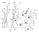
- FIG. 3 illustrates another form of dynamic adaptation of virtual dividing lines 22.
- a large object 14a is conveyed on a conveyor line 20a, which overhangs in the region of the other conveyor line 20b, so that its code 16a on the adjacent conveyor line 20b is read.
- the control and evaluation unit 36 compensates for this by temporarily displacing the parting line 22 and forming a bulge 40 in order to associate the entire large object 14a with a conveying line 20a.
Landscapes
- Physics & Mathematics (AREA)
- Engineering & Computer Science (AREA)
- Electromagnetism (AREA)
- Theoretical Computer Science (AREA)
- General Physics & Mathematics (AREA)
- General Health & Medical Sciences (AREA)
- Artificial Intelligence (AREA)
- Computer Vision & Pattern Recognition (AREA)
- Toxicology (AREA)
- Health & Medical Sciences (AREA)
- Data Mining & Analysis (AREA)
- Databases & Information Systems (AREA)
- General Engineering & Computer Science (AREA)
- Control Of Conveyors (AREA)
- Length Measuring Devices By Optical Means (AREA)
Abstract
Description
Die Erfindung betrifft ein Erfassungssystem zur Montage an einem Förderband und ein Verfahren zur Erfassung von Objekteigenschaften nach dem Oberbegriff von Anspruch 1 beziehungsweise 15.The invention relates to a detection system for mounting on a conveyor belt and a method for detecting object properties according to the preamble of claim 1 and 15, respectively.
Zur Automatisierung von Vorgängen an einem Förderband werden Sensoren eingesetzt, um Objekteigenschaften der geförderten Objekte zu erfassen und in Abhängigkeit davon weitere Bearbeitungsschritte einzuleiten. Solche Bearbeitungsschritte bestehen beispielsweise in der an das konkrete Objekt angepassten Weiterverarbeitung an einer Maschine, die auf geförderte Objekte einwirkt, oder in einer Veränderung des Objektstroms, indem bestimmte Objekte im Rahmen einer Qualitätskontrolle aus dem Objektstrom ausgeschleust werden oder der Objektstrom in mehrere Teilobjektströme sortiert wird.To automate processes on a conveyor belt, sensors are used to detect object properties of the conveyed objects and to initiate further processing steps depending thereon. Such processing steps consist, for example, in further processing adapted to the specific object on a machine which acts on conveyed objects, or in a change of the object stream in that certain objects are removed from the object stream as part of a quality control or the object stream is sorted into a plurality of partial object streams.
Das Anbringen eines Barcodes oder eines zweidimensionalen Codes kann als eine derartige Objekteigenschaft aufgefasst werden, die dem Objekt eigens aufgeprägt wird, um den Objekten individuelle Unterscheidungsmerkmale zu geben und dadurch derartige Aufgaben zu erleichtern. Bei solchen Code tragenden Objekten können deshalb Objekteigenschaften sowohl durch allgemeine Sensoren etwa durch die Bestimmung von geometrischen Objekteigenschaften als auch durch Codeleser erfasst werden, welche die Codes auslesen.The affixing of a bar code or a two-dimensional code can be understood as such an object characteristic that is specially impressed on the object in order to give the objects individual distinguishing features and thereby facilitate such tasks. In the case of objects carrying such code, therefore, object properties can be detected both by general sensors, for example by the determination of geometric object properties, as well as by code readers which read the codes.
Die verbreitetsten Codeleser sind Barcodescanner, welche einen Barcode oder Strichcode mit einem Laserlesestrahl quer zum Code abtasten. Sie werden an Supermarktkassen, zur automatischen Paketidentifikation, Sortierung von Postsendungen oder bei der Gepäckabfertigung in Flughäfen und in anderen Logistikanwendungen häufig eingesetzt. Mit der Weiterentwicklung der digitalen Kameratechnologie werden Barcodescanner zunehmend durch kamerabasierte Codeleser abgelöst. Statt Codebereiche abzuscannen, nimmt ein kamerabasierter Codeleser mit Hilfe eines CCD-Chips Bilder der Objekte mit den darauf befindlichen Codes auf, und eine Bildauswertungssoftware extrahiert aus diesen Bildern die Codeinformation. Kamerabasierte Codeleser kommen problemlos auch mit anderen Codearten als eindimensionalen Strichcodes zurecht, die wie ein Matrixcode auch zweidimensional aufgebaut sind und mehr Informationen zur Verfügung stellen. In einer wichtigen Anwendungsgruppe werden die Code tragenden Objekte an dem Codeleser vorbei gefördert. Eine Kamera, häufig eine Kamerazeile, liest die Objektbilder mit den Codeinformationen sukzessive mit der Relativbewegung ein.The most common code readers are bar code scanners which scan a bar code or bar code with a laser read beam across the code. They are often used in supermarket cash registers, automatic parcel identification, mail sorting or baggage handling in airports and other logistics applications. As digital camera technology evolves, barcode scanners become more popular increasingly replaced by camera-based code readers. Instead of scanning code areas, a camera-based code reader uses a CCD chip to capture images of the objects with the codes thereon, and image analysis software extracts the code information from these images. Camera-based code readers can easily cope with code types other than one-dimensional barcodes, which, like a matrix code, are also two-dimensional and provide more information. In an important application group, the code-carrying objects are conveyed past the code reader. A camera, often a camera line, reads the object images with the code information successively with the relative movement.
Eine Art von Codeleser, der auf einer gänzlich anderen Technologie basiert, ist ein RFID-Leser (Radio Frequency Identification). Dabei ist an dem zu identifizierenden Objekt anstelle eines optischen Codes ein Transponder angebracht. Der Zweck bleibt derselbe, nämlich eine Wiedererkennung von Objekten für eine individualisierte Behandlung zu ermöglichen.One type of code reader based on a completely different technology is a Radio Frequency Identification (RFID) reader. In this case, instead of an optical code, a transponder is attached to the object to be identified. The purpose remains the same, namely to allow recognition of objects for individualized treatment.
Der Erfassungsbereich eines einzelnen Sensors reicht oft nicht aus, um sämtliche relevanten Informationen über die Objekte auf einem Förderband aufzunehmen. Gerade beim Codelesen sind regelmäßig mehrere Sensoren vorgesehen, um Objekte von mehreren oder allen Seiten aufzunehmen, damit die Codes auf beliebigen Seiten der Objekte aufgebracht sein können. Die einzelnen Sensoren werden zu einem Erfassungssystem zusammengefasst, in dem meist eine gemeinsame Steuerung die verschiedenen Sensordaten aufbereitet, ehe sie an eine übergeordnete Steuerung der Anlage übergeben werden, zu welcher das Förderband gehört.The detection range of a single sensor is often insufficient to capture all relevant information about the objects on a conveyor. Especially when reading code several sensors are regularly provided to accommodate objects from several or all sides, so that the codes can be applied to any side of the objects. The individual sensors are combined to form a detection system in which usually a common control prepares the various sensor data before they are transferred to a higher-level control of the system to which the conveyor belt belongs.
Es ist weiterhin bekannt, Codelesern einen zusätzlichen Geometriesensor vorzuordnen, etwa einen entfernungsmessenden Laserscanner. Man erhält auf diese Weise vorab Informationen, welche Objekte sich auf dem Förderband befinden und welche Geometrie diese Objekte aufweisen. Andererseits wird die Position eines Codes während des Lesens bestimmt. Damit ist es eindeutig möglich, den Code und damit dessen Codeinformationen einem Objekt zuzuordnen.It is also known to pre-assign code readers an additional geometry sensor, such as a distance-measuring laser scanner. In this way, it is possible to obtain in advance information as to which objects are located on the conveyor belt and which geometry these objects have. On the other hand, the position of a code during reading is determined. Thus, it is clearly possible to assign the code and thus its code information to an object.
Die Position eines Codes lässt sich in einem Barcodescanner durch eine integrierte Abstandsbestimmung messen. Es stehen dann nämlich über den Scanwinkel, den Winkel der Scanebene und den Abstand dreidimensionale Polarkoordinaten der Codeposition zur Verfügung. Alternativ wird kein Abstand gemessen, sondern der Schnittpunkt des Lesestrahls mit der bekannten Objektgeometrie ermittelt. Ein kamerabasierter Codeleser erkennt die Codeposition durch Bildverarbeitung und eventuelle Korrekturen durch Verrechnung mit der Objektgeometrie. Für RFID-Leser sind Lokalisierungen anhand der Signalstärke des RFID-Signals oder anhand von Phasenmessungen bekannt, wobei allerdings derzeit im Stand der Technik noch nicht alle Schwierigkeiten beherrscht werden, um stets eine zuverlässige und eindeutige Transponderposition zu erhalten.The position of a code can be measured in a bar code scanner by an integrated distance determination. Namely, it is then about the scan angle, the angle of the scan plane and the distance three-dimensional polar coordinates of the code position to disposal. Alternatively, no distance is measured, but the point of intersection of the reading beam with the known object geometry is determined. A camera-based code reader recognizes the code position by image processing and possible corrections by offsetting with the object geometry. For RFID readers, localizations are known based on the signal strength of the RFID signal or on phase measurements, although not all difficulties are currently mastered in the prior art in order to always obtain a reliable and unambiguous transponder position.
Objekteigenschaften und Codeinformationen werden bei Verwendung eines zusätzlichen Geometriesensors in unterschiedlichen Förderpositionen ermittelt, und die Ausgabe der verarbeiteten Objekteigenschaften für die Steuerung des weiteren Objektflusses, wie Codeinformationen, Gewicht oder Geometrie des Objekts, erfolgt an einem nochmals in Förderrichtung versetzten Ausgabepunkt. Um während der Förderbewegung die Zuordnung zu einem Objekt zu erhalten, wird das Objekt auf Basis der gemessenen oder bekannten Fördergeschwindigkeit oder eines Wegsignals eines an dem Förderband angebrachten Encoders verfolgt.Object properties and code information are determined when using an additional geometry sensor in different conveyor positions, and the output of the processed object properties for controlling the further object flow, such as code information, weight or geometry of the object, takes place at an output point offset again in the conveying direction. In order to obtain the assignment to an object during the conveying movement, the object is tracked on the basis of the measured or known conveying speed or a path signal of an encoder mounted on the conveyor belt.
Diese Objektverfolgung (Tracking) mündet allerdings herkömmlich in nur einem einzigen Ausgabepunkt. Die übergeordnete Steuerung erhält also die Objektinformationen immer, wenn sich ein Objekt an ein und derselben Position des Förderbandes befindet. Damit ist es nicht möglich, in dieser Hinsicht zwischen den Objekten zu differenzieren.However, this object tracking leads conventionally in only a single output point. The higher-level control thus always receives the object information when an object is at one and the same position of the conveyor belt. Thus, it is not possible to differentiate between the objects in this regard.
In besonderem Maße stellt sich dieses Problem, wenn mehrere Förderbänder direkt nebeneinander angeordnet sind. Dies ist für die Erhöhung des Objektdurchsatzes von Vorteil. Ein ähnlicher Effekt wird erreicht, indem das Förderband mit beispielsweise doppelter Breite ausgeführt und mehrere Objekte nebeneinander gefördert werden. Das entspricht praktisch mehreren Förderlinien mit untereinander gleicher Geschwindigkeit.This problem particularly arises when several conveyor belts are arranged directly next to each other. This is advantageous for increasing the object throughput. A similar effect is achieved by making the conveyor with double width, for example, and conveying several objects side by side. This practically corresponds to several conveyor lines with mutually equal speed.
Ein herkömmliches Erfassungssystem kann mit dieser Situation nicht umgehen, weil der einzige Ausgabepunkt nur auf die Bedürfnisse eines Förderbandes zugeschnitten werden kann und deshalb für die weiteren Förderbänder allenfalls zufällig oder durch Anpassungen der gesamten Anlage geeignet ist. Die übergeordnete Steuerung hat auch gar keine Kenntnis, auf welchem der mehreren Förderbänder sich das aktuell den Ausgabepunkt passierende Objekt befindet. Deshalb ist nach heutigem Stand der Technik erforderlich, auf jedem der Förderbänder getrennt arbeitende Erfassungssysteme zu montieren. Informationen aus Überlappungen eines Erfassungsbereichs mit einem benachbarten Förderband bleiben nicht nur ungenutzt, sie müssen sogar durch entsprechende mechanische Anordnung oder Software-Algorithmen ausgeblendet werden. Dadurch ist der Kostenaufwand erheblich erhöht.A conventional detection system can not handle this situation, because the only output point can only be tailored to the needs of a conveyor belt and therefore suitable for the other conveyor belts at best by chance or by adjustments to the entire system. The higher-level controller also has no knowledge on which of the several conveyor belts the object currently passing the output point is located. Therefore, according to the current state of Technique required to mount separately on each of the conveyor belts working detection systems. Information from overlaps of a detection area with an adjacent conveyor belt not only remain unused, they must even be hidden by appropriate mechanical arrangement or software algorithms. As a result, the cost is significantly increased.
Die
Es ist daher Aufgabe der Erfindung, ein Erfassungssystem zu schaffen, welches Objekte auf einem Förderband flexibler verarbeiten kann.It is therefore an object of the invention to provide a detection system which can process objects on a conveyor belt more flexible.
Diese Aufgabe wird durch ein Erfassungssystem zur Montage an einem Förderband und ein Verfahren zur Erfassung von Objekteigenschaften nach Anspruch 1 beziehungsweise 15 gelöst. Dabei geht die Erfindung von dem Grundgedanken aus, den gesamten Objektstrom auf dem Förderband als Zusammensetzung von mehreren Teilströmen jeweils einer Objektklasse aufzufassen, die sich durch bestimmte Objekteigenschaften definieren. Die Objektklassen können dann auf unterschiedliche Weise behandelt werden. An dem Förderband ist für jede Objektklasse ein Ausgabepunkt festlegbar oder konfigurierbar. Bevorzugt werden demnach die Objektinformationen gerade zu dem Zeitpunkt beispielsweise an eine übergeordnete Steuerung ausgegeben, in dem das betreffende Objekt den Ausgabepunkt erreicht. Alternativ werden die Objektinformationen asynchron übertragen und enthalten eine Zeitinformation, wann sich das Objekt am Ausgabepunkt befindet. Damit wird dann aber das abgestimmte Zeitverhalten in dem Erfassungssystem erschwert, und unerwartete Schwankungen der Förderbewegung können dazu führen, dass die Zeitinformation nicht mehr stimmt.This object is achieved by a detection system for mounting on a conveyor belt and a method for detecting object properties according to claim 1 or 15. The invention is based on the basic idea of conceiving the entire object stream on the conveyor belt as the composition of a plurality of partial streams of an object class in each case, which are defined by specific object properties. The object classes can then be handled in different ways. An output point can be defined or configured on the conveyor belt for each object class. Accordingly, the object information is preferably output at the time, for example, to a higher-level control, in which the object in question reaches the output point. Alternatively, the object information is transmitted asynchronously and contains time information as to when the object is at the output point. This, however, complicates the coordinated time behavior in the detection system, and unexpected fluctuations in the conveying movement can lead to the time information no longer being correct.
Vorzugsweise werden die Ausgabepunkte für jede Objektklasse unterschiedlich gesetzt, um unterschiedliche Bearbeitungsschritte an den Objekten vorzunehmen. In manchen Anwendungen ist aber auch vorstellbar, die Ausgabepunkte mehrerer oder aller Objektklassen zusammenfallen zu lassen. Aufgrund der übertragenen Objektinformationen kennt die übergeordnete Steuerung auch dann noch die zugehörige Objektklasse.Preferably, the output points are set differently for each object class to perform different processing steps on the objects. In some applications, however, it is also conceivable to let the output points of several or all object classes coincide. Due to the transmitted object information, the higher-level controller still knows the associated object class.
Die Objektinformationen können jede Art von erfassten Objekteigenschaften oder daraus abgeleitete Informationen umfassen, oder im Minimalfall lediglich in einem binären Signal bestehen, welches durch seine Übergabe am Ausgabepunkt implizit mitteilt, dass aktuell ein Objekt einer bestimmten Objektklasse den Ausgabepunkt passiert. Die übergeordnete Steuerung entscheidet, ob eine Handlung eingeleitet wird, etwa das Ausschleusen des betreffenden Objekts, und inwieweit die Objektinformationen diese Entscheidung beeinflussen.The object information can comprise any type of detected object properties or information derived therefrom, or in the minimum case only consist of a binary signal which by its transfer at the output point implicitly informs that an object of a certain object class is currently passing the output point. The higher-level controller decides whether an action is initiated, such as the removal of the relevant object, and to what extent the object information influences this decision.
Die Erfindung hat den Vorteil, dass das Erfassungssystem zusätzliche Verarbeitungsmöglichkeiten bietet. Objekte müssen nicht mehr einheitlich am gleichen Ausgabepunkt weiterverarbeitet werden. Dadurch erweitert sich das Anwendungsspektrum beziehungsweise es können Anwendungen mit weniger Sensorik gelöst werden.The invention has the advantage that the detection system provides additional processing capabilities. Objects no longer need to be processed consistently at the same output point. As a result, the range of applications expands or applications with less sensor technology can be solved.
Mindestens ein Erfassungssensor ist bevorzugt als Codeleser ausgebildet, insbesondere als kamerabasierter Codeleser, Barcodescanner oder RFID-Leser. Die gelesenen Codeinformationen können Teil der Objekteigenschaften sein, die in die Einteilung in eine Objektklasse einfließen, und auch Teil der ausgegebenen Objektinformationen. Ein kamerabasierter Codeleser weist einen zeilen- oder matrixförmigen Bildsensor auf, mit dem ein Bild während der Relativbewegung des Objekts auf dem Förderband zusammengesetzt oder in einer Art Schnappschuss aufgenommen wird.At least one detection sensor is preferably designed as a code reader, in particular as a camera-based code reader, bar code scanner or RFID reader. The read code information may be part of the object properties that are included in the classification into an object class and also part of the output object information. A camera-based code reader has a line or matrix-shaped image sensor, with which an image is assembled during the relative movement of the object on the conveyor belt or recorded in a kind of snapshot.
Die Position eines gelesenen Codes ist bevorzugt in dem Codeleser bestimmbar, wobei die Auswertungseinheit dafür ausgebildet ist, den Code anhand seiner Position einem Objekt zuzuordnen. Durch die Zuordnung wird die Codeinformation zu einer Objekteigenschaft. Die ermittelte Codeposition wird nach der Erfassung auf dem Förderband gemäß dessen Vorschub weiterverfolgt ("getrackt"). In einem kamerabasierten Codeleser erfolgt die Positionsbestimmung vorzugsweise durch Bildverarbeitung. Ein Barcodescanner nutzt wie einleitend beschrieben eine integrierte Abstandsbestimmung oder bestimmt den Auftreffpunkt des Lesestrahls anhand von bekannten Geometrieeigenschaften des codetragenden Objekts. Für RFID-Leser sind Lokalisierungsverfahren für den Transponder anhand von Signalstärken oder Phasen der RFID-Signale bekannt, die fortlaufend verbessert werden.The position of a code read is preferably determinable in the code reader, wherein the evaluation unit is adapted to the code based on its position to assign to an object. The mapping turns the code information into an object property. The determined code position is traced after the detection on the conveyor belt according to its feed ("tracked"). In a camera-based code reader, the position determination is preferably carried out by image processing. As described in the introduction, a barcode scanner uses an integrated distance determination or determines the point of impact of the reading beam on the basis of known geometry properties of the code-carrying object. For RFID readers localization methods for the transponder based on signal strengths or phases of the RFID signals are known, which are continuously improved.
Mindestens ein Erfassungssensor ist bevorzugt als Geometrieerfassungssensor ausgebildet. Damit werden Objekte auf dem Förderband samt ihren Abmessungen erkannt. Wenn das Erfassungssystem sowohl Codeleser als auch Geometrieerfassungssensoren umfasst, gibt es verschiedene Konfigurationen. Der Geometrieerfassungssensor kann separat ausgebildet sein und ist dem Codeleser dann vorzugsweise vorgeordnet, so dass die Geometriedaten vom Codeleser bereits nutzbar sind, etwa für eine Fokussierung. Es ist aber auch möglich, Geometrieerfassung und Codelesen in einem Sensor zusammenzufassen. Dazu kann bei Barcodescannern eine integrierte Abstandsmessung durch Lichtlaufzeitmessung dienen. Kamerabasierte Codeleser können als 3D-Kameras ausgebildet sein und Geometrien über ein Stereoskopieverfahren, ein Lichtlaufzeitverfahren oder ein Lichtschnittverfahren etwa anhand von Verformungen einer Beleuchtungslinie durch die Objektkonturen messen.At least one detection sensor is preferably designed as a geometry detection sensor. This detects objects on the conveyor belt and their dimensions. If the detection system includes both code readers and geometry detection sensors, there are various configurations. The geometry detection sensor can be designed separately and is then preferably arranged upstream of the code reader so that the geometry data can already be used by the code reader, for example for focusing. But it is also possible to combine geometry acquisition and code reading in one sensor. For barcode scanners, an integrated distance measurement can be used by measuring the time of flight. Camera-based code readers can be designed as 3D cameras and measure geometries via a stereoscopic method, a light transit time method or a light-section method, for example based on deformations of a lighting line through the object contours.
Vorzugsweise weist das Erfassungssystem mindestens einen Geschwindigkeitssensor zur Bestimmung der Fördergeschwindigkeit des Förderbandes oder mindestens einen Wegsensor zur Bestimmung des Vorschubs des Förderbandes auf. Der Ausgabepunkt liegt an einer festlegbaren Position auf dem Förderband hinter dem Ort der Erfassung. Über den von einem Geschwindigkeits- oder Wegsensor gemessenen Vorschub kann erkannt werden, zu welchem Zeitpunkt ein Objekt bis zu dem Ausgabepunkt gefördert wurde. Alternativ zu einer Messung des Vorschubs kann ein Bewegungsprofil des Förderbandes vorgegeben oder von einer übergeordneten Steuerung mitgeteilt werden. Sofern das Förderband wie weiter unten beschrieben mehrere Förderlinien mit unterschiedlicher Fördergeschwindigkeit umfasst, ist auch das Anbringen mehrerer Geschwindigkeits- oder Wegsensoren denkbar.Preferably, the detection system has at least one speed sensor for determining the conveying speed of the conveyor belt or at least one displacement sensor for determining the feed of the conveyor belt. The dispensing point is located at a definable position on the conveyor behind the location of detection. By means of the feed measured by a speed or displacement sensor, it can be recognized at which time an object was conveyed to the output point. As an alternative to a measurement of the feed, a movement profile of the conveyor belt can be specified or communicated by a higher-level controller. If the conveyor belt, as described below, comprises a plurality of conveyor lines with a different conveyor speed, it is also conceivable to attach a plurality of speed or distance sensors.
Die Objekteigenschaften umfassen bevorzugt mindestens eine der folgenden Eigenschaften: eine Breite, eine Höhe, eine Länge, ein Volumen, einen Flächeninhalt einer Auflagefläche des Objekts oder eines das Objekt umhüllenden Körpers, eine Remissionseigenschaft oder ein Gewicht. Damit sind die am häufigsten benötigten Objektgeometrieeigenschaften umfasst. Die Auflagefläche bezieht sich nicht notwendig auf die Fläche mit tatsächlichem Kontakt zwischen Förderband und Objekt. Eine senkrechte Projektion der Objektkontur auf das Förderband beschreibt in manchen Situationen den beanspruchten Platz noch besser. Remissionseigenschaften können abstrakt als Quantifizierung einer starken oder schwachen Remission oder konkreter als Grauwerte oder Farben erfasst werden. Mit Gewicht und Volumen sind zwei besonders wichtige Eigenschaften für die Abrechnung und Transportplanung in der Logistik erfasst.The object properties preferably include at least one of the following properties: a width, a height, a length, a volume, an area of a bearing surface of the object or a body enveloping the object, a remission property or a weight. This includes the most commonly used object geometry properties. The bearing surface does not necessarily refer to the surface with actual contact between conveyor belt and object. A vertical projection of the object contour on the conveyor belt describes in some situations the claimed space even better. Remission properties can be captured abstractly as a quantification of a strong or weak remission, or more specifically as gray values or colors. With weight and volume, two particularly important characteristics for billing and transport planning in logistics are covered.
Das Erfassungssystem weist bevorzugt mehrere Erfassungssensoren auf, deren Erfassungsbereiche sich in Breitenrichtung des Förderbandes ergänzen. Damit werden auch Förderbänder mit großer Breite abgedeckt, die das maximale Gesichtsfeld eines einzelnen Erfassungssensors überschreiten. Diese Kombination mehrerer Erfassungssensoren ist sowohl für Geometrieerfassungssensoren wie für Codeleser möglich. Die Auswertungseinheit ist bevorzugt dafür ausgebildet, die Objekteigenschaften der Erfassungssensoren zu fusionieren. Dabei werden beispielsweise Bilddaten zusammengesetzt (stitching) oder die erfassten Objekteigenschaften und Codeinformationen so zusammengefasst, als wären sie von einem einzelnen Erfassungssensor bestimmt, welcher die volle Breite des Förderbandes erfasst.The detection system preferably has a plurality of detection sensors whose detection ranges are complementary in the width direction of the conveyor belt. This also covers wide-width conveyors that exceed the maximum field of view of a single acquisition sensor. This combination of multiple acquisition sensors is possible for both geometry acquisition sensors and code readers. The evaluation unit is preferably designed to fuse the object properties of the detection sensors. For example, image data is stitched together or the captured object properties and code information summarized as if they were determined by a single detection sensor, which detects the full width of the conveyor belt.
Die Auswertungseinheit ist bevorzugt dafür ausgebildet, von mehreren Erfassungssensoren erfasste Objekteigenschaften in ein gemeinsames Koordinatensystem umzurechnen. Dies ist ein wichtiges Beispiel für Datenfusion von mehreren Erfassungssensoren. Voraussetzung für eine Umrechnung in ein gemeinsames Koordinatensystem ist die Kenntnis der gegenseitigen Position und Ausrichtung der Erfassungssensoren, die in einer als Registrierung bezeichneten Kalibrierung bestimmt werden kann.The evaluation unit is preferably designed to convert object properties detected by a plurality of detection sensors into a common coordinate system. This is an important example of data fusion of multiple acquisition sensors. The prerequisite for a conversion into a common coordinate system is the knowledge of the mutual position and orientation of the detection sensors, which can be determined in a calibration called registration.
Die Auswertungseinheit ist bevorzugt dafür ausgebildet, Objekte anhand ihrer Position auf dem Förderband in Querrichtung in mindestens zwei Objektklassen zu unterteilen, insbesondere anhand mindestens einer Trennlinie längs des Förderbandes. Das Förderband wird somit in mehrere Förderlinien unterteilt (Multi Line). Die Trennlinie zwischen den Förderlinien muss nicht unbedingt in Längsrichtung gerade durchgezogen sein, sondern kann beispielsweise eine Ausbuchtung aufweisen, um ein größeres Objekt einer Förderlinie zuzuordnen. Innerhalb einer Förderlinie sind zusätzliche Unterteilungen in weitere Objektklassen anhand anderer Objekteigenschaften möglich. Man kann auch in Ausführungsformen, bei denen die Objektposition in Querrichtung beziehungsweise die laterale Objektposition keine Objektklassen bildende Eigenschaft ist, die verschiedenen Objektklassen als verschiedene Förderlinien auffassen, die sich dann sozusagen räumlich überlagern und durch andere Objekteigenschaften differenzieren. Aufgrund der Unterscheidung anhand der Position auf dem Förderband in Querrichtung genügt ein einziges Erfassungssystem, so dass sich die Kosten reduzieren. Der Aufbau des Erfassungssystems ist unabhängig von der Anzahl von Förderlinien, solange die Erfassungssensoren gemeinsam die Förderbandbreite abdecken können. Dabei ist eine direkte Zuordnung von jeweils einem Erfassungssensor zu einer Förderlinie möglich, aber keineswegs zwingend erforderlich.The evaluation unit is preferably designed to subdivide objects based on their position on the conveyor belt in the transverse direction in at least two classes of objects, in particular based on at least one dividing line along the conveyor belt. The conveyor belt is thus subdivided into several conveyor lines (Multi Line). The dividing line between the conveyor lines does not necessarily have to be straight in the longitudinal direction, but may, for example, have a bulge to a larger object attributable to a conveyor line. Within a conveyor line, additional subdivisions into further object classes are possible based on other object properties. In embodiments in which the object position in the transverse direction or the lateral object position is not a feature forming property classes, it is also possible to conceive the different object classes as different conveyor lines, which then superimpose, so to speak, spatially and differentiate by other object properties. Due to the distinction between the position on the conveyor belt in the transverse direction, a single detection system is sufficient so that the costs are reduced. The structure of the detection system is independent of the number of conveyor lines as long as the detection sensors can jointly cover the conveyor belt width. In this case, a direct assignment of a respective detection sensor to a conveyor line is possible, but by no means absolutely necessary.
Die Objekte werden in den verschiedenen Spuren oder Förderlinien verfolgt oder getrackt und an dem jeweils zu einer Objektklasse gehörigen Ausgabepunkt ausgegeben. Somit können beispielsweise Objekte jeder Förderlinie an einer anderen Position ausgeschleust werden. Die Ausgabepunkte von zwei Förderlinien können auch auf gleicher Höhe liegen. Denn die übergeordnete Steuerung hat dennoch am Ausgabepunkt aufgrund der Zugehörigkeit zu einer Objektklasse Kenntnis darüber, auf welcher Förderlinie sich ein aktuell passierendes Objekt befindet, und kann den Bearbeitungsschritt darauf ausrichten, beispielsweise indem Objekte auf einer rechten Förderlinie nach rechts und auf einer linken Förderlinie nach links ausgeschleust werden.The objects are tracked or tracked in the various tracks or conveyor lines and output at the respective output point belonging to an object class. Thus, for example, objects of each conveyor line can be discharged at a different position. The output points of two conveyor lines can also be at the same height. Because the higher-level control has nevertheless at the output point on the basis of belonging to an object class on which conveyor line a currently passing object is, and can align the processing step, for example, by objects on a right conveyor line to the right and on a left conveyor line to the left be discharged.
Die Auswertungseinheit ist bevorzugt dafür ausgebildet, eine Trennlinie dynamisch zu verschieben. Diese Verschiebung kann über die gesamte Länge der Trennlinie erfolgen, um das Förderband neu aufzuteilen. Denkbar ist aber auch eine Verschiebung nur in einem Teilbereich, beispielsweise um eine Ausbuchtung für ein größeres Objekt zu schaffen oder auszulösen. Die Verschiebung der Trennlinie ist automatisch und manuell möglich.The evaluation unit is preferably designed to dynamically shift a separation line. This shift can be made over the entire length of the dividing line to redistribute the conveyor belt. It is also conceivable, however, to shift only in one partial area, for example to create or trigger a bulge for a larger object. The shift of the dividing line is possible automatically and manually.
Die Trennlinie ist bevorzugt eine tatsächliche Trennlinie zwischen mehreren Förderlinien des Förderbands. In dieser Ausführungsform sollen mehrere benachbarte, aber physisch getrennte Förderbänder vom gleichen Erfassungssystem erfasst werden. Dabei sind unter Umständen auch unterschiedliche Geschwindigkeiten der einzelnen Förderbänder zu verarbeiten. Alternativ kann die Trennlinie auch eine virtuelle Trennlinie sein, die ein einziges Förderband aufteilt. Dabei kann es sich auch um eines der mehreren benachbarten Förderbänder handeln, wobei dann sowohl tatsächliche als auch virtuelle Trennlinien gezogen sind.The dividing line is preferably an actual dividing line between a plurality of conveying lines of the conveyor belt. In this embodiment, multiple adjacent but physically separate conveyor belts are to be detected by the same detection system. Under certain circumstances, different speeds of the individual conveyor belts can be processed. Alternatively, the dividing line may also be a virtual dividing line which divides a single conveyor belt. It can also be one of the act on several adjacent conveyor belts, in which case both actual and virtual dividing lines are drawn.
Die Ausbildungseinheit ist bevorzugt dafür ausgebildet, die Anzahl der berücksichtigten Trennlinien zu verändern. Dabei werden Trennlinien hinzugefügt oder entfernt, etwa weil eine neue Charge von Objekten zu bearbeiten ist. Beispielsweise können in einer Charge kleine Objekte zu dritt oder viert nebeneinander liegen, während in einer anschließenden Charge nur große Objekte vorhanden sind, welche die gesamte Breite beanspruchen und deshalb eine Trennlinie überflüssig machen. Virtuelle Trennlinien können frei gelöscht oder hinzugefügt werden. Tatsächliche Trennlinien zwischen voneinander separierten, benachbarten Förderbändern bleiben natürlich erhalten, aber das Erfassungssystem kann entscheiden, ob es diese physische Trennung als Trennlinie berücksichtigt beziehungsweise behandelt oder nicht.The training unit is preferably designed to change the number of dividing lines considered. Separators are added or removed, for example, because a new batch of objects has to be edited. For example, in a batch, small objects may lie side by side or four next to each other, while in a subsequent batch only large objects are present, which occupy the entire width and therefore make a dividing line superfluous. Virtual dividers can be freely deleted or added. Actual dividing lines between mutually separated, adjacent conveyor belts are of course preserved, but the detection system can decide whether or not to consider this physical separation as a dividing line.
Die Auswertungseinheit ist bevorzugt dafür ausgebildet, die Zuordnung anhand der Position in Querrichtung durch den Schwerpunkt des Objekts oder den größten Anteil der Auflagefläche des Objekts zu bestimmen. Im einfachsten Fall befindet sich die gesamte Objektkontur innerhalb ein und derselben Förderlinie. Ist dies aber nicht erfüllt, so muss ein Kriterium gefunden werden, zu welcher Förderlinie das Objekt gehören soll. Die Auflagefläche kann wie schon weiter oben auch durch eine senkrechte Projektion der dreidimensionalen Objektkontur auf das Förderband definiert sein. Der Schwerpunkt und die Auflagefläche können sowohl auf die Objektkontur als auch auf einen Hüllkörper, etwa ein umhüllendes Rechteck oder Quader (Bounding Box) bezogen sein. Schließlich kann die Zuordnung auch manuell erfolgen, sei es von vorne herein oder nur in Einzelfällen zu Kontrolle oder Nachbearbeitung in kritischen Fällen.The evaluation unit is preferably designed to determine the assignment based on the position in the transverse direction through the center of gravity of the object or the largest portion of the bearing surface of the object. In the simplest case, the entire object contour is located within one and the same conveyor line. But if this is not fulfilled, a criterion must be found to which conveyor line the object should belong. The support surface can be defined on the conveyor belt as above by a vertical projection of the three-dimensional object contour. The center of gravity and the bearing surface can be related both to the object contour and to an enveloping body, such as an enveloping rectangle or box (bounding box). Finally, the assignment can also be done manually, either from the outset or only in individual cases to control or post-processing in critical cases.
Die Auswertungseinheit ist bevorzugt dafür ausgebildet, während des Betriebs zu einem Umschaltzeitpunkt die Kriterien für die Unterteilung von Objekten in Objektklassen zu verändern, wobei an einem Ausgabepunkt so lange Objektinformationen nach den früheren Kriterien ausgegeben werden, bis ein zum Umschaltzeitpunkt erfasster Bereich des Förderbandes den Ausgabepunkt passiert hat. Die frühere Konfiguration bleibt dann aber vorübergehend für die bereits erfassten, jedoch noch nicht ausgegebenen Objektinformationen gültig. Es muss also quasi der Umschaltzeitpunkt vom Ort der Erfassung zu den Ausgabepunkten verfolgt beziehungsweise getrackt werden. Besonders anschaulich ist dies bei einer Verlagerung von Trennlinien: diese werden zunächst nur am Ort der Erfassung verschoben, und die neue Trennlinienkonfiguration verschiebt sich dann mit der Bewegung des Förderbandes bis zu den Ausgabepunkten.The evaluation unit is preferably designed to change the criteria for the subdivision of objects into object classes during operation at a switching time, whereby object information is output according to the earlier criteria at an output point until an area of the conveyor belt detected at the changeover time passes the output point Has. However, the previous configuration then remains temporarily valid for the object information already acquired but not yet output. So it is almost the switching time from the place of detection to the output points tracked or tracked. This is particularly evident in the case of a shift of dividing lines: these are initially moved only at the place of capture, and the new dividing line configuration then shifts with the movement of the conveyor belt to the output points.
Das erfindungsgemäße Verfahren kann auf ähnliche Weise weitergebildet werden und zeigt dabei ähnliche Vorteile. Derartige vorteilhafte Merkmale sind beispielhaft, aber nicht abschließend in den sich an die unabhängigen Ansprüche anschließenden Unteransprüchen beschrieben.The method according to the invention can be developed in a similar manner and shows similar advantages. Such advantageous features are described by way of example but not exhaustively in the subclaims following the independent claims.
Die Erfindung wird nachstehend auch hinsichtlich weiterer Merkmale und Vorteile beispielhaft anhand von Ausführungsformen und unter Bezug auf die beigefügte Zeichnung näher erläutert. Die Abbildungen der Zeichnung zeigen in:
- Fig. 1
- eine schematische dreidimensionale Draufsicht auf ein Erfassungssystem an einem Förderband mit zu erfassenden Objekten;
- Fig. 2
- ein vereinfachtes Blockschaltbild eines Erfassungssystems; und
- Fig. 3
- eine Darstellung ähnlich
Figur 1 mit einem Förderband, auf dem ein größeres Objekt mehr als eine Förderlinie beansprucht.
- Fig. 1
- a schematic three-dimensional plan view of a detection system on a conveyor belt with objects to be detected;
- Fig. 2
- a simplified block diagram of a detection system; and
- Fig. 3
- a representation similar
FIG. 1 with a conveyor belt on which a larger object claims more than one conveyor line.
Der Erfassungsbereich 30a-b eines einzelnen Geometrieerfassungssensors 24a-b ist vorzugsweise so groß wie die Breite einer Förderlinie 20a-b oder etwas größer, so dass die beiden Geometrieerfassungssensoren 24a-b Geometriedaten von Objekten 14 über die volle Breite des Förderbandes 12 bestimmen. Das muss aber nicht zwingend so sei, solange wesentliche Teile des Förderbandes 12, beispielsweise ein Großteil einer Nahtstelle erfasst wird. Entsprechend sind auch die Erfassungsbereiche 32a-b der Codeleser 26a-b ausgelegt. Dem Erfassungssystem 10 stehen also Geometriedaten und Codeinformationen aller Objekte 14 und Codes 16 unabhängig von der Position auf dem Förderband 12 zur Verfügung. Entsprechende Objektinformationen werden in einer weiter unten erläuterten Weise an Ausgabepunkten 34a-b in Förderrichtung unterhalb des Erfassungssystems 10 beispielsweise an eine übergeordnete Steuerung ausgegeben, um weitere Bearbeitungsschritte an den Objekten 14 einzuleiten, etwa eine Sortierung anhand der Objektinformationen. Wie einleitend beschrieben, können weitere, nicht dargestellte Sensoren aus anderer Perspektive angebracht werden, um Geometrien oder Codes von der Seite oder von unten zu erfassen.The
Die Steuer- und Auswertungseinheit 36 rechnet die Sensordaten in ein gemeinsames Koordinatensystem um. Es entsteht somit durch Addition der Erfassungsbereiche 30a-b der Geometrieerfassungssensoren 24a-b in der Breite und sukzessiv im Laufe der Förderbewegung in der Länge eine gemeinsame dreidimensionale Kontur der Objekte 14 auf dem Förderband 12, woraus einzelne Objekte identifiziert und deren geometrische Eigenschaften bestimmt werden, wie Position, Abmessungen, Volumen. Die dreidimensionale Kontur kann anschließend noch vereinfacht werden, etwa durch dreidimensionales Beaufschlagen mit einem Toleranzfeld beziehungsweise Umhüllen der Objekte 14 mit einfachen Körpern wie Quadern (Bounding Box). Geeignete Geometrieerfassungssensoren, beispielsweise entfernungsmessende Laserscanner, Lichtschnittsensoren oder 3D-Kameras, sind als solche bekannt und werden deshalb nicht näher erläutert. Sie können im Übrigen zumindest in manchen Ausführungsformen trotz ihrer Hauptaufgabe, geometrische Eigenschaften zu erfassen, zusätzlich oder sogar stattdessen Remissionseigenschaften bestimmen.The control and
Durch eine entsprechende Addition der Erfassungsbereiche 32a-b der Codeleser 26a-b werden überall auf dem Förderband Codeinformationen der Codes 16 ausgelesen. Dabei wird zugleich auch eine Codeposition bestimmt. Das Vorgehen hängt hier vom Typ des Codelesers 26a-b ab. Bei einem Codescanner werden aus der Richtung des Lesestrahls mit Hilfe einer integrierten Abstandsbestimmung der Codeleser 26a-b oder durch Schneiden mit der dreidimensionalen Kontur der Geometrieerfassungssensoren 24a-b die Codepositionen ermittelt. Bei einem kamerabasierten Codeleser 26a-b wird das Bild ausgewertet, um den Code 16 zu lokalisieren, gegebenenfalls unter Verrechnung mit der dreidimensionalen Kontur. Ein RFID-Leser kann den in diesem Falle als Transponder ausgebildeten Code 16 aufgrund von Signalstärken oder Phasen lokalisieren.By a corresponding addition of the
Da der Steuer- und Auswertungseinheit 36 somit sowohl die Position der Objekte 14 als auch der Codes 16 bekannt ist, können die Codes 16 jeweils einem Objekt 14 zugeordnet werden, wodurch die ausgelesenen Codeinformationen zu Objektinformationen gemacht werden. Dabei ist zu beachten, dass die Erfassungen und die Ausgabe von Objektinformationen an unterschiedlichen Positionen an dem Förderband 12 erfolgt. Aus diesem Grund werden die Objekte 14 auf dem Förderband 12 verfolgt (getrackt), wobei die Encoder 28a-b die hierfür notwendigen Informationen über die Bewegung beziehungsweise den Vorschub des Förderbandes 12 liefern.Since the control and
Die Steuer- und Auswertungseinheit 36 ist dabei in der Lage, die Objekte 14 auf den mehreren Förderlinien 20a-b entsprechend deren unterschiedlicher Fördergeschwindigkeit getrennt zu verfolgen. Die einzelnen Ereignisse wie Zeitpunkt der Geometrieerfassung oder Zeitpunkt der Codelesung werden dann separat mit dem für die jeweilige Förderlinie 20a-b passenden Encodersignal beaufschlagt, um die Sensordaten korrekt zu Objektinformationen zusammenzufassen und um zu wissen, wann das Objekt 14 auf seiner jeweiligen Förderlinie 20a-b einen Ausgabepunkt 34a-b passiert.The control and
Aufgrund der erfassten Objekteigenschaften unterteilt die Steuer- und Auswertungseinheit 36 den Objektstrom in mehrere Teilströme, wobei jedem Teilstrom eine bestimmte Objektklasse zugeordnet ist. Ein denkbares Kriterium für die Definition einer Objektklasse ist die Zugehörigkeit zu einer Förderlinie 20a-b, also letztlich die laterale Position auf dem Förderband 12. Um darüber auch in Grenzfällen eindeutig zu entscheiden, kann beispielsweise die Lage des Schwerpunkts eines Objekts 14 oder der größte Flächenanteil auf einer Förderlinie 20a-b herangezogen werden. Auch manuelle Zuordnung oder Nachbearbeitung in kritischen Fällen ist denkbar.On the basis of the detected object properties, the control and
Andere Kriterien für Definition einer Objektklasse können aus Geometrieeigenschaften, wie Länge, Breite, Höhe oder Volumen eines Objekts, aus Remissionseigenschaften, also Helligkeit oder Farbe, oder dem mit einem zusätzlichen Sensor erfassten Gewicht abgeleitet werden. Dann entstehen beispielsweise ein Teilstrom mit kleinen Objekten und ein anderer Teilstrom mit hellen Objekten. Auch die Codeinformationen können beitragen und eröffnen einen nahezu beliebigen Merkmalsraum. Ein typisches Beispiel ist aber die Sortierung nach Zieladressen, also beispielsweise nach Postleitzahlenbereichen. Es ist möglich, aber keineswegs zwingend, dass die Anzahl der Objektklassen der Anzahl der Förderlinien 20a-b entspricht.Other criteria for defining an object class can be derived from geometry properties such as length, width, height or volume of an object, remission properties, ie brightness or color, or the weight detected with an additional sensor. Then, for example, a partial flow with small objects and another partial flow with bright objects arise. The code information can also contribute and open up almost any feature space. A typical example, however, is the sorting by destination addresses, so for example by postal code areas. It is possible, but by no means mandatory, that the number of object classes corresponds to the number of
Für jeden Teilstrom und damit jede den Teilstrom definierende Objektklasse kann nun ein eigener Ausgabepunkt 34a-b konfiguriert werden. Beispielweise werden dadurch höhere, größere oder schwerere Objekte 14 an einer anderen Position längs des Förderbandes 12 ausgeschleust als flache, kleine oder leichte Objekte 14. Insbesondere werden die Objekte auf unterschiedlichen Förderlinien 20a-b durch eigene Ausgabepunkte 34a-b unterschiedlich behandelt. Dabei wird nicht ausgeschlossen, dass mehrere Ausgabepunkte 34a-b auf dieselbe Position konfiguriert werden. Trotz dieser Übereinstimmung sind nämlich die unterschiedlichen Objektklassen im Moment der Übergabe der Objektinformationen an die übergeordnete Steuerung bekannt. Es besteht deshalb weiterhin die Möglichkeit, die Teilströme individuell zu behandeln, um etwa auf einer linken Förderlinie 20a geförderte Objekte 14 in eine andere Richtung auszuschleusen als auf einer rechten Förderlinie 20b geförderte Objekte 14.For each sub-stream and thus each object class defining the sub-stream, a
Die
Die Anzahlen von Geometriesensoren 24, Codelesern 26, Förderlinien 20 und Ausgabepunkten 34 müssen einander nicht entsprechen. Beispielsweise kann der Erfassungsbereich 30 eines einzigen Geometrieerfassungssensors 24 ausreichen, die gesamte Breite des Förderbandes 12 abzudecken, während sich dafür schmalere Erfassungsbereiche 32a-b mehrerer Codeleser 26 addieren müssen oder umgekehrt. Dabei ist nicht erforderlich, dass ein Erfassungsbereich 32a-b gerade einer Förderlinie 20a-b entspricht, obwohl dies die Konfiguration, Wartung und Übersicht erleichtert, da die erfassten Objektinformationen ohnehin in der Steuer- und Auswertungseinheit 36 fusioniert werden und deshalb unabhängig von der tatsächlichen Anzahl von Erfassungssensoren 24, 26 sind. Die Anzahl der Ausgabepunkte 34 richtet sich nicht deshalb zwingend nach der Anzahl von Förderlinien 20a-b, weil es virtuelle Förderlinien 20a-b geben kann und weil zusätzlich zu der lateralen Position von Objekten 14 auch andere Objekteigenschaften bei der Bildung von Objektklassen berücksichtigt werden können.The numbers of
Die Codeleser 26 werden in diesem Zusammenhang als Erfassungssensoren für eine besondere Art von Objektinformationen aufgefasst, nämlich dem Codeinhalt. Je nachdem, für welche Objekteigenschaften man sich interessiert, kann deshalb in manchen Ausführungsformen auch auf die Codeleser 26 oder umgekehrt auf die Geometrieerfassungssensoren 28 verzichtet werden. In einer anderen Variante ist die Geometrieerfassung und die Codelesung in jeweils einem Sensor zusammengefasst, wie bei einem entfernungsmessenden Codescanner oder einem 3D-kamerabasierten Codeleser.The
Wie schon erläutert, liegt die Trennlinie 22 nicht zwingend zwischen zwei physisch getrennten Förderlinien 20a-b unterschiedlicher Fördergeschwindigkeit. Dies eröffnet die Möglichkeit, virtuelle Trennlinien 22 hinzuzufügen, zu entfernen oder dynamisch zu verändern, um unterschiedliche Objektströme beispielsweise bei einem Chargenwechsel zu bearbeiten. Dabei kann die Umschaltung der Konfiguration dynamisch im laufenden Betrieb erfolgen. Eine solche Umschaltung kann die Lage von Trennlinien 22 ebenso betreffen wie andere Objekteigenschaften, welche die Definition für Objektklassen bilden. Bei einer Umschaltung im laufenden Betrieb wird der Umschaltzeitpunkt mit Hilfe der Encoderinformationen bis zu den Ausgabepunkten 34 verfolgt, damit im Moment der Umschaltung zwischen Erfassung und Ausgabe befindliche Objekte 14 richtig behandelt werden. Insbesondere gelten durch virtuelle Trennlinien 22 gebildete Förderlinien 20a-b noch so lange weiter, bis der Umschaltzeitpunkt den zugehörigen Ausgabepunkt 34a-b erreicht hat.As already explained, the dividing
Claims (15)
dadurch gekennzeichnet,
dass die Auswertungseinheit (36) dafür ausgebildet ist, die Objekte (14) anhand der Objekteigenschaften in mindestens zwei Objektklassen zu unterteilen, und dass ein Ausgabepunkt (34) an dem Förderband (12) für jede Objektklasse festlegbar ist.Detection system (10) for mounting on a conveyor belt (12) with at least one detection sensor (24, 26) for detecting object properties of conveyed on the conveyor belt (12) objects (14) and with an evaluation unit (36) for output from the object properties derived object information at a definable output point (34) of the conveyor belt (12),
characterized,
in that the evaluation unit (36) is designed to subdivide the objects (14) into at least two object classes on the basis of the object properties, and that an output point (34) can be fixed to the conveyor belt (12) for each object class.
wobei mindestens ein Erfassungssensor (26) als Codeleser ausgebildet ist, insbesondere als kamerabasierter Codeleser, Barcodescanner oder RFID-Leser.A detection system (10) according to claim 1,
wherein at least one detection sensor (26) is designed as a code reader, in particular as a camera-based code reader, bar code scanner or RFID reader.
wobei die Position eines gelesenen Codes (16) in dem Codeleser (26) bestimmbar ist, und wobei die Auswertungseinheit (36) dafür ausgebildet ist, den Code (16) anhand seiner Position einem Objekt (14) zuzuordnen.A detection system (10) according to claim 2,
wherein the position of a read code (16) in the code reader (26) can be determined, and wherein the evaluation unit (36) is adapted to assign the code (16) based on its position an object (14).
wobei mindestens ein Erfassungssensor (24) als Geometrieerfassungssensor ausgebildet ist.Detection system (10) according to one of the preceding claims,
wherein at least one detection sensor (24) is designed as a geometry detection sensor.
das mindestens einen Geschwindigkeitssensor (28) zur Bestimmung der Fördergeschwindigkeit des Förderbandes (12) oder mindestens einen Wegsensor (28) zur Bestimmung des Vorschubs des Förderbandes (12) aufweist.Detection system (10) according to one of the preceding claims,
the at least one speed sensor (28) for determining the conveying speed of the conveyor belt (12) or at least one displacement sensor (28) for determining the feed of the conveyor belt (12).
wobei die Objekteigenschaften mindestens eine der folgenden Eigenschaften umfassen: eine Breite, eine Höhe, eine Länge, ein Volumen, einen Flächeninhalt einer Auflagefläche des Objekts (14) oder eines das Objekt (14) umhüllenden Körpers, eine Remissionseigenschaft oder ein Gewicht.Detection system (10) according to one of the preceding claims,
wherein the object properties include at least one of the following properties: a width, a height, a length, a volume, a surface area of a bearing surface of the object (14), or an object enveloping the object (14) Body, a remission characteristic or a weight.
wobei die Auswertungseinheit (36) dafür ausgebildet ist, von mehreren Erfassungssensoren (24a-b, 26a-b) erfasste Objekteigenschaften in ein gemeinsames Koordinatensystem umzurechnen.Detection system (10) according to claim 7,
wherein the evaluation unit (36) is designed to convert object properties detected by a plurality of detection sensors (24a-b, 26a-b) into a common coordinate system.
wobei die Auswertungseinheit (36) dafür ausgebildet ist, eine Trennlinie (22) dynamisch zu verschieben.Detection system (10) according to claim 9,
wherein the evaluation unit (36) is adapted to dynamically shift a parting line (22).
wobei die Trennlinie (22) eine tatsächliche Trennlinie zwischen mehreren Förderlinien (20a-b) des Förderbands (12) ist.Detection system (10) according to claim 9,
wherein the parting line (22) is an actual parting line between a plurality of conveyor lines (20a-b) of the conveyor belt (12).
wobei die Auswertungseinheit (36) dafür ausgebildet ist, die Anzahl der berücksichtigten Trennlinien (22) zu verändern.A detection system (10) according to any one of claims 9 to 11,
wherein the evaluation unit (36) is adapted to change the number of considered dividing lines (22).
wobei die Auswertungseinheit (36) dafür ausgebildet ist, die Zuordnung anhand der Position in Querrichtung durch den Schwerpunkt des Objekts (14) oder den größten Anteil der Auflagefläche des Objekts (14) zu bestimmen.A detection system (10) according to any one of claims 9 to 12,
wherein the evaluation unit (36) is adapted to determine the assignment based on the position in the transverse direction by the center of gravity of the object (14) or the largest portion of the support surface of the object (14).
wobei die Auswertungseinheit (36) dafür ausgebildet ist, während des Betriebs zu einem Umschaltzeitpunkt die Kriterien für die Unterteilung von Objekten (14) in Objektklassen zu verändern, wobei an einem Ausgabepunkt (34) so lange Objektinformationen nach den früheren Kriterien ausgegeben werden, bis ein zum Umschaltzeitpunkt erfasster Bereich des Förderbandes (12) den Ausgabepunkt (34) passiert hat.Detection system (10) according to one of the preceding claims,
wherein the evaluation unit (36) is adapted to change during operation at a switching time the criteria for the subdivision of objects (14) into object classes, wherein at an output point (34) as long as object information is output according to the earlier criteria, to a area of the conveyor belt (12) detected at the changeover time has passed the discharge point (34).
dadurch gekennzeichnet,
dass die Objekte (14) anhand der Objekteigenschaften in mindestens zwei Objektklassen unterteilt werden, und dass jeweils ein Ausgabepunkt (34) an dem Förderband (12) für jede Objektklasse festgelegt wird.Method for detecting object properties of objects (14) conveyed on a conveyor belt (12) with at least one detection sensor (24, 26) in which object information derived from the object properties is output at a definable output point (34) of the conveyor belt (12),
characterized,
in that the objects (14) are subdivided into at least two object classes on the basis of the object properties, and in each case an output point (34) is defined on the conveyor belt (12) for each object class.
Priority Applications (5)
| Application Number | Priority Date | Filing Date | Title |
|---|---|---|---|
| DK12178680.0T DK2693362T3 (en) | 2012-07-31 | 2012-07-31 | Detection system for mounting on a conveyor belt |
| EP12178680.0A EP2693362B1 (en) | 2012-07-31 | 2012-07-31 | Detection system for mounting on a conveyor belt |
| ES12178680.0T ES2545374T3 (en) | 2012-07-31 | 2012-07-31 | Detection system for mounting on a conveyor belt |
| US13/934,894 US9193534B2 (en) | 2012-07-31 | 2013-07-03 | Detection system for installation at a conveyor belt |
| CN201310292477.7A CN103575245B (en) | 2012-07-31 | 2013-07-12 | For installing detecting system on a moving belt |
Applications Claiming Priority (1)
| Application Number | Priority Date | Filing Date | Title |
|---|---|---|---|
| EP12178680.0A EP2693362B1 (en) | 2012-07-31 | 2012-07-31 | Detection system for mounting on a conveyor belt |
Publications (2)
| Publication Number | Publication Date |
|---|---|
| EP2693362A1 true EP2693362A1 (en) | 2014-02-05 |
| EP2693362B1 EP2693362B1 (en) | 2015-06-17 |
Family
ID=47018023
Family Applications (1)
| Application Number | Title | Priority Date | Filing Date |
|---|---|---|---|
| EP12178680.0A Active EP2693362B1 (en) | 2012-07-31 | 2012-07-31 | Detection system for mounting on a conveyor belt |
Country Status (5)
| Country | Link |
|---|---|
| US (1) | US9193534B2 (en) |
| EP (1) | EP2693362B1 (en) |
| CN (1) | CN103575245B (en) |
| DK (1) | DK2693362T3 (en) |
| ES (1) | ES2545374T3 (en) |
Cited By (60)
| Publication number | Priority date | Publication date | Assignee | Title |
|---|---|---|---|---|
| DE202014101714U1 (en) | 2014-04-10 | 2015-07-14 | Sick Ag | Code reading system for reading codes |
| CN106482775A (en) * | 2016-11-28 | 2017-03-08 | 无锡特恒科技有限公司 | Dual sensor detection components |
| WO2017056035A1 (en) * | 2015-09-30 | 2017-04-06 | Datalogic Ip Tech S.R.L. | System and method for reading coded information |
| WO2017184310A1 (en) * | 2016-04-18 | 2017-10-26 | Symbol Technologies, Llc | Barcode scanning and dimensioning |
| EP3290770A1 (en) * | 2016-09-01 | 2018-03-07 | Sick AG | Monitoring device |
| US10140725B2 (en) | 2014-12-05 | 2018-11-27 | Symbol Technologies, Llc | Apparatus for and method of estimating dimensions of an object associated with a code in automatic response to reading the code |
| US10145955B2 (en) | 2016-02-04 | 2018-12-04 | Symbol Technologies, Llc | Methods and systems for processing point-cloud data with a line scanner |
| CN109230342A (en) * | 2018-10-15 | 2019-01-18 | 中国铁道科学研究院集团有限公司电子计算技术研究所 | Safety check transmission equipment |
| CN109879025A (en) * | 2019-03-05 | 2019-06-14 | 威海新北洋技术服务有限公司 | Object separation method and device side by side |
| US10352689B2 (en) | 2016-01-28 | 2019-07-16 | Symbol Technologies, Llc | Methods and systems for high precision locationing with depth values |
| US10354411B2 (en) | 2016-12-20 | 2019-07-16 | Symbol Technologies, Llc | Methods, systems and apparatus for segmenting objects |
| US10451405B2 (en) | 2016-11-22 | 2019-10-22 | Symbol Technologies, Llc | Dimensioning system for, and method of, dimensioning freight in motion along an unconstrained path in a venue |
| US10521914B2 (en) | 2017-09-07 | 2019-12-31 | Symbol Technologies, Llc | Multi-sensor object recognition system and method |
| EP3591567A1 (en) * | 2018-07-02 | 2020-01-08 | Sick AG | Optoelectronic sensor and method for repeated optical detection of objects at different object distances |
| US10572763B2 (en) | 2017-09-07 | 2020-02-25 | Symbol Technologies, Llc | Method and apparatus for support surface edge detection |
| US10591918B2 (en) | 2017-05-01 | 2020-03-17 | Symbol Technologies, Llc | Fixed segmented lattice planning for a mobile automation apparatus |
| US10663590B2 (en) | 2017-05-01 | 2020-05-26 | Symbol Technologies, Llc | Device and method for merging lidar data |
| US10721451B2 (en) | 2016-03-23 | 2020-07-21 | Symbol Technologies, Llc | Arrangement for, and method of, loading freight into a shipping container |
| US10726273B2 (en) | 2017-05-01 | 2020-07-28 | Symbol Technologies, Llc | Method and apparatus for shelf feature and object placement detection from shelf images |
| US10731970B2 (en) | 2018-12-13 | 2020-08-04 | Zebra Technologies Corporation | Method, system and apparatus for support structure detection |
| US10740911B2 (en) | 2018-04-05 | 2020-08-11 | Symbol Technologies, Llc | Method, system and apparatus for correcting translucency artifacts in data representing a support structure |
| US10776661B2 (en) | 2016-08-19 | 2020-09-15 | Symbol Technologies, Llc | Methods, systems and apparatus for segmenting and dimensioning objects |
| US10809078B2 (en) | 2018-04-05 | 2020-10-20 | Symbol Technologies, Llc | Method, system and apparatus for dynamic path generation |
| US10823572B2 (en) | 2018-04-05 | 2020-11-03 | Symbol Technologies, Llc | Method, system and apparatus for generating navigational data |
| US10832436B2 (en) | 2018-04-05 | 2020-11-10 | Symbol Technologies, Llc | Method, system and apparatus for recovering label positions |
| US10949798B2 (en) | 2017-05-01 | 2021-03-16 | Symbol Technologies, Llc | Multimodal localization and mapping for a mobile automation apparatus |
| EP3813355A1 (en) * | 2019-10-25 | 2021-04-28 | Sick Ag | Camera for detecting an object stream and method for determining the height of objects |
| US11003188B2 (en) | 2018-11-13 | 2021-05-11 | Zebra Technologies Corporation | Method, system and apparatus for obstacle handling in navigational path generation |
| US11010920B2 (en) | 2018-10-05 | 2021-05-18 | Zebra Technologies Corporation | Method, system and apparatus for object detection in point clouds |
| US11015938B2 (en) | 2018-12-12 | 2021-05-25 | Zebra Technologies Corporation | Method, system and apparatus for navigational assistance |
| US11042161B2 (en) | 2016-11-16 | 2021-06-22 | Symbol Technologies, Llc | Navigation control method and apparatus in a mobile automation system |
| US11079240B2 (en) | 2018-12-07 | 2021-08-03 | Zebra Technologies Corporation | Method, system and apparatus for adaptive particle filter localization |
| US11080566B2 (en) | 2019-06-03 | 2021-08-03 | Zebra Technologies Corporation | Method, system and apparatus for gap detection in support structures with peg regions |
| US11093896B2 (en) | 2017-05-01 | 2021-08-17 | Symbol Technologies, Llc | Product status detection system |
| US11090811B2 (en) | 2018-11-13 | 2021-08-17 | Zebra Technologies Corporation | Method and apparatus for labeling of support structures |
| US11100303B2 (en) | 2018-12-10 | 2021-08-24 | Zebra Technologies Corporation | Method, system and apparatus for auxiliary label detection and association |
| CN113315786A (en) * | 2021-06-25 | 2021-08-27 | 郑州信源信息技术股份有限公司 | Security authentication method and system |
| US11107238B2 (en) | 2019-12-13 | 2021-08-31 | Zebra Technologies Corporation | Method, system and apparatus for detecting item facings |
| US11151743B2 (en) | 2019-06-03 | 2021-10-19 | Zebra Technologies Corporation | Method, system and apparatus for end of aisle detection |
| US11200677B2 (en) | 2019-06-03 | 2021-12-14 | Zebra Technologies Corporation | Method, system and apparatus for shelf edge detection |
| US11327504B2 (en) | 2018-04-05 | 2022-05-10 | Symbol Technologies, Llc | Method, system and apparatus for mobile automation apparatus localization |
| US11341663B2 (en) | 2019-06-03 | 2022-05-24 | Zebra Technologies Corporation | Method, system and apparatus for detecting support structure obstructions |
| US11367092B2 (en) | 2017-05-01 | 2022-06-21 | Symbol Technologies, Llc | Method and apparatus for extracting and processing price text from an image set |
| US11378161B2 (en) | 2016-12-23 | 2022-07-05 | Igus Gmbh | Monitoring system for operating an energy chain |
| US11392891B2 (en) | 2020-11-03 | 2022-07-19 | Zebra Technologies Corporation | Item placement detection and optimization in material handling systems |
| US11402846B2 (en) | 2019-06-03 | 2022-08-02 | Zebra Technologies Corporation | Method, system and apparatus for mitigating data capture light leakage |
| US11416000B2 (en) | 2018-12-07 | 2022-08-16 | Zebra Technologies Corporation | Method and apparatus for navigational ray tracing |
| US11450024B2 (en) | 2020-07-17 | 2022-09-20 | Zebra Technologies Corporation | Mixed depth object detection |
| US11449059B2 (en) | 2017-05-01 | 2022-09-20 | Symbol Technologies, Llc | Obstacle detection for a mobile automation apparatus |
| US11506483B2 (en) | 2018-10-05 | 2022-11-22 | Zebra Technologies Corporation | Method, system and apparatus for support structure depth determination |
| US11507103B2 (en) | 2019-12-04 | 2022-11-22 | Zebra Technologies Corporation | Method, system and apparatus for localization-based historical obstacle handling |
| US11593915B2 (en) | 2020-10-21 | 2023-02-28 | Zebra Technologies Corporation | Parallax-tolerant panoramic image generation |
| US11592826B2 (en) | 2018-12-28 | 2023-02-28 | Zebra Technologies Corporation | Method, system and apparatus for dynamic loop closure in mapping trajectories |
| US11600084B2 (en) | 2017-05-05 | 2023-03-07 | Symbol Technologies, Llc | Method and apparatus for detecting and interpreting price label text |
| US11662739B2 (en) | 2019-06-03 | 2023-05-30 | Zebra Technologies Corporation | Method, system and apparatus for adaptive ceiling-based localization |
| US11822333B2 (en) | 2020-03-30 | 2023-11-21 | Zebra Technologies Corporation | Method, system and apparatus for data capture illumination control |
| DE102022118414A1 (en) | 2022-07-22 | 2024-01-25 | Karlsruher Institut für Technologie, Körperschaft des öffentlichen Rechts | Sorting system for sorting objects in a material stream according to object classes and method for sorting objects conveyed in a material stream according to object classes |
| US11954882B2 (en) | 2021-06-17 | 2024-04-09 | Zebra Technologies Corporation | Feature-based georegistration for mobile computing devices |
| US11960286B2 (en) | 2019-06-03 | 2024-04-16 | Zebra Technologies Corporation | Method, system and apparatus for dynamic task sequencing |
| US11978011B2 (en) | 2017-05-01 | 2024-05-07 | Symbol Technologies, Llc | Method and apparatus for object status detection |
Families Citing this family (19)
| Publication number | Priority date | Publication date | Assignee | Title |
|---|---|---|---|---|
| DE102013106926A1 (en) * | 2013-07-02 | 2015-01-08 | Khs Gmbh | Method for detecting the degree of filling of a transport route |
| US9195669B2 (en) * | 2014-02-26 | 2015-11-24 | Iboss, Inc. | Detecting and managing abnormal data behavior |
| US10301122B2 (en) * | 2014-10-29 | 2019-05-28 | Fives Intralogistics S.P.A. Con Socio Unico | Device for feeding items to a sorting machine and sorting machine |
| CN104826805B (en) * | 2015-05-14 | 2017-08-25 | 合肥海明科技股份有限公司 | A kind of Express Logistics Automated Sorting System and its method for sorting based on RFID |
| CN105425308A (en) * | 2015-12-18 | 2016-03-23 | 同方威视技术股份有限公司 | System and method for article tracking |
| DE102016113006A1 (en) * | 2016-07-14 | 2018-01-18 | Krones Ag | Container treatment plant with redundant safety systems |
| CN107661862B (en) * | 2016-07-27 | 2020-11-03 | 边隆祥 | Express delivery automatic sorting array type camera system |
| DE102016114182B4 (en) * | 2016-08-01 | 2023-06-15 | Tdk-Micronas Gmbh | Conveying device and method for conveying an object |
| CN106391492B (en) * | 2016-08-30 | 2019-01-15 | 丁煦 | Object automatic sorting device and its control method |
| LU100782B1 (en) * | 2018-04-27 | 2019-10-28 | Soremartec Sa | System for conveying products in succession along an industrial line |
| US10689200B1 (en) * | 2018-09-28 | 2020-06-23 | Amazon Technologies, Inc. | Sorting system that transfers payloads from a conveyor system onto mobile drive units without the conveyor system knowing destinations of the mobile drive units |
| US10745213B2 (en) | 2018-09-28 | 2020-08-18 | Amazon Technologies, Inc. | Conveyor system having sensors to time transfer of payloads onto moving mobile drive units |
| DK3708265T3 (en) * | 2019-03-11 | 2021-07-12 | Sick Ag | SORT DETECTION SYSTEM FOR DETECTING AN OBJECT THAT PASSES THROUGH ONE OF A MULTIPLE OF OPENINGS |
| CN110404785B (en) * | 2019-08-02 | 2021-07-16 | 盐城正邦环保科技有限公司 | Automatic sorting line wrapping and loading system and method based on three-dimensional vision |
| CN112766007A (en) * | 2019-11-06 | 2021-05-07 | 联策科技股份有限公司 | Intelligent code reading positioning system and method |
| DE102020112430B4 (en) * | 2020-05-07 | 2021-12-23 | Sick Ag | Camera and method for detecting objects |
| US11847832B2 (en) | 2020-11-11 | 2023-12-19 | Zebra Technologies Corporation | Object classification for autonomous navigation systems |
| US11667474B1 (en) * | 2021-08-27 | 2023-06-06 | Amazon Technologies, Inc. | Increasing scan rate of parcels within material handling facility |
| US11724895B1 (en) * | 2021-09-23 | 2023-08-15 | Amazon Technologies, Inc. | Directed palletization using lights |
Citations (2)
| Publication number | Priority date | Publication date | Assignee | Title |
|---|---|---|---|---|
| EP1363228B1 (en) | 1996-12-30 | 2006-03-08 | Datalogic S.P.A. | Method and machine for reading and associating optical codes |
| EP2048596A1 (en) * | 2007-10-10 | 2009-04-15 | Sick Ag | Device and method for recording images of objects moved on a supply device |
Family Cites Families (10)
| Publication number | Priority date | Publication date | Assignee | Title |
|---|---|---|---|---|
| EP1000701B1 (en) * | 1998-11-10 | 2006-10-11 | Fuji Photo Film Co., Ltd. | Orientation recognition and sorting apparatus for recyclable cameras |
| US6471044B1 (en) * | 1999-04-30 | 2002-10-29 | Siemens Electrocom, L.P. | Hold and release singulator |
| WO2000066280A2 (en) * | 1999-04-30 | 2000-11-09 | Siemens Electrocom, L.P. | Item singulation system |
| DE19940403A1 (en) * | 1999-08-25 | 2001-03-01 | Sick Ag | Method and device for identifying and determining the position of objects |
| WO2006027802A1 (en) * | 2004-09-07 | 2006-03-16 | Petromodel Ehf | Apparatus and method for analysis of size, form and angularity and for compositional analysis of mineral and rock particles |
| ATE370387T1 (en) * | 2004-10-11 | 2007-09-15 | Sick Ag | DEVICE AND METHOD FOR MONITORING MOVING OBJECTS |
| JP2008172062A (en) * | 2007-01-12 | 2008-07-24 | Murata Mach Ltd | Article feeding apparatus |
| DE502007002821D1 (en) * | 2007-08-10 | 2010-03-25 | Sick Ag | Recording of equalized images of moving objects with uniform resolution by line sensor |
| US8201681B2 (en) * | 2008-07-14 | 2012-06-19 | Siemens Industry, Inc. | Method for gapping for sortation rate maximization |
| CN201926431U (en) * | 2010-12-27 | 2011-08-10 | 昱鑫科技(苏州)有限公司 | Expansion classifier |
-
2012
- 2012-07-31 EP EP12178680.0A patent/EP2693362B1/en active Active
- 2012-07-31 DK DK12178680.0T patent/DK2693362T3/en active
- 2012-07-31 ES ES12178680.0T patent/ES2545374T3/en active Active
-
2013
- 2013-07-03 US US13/934,894 patent/US9193534B2/en active Active
- 2013-07-12 CN CN201310292477.7A patent/CN103575245B/en active Active
Patent Citations (2)
| Publication number | Priority date | Publication date | Assignee | Title |
|---|---|---|---|---|
| EP1363228B1 (en) | 1996-12-30 | 2006-03-08 | Datalogic S.P.A. | Method and machine for reading and associating optical codes |
| EP2048596A1 (en) * | 2007-10-10 | 2009-04-15 | Sick Ag | Device and method for recording images of objects moved on a supply device |
Cited By (69)
| Publication number | Priority date | Publication date | Assignee | Title |
|---|---|---|---|---|
| DE202014101714U1 (en) | 2014-04-10 | 2015-07-14 | Sick Ag | Code reading system for reading codes |
| US10140725B2 (en) | 2014-12-05 | 2018-11-27 | Symbol Technologies, Llc | Apparatus for and method of estimating dimensions of an object associated with a code in automatic response to reading the code |
| WO2017056035A1 (en) * | 2015-09-30 | 2017-04-06 | Datalogic Ip Tech S.R.L. | System and method for reading coded information |
| EP3356994B1 (en) | 2015-09-30 | 2019-11-06 | Datalogic IP TECH S.r.l. | System and method for reading coded information |
| US10352689B2 (en) | 2016-01-28 | 2019-07-16 | Symbol Technologies, Llc | Methods and systems for high precision locationing with depth values |
| US10145955B2 (en) | 2016-02-04 | 2018-12-04 | Symbol Technologies, Llc | Methods and systems for processing point-cloud data with a line scanner |
| US10721451B2 (en) | 2016-03-23 | 2020-07-21 | Symbol Technologies, Llc | Arrangement for, and method of, loading freight into a shipping container |
| GB2564360A (en) * | 2016-04-18 | 2019-01-09 | Symbol Technologies Llc | Barcode scanning and dimensioning |
| GB2564360B (en) * | 2016-04-18 | 2021-09-29 | Symbol Technologies Llc | Barcode scanning and dimensioning |
| US9805240B1 (en) | 2016-04-18 | 2017-10-31 | Symbol Technologies, Llc | Barcode scanning and dimensioning |
| WO2017184310A1 (en) * | 2016-04-18 | 2017-10-26 | Symbol Technologies, Llc | Barcode scanning and dimensioning |
| US10776661B2 (en) | 2016-08-19 | 2020-09-15 | Symbol Technologies, Llc | Methods, systems and apparatus for segmenting and dimensioning objects |
| EP3290770A1 (en) * | 2016-09-01 | 2018-03-07 | Sick AG | Monitoring device |
| US11042161B2 (en) | 2016-11-16 | 2021-06-22 | Symbol Technologies, Llc | Navigation control method and apparatus in a mobile automation system |
| US10451405B2 (en) | 2016-11-22 | 2019-10-22 | Symbol Technologies, Llc | Dimensioning system for, and method of, dimensioning freight in motion along an unconstrained path in a venue |
| CN106482775B (en) * | 2016-11-28 | 2019-01-01 | 无锡特恒科技有限公司 | Dual sensor detection components |
| CN106482775A (en) * | 2016-11-28 | 2017-03-08 | 无锡特恒科技有限公司 | Dual sensor detection components |
| US10354411B2 (en) | 2016-12-20 | 2019-07-16 | Symbol Technologies, Llc | Methods, systems and apparatus for segmenting objects |
| US11378161B2 (en) | 2016-12-23 | 2022-07-05 | Igus Gmbh | Monitoring system for operating an energy chain |
| US11449059B2 (en) | 2017-05-01 | 2022-09-20 | Symbol Technologies, Llc | Obstacle detection for a mobile automation apparatus |
| US10663590B2 (en) | 2017-05-01 | 2020-05-26 | Symbol Technologies, Llc | Device and method for merging lidar data |
| US10949798B2 (en) | 2017-05-01 | 2021-03-16 | Symbol Technologies, Llc | Multimodal localization and mapping for a mobile automation apparatus |
| US10726273B2 (en) | 2017-05-01 | 2020-07-28 | Symbol Technologies, Llc | Method and apparatus for shelf feature and object placement detection from shelf images |
| US10591918B2 (en) | 2017-05-01 | 2020-03-17 | Symbol Technologies, Llc | Fixed segmented lattice planning for a mobile automation apparatus |
| US11093896B2 (en) | 2017-05-01 | 2021-08-17 | Symbol Technologies, Llc | Product status detection system |
| US11978011B2 (en) | 2017-05-01 | 2024-05-07 | Symbol Technologies, Llc | Method and apparatus for object status detection |
| US11367092B2 (en) | 2017-05-01 | 2022-06-21 | Symbol Technologies, Llc | Method and apparatus for extracting and processing price text from an image set |
| US11600084B2 (en) | 2017-05-05 | 2023-03-07 | Symbol Technologies, Llc | Method and apparatus for detecting and interpreting price label text |
| US10521914B2 (en) | 2017-09-07 | 2019-12-31 | Symbol Technologies, Llc | Multi-sensor object recognition system and method |
| US10572763B2 (en) | 2017-09-07 | 2020-02-25 | Symbol Technologies, Llc | Method and apparatus for support surface edge detection |
| US10832436B2 (en) | 2018-04-05 | 2020-11-10 | Symbol Technologies, Llc | Method, system and apparatus for recovering label positions |
| US10823572B2 (en) | 2018-04-05 | 2020-11-03 | Symbol Technologies, Llc | Method, system and apparatus for generating navigational data |
| US11327504B2 (en) | 2018-04-05 | 2022-05-10 | Symbol Technologies, Llc | Method, system and apparatus for mobile automation apparatus localization |
| US10809078B2 (en) | 2018-04-05 | 2020-10-20 | Symbol Technologies, Llc | Method, system and apparatus for dynamic path generation |
| US10740911B2 (en) | 2018-04-05 | 2020-08-11 | Symbol Technologies, Llc | Method, system and apparatus for correcting translucency artifacts in data representing a support structure |
| US11068678B2 (en) | 2018-07-02 | 2021-07-20 | Sick Ag | Optoelectronic sensor and method of a repeated optical detection of objects at different object distances |
| EP3591567A1 (en) * | 2018-07-02 | 2020-01-08 | Sick AG | Optoelectronic sensor and method for repeated optical detection of objects at different object distances |
| US11506483B2 (en) | 2018-10-05 | 2022-11-22 | Zebra Technologies Corporation | Method, system and apparatus for support structure depth determination |
| US11010920B2 (en) | 2018-10-05 | 2021-05-18 | Zebra Technologies Corporation | Method, system and apparatus for object detection in point clouds |
| CN109230342B (en) * | 2018-10-15 | 2023-11-24 | 中国铁道科学研究院集团有限公司电子计算技术研究所 | Safety inspection conveying equipment |
| CN109230342A (en) * | 2018-10-15 | 2019-01-18 | 中国铁道科学研究院集团有限公司电子计算技术研究所 | Safety check transmission equipment |
| US11090811B2 (en) | 2018-11-13 | 2021-08-17 | Zebra Technologies Corporation | Method and apparatus for labeling of support structures |
| US11003188B2 (en) | 2018-11-13 | 2021-05-11 | Zebra Technologies Corporation | Method, system and apparatus for obstacle handling in navigational path generation |
| US11079240B2 (en) | 2018-12-07 | 2021-08-03 | Zebra Technologies Corporation | Method, system and apparatus for adaptive particle filter localization |
| US11416000B2 (en) | 2018-12-07 | 2022-08-16 | Zebra Technologies Corporation | Method and apparatus for navigational ray tracing |
| US11100303B2 (en) | 2018-12-10 | 2021-08-24 | Zebra Technologies Corporation | Method, system and apparatus for auxiliary label detection and association |
| US11015938B2 (en) | 2018-12-12 | 2021-05-25 | Zebra Technologies Corporation | Method, system and apparatus for navigational assistance |
| US10731970B2 (en) | 2018-12-13 | 2020-08-04 | Zebra Technologies Corporation | Method, system and apparatus for support structure detection |
| US11592826B2 (en) | 2018-12-28 | 2023-02-28 | Zebra Technologies Corporation | Method, system and apparatus for dynamic loop closure in mapping trajectories |
| CN109879025A (en) * | 2019-03-05 | 2019-06-14 | 威海新北洋技术服务有限公司 | Object separation method and device side by side |
| CN109879025B (en) * | 2019-03-05 | 2024-03-15 | 威海新北洋技术服务有限公司 | Side-by-side object separation method and device |
| US11402846B2 (en) | 2019-06-03 | 2022-08-02 | Zebra Technologies Corporation | Method, system and apparatus for mitigating data capture light leakage |
| US11080566B2 (en) | 2019-06-03 | 2021-08-03 | Zebra Technologies Corporation | Method, system and apparatus for gap detection in support structures with peg regions |
| US11341663B2 (en) | 2019-06-03 | 2022-05-24 | Zebra Technologies Corporation | Method, system and apparatus for detecting support structure obstructions |
| US11200677B2 (en) | 2019-06-03 | 2021-12-14 | Zebra Technologies Corporation | Method, system and apparatus for shelf edge detection |
| US11960286B2 (en) | 2019-06-03 | 2024-04-16 | Zebra Technologies Corporation | Method, system and apparatus for dynamic task sequencing |
| US11151743B2 (en) | 2019-06-03 | 2021-10-19 | Zebra Technologies Corporation | Method, system and apparatus for end of aisle detection |
| US11662739B2 (en) | 2019-06-03 | 2023-05-30 | Zebra Technologies Corporation | Method, system and apparatus for adaptive ceiling-based localization |
| EP3813355A1 (en) * | 2019-10-25 | 2021-04-28 | Sick Ag | Camera for detecting an object stream and method for determining the height of objects |
| US11527007B2 (en) | 2019-10-25 | 2022-12-13 | Sick Ag | Camera for detecting an object stream and method of determining the height of objects |
| US11507103B2 (en) | 2019-12-04 | 2022-11-22 | Zebra Technologies Corporation | Method, system and apparatus for localization-based historical obstacle handling |
| US11107238B2 (en) | 2019-12-13 | 2021-08-31 | Zebra Technologies Corporation | Method, system and apparatus for detecting item facings |
| US11822333B2 (en) | 2020-03-30 | 2023-11-21 | Zebra Technologies Corporation | Method, system and apparatus for data capture illumination control |
| US11450024B2 (en) | 2020-07-17 | 2022-09-20 | Zebra Technologies Corporation | Mixed depth object detection |
| US11593915B2 (en) | 2020-10-21 | 2023-02-28 | Zebra Technologies Corporation | Parallax-tolerant panoramic image generation |
| US11392891B2 (en) | 2020-11-03 | 2022-07-19 | Zebra Technologies Corporation | Item placement detection and optimization in material handling systems |
| US11954882B2 (en) | 2021-06-17 | 2024-04-09 | Zebra Technologies Corporation | Feature-based georegistration for mobile computing devices |
| CN113315786A (en) * | 2021-06-25 | 2021-08-27 | 郑州信源信息技术股份有限公司 | Security authentication method and system |
| DE102022118414A1 (en) | 2022-07-22 | 2024-01-25 | Karlsruher Institut für Technologie, Körperschaft des öffentlichen Rechts | Sorting system for sorting objects in a material stream according to object classes and method for sorting objects conveyed in a material stream according to object classes |
Also Published As
| Publication number | Publication date |
|---|---|
| US9193534B2 (en) | 2015-11-24 |
| CN103575245A (en) | 2014-02-12 |
| ES2545374T3 (en) | 2015-09-10 |
| CN103575245B (en) | 2016-12-28 |
| EP2693362B1 (en) | 2015-06-17 |
| US20140034456A1 (en) | 2014-02-06 |
| DK2693362T3 (en) | 2015-07-27 |
Similar Documents
| Publication | Publication Date | Title |
|---|---|---|
| EP2693362B1 (en) | Detection system for mounting on a conveyor belt | |
| EP3454298B1 (en) | Camera device and method for recording a flow of objects | |
| EP2693363B1 (en) | Camera system and method for recording a flow of objects | |
| EP3153242B1 (en) | Actuation of a conveying system | |
| EP2693364B1 (en) | Camera system and method for recording a flow of objects | |
| EP2937810B1 (en) | Camera and method for detecting a moving flow of objects | |
| EP2439487B1 (en) | Volume measuring device for mobile objects | |
| EP2174274B1 (en) | Method for identifying transport goods, particularly luggage items | |
| EP2854106B1 (en) | 3D camera according to the stereoscopy principle and method for recording depth maps | |
| EP3275313A1 (en) | Device for detecting and evaluating product-specific information of products of the food processing industry, and system comprising such a device and method of processing products of the food processing industry | |
| DE112017004142T5 (en) | METHOD, SYSTEMS AND DEVICE FOR SEGMENTING AND DIMENSIONING OBJECTS | |
| EP2026033B1 (en) | Method and device for dynamic generation and transfer of geometry data | |
| EP1845336A1 (en) | Method and device for the optical detection of moving objects | |
| EP3087877B1 (en) | Checkout system assembly with goods separator detection | |
| EP2107336B1 (en) | Method and device for image recognition of moved objects, such as in transport devices | |
| EP2385014B1 (en) | Industrial truck with a device for identifying a loaded transport good and method for identifying a loaded transport good | |
| EP1431707A1 (en) | Method and device for the acquisition of objects on a conveyor by optoelectronic means | |
| DE102014114506B4 (en) | Camera for mounting on a conveyor and method for inspection or identification | |
| DE102004001198A1 (en) | Operation of an autonomous transportation vehicle in a warehouse or storage location, whereby processed image information is additionally used to access the stock levels with the information being transmitted to a central location | |
| EP3687155B1 (en) | Modular camera device and method for optical detection | |
| EP2474956B1 (en) | Transport unit and method for operating the same | |
| DE202014101714U1 (en) | Code reading system for reading codes | |
| EP3435115B1 (en) | Sensor for a conveyor | |
| DE102014116516A1 (en) | Device and method for determining a degree of occupancy of a transport device | |
| EP4030234B1 (en) | Camera device and method for detecting an object |
Legal Events
| Date | Code | Title | Description |
|---|---|---|---|
| 17P | Request for examination filed |
Effective date: 20130207 |
|
| AK | Designated contracting states |
Kind code of ref document: A1 Designated state(s): AL AT BE BG CH CY CZ DE DK EE ES FI FR GB GR HR HU IE IS IT LI LT LU LV MC MK MT NL NO PL PT RO RS SE SI SK SM TR |
|
| AX | Request for extension of the european patent |
Extension state: BA ME |
|
| PUAI | Public reference made under article 153(3) epc to a published international application that has entered the european phase |
Free format text: ORIGINAL CODE: 0009012 |
|
| 17Q | First examination report despatched |
Effective date: 20141218 |
|
| GRAP | Despatch of communication of intention to grant a patent |
Free format text: ORIGINAL CODE: EPIDOSNIGR1 |
|
| INTG | Intention to grant announced |
Effective date: 20150331 |
|
| GRAS | Grant fee paid |
Free format text: ORIGINAL CODE: EPIDOSNIGR3 |
|
| GRAA | (expected) grant |
Free format text: ORIGINAL CODE: 0009210 |
|
| AK | Designated contracting states |
Kind code of ref document: B1 Designated state(s): AL AT BE BG CH CY CZ DE DK EE ES FI FR GB GR HR HU IE IS IT LI LT LU LV MC MK MT NL NO PL PT RO RS SE SI SK SM TR |
|
| REG | Reference to a national code |
Ref country code: GB Ref legal event code: FG4D Free format text: NOT ENGLISH |
|
| REG | Reference to a national code |
Ref country code: CH Ref legal event code: EP |
|
| REG | Reference to a national code |
Ref country code: AT Ref legal event code: REF Ref document number: 732288 Country of ref document: AT Kind code of ref document: T Effective date: 20150715 |
|
| REG | Reference to a national code |
Ref country code: DK Ref legal event code: T3 Effective date: 20150721 |
|
| REG | Reference to a national code |
Ref country code: IE Ref legal event code: FG4D Free format text: LANGUAGE OF EP DOCUMENT: GERMAN |
|
| REG | Reference to a national code |
Ref country code: DE Ref legal event code: R096 Ref document number: 502012003462 Country of ref document: DE |
|
| REG | Reference to a national code |
Ref country code: SE Ref legal event code: TRGR Ref country code: FR Ref legal event code: PLFP Year of fee payment: 4 |
|
| REG | Reference to a national code |
Ref country code: NL Ref legal event code: T3 |
|
| REG | Reference to a national code |
Ref country code: ES Ref legal event code: FG2A Ref document number: 2545374 Country of ref document: ES Kind code of ref document: T3 Effective date: 20150910 |
|
| PG25 | Lapsed in a contracting state [announced via postgrant information from national office to epo] |
Ref country code: FI Free format text: LAPSE BECAUSE OF FAILURE TO SUBMIT A TRANSLATION OF THE DESCRIPTION OR TO PAY THE FEE WITHIN THE PRESCRIBED TIME-LIMIT Effective date: 20150617 Ref country code: LT Free format text: LAPSE BECAUSE OF FAILURE TO SUBMIT A TRANSLATION OF THE DESCRIPTION OR TO PAY THE FEE WITHIN THE PRESCRIBED TIME-LIMIT Effective date: 20150617 Ref country code: NO Free format text: LAPSE BECAUSE OF FAILURE TO SUBMIT A TRANSLATION OF THE DESCRIPTION OR TO PAY THE FEE WITHIN THE PRESCRIBED TIME-LIMIT Effective date: 20150917 Ref country code: HR Free format text: LAPSE BECAUSE OF FAILURE TO SUBMIT A TRANSLATION OF THE DESCRIPTION OR TO PAY THE FEE WITHIN THE PRESCRIBED TIME-LIMIT Effective date: 20150617 |
|
| REG | Reference to a national code |
Ref country code: LT Ref legal event code: MG4D |
|
| PG25 | Lapsed in a contracting state [announced via postgrant information from national office to epo] |
Ref country code: RS Free format text: LAPSE BECAUSE OF FAILURE TO SUBMIT A TRANSLATION OF THE DESCRIPTION OR TO PAY THE FEE WITHIN THE PRESCRIBED TIME-LIMIT Effective date: 20150617 Ref country code: BG Free format text: LAPSE BECAUSE OF FAILURE TO SUBMIT A TRANSLATION OF THE DESCRIPTION OR TO PAY THE FEE WITHIN THE PRESCRIBED TIME-LIMIT Effective date: 20150917 Ref country code: LV Free format text: LAPSE BECAUSE OF FAILURE TO SUBMIT A TRANSLATION OF THE DESCRIPTION OR TO PAY THE FEE WITHIN THE PRESCRIBED TIME-LIMIT Effective date: 20150617 Ref country code: GR Free format text: LAPSE BECAUSE OF FAILURE TO SUBMIT A TRANSLATION OF THE DESCRIPTION OR TO PAY THE FEE WITHIN THE PRESCRIBED TIME-LIMIT Effective date: 20150918 |
|
| PG25 | Lapsed in a contracting state [announced via postgrant information from national office to epo] |
Ref country code: EE Free format text: LAPSE BECAUSE OF FAILURE TO SUBMIT A TRANSLATION OF THE DESCRIPTION OR TO PAY THE FEE WITHIN THE PRESCRIBED TIME-LIMIT Effective date: 20150617 |
|
| PG25 | Lapsed in a contracting state [announced via postgrant information from national office to epo] |
Ref country code: CZ Free format text: LAPSE BECAUSE OF FAILURE TO SUBMIT A TRANSLATION OF THE DESCRIPTION OR TO PAY THE FEE WITHIN THE PRESCRIBED TIME-LIMIT Effective date: 20150617 Ref country code: RO Free format text: LAPSE BECAUSE OF NON-PAYMENT OF DUE FEES Effective date: 20150617 Ref country code: PL Free format text: LAPSE BECAUSE OF FAILURE TO SUBMIT A TRANSLATION OF THE DESCRIPTION OR TO PAY THE FEE WITHIN THE PRESCRIBED TIME-LIMIT Effective date: 20150617 Ref country code: SK Free format text: LAPSE BECAUSE OF FAILURE TO SUBMIT A TRANSLATION OF THE DESCRIPTION OR TO PAY THE FEE WITHIN THE PRESCRIBED TIME-LIMIT Effective date: 20150617 Ref country code: PT Free format text: LAPSE BECAUSE OF FAILURE TO SUBMIT A TRANSLATION OF THE DESCRIPTION OR TO PAY THE FEE WITHIN THE PRESCRIBED TIME-LIMIT Effective date: 20151019 Ref country code: IS Free format text: LAPSE BECAUSE OF FAILURE TO SUBMIT A TRANSLATION OF THE DESCRIPTION OR TO PAY THE FEE WITHIN THE PRESCRIBED TIME-LIMIT Effective date: 20151017 |
|
| REG | Reference to a national code |
Ref country code: DE Ref legal event code: R026 Ref document number: 502012003462 Country of ref document: DE |
|
| PLBI | Opposition filed |
Free format text: ORIGINAL CODE: 0009260 |
|
| PG25 | Lapsed in a contracting state [announced via postgrant information from national office to epo] |
Ref country code: MC Free format text: LAPSE BECAUSE OF FAILURE TO SUBMIT A TRANSLATION OF THE DESCRIPTION OR TO PAY THE FEE WITHIN THE PRESCRIBED TIME-LIMIT Effective date: 20150617 |
|
| 26 | Opposition filed |
Opponent name: IFM ELECTRONIC GMBH Effective date: 20160315 |
|
| PLAX | Notice of opposition and request to file observation + time limit sent |
Free format text: ORIGINAL CODE: EPIDOSNOBS2 |
|
| REG | Reference to a national code |
Ref country code: IE Ref legal event code: MM4A |
|
| PLBB | Reply of patent proprietor to notice(s) of opposition received |
Free format text: ORIGINAL CODE: EPIDOSNOBS3 |
|
| REG | Reference to a national code |
Ref country code: FR Ref legal event code: PLFP Year of fee payment: 5 |
|
| PG25 | Lapsed in a contracting state [announced via postgrant information from national office to epo] |
Ref country code: IE Free format text: LAPSE BECAUSE OF NON-PAYMENT OF DUE FEES Effective date: 20150731 |
|
| PG25 | Lapsed in a contracting state [announced via postgrant information from national office to epo] |
Ref country code: SI Free format text: LAPSE BECAUSE OF FAILURE TO SUBMIT A TRANSLATION OF THE DESCRIPTION OR TO PAY THE FEE WITHIN THE PRESCRIBED TIME-LIMIT Effective date: 20150617 |
|
| PLBP | Opposition withdrawn |
Free format text: ORIGINAL CODE: 0009264 |
|
| PLBD | Termination of opposition procedure: decision despatched |
Free format text: ORIGINAL CODE: EPIDOSNOPC1 |
|
| REG | Reference to a national code |
Ref country code: DE Ref legal event code: R100 Ref document number: 502012003462 Country of ref document: DE |
|
| PG25 | Lapsed in a contracting state [announced via postgrant information from national office to epo] |
Ref country code: MT Free format text: LAPSE BECAUSE OF FAILURE TO SUBMIT A TRANSLATION OF THE DESCRIPTION OR TO PAY THE FEE WITHIN THE PRESCRIBED TIME-LIMIT Effective date: 20150617 |
|
| PLBM | Termination of opposition procedure: date of legal effect published |
Free format text: ORIGINAL CODE: 0009276 |
|
| STAA | Information on the status of an ep patent application or granted ep patent |
Free format text: STATUS: OPPOSITION PROCEDURE CLOSED |
|
| 27C | Opposition proceedings terminated |
Effective date: 20170128 |
|
| PG25 | Lapsed in a contracting state [announced via postgrant information from national office to epo] |
Ref country code: SM Free format text: LAPSE BECAUSE OF FAILURE TO SUBMIT A TRANSLATION OF THE DESCRIPTION OR TO PAY THE FEE WITHIN THE PRESCRIBED TIME-LIMIT Effective date: 20150617 Ref country code: HU Free format text: LAPSE BECAUSE OF FAILURE TO SUBMIT A TRANSLATION OF THE DESCRIPTION OR TO PAY THE FEE WITHIN THE PRESCRIBED TIME-LIMIT; INVALID AB INITIO Effective date: 20120731 |
|
| PG25 | Lapsed in a contracting state [announced via postgrant information from national office to epo] |
Ref country code: CY Free format text: LAPSE BECAUSE OF FAILURE TO SUBMIT A TRANSLATION OF THE DESCRIPTION OR TO PAY THE FEE WITHIN THE PRESCRIBED TIME-LIMIT Effective date: 20150617 |
|
| REG | Reference to a national code |
Ref country code: FR Ref legal event code: PLFP Year of fee payment: 6 |
|
| PG25 | Lapsed in a contracting state [announced via postgrant information from national office to epo] |
Ref country code: LU Free format text: LAPSE BECAUSE OF NON-PAYMENT OF DUE FEES Effective date: 20150731 |
|
| PG25 | Lapsed in a contracting state [announced via postgrant information from national office to epo] |
Ref country code: MK Free format text: LAPSE BECAUSE OF FAILURE TO SUBMIT A TRANSLATION OF THE DESCRIPTION OR TO PAY THE FEE WITHIN THE PRESCRIBED TIME-LIMIT Effective date: 20150617 |
|
| REG | Reference to a national code |
Ref country code: FR Ref legal event code: PLFP Year of fee payment: 7 |
|
| PG25 | Lapsed in a contracting state [announced via postgrant information from national office to epo] |
Ref country code: AL Free format text: LAPSE BECAUSE OF FAILURE TO SUBMIT A TRANSLATION OF THE DESCRIPTION OR TO PAY THE FEE WITHIN THE PRESCRIBED TIME-LIMIT Effective date: 20150617 |
|
| PGFP | Annual fee paid to national office [announced via postgrant information from national office to epo] |
Ref country code: ES Payment date: 20180829 Year of fee payment: 7 |
|
| PGFP | Annual fee paid to national office [announced via postgrant information from national office to epo] |
Ref country code: HU Payment date: 20170720 Year of fee payment: 7 Ref country code: AT Payment date: 20180719 Year of fee payment: 7 |
|
| PGFP | Annual fee paid to national office [announced via postgrant information from national office to epo] |
Ref country code: GB Payment date: 20190725 Year of fee payment: 8 |
|
| REG | Reference to a national code |
Ref country code: CH Ref legal event code: PL |
|
| REG | Reference to a national code |
Ref country code: AT Ref legal event code: MM01 Ref document number: 732288 Country of ref document: AT Kind code of ref document: T Effective date: 20190731 |
|
| PGFP | Annual fee paid to national office [announced via postgrant information from national office to epo] |
Ref country code: TR Payment date: 20150731 Year of fee payment: 4 |
|
| REG | Reference to a national code |
Ref country code: BE Ref legal event code: MM Effective date: 20190731 |
|
| PG25 | Lapsed in a contracting state [announced via postgrant information from national office to epo] |
Ref country code: AT Free format text: LAPSE BECAUSE OF NON-PAYMENT OF DUE FEES Effective date: 20190731 |
|
| PG25 | Lapsed in a contracting state [announced via postgrant information from national office to epo] |
Ref country code: BE Free format text: LAPSE BECAUSE OF NON-PAYMENT OF DUE FEES Effective date: 20190731 Ref country code: LI Free format text: LAPSE BECAUSE OF NON-PAYMENT OF DUE FEES Effective date: 20190731 Ref country code: CH Free format text: LAPSE BECAUSE OF NON-PAYMENT OF DUE FEES Effective date: 20190731 |
|
| PGFP | Annual fee paid to national office [announced via postgrant information from national office to epo] |
Ref country code: NL Payment date: 20200729 Year of fee payment: 9 |
|
| PGFP | Annual fee paid to national office [announced via postgrant information from national office to epo] |
Ref country code: DK Payment date: 20200722 Year of fee payment: 9 |
|
| REG | Reference to a national code |
Ref country code: ES Ref legal event code: FD2A Effective date: 20201201 |
|
| PG25 | Lapsed in a contracting state [announced via postgrant information from national office to epo] |
Ref country code: ES Free format text: LAPSE BECAUSE OF NON-PAYMENT OF DUE FEES Effective date: 20190801 |
|
| GBPC | Gb: european patent ceased through non-payment of renewal fee |
Effective date: 20200731 |
|
| PG25 | Lapsed in a contracting state [announced via postgrant information from national office to epo] |
Ref country code: GB Free format text: LAPSE BECAUSE OF NON-PAYMENT OF DUE FEES Effective date: 20200731 |
|
| REG | Reference to a national code |
Ref country code: DK Ref legal event code: EBP Effective date: 20210731 |
|
| REG | Reference to a national code |
Ref country code: NL Ref legal event code: MM Effective date: 20210801 |
|
| PG25 | Lapsed in a contracting state [announced via postgrant information from national office to epo] |
Ref country code: NL Free format text: LAPSE BECAUSE OF NON-PAYMENT OF DUE FEES Effective date: 20210801 |
|
| PG25 | Lapsed in a contracting state [announced via postgrant information from national office to epo] |
Ref country code: TR Free format text: LAPSE BECAUSE OF NON-PAYMENT OF DUE FEES Effective date: 20190731 |
|
| PG25 | Lapsed in a contracting state [announced via postgrant information from national office to epo] |
Ref country code: DK Free format text: LAPSE BECAUSE OF NON-PAYMENT OF DUE FEES Effective date: 20210731 |
|
| PGFP | Annual fee paid to national office [announced via postgrant information from national office to epo] |
Ref country code: SE Payment date: 20220721 Year of fee payment: 11 |
|
| PGFP | Annual fee paid to national office [announced via postgrant information from national office to epo] |
Ref country code: IT Payment date: 20230731 Year of fee payment: 12 |
|
| PGFP | Annual fee paid to national office [announced via postgrant information from national office to epo] |
Ref country code: FR Payment date: 20230720 Year of fee payment: 12 Ref country code: DE Payment date: 20230720 Year of fee payment: 12 |