EP2693187B1 - Composite structure having an embedded sensing system - Google Patents
Composite structure having an embedded sensing system Download PDFInfo
- Publication number
- EP2693187B1 EP2693187B1 EP13174925.1A EP13174925A EP2693187B1 EP 2693187 B1 EP2693187 B1 EP 2693187B1 EP 13174925 A EP13174925 A EP 13174925A EP 2693187 B1 EP2693187 B1 EP 2693187B1
- Authority
- EP
- European Patent Office
- Prior art keywords
- optical fiber
- signals
- quantum dots
- composite
- composite structure
- Prior art date
- Legal status (The legal status is an assumption and is not a legal conclusion. Google has not performed a legal analysis and makes no representation as to the accuracy of the status listed.)
- Active
Links
- 239000002131 composite material Substances 0.000 title claims description 151
- 239000013307 optical fiber Substances 0.000 claims description 162
- 239000002096 quantum dot Substances 0.000 claims description 63
- 230000007547 defect Effects 0.000 claims description 40
- 230000009022 nonlinear effect Effects 0.000 claims description 38
- 238000000034 method Methods 0.000 claims description 31
- 239000000463 material Substances 0.000 claims description 27
- 230000004044 response Effects 0.000 claims description 16
- 238000005253 cladding Methods 0.000 claims description 12
- 230000000694 effects Effects 0.000 claims description 11
- 238000004519 manufacturing process Methods 0.000 claims description 9
- 238000012544 monitoring process Methods 0.000 claims description 6
- 239000000835 fiber Substances 0.000 description 24
- 229920005989 resin Polymers 0.000 description 12
- 239000011347 resin Substances 0.000 description 12
- 230000001902 propagating effect Effects 0.000 description 11
- 238000001514 detection method Methods 0.000 description 10
- 230000003287 optical effect Effects 0.000 description 9
- 230000005284 excitation Effects 0.000 description 8
- 230000036541 health Effects 0.000 description 8
- 230000008439 repair process Effects 0.000 description 8
- 229920000642 polymer Polymers 0.000 description 6
- 230000002708 enhancing effect Effects 0.000 description 5
- 238000007689 inspection Methods 0.000 description 5
- 230000009021 linear effect Effects 0.000 description 5
- 238000004458 analytical method Methods 0.000 description 4
- 239000011159 matrix material Substances 0.000 description 4
- 239000002184 metal Substances 0.000 description 4
- 230000010287 polarization Effects 0.000 description 4
- OKTJSMMVPCPJKN-UHFFFAOYSA-N Carbon Chemical compound [C] OKTJSMMVPCPJKN-UHFFFAOYSA-N 0.000 description 3
- 229920000049 Carbon (fiber) Polymers 0.000 description 3
- 230000008901 benefit Effects 0.000 description 3
- 239000004917 carbon fiber Substances 0.000 description 3
- 230000003993 interaction Effects 0.000 description 3
- 230000000704 physical effect Effects 0.000 description 3
- 230000008569 process Effects 0.000 description 3
- 230000035945 sensitivity Effects 0.000 description 3
- 230000009471 action Effects 0.000 description 2
- 229910052799 carbon Inorganic materials 0.000 description 2
- 239000004568 cement Substances 0.000 description 2
- 230000032798 delamination Effects 0.000 description 2
- 239000003365 glass fiber Substances 0.000 description 2
- 238000010978 in-process monitoring Methods 0.000 description 2
- 239000004065 semiconductor Substances 0.000 description 2
- 239000007787 solid Substances 0.000 description 2
- 238000007711 solidification Methods 0.000 description 2
- 230000008023 solidification Effects 0.000 description 2
- 239000010409 thin film Substances 0.000 description 2
- 230000000007 visual effect Effects 0.000 description 2
- 238000011179 visual inspection Methods 0.000 description 2
- 238000001069 Raman spectroscopy Methods 0.000 description 1
- XUIMIQQOPSSXEZ-UHFFFAOYSA-N Silicon Chemical compound [Si] XUIMIQQOPSSXEZ-UHFFFAOYSA-N 0.000 description 1
- 238000010521 absorption reaction Methods 0.000 description 1
- 239000011149 active material Substances 0.000 description 1
- 239000000853 adhesive Substances 0.000 description 1
- 230000001070 adhesive effect Effects 0.000 description 1
- 230000002411 adverse Effects 0.000 description 1
- 230000003321 amplification Effects 0.000 description 1
- 238000005452 bending Methods 0.000 description 1
- 230000015572 biosynthetic process Effects 0.000 description 1
- BJQHLKABXJIVAM-UHFFFAOYSA-N bis(2-ethylhexyl) phthalate Chemical compound CCCCC(CC)COC(=O)C1=CC=CC=C1C(=O)OCC(CC)CCCC BJQHLKABXJIVAM-UHFFFAOYSA-N 0.000 description 1
- 238000009835 boiling Methods 0.000 description 1
- 230000008859 change Effects 0.000 description 1
- 230000001143 conditioned effect Effects 0.000 description 1
- 230000001186 cumulative effect Effects 0.000 description 1
- 230000001419 dependent effect Effects 0.000 description 1
- 238000013461 design Methods 0.000 description 1
- 238000006073 displacement reaction Methods 0.000 description 1
- 239000003822 epoxy resin Substances 0.000 description 1
- 238000011156 evaluation Methods 0.000 description 1
- 239000004744 fabric Substances 0.000 description 1
- 238000001914 filtration Methods 0.000 description 1
- 239000011521 glass Substances 0.000 description 1
- 229910021389 graphene Inorganic materials 0.000 description 1
- 230000005484 gravity Effects 0.000 description 1
- 230000002706 hydrostatic effect Effects 0.000 description 1
- 238000002513 implantation Methods 0.000 description 1
- 230000001939 inductive effect Effects 0.000 description 1
- 238000009434 installation Methods 0.000 description 1
- 230000007935 neutral effect Effects 0.000 description 1
- 238000003199 nucleic acid amplification method Methods 0.000 description 1
- 238000000253 optical time-domain reflectometry Methods 0.000 description 1
- 229920000647 polyepoxide Polymers 0.000 description 1
- 229920001225 polyester resin Polymers 0.000 description 1
- 239000004645 polyester resin Substances 0.000 description 1
- 238000012545 processing Methods 0.000 description 1
- 239000010453 quartz Substances 0.000 description 1
- 229910052710 silicon Inorganic materials 0.000 description 1
- 239000010703 silicon Substances 0.000 description 1
- VYPSYNLAJGMNEJ-UHFFFAOYSA-N silicon dioxide Inorganic materials O=[Si]=O VYPSYNLAJGMNEJ-UHFFFAOYSA-N 0.000 description 1
- 230000003595 spectral effect Effects 0.000 description 1
- 238000004611 spectroscopical analysis Methods 0.000 description 1
- 239000000126 substance Substances 0.000 description 1
- 238000012360 testing method Methods 0.000 description 1
- 229920001169 thermoplastic Polymers 0.000 description 1
- 229920001187 thermosetting polymer Polymers 0.000 description 1
- 239000004416 thermosoftening plastic Substances 0.000 description 1
Images


Classifications
-
- G—PHYSICS
- G01—MEASURING; TESTING
- G01B—MEASURING LENGTH, THICKNESS OR SIMILAR LINEAR DIMENSIONS; MEASURING ANGLES; MEASURING AREAS; MEASURING IRREGULARITIES OF SURFACES OR CONTOURS
- G01B11/00—Measuring arrangements characterised by the use of optical techniques
- G01B11/16—Measuring arrangements characterised by the use of optical techniques for measuring the deformation in a solid, e.g. optical strain gauge
-
- G—PHYSICS
- G01—MEASURING; TESTING
- G01M—TESTING STATIC OR DYNAMIC BALANCE OF MACHINES OR STRUCTURES; TESTING OF STRUCTURES OR APPARATUS, NOT OTHERWISE PROVIDED FOR
- G01M5/00—Investigating the elasticity of structures, e.g. deflection of bridges or air-craft wings
- G01M5/0091—Investigating the elasticity of structures, e.g. deflection of bridges or air-craft wings by using electromagnetic excitation or detection
-
- B—PERFORMING OPERATIONS; TRANSPORTING
- B29—WORKING OF PLASTICS; WORKING OF SUBSTANCES IN A PLASTIC STATE IN GENERAL
- B29C—SHAPING OR JOINING OF PLASTICS; SHAPING OF MATERIAL IN A PLASTIC STATE, NOT OTHERWISE PROVIDED FOR; AFTER-TREATMENT OF THE SHAPED PRODUCTS, e.g. REPAIRING
- B29C70/00—Shaping composites, i.e. plastics material comprising reinforcements, fillers or preformed parts, e.g. inserts
- B29C70/68—Shaping composites, i.e. plastics material comprising reinforcements, fillers or preformed parts, e.g. inserts by incorporating or moulding on preformed parts, e.g. inserts or layers, e.g. foam blocks
- B29C70/86—Incorporated in coherent impregnated reinforcing layers, e.g. by winding
- B29C70/865—Incorporated in coherent impregnated reinforcing layers, e.g. by winding completely encapsulated
-
- G—PHYSICS
- G01—MEASURING; TESTING
- G01L—MEASURING FORCE, STRESS, TORQUE, WORK, MECHANICAL POWER, MECHANICAL EFFICIENCY, OR FLUID PRESSURE
- G01L1/00—Measuring force or stress, in general
- G01L1/24—Measuring force or stress, in general by measuring variations of optical properties of material when it is stressed, e.g. by photoelastic stress analysis using infrared, visible light, ultraviolet
- G01L1/242—Measuring force or stress, in general by measuring variations of optical properties of material when it is stressed, e.g. by photoelastic stress analysis using infrared, visible light, ultraviolet the material being an optical fibre
-
- G—PHYSICS
- G01—MEASURING; TESTING
- G01M—TESTING STATIC OR DYNAMIC BALANCE OF MACHINES OR STRUCTURES; TESTING OF STRUCTURES OR APPARATUS, NOT OTHERWISE PROVIDED FOR
- G01M11/00—Testing of optical apparatus; Testing structures by optical methods not otherwise provided for
- G01M11/08—Testing mechanical properties
- G01M11/083—Testing mechanical properties by using an optical fiber in contact with the device under test [DUT]
-
- G—PHYSICS
- G01—MEASURING; TESTING
- G01N—INVESTIGATING OR ANALYSING MATERIALS BY DETERMINING THEIR CHEMICAL OR PHYSICAL PROPERTIES
- G01N21/00—Investigating or analysing materials by the use of optical means, i.e. using sub-millimetre waves, infrared, visible or ultraviolet light
- G01N21/84—Systems specially adapted for particular applications
- G01N21/88—Investigating the presence of flaws or contamination
- G01N21/8806—Specially adapted optical and illumination features
-
- G—PHYSICS
- G02—OPTICS
- G02B—OPTICAL ELEMENTS, SYSTEMS OR APPARATUS
- G02B6/00—Light guides; Structural details of arrangements comprising light guides and other optical elements, e.g. couplings
-
- B—PERFORMING OPERATIONS; TRANSPORTING
- B82—NANOTECHNOLOGY
- B82Y—SPECIFIC USES OR APPLICATIONS OF NANOSTRUCTURES; MEASUREMENT OR ANALYSIS OF NANOSTRUCTURES; MANUFACTURE OR TREATMENT OF NANOSTRUCTURES
- B82Y20/00—Nanooptics, e.g. quantum optics or photonic crystals
Definitions
- Embodiments of the present disclosure relate generally to composite structures and, more particularly, to composite structures having embedded sensing systems for monitoring the health of a composite material.
- Composite structures are structures consisting of two or more components often with some imparted order which are utilized in a wide variety of applications.
- air vehicles such as aircraft, spacecraft or the like
- composite structures may utilize composite structures in order to take advantage of the benefits attributable to the increased strength-to-weight ratio offered by composite materials.
- Other applications that may include composite structures include other types of vehicles, such as automobiles, marine vehicles, bicycles and the like, as well as a wide variety of other structures, such as buildings, bridges, etc.
- Composite structures may also be produced and used with additional functionalities including altered thermal, electrical, acoustical, or mechanical properties by suitably modifying the materials used, the structure itself, or the process used to produce the structure.
- Composite structures may be fabricated in various manners designed to impart a predetermined order to a plurality of elements dispersed within a resin or other mostly continuous medium, e.g., polymer, glass, or cement.
- a composite structure includes a plurality of structural fibers, such as glass fibers or other elements including carbon fibers, metalized carbon fibers, metal or polymer sheets, carbon or polymer veils, pre-impregnated composite sheets, woven sheets of fibers, matts of random or organized fibers, metal or polymer meshes, embedded in a resin matrix.
- the resin matrix may be any one of many thermoplastic or thermoset polymer combinations, adhesives or other bonding materials, or cement.
- the composite structure may be cured, melted or bonded in one or more processing steps.
- composite structures offer a number of advantages
- composite structures may occasionally have various anomalies, such as delamination between composite plies, waviness within the composite plies or marcelling in which a composite tow rolls at least partially on top of itself so as to create an inner swirl within the composite structure. While some of these anomalies may be detected from a visual inspection of the composite structure, a number of the anomalies may reside within the interior of the composite structure so as not to be detected during a visual inspection of the composite structure. As such, a variety of inspection techniques utilizing, for example, x-rays, ultrasonic signals or the like have been developed in order to interrogate the interior of a composite structure.
- While these inspection techniques may detect a number of anomalies, such as ply delaminations, other anomalies that may be created by the misorientation or misplacement of the structural fibers within the resin of a composite structure may present more of a challenge from a detection standpoint.
- the plurality of structural fibers or other elements within a composite structure generally extends in a predefined direction with the physical properties of the composite structure depending, at least in part, upon the directionality of the structural fibers or other elements.
- the structural fibers or other elements within a composite structure may assume a different and an unintended orientation or position which may cause the physical properties of the composite structure to also be different.
- the structural fibers or other included elements that extend proximate a resin-rich area may migrate or move toward or into the resin-rich area, thereby deviating from their intended orientation.
- the unintended orientation or position of the structural fibers may be the result of gravity, hydrostatic pressure, chemical or boiling action or mechanical action.
- Document EP 1 519 181 A1 shows a damage detection system for a structural composite material comprising a vibration application apparatus including: a sheet body; a plurality of piezo elements sprinkled throughout and held by the sheet body; and wires for the piezo elements provided to the sheet body.
- the damage detection system also comprises: a fiber optic sensor which includes a grating portion in a core portion thereof, the grating portion reflecting light of a predetermined wavelength; a light source to perform light irradiation onto the core portion; and a characteristic detection unit to detect a characteristic of the light reflected from the grating portion.
- the method comprises: providing a composite structure; embedding an optical fiber within the composite structure in an uncured state, the optical fiber including a plurality of quantum dots, the plurality of quantum dots being configured to create a nonlinear effect in response to defect in the composite material; providing signals from a signal source to the optical fiber for propagation there along until the composite structure achieves a cured state, the signal source being configured to provide two distinct input frequencies v 1 and v 2 , wherein at least one of v 1 , v 2 , v 1 + v 2 or v 1 -v 2 is resonant with one or more material parameters of the optical fiber; detecting signals that exit the optical fiber until the composite structure achieves the cured state; identifying the presence of a non-linear effect in the detected signal; and identifying a defect in the composite structure in response to identifying the presence of the non-linear effect.
- the core may include the plurality of quantum dots so to amplify signals propagating through the core and/or enhance the sensitivity of the optical fiber.
- the cladding of the optical fiber may include the plurality of quantum dots in order to enhance interaction with the surrounding resin via a fiber evanescent wave.
- the plurality of quantum dots may be disposed upon a surface of the optical fiber in order to provide for stronger interaction with the local strain field, material and evanescent wave.
- the method of one aspect also includes creating a non-linear effect, such as a second order effect, e.g., the generation of a second harmonic, with the plurality of quantum dots in response to a defect in the composite material.
- the method of this aspect also detects the signals, including the non-linear effect, following propagation through the optical fiber. Since the non-linear effect may be readily identified, the method of this aspect may reliably detect defects the composite material so as to facilitate further inspection or repair. If for example the signal source is positioned proximate the first end of the optical fiber, the method may also include reflecting the signals through the optical fiber from the second end toward the first end from which the signals were initially launched. In this aspect, the detection of the signals may include detecting the signals emitted by the first end of the optical fiber following reflection of the signals therethrough.
- a non-linear effect such as a second order effect, e.g., the generation of a second harmonic
- a method is provided in order to reliably identify defects within a composite material so as to permit further inspection or repair to be performed in an informed and efficient manner.
- the composite structure 10 may be utilized in a variety of applications including in air vehicles, such as aircraft, spacecraft or the like, land vehicles, such as automobiles, trucks, trailers, bicycles, etc., marine vehicles, buildings and other structures.
- the composite structure 10 includes a composite material having a plurality of structural elements 12 embedded within a matrix of resin 14.
- the composite material may include a number of different types of structural elements 12 including structural fibers such as glass fibers, carbon fibers or the like and other elements such as graphene sheets, a carbon veil, a woven prepreg, a solid sheet and a metal or polymer mesh.
- the composite material may include a number of different types of resin 14 including, for example, epoxy resin, polyester resin or the like.
- the composite material includes a plurality of composite plies, each having the plurality of structural elements 12 embedded within the matrix of resin 14.
- the composite plies may be laid one upon the other as shown in Figure 1 .
- the composite material may be fabricated in other manners including, for example, a plurality of composite tows that are laid beside one another or by including sheets, veils, pre-impregnated cloth, metal or polymer mesh or the like.
- the composite material is laid up or formed so as to have a desired shape, such as by laying the composite plies or composite tows or other elements upon a mandrel or tool having the desired shape.
- one or more optical fibers 16 including a plurality of quantum dots 18 is disposed within the composite material, such as by being embedded within the composite material, as also shown in Figure 1 .
- the optical fiber 16 is disposed within the composite material in such a manner that at least one end of the optical fiber and, more typically, both of the opposed ends of the optical fiber are accessible, such as by extending to an edge, such as opposed edges, of the composite material. While a single optical fiber 16 is shown in Figure 1 , the composite structure 10 may include a plurality of optical fibers which may, for example, extend parallel to one another through the composite material.
- the optical fiber 16 may be positioned between composite plies, composite tows, or the like. Once the optical fiber 16 has been disposed within the composite material, the composite material may be cured or otherwise processed to solidify the resin 14 such that the composite material retains the shape in which the composite plies or composite tows were laid up. This curing or other solidification of the composite material also serves to secure the optical fiber 16 within the composite material such that the optical fiber extends therethrough.
- the optical fiber 16 that is disposed within the composite material includes a plurality of quantum dots 18. While a plurality of quantum dots 18 are shown within the optical fiber 16 of Figure 1 , the quantum dots are illustrated to be larger than typical for purposes of illustration, but not of example.
- the optical fiber 16 of one example is formed to include the quantum dots 18 by implanting spectroscopically enhancing features within the optical fiber or by inducing microscopic structural changes within the optical fiber which cause enhancements to the hyperpolarizability of the optical fiber. As described below, the plurality of quantum dots 18 enhance the non-linear optical properties of the optical fiber 16 relative to a comparable optical fiber that does not include quantum dots.
- spectroscopic enhancement in the case of nonlinear optics diverges somewhat from the traditional linear case.
- linear spectroscopy light will be more readily absorbed by a material when the light frequency matches that associated with a material excitation. Once that light is absorbed, it may be re-emitted or thermalized within the material, depending on the rest of the material parameters.
- the nonlinear case it is not necessary for all or any of the light input frequencies to coincide with material excitations to produce a spectroscopic enhancement of the effect in question.
- neither of the two inputs may coincide with a material excitation, but if the frequency difference coincides with a material excitation, the efficiency of light production at the difference frequency will be enhanced.
- the case of second harmonic generation may have an input signal that is not resonant, but if the second harmonic frequency coincides with a material excitation, the second harmonic generation process will be enhanced.
- the input frequencies to the optical fiber may be selected to allow the nonlinear processes to be resonant with one of more of the material excitations. For example, if there are two distinct input frequencies v 1 and v 2 , then v 1 can be resonant, or v 2 can be resonant, or v 1 + v 2 can be resonant, or v 1 - v 2 can be resonant with one or more of the material parameters. Additionally, several of the combinations may be resonant simultaneously.
- the optical fiber with the quantum dots can be doped with materials that provide a material resonance.
- the material with which the optical fiber is doped could be, but is not limited to, atomic or molecular species that have known spectral features.
- a fiber that is physically strained will have local molecular bonds strained.
- straining molecular bonds will increase their nonlinear response through a larger hyperpolarizibility.
- a physically strained material will have a net orientation introduced at a molecular level which will also increase the net cumulative effect of the hyperpolarizibility. The combination of these two effects will lead to a larger nonlinear optical response, even if pure spectroscopic enhancements are unavailable.
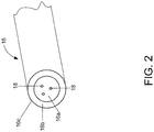
- the optical fiber 16 may include quantum dots 18 in one or more regions of the optical fiber.
- the optical fiber 16 may include a core 16a surrounded by cladding 16b having a different coefficient of refraction than the core so as to largely confine the signals propagating through the core within the core.
- the quantum dots 18 are included within the core 16a of the optical fiber 16.
- the quantum dots 18 within the core 16a of the optical fiber 16 may serve to amplify signals propagating through the core of the optical fiber and to enhance the sensitivity of the optical fiber to defects within the composite material.
- the optical fiber 16 may include quantum dots at the interface between the core 16a and the cladding 16b.
- the optical fiber 16 may include the quantum dots 18 within the cladding 16b, thereby enhancing the interaction of the signals propagating through the optical fiber with the surrounding composite material via fiber evanescent waves.
- the optical fiber 16 may include a plurality of quantum dots 18 on the outer surface 16c of the optical fiber, such as the outer surface of the cladding.
- the plurality of quantum dots 18 disposed upon the outer surface of the optical fiber 16 may interact more strongly with the local strain field in the composite material via evanescent waves.
- the optical fiber 16 may include the plurality of quantum dots 18 in only one of these regions, that is, only one of the core 16a, the cladding 16b or the outer surface 16c of the optical fiber.
- the optical fiber 16 may include the plurality of the quantum dots 18 in any two of these regions, such as any two of the core 16a, the cladding 16b or the outer surface 16c of the optical fiber or, in some examples, may include the plurality of quantum dots in all three of these regions, that is, in each of the core, the cladding, and the outer surface of the optical fiber.
- the optical fiber 16 may be a gradient index fiber that includes quantum dots 18 such that reference herein to the core of an optical fiber including quantum dots is also intended to encompass the example in which a gradient index fiber includes quantum dots.
- the optical fiber 16 may be a light pipe having a hollow core for supporting the propagation of infrared (IR) or other signals therealong.
- the optical fiber 16 may also include a plurality of quantum dots 18.
- the plurality of quantum dots 18 may be disposed upon an inner surface of the light pipe that faces and defines the hollow core.
- optical fibers 16 are described above, the foregoing examples are not meant to be all inclusive and other types of optical fibers may be employed including elliptical core optical fibers, multi-hole optical fibers, multi-core optical fibers and optical fibers having a myriad of other internal or surface structures that can impact the environment of any nearby quantum dots disposed within or on the optical fiber.
- the optical fiber may include quantum dots in a relatively uniform manner along its length or may only include quantum dots in one or more discrete segments along the length of the optical fiber.
- the optical fiber 16 may be more sensitive to defects in the composite material that are proximate to a segment of the optical fiber that includes quantum dots 18 relative to a segment of the optical fiber that does not include quantum dots.
- a system not only includes the composite structure 10 including the composite material and the embedded optical fiber 16, but also includes a signal source 20, such as an optical source, for providing signals to the optical fiber for propagation therealong.
- the signal source 20 may be configured to introduce signals via the first end of the optical fiber 16 for propagation along the length of the optical fiber toward the second end of the optical fiber.
- the system may include various types of signal sources 20 for introducing various types of signals for propagation along the optical fiber
- the signal source of one embodiment is a laser, such as a pulsed laser, for providing laser signals to the optical fiber 16 for propagation therethrough.
- the signal source 20 may be an IR signal source for providing IR signals to the first end of the optical fiber.
- the signal source 20 may provide the signals directly to the optical fiber 16, such as to the first end of the optical fiber. As shown in Figure 3 , however, the signals generated by the signal source may be conditioned prior to being delivered to the optical fiber 16.
- the system may include a wavelength selection device 22, such as a wavelength filter, for filtering the signals generated by the signal source 20 to insure that signals having only one or more predefined frequencies or a predefined range of frequency pass through the wavelength selection device for delivery to the optical fiber 16.
- the system may also include a polarization device 24, such as a Glan Taylor prism, a Glan Thompson prism, a Wollaston prism, a thin film polarizer, in combination with waveplates, including thin film devices or optically active materials, such as quartz, for limiting the signals that propagate beyond the polarization device to those having one or more predefined polarizations.
- a polarization device such as a Glan Taylor prism, a Glan Thompson prism, a Wollaston prism, a thin film polarizer, in combination with waveplates, including thin film devices or optically active materials, such as quartz, for limiting the signals that propagate beyond the polarization device to those having one or more predefined polarizations.
- the system may include an intensity filter 26, such as a neutral density filter, a color filter, variable attenuation devices such as wedge pairs or matched prisms, or other fixed or variable optical attenuation devices, for limiting the energy carried by the signals that are to be provided to the
- the system of the illustrated example includes each of the wavelength selection device 22, the polarization sensitive device 24 and the intensity filter 26, the system may include any one or any combination of these elements in other embodiments.
- the system may also include an optical device 28, such as a lens, for focusing the signals upon the first end of the optical fiber 16, such as by matching the signals to the numerical aperture of the optical fiber.
- the system also includes a detector 30 configured to receive the signals including any non-linear effects generated from the signals following propagation through the optical fiber 16, such as following fabrication of the composite structure 10 such that the composite structure is as-cured or during the fabrication of the composite structure so as to provide in-process monitoring.
- the detector 30 may be positioned so as to receive the signals exiting from the second end of the optical fiber 16, opposite the first end into which the signals from the signal source 20 are introduced into the optical fiber. In the illustrated example, however, the system is configured such that the signals are reflected and returned to the first end of the optical fiber 16.
- the detector 30 of this example may be positioned so as to receive the signals as well as non-linear effects created by the signals upon their exit from the first end of the optical fiber 16.
- the detector 30 may be positioned so as to receive the signals as well as non-linear effects created by the signals upon their exit from the first end of the optical fiber 16.
- a beam splitter 34 may be positioned to receive the reflected signals and to redirect the reflected signals that exit the first end of the optical fiber 16 to the detector 30.
- the detector 30 may receive the signals exiting the first end of the optical fiber 16 even though the detector is offset or out of linear alignment with the optical fiber, thereby facilitating the introduction of the signals from the signal source 20 into the first end of the optical fiber without being obstructed by the detector.
- the system may include various types of detectors including a solid state detector, such as a photodiode.
- the detector may be formed of a material that is selected and based upon the wavelength of the signals to be detected since, for example, semiconductor photodiodes generally detect signals having a predefined range of wavelengths that can be absorbed by the semiconductor material.
- a silicon photodiode may be utilized to detect the returning signals and the associated non-linear effects.
- the detector may include an avalanche photodiode (APD).
- the signals propagating along the optical fiber 16 may be reflected in various manners.
- the system may include a reflector 32, such as a mirror, for receiving the signals reaching the second end of the optical fiber 16 and for reflecting the signals such that the signals and the associated non-linear effects are returned to the optical fiber and propagate from the second end toward the first end for receipt and detection by the detector 30.
- the optical fiber 16 may include a Bragg grating 36 or other types of reflectors such as partially reflecting mirrors, e.g., a Fabry-Perot etalon having one or more partially reflecting mirrors, formed within the optical fiber, such as described in U.S. Patent No.
- quantum dots 18 may be disposed on or within the mirror in one example.
- defects within the composite material may affect the signals propagating along the optical fiber 16, such as by altering the magnitude and/or phase of the signals.
- defects in the composite material that cause the optical fiber 16 to be bent or to otherwise subject the optical fiber to stress or strain such as due to displacement of the structural elements 14 within the composite material, ply waviness, marcelling or like, may cause a change in the signals propagating along the optical fiber.
- defects within the composite material may be identified. For example, defects involving the deviation of in the path of a fiber tow or the position of a composite ply may be identified based upon the signals returning from the optical fiber 16. Some defects within the composite material may not only alter the properties of the optical signals propagating along the optical fiber 16, but may also cause the signals, or at least some of the signals, to be reflected. As such, the detector 30 of this example may not simply detect the signals that return to the first end of the optical fiber 16, but may also determine the time at which the reflected signals return to the first end of the optical fiber.
- the detector 30 and/or an associated time domain reflectometer may determine the relative location along the length of the optical fiber at which the defect is located, thereby directing further inspection of the composite material and/or repair of the composite material to the location in question.
- the optical fiber 16 includes a plurality of quantum dots 18.
- the plurality of the quantum dots 18 create a non-linear effect in response to a defect in the composite material.
- the quantum dots may create a variety of non-linear effects including a second order effect, such as the generation of a second harmonic.
- the second order effects such as a generation of a second harmonic, that is generated by the plurality of quantum dots 18 of one example may be strongly affected by the lack of centrosymmetry caused by the presence of defects within the composite material, such as by defects occasioned by changes in the placement and positioning of the structural elements 14.
- the quantum dots may generate a third order effect, such as the generation of a third order harmonic.
- Quantum dots have nonlinear optical responses that are inherently nonlinear. Because of their small physical dimensions, and because their optical refractive index will differ from the surrounding media, there will be a local field enhancement of any light signal that propagates in their vicinity. Since nonlinear effects are dependent on light intensity, the local field enhancement caused by the quantum dots will increase the size of any nonlinear response. In addition to third harmonic generation, other enhanced effects may include parametric amplification, Raman scattering, and four wave mixing. In general, second order nonlinear effects are not allowed in centro-symmetric media. But the straining of the composite structure, coupled with the presence of the quantum dots, can break the material symmetry, allowing second order effects such as second harmonic generation, sum-frequency, and difference frequency generation.
- the non-linear effects created in response to a defect in the composite material may serve as a reliable and discernable indicator of the defect.
- These non-linear effects may also propagate through the optical fiber 16 and be detected by the detector 30.
- the non-linear effects created by the plurality of quantum dots 18 may be of a magnitude that is sufficient to be readily identifiable by the detector 30 and to thereby serve as a reliable indicator of the defect within the composite material.
- the detector 30 may readily identify the non-linear effects since the non-linear effects are less likely to be adversely impacted by noise, which may impair the detection and evaluation of the primary signals, particularly in instances having a relatively low signal to noise ratio (SNR).
- SNR signal to noise ratio
- an optical fiber 16 including a plurality of quantum dots 18 may be embedded within a composite structure 10. Once the optical fiber 16 has been embedded in the composite structure 10, signals may be provided to the optical fiber for propagation there along. See block 42. Signals exiting the optical fiber 16 may then be detected. See block 44.
- Figure 5 depicts a method in which signals are provided to an optical fiber 16 that is embedded within a composite structure 10 for propagation there along. See block 50. The optical fiber 16 includes a plurality of quantum dots 18. Signals exiting the optical fiber 16 may then be detected. See block 52.
- embodiments of the method may be employed in conjunction with a composite structure 10 in an uncured state.
- an optical fiber 16 including a plurality of quantum dots 18 may be embedded within a composite structure 10 in an uncured state.
- signals may be provided to the optical fiber for propagation there along until the composite structure achieves a cured state. See block 62.
- Signals exiting the optical fiber 16 may then be detected until the composite structure 10 achieves the cured state. See block 64.
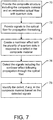
- a method may therefore be provided for monitoring the health of a composite structure 10 as shown, for example, in the flowchart of Figure 7 .
- the system and method of embodiments of the present disclosure may monitor the health of the composite structure during its fabrication prior to curing or other solidification of the resin, thereby providing in-process monitoring.
- the system and method of one embodiment could monitor a composite structure that did not cure or solidify in order to monitor the orientation of the plies or fiber tows.
- the composite structure 10 including a composite material and one or more optical fibers 16 disposed within the composite material may be provided, as shown in operation 70 of Figure 7 .
- the optical fiber 16 includes a plurality of quantum dots 18 for enhancing the non-linear optical properties of the optical fiber.
- signals may then be provided to the optical fiber 16 for propagation therealong, such as from a first end into which the signals are introduced toward an opposed second end.
- a defect in the composite material such as a defect that may cause the optical fibers to bend in an unanticipated manner or to otherwise result in unanticipated amounts of stress or strain being placed upon the optical fibers, a non-linear effect may be created by the plurality of quantum dots 18 as shown in operation 74.
- non-linear effects may be created including the creation of a second order effect, such as a generation of a second harmonic, the creation of a third order effect, such as a generation of a third order harmonic, or the like in response to the defect in the composite material.
- the method may also detect signals, including the non-linear effect following propagation through the optical fiber 16, as shown in operation 76. By analyzing the signals including the non-linear effect, such as by means of the detector 30 or a computer associated with and responsive to the detector, instances in which the composite material has a defect that has altered the signals propagating through the optical fiber 16 and has created non-linear effects may be identified. See operation 78.
- deviations in the path of a fiber tow and deviations in the position or path of a composite ply may be detected in accordance with one embodiment of the present disclosure. Additionally, the location of the defect may also be determined, such as based upon TDR, in some embodiments. Based upon the detection of a potential defect within the composite material, the method of one embodiment may provide for further testing and analysis of the potential defect and/or for making appropriate repairs to the composite material so as to repair the defect.
- the signals and the associated non-linear effects that are detected may be compared, such as by the detector 30 or an associated computer, to the signals and associated non-linear effects that are otherwise expected to be detected following propagation of the signal through the optical fiber 16 in an instance in which the composite material does not include any defects.
- the method may identify a potential defect within the composite material so as to allow for more detailed analysis and/or repair of the composite material or to inform the user of the need to alter the mission.
- the system and method of one embodiment may facilitate the detection of a defect within a composite material so as to permit the composite material to be further analyzed or inspected and/or to promote more focused repair of the composite material in a timely manner or otherwise respond to the new knowledge.
- the analysis of the non-linear effects created by the plurality of quantum dots 18 in response to a defect in the composite material may permit defects to be identified in a reliable manner that is not limited by the relatively low signal to noise ratio that may otherwise impair an analysis that is simply based upon the reflected signals within the optical fiber 16 without consideration of the associated non-linear effects.
- the health of a composite material may be monitored by embedding a plurality of optical fibers 16, such as an array of optical fibers, that include quantum dots 18 within the composite material.
- the signals and associated non-linear effects that are detected by detector 30 following signal propagation through the array of optical fibers may provide multi-dimensional data, such as two dimensional (2D) or three dimensional (3D) data indicative of the health of the composite material by providing, for example, an indication of deviations in the location of a fiber tow or composite ply and, in some embodiments utilizing optical time domain reflectometry, the location of such deviations.
- the detector 30 may be configured to display a visual representation of this multi-dimensional data, such as by overlaying a visual representation of the multi-dimensional data onto a model of the composite structure 10 that is being fabricated such that the model can provide a reference for the multi-dimensional data gathered by the system of this embodiment of the present disclosure.
Landscapes
- Physics & Mathematics (AREA)
- General Physics & Mathematics (AREA)
- Chemical & Material Sciences (AREA)
- Analytical Chemistry (AREA)
- General Health & Medical Sciences (AREA)
- Immunology (AREA)
- Pathology (AREA)
- Engineering & Computer Science (AREA)
- Biochemistry (AREA)
- Health & Medical Sciences (AREA)
- Life Sciences & Earth Sciences (AREA)
- Aviation & Aerospace Engineering (AREA)
- Electromagnetism (AREA)
- Mechanical Engineering (AREA)
- Composite Materials (AREA)
- Optics & Photonics (AREA)
- Investigating Materials By The Use Of Optical Means Adapted For Particular Applications (AREA)
- Length Measuring Devices By Optical Means (AREA)
- Investigating Or Analysing Materials By Optical Means (AREA)
- Testing Of Devices, Machine Parts, Or Other Structures Thereof (AREA)
- Testing Of Optical Devices Or Fibers (AREA)
- Optical Transform (AREA)
- Measuring Temperature Or Quantity Of Heat (AREA)
- Optical Fibers, Optical Fiber Cores, And Optical Fiber Bundles (AREA)
Description
- Embodiments of the present disclosure relate generally to composite structures and, more particularly, to composite structures having embedded sensing systems for monitoring the health of a composite material.
- Composite structures are structures consisting of two or more components often with some imparted order which are utilized in a wide variety of applications. For example, air vehicles, such as aircraft, spacecraft or the like, may utilize composite structures in order to take advantage of the benefits attributable to the increased strength-to-weight ratio offered by composite materials. Other applications that may include composite structures include other types of vehicles, such as automobiles, marine vehicles, bicycles and the like, as well as a wide variety of other structures, such as buildings, bridges, etc. Composite structures may also be produced and used with additional functionalities including altered thermal, electrical, acoustical, or mechanical properties by suitably modifying the materials used, the structure itself, or the process used to produce the structure.
- Composite structures may be fabricated in various manners designed to impart a predetermined order to a plurality of elements dispersed within a resin or other mostly continuous medium, e.g., polymer, glass, or cement. Typically, a composite structure includes a plurality of structural fibers, such as glass fibers or other elements including carbon fibers, metalized carbon fibers, metal or polymer sheets, carbon or polymer veils, pre-impregnated composite sheets, woven sheets of fibers, matts of random or organized fibers, metal or polymer meshes, embedded in a resin matrix. The resin matrix may be any one of many thermoplastic or thermoset polymer combinations, adhesives or other bonding materials, or cement. Once the composite structure has been laid up, such as by placing a plurality of composite plies one upon another or by laying a plurality of composite tows one beside another, in a manner so as to have the desired shape or woven into a predetermined two dimensional (2D) or three dimensional (3D) structure, the composite structure may be cured, melted or bonded in one or more processing steps.
- While composite structures offer a number of advantages, composite structures may occasionally have various anomalies, such as delamination between composite plies, waviness within the composite plies or marcelling in which a composite tow rolls at least partially on top of itself so as to create an inner swirl within the composite structure. While some of these anomalies may be detected from a visual inspection of the composite structure, a number of the anomalies may reside within the interior of the composite structure so as not to be detected during a visual inspection of the composite structure. As such, a variety of inspection techniques utilizing, for example, x-rays, ultrasonic signals or the like have been developed in order to interrogate the interior of a composite structure. While these inspection techniques may detect a number of anomalies, such as ply delaminations, other anomalies that may be created by the misorientation or misplacement of the structural fibers within the resin of a composite structure may present more of a challenge from a detection standpoint.
- In this regard, the plurality of structural fibers or other elements within a composite structure generally extends in a predefined direction with the physical properties of the composite structure depending, at least in part, upon the directionality of the structural fibers or other elements. In some instances, however, the structural fibers or other elements within a composite structure may assume a different and an unintended orientation or position which may cause the physical properties of the composite structure to also be different. For example, the structural fibers or other included elements that extend proximate a resin-rich area may migrate or move toward or into the resin-rich area, thereby deviating from their intended orientation. The unintended orientation or position of the structural fibers may be the result of gravity, hydrostatic pressure, chemical or boiling action or mechanical action. Since this deviation in the orientation or position of the structural fibers or other elements may impact the physical properties of the composite structure, it would be desirable to detect such deviations in the orientation or position of the structural fibers or other elements as well as to detect other defects in the composite structure in a reliable manner such that appropriate repairs could be made, if so desired.
- Document
EP 1 519 181 A1 shows a damage detection system for a structural composite material comprising a vibration application apparatus including: a sheet body; a plurality of piezo elements sprinkled throughout and held by the sheet body; and wires for the piezo elements provided to the sheet body. The damage detection system also comprises: a fiber optic sensor which includes a grating portion in a core portion thereof, the grating portion reflecting light of a predetermined wavelength; a light source to perform light irradiation onto the core portion; and a characteristic detection unit to detect a characteristic of the light reflected from the grating portion. - Document
US 2008/0085086 A1 shows holey optical fibers, e.g. photonic fibers, random-hole fibers, fabricated with quantum dots disposed in the holes. - Therefore, a method for monitoring a composite structure during manufacture thereof according to claim 1 is provided.
- The method comprises: providing a composite structure; embedding an optical fiber within the composite structure in an uncured state, the optical fiber including a plurality of quantum dots, the plurality of quantum dots being configured to create a nonlinear effect in response to defect in the composite material; providing signals from a signal source to the optical fiber for propagation there along until the composite structure achieves a cured state, the signal source being configured to provide two distinct input frequencies v1 and v2, wherein at least one of v1, v2, v1 + v2 or v1-v2 is resonant with one or more material parameters of the optical fiber; detecting signals that exit the optical fiber until the composite structure achieves the cured state; identifying the presence of a non-linear effect in the detected signal; and identifying a defect in the composite structure in response to identifying the presence of the non-linear effect.
- In an aspect in which the optical fiber includes a core and a cladding surrounding the core, the core may include the plurality of quantum dots so to amplify signals propagating through the core and/or enhance the sensitivity of the optical fiber. Additionally or alternatively, the cladding of the optical fiber may include the plurality of quantum dots in order to enhance interaction with the surrounding resin via a fiber evanescent wave. Still further, the plurality of quantum dots may be disposed upon a surface of the optical fiber in order to provide for stronger interaction with the local strain field, material and evanescent wave. The method of one aspect also includes creating a non-linear effect, such as a second order effect, e.g., the generation of a second harmonic, with the plurality of quantum dots in response to a defect in the composite material. The method of this aspect also detects the signals, including the non-linear effect, following propagation through the optical fiber. Since the non-linear effect may be readily identified, the method of this aspect may reliably detect defects the composite material so as to facilitate further inspection or repair. If for example the signal source is positioned proximate the first end of the optical fiber, the method may also include reflecting the signals through the optical fiber from the second end toward the first end from which the signals were initially launched. In this aspect, the detection of the signals may include detecting the signals emitted by the first end of the optical fiber following reflection of the signals therethrough.
- In accordance with the present disclosure a method is provided in order to reliably identify defects within a composite material so as to permit further inspection or repair to be performed in an informed and efficient manner.
- Having thus described the example embodiments of the present disclosure in general terms, reference will now be made to the accompanying drawings, which are not necessarily drawn to scale, and wherein:
-
Figure 1 is a cross-sectional representation of a composite structure in accordance with one example of the present disclosure which illustrates a composite material and an embedded sensing system, including an optical fiber having a plurality of quantum dots that is disposed within the composite material; -
Figure 2 is a fragmentary perspective view of an optical fiber in accordance with one example of the present disclosure; -
Figure 3 is a schematic representation of a system for monitoring the health of a composite structure in accordance with one example of the present disclosure; -
Figures 4-6 are flow charts of methods in accordance with examples of the present disclosure; and -
Figure 7 is a flow chart of a method for monitoring the health of a composite structure in accordance with one embodiment of the present invention. - Referring now to
Figure 1 , acomposite structure 10 having an embedded sensing system in accordance with one embodiment of the present disclosure is illustrated. Thecomposite structure 10 may be utilized in a variety of applications including in air vehicles, such as aircraft, spacecraft or the like, land vehicles, such as automobiles, trucks, trailers, bicycles, etc., marine vehicles, buildings and other structures. As shown inFigure 1 , thecomposite structure 10 includes a composite material having a plurality ofstructural elements 12 embedded within a matrix ofresin 14. The composite material may include a number of different types ofstructural elements 12 including structural fibers such as glass fibers, carbon fibers or the like and other elements such as graphene sheets, a carbon veil, a woven prepreg, a solid sheet and a metal or polymer mesh. Additionally, the composite material may include a number of different types ofresin 14 including, for example, epoxy resin, polyester resin or the like. - In the illustrated example the composite material includes a plurality of composite plies, each having the plurality of
structural elements 12 embedded within the matrix ofresin 14. - The composite plies may be laid one upon the other as shown in
Figure 1 . However, the composite material may be fabricated in other manners including, for example, a plurality of composite tows that are laid beside one another or by including sheets, veils, pre-impregnated cloth, metal or polymer mesh or the like. During the fabrication of the composite material, the composite material is laid up or formed so as to have a desired shape, such as by laying the composite plies or composite tows or other elements upon a mandrel or tool having the desired shape. During the formation of the composite material, such as during the lay up or placement of the plurality of composite plies, composite tows or the like, and prior to curing of the composite material, one or moreoptical fibers 16 including a plurality ofquantum dots 18 is disposed within the composite material, such as by being embedded within the composite material, as also shown inFigure 1 . In this regard, theoptical fiber 16 is disposed within the composite material in such a manner that at least one end of the optical fiber and, more typically, both of the opposed ends of the optical fiber are accessible, such as by extending to an edge, such as opposed edges, of the composite material. While a singleoptical fiber 16 is shown inFigure 1 , thecomposite structure 10 may include a plurality of optical fibers which may, for example, extend parallel to one another through the composite material. - The
optical fiber 16 may be positioned between composite plies, composite tows, or the like. Once theoptical fiber 16 has been disposed within the composite material, the composite material may be cured or otherwise processed to solidify theresin 14 such that the composite material retains the shape in which the composite plies or composite tows were laid up. This curing or other solidification of the composite material also serves to secure theoptical fiber 16 within the composite material such that the optical fiber extends therethrough. - The
optical fiber 16 that is disposed within the composite material includes a plurality ofquantum dots 18. While a plurality ofquantum dots 18 are shown within theoptical fiber 16 ofFigure 1 , the quantum dots are illustrated to be larger than typical for purposes of illustration, but not of example. Theoptical fiber 16 of one example is formed to include thequantum dots 18 by implanting spectroscopically enhancing features within the optical fiber or by inducing microscopic structural changes within the optical fiber which cause enhancements to the hyperpolarizability of the optical fiber. As described below, the plurality ofquantum dots 18 enhance the non-linear optical properties of theoptical fiber 16 relative to a comparable optical fiber that does not include quantum dots. - In regards to the implantation of spectroscopically enhancing features or the inducement of microscopic structural changes within the optical fiber, it is noted that spectroscopic enhancement in the case of nonlinear optics diverges somewhat from the traditional linear case. In linear spectroscopy, light will be more readily absorbed by a material when the light frequency matches that associated with a material excitation. Once that light is absorbed, it may be re-emitted or thermalized within the material, depending on the rest of the material parameters.
- In the nonlinear case, it is not necessary for all or any of the light input frequencies to coincide with material excitations to produce a spectroscopic enhancement of the effect in question. In one case, for example, there may be two inputs, one of which is resonant with a material parameter, and the other not resonant. At the sum-frequency of the two inputs, there will be an enhancement of the efficiency of sum-frequency production, even though there is no absorption, per se, in the material. In another case, neither of the two inputs may coincide with a material excitation, but if the frequency difference coincides with a material excitation, the efficiency of light production at the difference frequency will be enhanced. Alternately, the case of second harmonic generation may have an input signal that is not resonant, but if the second harmonic frequency coincides with a material excitation, the second harmonic generation process will be enhanced.
- There will be naturally occurring material excitations associated with any optical fiber or quantum dot materials. As such, the input frequencies to the optical fiber may be selected to allow the nonlinear processes to be resonant with one of more of the material excitations. For example, if there are two distinct input frequencies v1 and v2, then v1 can be resonant, or v2 can be resonant, or v1 + v2 can be resonant, or v1 - v2 can be resonant with one or more of the material parameters. Additionally, several of the combinations may be resonant simultaneously. In the second harmonic case, there is a single frequency input at v1 with either v1 being resonant or 2v1 (v1 + v1) being resonant. Alternately, the optical fiber with the quantum dots can be doped with materials that provide a material resonance. The material with which the optical fiber is doped could be, but is not limited to, atomic or molecular species that have known spectral features.
- Alternately, microscopic structural changes not involving material excitations can lead to nonlinear signal enhancements. In this regard, a fiber that is physically strained will have local molecular bonds strained. In this regard, it has been established that straining molecular bonds will increase their nonlinear response through a larger hyperpolarizibility. In addition, a physically strained material will have a net orientation introduced at a molecular level which will also increase the net cumulative effect of the hyperpolarizibility. The combination of these two effects will lead to a larger nonlinear optical response, even if pure spectroscopic enhancements are unavailable.
- The
optical fiber 16 may includequantum dots 18 in one or more regions of the optical fiber. As shown inFigure 2 , for example, theoptical fiber 16 may include acore 16a surrounded by cladding 16b having a different coefficient of refraction than the core so as to largely confine the signals propagating through the core within the core. In the illustrated example, thequantum dots 18 are included within thecore 16a of theoptical fiber 16. In this example, thequantum dots 18 within thecore 16a of theoptical fiber 16 may serve to amplify signals propagating through the core of the optical fiber and to enhance the sensitivity of the optical fiber to defects within the composite material. In an alternative example, theoptical fiber 16 may include quantum dots at the interface between the core 16a and thecladding 16b. In yet another example, theoptical fiber 16 may include thequantum dots 18 within thecladding 16b, thereby enhancing the interaction of the signals propagating through the optical fiber with the surrounding composite material via fiber evanescent waves. In a further example, theoptical fiber 16 may include a plurality ofquantum dots 18 on theouter surface 16c of the optical fiber, such as the outer surface of the cladding. In this example, the plurality ofquantum dots 18 disposed upon the outer surface of theoptical fiber 16 may interact more strongly with the local strain field in the composite material via evanescent waves. Theoptical fiber 16 may include the plurality ofquantum dots 18 in only one of these regions, that is, only one of thecore 16a, thecladding 16b or theouter surface 16c of the optical fiber. Alternatively, theoptical fiber 16 may include the plurality of thequantum dots 18 in any two of these regions, such as any two of thecore 16a, thecladding 16b or theouter surface 16c of the optical fiber or, in some examples, may include the plurality of quantum dots in all three of these regions, that is, in each of the core, the cladding, and the outer surface of the optical fiber. - In another example, the
optical fiber 16 may be a gradient index fiber that includesquantum dots 18 such that reference herein to the core of an optical fiber including quantum dots is also intended to encompass the example in which a gradient index fiber includes quantum dots. In yet another example, theoptical fiber 16 may be a light pipe having a hollow core for supporting the propagation of infrared (IR) or other signals therealong. In this example, theoptical fiber 16 may also include a plurality ofquantum dots 18. For example, the plurality ofquantum dots 18 may be disposed upon an inner surface of the light pipe that faces and defines the hollow core. Although several types ofoptical fibers 16 are described above, the foregoing examples are not meant to be all inclusive and other types of optical fibers may be employed including elliptical core optical fibers, multi-hole optical fibers, multi-core optical fibers and optical fibers having a myriad of other internal or surface structures that can impact the environment of any nearby quantum dots disposed within or on the optical fiber. - Regardless of type of
optical fiber 16 and/or the region(s) of the optical fiber that includes thequantum dots 18, the optical fiber may include quantum dots in a relatively uniform manner along its length or may only include quantum dots in one or more discrete segments along the length of the optical fiber. In this regard, theoptical fiber 16 may be more sensitive to defects in the composite material that are proximate to a segment of the optical fiber that includesquantum dots 18 relative to a segment of the optical fiber that does not include quantum dots. - As noted above and as shown in more detail in
Figure 3 , at least one end of theoptical fiber 16 and, more typically, both of the opposed first and second ends of the optical fiber are accessible, such as by extending beyond or at least to an edge of a composite material. As shown in the example ofFigure 3 , a system not only includes thecomposite structure 10 including the composite material and the embeddedoptical fiber 16, but also includes asignal source 20, such as an optical source, for providing signals to the optical fiber for propagation therealong. In this regard, thesignal source 20 may be configured to introduce signals via the first end of theoptical fiber 16 for propagation along the length of the optical fiber toward the second end of the optical fiber. Although the system may include various types ofsignal sources 20 for introducing various types of signals for propagation along the optical fiber, the signal source of one embodiment is a laser, such as a pulsed laser, for providing laser signals to theoptical fiber 16 for propagation therethrough. In another example in which theoptical fiber 16 is a light pipe, thesignal source 20 may be an IR signal source for providing IR signals to the first end of the optical fiber. - The
signal source 20 may provide the signals directly to theoptical fiber 16, such as to the first end of the optical fiber. As shown inFigure 3 , however, the signals generated by the signal source may be conditioned prior to being delivered to theoptical fiber 16. For example, the system may include awavelength selection device 22, such as a wavelength filter, for filtering the signals generated by thesignal source 20 to insure that signals having only one or more predefined frequencies or a predefined range of frequency pass through the wavelength selection device for delivery to theoptical fiber 16. The system may also include apolarization device 24, such as a Glan Taylor prism, a Glan Thompson prism, a Wollaston prism, a thin film polarizer, in combination with waveplates, including thin film devices or optically active materials, such as quartz, for limiting the signals that propagate beyond the polarization device to those having one or more predefined polarizations. Further, the system may include anintensity filter 26, such as a neutral density filter, a color filter, variable attenuation devices such as wedge pairs or matched prisms, or other fixed or variable optical attenuation devices, for limiting the energy carried by the signals that are to be provided to theoptical fiber 16 to ensure that the optical fiber is not damaged by signals having excessively high energy levels. Although the system of the illustrated example includes each of thewavelength selection device 22, the polarizationsensitive device 24 and theintensity filter 26, the system may include any one or any combination of these elements in other embodiments. As shown inFigure 3 , the system may also include anoptical device 28, such as a lens, for focusing the signals upon the first end of theoptical fiber 16, such as by matching the signals to the numerical aperture of the optical fiber. - As also shown in
Figure 3 , the system also includes adetector 30 configured to receive the signals including any non-linear effects generated from the signals following propagation through theoptical fiber 16, such as following fabrication of thecomposite structure 10 such that the composite structure is as-cured or during the fabrication of the composite structure so as to provide in-process monitoring. In one example, thedetector 30 may be positioned so as to receive the signals exiting from the second end of theoptical fiber 16, opposite the first end into which the signals from thesignal source 20 are introduced into the optical fiber. In the illustrated example, however, the system is configured such that the signals are reflected and returned to the first end of theoptical fiber 16. As such, thedetector 30 of this example may be positioned so as to receive the signals as well as non-linear effects created by the signals upon their exit from the first end of theoptical fiber 16. By constructing the system such that thedetector 30 receives reflected signals from the first end of theoptical fiber 16, a majority of the components of the system may be co-located, thereby potentially simplifying the design and installation of the components. - As shown in
Figure 3 , abeam splitter 34 may be positioned to receive the reflected signals and to redirect the reflected signals that exit the first end of theoptical fiber 16 to thedetector 30. By including thebeam splitter 34, thedetector 30 may receive the signals exiting the first end of theoptical fiber 16 even though the detector is offset or out of linear alignment with the optical fiber, thereby facilitating the introduction of the signals from thesignal source 20 into the first end of the optical fiber without being obstructed by the detector. The system may include various types of detectors including a solid state detector, such as a photodiode. The detector may be formed of a material that is selected and based upon the wavelength of the signals to be detected since, for example, semiconductor photodiodes generally detect signals having a predefined range of wavelengths that can be absorbed by the semiconductor material. In one embodiment, a silicon photodiode may be utilized to detect the returning signals and the associated non-linear effects. In order to provide for increased sensitivity, such as to facilitate detection of the non-linear effects which may be smaller than the reflected signals, the detector may include an avalanche photodiode (APD). - The signals propagating along the
optical fiber 16 may be reflected in various manners. For example, the system may include areflector 32, such as a mirror, for receiving the signals reaching the second end of theoptical fiber 16 and for reflecting the signals such that the signals and the associated non-linear effects are returned to the optical fiber and propagate from the second end toward the first end for receipt and detection by thedetector 30. Additionally, or alternatively, theoptical fiber 16 may include a Bragg grating 36 or other types of reflectors such as partially reflecting mirrors, e.g., a Fabry-Perot etalon having one or more partially reflecting mirrors, formed within the optical fiber, such as described inU.S. Patent No. 5,682,237 , for reflecting at least a portion of the signals and the associated non-linear effects that are propagating along the optical fiber. In an instance in which theoptical fiber 16 includes a partially reflecting mirror,quantum dots 18 may be disposed on or within the mirror in one example. In accordance with an example, defects within the composite material may affect the signals propagating along theoptical fiber 16, such as by altering the magnitude and/or phase of the signals. For example, defects in the composite material that cause theoptical fiber 16 to be bent or to otherwise subject the optical fiber to stress or strain, such as due to displacement of thestructural elements 14 within the composite material, ply waviness, marcelling or like, may cause a change in the signals propagating along the optical fiber. By detecting the signal following propagation through theoptical fiber 16 and by identifying any changes in the signal, defects within the composite material may be identified. For example, defects involving the deviation of in the path of a fiber tow or the position of a composite ply may be identified based upon the signals returning from theoptical fiber 16. Some defects within the composite material may not only alter the properties of the optical signals propagating along theoptical fiber 16, but may also cause the signals, or at least some of the signals, to be reflected. As such, thedetector 30 of this example may not simply detect the signals that return to the first end of theoptical fiber 16, but may also determine the time at which the reflected signals return to the first end of the optical fiber. By determining the time difference between the time at which the signals were launched into the first end of theoptical fiber 16 and the time at which the reflected signals exited from the first end of the optical fiber as well as the speed at which the signals propagate through the optical fiber, thedetector 30 and/or an associated time domain reflectometer (TDR) may determine the relative location along the length of the optical fiber at which the defect is located, thereby directing further inspection of the composite material and/or repair of the composite material to the location in question. - As described above, the
optical fiber 16 includes a plurality ofquantum dots 18. The plurality of thequantum dots 18 create a non-linear effect in response to a defect in the composite material. For example, the quantum dots may create a variety of non-linear effects including a second order effect, such as the generation of a second harmonic. In this regard, the second order effects, such as a generation of a second harmonic, that is generated by the plurality ofquantum dots 18 of one example may be strongly affected by the lack of centrosymmetry caused by the presence of defects within the composite material, such as by defects occasioned by changes in the placement and positioning of thestructural elements 14. Additionally, or alternatively, the quantum dots may generate a third order effect, such as the generation of a third order harmonic. Quantum dots have nonlinear optical responses that are inherently nonlinear. Because of their small physical dimensions, and because their optical refractive index will differ from the surrounding media, there will be a local field enhancement of any light signal that propagates in their vicinity. Since nonlinear effects are dependent on light intensity, the local field enhancement caused by the quantum dots will increase the size of any nonlinear response. In addition to third harmonic generation, other enhanced effects may include parametric amplification, Raman scattering, and four wave mixing. In general, second order nonlinear effects are not allowed in centro-symmetric media. But the straining of the composite structure, coupled with the presence of the quantum dots, can break the material symmetry, allowing second order effects such as second harmonic generation, sum-frequency, and difference frequency generation. As such, by including a plurality ofquantum dots 18 within theoptical fiber 16, the non-linear effects created in response to a defect in the composite material, such as a defect that causes an unanticipated bending of the optical fiber, may serve as a reliable and discernable indicator of the defect. These non-linear effects may also propagate through theoptical fiber 16 and be detected by thedetector 30. Indeed, the non-linear effects created by the plurality ofquantum dots 18 may be of a magnitude that is sufficient to be readily identifiable by thedetector 30 and to thereby serve as a reliable indicator of the defect within the composite material. Further, thedetector 30 may readily identify the non-linear effects since the non-linear effects are less likely to be adversely impacted by noise, which may impair the detection and evaluation of the primary signals, particularly in instances having a relatively low signal to noise ratio (SNR). - Various methods may be provided in accordance with the following examples. As shown in
block 40 ofFigure 4 , anoptical fiber 16 including a plurality ofquantum dots 18 may be embedded within acomposite structure 10. Once theoptical fiber 16 has been embedded in thecomposite structure 10, signals may be provided to the optical fiber for propagation there along. Seeblock 42. Signals exiting theoptical fiber 16 may then be detected. Seeblock 44. Similarly,Figure 5 depicts a method in which signals are provided to anoptical fiber 16 that is embedded within acomposite structure 10 for propagation there along. Seeblock 50. Theoptical fiber 16 includes a plurality ofquantum dots 18. Signals exiting theoptical fiber 16 may then be detected. Seeblock 52. In addition to or instead of employing the method in conjunction with composite materials that have been cured, embodiments of the method may be employed in conjunction with acomposite structure 10 in an uncured state. As shown inblock 60 ofFigure 6 , for example, anoptical fiber 16 including a plurality ofquantum dots 18 may be embedded within acomposite structure 10 in an uncured state. Once theoptical fiber 16 has been embedded in thecomposite structure 10, signals may be provided to the optical fiber for propagation there along until the composite structure achieves a cured state. Seeblock 62. Signals exiting theoptical fiber 16 may then be detected until thecomposite structure 10 achieves the cured state. Seeblock 64. - According to the invention, a method may therefore be provided for monitoring the health of a
composite structure 10 as shown, for example, in the flowchart ofFigure 7 . While the health of thecomposite structure 10 may be monitored following its fabrication, such as in an as-cured state, the system and method of embodiments of the present disclosure may monitor the health of the composite structure during its fabrication prior to curing or other solidification of the resin, thereby providing in-process monitoring. Indeed, the system and method of one embodiment could monitor a composite structure that did not cure or solidify in order to monitor the orientation of the plies or fiber tows. In this regard, thecomposite structure 10 including a composite material and one or moreoptical fibers 16 disposed within the composite material may be provided, as shown inoperation 70 ofFigure 7 . Theoptical fiber 16 includes a plurality ofquantum dots 18 for enhancing the non-linear optical properties of the optical fiber. As shown inoperation 72, signals may then be provided to theoptical fiber 16 for propagation therealong, such as from a first end into which the signals are introduced toward an opposed second end. In response to a defect in the composite material, such as a defect that may cause the optical fibers to bend in an unanticipated manner or to otherwise result in unanticipated amounts of stress or strain being placed upon the optical fibers, a non-linear effect may be created by the plurality ofquantum dots 18 as shown inoperation 74. Various non-linear effects may be created including the creation of a second order effect, such as a generation of a second harmonic, the creation of a third order effect, such as a generation of a third order harmonic, or the like in response to the defect in the composite material. The method may also detect signals, including the non-linear effect following propagation through theoptical fiber 16, as shown inoperation 76. By analyzing the signals including the non-linear effect, such as by means of thedetector 30 or a computer associated with and responsive to the detector, instances in which the composite material has a defect that has altered the signals propagating through theoptical fiber 16 and has created non-linear effects may be identified. Seeoperation 78. With respect to the defects that may be detected, deviations in the path of a fiber tow and deviations in the position or path of a composite ply may be detected in accordance with one embodiment of the present disclosure. Additionally, the location of the defect may also be determined, such as based upon TDR, in some embodiments. Based upon the detection of a potential defect within the composite material, the method of one embodiment may provide for further testing and analysis of the potential defect and/or for making appropriate repairs to the composite material so as to repair the defect. - In this regard, the signals and the associated non-linear effects that are detected may be compared, such as by the
detector 30 or an associated computer, to the signals and associated non-linear effects that are otherwise expected to be detected following propagation of the signal through theoptical fiber 16 in an instance in which the composite material does not include any defects. In an instance in which the signals and/or the non-linear effects deviate, such as by at least a predetermined amount or percentage, the method may identify a potential defect within the composite material so as to allow for more detailed analysis and/or repair of the composite material or to inform the user of the need to alter the mission. - By enhancing the non-linear properties of the
optical fiber 16 by the inclusion of a plurality ofquantum dots 18, the impact of a defect within the composite material on the signals propagating through the optical fiber is correspondingly enhanced. In this regard, the non-linear effects created by the plurality ofquantum dots 18 in response to a defect within the composite material are sufficiently repeatable and of a magnitude that may be reliably identified by adetector 30. Thus, the system and method of one embodiment may facilitate the detection of a defect within a composite material so as to permit the composite material to be further analyzed or inspected and/or to promote more focused repair of the composite material in a timely manner or otherwise respond to the new knowledge. Indeed, the analysis of the non-linear effects created by the plurality ofquantum dots 18 in response to a defect in the composite material may permit defects to be identified in a reliable manner that is not limited by the relatively low signal to noise ratio that may otherwise impair an analysis that is simply based upon the reflected signals within theoptical fiber 16 without consideration of the associated non-linear effects. - As indicated above, the health of a composite material may be monitored by embedding a plurality of
optical fibers 16, such as an array of optical fibers, that includequantum dots 18 within the composite material. The signals and associated non-linear effects that are detected bydetector 30 following signal propagation through the array of optical fibers may provide multi-dimensional data, such as two dimensional (2D) or three dimensional (3D) data indicative of the health of the composite material by providing, for example, an indication of deviations in the location of a fiber tow or composite ply and, in some embodiments utilizing optical time domain reflectometry, the location of such deviations. In one embodiment, thedetector 30 may be configured to display a visual representation of this multi-dimensional data, such as by overlaying a visual representation of the multi-dimensional data onto a model of thecomposite structure 10 that is being fabricated such that the model can provide a reference for the multi-dimensional data gathered by the system of this embodiment of the present disclosure.
Claims (5)
- A method for monitoring a composite structure (10) during manufacture thereof, the method comprising:providing (70) the composite structure (10);embedding an optical fiber (16) within the composite structure (10) in an uncured state, the optical fiber (16) including a plurality of quantum dots (18), the plurality of quantum dots (18) being configured to create (74) a nonlinear effect in response to a defect in the composite material (10);providing (72) signals from a signal source (20) to the optical fiber (16) for propagation there along until the composite structure (10) achieves a cured state, the signal source (20) being configured to provide two distinct input frequencies v1 and v2, wherein at least one of v1, v2, v1 + v2 or v1-v2 is resonant with one or more material parameters of the optical fiber (16);detecting (76) signals that exit the optical fiber (16) until the composite structure (10) achieves the cured state;identifying the presence of a non-linear effect in the detected signal; andidentifying (78) a defect in the composite structure (10) in response to identifying the presence of the non-linear effect.
- A method according to claim 1 wherein the optical fiber (16) comprises a core and a cladding surrounding the core, and wherein the core comprises the plurality of quantum dots (18).
- A method according to claim 1 wherein the optical fiber (16) comprises a core and a cladding surrounding the core, and wherein the cladding comprises the plurality of quantum dots (18).
- A method according to claim 1 wherein the plurality of quantum dots (18) are disposed upon a surface of the optical fiber (16) .
- A method according to claim 1 wherein creating (74) a nonlinear effect comprises creating a second order effect in response to the defect in the composite material (10).
Applications Claiming Priority (1)
| Application Number | Priority Date | Filing Date | Title |
|---|---|---|---|
| US13/562,832 US9170172B2 (en) | 2011-08-23 | 2012-07-31 | Composite structure having an embedded sensing system |
Publications (3)
| Publication Number | Publication Date |
|---|---|
| EP2693187A2 EP2693187A2 (en) | 2014-02-05 |
| EP2693187A3 EP2693187A3 (en) | 2016-02-24 |
| EP2693187B1 true EP2693187B1 (en) | 2018-09-05 |
Family
ID=48782191
Family Applications (1)
| Application Number | Title | Priority Date | Filing Date |
|---|---|---|---|
| EP13174925.1A Active EP2693187B1 (en) | 2012-07-31 | 2013-07-03 | Composite structure having an embedded sensing system |
Country Status (7)
| Country | Link |
|---|---|
| EP (1) | EP2693187B1 (en) |
| JP (1) | JP6226612B2 (en) |
| KR (1) | KR102022728B1 (en) |
| CN (1) | CN103575740B (en) |
| BR (1) | BR102013019350B1 (en) |
| CA (1) | CA2815788C (en) |
| RU (1) | RU2641638C2 (en) |
Cited By (1)
| Publication number | Priority date | Publication date | Assignee | Title |
|---|---|---|---|---|
| US10424056B2 (en) | 2018-02-22 | 2019-09-24 | The Boeing Company | Active real-time characterization system for monitoring absorption and curing rates of chemical substances |
Families Citing this family (12)
| Publication number | Priority date | Publication date | Assignee | Title |
|---|---|---|---|---|
| CN103913577A (en) * | 2014-03-07 | 2014-07-09 | 吉林出入境检验检疫局检验检疫技术中心 | Method used for detecting escherichia coli O157:H7 based on optical fiber evanescent wave biosensor |
| CN103901210A (en) * | 2014-03-07 | 2014-07-02 | 吉林出入境检验检疫局检验检疫技术中心 | Listeria monocytogenes detecting method based on optical fiber evanescent wave biosensor |
| CN104315990B (en) * | 2014-10-31 | 2017-08-01 | 山东大学 | A kind of test device of polymer matrix composites hot moulding curing deformation and the preparation and application of device |
| JP6346214B2 (en) * | 2016-03-24 | 2018-06-20 | 株式会社Subaru | Composite material forming jig, composite material forming method, ultrasonic inspection system, ultrasonic inspection method, and aircraft structure |
| US10337935B2 (en) | 2016-12-12 | 2019-07-02 | Sikorsky Aircraft Corporation | Systems and methods for integrated, multi-functional, fault tolerant sensing and communication |
| CN108982427A (en) * | 2018-10-15 | 2018-12-11 | 中国计量大学 | Spherical welding long-period fiber grating surface plasma body resonant vibration hydrogen sensor |
| WO2020100509A1 (en) | 2018-11-12 | 2020-05-22 | 日本電気株式会社 | Civil engineering structure monitoring system, civil engineering structure monitoring device, civil engineering structure monitoring method, and non-transitory computer-readable medium |
| RU192790U1 (en) * | 2019-06-21 | 2019-10-01 | Общество с ограниченной ответственностью "Квантум-Центр" | FIBER OPTICAL MOVEMENT SENSOR |
| US11611029B2 (en) | 2020-05-21 | 2023-03-21 | Saudi Arabian Oil Company | Methods to harvest thermal energy during subsurface high power laser transmission |
| CN114397279B (en) * | 2022-01-19 | 2023-07-18 | 天津大学 | Strain state detection method for two-dimensional material and strained object under any strain state |
| CN114383805B (en) * | 2022-03-23 | 2022-05-31 | 中国空气动力研究与发展中心超高速空气动力研究所 | Measurement system and measurement method of discharge drag reduction equipment |
| FR3135140A1 (en) * | 2022-04-28 | 2023-11-03 | Epsilon Composite | DEVICE FOR DETECTING A DEFECT IN A STRUCTURAL ELEMENT MADE OF COMPOSITE MATERIAL |
Citations (1)
| Publication number | Priority date | Publication date | Assignee | Title |
|---|---|---|---|---|
| US20130050685A1 (en) * | 2011-08-23 | 2013-02-28 | The Boeing Company | Composite structure having an embedded sensing system |
Family Cites Families (14)
| Publication number | Priority date | Publication date | Assignee | Title |
|---|---|---|---|---|
| JPS5862797A (en) * | 1981-10-08 | 1983-04-14 | アロカ株式会社 | Laser probe |
| GB2197946B (en) * | 1986-06-19 | 1989-12-20 | Pirelli General Plc | Sensing strain and temperature |
| US5682237A (en) | 1995-05-26 | 1997-10-28 | McDonnell Douglas | Fiber strain sensor and system including one intrinsic and one extrinsic fabry-perot interferometer |
| US20020110180A1 (en) * | 2001-02-09 | 2002-08-15 | Barney Alfred A. | Temperature-sensing composition |
| US7005669B1 (en) * | 2001-08-02 | 2006-02-28 | Ultradots, Inc. | Quantum dots, nanocomposite materials with quantum dots, devices with quantum dots, and related fabrication methods |
| US6978070B1 (en) * | 2001-08-14 | 2005-12-20 | The Programmable Matter Corporation | Fiber incorporating quantum dots as programmable dopants |
| US7054513B2 (en) * | 2003-06-09 | 2006-05-30 | Virginia Tech Intellectual Properties, Inc. | Optical fiber with quantum dots |
| US7004452B2 (en) * | 2003-09-25 | 2006-02-28 | Hp&T Products, Inc. | Valve seal assemblies and methods |
| JP4377642B2 (en) * | 2003-09-26 | 2009-12-02 | 富士重工業株式会社 | Structural composite damage detection system |
| US7492463B2 (en) * | 2004-04-15 | 2009-02-17 | Davidson Instruments Inc. | Method and apparatus for continuous readout of Fabry-Perot fiber optic sensor |
| JP3848660B2 (en) * | 2004-05-06 | 2006-11-22 | 川崎重工業株式会社 | Damage detection device |
| WO2009049038A1 (en) * | 2007-10-11 | 2009-04-16 | Tufts University | Systems, devices, and methods employing fiber optic shape tracking |
| US8111385B2 (en) * | 2009-01-26 | 2012-02-07 | The Boeing Company | Quantum dot-mediated optical fiber information retrieval systems and methods of use |
| WO2011033649A1 (en) * | 2009-09-18 | 2011-03-24 | 公立大学法人高知工科大学 | Distributed optical fiber sensor device having a plurality of sensing regions |
-
2013
- 2013-05-07 CA CA2815788A patent/CA2815788C/en active Active
- 2013-05-20 KR KR1020130056542A patent/KR102022728B1/en active IP Right Grant
- 2013-07-03 EP EP13174925.1A patent/EP2693187B1/en active Active
- 2013-07-03 RU RU2013130320A patent/RU2641638C2/en active
- 2013-07-30 BR BR102013019350-0A patent/BR102013019350B1/en active IP Right Grant
- 2013-07-31 JP JP2013158527A patent/JP6226612B2/en active Active
- 2013-07-31 CN CN201310328724.4A patent/CN103575740B/en active Active
Patent Citations (1)
| Publication number | Priority date | Publication date | Assignee | Title |
|---|---|---|---|---|
| US20130050685A1 (en) * | 2011-08-23 | 2013-02-28 | The Boeing Company | Composite structure having an embedded sensing system |
Cited By (1)
| Publication number | Priority date | Publication date | Assignee | Title |
|---|---|---|---|---|
| US10424056B2 (en) | 2018-02-22 | 2019-09-24 | The Boeing Company | Active real-time characterization system for monitoring absorption and curing rates of chemical substances |
Also Published As
| Publication number | Publication date |
|---|---|
| CA2815788C (en) | 2016-10-11 |
| KR102022728B1 (en) | 2019-09-18 |
| CN103575740A (en) | 2014-02-12 |
| CA2815788A1 (en) | 2014-01-31 |
| JP6226612B2 (en) | 2017-11-08 |
| EP2693187A2 (en) | 2014-02-05 |
| KR20140016807A (en) | 2014-02-10 |
| CN103575740B (en) | 2017-09-15 |
| RU2641638C2 (en) | 2018-01-18 |
| BR102013019350B1 (en) | 2021-06-22 |
| RU2013130320A (en) | 2015-01-10 |
| BR102013019350A2 (en) | 2014-12-23 |
| JP2014052368A (en) | 2014-03-20 |
| EP2693187A3 (en) | 2016-02-24 |
Similar Documents
| Publication | Publication Date | Title |
|---|---|---|
| US9170172B2 (en) | Composite structure having an embedded sensing system | |
| EP2693187B1 (en) | Composite structure having an embedded sensing system | |
| US20130050685A1 (en) | Composite structure having an embedded sensing system | |
| Gupta et al. | Fiber optic evanescent field absorption sensor: effect of launching condition and the geometry of the sensing region | |
| Fu et al. | Impact source identification in a carbon fiber reinforced polymer plate by using embedded fiber optic acoustic emission sensors | |
| JP4511857B2 (en) | Sensor using photonic crystal and detection method of target substance | |
| JP2014052368A5 (en) | ||
| CN105190225A (en) | Fibre-optic sensor and use thereof | |
| Chamoin et al. | An educational review on distributed optic fiber sensing based on Rayleigh backscattering for damage tracking and structural health monitoring | |
| Satori et al. | Development of small-diameter optical fiber sensors for damage detection in composite laminates | |
| Keulen et al. | Embedded fiber optic sensors for monitoring processing, quality and structural health of resin transfer molded components | |
| JP6391305B2 (en) | Optical fiber sensor device | |
| Qiu et al. | Free-space input and output coupling to an embedded fiber optic strain sensor: dual-ended interrogation via transmission | |
| Hu et al. | Refractive index sensing using all-dielectric metasurface with analogue of electromagnetically induced transparency | |
| Wei et al. | Direct laser writing of polymer micro-ring resonator ultrasonic sensors | |
| KR20110043834A (en) | Demodulation system for fbg sensors using linearly arrayed photodetectors with optical dispersion devices | |
| Hudson | Real-time cure monitoring of composites using a guided wave-based system with high temperature piezoelectric transducers, fiber Bragg gratings, and phase-shifted fiber Bragg gratings | |
| Ramakrishnan et al. | 17 Optical Fiber Sensors for Smart Composite Materials and Structures | |
| Bikandi et al. | Side-illumination fluorescence critical angle: Theory and application to F8BT-doped polymer optical fibers | |
| Jannesari et al. | Vertical coupling into a photonic crystal waveguide using band folding design | |
| US20220260363A1 (en) | Real-time through-thickness and in-plane strain monitoring in carbon fibre reinforced polymer composites using planar optical bragg gratings | |
| Khan | Optic Fiber Sensor for Assessing Layer Waviness in Smart Structure | |
| Hongo et al. | Embedded small-diameter fiber Bragg grating sensors and high-speed wavelength detection | |
| Tsesses et al. | Modeling of ultrasound detection by silicon-photonics-based sensors | |
| Keulen et al. | Monitoring the manufacturing, quality and structural health of resin transfer molded components |
Legal Events
| Date | Code | Title | Description |
|---|---|---|---|
| AK | Designated contracting states |
Kind code of ref document: A2 Designated state(s): AL AT BE BG CH CY CZ DE DK EE ES FI FR GB GR HR HU IE IS IT LI LT LU LV MC MK MT NL NO PL PT RO RS SE SI SK SM TR |
|
| AX | Request for extension of the european patent |
Extension state: BA ME |
|
| PUAI | Public reference made under article 153(3) epc to a published international application that has entered the european phase |
Free format text: ORIGINAL CODE: 0009012 |
|
| PUAL | Search report despatched |
Free format text: ORIGINAL CODE: 0009013 |
|
| AK | Designated contracting states |
Kind code of ref document: A3 Designated state(s): AL AT BE BG CH CY CZ DE DK EE ES FI FR GB GR HR HU IE IS IT LI LT LU LV MC MK MT NL NO PL PT RO RS SE SI SK SM TR |
|
| AX | Request for extension of the european patent |
Extension state: BA ME |
|
| RIC1 | Information provided on ipc code assigned before grant |
Ipc: G01M 5/00 20060101ALI20160120BHEP Ipc: G01B 11/16 20060101ALI20160120BHEP Ipc: G01M 11/08 20060101AFI20160120BHEP |
|
| 17P | Request for examination filed |
Effective date: 20160712 |
|
| RBV | Designated contracting states (corrected) |
Designated state(s): AL AT BE BG CH CY CZ DE DK EE ES FI FR GB GR HR HU IE IS IT LI LT LU LV MC MK MT NL NO PL PT RO RS SE SI SK SM TR |
|
| STAA | Information on the status of an ep patent application or granted ep patent |
Free format text: STATUS: EXAMINATION IS IN PROGRESS |
|
| 17Q | First examination report despatched |
Effective date: 20170214 |
|
| GRAP | Despatch of communication of intention to grant a patent |
Free format text: ORIGINAL CODE: EPIDOSNIGR1 |
|
| STAA | Information on the status of an ep patent application or granted ep patent |
Free format text: STATUS: GRANT OF PATENT IS INTENDED |
|
| RIC1 | Information provided on ipc code assigned before grant |
Ipc: G01N 21/88 20060101ALI20170705BHEP Ipc: B82Y 20/00 20110101ALN20170705BHEP Ipc: G01M 5/00 20060101ALI20170705BHEP Ipc: G01L 1/24 20060101AFI20170705BHEP Ipc: B29C 70/86 20060101ALI20170705BHEP Ipc: G01M 11/08 20060101ALI20170705BHEP |
|
| INTG | Intention to grant announced |
Effective date: 20170725 |
|
| GRAJ | Information related to disapproval of communication of intention to grant by the applicant or resumption of examination proceedings by the epo deleted |
Free format text: ORIGINAL CODE: EPIDOSDIGR1 |
|
| STAA | Information on the status of an ep patent application or granted ep patent |
Free format text: STATUS: EXAMINATION IS IN PROGRESS |
|
| REG | Reference to a national code |
Ref country code: DE Ref legal event code: R079 Ref document number: 602013043014 Country of ref document: DE Free format text: PREVIOUS MAIN CLASS: G01M0005000000 Ipc: G01L0001240000 |
|
| INTC | Intention to grant announced (deleted) | ||
| RIC1 | Information provided on ipc code assigned before grant |
Ipc: G01M 11/08 20060101ALI20171222BHEP Ipc: G01L 1/24 20060101AFI20171222BHEP Ipc: B29C 70/86 20060101ALI20171222BHEP Ipc: B82Y 20/00 20110101ALN20171222BHEP Ipc: G01M 5/00 20060101ALI20171222BHEP Ipc: G01N 21/88 20060101ALI20171222BHEP |
|
| GRAP | Despatch of communication of intention to grant a patent |
Free format text: ORIGINAL CODE: EPIDOSNIGR1 |
|
| STAA | Information on the status of an ep patent application or granted ep patent |
Free format text: STATUS: GRANT OF PATENT IS INTENDED |
|
| INTG | Intention to grant announced |
Effective date: 20180202 |
|
| GRAS | Grant fee paid |
Free format text: ORIGINAL CODE: EPIDOSNIGR3 |
|
| GRAA | (expected) grant |
Free format text: ORIGINAL CODE: 0009210 |
|
| STAA | Information on the status of an ep patent application or granted ep patent |
Free format text: STATUS: THE PATENT HAS BEEN GRANTED |
|
| AK | Designated contracting states |
Kind code of ref document: B1 Designated state(s): AL AT BE BG CH CY CZ DE DK EE ES FI FR GB GR HR HU IE IS IT LI LT LU LV MC MK MT NL NO PL PT RO RS SE SI SK SM TR |
|
| REG | Reference to a national code |
Ref country code: GB Ref legal event code: FG4D |
|
| REG | Reference to a national code |
Ref country code: CH Ref legal event code: EP |
|
| REG | Reference to a national code |
Ref country code: AT Ref legal event code: REF Ref document number: 1038370 Country of ref document: AT Kind code of ref document: T Effective date: 20180915 |
|
| REG | Reference to a national code |
Ref country code: IE Ref legal event code: FG4D |
|
| REG | Reference to a national code |
Ref country code: DE Ref legal event code: R096 Ref document number: 602013043014 Country of ref document: DE |
|
| REG | Reference to a national code |
Ref country code: NL Ref legal event code: MP Effective date: 20180905 |
|
| REG | Reference to a national code |
Ref country code: LT Ref legal event code: MG4D |
|
| PG25 | Lapsed in a contracting state [announced via postgrant information from national office to epo] |
Ref country code: BG Free format text: LAPSE BECAUSE OF FAILURE TO SUBMIT A TRANSLATION OF THE DESCRIPTION OR TO PAY THE FEE WITHIN THE PRESCRIBED TIME-LIMIT Effective date: 20181205 Ref country code: SE Free format text: LAPSE BECAUSE OF FAILURE TO SUBMIT A TRANSLATION OF THE DESCRIPTION OR TO PAY THE FEE WITHIN THE PRESCRIBED TIME-LIMIT Effective date: 20180905 Ref country code: NO Free format text: LAPSE BECAUSE OF FAILURE TO SUBMIT A TRANSLATION OF THE DESCRIPTION OR TO PAY THE FEE WITHIN THE PRESCRIBED TIME-LIMIT Effective date: 20181205 Ref country code: FI Free format text: LAPSE BECAUSE OF FAILURE TO SUBMIT A TRANSLATION OF THE DESCRIPTION OR TO PAY THE FEE WITHIN THE PRESCRIBED TIME-LIMIT Effective date: 20180905 Ref country code: RS Free format text: LAPSE BECAUSE OF FAILURE TO SUBMIT A TRANSLATION OF THE DESCRIPTION OR TO PAY THE FEE WITHIN THE PRESCRIBED TIME-LIMIT Effective date: 20180905 Ref country code: GR Free format text: LAPSE BECAUSE OF FAILURE TO SUBMIT A TRANSLATION OF THE DESCRIPTION OR TO PAY THE FEE WITHIN THE PRESCRIBED TIME-LIMIT Effective date: 20181206 Ref country code: LT Free format text: LAPSE BECAUSE OF FAILURE TO SUBMIT A TRANSLATION OF THE DESCRIPTION OR TO PAY THE FEE WITHIN THE PRESCRIBED TIME-LIMIT Effective date: 20180905 |
|
| REG | Reference to a national code |
Ref country code: AT Ref legal event code: MK05 Ref document number: 1038370 Country of ref document: AT Kind code of ref document: T Effective date: 20180905 |
|
| PG25 | Lapsed in a contracting state [announced via postgrant information from national office to epo] |
Ref country code: HR Free format text: LAPSE BECAUSE OF FAILURE TO SUBMIT A TRANSLATION OF THE DESCRIPTION OR TO PAY THE FEE WITHIN THE PRESCRIBED TIME-LIMIT Effective date: 20180905 Ref country code: AL Free format text: LAPSE BECAUSE OF FAILURE TO SUBMIT A TRANSLATION OF THE DESCRIPTION OR TO PAY THE FEE WITHIN THE PRESCRIBED TIME-LIMIT Effective date: 20180905 Ref country code: LV Free format text: LAPSE BECAUSE OF FAILURE TO SUBMIT A TRANSLATION OF THE DESCRIPTION OR TO PAY THE FEE WITHIN THE PRESCRIBED TIME-LIMIT Effective date: 20180905 |
|
| PG25 | Lapsed in a contracting state [announced via postgrant information from national office to epo] |
Ref country code: RO Free format text: LAPSE BECAUSE OF FAILURE TO SUBMIT A TRANSLATION OF THE DESCRIPTION OR TO PAY THE FEE WITHIN THE PRESCRIBED TIME-LIMIT Effective date: 20180905 Ref country code: PL Free format text: LAPSE BECAUSE OF FAILURE TO SUBMIT A TRANSLATION OF THE DESCRIPTION OR TO PAY THE FEE WITHIN THE PRESCRIBED TIME-LIMIT Effective date: 20180905 Ref country code: NL Free format text: LAPSE BECAUSE OF FAILURE TO SUBMIT A TRANSLATION OF THE DESCRIPTION OR TO PAY THE FEE WITHIN THE PRESCRIBED TIME-LIMIT Effective date: 20180905 Ref country code: CZ Free format text: LAPSE BECAUSE OF FAILURE TO SUBMIT A TRANSLATION OF THE DESCRIPTION OR TO PAY THE FEE WITHIN THE PRESCRIBED TIME-LIMIT Effective date: 20180905 Ref country code: ES Free format text: LAPSE BECAUSE OF FAILURE TO SUBMIT A TRANSLATION OF THE DESCRIPTION OR TO PAY THE FEE WITHIN THE PRESCRIBED TIME-LIMIT Effective date: 20180905 Ref country code: IS Free format text: LAPSE BECAUSE OF FAILURE TO SUBMIT A TRANSLATION OF THE DESCRIPTION OR TO PAY THE FEE WITHIN THE PRESCRIBED TIME-LIMIT Effective date: 20190105 Ref country code: EE Free format text: LAPSE BECAUSE OF FAILURE TO SUBMIT A TRANSLATION OF THE DESCRIPTION OR TO PAY THE FEE WITHIN THE PRESCRIBED TIME-LIMIT Effective date: 20180905 Ref country code: AT Free format text: LAPSE BECAUSE OF FAILURE TO SUBMIT A TRANSLATION OF THE DESCRIPTION OR TO PAY THE FEE WITHIN THE PRESCRIBED TIME-LIMIT Effective date: 20180905 Ref country code: IT Free format text: LAPSE BECAUSE OF FAILURE TO SUBMIT A TRANSLATION OF THE DESCRIPTION OR TO PAY THE FEE WITHIN THE PRESCRIBED TIME-LIMIT Effective date: 20180905 |
|
| PG25 | Lapsed in a contracting state [announced via postgrant information from national office to epo] |
Ref country code: SK Free format text: LAPSE BECAUSE OF FAILURE TO SUBMIT A TRANSLATION OF THE DESCRIPTION OR TO PAY THE FEE WITHIN THE PRESCRIBED TIME-LIMIT Effective date: 20180905 Ref country code: SM Free format text: LAPSE BECAUSE OF FAILURE TO SUBMIT A TRANSLATION OF THE DESCRIPTION OR TO PAY THE FEE WITHIN THE PRESCRIBED TIME-LIMIT Effective date: 20180905 Ref country code: PT Free format text: LAPSE BECAUSE OF FAILURE TO SUBMIT A TRANSLATION OF THE DESCRIPTION OR TO PAY THE FEE WITHIN THE PRESCRIBED TIME-LIMIT Effective date: 20190105 |
|
| REG | Reference to a national code |
Ref country code: DE Ref legal event code: R097 Ref document number: 602013043014 Country of ref document: DE |
|
| PLBE | No opposition filed within time limit |
Free format text: ORIGINAL CODE: 0009261 |
|
| STAA | Information on the status of an ep patent application or granted ep patent |
Free format text: STATUS: NO OPPOSITION FILED WITHIN TIME LIMIT |
|
| PG25 | Lapsed in a contracting state [announced via postgrant information from national office to epo] |
Ref country code: DK Free format text: LAPSE BECAUSE OF FAILURE TO SUBMIT A TRANSLATION OF THE DESCRIPTION OR TO PAY THE FEE WITHIN THE PRESCRIBED TIME-LIMIT Effective date: 20180905 |
|
| 26N | No opposition filed |
Effective date: 20190606 |
|
| PG25 | Lapsed in a contracting state [announced via postgrant information from national office to epo] |
Ref country code: SI Free format text: LAPSE BECAUSE OF FAILURE TO SUBMIT A TRANSLATION OF THE DESCRIPTION OR TO PAY THE FEE WITHIN THE PRESCRIBED TIME-LIMIT Effective date: 20180905 |
|
| PG25 | Lapsed in a contracting state [announced via postgrant information from national office to epo] |
Ref country code: MC Free format text: LAPSE BECAUSE OF FAILURE TO SUBMIT A TRANSLATION OF THE DESCRIPTION OR TO PAY THE FEE WITHIN THE PRESCRIBED TIME-LIMIT Effective date: 20180905 |
|
| REG | Reference to a national code |
Ref country code: CH Ref legal event code: PL |
|
| PG25 | Lapsed in a contracting state [announced via postgrant information from national office to epo] |
Ref country code: TR Free format text: LAPSE BECAUSE OF FAILURE TO SUBMIT A TRANSLATION OF THE DESCRIPTION OR TO PAY THE FEE WITHIN THE PRESCRIBED TIME-LIMIT Effective date: 20180905 |
|
| REG | Reference to a national code |
Ref country code: BE Ref legal event code: MM Effective date: 20190731 |
|
| PG25 | Lapsed in a contracting state [announced via postgrant information from national office to epo] |
Ref country code: BE Free format text: LAPSE BECAUSE OF NON-PAYMENT OF DUE FEES Effective date: 20190731 Ref country code: LU Free format text: LAPSE BECAUSE OF NON-PAYMENT OF DUE FEES Effective date: 20190703 Ref country code: CH Free format text: LAPSE BECAUSE OF NON-PAYMENT OF DUE FEES Effective date: 20190731 Ref country code: LI Free format text: LAPSE BECAUSE OF NON-PAYMENT OF DUE FEES Effective date: 20190731 |
|
| PG25 | Lapsed in a contracting state [announced via postgrant information from national office to epo] |
Ref country code: IE Free format text: LAPSE BECAUSE OF NON-PAYMENT OF DUE FEES Effective date: 20190703 |
|
| PG25 | Lapsed in a contracting state [announced via postgrant information from national office to epo] |
Ref country code: CY Free format text: LAPSE BECAUSE OF FAILURE TO SUBMIT A TRANSLATION OF THE DESCRIPTION OR TO PAY THE FEE WITHIN THE PRESCRIBED TIME-LIMIT Effective date: 20180905 |
|
| PG25 | Lapsed in a contracting state [announced via postgrant information from national office to epo] |
Ref country code: HU Free format text: LAPSE BECAUSE OF FAILURE TO SUBMIT A TRANSLATION OF THE DESCRIPTION OR TO PAY THE FEE WITHIN THE PRESCRIBED TIME-LIMIT; INVALID AB INITIO Effective date: 20130703 Ref country code: MT Free format text: LAPSE BECAUSE OF FAILURE TO SUBMIT A TRANSLATION OF THE DESCRIPTION OR TO PAY THE FEE WITHIN THE PRESCRIBED TIME-LIMIT Effective date: 20180905 |
|
| PG25 | Lapsed in a contracting state [announced via postgrant information from national office to epo] |
Ref country code: MK Free format text: LAPSE BECAUSE OF FAILURE TO SUBMIT A TRANSLATION OF THE DESCRIPTION OR TO PAY THE FEE WITHIN THE PRESCRIBED TIME-LIMIT Effective date: 20180905 |
|
| P01 | Opt-out of the competence of the unified patent court (upc) registered |
Effective date: 20230516 |
|
| PGFP | Annual fee paid to national office [announced via postgrant information from national office to epo] |
Ref country code: GB Payment date: 20230727 Year of fee payment: 11 |
|
| PGFP | Annual fee paid to national office [announced via postgrant information from national office to epo] |
Ref country code: FR Payment date: 20230725 Year of fee payment: 11 Ref country code: DE Payment date: 20230727 Year of fee payment: 11 |