EP2688707B1 - Method of inspecting impacts observed in fan casings - Google Patents
Method of inspecting impacts observed in fan casings Download PDFInfo
- Publication number
- EP2688707B1 EP2688707B1 EP12714785.8A EP12714785A EP2688707B1 EP 2688707 B1 EP2688707 B1 EP 2688707B1 EP 12714785 A EP12714785 A EP 12714785A EP 2688707 B1 EP2688707 B1 EP 2688707B1
- Authority
- EP
- European Patent Office
- Prior art keywords
- impact
- mask
- considered
- impacts
- millimetres
- Prior art date
- Legal status (The legal status is an assumption and is not a legal conclusion. Google has not performed a legal analysis and makes no representation as to the accuracy of the status listed.)
- Active
Links
- 238000000034 method Methods 0.000 title claims description 34
- 238000007689 inspection Methods 0.000 claims description 59
- 238000011144 upstream manufacturing Methods 0.000 claims description 8
- 230000007547 defect Effects 0.000 description 20
- 230000014759 maintenance of location Effects 0.000 description 5
- 241000251556 Chordata Species 0.000 description 3
- XAGFODPZIPBFFR-UHFFFAOYSA-N aluminium Chemical compound [Al] XAGFODPZIPBFFR-UHFFFAOYSA-N 0.000 description 3
- 229910052782 aluminium Inorganic materials 0.000 description 3
- 238000012423 maintenance Methods 0.000 description 3
- 239000000463 material Substances 0.000 description 3
- KJLLKLRVCJAFRY-UHFFFAOYSA-N mebutizide Chemical compound ClC1=C(S(N)(=O)=O)C=C2S(=O)(=O)NC(C(C)C(C)CC)NC2=C1 KJLLKLRVCJAFRY-UHFFFAOYSA-N 0.000 description 3
- 239000000523 sample Substances 0.000 description 3
- 238000010200 validation analysis Methods 0.000 description 3
- 238000010586 diagram Methods 0.000 description 2
- 239000012634 fragment Substances 0.000 description 2
- 238000013467 fragmentation Methods 0.000 description 2
- 238000006062 fragmentation reaction Methods 0.000 description 2
- 230000001965 increasing effect Effects 0.000 description 2
- 230000008439 repair process Effects 0.000 description 2
- 230000000717 retained effect Effects 0.000 description 2
- 238000003466 welding Methods 0.000 description 2
- RBOXVHNMENFORY-UHFFFAOYSA-N 9-methoxy-3-methyl-2,4,4a,5,6,7,7a,13-octahydro-1h-4,12-methanobenzofuro[3,2-e]isoquinoline-7-ol Chemical compound C1C(N(CCC234)C)C2CCC(O)C3OC2=C4C1=CC=C2OC RBOXVHNMENFORY-UHFFFAOYSA-N 0.000 description 1
- 229910000831 Steel Inorganic materials 0.000 description 1
- 240000008042 Zea mays Species 0.000 description 1
- 230000032683 aging Effects 0.000 description 1
- 230000004075 alteration Effects 0.000 description 1
- 239000002131 composite material Substances 0.000 description 1
- 238000007796 conventional method Methods 0.000 description 1
- 230000002089 crippling effect Effects 0.000 description 1
- 230000001934 delay Effects 0.000 description 1
- 230000006866 deterioration Effects 0.000 description 1
- 238000005516 engineering process Methods 0.000 description 1
- 230000003628 erosive effect Effects 0.000 description 1
- 230000000763 evoking effect Effects 0.000 description 1
- 230000004807 localization Effects 0.000 description 1
- 230000007774 longterm Effects 0.000 description 1
- 238000005259 measurement Methods 0.000 description 1
- 238000012544 monitoring process Methods 0.000 description 1
- 239000004576 sand Substances 0.000 description 1
- 239000010959 steel Substances 0.000 description 1
- 238000012549 training Methods 0.000 description 1
- 230000000007 visual effect Effects 0.000 description 1
Images

Classifications
-
- B—PERFORMING OPERATIONS; TRANSPORTING
- B23—MACHINE TOOLS; METAL-WORKING NOT OTHERWISE PROVIDED FOR
- B23P—METAL-WORKING NOT OTHERWISE PROVIDED FOR; COMBINED OPERATIONS; UNIVERSAL MACHINE TOOLS
- B23P6/00—Restoring or reconditioning objects
-
- G—PHYSICS
- G01—MEASURING; TESTING
- G01M—TESTING STATIC OR DYNAMIC BALANCE OF MACHINES OR STRUCTURES; TESTING OF STRUCTURES OR APPARATUS, NOT OTHERWISE PROVIDED FOR
- G01M13/00—Testing of machine parts
-
- B—PERFORMING OPERATIONS; TRANSPORTING
- B64—AIRCRAFT; AVIATION; COSMONAUTICS
- B64C—AEROPLANES; HELICOPTERS
- B64C5/00—Stabilising surfaces
- B64C5/06—Fins
-
- F—MECHANICAL ENGINEERING; LIGHTING; HEATING; WEAPONS; BLASTING
- F01—MACHINES OR ENGINES IN GENERAL; ENGINE PLANTS IN GENERAL; STEAM ENGINES
- F01D—NON-POSITIVE DISPLACEMENT MACHINES OR ENGINES, e.g. STEAM TURBINES
- F01D21/00—Shutting-down of machines or engines, e.g. in emergency; Regulating, controlling, or safety means not otherwise provided for
- F01D21/003—Arrangements for testing or measuring
-
- F—MECHANICAL ENGINEERING; LIGHTING; HEATING; WEAPONS; BLASTING
- F01—MACHINES OR ENGINES IN GENERAL; ENGINE PLANTS IN GENERAL; STEAM ENGINES
- F01D—NON-POSITIVE DISPLACEMENT MACHINES OR ENGINES, e.g. STEAM TURBINES
- F01D21/00—Shutting-down of machines or engines, e.g. in emergency; Regulating, controlling, or safety means not otherwise provided for
- F01D21/04—Shutting-down of machines or engines, e.g. in emergency; Regulating, controlling, or safety means not otherwise provided for responsive to undesired position of rotor relative to stator or to breaking-off of a part of the rotor, e.g. indicating such position
- F01D21/045—Shutting-down of machines or engines, e.g. in emergency; Regulating, controlling, or safety means not otherwise provided for responsive to undesired position of rotor relative to stator or to breaking-off of a part of the rotor, e.g. indicating such position special arrangements in stators or in rotors dealing with breaking-off of part of rotor
-
- G—PHYSICS
- G01—MEASURING; TESTING
- G01N—INVESTIGATING OR ANALYSING MATERIALS BY DETERMINING THEIR CHEMICAL OR PHYSICAL PROPERTIES
- G01N21/00—Investigating or analysing materials by the use of optical means, i.e. using sub-millimetre waves, infrared, visible or ultraviolet light
- G01N21/84—Systems specially adapted for particular applications
- G01N21/88—Investigating the presence of flaws or contamination
- G01N21/8803—Visual inspection
-
- G—PHYSICS
- G01—MEASURING; TESTING
- G01N—INVESTIGATING OR ANALYSING MATERIALS BY DETERMINING THEIR CHEMICAL OR PHYSICAL PROPERTIES
- G01N21/00—Investigating or analysing materials by the use of optical means, i.e. using sub-millimetre waves, infrared, visible or ultraviolet light
- G01N21/84—Systems specially adapted for particular applications
- G01N21/88—Investigating the presence of flaws or contamination
- G01N21/95—Investigating the presence of flaws or contamination characterised by the material or shape of the object to be examined
- G01N21/954—Inspecting the inner surface of hollow bodies, e.g. bores
-
- B—PERFORMING OPERATIONS; TRANSPORTING
- B64—AIRCRAFT; AVIATION; COSMONAUTICS
- B64C—AEROPLANES; HELICOPTERS
- B64C3/00—Wings
- B64C3/10—Shape of wings
- B64C3/14—Aerofoil profile
- B64C2003/146—Aerofoil profile comprising leading edges of particular shape
-
- B—PERFORMING OPERATIONS; TRANSPORTING
- B64—AIRCRAFT; AVIATION; COSMONAUTICS
- B64D—EQUIPMENT FOR FITTING IN OR TO AIRCRAFT; FLIGHT SUITS; PARACHUTES; ARRANGEMENT OR MOUNTING OF POWER PLANTS OR PROPULSION TRANSMISSIONS IN AIRCRAFT
- B64D45/00—Aircraft indicators or protectors not otherwise provided for
- B64D2045/0095—Devices specially adapted to avoid bird strike
-
- B—PERFORMING OPERATIONS; TRANSPORTING
- B64—AIRCRAFT; AVIATION; COSMONAUTICS
- B64D—EQUIPMENT FOR FITTING IN OR TO AIRCRAFT; FLIGHT SUITS; PARACHUTES; ARRANGEMENT OR MOUNTING OF POWER PLANTS OR PROPULSION TRANSMISSIONS IN AIRCRAFT
- B64D33/00—Arrangements in aircraft of power plant parts or auxiliaries not otherwise provided for
- B64D33/02—Arrangements in aircraft of power plant parts or auxiliaries not otherwise provided for of combustion air intakes
-
- F—MECHANICAL ENGINEERING; LIGHTING; HEATING; WEAPONS; BLASTING
- F05—INDEXING SCHEMES RELATING TO ENGINES OR PUMPS IN VARIOUS SUBCLASSES OF CLASSES F01-F04
- F05B—INDEXING SCHEME RELATING TO WIND, SPRING, WEIGHT, INERTIA OR LIKE MOTORS, TO MACHINES OR ENGINES FOR LIQUIDS COVERED BY SUBCLASSES F03B, F03D AND F03G
- F05B2280/00—Materials; Properties thereof
- F05B2280/60—Properties or characteristics given to material by treatment or manufacturing
- F05B2280/6003—Composites; e.g. fibre-reinforced
-
- F—MECHANICAL ENGINEERING; LIGHTING; HEATING; WEAPONS; BLASTING
- F05—INDEXING SCHEMES RELATING TO ENGINES OR PUMPS IN VARIOUS SUBCLASSES OF CLASSES F01-F04
- F05D—INDEXING SCHEME FOR ASPECTS RELATING TO NON-POSITIVE-DISPLACEMENT MACHINES OR ENGINES, GAS-TURBINES OR JET-PROPULSION PLANTS
- F05D2260/00—Function
- F05D2260/80—Diagnostics
-
- G—PHYSICS
- G01—MEASURING; TESTING
- G01B—MEASURING LENGTH, THICKNESS OR SIMILAR LINEAR DIMENSIONS; MEASURING ANGLES; MEASURING AREAS; MEASURING IRREGULARITIES OF SURFACES OR CONTOURS
- G01B3/00—Measuring instruments characterised by the use of mechanical techniques
-
- G—PHYSICS
- G01—MEASURING; TESTING
- G01N—INVESTIGATING OR ANALYSING MATERIALS BY DETERMINING THEIR CHEMICAL OR PHYSICAL PROPERTIES
- G01N17/00—Investigating resistance of materials to the weather, to corrosion, or to light
-
- G—PHYSICS
- G01—MEASURING; TESTING
- G01N—INVESTIGATING OR ANALYSING MATERIALS BY DETERMINING THEIR CHEMICAL OR PHYSICAL PROPERTIES
- G01N21/00—Investigating or analysing materials by the use of optical means, i.e. using sub-millimetre waves, infrared, visible or ultraviolet light
- G01N21/84—Systems specially adapted for particular applications
- G01N21/88—Investigating the presence of flaws or contamination
-
- Y—GENERAL TAGGING OF NEW TECHNOLOGICAL DEVELOPMENTS; GENERAL TAGGING OF CROSS-SECTIONAL TECHNOLOGIES SPANNING OVER SEVERAL SECTIONS OF THE IPC; TECHNICAL SUBJECTS COVERED BY FORMER USPC CROSS-REFERENCE ART COLLECTIONS [XRACs] AND DIGESTS
- Y02—TECHNOLOGIES OR APPLICATIONS FOR MITIGATION OR ADAPTATION AGAINST CLIMATE CHANGE
- Y02T—CLIMATE CHANGE MITIGATION TECHNOLOGIES RELATED TO TRANSPORTATION
- Y02T50/00—Aeronautics or air transport
- Y02T50/60—Efficient propulsion technologies, e.g. for aircraft
Definitions
- the present invention relates to an impact inspection method observed in aircraft engine fan casings.
- the field of the invention is, in general, that of aircraft engines, and more particularly the monitoring of the state of these engines over time.
- the focus is more specifically on fan casings; it is recalled that in such a context, a fan is generally a ducted multiple propeller, which can be mounted at the front or at the rear of the reactors, and whose function is to contribute to the increase of the thrust generated by the reactor, by accelerating the large mass of air that passes through before the ejection thereof into the atmosphere.
- the fan casings and in particular the casings devoid of acoustic panels, are subjected permanently to foreign body impacts of very variable size; such bodies are for example sand, hailstones, pebbles, birds ... Such impacts cause a local decrease in the thickness of the casing, which may affect the retention capacity of the latter.
- the fan casings can be made of different materials, for example steel, composite. They are often made of aluminum Repair of the defects created by the impacts mentioned were considered by welding methods; but the conventional methods by welding, known under the acronym TIG, were considered to reload these impacts but conventional processes (TIG) do not give results satisfactory, especially on aluminum housings. Such repairs not being applicable, it was brought, when the impacts were of significant size, to replace the complete housing, or the disassembly of the engine.
- CDR an administrative derogation
- a controller detects an impact of a depth of 0.1524 mm (millimeters), it is aware of the fact, by the existence of a trinomial associated with this depth, that the defect under consideration should not have a length greater than 25.4 mm, and no other defects must be present at a distance of less than 3,048 mm.
- the object of the invention offers a solution to the problems that have just been exposed by proposing a simplified inspection method, making the task easier for the controllers; the invention aims to evaluate in a simple manner the harmfulness of the impacts observed in order to accelerate the treatment of these defects.
- the present invention proposes the use of simple inspection tools, which do not require any particular training for their use, which essentially make it possible to dispense with determining the distances between the different impacts while making it possible to decide quickly on the acceptance or not of these defects vis-à-vis the retention capacity of the fan case.
- FIG. 1 there is shown a fan casing 100. which is typically made of aluminum. A plurality of vanes, not shown, are usually arranged forming a disk inside the casing 100.
- the housing 100 has an inner face 104, a central portion 101 has an abradable zone 105.
- the abradable zone 105 is disposed opposite the blades; its function is to limit the deterioration of the housing when the blades rub lightly on the inner face 104.
- an upstream zone 102 which is the first zone encountered by the air entering the casing 100
- a downstream zone 103 which is the zone crossed by the air.
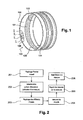
- the figure 2 is a diagram illustrating an example of implementation of the method according to the invention.
- the closed surface chosen is determined essentially according to the blade fragments likely to impact the inner face 104 of the housing 100 when they break.
- a tool is used to delimit the inspection surface.
- a mask to delimit the inspection surface; a mask being simply a material element, for example of cardboard, or of plastic material, in which an opening has been formed which constitutes the shape and dimensions of the mask, and consequently the shape and dimensions of the inspection surface.
- the inspection surface is delimited using a computer that manages the movement of probes in the inspection surface stored by the computer.
- the inspection surface advantageously has a shape and / or dimensions that are variable depending on the area considered.
- a rectangular opening mask of dimension 20 millimeters in width and 71 millimeters in length is chosen for the upstream zone, and for the downstream zone a mask is used.
- the use of the charts by a controller is as follows: once he has determined the inspection surface, he refers, for the first impact I1 of the inspection surface, to the x-axis at which it reports the value I1 (X) of depth measured, 0.8 millimeters in the example illustrated in FIG. figure 3 . He then searches among the curves of the abacus, what is the curve corresponding to the length measured for the impact considered. In the example shown, it is considered that the length of the first impact I1 is 3 millimeters. He then projects the abscissa I1 (X) on the curve considered to obtain a point P1 of the abacus.
- the value of the ordinate I1 (Y) of the point P1 we thus obtain the value of the rate of harmfulness for the first point considered. In the example shown, this value is 40 percent.
- the operation is repeated for all the points of impact identified in the inspection zone during step 203. By summing up the different values of the level of harmfulness obtained for each of the points of impact to be considered, it is obtains the total harmfulness value for the inspection surface considered. If this value is greater than one hundred percent, it is considered that the housing 100 can not be used as is.
Landscapes
- Engineering & Computer Science (AREA)
- General Physics & Mathematics (AREA)
- Physics & Mathematics (AREA)
- Mechanical Engineering (AREA)
- Analytical Chemistry (AREA)
- General Engineering & Computer Science (AREA)
- Life Sciences & Earth Sciences (AREA)
- Chemical & Material Sciences (AREA)
- Health & Medical Sciences (AREA)
- Biochemistry (AREA)
- General Health & Medical Sciences (AREA)
- Immunology (AREA)
- Pathology (AREA)
- Aviation & Aerospace Engineering (AREA)
- Investigating Strength Of Materials By Application Of Mechanical Stress (AREA)
- Structures Of Non-Positive Displacement Pumps (AREA)
- Testing Of Engines (AREA)
- Electrophonic Musical Instruments (AREA)
Description
La présente invention concerne un procédé d'inspection d'impacts observés dans des carters de soufflante de moteurs d'aéronefs.The present invention relates to an impact inspection method observed in aircraft engine fan casings.
Le domaine de l'invention est, d'une façon générale, celui des moteurs d'aéronefs, et plus particulièrement de la surveillance de l'état de ces moteurs au fil du temps. Dans la présente invention, on s'intéresse plus précisément aux carters de soufflante ; on rappelle que dans un tel contexte, une soufflante est d'une manière générale une hélice multiple carénée, qui peut être montée à l'avant ou bien à l'arrière des réacteurs, et dont la fonction est de contribuer à l'augmentation de la poussée générée par le réacteur, en accélérant la grande masse d'air qui la traverse avant l'éjection de celle-ci dans l'atmosphère.The field of the invention is, in general, that of aircraft engines, and more particularly the monitoring of the state of these engines over time. In the present invention, the focus is more specifically on fan casings; it is recalled that in such a context, a fan is generally a ducted multiple propeller, which can be mounted at the front or at the rear of the reactors, and whose function is to contribute to the increase of the thrust generated by the reactor, by accelerating the large mass of air that passes through before the ejection thereof into the atmosphere.
Sur certains moteurs d'aéronefs, les carters de soufflante, et notamment les carters dépourvus de panneaux acoustiques, sont soumis en permanence à des impacts de corps étrangers de taille très variable ; de tels corps sont par exemple du sable, des grêlons, des cailloux, des oiseaux... De tels impacts provoquent une diminution locale de l'épaisseur du carter, ce qui risque d'affecter la capacité de rétention de celui-ci.On certain aircraft engines, the fan casings, and in particular the casings devoid of acoustic panels, are subjected permanently to foreign body impacts of very variable size; such bodies are for example sand, hailstones, pebbles, birds ... Such impacts cause a local decrease in the thickness of the casing, which may affect the retention capacity of the latter.
Ces défauts sont le plus souvent constatés sous l'aile de l'aéronef, lors d'inspections avant décollage, ou lors de visites régulières avec dépose moteur en atelier de maintenance.These defects are most often found under the wing of the aircraft, during inspections before take-off, or during regular inspections with engine removal in the maintenance workshop.
Les carters de soufflante peuvent être réalisés en différents matériaux, par exemple en acier, en composite. Ils sont souvent réalisés en aluminium Des réparations des défauts créés par les impacts mentionnés ont été envisagées par des méthodes de soudure ; mais les procédés classiques par soudure, connus sous l'acronyme TIG, ont été envisagées pour recharger ces impacts mais les procédés classiques (TIG) ne donnent pas de résultats satisfaisants, notamment sur les carters en aluminium. De telles réparations n'étant pas applicables, on a été amené, lorsque les impacts étaient de dimension importantes, à remplacer le carter complet, ou au démontage du moteur.The fan casings can be made of different materials, for example steel, composite. They are often made of aluminum Repair of the defects created by the impacts mentioned were considered by welding methods; but the conventional methods by welding, known under the acronym TIG, were considered to reload these impacts but conventional processes (TIG) do not give results satisfactory, especially on aluminum housings. Such repairs not being applicable, it was brought, when the impacts were of significant size, to replace the complete housing, or the disassembly of the engine.
Une alternative au remplacement complet du carter réside dans l'obtention d'une validation technique qui se traduit par une dérogation administrative, dite CDR, pour pouvoir continuer à utiliser les carters impactés, éventuellement après avoir réalisé de légères retouches sur les défauts observés. Cependant, avec le vieillissement de la flotte et le nombre croissant de moteurs en activité, ces défauts récurrents amènent à des demandes de validation technique de plus en plus nombreuses, et des retards induits sur la remise en service des pièces faisant l'objet des défauts observés.An alternative to the complete replacement of the housing is to obtain a technical validation that results in an administrative derogation, called CDR, to continue to use the impacted housings, possibly after making minor alterations to the defects observed. However, with the aging of the fleet and the increasing number of active engines, these recurring defects lead to more and more numerous requests for technical validation, and delays in the return to service of parts subject to defects. observed.
En conséquence, afin d'accélérer le traitement de ce type de défauts, des critères d'acceptabilité ont été introduits dans la documentation technique. Il existe ainsi désormais des critères d'acceptation des défauts évoqués qui permettent à un contrôleur de statuer rapidement sur la nocivité des défauts sans nécessairement requérir une dérogation. Ces critères d'acceptation ont été établis sur la base des constats sur différents carters et de lois empiriques permettant de statuer sur la capacité de rétention du carter en fonction de son épaisseur résiduelle.Consequently, in order to speed up the treatment of this type of defects, acceptability criteria have been introduced in the technical documentation. Henceforth, there are now criteria for acceptance of the evoked faults that allow a controller to quickly decide on the harmfulness of faults without necessarily requiring a derogation. These acceptance criteria were established on the basis of observations on different casings and empirical laws making it possible to decide on the capacity of retention of the casing as a function of its residual thickness.
Ces critères d'acceptation se présentent sous la forme de trinômes de dimensions caractérisant les défauts admissibles ; une première valeur de ce trinôme est relative à une profondeur maximale admissible, une deuxième valeur est relative à une longueur maximale admissible, et une troisième valeur est relative à une distance minimale à observer entre deux défauts, notamment deux défauts liés à un impact. Ainsi, par exemple, pour une zone amont d'un carter, si un contrôleur détecte un impact d'une profondeur de 0,1524 mm (millimètres), il a connaissance du fait, par l'existence d'un trinôme associé à cette profondeur, que le défaut considéré ne doit pas présenter une longueur supérieure à 25,4 mm, et qu'aucun autre défaut ne doit être présent à une distance inférieure à 3,048 mm.These acceptance criteria are in the form of trinomials of dimensions characterizing the allowable defects; a first value of this trinomial is relative to a maximum allowable depth, a second value relates to a maximum allowable length, and a third value relates to a minimum distance to be observed between two defects, in particular two defects related to an impact. Thus, for example, for an upstream zone of a crankcase, if a controller detects an impact of a depth of 0.1524 mm (millimeters), it is aware of the fact, by the existence of a trinomial associated with this depth, that the defect under consideration should not have a length greater than 25.4 mm, and no other defects must be present at a distance of less than 3,048 mm.
Malheureusement, ces critères d'acceptation ne permettent d'accepter qu'un nombre limité de défauts, du fait de la nécessité de disposer de valeurs de référence comparables, et n'empêchent donc pas l'augmentation du nombre de validations demandées ; il faudrait, pour remédier à ce problème, accepter d'introduire constamment de nouveaux critères d'acceptation à chaque nouveau défaut constaté, ce qui ne constitue pas une solution viable à long terme. De plus, compte-tenu du nombre de trinômes de valeurs déjà présents disponibles, cette méthode d'inspection peut s'avérer assez lourde et complexe pour les contrôleurs.Unfortunately, these acceptance criteria make it possible to accept only a limited number of defects, because of the need to have comparable reference values, and thus do not prevent the increase in the number of validations requested; In order to remedy this problem, it would be necessary to agree to constantly introduce new acceptance criteria for each new defect found, which is not a viable long-term solution. Moreover, given the number of trinomials of values already present available, this inspection method can be rather cumbersome and complex for the controllers.
Le document
L'objet de l'invention offre une solution aux problèmes qui viennent d'être exposés en proposant un procédé d'inspection simplifié, rendant la tâche plus aisée pour les contrôleurs ; l'invention vise à évaluer de manière simple la nocivité des impacts observés afin d'accélérer le traitement de ces défauts. Pour ce faire, la présente invention propose l'utilisation d'outils d'inspection simples, qui ne nécessitent pas de formation particulière pour leur utilisation, qui permettent essentiellement de s'affranchir de déterminer les distances entre les différents impacts tout en permettant de statuer rapidement sur l'acceptation ou non de ces défauts vis-à-vis de la capacité de rétention du carter de soufflante.The object of the invention offers a solution to the problems that have just been exposed by proposing a simplified inspection method, making the task easier for the controllers; the invention aims to evaluate in a simple manner the harmfulness of the impacts observed in order to accelerate the treatment of these defects. To do this, the present invention proposes the use of simple inspection tools, which do not require any particular training for their use, which essentially make it possible to dispense with determining the distances between the different impacts while making it possible to decide quickly on the acceptance or not of these defects vis-à-vis the retention capacity of the fan case.
L'invention concerne donc essentiellement un procédé d'inspection d'impacts présents sur une face interne de carter de soufflante, ledit procédé étant caractérisé en ce qu'il comporte les différentes étapes consistant à :
- repérer un premier impact présent sur la face interne du carter de soufflante ;
- délimiter une surface d'inspection comportant ledit premier impact ;
- repérer les différents impacts présents dans la surface d'inspection délimitée, lesdits différents impacts repérés formant un ensemble d'impacts à considérer ;
- mesurer, pour chaque impact à considérer, la profondeur et la longueur dudit impact;
- pour chaque impact à considérer, déterminer une valeur de taux de nocivité, au moyen d'au moins un abaque mettant en relation la profondeur et la longueur de chaque impact à considérer avec un taux de nocivité ;
- déterminer, pour la surface d'inspection comportant le premier impact, une valeur de taux de nocivité total en additionnant le taux de nocivité déterminé pour chaque impact à considérer.
- locate a first impact present on the inner face of the fan casing;
- defining an inspection surface including said first impact;
- identify the different impacts present in the defined inspection area, said various identified impacts forming a set of impacts to be considered;
- measure, for each impact to be considered, the depth and the length of said impact;
- for each impact to be considered, determine a value of harmfulness rate, by means of at least one abacus relating the depth and the length of each impact to be considered with a rate of harmfulness;
- determining, for the inspection surface comprising the first impact, a total harmfulness value by adding the harmfulness rate determined for each impact to be considered.
Outre les caractéristiques principales qui viennent d'être mentionnées dans le paragraphe précédent, le procédé selon l'invention peut présenter une ou plusieurs caractéristiques complémentaires parmi les suivantes, considérées individuellement ou selon toutes les combinaisons techniquement possibles :
- l'étape consistant à délimiter une surface d'inspection contenant le premier impact est réalisée au moyen d'un masque.
- le masque est de forme rectangulaire.
- les dimensions du masque dépendent de la localisation de la surface d'inspection, un premier masque de premières dimensions étant utilisé pour une zone amont du carter, et/ou un deuxième masque de deuxièmes dimensions étant utilisé pour une zone abradable du carter, et/ou un troisième masque de troisièmes dimensions pouvant être utilisé pour une zone aval du carter.
- le premier masque est de forme rectangulaire, de longueur 71 millimètres plus ou moins dix pour cent, avantageusement 71 millimètres, et de
largeur 20 millimètres plus ou moins dix pour cent, avantageusement 20 millimètres, et/ou le troisième masque est de forme carrée, de côté 250 millimètres plus ou moins dix pour cent, avantageusement 250 millimètres. - le masque est de forme rectangulaire ayant les caractéristiques suivantes :
- un premier côté du masque a une dimension comprise entre le cinquième de la corde des aubes du carter et la longueur de corde desdites aubes
- un deuxième côté du masque a une dimension comprise entre le cinquième de la corde desdites aubes et la hauteur de la pale de ladite aube.
- the step of defining an inspection surface containing the first impact is performed by means of a mask.
- the mask is rectangular in shape.
- the dimensions of the mask depend on the location of the inspection surface, a first mask of first dimensions being used for an upstream zone of the casing, and / or a second mask of second dimensions being used for an abradable zone of the casing, and / or a third mask of third dimensions that can be used for a downstream zone of the housing.
- the first mask is of rectangular shape, of length 71 millimeters plus or minus ten percent, advantageously 71 millimeters, and
width 20 millimeters plus or minus ten percent, advantageously 20 millimeters, and / or the third mask is square, side 250 millimeters plus or minus ten percent, advantageously 250 millimeters. - the mask is rectangular in shape having the following characteristics:
- a first side of the mask has a dimension between one-fifth of the blade of the crankcase blades and the length of rope of said blades
- a second side of the mask has a dimension between one-fifth of the string of said blades and the height of the blade of said blade.
Ces dimensions sont déterminées empiriquement en fonction de la zone considérée du carter et à partir du schéma de fragmentation des aubes qui détermine la forme et les dimensions des zones d'impact des fragments. Le schéma de fragmentation des aubes est propre à chaque technologie d'aube (aubes à talon, aubes à nageoires, aubes large corde,...).
- chaque masque est associé à un abaque spécifique utilisé pour déterminer un taux de nocivité à partir des informations de profondeur et de longueur de chaque impact à considérer.
- l'étape consistant à délimiter une surface d'inspection contenant le premier impact est réalisée au moyen de palpeurs et d'un calculateur associé.
- chaque abaque met en relation une valeur mesurée de la profondeur de l'impact à considérer et une plage de valeurs comprenant une valeur mesurée de la longueur de l'impact à considérer avec un taux de nocivité.
- la plage de valeurs comprenant la valeur mesurée de la longueur de l'impact à considérer a une amplitude de 5 millimètres au moins pour des impacts présentant une longueur inférieure à 30 millimètres.
- le procédé comporte l'étape supplémentaire consistant à, avant l'étape de mesure, exclure de l'ensemble d'impacts à considérer les impacts ayant une profondeur inférieure à 0,1 millimètre.
- each mask is associated with a specific abacus used to determine a rate of harm from the depth and length information of each impact to be considered.
- the step of defining an inspection surface containing the first impact is performed by means of probes and an associated computer.
- each abacus relates a measured value of the depth of the impact to be considered and a range of values including a measured value of the length of the impact to be considered with a harmfulness rate.
- the range of values including the measured value of the length of the impact to be considered has an amplitude of at least 5 millimeters for impacts with a length of less than 30 millimeters.
- the method comprises the additional step of, before the measuring step, excluding from the set of impacts to consider impacts having a depth less than 0.1 millimeter.
L'invention et ses différentes applications seront mieux comprises à la lecture de la description qui suit et à l'examen des figures qui l'accompagnent.The invention and its various applications will be better understood by reading the following description and examining the figures that accompany it.
Les figures ne sont présentées qu'à titre indicatif et nullement limitatif de l'invention. Les figures montrent :
- à la
figure 1 , une représentation schématique d'un exemple de carter de soufflante sur lequel peut être mis en oeuvre le procédé selon l'invention ; - à la
figure 2 , un diagramme illustrant un exemple de mise en oeuvre du procédé selon l'invention ; - à la
figure 3 , un premier exemple d'abaque susceptible d'être utilisé dans un exemple de mise en oeuvre du procédé selon l'invention ; - à la
figure 4 , un deuxième exemple d'abaque susceptible d'être utilisé dans un exemple de mise en oeuvre du procédé selon l'invention.
- to the
figure 1 a schematic representation of an example of a fan casing on which the method according to the invention can be implemented; - to the
figure 2 a diagram illustrating an example of implementation of the method according to the invention; - to the
figure 3 a first example of an abacus that can be used in an exemplary implementation of the method according to the invention; - to the
figure 4 , a second example of an abacus that can be used in an exemplary implementation of the method according to the invention.
Sauf précision contraire, un même élément apparaissant sur des figures différentes présente une référence unique.Unless otherwise specified, the same element appearing in different figures has a unique reference.
Sur la
Le carter 100 comporte une face interne 104, dont une partie centrale 101 présente une zone abradable 105. Dans la pratique, la zone abradable 105 est disposée en regard des aubes; sa fonction est de limiter la détérioration du carter lorsque les aubes frottent légèrement sur la face interne 104.The
De part et d'autre de la zone abradable on trouve respectivement une zone amont 102, qui est la première zone rencontrée par l'air entrant dans le carter 100, et une zone aval 103, qui est la zone traversée par l'air une fois que celui-ci a été accéléré par les aubes en mouvement.On either side of the abradable zone there is respectively an
La
Sur cette figure, on a représenté les étapes successives à observer pour l'exemple de mise en oeuvre considéré du procédé selon l'invention. On distingue ainsi, successivement :
- une première étape 201, dite étape de repérage d'un premier impact I1 (visible sur la
figure 1 ), sur laface interne 104 du carter. Ce repérage est avantageusement réalisé de manière visuelle par un contrôleur. Dans un mode perfectionné du procédé selon l'invention, on peut utiliser des capteurs de type palpeur pour repérer le premier impact ; mais la solution visuelle, du fait de sa simplicité de mise en oeuvre, est avantageuse. Avantageusement, le premier impact n'est retenu que si il présente une profondeur supérieure à 0,1 millimètre ; - une deuxième étape 202, dite étape de détermination d'une surface d'inspection 106 (visible sur la
figure 1 ), dans laquelle on détermine une surface fermée de laface interne 104, surface fermée dans laquelle se trouve le premier impact, et sur laquelle le contrôleur va mesurer un taux de nocivité total. Le taux de nocivité est la grandeur qui va permettre de déterminer si l'ensemble des impacts détectés dans la zone sensible est considéré comme ayant trop détérioré le carter considéré pour que celui-ci puisse continuer à être utilisé, c'est-à-dire que sa capacité de rétention, au niveau de la surface d'inspection, n'a pas réduit la capacité de rétention ducarter 100 de manière rédhibitoire.
- a
first step 201, said step of locating a first impact I1 (visible on thefigure 1 ), on theinner face 104 of the housing. This identification is advantageously performed visually by a controller. In an improved mode of the method according to the invention, it is possible to use sensors probing type to identify the first impact; but the visual solution, because of its simplicity of implementation, is advantageous. Advantageously, the first impact is retained only if it has a depth greater than 0.1 millimeter; - a
second step 202, said step of determining an inspection surface 106 (visible on thefigure 1 ), in which a closed surface of theinner face 104 is determined, the closed surface in which the first impact is located, and on which the controller will measure a total level of harmfulness. The degree of harmfulness is the quantity that will make it possible to determine whether all the impacts detected in the sensitive zone are considered to have too deteriorated the casing considered so that it can continue to be used, that is to say its retention capacity at the inspection surface has not reduced the retention capacity of thecasing 100 in a crippling manner.
La surface fermée choisie est déterminée essentiellement en fonction des fragments d'aube susceptible d'impacter la face interne 104 du carter 100 lorsque ceux-ci se brisent.The closed surface chosen is determined essentially according to the blade fragments likely to impact the
Un outil est utilisé pour délimiter la surface d'inspection. Avantageusement, dans l'invention, on propose l'utilisation d'un masque pour délimiter la surface d'inspection ; un masque étant simplement un élément matériel, par exemple en carton, ou en matière plastique, dans lequel on a ménagé une ouverture qui constitue la forme et les dimensions du masque, et en conséquence la frome et les dimensions de la surface d'inspection. Dans des exemples de mise en oeuvre plus élaborés, mais moins simples de mise en oeuvre, la surface d'inspection est délimitée en utilisant un calculateur qui gère le déplacement de palpeurs dans la surface d'inspection mémorisée par le calculateur.A tool is used to delimit the inspection surface. Advantageously, in the invention, it is proposed to use a mask to delimit the inspection surface; a mask being simply a material element, for example of cardboard, or of plastic material, in which an opening has been formed which constitutes the shape and dimensions of the mask, and consequently the shape and dimensions of the inspection surface. In more elaborate, but less simple implementation examples of implementation, the inspection surface is delimited using a computer that manages the movement of probes in the inspection surface stored by the computer.
Sous perte d'aube, c'est-à-dire lorsqu'une aube se détache, le carter est sollicité différemment selon les zones étudiées. En effet, lors d'une perte d'aube, la pale se fragmente en plusieurs morceaux de tailles et de masses différentes qui vont ensuite impacter le carter avec des vitesses variables suivant la zone (zone aval, zone amont, zone abradable). Ainsi, la surface d'inspection présente avantageusement une forme et/ou des dimensions qui sont variables en fonction de la zone considérée.Under dawn loss, that is to say when a blade is detached, the housing is solicited differently depending on the areas studied. Indeed, during a dawn loss, the blade is broken up into several pieces of different sizes and masses which will then impact the casing with variable speeds. following the zone (downstream zone, upstream zone, abradable zone). Thus, the inspection surface advantageously has a shape and / or dimensions that are variable depending on the area considered.
Dans des modes de mise en oeuvre avantageux de l'invention sur un moteur CFM56-7B, on choisit pour la zone amont un masque d'ouverture rectangulaire de dimension 20 millimètres de largeur et 71 millimètres de longueur, et pour la zone aval un masque de forme carrée de côté 250 millimètres.In advantageous embodiments of the invention on a CFM56-7B engine, a rectangular opening mask of
Le contrôleur recherche, grâce au masque, une surface critique. Cette surface critique correspond à celle comportant un maximum d'impacts nocifs pouvant rentrer dans la fenêtre. Par impact nocif, on désigne typiquement les impacts dont la profondeur est supérieure à 0,1 millimètre. L'inspecteur sera ainsi amené à répéter les opérations d'inspection pour toutes les combinaisons d'impacts possibles.
- une troisième étape 203 au cours de laquelle le contrôleur repère différents impacts Ii (visibles sur la
figure 1 ) présents dans lasurface d'inspection 106. - une quatrième étape 204 au cours de laquelle le contrôleur mesure la profondeur et la longueur de chaque impact, avantageusement de chaque impact nocif, de la surface d'inspection délimitée par le masque.
- une cinquième étape 205 dans laquelle le contrôleur reporte les informations de mesure sur un abaque approprié. Avantageusement, on définit, dans l'invention, un abaque par zone du carter (zone amont, zone aval, zone abradable) est proposé. La
figure 3 montre un exemple avantageux d'abaque 300 utilisé pour les contrôles dans la zone amont du carter de soufflante 100, avec des valeurs fonctionnelles, et lafigure 4 montre un exemple avantageux d'abaque 400 utilisé pour les contrôles dans la zone aval du carter de soufflante 100, avec des valeurs fonctionnelles. Ainsi, avantageusement, dans le procédé d'inspection selon l'invention, on associe de manière bijective un masque et un abaque pour réaliser les contrôles.
- a
third step 203 during which the controller identifies different impacts Ii (visible on thefigure 1 ) present in theinspection surface 106. - a
fourth step 204 during which the controller measures the depth and length of each impact, advantageously of each harmful impact, of the inspection surface delimited by the mask. - a
fifth step 205 in which the controller reports the measurement information on a suitable chart. Advantageously, it is defined in the invention, an abacus by crankcase zone (upstream zone, downstream zone, abradable zone) is proposed. Thefigure 3 shows an advantageous example ofabacus 300 used for the controls in the upstream zone of thefan casing 100, with functional values, and thefigure 4 shows an advantageous example ofabacus 400 used for the controls in the downstream zone of thefan casing 100, with functional values. Thus, advantageously, in the inspection method according to the invention, a mask and an abacus are associated in a bijective manner to carry out the checks.
Les abaques proposés selon l'invention sont organisés de la manière suivante :
- en abscisse, on trouve les valeurs mesurées des profondeurs des impacts ;
- en ordonnée, on trouve un pourcentage de nocivité de chaque impact considéré dans la surface d'inspection ;
- différentes courbes, des portions de droite dans les exemples représentés, assurent la mise en relation entre une profondeur d'impact et un pourcentage de nocivité associé à cet impact. Les courbes sont élaborées pour chaque longueur d'impact observé. Avantageusement, afin de limiter le nombre de courbes, chaque courbe de l'abaque est représentative d'une plage de valeurs de longueur d'impact mesuré.
- on the abscissa, we find the measured values of the depths of the impacts;
- on the ordinate, we find a percentage of harmfulness of each impact considered in the inspection surface;
- various curves, right-hand portions in the examples shown, ensure the connection between an impact depth and a percentage of harmfulness associated with this impact. Curves are developed for each impact length observed. Advantageously, in order to limit the number of curves, each curve of the chart is representative of a range of measured impact length values.
Ces abaques sont conçus à partir d'une population représentative, typiquement quatre vingt dix pour cent des défauts constatés, retenue dans une distribution statistique des défauts en fonction de leurs longueurs. On cherche à couvrir un maximum de couples (profondeur ; longueur) de cette population représentative à l'aide d'un nombre minimal de courbes. Ces courbes sont ensuite optimisées par prise en compte de retour d'expérience des inspecteurs et de phénomènes tels que l'érosion.
- une sixième étape 206 dans laquelle le contrôleur exploite les abaques pour déterminer une valeur de nocivité totale pour la surface d'inspection à considérer.
- a
sixth step 206 in which the controller operates the charts to determine a total value of harmfulness for the inspection surface to be considered.
L'utilisation des abaques par un contrôleur est la suivante : une fois qu'il a déterminé la surface d'inspection, il se réfère, pour le premier impact I1 de la surface d'inspection, à l'axe des abscisses au niveau duquel il reporte la valeur I1(X) de profondeur mesurée, 0,8 millimètre dans l'exemple illustré à la
On remarquera que les abaques des
La méthode d'inspection selon l'invention fait apparaître les avantages majeurs suivants :
- Nombre important de défauts couverts :
- Le nombre de défauts couverts par cette inspection est considérablement augmenté par rapport à l'utilisation des critères actuels.
- Diminution du temps d'inspection :
- Au lieu de relever trois paramètres par impacts (longueur, profondeur et distance inter-défaut) le contrôleur n'en relève plus que deux ; le troisième paramètre étant remplacé par l'utilisation du masque ou d'un moyen équivalent. De plus, la prise en compte des seules profondeurs d'impact supérieures à 0.1 mm diminue le nombre d'impacts contrôlés au moins par deux par rapport aux méthodes utilisées dans l'état de la technique.
- Souplesse du moyen et facilité de mise en oeuvre:
- La simplicité et le faible encombrement des outils masque-abaque rend possible son déploiement dans tous les ateliers de maintenance et permet également les inspections sous l'aile, ce qui est un avantage non négligeable.
- Significant number of defects covered:
- The number of defects covered by this inspection is considerably increased compared to the use of the current criteria.
- Decrease inspection time:
- Instead of taking three parameters per impact (length, depth and inter-fault distance), the controller only finds two more; the third parameter being replaced by the use of the mask or equivalent means. In addition, taking into account only the impact depths greater than 0.1 mm reduces the number of impacts checked at least by two compared to the methods used in the state of the art.
- Flexibility of the means and ease of implementation:
- The simplicity and small size of the mask-abacus tools makes it possible to deploy in all maintenance workshops and also allows inspections under the wing, which is a significant advantage.
Dans un mode de mise en oeuvre particulier de l'invention, on prévoit l'utilisation de moyens de contrôle automatique utilisant un moyen de mesure (type palpeur) couplé à un logiciel de calcul de la nocivité des défauts (programmé à l'aide des abaques). Si ce mode de mise en oeuvre est plus coûteux et plus encombrant à mettre en oeuvre que le mode de mise en oeuvre utilisant les masques, il demeure une possibilité de mise en oeuvre du procédé selon l'invention.In a particular embodiment of the invention, provision is made for the use of automatic control means using measuring means. (probe type) coupled to a software for calculating the harmfulness of defects (programmed using charts). If this mode of implementation is more expensive and more cumbersome to implement than the embodiment using the masks, there remains a possibility of implementing the method according to the invention.
Claims (10)
- A method for inspecting impacts (Ii) present on an internal face (104) of a fan casing (100), said method being characterised in that it includes the different steps of:- spotting (201) a first impact (I1) present in the internal face (104) of the fan casing (100);- delimiting (202) an inspection area (106) including said first impact (I1);- spotting (203) the different impacts (Ii) present on the delimited inspection area (106), said different spotted impacts forming a set of impacts to be considered;- measuring (204), for each impact (Ii) to be considered, the depth and length of said impact (Ii);- for each impact (Ii) to be considered, determining (205) a level of harmfulness value, by means of at least one chart (300; 400) relating the depth and length of each impact to be considered to a level of harmfulness;- determining (206), for the inspection area (106) including the first impact (I1), a total level of harmfulness value by adding the level of harmfulness determined for each impact (Ii) to be considered.
- The method according to the preceding claim, characterised in that the step of delimiting (202) the inspection area (106) containing the first impact is performed by means of a mask.
- The method according to the preceding claim, characterised in that the mask is rectangular in shape and has the following characteristics:- a first side of the mask has a dimension between the fifth part of the chord of the casing vanes and the length of the chord of said vanes;- a second side of the mask has a dimension between the fifth part of the chord of said vanes and the height of the blade of said vanes.
- The method according to any of claims 2 and 3, characterised in that the dimensions of the mask depend on the location of the inspection area, a first mask having first dimensions being used for an upstream zone (102) of the casing and/or a second mask having second dimensions being used for an abradable zone (105) of the casing and/or a third mask having third dimensions being used for a downstream zone (103) of the casing.
- The method according to the preceding claim, characterised in that the first mask is rectangular in shape, having a length 71 millimetres within ten per cent, in particular 71 millimetres, and a width 20 millimetres within ten per cent, in particular 20 millimetres, and/or the third mask is square in shape, having a side 250 millimetres within ten per cent, in particular 250 millimetres.
- The method according to the preceding claim, characterised in that each mask is associated with a specific chart used for determining a level of harmfulness from depth and length information of each impact to be considered.
- The method according to claim 1, characterised in that the step of delimiting (202) the inspection area (106) containing the first impact (I1) is performed by means of tracers and an associated calculator.
- The method according to any of the preceding claims, characterised in that each chart (300; 400) relates a measured value of the depth of the impact to be considered and a range of values comprising a measured value of the length of the impact to be considered to a level of harmfulness.
- The method according to the preceding claim, characterised in that the range of values comprising the measured value of the length of the impact to be considered has an amplitude of at least 5 millimetres for impacts having a length lower than 30 millimetres.
- The method according to any of the preceding claims, characterised in that it includes the further step of, prior to the measuring step, excluding from the set of impacts to be considered the impacts having a depth lower than 0.1 millimetres.
Applications Claiming Priority (2)
| Application Number | Priority Date | Filing Date | Title |
|---|---|---|---|
| FR1152492A FR2973110B1 (en) | 2011-03-25 | 2011-03-25 | METHOD FOR INSPECTING IMPACTS OBSERVED IN BLOWER CONTAINERS |
| PCT/FR2012/050542 WO2012131211A1 (en) | 2011-03-25 | 2012-03-15 | Method of inspecting impacts observed in fan casings |
Publications (2)
| Publication Number | Publication Date |
|---|---|
| EP2688707A1 EP2688707A1 (en) | 2014-01-29 |
| EP2688707B1 true EP2688707B1 (en) | 2015-03-11 |
Family
ID=45974408
Family Applications (1)
| Application Number | Title | Priority Date | Filing Date |
|---|---|---|---|
| EP12714785.8A Active EP2688707B1 (en) | 2011-03-25 | 2012-03-15 | Method of inspecting impacts observed in fan casings |
Country Status (9)
| Country | Link |
|---|---|
| US (1) | US9494486B2 (en) |
| EP (1) | EP2688707B1 (en) |
| JP (1) | JP6080174B2 (en) |
| CN (1) | CN103459087B (en) |
| BR (1) | BR112013023457B1 (en) |
| CA (1) | CA2830834C (en) |
| FR (1) | FR2973110B1 (en) |
| RU (1) | RU2603399C2 (en) |
| WO (1) | WO2012131211A1 (en) |
Families Citing this family (8)
| Publication number | Priority date | Publication date | Assignee | Title |
|---|---|---|---|---|
| GB201401111D0 (en) * | 2014-01-23 | 2014-03-12 | Rolls Royce Plc | A method of inspecting the fan track liner of a gas turbine engine |
| CN105099631A (en) * | 2014-04-17 | 2015-11-25 | 北京三星通信技术研究有限公司 | Method and device for processing flexible duplex |
| US10612413B2 (en) * | 2017-03-06 | 2020-04-07 | United Technologies Corporation | Wear indicator for determining wear on a component of a gas turbine engine |
| US10576588B2 (en) | 2017-09-05 | 2020-03-03 | S L Chasse Welding & Fabricating, Inc. | Fabrication layout device and method |
| DE102017221891B4 (en) * | 2017-12-05 | 2020-03-19 | Bayerische Motoren Werke Aktiengesellschaft | Method for determining damage that occurs to the vehicle in an accident between a vehicle and a collision partner |
| FR3087535B1 (en) * | 2018-10-18 | 2020-11-13 | Safran Aircraft Engines | TOOLS AND METHOD FOR ENDOSCOPIC INSPECTION OF A MANIFOLD CASING OF AN AIRCRAFT TURBOMACHINE |
| CN109443735B (en) * | 2018-12-21 | 2024-03-19 | 杭州戬威机电科技有限公司 | Detection device for surface defects of wind driven generator blade |
| USD1002416S1 (en) | 2020-01-14 | 2023-10-24 | Donner Nicholas J | Marker device for use with a CNC layout table |
Family Cites Families (18)
| Publication number | Priority date | Publication date | Assignee | Title |
|---|---|---|---|---|
| SU544208A1 (en) * | 1975-11-27 | 1981-12-15 | Предприятие П/Я М-5906 | Method of restoring turbomachine blade fin |
| SU793742A1 (en) * | 1977-07-05 | 1981-01-07 | Предприятие П/Я Р-6639 | Method of restoring the blades of gas-turbine engines |
| JPS6387289A (en) * | 1986-09-30 | 1988-04-18 | 日産自動車株式会社 | Estimating device for repair cost of car |
| US4950911A (en) * | 1986-12-10 | 1990-08-21 | Process Automation Business, Inc. | Apparatus and method for inspecting sheet material |
| JPH0273473A (en) * | 1988-09-09 | 1990-03-13 | Brother Ind Ltd | Inspecting method |
| US5083867A (en) * | 1988-11-28 | 1992-01-28 | Allegheny Ludlum Corporation | Slab surface contour monitor |
| US6122065A (en) * | 1996-08-12 | 2000-09-19 | Centre De Recherche Industrielle Du Quebec | Apparatus and method for detecting surface defects |
| JPH10160646A (en) * | 1996-12-03 | 1998-06-19 | Toshiba Corp | Method for anticipating fatigue life of structure member |
| US6219930B1 (en) * | 1998-02-27 | 2001-04-24 | Randall M. McPherson | Apparatus and method of use for calculating an estimate of damaged surface repair cost |
| US6779159B2 (en) * | 2001-06-08 | 2004-08-17 | Sumitomo Mitsubishi Silicon Corporation | Defect inspection method and defect inspection apparatus |
| US6985220B1 (en) * | 2003-08-20 | 2006-01-10 | Kla-Tencor Technologies Corporation | Interactive threshold tuning |
| US7187436B2 (en) * | 2004-03-30 | 2007-03-06 | General Electric Company | Multi-resolution inspection system and method of operating same |
| US7018168B2 (en) * | 2004-04-08 | 2006-03-28 | General Electric Company | Method and apparatus for fabricating gas turbine engines |
| JP2005339249A (en) * | 2004-05-27 | 2005-12-08 | Toshiba Corp | Repair plan support method and apparatus for plant equipment member |
| FR2901246B1 (en) * | 2006-05-19 | 2008-06-20 | Airbus France Sas | METHOD FOR REPAIRING A DAMAGED ZONE OF AN AIRCRAFT FUSELAGE |
| CN100474548C (en) * | 2006-07-27 | 2009-04-01 | 上海宏力半导体制造有限公司 | Device for detecting metal etching defect |
| JP4875639B2 (en) * | 2008-01-25 | 2012-02-15 | 三菱重工業株式会社 | Life evaluation method |
| JP5322841B2 (en) * | 2009-08-18 | 2013-10-23 | 株式会社東芝 | Mask defect shape measurement method and mask quality determination method |
-
2011
- 2011-03-25 FR FR1152492A patent/FR2973110B1/en not_active Expired - Fee Related
-
2012
- 2012-03-15 RU RU2013147623/02A patent/RU2603399C2/en active
- 2012-03-15 BR BR112013023457-1A patent/BR112013023457B1/en active IP Right Grant
- 2012-03-15 EP EP12714785.8A patent/EP2688707B1/en active Active
- 2012-03-15 JP JP2014500441A patent/JP6080174B2/en active Active
- 2012-03-15 CN CN201280015080.7A patent/CN103459087B/en active Active
- 2012-03-15 WO PCT/FR2012/050542 patent/WO2012131211A1/en active Application Filing
- 2012-03-15 CA CA2830834A patent/CA2830834C/en active Active
- 2012-03-15 US US14/007,269 patent/US9494486B2/en active Active
Also Published As
| Publication number | Publication date |
|---|---|
| FR2973110B1 (en) | 2013-04-26 |
| BR112013023457B1 (en) | 2021-07-13 |
| EP2688707A1 (en) | 2014-01-29 |
| JP6080174B2 (en) | 2017-02-15 |
| RU2603399C2 (en) | 2016-11-27 |
| CN103459087B (en) | 2016-12-07 |
| US9494486B2 (en) | 2016-11-15 |
| FR2973110A1 (en) | 2012-09-28 |
| CA2830834A1 (en) | 2012-10-04 |
| JP2014514485A (en) | 2014-06-19 |
| BR112013023457A2 (en) | 2016-12-06 |
| CA2830834C (en) | 2019-07-02 |
| CN103459087A (en) | 2013-12-18 |
| RU2013147623A (en) | 2015-04-27 |
| WO2012131211A1 (en) | 2012-10-04 |
| US20140020485A1 (en) | 2014-01-23 |
Similar Documents
| Publication | Publication Date | Title |
|---|---|---|
| EP2688707B1 (en) | Method of inspecting impacts observed in fan casings | |
| EP1749969B1 (en) | Inspection of the blades of a turbine | |
| FR2949220A1 (en) | METHOD AND SYSTEM FOR DETECTING THE INGESTION OF AN OBJECT BY AN AIRCRAFT TURBOJUSTER DURING A MISSION | |
| EP3318940B1 (en) | Drilling method comprising a measurement of drag, and corresponding piercing device | |
| FR3046809B1 (en) | METHOD FOR DETERMINING THE STATE OF USE OF A DRILL, AND CORRESPONDING DEVICE | |
| WO2020089555A1 (en) | Device and method for monitoring the lifetime of a hydraulic apparatus of an aircraft | |
| WO2014009634A1 (en) | Method for detecting deterioration in a turbomachine by monitoring the performance of said turbomachine | |
| CA2332470C (en) | Process for the early detection of aerodynamic instabilities in a turbomachine compressor | |
| EP3303850B1 (en) | Method for manufacturing a turbomachine fan having a reduced noise level at multiple rotational frequencies of said turbomachine | |
| EP2130031A1 (en) | Automated visual checking device | |
| FR3080184A1 (en) | METHOD FOR MEASURING THE CORROSION OF A WORKPIECE AND APPLICATION TO THE CONTROL OF THE MECHANICAL RESISTANCE OF A CORRODEE PIECE | |
| EP3588398B1 (en) | Test bench with maintenance system and method for maintenance of such a test bench | |
| FR3091548A1 (en) | Abradable element of a turbomachine provided with visual wear indicators | |
| FR3050772A1 (en) | MANAGEMENT OF A WATER SUPPLY PUMPING OF A CIRCUIT OF AN ELECTRIC PRODUCTION PLANT | |
| Ataya et al. | An investigation of damages in low power wind turbine blades | |
| WO2018154236A1 (en) | Process for inspecting a casing by colorimetry | |
| FR3123474A1 (en) | Method for classifying a fracture mode visible on an image of a fracture surface of a bonded assembly | |
| FR3073045B1 (en) | METHOD FOR BALANCING A SET OF AUBES | |
| FR3003953A1 (en) | ULTRASONIC FAULT DETECTION SYSTEM ON AN AIRCRAFT ENGINE ROTATING ELEMENT | |
| FR3051559A1 (en) | METHOD FOR OPTIMIZING THE DETECTION OF MARINE AND RADAR TARGETS USING SUCH A METHOD | |
| FR3127285A1 (en) | Turbomachine test method for monitoring fan flutter | |
| FR3140291A1 (en) | METHOD FOR MULTI-DRILLING BY ELECTROEROSION OF HOLES IN A WALL OF A ROOM | |
| FR3141358A1 (en) | METHOD FOR MANUFACTURING A BROOCH ELEMENT FOR BROOCHING A PART | |
| FR3121431A1 (en) | Method for predicting the wear of a mechanical part, method for determining the operational risk associated with an aircraft or a fleet of aircraft | |
| FR3132453A1 (en) | Method for predicting an optimal material exclusion diameter for the angle breaking of a burr |
Legal Events
| Date | Code | Title | Description |
|---|---|---|---|
| PUAI | Public reference made under article 153(3) epc to a published international application that has entered the european phase |
Free format text: ORIGINAL CODE: 0009012 |
|
| 17P | Request for examination filed |
Effective date: 20130910 |
|
| AK | Designated contracting states |
Kind code of ref document: A1 Designated state(s): AL AT BE BG CH CY CZ DE DK EE ES FI FR GB GR HR HU IE IS IT LI LT LU LV MC MK MT NL NO PL PT RO RS SE SI SK SM TR |
|
| DAX | Request for extension of the european patent (deleted) | ||
| GRAP | Despatch of communication of intention to grant a patent |
Free format text: ORIGINAL CODE: EPIDOSNIGR1 |
|
| INTG | Intention to grant announced |
Effective date: 20140925 |
|
| GRAS | Grant fee paid |
Free format text: ORIGINAL CODE: EPIDOSNIGR3 |
|
| GRAA | (expected) grant |
Free format text: ORIGINAL CODE: 0009210 |
|
| AK | Designated contracting states |
Kind code of ref document: B1 Designated state(s): AL AT BE BG CH CY CZ DE DK EE ES FI FR GB GR HR HU IE IS IT LI LT LU LV MC MK MT NL NO PL PT RO RS SE SI SK SM TR |
|
| REG | Reference to a national code |
Ref country code: GB Ref legal event code: FG4D Free format text: NOT ENGLISH |
|
| REG | Reference to a national code |
Ref country code: CH Ref legal event code: EP |
|
| REG | Reference to a national code |
Ref country code: IE Ref legal event code: FG4D Free format text: LANGUAGE OF EP DOCUMENT: FRENCH |
|
| REG | Reference to a national code |
Ref country code: AT Ref legal event code: REF Ref document number: 715046 Country of ref document: AT Kind code of ref document: T Effective date: 20150415 |
|
| REG | Reference to a national code |
Ref country code: DE Ref legal event code: R096 Ref document number: 602012005853 Country of ref document: DE Effective date: 20150423 |
|
| REG | Reference to a national code |
Ref country code: SE Ref legal event code: TRGR |
|
| REG | Reference to a national code |
Ref country code: NL Ref legal event code: VDEP Effective date: 20150311 |
|
| REG | Reference to a national code |
Ref country code: NL Ref legal event code: VDEP Effective date: 20150311 |
|
| PG25 | Lapsed in a contracting state [announced via postgrant information from national office to epo] |
Ref country code: ES Free format text: LAPSE BECAUSE OF FAILURE TO SUBMIT A TRANSLATION OF THE DESCRIPTION OR TO PAY THE FEE WITHIN THE PRESCRIBED TIME-LIMIT Effective date: 20150311 Ref country code: FI Free format text: LAPSE BECAUSE OF FAILURE TO SUBMIT A TRANSLATION OF THE DESCRIPTION OR TO PAY THE FEE WITHIN THE PRESCRIBED TIME-LIMIT Effective date: 20150311 Ref country code: HR Free format text: LAPSE BECAUSE OF FAILURE TO SUBMIT A TRANSLATION OF THE DESCRIPTION OR TO PAY THE FEE WITHIN THE PRESCRIBED TIME-LIMIT Effective date: 20150311 Ref country code: NO Free format text: LAPSE BECAUSE OF FAILURE TO SUBMIT A TRANSLATION OF THE DESCRIPTION OR TO PAY THE FEE WITHIN THE PRESCRIBED TIME-LIMIT Effective date: 20150611 Ref country code: LT Free format text: LAPSE BECAUSE OF FAILURE TO SUBMIT A TRANSLATION OF THE DESCRIPTION OR TO PAY THE FEE WITHIN THE PRESCRIBED TIME-LIMIT Effective date: 20150311 |
|
| REG | Reference to a national code |
Ref country code: AT Ref legal event code: MK05 Ref document number: 715046 Country of ref document: AT Kind code of ref document: T Effective date: 20150311 |
|
| REG | Reference to a national code |
Ref country code: FR Ref legal event code: PLFP Year of fee payment: 4 |
|
| REG | Reference to a national code |
Ref country code: LT Ref legal event code: MG4D |
|
| PG25 | Lapsed in a contracting state [announced via postgrant information from national office to epo] |
Ref country code: GR Free format text: LAPSE BECAUSE OF FAILURE TO SUBMIT A TRANSLATION OF THE DESCRIPTION OR TO PAY THE FEE WITHIN THE PRESCRIBED TIME-LIMIT Effective date: 20150612 Ref country code: LV Free format text: LAPSE BECAUSE OF FAILURE TO SUBMIT A TRANSLATION OF THE DESCRIPTION OR TO PAY THE FEE WITHIN THE PRESCRIBED TIME-LIMIT Effective date: 20150311 Ref country code: RS Free format text: LAPSE BECAUSE OF FAILURE TO SUBMIT A TRANSLATION OF THE DESCRIPTION OR TO PAY THE FEE WITHIN THE PRESCRIBED TIME-LIMIT Effective date: 20150311 |
|
| PG25 | Lapsed in a contracting state [announced via postgrant information from national office to epo] |
Ref country code: NL Free format text: LAPSE BECAUSE OF FAILURE TO SUBMIT A TRANSLATION OF THE DESCRIPTION OR TO PAY THE FEE WITHIN THE PRESCRIBED TIME-LIMIT Effective date: 20150311 |
|
| PG25 | Lapsed in a contracting state [announced via postgrant information from national office to epo] |
Ref country code: RO Free format text: LAPSE BECAUSE OF FAILURE TO SUBMIT A TRANSLATION OF THE DESCRIPTION OR TO PAY THE FEE WITHIN THE PRESCRIBED TIME-LIMIT Effective date: 20150311 Ref country code: EE Free format text: LAPSE BECAUSE OF FAILURE TO SUBMIT A TRANSLATION OF THE DESCRIPTION OR TO PAY THE FEE WITHIN THE PRESCRIBED TIME-LIMIT Effective date: 20150311 Ref country code: PT Free format text: LAPSE BECAUSE OF FAILURE TO SUBMIT A TRANSLATION OF THE DESCRIPTION OR TO PAY THE FEE WITHIN THE PRESCRIBED TIME-LIMIT Effective date: 20150713 Ref country code: CZ Free format text: LAPSE BECAUSE OF FAILURE TO SUBMIT A TRANSLATION OF THE DESCRIPTION OR TO PAY THE FEE WITHIN THE PRESCRIBED TIME-LIMIT Effective date: 20150311 Ref country code: SK Free format text: LAPSE BECAUSE OF FAILURE TO SUBMIT A TRANSLATION OF THE DESCRIPTION OR TO PAY THE FEE WITHIN THE PRESCRIBED TIME-LIMIT Effective date: 20150311 |
|
| REG | Reference to a national code |
Ref country code: CH Ref legal event code: PL |
|
| PG25 | Lapsed in a contracting state [announced via postgrant information from national office to epo] |
Ref country code: IS Free format text: LAPSE BECAUSE OF FAILURE TO SUBMIT A TRANSLATION OF THE DESCRIPTION OR TO PAY THE FEE WITHIN THE PRESCRIBED TIME-LIMIT Effective date: 20150711 Ref country code: PL Free format text: LAPSE BECAUSE OF FAILURE TO SUBMIT A TRANSLATION OF THE DESCRIPTION OR TO PAY THE FEE WITHIN THE PRESCRIBED TIME-LIMIT Effective date: 20150311 Ref country code: AT Free format text: LAPSE BECAUSE OF FAILURE TO SUBMIT A TRANSLATION OF THE DESCRIPTION OR TO PAY THE FEE WITHIN THE PRESCRIBED TIME-LIMIT Effective date: 20150311 |
|
| REG | Reference to a national code |
Ref country code: DE Ref legal event code: R097 Ref document number: 602012005853 Country of ref document: DE |
|
| REG | Reference to a national code |
Ref country code: IE Ref legal event code: MM4A |
|
| PLBE | No opposition filed within time limit |
Free format text: ORIGINAL CODE: 0009261 |
|
| STAA | Information on the status of an ep patent application or granted ep patent |
Free format text: STATUS: NO OPPOSITION FILED WITHIN TIME LIMIT |
|
| PG25 | Lapsed in a contracting state [announced via postgrant information from national office to epo] |
Ref country code: DK Free format text: LAPSE BECAUSE OF FAILURE TO SUBMIT A TRANSLATION OF THE DESCRIPTION OR TO PAY THE FEE WITHIN THE PRESCRIBED TIME-LIMIT Effective date: 20150311 Ref country code: CH Free format text: LAPSE BECAUSE OF NON-PAYMENT OF DUE FEES Effective date: 20150331 Ref country code: LI Free format text: LAPSE BECAUSE OF NON-PAYMENT OF DUE FEES Effective date: 20150331 Ref country code: MC Free format text: LAPSE BECAUSE OF FAILURE TO SUBMIT A TRANSLATION OF THE DESCRIPTION OR TO PAY THE FEE WITHIN THE PRESCRIBED TIME-LIMIT Effective date: 20150311 Ref country code: IE Free format text: LAPSE BECAUSE OF NON-PAYMENT OF DUE FEES Effective date: 20150315 |
|
| 26N | No opposition filed |
Effective date: 20151214 |
|
| REG | Reference to a national code |
Ref country code: FR Ref legal event code: PLFP Year of fee payment: 5 |
|
| PG25 | Lapsed in a contracting state [announced via postgrant information from national office to epo] |
Ref country code: SI Free format text: LAPSE BECAUSE OF FAILURE TO SUBMIT A TRANSLATION OF THE DESCRIPTION OR TO PAY THE FEE WITHIN THE PRESCRIBED TIME-LIMIT Effective date: 20150311 |
|
| PG25 | Lapsed in a contracting state [announced via postgrant information from national office to epo] |
Ref country code: MT Free format text: LAPSE BECAUSE OF FAILURE TO SUBMIT A TRANSLATION OF THE DESCRIPTION OR TO PAY THE FEE WITHIN THE PRESCRIBED TIME-LIMIT Effective date: 20150311 |
|
| REG | Reference to a national code |
Ref country code: FR Ref legal event code: PLFP Year of fee payment: 6 |
|
| PG25 | Lapsed in a contracting state [announced via postgrant information from national office to epo] |
Ref country code: HU Free format text: LAPSE BECAUSE OF FAILURE TO SUBMIT A TRANSLATION OF THE DESCRIPTION OR TO PAY THE FEE WITHIN THE PRESCRIBED TIME-LIMIT; INVALID AB INITIO Effective date: 20120315 Ref country code: BG Free format text: LAPSE BECAUSE OF FAILURE TO SUBMIT A TRANSLATION OF THE DESCRIPTION OR TO PAY THE FEE WITHIN THE PRESCRIBED TIME-LIMIT Effective date: 20150311 Ref country code: SM Free format text: LAPSE BECAUSE OF FAILURE TO SUBMIT A TRANSLATION OF THE DESCRIPTION OR TO PAY THE FEE WITHIN THE PRESCRIBED TIME-LIMIT Effective date: 20150311 |
|
| PG25 | Lapsed in a contracting state [announced via postgrant information from national office to epo] |
Ref country code: CY Free format text: LAPSE BECAUSE OF FAILURE TO SUBMIT A TRANSLATION OF THE DESCRIPTION OR TO PAY THE FEE WITHIN THE PRESCRIBED TIME-LIMIT Effective date: 20150311 |
|
| PG25 | Lapsed in a contracting state [announced via postgrant information from national office to epo] |
Ref country code: BE Free format text: LAPSE BECAUSE OF NON-PAYMENT OF DUE FEES Effective date: 20150331 |
|
| PG25 | Lapsed in a contracting state [announced via postgrant information from national office to epo] |
Ref country code: TR Free format text: LAPSE BECAUSE OF FAILURE TO SUBMIT A TRANSLATION OF THE DESCRIPTION OR TO PAY THE FEE WITHIN THE PRESCRIBED TIME-LIMIT Effective date: 20150311 |
|
| PG25 | Lapsed in a contracting state [announced via postgrant information from national office to epo] |
Ref country code: LU Free format text: LAPSE BECAUSE OF NON-PAYMENT OF DUE FEES Effective date: 20150315 |
|
| REG | Reference to a national code |
Ref country code: FR Ref legal event code: PLFP Year of fee payment: 7 |
|
| PG25 | Lapsed in a contracting state [announced via postgrant information from national office to epo] |
Ref country code: MK Free format text: LAPSE BECAUSE OF FAILURE TO SUBMIT A TRANSLATION OF THE DESCRIPTION OR TO PAY THE FEE WITHIN THE PRESCRIBED TIME-LIMIT Effective date: 20150311 |
|
| PG25 | Lapsed in a contracting state [announced via postgrant information from national office to epo] |
Ref country code: AL Free format text: LAPSE BECAUSE OF FAILURE TO SUBMIT A TRANSLATION OF THE DESCRIPTION OR TO PAY THE FEE WITHIN THE PRESCRIBED TIME-LIMIT Effective date: 20150311 |
|
| PGFP | Annual fee paid to national office [announced via postgrant information from national office to epo] |
Ref country code: FR Payment date: 20230222 Year of fee payment: 12 |
|
| PGFP | Annual fee paid to national office [announced via postgrant information from national office to epo] |
Ref country code: SE Payment date: 20230222 Year of fee payment: 12 Ref country code: IT Payment date: 20230221 Year of fee payment: 12 |
|
| PGFP | Annual fee paid to national office [announced via postgrant information from national office to epo] |
Ref country code: DE Payment date: 20240220 Year of fee payment: 13 Ref country code: GB Payment date: 20240220 Year of fee payment: 13 |