EP2688643B1 - System and method for contactless power transfer in implantable devices - Google Patents
System and method for contactless power transfer in implantable devices Download PDFInfo
- Publication number
- EP2688643B1 EP2688643B1 EP12712027.7A EP12712027A EP2688643B1 EP 2688643 B1 EP2688643 B1 EP 2688643B1 EP 12712027 A EP12712027 A EP 12712027A EP 2688643 B1 EP2688643 B1 EP 2688643B1
- Authority
- EP
- European Patent Office
- Prior art keywords
- coil
- power
- implantable device
- rechargeable battery
- disposed
- Prior art date
- Legal status (The legal status is an assumption and is not a legal conclusion. Google has not performed a legal analysis and makes no representation as to the accuracy of the status listed.)
- Active
Links
- 238000000034 method Methods 0.000 title claims description 22
- 230000008878 coupling Effects 0.000 claims description 8
- 238000010168 coupling process Methods 0.000 claims description 8
- 238000005859 coupling reaction Methods 0.000 claims description 8
- 230000000747 cardiac effect Effects 0.000 claims description 2
- 239000007943 implant Substances 0.000 claims description 2
- 210000003205 muscle Anatomy 0.000 claims description 2
- 230000000926 neurological effect Effects 0.000 claims description 2
- 238000010586 diagram Methods 0.000 description 10
- 230000001939 inductive effect Effects 0.000 description 4
- 239000003990 capacitor Substances 0.000 description 2
- 238000001356 surgical procedure Methods 0.000 description 2
- 230000005540 biological transmission Effects 0.000 description 1
- 230000001066 destructive effect Effects 0.000 description 1
- 238000002405 diagnostic procedure Methods 0.000 description 1
- 230000005684 electric field Effects 0.000 description 1
- 230000005672 electromagnetic field Effects 0.000 description 1
- 239000000284 extract Substances 0.000 description 1
- 238000010438 heat treatment Methods 0.000 description 1
- 238000012544 monitoring process Methods 0.000 description 1
- 230000001225 therapeutic effect Effects 0.000 description 1
- 238000002560 therapeutic procedure Methods 0.000 description 1
- 210000001519 tissue Anatomy 0.000 description 1
Images


Classifications
-
- A—HUMAN NECESSITIES
- A61—MEDICAL OR VETERINARY SCIENCE; HYGIENE
- A61N—ELECTROTHERAPY; MAGNETOTHERAPY; RADIATION THERAPY; ULTRASOUND THERAPY
- A61N1/00—Electrotherapy; Circuits therefor
- A61N1/18—Applying electric currents by contact electrodes
- A61N1/32—Applying electric currents by contact electrodes alternating or intermittent currents
- A61N1/36—Applying electric currents by contact electrodes alternating or intermittent currents for stimulation
- A61N1/372—Arrangements in connection with the implantation of stimulators
- A61N1/378—Electrical supply
- A61N1/3787—Electrical supply from an external energy source
-
- G—PHYSICS
- G09—EDUCATION; CRYPTOGRAPHY; DISPLAY; ADVERTISING; SEALS
- G09B—EDUCATIONAL OR DEMONSTRATION APPLIANCES; APPLIANCES FOR TEACHING, OR COMMUNICATING WITH, THE BLIND, DEAF OR MUTE; MODELS; PLANETARIA; GLOBES; MAPS; DIAGRAMS
- G09B23/00—Models for scientific, medical, or mathematical purposes, e.g. full-sized devices for demonstration purposes
- G09B23/28—Models for scientific, medical, or mathematical purposes, e.g. full-sized devices for demonstration purposes for medicine
-
- H—ELECTRICITY
- H02—GENERATION; CONVERSION OR DISTRIBUTION OF ELECTRIC POWER
- H02J—CIRCUIT ARRANGEMENTS OR SYSTEMS FOR SUPPLYING OR DISTRIBUTING ELECTRIC POWER; SYSTEMS FOR STORING ELECTRIC ENERGY
- H02J50/00—Circuit arrangements or systems for wireless supply or distribution of electric power
- H02J50/10—Circuit arrangements or systems for wireless supply or distribution of electric power using inductive coupling
- H02J50/12—Circuit arrangements or systems for wireless supply or distribution of electric power using inductive coupling of the resonant type
-
- H—ELECTRICITY
- H02—GENERATION; CONVERSION OR DISTRIBUTION OF ELECTRIC POWER
- H02J—CIRCUIT ARRANGEMENTS OR SYSTEMS FOR SUPPLYING OR DISTRIBUTING ELECTRIC POWER; SYSTEMS FOR STORING ELECTRIC ENERGY
- H02J50/00—Circuit arrangements or systems for wireless supply or distribution of electric power
- H02J50/80—Circuit arrangements or systems for wireless supply or distribution of electric power involving the exchange of data, concerning supply or distribution of electric power, between transmitting devices and receiving devices
-
- H—ELECTRICITY
- H02—GENERATION; CONVERSION OR DISTRIBUTION OF ELECTRIC POWER
- H02J—CIRCUIT ARRANGEMENTS OR SYSTEMS FOR SUPPLYING OR DISTRIBUTING ELECTRIC POWER; SYSTEMS FOR STORING ELECTRIC ENERGY
- H02J7/00—Circuit arrangements for charging or depolarising batteries or for supplying loads from batteries
- H02J7/00032—Circuit arrangements for charging or depolarising batteries or for supplying loads from batteries characterised by data exchange
- H02J7/00034—Charger exchanging data with an electronic device, i.e. telephone, whose internal battery is under charge
-
- H—ELECTRICITY
- H04—ELECTRIC COMMUNICATION TECHNIQUE
- H04B—TRANSMISSION
- H04B5/00—Near-field transmission systems, e.g. inductive or capacitive transmission systems
- H04B5/20—Near-field transmission systems, e.g. inductive or capacitive transmission systems characterised by the transmission technique; characterised by the transmission medium
- H04B5/24—Inductive coupling
- H04B5/26—Inductive coupling using coils
- H04B5/266—One coil at each side, e.g. with primary and secondary coils
-
- H—ELECTRICITY
- H04—ELECTRIC COMMUNICATION TECHNIQUE
- H04B—TRANSMISSION
- H04B5/00—Near-field transmission systems, e.g. inductive or capacitive transmission systems
- H04B5/70—Near-field transmission systems, e.g. inductive or capacitive transmission systems specially adapted for specific purposes
- H04B5/79—Near-field transmission systems, e.g. inductive or capacitive transmission systems specially adapted for specific purposes for data transfer in combination with power transfer
-
- H—ELECTRICITY
- H02—GENERATION; CONVERSION OR DISTRIBUTION OF ELECTRIC POWER
- H02J—CIRCUIT ARRANGEMENTS OR SYSTEMS FOR SUPPLYING OR DISTRIBUTING ELECTRIC POWER; SYSTEMS FOR STORING ELECTRIC ENERGY
- H02J2310/00—The network for supplying or distributing electric power characterised by its spatial reach or by the load
- H02J2310/10—The network having a local or delimited stationary reach
- H02J2310/20—The network being internal to a load
- H02J2310/23—The load being a medical device, a medical implant, or a life supporting device
Definitions
- Embodiments of the present invention relate generally to contactless power transfer systems and more particularly to systems for contactless power transfer in implantable devices.
- Implantable devices may be implanted in a human body for improving the operation of the human body and increasing life expectancy.
- the devices that may be implanted in the human body are known as implantable devices.
- Implantable devices operate on batteries, which may comprise non-rechargeable or rechargeable batteries.
- Non-rechargeable batteries typically are replaced after a fixed period of time. Battery replacement surgeries are expensive, complex, and inconvenient to the patient.
- rechargeable batteries are recharged by an inductive coupling system.
- the inductive coupling system includes a primary coil and a capacitor placed outside the human body and a secondary coil and a capacitor placed inside the body within the implantable device to receive power from the primary coil and recharge the rechargeable battery. Layers of flesh of the human body sometimes result in distances between the primary coil and the secondary coil that reduce the efficiency of the inductive coupling system.
- the inductive coupling system requires precise alignment of the external charging device with respect to the secondary coil in the implantable device, making the system difficult to use.
- US 2010/148589 A1 relates to contactless power transfer in an implantable device for charging a rechargeable battery within the implantable device using an intermediate resonant object to transfer energy more efficiently.
- US 2010/308939 A1 relates to a near-field wireless energy transfer system for transmitting electrical power over mid-range distances using one or more repeater resonators.
- a system for contactless power transfer in an implantable device for charging a rechargeable battery disposed within the implantable device includes a first coil electrically couplable to a power source, wherein the first coil is configured to produce a magnetic field.
- the system further includes a second coil electrically coupled to the rechargeable battery disposed within the implantable device and configured to receive power from the first coil via the magnetic field and to transfer the power to the rechargeable battery.
- the system also includes a field focusing element disposed between the first coil and the second coil and configured as a self resonant coil having a standing wave current distribution to focus the magnetic field onto the second coil and enhance the coupling between the first coil and the second coil.
- a method for contactless charging of a rechargeable battery disposed in an implantable device includes generating a magnetic field via a first coil coupled to a power source. The method further includes focusing the magnetic field to a second coil via a field-focusing element. The method also includes transferring power from the first coil to the second coil via the magnetic field. The method further includes transmitting the power from the second coil to the rechargeable battery disposed within the implantable device.
- Embodiments of the present invention include a system for contactless power transfer in an implantable device for charging a rechargeable battery disposed within the implantable device.
- the system includes a first coil electrically couplable to a power source.
- the first coil produces a magnetic field that is coupled to a second coil electrically coupled to the rechargeable battery disposed within the implantable device.
- the second coil receives the power from the first coil via the magnetic field and further transfers the power to the rechargeable battery.
- the contactless power transfer system also includes a field-focusing element that is disposed between the first coil and the second coil.
- the field-focusing element acts as a self-resonant coil having a standing wave current distribution to focus the magnetic field onto the second coil and enhances the coupling between the first coil and the second coil.
- the terms "a” and “an” do not denote a limitation of quantity, but rather denote the presence of at least one of the referenced item.
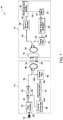
- FIG. 1 is a block diagram representation of a system 10 for contactless power transfer in an implantable device 12 including a two channel field-focusing element 14 in accordance with an embodiment of the invention.
- the implantable device 12 may include a cardiac pacemaker, a neurological simulator, a muscle simulator, or a cochlear implant.
- the system 10 further includes a charging device 16.
- the charging device 16 includes a power source 18 electrically coupled to a first rectifier 20 that converts AC power 22 received from the power source 18 to DC power 24.
- the DC power 24 provided by the first rectifier 20 is supplied to a high frequency inverter 26.
- the high frequency inverter 26 converts the DC power 24 to high frequency AC power 28.
- the frequency of AC power 28 includes frequencies that generate minimum heating of human body tissues.
- the high frequency AC power has a frequency of at least 1MHz.
- the high frequency AC power 28 is further transmitted to a first coil 30 provided in the charging device 16.
- the first coil 30 receives the high frequency AC power 28 and generates a magnetic field 32 based on the high frequency AC power 28.
- the charging device 16 may include a stationary charging device or a portable charging device.
- the magnetic field 32 is focused on to a second coil 34 provided in the implantable device 12 via a field-focusing element 14 disposed between the first coil 30 and the second coil 34.
- the field-focusing element 14 is situated within the implantable device 16.
- the field-focusing element 14 acts as a self-resonant coil having a standing wave current distribution to focus the magnetic field 32 on to the second coil 34 and enhances the coupling between the first coil 30 and the second coil 34 as described in commonly assigned US patent application S/N 12/731497, filed on March 25, 2010 and US patent application S/N 12/914512, filed on October 28, 2010 .
- the field-focusing element 14 includes at least one resonator.
- the at least one resonator may be configured to focus at least one of an electric field, a magnetic field, or an electromagnetic field.
- the at least one resonator includes a split ring structure, a circular loop structure, a Koch fractal, an omega structure, or a spiral structure.
- the at least one resonator is disposed within at least one of a dielectric medium, a magnetic medium, or a magneto-dielectric medium.
- the at least one resonator includes a plurality of resonators with at least two of the plurality of resonators having different resonant frequencies. In one embodiment, the different resonant frequencies enable transfer of power and data signals simultaneously.
- the second coil 34 disposed within the implantable device 16 receives the high frequency AC power 28 from the first coil 30 via the magnetic field 32 generated by the first coil 30.
- the first coil 30 and the second coil 34 are disposed at a distance within a range of about 15 millimeters to about 5 centimeters during the contactless power transfer.
- the second coil 34 transfers the high frequency AC power 28 to the rechargeable battery 36 electrically coupled to the second coil 34 within the implantable device 16.
- a second rectifier 38 may be disposed between the second coil 34 and the rechargeable battery 36 to receive the high frequency AC power 28 from the second coil 34 and convert the AC power 28 to DC power 40 before transferring the DC power 40 to the rechargeable battery 36.
- the DC power 40 transferred to the rechargeable battery 36 is within a range of about 1 microwatt to about 900 milliwatts.
- the rechargeable battery 36 is coupled to a battery management system (BMS) 42 that manages the charging of the rechargeable battery 36.
- BMS battery management system
- the BMS 42 tracks signals 48 representative of the power levels in the rechargeable battery 36 and calculates the power and time required to charge the rechargeable battery 36.
- the BMS 42 regulates a voltage of the DC power 40 entering the rechargeable battery 36.
- the BMS 42 communicates with the high frequency inverter 26 disposed within the charging device 16 to provide data 44 related to the voltage and charge level of the rechargeable battery 36.
- the BMS 42 is communicatively coupled to a high frequency modulator 46 that receives the data signals 44 generated by the BMS 42 and modulates the data signals 44 to provide modulated data signals 50.
- the high frequency modulator 46 is coupled to the second coil 34.
- the second coil 34 converts the modulated data signals 50 to a data magnetic field 52 that is focused on the first coil 30 via the field-focusing element 14.
- the field-focusing element 14 includes a two channel field-focusing element including one unidirectional channel to transfer the AC power 28 and a second channel to transfer the data signals 44.
- a power filter 53 may be disposed between the second coil 34 and the high frequency modulator 46 to isolate the high frequency AC power 28 received from the first coil 30 from the high frequency modulator 46.
- the first coil 30 receives the data magnetic field 52 and transfers signals 150 which are representative of the modulated data signals 50 to a demodulator 54.
- a power filter 56 at the charging device 16 may be used to restrict the high frequency AC power 28 within the first coil 30 from entering the demodulator 54.
- the demodulator 54 extracts signals 144 representative of the data signals 44 from the modulated data signals 150 and transfers the data signals 144 to an inverter controller 58.
- the inverter controller 58 controls the voltage and frequency of power at which the high frequency inverter 26 operates in the charging device 16 by providing control signals 60 based on the data signals 144.
- the inverter controller 58 identifies the voltage and the charge status from the data signals 144 and regulates the inverter operation accordingly to provide desired charging to the rechargeable battery 36.
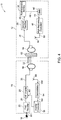
- FIG. 2 is a block diagram representation of an alternate configuration of the system 10 for contactless power transfer in an implantable device 12 including the two channel field-focusing element 14 electrically coupled to the first coil 30 in accordance with an embodiment of the invention.
- the field-focusing element 14 is situated within the charging device 16 rather than within the implantable device.
- FIG. 3 is a block diagram representation of another alternate configuration of the system 10 for contactless power transfer in an implantable device 12 including a two channel field focusing element 14 configured to transfer data signals 44 from battery management system 42 as well as operational data 43 from a controller 45 to an electronic device 47 for medical analysis in accordance with an embodiment of the invention.
- the implantable device 12 includes the controller 45, and the controller 45 monitors and controls the operation of the implantable device 12 and stores the operational data 43.
- the operational data 43 may be used for further analysis such as, for example, prognostic health monitoring of the implantable device 12.
- the controller 45 transfers the operational data 43 to a multiplexer 49 that multiplexes the operational data 43 along with the data signals 44 transferred by the BMS 42 to the multiplexer 49.
- the multiplexer 49 generates a multiplexed signal 51 that is transferred to the high frequency modulator 46 for modulation and is further transmitted to the first coil 30.
- the first coil 30 receives the multiplexed signal 151 representative of the multiplexed signal 51 in the implantable device and transfers the multiplexed signal 151 to a de-multiplexer 55 after demodulation by the de-modulator 54 as described above.
- the de-multiplexer 55 separates the operational data 143 and the data signals 144 from the multiplexed signal 151 representative of the operational data 43 and the data signals 44 in the implantable device 12 respectively.
- the data signals 144 are transferred to the inverter controller 58 as described above and the operational data 143 may be transferred to the electronic device 47 provided outside the charging device 16 for further analysis.
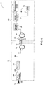
- FIG. 4 is a block diagram representation of a system 10 for contactless power transfer in the implantable device 12 including a single channel field-focusing element 62 in accordance with an embodiment of the invention.
- the single channel field-focusing element 62 focuses high frequency AC power 28 from the first coil 30 to the second coil 34 but, in contrast to the embodiments of FIGs. 1 and 2 , does not transfer modulated data signals 50 from the second coil 34 to the first coil 30.
- the single channel field-focusing element 62 is shown as being situated in the implantable device, the single channel field-focusing element 62 may alternatively be situated in the charging device.
- the modulated data signals 50 received from the high frequency modulator 46 may be transferred to a RF transmitter antenna 64 disposed within the implantable device 12.
- the RF transmitter antenna 64 transmits the modulated data signals 50 to a RF receiver antenna 66 disposed within the charging device 16.
- the RF receiver antenna 66 receives the modulated data signals 150 representative of the modulated data signals 50 from the implantable device 12 and transfers the modulated data signals 150 to the demodulator 54 for further processing as described above.
- FIG. 5 is a block diagram representation an alternate configuration of the system 10 for contactless power transfer in the implantable device 12 wherein no data is required to be transmitted back to the charging device 16.
- the system 10 includes the single channel field-focusing element 62 to focus high frequency AC power 28 from the first coil 30 to the second coil 34. Although the single channel field-focusing element 62 is shown as being situated in the charging device, the single channel field-focusing element 62 may alternatively be situated in the implantable device.
- the high frequency AC power 28 from second coil 34 is converted to DC power by the second rectifier 38, which is transferred to a DC-DC converter 68, which provides DC power 40.
- the DC power 40 is fed to the rechargeable battery 36 for charging.
- the rechargeable battery 36 is coupled to the BMS 42 that regulates the charging of the rechargeable battery 36.
- the BMS 42 is coupled to the DC-DC converter 68 via a feedback loop to regulate the voltage of the DC power 40 entering the rechargeable battery 36 in the implantable device 12.
- the DC-DC converter 68 receives the data signals 44 from the BMS 42 via the feedback loop and adjusts accordingly to provide optimum charging to the rechargeable battery 36.
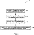
- FIG. 6 is a flow chart representing the steps involved in a method 80 for contactless charging of a rechargeable battery disposed in an implantable device in accordance with an embodiment of the invention.
- the method 80 includes generating a magnetic field via a first coil coupled to a power source in step 82.
- the magnetic field generated by the first coil is focused to a second coil by employing a field-focusing element in step 84.
- the first coil and the second coil are disposed at a distance within a range of about 15 millimeter to about 5 centimeters prior to focusing the magnetic field.
- the first coil transfers power to the second coil via the magnetic field in step 86.
- the power is transferred from the first coil to the second coil within a range of about 1 microwatt to about 900 milliwatts.
- the power from the second coil is transmitted to the rechargeable battery disposed within the implantable device in step 88.
- data signals regarding the implantable device, the state of charge of the rechargeable battery, or both are obtained and transferred through the field-focusing element, first coil and the second coil to a processor situated outside of the implantable device.
- the process is facilitated by having the power and the data signals from the rechargeable battery and implantable device respectively transferred at different resonant frequencies.
- data transfer either is not required or is accomplished via RF transmission.
- the various embodiments of the systems for contactless power transfer in implantable devices described above include a power source, a first coil, a field focusing element and a second coil that enable transfer of power via a contactless medium from the first coil to the second coil.
- the contactless power transfer system enables efficient contactless power transfer between the charging device provided outside the human body and the implantable device disposed inside the human body, for example.
- the contactless power transfer system also maintains the efficiency in case of multiple layers of flesh provided between the first coil and the second coil. This provides a non-destructive method for charging the rechargeable battery disposed within the implantable device and reduces costs and risks to human life during operations.
Landscapes
- Engineering & Computer Science (AREA)
- Computer Networks & Wireless Communication (AREA)
- Power Engineering (AREA)
- Health & Medical Sciences (AREA)
- Signal Processing (AREA)
- General Health & Medical Sciences (AREA)
- Radiology & Medical Imaging (AREA)
- Life Sciences & Earth Sciences (AREA)
- Animal Behavior & Ethology (AREA)
- Public Health (AREA)
- Veterinary Medicine (AREA)
- Nuclear Medicine, Radiotherapy & Molecular Imaging (AREA)
- Biomedical Technology (AREA)
- Physics & Mathematics (AREA)
- General Physics & Mathematics (AREA)
- Medical Informatics (AREA)
- Mathematical Physics (AREA)
- Algebra (AREA)
- Computational Mathematics (AREA)
- Chemical & Material Sciences (AREA)
- Mathematical Analysis (AREA)
- Mathematical Optimization (AREA)
- Medicinal Chemistry (AREA)
- Pure & Applied Mathematics (AREA)
- Business, Economics & Management (AREA)
- Educational Administration (AREA)
- Educational Technology (AREA)
- Theoretical Computer Science (AREA)
- Charge And Discharge Circuits For Batteries Or The Like (AREA)
- Electrotherapy Devices (AREA)
- Prostheses (AREA)
Description
- Embodiments of the present invention relate generally to contactless power transfer systems and more particularly to systems for contactless power transfer in implantable devices.
- Devices may be implanted in a human body for improving the operation of the human body and increasing life expectancy. The devices that may be implanted in the human body are known as implantable devices. Implantable devices operate on batteries, which may comprise non-rechargeable or rechargeable batteries.
- Non-rechargeable batteries typically are replaced after a fixed period of time. Battery replacement surgeries are expensive, complex, and inconvenient to the patient.
- However, use of rechargeable batteries are useful for extending the time between battery replacement surgeries. Conventionally, rechargeable batteries are recharged by an inductive coupling system. The inductive coupling system includes a primary coil and a capacitor placed outside the human body and a secondary coil and a capacitor placed inside the body within the implantable device to receive power from the primary coil and recharge the rechargeable battery. Layers of flesh of the human body sometimes result in distances between the primary coil and the secondary coil that reduce the efficiency of the inductive coupling system. Furthermore, the inductive coupling system requires precise alignment of the external charging device with respect to the secondary coil in the implantable device, making the system difficult to use.
US 2010/148589 A1 relates to contactless power transfer in an implantable device for charging a rechargeable battery within the implantable device using an intermediate resonant object to transfer energy more efficiently.US 2010/308939 A1 relates to a near-field wireless energy transfer system for transmitting electrical power over mid-range distances using one or more repeater resonators. - Hence, there is a need for an improved system and method to address the aforementioned issues.
- The present invention is defined by the appended claims. The examples, embodiments, or aspects of the present description that do not fall within the scope of said claims are merely provided for illustrative purposes and do not form part of the invention. Furthermore, any surgical, therapeutic, or diagnostic methods presented in the present description are provided for illustrative purposes only and do not form part of the present invention.
- In one embodiment, a system for contactless power transfer in an implantable device for charging a rechargeable battery disposed within the implantable device is provided. The system includes a first coil electrically couplable to a power source, wherein the first coil is configured to produce a magnetic field. The system further includes a second coil electrically coupled to the rechargeable battery disposed within the implantable device and configured to receive power from the first coil via the magnetic field and to transfer the power to the rechargeable battery. The system also includes a field focusing element disposed between the first coil and the second coil and configured as a self resonant coil having a standing wave current distribution to focus the magnetic field onto the second coil and enhance the coupling between the first coil and the second coil.
- In another embodiment, a method for contactless charging of a rechargeable battery disposed in an implantable device is provided. The method includes generating a magnetic field via a first coil coupled to a power source. The method further includes focusing the magnetic field to a second coil via a field-focusing element. The method also includes transferring power from the first coil to the second coil via the magnetic field. The method further includes transmitting the power from the second coil to the rechargeable battery disposed within the implantable device.
- These and other features, aspects, and advantages of the present invention will become better understood when the following detailed description is read with reference to the accompanying drawings in which like characters represent like parts throughout the drawings, wherein:
-
FIG. 1 is a block diagram representation of a system for contactless power transfer in an implantable device including a two channel field-focusing element in accordance with an embodiment of the invention. -
FIG. 2 is a block diagram representation of an alternate configuration of a system for contactless power transfer in an implantable device including a two channel field-focusing element electrically coupled to a first coil in accordance with an embodiment of the invention. -
FIG. 3 is a block diagram representation of another alternate configuration of the system for contactless power transfer in an implantable device including a two channel field focusing element configured to transfer data signals and operational data from a controller to an electronic device for medical analysis in accordance with an embodiment of the invention. -
FIG. 4 is a block diagram representation of a system for contactless power transfer in an implantable device including a single channel field-focusing element in accordance with an embodiment of the invention. -
FIG. 5 is a block diagram representation of an alternate configuration of a system for contactless power transfer in an implantable device including a single channel field-focusing element in accordance with another embodiment of the invention. -
FIG. 6 is a flow chart representing the steps involved in a method for contactless charging of a rechargeable battery disposed in an implantable device in accordance with an embodiment of the invention. - Embodiments of the present invention include a system for contactless power transfer in an implantable device for charging a rechargeable battery disposed within the implantable device. The system includes a first coil electrically couplable to a power source. The first coil produces a magnetic field that is coupled to a second coil electrically coupled to the rechargeable battery disposed within the implantable device. The second coil receives the power from the first coil via the magnetic field and further transfers the power to the rechargeable battery. The contactless power transfer system also includes a field-focusing element that is disposed between the first coil and the second coil. The field-focusing element acts as a self-resonant coil having a standing wave current distribution to focus the magnetic field onto the second coil and enhances the coupling between the first coil and the second coil. As used herein, the terms "a" and "an" do not denote a limitation of quantity, but rather denote the presence of at least one of the referenced item.
-
FIG. 1 is a block diagram representation of asystem 10 for contactless power transfer in animplantable device 12 including a two channel field-focusingelement 14 in accordance with an embodiment of the invention. In an exemplary embodiment, theimplantable device 12 may include a cardiac pacemaker, a neurological simulator, a muscle simulator, or a cochlear implant. Thesystem 10 further includes acharging device 16. - The
charging device 16 includes apower source 18 electrically coupled to afirst rectifier 20 that convertsAC power 22 received from thepower source 18 toDC power 24. TheDC power 24 provided by thefirst rectifier 20 is supplied to ahigh frequency inverter 26. Thehigh frequency inverter 26 converts theDC power 24 to highfrequency AC power 28. In one embodiment, the frequency ofAC power 28 includes frequencies that generate minimum heating of human body tissues. In a more specific embodiment, the high frequency AC power has a frequency of at least 1MHz. The highfrequency AC power 28 is further transmitted to afirst coil 30 provided in thecharging device 16. Thefirst coil 30 receives the highfrequency AC power 28 and generates amagnetic field 32 based on the highfrequency AC power 28. Thecharging device 16 may include a stationary charging device or a portable charging device. - The
magnetic field 32 is focused on to asecond coil 34 provided in theimplantable device 12 via a field-focusingelement 14 disposed between thefirst coil 30 and thesecond coil 34. In the embodiment ofFIG. 1 , the field-focusingelement 14 is situated within theimplantable device 16. The field-focusingelement 14 acts as a self-resonant coil having a standing wave current distribution to focus themagnetic field 32 on to thesecond coil 34 and enhances the coupling between thefirst coil 30 and thesecond coil 34 as described in commonly assignedUS patent application S/ N 12/731497, filed on March 25, 2010US patent application S/ N 12/914512, filed on October 28, 2010element 14 includes at least one resonator. The at least one resonator may be configured to focus at least one of an electric field, a magnetic field, or an electromagnetic field. In a more specific embodiment, the at least one resonator includes a split ring structure, a circular loop structure, a Koch fractal, an omega structure, or a spiral structure. In an exemplary embodiment, the at least one resonator is disposed within at least one of a dielectric medium, a magnetic medium, or a magneto-dielectric medium. Furthermore, in a particular embodiment, the at least one resonator includes a plurality of resonators with at least two of the plurality of resonators having different resonant frequencies. In one embodiment, the different resonant frequencies enable transfer of power and data signals simultaneously. - The
second coil 34 disposed within theimplantable device 16, receives the highfrequency AC power 28 from thefirst coil 30 via themagnetic field 32 generated by thefirst coil 30. In a particular embodiment, thefirst coil 30 and thesecond coil 34 are disposed at a distance within a range of about 15 millimeters to about 5 centimeters during the contactless power transfer. Thesecond coil 34 transfers the highfrequency AC power 28 to therechargeable battery 36 electrically coupled to thesecond coil 34 within theimplantable device 16. Asecond rectifier 38 may be disposed between thesecond coil 34 and therechargeable battery 36 to receive the highfrequency AC power 28 from thesecond coil 34 and convert theAC power 28 toDC power 40 before transferring theDC power 40 to therechargeable battery 36. In one embodiment, theDC power 40 transferred to therechargeable battery 36 is within a range of about 1 microwatt to about 900 milliwatts. - In the embodiment of
FIG. 1 , therechargeable battery 36 is coupled to a battery management system (BMS) 42 that manages the charging of therechargeable battery 36. In one embodiment, theBMS 42 tracks signals 48 representative of the power levels in therechargeable battery 36 and calculates the power and time required to charge therechargeable battery 36. In another embodiment, theBMS 42 regulates a voltage of theDC power 40 entering therechargeable battery 36. In some embodiments, theBMS 42 communicates with thehigh frequency inverter 26 disposed within the chargingdevice 16 to providedata 44 related to the voltage and charge level of therechargeable battery 36. - The
BMS 42 is communicatively coupled to ahigh frequency modulator 46 that receives the data signals 44 generated by theBMS 42 and modulates the data signals 44 to provide modulated data signals 50. Thehigh frequency modulator 46 is coupled to thesecond coil 34. Thesecond coil 34 converts the modulated data signals 50 to a datamagnetic field 52 that is focused on thefirst coil 30 via the field-focusingelement 14. In this embodiment, the field-focusingelement 14 includes a two channel field-focusing element including one unidirectional channel to transfer theAC power 28 and a second channel to transfer the data signals 44. Apower filter 53 may be disposed between thesecond coil 34 and thehigh frequency modulator 46 to isolate the highfrequency AC power 28 received from thefirst coil 30 from thehigh frequency modulator 46. - The
first coil 30 receives the datamagnetic field 52 and transfers signals 150 which are representative of the modulated data signals 50 to ademodulator 54. Apower filter 56 at the chargingdevice 16 may be used to restrict the highfrequency AC power 28 within thefirst coil 30 from entering thedemodulator 54. Thedemodulator 54 extracts signals 144 representative of the data signals 44 from the modulated data signals 150 and transfers the data signals 144 to aninverter controller 58. Theinverter controller 58 controls the voltage and frequency of power at which thehigh frequency inverter 26 operates in the chargingdevice 16 by providingcontrol signals 60 based on the data signals 144. Theinverter controller 58 identifies the voltage and the charge status from the data signals 144 and regulates the inverter operation accordingly to provide desired charging to therechargeable battery 36. -
FIG. 2 is a block diagram representation of an alternate configuration of thesystem 10 for contactless power transfer in animplantable device 12 including the two channel field-focusingelement 14 electrically coupled to thefirst coil 30 in accordance with an embodiment of the invention. In the embodiment ofFIG. 2 , the field-focusingelement 14 is situated within the chargingdevice 16 rather than within the implantable device. -
FIG. 3 is a block diagram representation of another alternate configuration of thesystem 10 for contactless power transfer in animplantable device 12 including a two channelfield focusing element 14 configured to transfer data signals 44 frombattery management system 42 as well asoperational data 43 from acontroller 45 to anelectronic device 47 for medical analysis in accordance with an embodiment of the invention. In this embodiment, theimplantable device 12 includes thecontroller 45, and thecontroller 45 monitors and controls the operation of theimplantable device 12 and stores theoperational data 43. Theoperational data 43 may be used for further analysis such as, for example, prognostic health monitoring of theimplantable device 12. In one embodiment, thecontroller 45 transfers theoperational data 43 to amultiplexer 49 that multiplexes theoperational data 43 along with the data signals 44 transferred by theBMS 42 to themultiplexer 49. Themultiplexer 49 generates a multiplexedsignal 51 that is transferred to thehigh frequency modulator 46 for modulation and is further transmitted to thefirst coil 30. - The
first coil 30 receives the multiplexedsignal 151 representative of the multiplexedsignal 51 in the implantable device and transfers the multiplexedsignal 151 to a de-multiplexer 55 after demodulation by the de-modulator 54 as described above. The de-multiplexer 55 separates theoperational data 143 and the data signals 144 from the multiplexedsignal 151 representative of theoperational data 43 and the data signals 44 in theimplantable device 12 respectively. The data signals 144 are transferred to theinverter controller 58 as described above and theoperational data 143 may be transferred to theelectronic device 47 provided outside the chargingdevice 16 for further analysis. -
FIG. 4 is a block diagram representation of asystem 10 for contactless power transfer in theimplantable device 12 including a single channel field-focusingelement 62 in accordance with an embodiment of the invention. The single channel field-focusingelement 62 focuses highfrequency AC power 28 from thefirst coil 30 to thesecond coil 34 but, in contrast to the embodiments ofFIGs. 1 and2 , does not transfer modulated data signals 50 from thesecond coil 34 to thefirst coil 30. Although the single channel field-focusingelement 62 is shown as being situated in the implantable device, the single channel field-focusingelement 62 may alternatively be situated in the charging device. In the embodiment ofFIG. 4 , the modulated data signals 50 received from thehigh frequency modulator 46 may be transferred to aRF transmitter antenna 64 disposed within theimplantable device 12. TheRF transmitter antenna 64 transmits the modulated data signals 50 to aRF receiver antenna 66 disposed within the chargingdevice 16. TheRF receiver antenna 66 receives the modulated data signals 150 representative of the modulated data signals 50 from theimplantable device 12 and transfers the modulated data signals 150 to thedemodulator 54 for further processing as described above. -
FIG. 5 is a block diagram representation an alternate configuration of thesystem 10 for contactless power transfer in theimplantable device 12 wherein no data is required to be transmitted back to the chargingdevice 16. Thesystem 10 includes the single channel field-focusingelement 62 to focus highfrequency AC power 28 from thefirst coil 30 to thesecond coil 34. Although the single channel field-focusingelement 62 is shown as being situated in the charging device, the single channel field-focusingelement 62 may alternatively be situated in the implantable device. The highfrequency AC power 28 fromsecond coil 34 is converted to DC power by thesecond rectifier 38, which is transferred to a DC-DC converter 68, which providesDC power 40. TheDC power 40 is fed to therechargeable battery 36 for charging. Therechargeable battery 36 is coupled to theBMS 42 that regulates the charging of therechargeable battery 36. In the embodiment ofFIG. 5 , theBMS 42 is coupled to the DC-DC converter 68 via a feedback loop to regulate the voltage of theDC power 40 entering therechargeable battery 36 in theimplantable device 12. The DC-DC converter 68 receives the data signals 44 from theBMS 42 via the feedback loop and adjusts accordingly to provide optimum charging to therechargeable battery 36. -
FIG. 6 is a flow chart representing the steps involved in amethod 80 for contactless charging of a rechargeable battery disposed in an implantable device in accordance with an embodiment of the invention. Themethod 80 includes generating a magnetic field via a first coil coupled to a power source instep 82. The magnetic field generated by the first coil is focused to a second coil by employing a field-focusing element instep 84. In one embodiment, the first coil and the second coil are disposed at a distance within a range of about 15 millimeter to about 5 centimeters prior to focusing the magnetic field. The first coil transfers power to the second coil via the magnetic field instep 86. In an exemplary embodiment, the power is transferred from the first coil to the second coil within a range of about 1 microwatt to about 900 milliwatts. The power from the second coil is transmitted to the rechargeable battery disposed within the implantable device instep 88. In one embodiment, data signals regarding the implantable device, the state of charge of the rechargeable battery, or both are obtained and transferred through the field-focusing element, first coil and the second coil to a processor situated outside of the implantable device. In a more specific embodiment, the process is facilitated by having the power and the data signals from the rechargeable battery and implantable device respectively transferred at different resonant frequencies. In still other embodiments, data transfer either is not required or is accomplished via RF transmission. - The various embodiments of the systems for contactless power transfer in implantable devices described above include a power source, a first coil, a field focusing element and a second coil that enable transfer of power via a contactless medium from the first coil to the second coil. The contactless power transfer system enables efficient contactless power transfer between the charging device provided outside the human body and the implantable device disposed inside the human body, for example. The contactless power transfer system also maintains the efficiency in case of multiple layers of flesh provided between the first coil and the second coil. This provides a non-destructive method for charging the rechargeable battery disposed within the implantable device and reduces costs and risks to human life during operations.
- It is to be understood that a skilled artisan will recognize the interchangeability of various features from different embodiments and that the various features described, as well as other known equivalents for each feature, may be mixed and matched by one of ordinary skill in this art to construct additional systems and techniques in accordance with principles of this disclosure.
Claims (14)
- A system (10) for contactless power transfer in an implantable device (12) for charging a rechargeable battery (36) disposed within the implantable device (12) comprising:a first coil (30) adapted to be electrically coupled to a power source (18), wherein the first coil (30) is configured to produce a magnetic field;a second coil (34) adapted to be electrically coupled to the rechargeable battery (36) disposed within the implantable device (12), wherein the second coil is configured to receive power from the first coil (30) via the magnetic field and to transfer the power to the rechargeable battery (36); andan element (14) disposed between the first coil (30) and the second coil (34) configured to enhance the coupling between the first coil (30) and the second coil (34)characterized in that the element (14) comprises a field focusing element (14) disposed between the first coil (30) and the second coil (34), the field focusing element (14) configured as a self resonant coil having a standing wave current distribution to focus the magnetic field onto the second coil (34), wherein the field focusing element comprises a plurality of resonators with at least two of the plurality of resonators having different resonant frequencies, and the different resonant frequencies enable transfer of power and data signals simultaneously.
- The system (10) of claim 1, wherein the field focusing element (14) is disposed within the implantable device (12) or wherein the field focusing element (14) is disposed within a charging device.
- The system (10) of claim 1, wherein the implantable device (12) comprises a cardiac pacemaker, a neurological simulator, a muscle simulator, or a cochlear implant.
- The system (10) of claim 1, wherein the power transferred to the rechargeable battery (36) is within a range of 1 microwatt to 900 milliwatts.
- The system (10) of claim 1, wherein the first coil (30) and the second coil (34) are disposed at a distance within a range of 15 millimeters to 5 centimeters during the contactless power transfer.
- The system (10) of claim 1, further comprising a high frequency inverter (26) coupled between the power source (18) and the first coil (30).
- The system (10) of claim 1, wherein at least one resonator is disposed within at least one of a dielectric medium, a magnetic medium, or a magneto-dielectric medium.
- A method for contactless charging of a rechargeable battery (36) disposed in an implantable device (12) using the system of any one of claims 1-7, the method comprising:generating a magnetic field via a first coil (30) coupled to a power source (18);transferring power from the first coil (30) to the second coil (34) via the magnetic field; andtransmitting the power from the second coil (34) to the rechargeable battery (36) disposed within the implantable devicecharacterized in that the method also comprises:
focusing the magnetic field to a second coil (34) via a field focusing element (14), wherein the field focusing element comprises a plurality of resonators with at least two of the plurality of resonators having different resonant frequencies, and the different resonant frequencies enable transfer of power and data signals simultaneously. - The method of claim 8, wherein transferring the power from the first coil (30) to the second coil (34) comprises transferring the power within a range of 1 microwatt to 900 milliwatts.
- The method of claim 8, further comprising, prior to focusing the magnetic field, disposing the first coil (30) and the second coil (34) at a distance within a range of 15 millimeters to 5 centimeters.
- The method of claim 8, further comprising obtaining data signals regarding the implantable device (12), the state of charge of the rechargeable battery (36), or both, and transferring the data signals to a processor situated outside of the implantable device (12).
- The method of claim 8, wherein the transferring of the data signals further comprising transferring the power to the rechargeable battery (36) and the data signals from the implantable device (12) at different resonant frequencies.
- The method of claim 8, further comprising using the data signals to control the magnetic field generated by the first coil (30).
- The method of claim 8, further comprising obtaining data signals regarding the implantable device (12), the state of charge of the rechargeable battery (36), or both, and using the data signals to control the power transmitted from the second coil (34) to the rechargeable battery (36).
Applications Claiming Priority (2)
| Application Number | Priority Date | Filing Date | Title |
|---|---|---|---|
| US13/052,196 US8849402B2 (en) | 2011-03-21 | 2011-03-21 | System and method for contactless power transfer in implantable devices |
| PCT/US2012/029326 WO2012129061A1 (en) | 2011-03-21 | 2012-03-16 | System and method for contactless power transfer in implantable devices |
Publications (2)
| Publication Number | Publication Date |
|---|---|
| EP2688643A1 EP2688643A1 (en) | 2014-01-29 |
| EP2688643B1 true EP2688643B1 (en) | 2019-03-13 |
Family
ID=45929028
Family Applications (1)
| Application Number | Title | Priority Date | Filing Date |
|---|---|---|---|
| EP12712027.7A Active EP2688643B1 (en) | 2011-03-21 | 2012-03-16 | System and method for contactless power transfer in implantable devices |
Country Status (6)
| Country | Link |
|---|---|
| US (1) | US8849402B2 (en) |
| EP (1) | EP2688643B1 (en) |
| JP (1) | JP5990252B2 (en) |
| KR (1) | KR102013964B1 (en) |
| CN (1) | CN103517735B (en) |
| WO (1) | WO2012129061A1 (en) |
Families Citing this family (54)
| Publication number | Priority date | Publication date | Assignee | Title |
|---|---|---|---|---|
| US8674550B2 (en) | 2010-03-25 | 2014-03-18 | General Electric Company | Contactless power transfer system and method |
| KR101688948B1 (en) * | 2011-05-27 | 2016-12-22 | 엘지전자 주식회사 | Establishing a data communication connection using a wireless power transmission |
| US10525181B2 (en) | 2012-07-27 | 2020-01-07 | Tc1 Llc | Resonant power transfer system and method of estimating system state |
| US9825471B2 (en) | 2012-07-27 | 2017-11-21 | Thoratec Corporation | Resonant power transfer systems with protective algorithm |
| WO2014018973A1 (en) | 2012-07-27 | 2014-01-30 | Thoratec Corporation | Resonant power transmission coils and systems |
| US10383990B2 (en) | 2012-07-27 | 2019-08-20 | Tc1 Llc | Variable capacitor for resonant power transfer systems |
| WO2014018964A2 (en) | 2012-07-27 | 2014-01-30 | Thoratec Corporation | Thermal management for implantable wireless power transfer systems |
| US10291067B2 (en) | 2012-07-27 | 2019-05-14 | Tc1 Llc | Computer modeling for resonant power transfer systems |
| WO2014018967A1 (en) | 2012-07-27 | 2014-01-30 | Thoratec Corporation | Self-tuning resonant power transfer systems |
| US9805863B2 (en) | 2012-07-27 | 2017-10-31 | Thoratec Corporation | Magnetic power transmission utilizing phased transmitter coil arrays and phased receiver coil arrays |
| US9697951B2 (en) * | 2012-08-29 | 2017-07-04 | General Electric Company | Contactless power transfer system |
| US20140114373A1 (en) * | 2012-10-22 | 2014-04-24 | Boston Scientific Neuromodulation Corporation | Intermediate Coupler to Facilitate Charging in an Implantable Medical Device System |
| EP3490102B1 (en) | 2013-03-15 | 2020-08-05 | Tc1 Llc | Malleable tets coil with improved anatomical fit |
| WO2014145664A1 (en) | 2013-03-15 | 2014-09-18 | Thoratec Corporation | Integrated implantable tets housing including fins and coil loops |
| SG11201508501QA (en) * | 2013-04-15 | 2015-11-27 | T&W Engineering As | Ecg monitor with an implantable part |
| WO2014190167A2 (en) * | 2013-05-22 | 2014-11-27 | Deep Brain Innovations LLC | Deep brain stimulator and method of use |
| JP6503351B2 (en) | 2013-07-29 | 2019-04-17 | アルフレッド イー. マン ファウンデーション フォー サイエンティフィック リサーチ | High efficiency magnetic link for implantable devices |
| AU2014296323B2 (en) | 2013-07-29 | 2019-04-04 | Alfred E. Mann Foundation For Scientific Research | Microprocessor controlled class E driver |
| CN103560572B (en) * | 2013-10-18 | 2016-06-01 | 北京航空航天大学 | A kind of implantable cardiac pacemaker magnetic coupling resonance wireless charging device |
| JP6521993B2 (en) | 2013-11-11 | 2019-05-29 | ティーシー1 エルエルシー | Resonance power transmission system having communication |
| WO2015070202A2 (en) | 2013-11-11 | 2015-05-14 | Thoratec Corporation | Hinged resonant power transfer coil |
| WO2015070200A1 (en) * | 2013-11-11 | 2015-05-14 | Thoratec Corporation | Resonant power transfer systems with communications |
| CN104158237B (en) * | 2014-01-20 | 2017-02-08 | 中国海洋大学 | Cardiac pacemaker wireless charging method and apparatus based on magnetic resonance |
| US10610692B2 (en) | 2014-03-06 | 2020-04-07 | Tc1 Llc | Electrical connectors for implantable devices |
| GB2527075A (en) | 2014-03-17 | 2015-12-16 | Daassist As | Percutaneous system, devices and methods |
| US9780575B2 (en) | 2014-08-11 | 2017-10-03 | General Electric Company | System and method for contactless exchange of power |
| EP4213298A1 (en) | 2014-09-22 | 2023-07-19 | Tc1 Llc | Antenna designs for communication between a wirelessly powered implant to an external device outside the body |
| WO2016057525A1 (en) | 2014-10-06 | 2016-04-14 | Thoratec Corporation | Multiaxial connector for implantable devices |
| WO2016057804A1 (en) * | 2014-10-09 | 2016-04-14 | General Electric Company | Method and system for contactless power transfer in a gate driver unit |
| US10052492B2 (en) * | 2015-05-06 | 2018-08-21 | Verily Life Sciences Llc | Replaceable battery for implantable devices |
| US10355512B2 (en) * | 2015-07-23 | 2019-07-16 | Medtronic, Inc. | Focused power transfer for implantable medical device |
| WO2017025606A1 (en) * | 2015-08-12 | 2017-02-16 | Nuheart As | System, apparatus and method for improved contactless power transfer in implantable devices |
| US10148126B2 (en) | 2015-08-31 | 2018-12-04 | Tc1 Llc | Wireless energy transfer system and wearables |
| CN105119357B (en) * | 2015-09-18 | 2018-07-03 | 国网上海市电力公司 | A kind of remote-wireless charging equipment |
| WO2017062552A1 (en) | 2015-10-07 | 2017-04-13 | Tc1 Llc | Resonant power transfer systems having efficiency optimization based on receiver impedance |
| US9931515B2 (en) * | 2015-12-17 | 2018-04-03 | Novartis Ag | Powered case for electro-active medical device battery management |
| US10893847B2 (en) | 2015-12-30 | 2021-01-19 | Nuheart As | Transcatheter insertion system |
| EP3497775B1 (en) | 2016-09-21 | 2022-07-13 | Tc1 Llc | Systems and methods for locating implanted wireless power transmission devices |
| US10335528B2 (en) | 2016-10-07 | 2019-07-02 | Nuheart As | Transcatheter method and system for the delivery of intracorporeal devices |
| US10537672B2 (en) | 2016-10-07 | 2020-01-21 | Nuheart As | Transcatheter device and system for the delivery of intracorporeal devices |
| KR20180076635A (en) * | 2016-12-28 | 2018-07-06 | (주)뉴옵틱스 | Deep brain stimulation and wireless power transmission method thereof |
| US11197990B2 (en) | 2017-01-18 | 2021-12-14 | Tc1 Llc | Systems and methods for transcutaneous power transfer using microneedles |
| US10888646B2 (en) | 2017-04-28 | 2021-01-12 | Nuheart As | Ventricular assist device and method |
| US10537670B2 (en) | 2017-04-28 | 2020-01-21 | Nuheart As | Ventricular assist device and method |
| US10770923B2 (en) | 2018-01-04 | 2020-09-08 | Tc1 Llc | Systems and methods for elastic wireless power transmission devices |
| EP3512087B1 (en) | 2018-01-12 | 2023-01-25 | STMicroelectronics S.r.l. | A galvanically isolated dc-dc converter circuit with data communication, corresponding system and corresponding method |
| IT201800004174A1 (en) | 2018-04-03 | 2019-10-03 | GALVANIC INSULATION CIRCUIT AND SYSTEM, CORRESPONDING PROCEDURE | |
| CN113241860A (en) * | 2018-06-07 | 2021-08-10 | 北京航空航天大学 | Implantable device and wireless power transmission device thereof |
| US11642537B2 (en) | 2019-03-11 | 2023-05-09 | Axonics, Inc. | Charging device with off-center coil |
| CN110164265B (en) * | 2019-05-15 | 2021-04-27 | 河海大学 | Vertical longitudinal wave standing wave experiment measurement device and method |
| US20210393968A1 (en) * | 2020-06-19 | 2021-12-23 | Medtronic, Inc. | Radio frequency energy harvesting |
| US11482888B2 (en) | 2020-06-19 | 2022-10-25 | Medtronic, Inc. | Antenna for use with RF energy harvesting |
| WO2022123531A1 (en) * | 2020-12-10 | 2022-06-16 | Cochlear Limited | Antenna arrangements |
| KR102524396B1 (en) * | 2021-05-03 | 2023-04-24 | 주식회사 토닥 | Cochlear implant system using a compatible external device |
Family Cites Families (20)
| Publication number | Priority date | Publication date | Assignee | Title |
|---|---|---|---|---|
| US6120502A (en) * | 1988-06-13 | 2000-09-19 | Michelson; Gary Karlin | Apparatus and method for the delivery of electrical current for interbody spinal arthrodesis |
| US5690693A (en) | 1995-06-07 | 1997-11-25 | Sulzer Intermedics Inc. | Transcutaneous energy transmission circuit for implantable medical device |
| US6960968B2 (en) | 2002-06-26 | 2005-11-01 | Koninklijke Philips Electronics N.V. | Planar resonator for wireless power transfer |
| US7471986B2 (en) | 2004-02-20 | 2008-12-30 | Cardiac Pacemakers, Inc. | System and method for transmitting energy to and establishing a communications network with one or more implanted devices |
| WO2006048838A1 (en) | 2004-11-08 | 2006-05-11 | Koninklijke Philips Electronics N.V. | Wireless battery status management for medical devices |
| WO2007008646A2 (en) | 2005-07-12 | 2007-01-18 | Massachusetts Institute Of Technology | Wireless non-radiative energy transfer |
| CN103381284B (en) * | 2005-10-14 | 2017-03-01 | 内诺斯蒂姆股份有限公司 | Leadless cardiac pacemaker and system |
| US7880337B2 (en) | 2006-10-25 | 2011-02-01 | Laszlo Farkas | High power wireless resonant energy transfer system |
| TW200824215A (en) | 2006-11-23 | 2008-06-01 | Univ Nat Central | A non-contact type power supply device having load and interval detection |
| CN101682216B (en) * | 2007-03-27 | 2013-06-26 | 麻省理工学院 | Wireless energy transfer |
| US7696722B2 (en) | 2007-03-30 | 2010-04-13 | General Electric Company | Battery powered X-ray detector power system and method |
| JP4453741B2 (en) | 2007-10-25 | 2010-04-21 | トヨタ自動車株式会社 | Electric vehicle and vehicle power supply device |
| US8598743B2 (en) | 2008-09-27 | 2013-12-03 | Witricity Corporation | Resonator arrays for wireless energy transfer |
| US8772973B2 (en) | 2008-09-27 | 2014-07-08 | Witricity Corporation | Integrated resonator-shield structures |
| US8461719B2 (en) * | 2008-09-27 | 2013-06-11 | Witricity Corporation | Wireless energy transfer systems |
| US8362651B2 (en) | 2008-10-01 | 2013-01-29 | Massachusetts Institute Of Technology | Efficient near-field wireless energy transfer using adiabatic system variations |
| JP5324901B2 (en) * | 2008-12-09 | 2013-10-23 | 日立コンシューマエレクトロニクス株式会社 | Non-contact power transmission system |
| US8335569B2 (en) * | 2009-02-10 | 2012-12-18 | Boston Scientific Neuromodulation Corporation | External device for communicating with an implantable medical device having data telemetry and charging integrated in a single housing |
| US8674550B2 (en) | 2010-03-25 | 2014-03-18 | General Electric Company | Contactless power transfer system and method |
| US8174134B2 (en) | 2010-10-28 | 2012-05-08 | General Electric Company | Systems for contactless power transfer |
-
2011
- 2011-03-21 US US13/052,196 patent/US8849402B2/en active Active
-
2012
- 2012-03-16 JP JP2014501153A patent/JP5990252B2/en active Active
- 2012-03-16 KR KR1020137024950A patent/KR102013964B1/en active IP Right Grant
- 2012-03-16 CN CN201280014305.7A patent/CN103517735B/en active Active
- 2012-03-16 WO PCT/US2012/029326 patent/WO2012129061A1/en unknown
- 2012-03-16 EP EP12712027.7A patent/EP2688643B1/en active Active
Non-Patent Citations (1)
| Title |
|---|
| None * |
Also Published As
| Publication number | Publication date |
|---|---|
| JP2014510511A (en) | 2014-04-24 |
| KR20140007447A (en) | 2014-01-17 |
| WO2012129061A1 (en) | 2012-09-27 |
| US8849402B2 (en) | 2014-09-30 |
| EP2688643A1 (en) | 2014-01-29 |
| CN103517735B (en) | 2016-01-20 |
| KR102013964B1 (en) | 2019-08-23 |
| US20120245649A1 (en) | 2012-09-27 |
| JP5990252B2 (en) | 2016-09-07 |
| CN103517735A (en) | 2014-01-15 |
Similar Documents
| Publication | Publication Date | Title |
|---|---|---|
| EP2688643B1 (en) | System and method for contactless power transfer in implantable devices | |
| US8552595B2 (en) | System and method for contactless power transfer in portable image detectors | |
| US11351360B2 (en) | Transcutaneous energy transfer systems | |
| CN103748763B (en) | Implantable medical device and Poewr control method thereof | |
| Ahn et al. | Wireless power transfer with automatic feedback control of load resistance transformation | |
| EP2648800B1 (en) | Portable power charging of implantable medical devices | |
| US9728981B2 (en) | Feedback controlled coil driver for inductive power transfer | |
| KR101882273B1 (en) | Method and apparatus for wireless power reception and method and apparatus for wireless power transmission | |
| EP2453980B1 (en) | Coil system | |
| AU2015247869A1 (en) | Improvements in transcutaneous energy transfer systems | |
| WO2023165163A1 (en) | Electric energy transmission system, and flexible electric energy repeater, relay resonance coil, in-vitro energy controller and in-vivo electric energy receiver thereof | |
| Hached et al. | A Bluetooth-based Low-Energy Qi-compliant battery charger for implantable medical devices | |
| US20120293340A1 (en) | Triggering recharging and wireless transmission of remote patient monitoring device | |
| US10511189B2 (en) | Implantable medical device charging | |
| Smys et al. | Enhanced wireless power transfer system for implantable medical devices | |
| KR20160019258A (en) | The wireless system transferring electric power to organ transplanted to human, the transplanted organ transferred electric power on wireless medium and the method transferring electric power to organ transplanted to human | |
| Newaskar | WIRELESS CHARGER FOR BIOMEDICAL DEVICES | |
| Singh et al. | Green Energy Efficient Wired and Wireless Charging Techniques for IoT Enabled Healthcare Systems | |
| Swain et al. | Development of miniature wireless energy transfer system for implantable pressure sensor | |
| KR20120134072A (en) | System and method for contactless power transfer in portable image detectors | |
| KR20190066127A (en) | Magnetic resonance wireless charging device | |
| Liu | Waveform-optimized wireless power transfer for implantable medical devices | |
| ELDOSOKY et al. | Wireless Power Transfer Based on Spider Web–Coil for Biomedical Implants |
Legal Events
| Date | Code | Title | Description |
|---|---|---|---|
| PUAI | Public reference made under article 153(3) epc to a published international application that has entered the european phase |
Free format text: ORIGINAL CODE: 0009012 |
|
| 17P | Request for examination filed |
Effective date: 20131021 |
|
| AK | Designated contracting states |
Kind code of ref document: A1 Designated state(s): AL AT BE BG CH CY CZ DE DK EE ES FI FR GB GR HR HU IE IS IT LI LT LU LV MC MK MT NL NO PL PT RO RS SE SI SK SM TR |
|
| DAX | Request for extension of the european patent (deleted) | ||
| STAA | Information on the status of an ep patent application or granted ep patent |
Free format text: STATUS: EXAMINATION IS IN PROGRESS |
|
| 17Q | First examination report despatched |
Effective date: 20170328 |
|
| GRAP | Despatch of communication of intention to grant a patent |
Free format text: ORIGINAL CODE: EPIDOSNIGR1 |
|
| STAA | Information on the status of an ep patent application or granted ep patent |
Free format text: STATUS: GRANT OF PATENT IS INTENDED |
|
| RIC1 | Information provided on ipc code assigned before grant |
Ipc: A61N 1/378 20060101AFI20181009BHEP Ipc: H04B 5/00 20060101ALI20181009BHEP Ipc: H02J 5/00 20060101ALI20181009BHEP Ipc: H02J 7/02 20060101ALI20181009BHEP |
|
| INTG | Intention to grant announced |
Effective date: 20181106 |
|
| RIN1 | Information on inventor provided before grant (corrected) |
Inventor name: RAMACHANDRAPANICKER, SOMAKUMAR Inventor name: BHAT, SUMA MEMANA, NARAYANA Inventor name: BOHORI, ADNAN, KUTUBUDDIN |
|
| GRAS | Grant fee paid |
Free format text: ORIGINAL CODE: EPIDOSNIGR3 |
|
| GRAA | (expected) grant |
Free format text: ORIGINAL CODE: 0009210 |
|
| STAA | Information on the status of an ep patent application or granted ep patent |
Free format text: STATUS: THE PATENT HAS BEEN GRANTED |
|
| AK | Designated contracting states |
Kind code of ref document: B1 Designated state(s): AL AT BE BG CH CY CZ DE DK EE ES FI FR GB GR HR HU IE IS IT LI LT LU LV MC MK MT NL NO PL PT RO RS SE SI SK SM TR |
|
| REG | Reference to a national code |
Ref country code: GB Ref legal event code: FG4D |
|
| REG | Reference to a national code |
Ref country code: CH Ref legal event code: EP Ref country code: AT Ref legal event code: REF Ref document number: 1106896 Country of ref document: AT Kind code of ref document: T Effective date: 20190315 |
|
| REG | Reference to a national code |
Ref country code: CH Ref legal event code: NV Representative=s name: VALIPAT S.A. GEVERS SA, CH Ref country code: CH Ref legal event code: PCAR Free format text: NEW ADDRESS: RUE DES NOYERS 11, 2000 NEUCHATEL (CH) |
|
| REG | Reference to a national code |
Ref country code: IE Ref legal event code: FG4D |
|
| REG | Reference to a national code |
Ref country code: DE Ref legal event code: R096 Ref document number: 602012057717 Country of ref document: DE |
|
| REG | Reference to a national code |
Ref country code: NL Ref legal event code: MP Effective date: 20190313 |
|
| REG | Reference to a national code |
Ref country code: LT Ref legal event code: MG4D |
|
| PG25 | Lapsed in a contracting state [announced via postgrant information from national office to epo] |
Ref country code: LT Free format text: LAPSE BECAUSE OF FAILURE TO SUBMIT A TRANSLATION OF THE DESCRIPTION OR TO PAY THE FEE WITHIN THE PRESCRIBED TIME-LIMIT Effective date: 20190313 Ref country code: FI Free format text: LAPSE BECAUSE OF FAILURE TO SUBMIT A TRANSLATION OF THE DESCRIPTION OR TO PAY THE FEE WITHIN THE PRESCRIBED TIME-LIMIT Effective date: 20190313 Ref country code: NO Free format text: LAPSE BECAUSE OF FAILURE TO SUBMIT A TRANSLATION OF THE DESCRIPTION OR TO PAY THE FEE WITHIN THE PRESCRIBED TIME-LIMIT Effective date: 20190613 Ref country code: SE Free format text: LAPSE BECAUSE OF FAILURE TO SUBMIT A TRANSLATION OF THE DESCRIPTION OR TO PAY THE FEE WITHIN THE PRESCRIBED TIME-LIMIT Effective date: 20190313 |
|
| PG25 | Lapsed in a contracting state [announced via postgrant information from national office to epo] |
Ref country code: GR Free format text: LAPSE BECAUSE OF FAILURE TO SUBMIT A TRANSLATION OF THE DESCRIPTION OR TO PAY THE FEE WITHIN THE PRESCRIBED TIME-LIMIT Effective date: 20190614 Ref country code: BG Free format text: LAPSE BECAUSE OF FAILURE TO SUBMIT A TRANSLATION OF THE DESCRIPTION OR TO PAY THE FEE WITHIN THE PRESCRIBED TIME-LIMIT Effective date: 20190613 Ref country code: HR Free format text: LAPSE BECAUSE OF FAILURE TO SUBMIT A TRANSLATION OF THE DESCRIPTION OR TO PAY THE FEE WITHIN THE PRESCRIBED TIME-LIMIT Effective date: 20190313 Ref country code: RS Free format text: LAPSE BECAUSE OF FAILURE TO SUBMIT A TRANSLATION OF THE DESCRIPTION OR TO PAY THE FEE WITHIN THE PRESCRIBED TIME-LIMIT Effective date: 20190313 Ref country code: LV Free format text: LAPSE BECAUSE OF FAILURE TO SUBMIT A TRANSLATION OF THE DESCRIPTION OR TO PAY THE FEE WITHIN THE PRESCRIBED TIME-LIMIT Effective date: 20190313 Ref country code: NL Free format text: LAPSE BECAUSE OF FAILURE TO SUBMIT A TRANSLATION OF THE DESCRIPTION OR TO PAY THE FEE WITHIN THE PRESCRIBED TIME-LIMIT Effective date: 20190313 |
|
| REG | Reference to a national code |
Ref country code: AT Ref legal event code: MK05 Ref document number: 1106896 Country of ref document: AT Kind code of ref document: T Effective date: 20190313 |
|
| PG25 | Lapsed in a contracting state [announced via postgrant information from national office to epo] |
Ref country code: SK Free format text: LAPSE BECAUSE OF FAILURE TO SUBMIT A TRANSLATION OF THE DESCRIPTION OR TO PAY THE FEE WITHIN THE PRESCRIBED TIME-LIMIT Effective date: 20190313 Ref country code: CZ Free format text: LAPSE BECAUSE OF FAILURE TO SUBMIT A TRANSLATION OF THE DESCRIPTION OR TO PAY THE FEE WITHIN THE PRESCRIBED TIME-LIMIT Effective date: 20190313 Ref country code: RO Free format text: LAPSE BECAUSE OF FAILURE TO SUBMIT A TRANSLATION OF THE DESCRIPTION OR TO PAY THE FEE WITHIN THE PRESCRIBED TIME-LIMIT Effective date: 20190313 Ref country code: ES Free format text: LAPSE BECAUSE OF FAILURE TO SUBMIT A TRANSLATION OF THE DESCRIPTION OR TO PAY THE FEE WITHIN THE PRESCRIBED TIME-LIMIT Effective date: 20190313 Ref country code: AL Free format text: LAPSE BECAUSE OF FAILURE TO SUBMIT A TRANSLATION OF THE DESCRIPTION OR TO PAY THE FEE WITHIN THE PRESCRIBED TIME-LIMIT Effective date: 20190313 Ref country code: PT Free format text: LAPSE BECAUSE OF FAILURE TO SUBMIT A TRANSLATION OF THE DESCRIPTION OR TO PAY THE FEE WITHIN THE PRESCRIBED TIME-LIMIT Effective date: 20190713 Ref country code: EE Free format text: LAPSE BECAUSE OF FAILURE TO SUBMIT A TRANSLATION OF THE DESCRIPTION OR TO PAY THE FEE WITHIN THE PRESCRIBED TIME-LIMIT Effective date: 20190313 Ref country code: IT Free format text: LAPSE BECAUSE OF FAILURE TO SUBMIT A TRANSLATION OF THE DESCRIPTION OR TO PAY THE FEE WITHIN THE PRESCRIBED TIME-LIMIT Effective date: 20190313 |
|
| PG25 | Lapsed in a contracting state [announced via postgrant information from national office to epo] |
Ref country code: SM Free format text: LAPSE BECAUSE OF FAILURE TO SUBMIT A TRANSLATION OF THE DESCRIPTION OR TO PAY THE FEE WITHIN THE PRESCRIBED TIME-LIMIT Effective date: 20190313 Ref country code: LU Free format text: LAPSE BECAUSE OF NON-PAYMENT OF DUE FEES Effective date: 20190316 Ref country code: PL Free format text: LAPSE BECAUSE OF FAILURE TO SUBMIT A TRANSLATION OF THE DESCRIPTION OR TO PAY THE FEE WITHIN THE PRESCRIBED TIME-LIMIT Effective date: 20190313 |
|
| REG | Reference to a national code |
Ref country code: BE Ref legal event code: MM Effective date: 20190331 |
|
| REG | Reference to a national code |
Ref country code: DE Ref legal event code: R097 Ref document number: 602012057717 Country of ref document: DE |
|
| PG25 | Lapsed in a contracting state [announced via postgrant information from national office to epo] |
Ref country code: IS Free format text: LAPSE BECAUSE OF FAILURE TO SUBMIT A TRANSLATION OF THE DESCRIPTION OR TO PAY THE FEE WITHIN THE PRESCRIBED TIME-LIMIT Effective date: 20190713 Ref country code: AT Free format text: LAPSE BECAUSE OF FAILURE TO SUBMIT A TRANSLATION OF THE DESCRIPTION OR TO PAY THE FEE WITHIN THE PRESCRIBED TIME-LIMIT Effective date: 20190313 |
|
| PLBE | No opposition filed within time limit |
Free format text: ORIGINAL CODE: 0009261 |
|
| STAA | Information on the status of an ep patent application or granted ep patent |
Free format text: STATUS: NO OPPOSITION FILED WITHIN TIME LIMIT |
|
| PG25 | Lapsed in a contracting state [announced via postgrant information from national office to epo] |
Ref country code: IE Free format text: LAPSE BECAUSE OF NON-PAYMENT OF DUE FEES Effective date: 20190316 Ref country code: MC Free format text: LAPSE BECAUSE OF FAILURE TO SUBMIT A TRANSLATION OF THE DESCRIPTION OR TO PAY THE FEE WITHIN THE PRESCRIBED TIME-LIMIT Effective date: 20190313 Ref country code: DK Free format text: LAPSE BECAUSE OF FAILURE TO SUBMIT A TRANSLATION OF THE DESCRIPTION OR TO PAY THE FEE WITHIN THE PRESCRIBED TIME-LIMIT Effective date: 20190313 |
|
| 26N | No opposition filed |
Effective date: 20191216 |
|
| GBPC | Gb: european patent ceased through non-payment of renewal fee |
Effective date: 20190613 |
|
| PG25 | Lapsed in a contracting state [announced via postgrant information from national office to epo] |
Ref country code: SI Free format text: LAPSE BECAUSE OF FAILURE TO SUBMIT A TRANSLATION OF THE DESCRIPTION OR TO PAY THE FEE WITHIN THE PRESCRIBED TIME-LIMIT Effective date: 20190313 Ref country code: BE Free format text: LAPSE BECAUSE OF NON-PAYMENT OF DUE FEES Effective date: 20190331 |
|
| PG25 | Lapsed in a contracting state [announced via postgrant information from national office to epo] |
Ref country code: TR Free format text: LAPSE BECAUSE OF FAILURE TO SUBMIT A TRANSLATION OF THE DESCRIPTION OR TO PAY THE FEE WITHIN THE PRESCRIBED TIME-LIMIT Effective date: 20190313 |
|
| PG25 | Lapsed in a contracting state [announced via postgrant information from national office to epo] |
Ref country code: GB Free format text: LAPSE BECAUSE OF NON-PAYMENT OF DUE FEES Effective date: 20190613 |
|
| PG25 | Lapsed in a contracting state [announced via postgrant information from national office to epo] |
Ref country code: MT Free format text: LAPSE BECAUSE OF NON-PAYMENT OF DUE FEES Effective date: 20190316 |
|
| PG25 | Lapsed in a contracting state [announced via postgrant information from national office to epo] |
Ref country code: CY Free format text: LAPSE BECAUSE OF FAILURE TO SUBMIT A TRANSLATION OF THE DESCRIPTION OR TO PAY THE FEE WITHIN THE PRESCRIBED TIME-LIMIT Effective date: 20190313 |
|
| PG25 | Lapsed in a contracting state [announced via postgrant information from national office to epo] |
Ref country code: HU Free format text: LAPSE BECAUSE OF FAILURE TO SUBMIT A TRANSLATION OF THE DESCRIPTION OR TO PAY THE FEE WITHIN THE PRESCRIBED TIME-LIMIT; INVALID AB INITIO Effective date: 20120316 |
|
| PG25 | Lapsed in a contracting state [announced via postgrant information from national office to epo] |
Ref country code: MK Free format text: LAPSE BECAUSE OF FAILURE TO SUBMIT A TRANSLATION OF THE DESCRIPTION OR TO PAY THE FEE WITHIN THE PRESCRIBED TIME-LIMIT Effective date: 20190313 |
|
| PGFP | Annual fee paid to national office [announced via postgrant information from national office to epo] |
Ref country code: FR Payment date: 20230222 Year of fee payment: 12 |
|
| P01 | Opt-out of the competence of the unified patent court (upc) registered |
Effective date: 20230528 |
|
| PGFP | Annual fee paid to national office [announced via postgrant information from national office to epo] |
Ref country code: CH Payment date: 20230401 Year of fee payment: 12 |
|
| PGFP | Annual fee paid to national office [announced via postgrant information from national office to epo] |
Ref country code: DE Payment date: 20240220 Year of fee payment: 13 |