EP2682073A1 - Knee prosthesis system with side-mounted augments - Google Patents
Knee prosthesis system with side-mounted augments Download PDFInfo
- Publication number
- EP2682073A1 EP2682073A1 EP13174067.2A EP13174067A EP2682073A1 EP 2682073 A1 EP2682073 A1 EP 2682073A1 EP 13174067 A EP13174067 A EP 13174067A EP 2682073 A1 EP2682073 A1 EP 2682073A1
- Authority
- EP
- European Patent Office
- Prior art keywords
- augment
- distal
- posterior
- articulation component
- distal femoral
- Prior art date
- Legal status (The legal status is an assumption and is not a legal conclusion. Google has not performed a legal analysis and makes no representation as to the accuracy of the status listed.)
- Granted
Links
- 210000003127 knee Anatomy 0.000 title claims abstract description 24
- 239000004568 cement Substances 0.000 claims description 55
- 230000001154 acute effect Effects 0.000 claims description 13
- 210000000988 bone and bone Anatomy 0.000 description 14
- 210000000689 upper leg Anatomy 0.000 description 12
- 239000007943 implant Substances 0.000 description 11
- 210000000629 knee joint Anatomy 0.000 description 4
- 210000004417 patella Anatomy 0.000 description 4
- 238000001356 surgical procedure Methods 0.000 description 4
- 210000002303 tibia Anatomy 0.000 description 3
- 210000003484 anatomy Anatomy 0.000 description 2
- 230000007812 deficiency Effects 0.000 description 2
- 201000010099 disease Diseases 0.000 description 2
- 208000037265 diseases, disorders, signs and symptoms Diseases 0.000 description 2
- 238000002513 implantation Methods 0.000 description 2
- 208000014674 injury Diseases 0.000 description 2
- 230000007246 mechanism Effects 0.000 description 2
- 210000002435 tendon Anatomy 0.000 description 2
- 230000008733 trauma Effects 0.000 description 2
- 206010058029 Arthrofibrosis Diseases 0.000 description 1
- 206010065687 Bone loss Diseases 0.000 description 1
- 208000003076 Osteolysis Diseases 0.000 description 1
- 229910001069 Ti alloy Inorganic materials 0.000 description 1
- 230000002411 adverse Effects 0.000 description 1
- 238000011882 arthroplasty Methods 0.000 description 1
- 230000003190 augmentative effect Effects 0.000 description 1
- 239000002639 bone cement Substances 0.000 description 1
- 239000000788 chromium alloy Substances 0.000 description 1
- 210000004439 collateral ligament Anatomy 0.000 description 1
- 238000010276 construction Methods 0.000 description 1
- 208000029791 lytic metastatic bone lesion Diseases 0.000 description 1
- 229910052751 metal Inorganic materials 0.000 description 1
- 239000002184 metal Substances 0.000 description 1
- 150000002739 metals Chemical class 0.000 description 1
- 238000000034 method Methods 0.000 description 1
- 210000003205 muscle Anatomy 0.000 description 1
- 210000002967 posterior cruciate ligament Anatomy 0.000 description 1
- 238000000926 separation method Methods 0.000 description 1
- 210000000824 sesamoid bone Anatomy 0.000 description 1
- 239000010421 standard material Substances 0.000 description 1
- 210000001519 tissue Anatomy 0.000 description 1
- 238000011883 total knee arthroplasty Methods 0.000 description 1
Images


Classifications
-
- A—HUMAN NECESSITIES
- A61—MEDICAL OR VETERINARY SCIENCE; HYGIENE
- A61F—FILTERS IMPLANTABLE INTO BLOOD VESSELS; PROSTHESES; DEVICES PROVIDING PATENCY TO, OR PREVENTING COLLAPSING OF, TUBULAR STRUCTURES OF THE BODY, e.g. STENTS; ORTHOPAEDIC, NURSING OR CONTRACEPTIVE DEVICES; FOMENTATION; TREATMENT OR PROTECTION OF EYES OR EARS; BANDAGES, DRESSINGS OR ABSORBENT PADS; FIRST-AID KITS
- A61F2/00—Filters implantable into blood vessels; Prostheses, i.e. artificial substitutes or replacements for parts of the body; Appliances for connecting them with the body; Devices providing patency to, or preventing collapsing of, tubular structures of the body, e.g. stents
- A61F2/02—Prostheses implantable into the body
- A61F2/30—Joints
- A61F2/30721—Accessories
- A61F2/30734—Modular inserts, sleeves or augments, e.g. placed on proximal part of stem for fixation purposes or wedges for bridging a bone defect
-
- A—HUMAN NECESSITIES
- A61—MEDICAL OR VETERINARY SCIENCE; HYGIENE
- A61F—FILTERS IMPLANTABLE INTO BLOOD VESSELS; PROSTHESES; DEVICES PROVIDING PATENCY TO, OR PREVENTING COLLAPSING OF, TUBULAR STRUCTURES OF THE BODY, e.g. STENTS; ORTHOPAEDIC, NURSING OR CONTRACEPTIVE DEVICES; FOMENTATION; TREATMENT OR PROTECTION OF EYES OR EARS; BANDAGES, DRESSINGS OR ABSORBENT PADS; FIRST-AID KITS
- A61F2/00—Filters implantable into blood vessels; Prostheses, i.e. artificial substitutes or replacements for parts of the body; Appliances for connecting them with the body; Devices providing patency to, or preventing collapsing of, tubular structures of the body, e.g. stents
- A61F2/02—Prostheses implantable into the body
- A61F2/30—Joints
- A61F2/38—Joints for elbows or knees
- A61F2/3859—Femoral components
-
- A—HUMAN NECESSITIES
- A61—MEDICAL OR VETERINARY SCIENCE; HYGIENE
- A61F—FILTERS IMPLANTABLE INTO BLOOD VESSELS; PROSTHESES; DEVICES PROVIDING PATENCY TO, OR PREVENTING COLLAPSING OF, TUBULAR STRUCTURES OF THE BODY, e.g. STENTS; ORTHOPAEDIC, NURSING OR CONTRACEPTIVE DEVICES; FOMENTATION; TREATMENT OR PROTECTION OF EYES OR EARS; BANDAGES, DRESSINGS OR ABSORBENT PADS; FIRST-AID KITS
- A61F2/00—Filters implantable into blood vessels; Prostheses, i.e. artificial substitutes or replacements for parts of the body; Appliances for connecting them with the body; Devices providing patency to, or preventing collapsing of, tubular structures of the body, e.g. stents
- A61F2/02—Prostheses implantable into the body
- A61F2/30—Joints
- A61F2/38—Joints for elbows or knees
- A61F2/3886—Joints for elbows or knees for stabilising knees against anterior or lateral dislocations
-
- A—HUMAN NECESSITIES
- A61—MEDICAL OR VETERINARY SCIENCE; HYGIENE
- A61F—FILTERS IMPLANTABLE INTO BLOOD VESSELS; PROSTHESES; DEVICES PROVIDING PATENCY TO, OR PREVENTING COLLAPSING OF, TUBULAR STRUCTURES OF THE BODY, e.g. STENTS; ORTHOPAEDIC, NURSING OR CONTRACEPTIVE DEVICES; FOMENTATION; TREATMENT OR PROTECTION OF EYES OR EARS; BANDAGES, DRESSINGS OR ABSORBENT PADS; FIRST-AID KITS
- A61F2/00—Filters implantable into blood vessels; Prostheses, i.e. artificial substitutes or replacements for parts of the body; Appliances for connecting them with the body; Devices providing patency to, or preventing collapsing of, tubular structures of the body, e.g. stents
- A61F2/02—Prostheses implantable into the body
- A61F2/30—Joints
- A61F2002/30001—Additional features of subject-matter classified in A61F2/28, A61F2/30 and subgroups thereof
- A61F2002/30316—The prosthesis having different structural features at different locations within the same prosthesis; Connections between prosthetic parts; Special structural features of bone or joint prostheses not otherwise provided for
- A61F2002/30329—Connections or couplings between prosthetic parts, e.g. between modular parts; Connecting elements
- A61F2002/30331—Connections or couplings between prosthetic parts, e.g. between modular parts; Connecting elements made by longitudinally pushing a protrusion into a complementarily-shaped recess, e.g. held by friction fit
- A61F2002/30332—Conically- or frustoconically-shaped protrusion and recess
-
- A—HUMAN NECESSITIES
- A61—MEDICAL OR VETERINARY SCIENCE; HYGIENE
- A61F—FILTERS IMPLANTABLE INTO BLOOD VESSELS; PROSTHESES; DEVICES PROVIDING PATENCY TO, OR PREVENTING COLLAPSING OF, TUBULAR STRUCTURES OF THE BODY, e.g. STENTS; ORTHOPAEDIC, NURSING OR CONTRACEPTIVE DEVICES; FOMENTATION; TREATMENT OR PROTECTION OF EYES OR EARS; BANDAGES, DRESSINGS OR ABSORBENT PADS; FIRST-AID KITS
- A61F2/00—Filters implantable into blood vessels; Prostheses, i.e. artificial substitutes or replacements for parts of the body; Appliances for connecting them with the body; Devices providing patency to, or preventing collapsing of, tubular structures of the body, e.g. stents
- A61F2/02—Prostheses implantable into the body
- A61F2/30—Joints
- A61F2002/30001—Additional features of subject-matter classified in A61F2/28, A61F2/30 and subgroups thereof
- A61F2002/30316—The prosthesis having different structural features at different locations within the same prosthesis; Connections between prosthetic parts; Special structural features of bone or joint prostheses not otherwise provided for
- A61F2002/30329—Connections or couplings between prosthetic parts, e.g. between modular parts; Connecting elements
- A61F2002/30331—Connections or couplings between prosthetic parts, e.g. between modular parts; Connecting elements made by longitudinally pushing a protrusion into a complementarily-shaped recess, e.g. held by friction fit
- A61F2002/30362—Connections or couplings between prosthetic parts, e.g. between modular parts; Connecting elements made by longitudinally pushing a protrusion into a complementarily-shaped recess, e.g. held by friction fit with possibility of relative movement between the protrusion and the recess
- A61F2002/30364—Rotation about the common longitudinal axis
- A61F2002/30367—Rotation about the common longitudinal axis with additional means for preventing said rotation
-
- A—HUMAN NECESSITIES
- A61—MEDICAL OR VETERINARY SCIENCE; HYGIENE
- A61F—FILTERS IMPLANTABLE INTO BLOOD VESSELS; PROSTHESES; DEVICES PROVIDING PATENCY TO, OR PREVENTING COLLAPSING OF, TUBULAR STRUCTURES OF THE BODY, e.g. STENTS; ORTHOPAEDIC, NURSING OR CONTRACEPTIVE DEVICES; FOMENTATION; TREATMENT OR PROTECTION OF EYES OR EARS; BANDAGES, DRESSINGS OR ABSORBENT PADS; FIRST-AID KITS
- A61F2/00—Filters implantable into blood vessels; Prostheses, i.e. artificial substitutes or replacements for parts of the body; Appliances for connecting them with the body; Devices providing patency to, or preventing collapsing of, tubular structures of the body, e.g. stents
- A61F2/02—Prostheses implantable into the body
- A61F2/30—Joints
- A61F2002/30001—Additional features of subject-matter classified in A61F2/28, A61F2/30 and subgroups thereof
- A61F2002/30316—The prosthesis having different structural features at different locations within the same prosthesis; Connections between prosthetic parts; Special structural features of bone or joint prostheses not otherwise provided for
- A61F2002/30329—Connections or couplings between prosthetic parts, e.g. between modular parts; Connecting elements
- A61F2002/30433—Connections or couplings between prosthetic parts, e.g. between modular parts; Connecting elements using additional screws, bolts, dowels, rivets or washers e.g. connecting screws
-
- A—HUMAN NECESSITIES
- A61—MEDICAL OR VETERINARY SCIENCE; HYGIENE
- A61F—FILTERS IMPLANTABLE INTO BLOOD VESSELS; PROSTHESES; DEVICES PROVIDING PATENCY TO, OR PREVENTING COLLAPSING OF, TUBULAR STRUCTURES OF THE BODY, e.g. STENTS; ORTHOPAEDIC, NURSING OR CONTRACEPTIVE DEVICES; FOMENTATION; TREATMENT OR PROTECTION OF EYES OR EARS; BANDAGES, DRESSINGS OR ABSORBENT PADS; FIRST-AID KITS
- A61F2/00—Filters implantable into blood vessels; Prostheses, i.e. artificial substitutes or replacements for parts of the body; Appliances for connecting them with the body; Devices providing patency to, or preventing collapsing of, tubular structures of the body, e.g. stents
- A61F2/02—Prostheses implantable into the body
- A61F2/30—Joints
- A61F2/30721—Accessories
- A61F2/30734—Modular inserts, sleeves or augments, e.g. placed on proximal part of stem for fixation purposes or wedges for bridging a bone defect
- A61F2002/30736—Augments or augmentation pieces, e.g. wedges or blocks for bridging a bone defect
-
- A—HUMAN NECESSITIES
- A61—MEDICAL OR VETERINARY SCIENCE; HYGIENE
- A61F—FILTERS IMPLANTABLE INTO BLOOD VESSELS; PROSTHESES; DEVICES PROVIDING PATENCY TO, OR PREVENTING COLLAPSING OF, TUBULAR STRUCTURES OF THE BODY, e.g. STENTS; ORTHOPAEDIC, NURSING OR CONTRACEPTIVE DEVICES; FOMENTATION; TREATMENT OR PROTECTION OF EYES OR EARS; BANDAGES, DRESSINGS OR ABSORBENT PADS; FIRST-AID KITS
- A61F2/00—Filters implantable into blood vessels; Prostheses, i.e. artificial substitutes or replacements for parts of the body; Appliances for connecting them with the body; Devices providing patency to, or preventing collapsing of, tubular structures of the body, e.g. stents
- A61F2/02—Prostheses implantable into the body
- A61F2/30—Joints
- A61F2/30767—Special external or bone-contacting surface, e.g. coating for improving bone ingrowth
- A61F2/30771—Special external or bone-contacting surface, e.g. coating for improving bone ingrowth applied in original prostheses, e.g. holes or grooves
- A61F2002/30878—Special external or bone-contacting surface, e.g. coating for improving bone ingrowth applied in original prostheses, e.g. holes or grooves with non-sharp protrusions, for instance contacting the bone for anchoring, e.g. keels, pegs, pins, posts, shanks, stems, struts
-
- A—HUMAN NECESSITIES
- A61—MEDICAL OR VETERINARY SCIENCE; HYGIENE
- A61F—FILTERS IMPLANTABLE INTO BLOOD VESSELS; PROSTHESES; DEVICES PROVIDING PATENCY TO, OR PREVENTING COLLAPSING OF, TUBULAR STRUCTURES OF THE BODY, e.g. STENTS; ORTHOPAEDIC, NURSING OR CONTRACEPTIVE DEVICES; FOMENTATION; TREATMENT OR PROTECTION OF EYES OR EARS; BANDAGES, DRESSINGS OR ABSORBENT PADS; FIRST-AID KITS
- A61F2/00—Filters implantable into blood vessels; Prostheses, i.e. artificial substitutes or replacements for parts of the body; Appliances for connecting them with the body; Devices providing patency to, or preventing collapsing of, tubular structures of the body, e.g. stents
- A61F2/02—Prostheses implantable into the body
- A61F2/30—Joints
- A61F2/46—Special tools or methods for implanting or extracting artificial joints, accessories, bone grafts or substitutes, or particular adaptations therefor
- A61F2/4603—Special tools or methods for implanting or extracting artificial joints, accessories, bone grafts or substitutes, or particular adaptations therefor for insertion or extraction of endoprosthetic joints or of accessories thereof
- A61F2002/4619—Special tools or methods for implanting or extracting artificial joints, accessories, bone grafts or substitutes, or particular adaptations therefor for insertion or extraction of endoprosthetic joints or of accessories thereof for extraction
-
- A—HUMAN NECESSITIES
- A61—MEDICAL OR VETERINARY SCIENCE; HYGIENE
- A61F—FILTERS IMPLANTABLE INTO BLOOD VESSELS; PROSTHESES; DEVICES PROVIDING PATENCY TO, OR PREVENTING COLLAPSING OF, TUBULAR STRUCTURES OF THE BODY, e.g. STENTS; ORTHOPAEDIC, NURSING OR CONTRACEPTIVE DEVICES; FOMENTATION; TREATMENT OR PROTECTION OF EYES OR EARS; BANDAGES, DRESSINGS OR ABSORBENT PADS; FIRST-AID KITS
- A61F2/00—Filters implantable into blood vessels; Prostheses, i.e. artificial substitutes or replacements for parts of the body; Appliances for connecting them with the body; Devices providing patency to, or preventing collapsing of, tubular structures of the body, e.g. stents
- A61F2/02—Prostheses implantable into the body
- A61F2/30—Joints
- A61F2/46—Special tools or methods for implanting or extracting artificial joints, accessories, bone grafts or substitutes, or particular adaptations therefor
- A61F2002/4631—Special tools or methods for implanting or extracting artificial joints, accessories, bone grafts or substitutes, or particular adaptations therefor the prosthesis being specially adapted for being cemented
Definitions
- the present invention relates to prosthetic joints, and more particularly to a modular prosthetic knee joint system that includes augments.
- the knee joint basically consists of the bone interface of the distal end of the femur and the proximal end of the tibia.
- the patella appears to cover or at least partially protect this interface.
- the patella is a sesamoid bone within the tendon of the long muscle (quadriceps) on the front of the thigh. This tendon inserts into the tibial tuberosity and the posterior surface of the patella is smooth and glides over the femur.
- the femur is configured with two knob like processes (the medial condyle and the lateral condyle) which are substantially smooth and which articulate with the medial plateau and the lateral plateau of the tibia, respectively.
- the plateaus of the tibia are substantially smooth and slightly cupped thereby providing a slight receptacle for receipt of the femoral condyles.
- a prosthetic replacement of the damaged joint may be necessary to relieve pain and to restore normal use to the joint.
- the entire knee joint is replaced by means of a surgical procedure that involves removal of the surfaces of the corresponding damaged bones and replacement of these surfaces with prosthetic implants.
- This replacement of a native joint with a prosthetic joint is referred to as a primary total-knee arthroplasty.
- the primary knee prostheses fails. Failure can result from many causes, including wear, aseptic loosening, osteolysis, ligamentous instability, arthrofibrosis and patellofemoral complications.
- revision knee surgery may be necessary.
- the primary knee prosthesis is removed and replaced with components of a revision prosthetic knee system.
- Knee implant systems for both primary and revision applications are available from a variety of manufacturers, including DePuy Orthopaedics Inc of Warsaw, Indiana, USA. DePuy and others offer several different systems for both primary and revision applications.
- DePuy Orthopaedics market knee systems under the trade marks PFC SIGMA, LCS and S-ROM. Each of these orthopaedic knee systems includes several components, some appropriate for use in primary knee arthroplasty and some appropriate for use in revision surgery.
- DePuy Orthopaedics also offers other orthopaedic implant systems for other applications.
- One such system is marketed under the trade mark LPS.
- the LPS system is provided for use in cases of severe trauma and disease. In such cases, the trauma or disease can lead to significant amounts of bone loss.
- the LPS system provides components that can replace all or significant portions of a particular bone, such as the femur. Details of the DePuy LPS system are disclosed in US-A-2003/0204267 .
- Prosthetic knee implant systems have commonly included femoral augments for use on the distal and posterior bone-facing surfaces of the femoral implant components. Examples of such augments are disclosed in US-5984969 and US-6005018 . Such components serve to augment the inferior and posterior portions of the femoral component to add additional thickness to compensate for the lack of sufficient boney tissue, allowing the joint line to be distalized.
- such augments are commonly connected to the bone-facing surfaces of the distal femoral articulation components through screws or pins inserted superiorly or anteriorly from the bone-facing surfaces of the augments and threaded into threaded openings or collets or other receptacles received in openings in the bone-facing surface of the distal femoral articulation components.
- a special tool may be required to connect the augment to the posterior condylar bone-facing surface of the distal femoral articulation component; for example, a wobble driver tip to facilitate access across the femoral anterior flange.
- the augments and distal femoral articulation components cannot be disassembled until after the entire assembly is removed from the distal femur because the connection mechanisms are no longer accessible.
- the present invention provides a modular knee implant system that allows the surgeon to separate distal femoral articulation components and augments from an implanted assembly prior to removal of the assembly from the bone.
- the modular knee implant system of the present invention also allows for quick and simple connection of augments to distal femoral articulation components.
- the invention provides a modular knee prosthesis system which includes a distal femoral articulation component, an augment and a first connector for securing the augment to the distal femoral articulation component.
- the distal femoral articulation component has a pair of curved distal condylar articulating surfaces, a pair of curved posterior condylar articulating surfaces, a distal bone-facing surface and a posterior bone-facing surface.
- the augment is sized and shaped to be received on one of the bone-facing surfaces of the distal femoral articulation component.
- the augment includes a first surface, a second surface spaced from and generally opposite to the first surface, side surfaces extending between and connecting the first surface and the second surface, and a body between the first and second surface. At least one of the side surfaces has an opening into a bore extending from the side surface through the body and through another surface of the augment.
- the distal femoral articulation component has an opening to receive the connector to selectively mount the augment to the distal femoral articulation component.
- the bore of the augment has a central longitudinal axis that defines an acute angle with at least one of the first surface and the second surface of the augment.
- the augment is a distal femoral augment
- the central longitudinal axis of the bore defines an acute angle with the second surface of the augment and the opening in the distal femoral articulation component is in the distal bone-facing surface of the distal femoral articulation component.
- the side surfaces of the augment may then include a medial surface and a lateral surface and the opening into the bore may be in one of the medial surface and lateral surface.
- the bore in the augment has a central longitudinal axis between the first surface and the second surface of the augment.
- the augment is a posterior femoral augment.
- the side surfaces of the augment may then include a medial surface and a lateral surface and the opening into the bore may be in one of the medial surface and lateral surface.
- the distal femoral articulation component may then be a posterior stabilized component including a box having a box top wall and a box side wall; the box side wall extends from the box top wall to at least one of the distal bone-facing surface and a posterior bone-facing surface and the opening in the distal femoral articulation component is in the box side wall.
- the connecting element may comprise a screw or bolt.
- the distal bone-facing surface of the distal femoral articulation component may have a recessed distal cement pocket and the posterior bone-facing surface of the distal femoral articulation component may have a recessed posterior cement pocket.
- the second surface of the augment may include a plurality of protruding feet sized, shaped and positioned to be received in a unique position within one of the cement pockets when the augment is assembled with the distal femoral articulation component to locate the augment positively with respect to the cement pocket.
- the recessed cement pocket may be tapered so that the pocket is deeper at one end and the feet of the augment may be shaped so that the outermost surfaces of the feet lie in a plane that defines an acute angle with the first surface of the augment.
- the first surface of the augment may have a recessed cement pocket.
- the invention also provides a modular knee prosthesis system which comprises a distal femoral articulation component, a distal augment, a posterior augment and a first connector for securing at least one of the augments to the distal femoral articulation component through the bore of the augment and the opening in the distal femoral articulation component.
- the distal femoral articulation component has a pair of curved distal condylar articulating surfaces, a pair of curved posterior condylar articulating surfaces, a distal bone-facing surface, a posterior bone-facing surface and an opening.
- the distal augment is sized and shaped to be received on the distal bone-facing surface of the distal femoral articulation component and includes a first surface, a second surface spaced from and generally opposite to the first surface and side surfaces extending between and connecting the first surface and the second surface.
- the distal augment has a body between the first and second surface and at least one of the side surfaces has an opening into a bore extending from the side surface through the body and through another surface of the distal augment.
- the posterior augment is sized and shaped to be received on the posterior bone-facing surface of the distal femoral articulation component and includes a first surface, a second surface spaced from and generally opposite to the first surface and side surfaces extending between and connecting the first surface and the second surface.
- the posterior augment has a body between the first and second surfaces and at least one of the side surfaces has an opening into a bore extending from the side surface through the body and through another surface of the posterior augment.
- the distal femoral articulation component is a posterior stabilized component including a box having a box top wall and a box side wall, the box side wall extending from the box top wall to at least one of the distal bone-facing surface and a posterior bone-facing surface of the distal femoral articulation component.
- the opening in the distal femoral articulation component may then be in the box side wall.
- the bore in at least one of the augments may have a central longitudinal axis between the first surface and the second surface of the posterior augment.
- the opening in the box side wall may be positioned and shaped to align with the bore in the augment when the second surface of the augment is mounted on one of the bone-facing surfaces of the distal femoral articulation component.
- the bore in at least one of the augments may have a central longitudinal axis defining an acute angle with the second surface of that augment.
- At least one of the bone-facing surfaces of the distal femoral articulation component may have an opening into a bore. This opening may be positioned and shaped to align with the bore in the augment when the second surface of the augment is mounted on one of the bone-facing surfaces of the distal femoral articulation component.
- the bore in one of the augments may then extend between the side surfaces of the augment and the bore in the other augment may extend from the side surface of the augment to the second surface of the augment.
- the system may include a second connector that is longer than the first connector.
- the distal bone-facing surface of the distal femoral articulation component may have a recessed distal cement pocket and the posterior bone-facing surface of the distal femoral articulation component may have a recessed posterior cement pocket.
- the second surface of the distal augment may include a plurality of protruding feet sized, shaped and positioned to be received in a unique position within the distal cement pocket when the distal augment is assembled with the distal femoral articulation component to positively locate the distal augment with respect to the distal cement pocket.
- the second surface of the posterior augment may also include a plurality of protruding feet sized, shaped and positioned to be received in a unique position within the posterior cement pocket when the posterior augment is assembled with the distal femoral articulation component to positively locate the posterior augment with respect to the posterior cement pocket.
- the recessed posterior cement pocket may tapered so that the posterior cement pocket is deeper at one end and the feet of the posterior augment may be shaped so that the outermost surfaces of the feet lie in a plane that defines an acute angle with the first surface of the posterior augment.
- the first surface of the distal augment may have a recessed cement pocket and the first surface of the posterior augment may have a recessed cement pocket.
- the opening in the distal femoral articulation component is in the distal bone-facing surface of the distal femoral articulation component, and the opening in the distal bone-facing surface and the bore in the of the distal femoral articulation component are positioned and shaped to align with the bore in the distal augment when the second surface of the distal augment is mounted on the distal bone-facing surface of the distal femoral articulation component.
- the distal femoral articulation component is a posterior stabilized component including a box having a box top wall and a box side wall, the box side wall extending from the box top wall to at least one of the distal bone-facing surface and a posterior bone-facing surface of the distal femoral articulation component, in which the opening in the distal femoral articulation component is in the box side wall.
- the bore in at least one of the augments has a central longitudinal axis between the first surface and the second surface of the posterior augment.
- the opening in the box side wall is positioned and shaped to align with the bore in the augment when the second surface of the augment is mounted on one of the bone-facing surfaces of the distal femoral articulation component.
- the bore in at least one of the augments has a central longitudinal axis defining an acute angle with the second surface of that augment.
- At least one of the bone-facing surfaces of the distal femoral articulation component has an opening into a bore, and the opening in the bone-facing surface is positioned and shaped to align with the bore in the augment when the second surface of the augment is mounted on one of the bone-facing surfaces of the distal femoral articulation component.
- the bore in one of the augments extends between side surfaces of the augment and the bore in the other augment extends from the side surface of the augment to the second surface of the augment.
- the modular knee prosthesis system includes a second connector that is longer than the first connector.
- the distal bone-facing surface of the distal femoral articulation component has a recessed distal cement pocket
- the posterior bone-facing surface of the distal femoral articulation component has a recessed posterior cement pocket
- the second surface of the distal augment includes a plurality of protruding feet sized, shaped and positioned to be received in a unique position within the distal cement pocket when the distal augment is assembled with the distal femoral articulation component to positively locate the distal augment with respect to the distal cement pocket
- the second surface of the posterior augment includes a plurality of protruding feet sized, shaped and positioned to be received in a unique position within the posterior cement pocket when the posterior augment is assembled with the distal femoral articulation component to positively locate the posterior augment with respect to the posterior cement pocket.
- the recessed posterior cement pocket is tapered so that the posterior cement pocket is deeper at one end, and the feet of the posterior augment are shaped so that the outermost surfaces of the feet lie in a plane that defines an acute angle with the first surface of the posterior augment.
- the first surface of the distal augment has a recessed cement pocket
- the first surface of the posterior augment has a recessed cement pocket
- anatomical references such as anterior, posterior, superior, inferior, proximal and distal are used in this document in reference to the orthopaedic implants described herein as well as in reference to the patient's natural anatomy. Such terms have well-understood meanings in both the study of anatomy and the field of orthopaedics. Use of such anatomical reference terms in this document is intended to be consistent with their well-understood meanings unless noted otherwise.
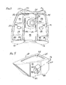
- FIGS. 1 to 3 show an example of a distal femoral implant component that may be used with the modular knee prosthesis system of the present invention.
- the distal femoral articulation component 10 has a pair of spaced, curved distal articulating surfaces 12, 14 extending posteriorly to a pair of spaced, curved posterior articulating surfaces 16, 18.
- the distal articulating surfaces 12, 14 extend anteriorly to anterior surfaces 20, 22, which are connected by a patellar groove 24.
- the distal femoral articulation component 10 has a plurality of flat bone-facing surfaces opposite the outer articulating surfaces 12, 14, 16, 18, 20, 22, 24.
- the bone-facing surfaces include flat distal bone-facing surfaces 26, 28, posterior bone-facing surfaces 30, 32, anterior bone-facing surfaces 34, 36 and sets of anterior chamfers 38, 40 and posterior chamfers 42, 44.
- the anterior chamfers 38, 40 connect the anterior bone-facing surfaces 34, 36 to the distal bone-facing surfaces 26, 28 and the posterior chamfers 42, 44 connect the distal bone-facing surfaces 26, 28 to the posterior bone-facing surfaces 30, 32.
- All of the bone-facing surfaces 26, 28, 30, 32, 34, 36, 38, 40, 42, 44 are fixation surfaces, and include recesses to receive bone-cement to bond the distal femoral articulation component 10 to the resected surfaces of the distal femur.
- the recesses define cement pockets (shown at 33, 35 and 37 in FIG. 1 and 31 and 33 in FIG. 3 ) that may have features such as those disclosed in US-A-2012/083894 .
- the cement pockets 33, 35 in the posterior bone-facing surfaces 30, 32 may be angled so that the pockets are deeper at their inferior ends than at their superior ends.
- the distal femoral articulation component 10 is a posterior stabilized component intended for use when the posterior cruciate ligament is sacrificed. Accordingly, the distal femoral articulation component 10 includes a box 46 having a box top wall 48 and box side walls 50, 52 extending from the box top wall 48 to the bone-facing surfaces 26, 28, 30, 32, 34, 36, 38, 40, 42, 44 of the distal femoral articulation component 10.
- the distal femoral articulation component 10 also includes a modular stem 54, along with a collar 56 for placement between the stem 54 and the box top wall 48 and a bolt (not shown) so that the stem 54 and collar 56 may be selectively mounted on the box 46 of the distal femoral articulation component 10.
- Each stem 54 may have a frusto-conical outer surface that is smooth and tapered for receiving a metaphyseal sleeve and connection structures at the proximal end for connecting a stem extension (not shown) to the stem 54.
- the distal femoral articulation component 10 has bores 57, 58, 59 to receive connectors to selectively assemble with a distal femoral augment 60 and a posterior femoral augment 62.
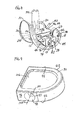
- the distal femoral augment 60 is shown in FIGS. 4 to 8 , and 15 and 16 , and is sized and shaped to be received on one of the distal bone-facing surfaces 26, 28 of the distal femoral articulation component 10.
- the posterior femoral augment 62 is in FIGS. 9 to 16 and is sized and shaped to be received on one of the posterior bone-facing surfaces 30, 32 of the distal femoral articulation component 10. Both augments 60, 62 are described in more detail below.
- the distal femoral augment 60 has a first surface 64, a second surface 66 spaced from and generally opposite to the first surface 64 and side surfaces 68, 70 extending between the first surface 64 and the second surface 66.
- the distal femoral augment 60 has a body extending between the surfaces 64, 66, 68, 70.
- One of the side surfaces 70 of the first distal femoral augment 60 has an oval-shaped opening 72 into a cylindrical bore 74.
- the bore 74 extends from the side surface 70, through the body of the augment 60 and out through the second surface 66 of the augment 60.
- the bore 74 has a central longitudinal axis 76 that defines an acute angle with both the first surface 64 and the second surface 66 of the augment 60.
- the interior of the cylindrical bore 74 is smooth, and sized to receive the shaft of a first connector 78.
- the first connector 78 comprises a screw or bolt, although other connectors, such as a pin and collet, could be used.
- the screw or bolt 78 may be used to secure the distal femoral augment 60 to the distal femoral articulation component 10 by placing the second surface 66 of the distal augment 60 against the distal bone-facing surface 26 or 28, as shown in FIGS. 8 , 15 and 16 .
- the screw 78 is inserted through the hole 72 and bore 74 along the axis 76 and the threaded end of the screw 78 is threaded into the opening 72 and threaded bore 74 and tightened to secure the elements 10, 60 together.
- the surgeon can accomplish all of these tasks from the medial or lateral side; it is not necessary to align a screw or screwdriver along a generally superior-inferior axis to connect the augment 60 to the distal femoral articulation component 10.
- the side of the augment 60 including the hole or opening 72 and bore 74 could be either the medial or lateral side of the augment.
- the distal augment 60 could be made symmetrical about an anterior-posterior plane with openings and bores provided on each side of a single augment, one on the medial side and one on the lateral side to define a universal distal augment.
- Such a universal distal augment could be selectively used on either the medial or lateral condyle of the distal femoral articulation component.
- the device shown in the drawings has a single hole and bore on one side of the distal augment, it should be understood that multiple holes and bore could be provided on one or more sides of the augment.
- one or more plugs could be provided to fill the used holes.
- FIGS. 20 and 21 Another distal augment is shown in FIGS. 20 and 21 , where elements similar to those described above are identified with the same reference numbers used in FIGS. 4 to 7 , followed by the designation "A".
- the device shown in FIGS. 20 and 21 differs from that of FIGS. 4 to 7 in that the cylindrical bore 74A extends from the side surface 70A, through the body of the augment 60A and out through the opposite side surface 68A of the augment 60A.
- the bore 74A has a central longitudinal axis 76A that lies between the first surface 64A and the second surface 66A of the augment 60A.
- the interior of the cylindrical bore 74A is smooth, and sized to receive the shaft of a connector.
- the side walls 50, 52 of the box 46 may have threaded bores (not shown), similar to bore 58 but sized, shaped and positioned to receive the connector to assemble the distal augment 60A and the distal femoral articulation component 10 together.
- the first and second surfaces 64, 64A, 66, 66A of the distal femoral augment 60, 60A may include additional features.
- the first surface 64, 64A which faces the resected bone surface may include a recess defining a cement pocket, referenced as 65 in FIGS. 4 , 5 , 7 , 8 , 15 and 16 , and as 65A in FIG. 20 .
- the second surface 66, 66A which faces the distal bone-facing surface 26 or 28 of the distal femoral articulation component 10 may include a plurality of raised feet to stabilize and locate the augment 60 on the distal femoral articulation component 10; such feet are shown in phantom at 80 in FIG. 7 .
- the outermost surfaces of the feet 80 are shaped to rest upon the surface of the cement pocket 65 in the distal bone-facing surface 26 or 28.
- Both side surfaces 68, 68A, 70, 70A of the augment 60, 60A may also include features to facilitate grasping the augment with a tool, such as recesses referenced as 82 in FIGS. 4 , 7 , 8 and 16 and as 82A in FIG. 21 .
- the anterior portion of the distal femoral augment 60, 60A is shaped to fit against the anterior chamfer surface 38 or 40 of the distal femoral articulation component 10.
- the anterior-posterior length of the distal femoral augment 60, 60A allows for a space between the posterior-most end of the augment 60, 60A and the posterior bone-facing surface 30 or 32 of the distal femoral articulation component 10 to allow for a part of the posterior femoral augment 62 to be received between the distal femoral augment 60, 60A and the posterior bone-facing surface 30 or 32.
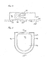
- the posterior femoral augment 62 has a first surface 90, a second surface 92 spaced from and generally opposite to the first surface 90 and side surfaces 94, 96 extending between the first surface 90 and the second surface 92.
- the posterior femoral augment 62 has a body extending between the surfaces 90, 92, 94, 96.
- One of the side surfaces 94 or 96 of the posterior femoral augment 62 has a circular opening 97 into a tapered counter-sink 98 and cylindrical bore 100.
- the bore 100 extends from one side surface to the other and has a central longitudinal axis 102 that runs between the first and second surfaces 90, 92.
- the interior of the cylindrical bore 100 is smooth, and sized to receive the shaft of a second connector 104.
- the second connector 104 comprises a screw or bolt having a length greater than the medial-lateral dimension of the posterior femoral augment 62 so that the screw may be inserted through the opening 97 and bore 100 to engage the threads in the bore 58 in the side wall 52 of the femoral box 46.
- the second connector 104 may be used to secure the posterior femoral augment 62 to the distal femoral articulation component 10 by placing the second surface 92 of the posterior augment 62 against the posterior bone-facing surface 30 or 32, as shown in FIGS. 14 to 16 .
- the second connector 104 is inserted through the hole 97 and bore 100 along the axis 102 and the threaded end of the second screw connector 104 is received into the opening and engages the threads of the bore 58 in the side wall 50 or 52 of the femoral box 46.
- the connector 104 is tightened to secure the elements 10, 62 together. The surgeon can accomplish all of these tasks from the medial or lateral side; it is not necessary to align a screw or screwdriver along a generally anterior-posterior axis to connect the posterior augment 62 to the distal femoral articulation component 10.
- the bore 100 could be oriented to extend from one of the side surfaces 94 or 96 to the posterior surface 92 and into a bore formed in one of the posterior bone facing surfaces 30 or 32, similar to the bore 74 in the distal femoral augment 60 discussed above.
- other types of connectors such as pins and collets could be used.
- the posterior augment shown in FIGS. 9 to 18 is asymmetrical about a superior-inferior plane, although the augment could be symmetrical.
- a symmetrical design is shown in FIG. 19 , with parts similar to those described above for the asymmetrical design labelled with the same reference number, followed by the designation "A".
- the symmetrical design, shown in FIG. 19 is substantially identical to the asymmetrical design, differing only in that both side surfaces 94A, 96A have the same size opening 97A, 99A leading into the bore 100A, and both ends of the bore 100A have tapered counter-sinks 98A, 101A. With the design of FIG.
- the same posterior augment 62A could be used on either the medial or lateral condyle of the distal femoral articulation component.
- multiple holes and bores could be provided on each side of the posterior augment. If multiple holes are provided, plugs may be provided to fill unused holes.
- Another posterior augment is shown in FIG. 22 , with parts similar to those described above for the above posterior augment designs 62, 62A labelled with the same reference number, followed by the designation "B".
- the bore 100B has a central longitudinal axis 102B and the counterbore or counter-sink 98B has a different central longitudinal axis 103 offset from the central longitudinal axis 102B of the bore 100B.
- the shaft of the screw or bolt may have a diameter smaller than the diameter of the bore 100B and the head of the bolt may have a diameter smaller than the diameter of the counterbore 98B so that the surgeon has more play in the position of the augment 62B when first assembling the components; as the bolt is tightened, the head of the screw or bolt will ultimately fit within the portion of the counterbore 98B immediately surrounding the bore 100B and the augment 62B will be held tightly against the posterior bone-facing surface 30 or 32 of the femoral articulation component.
- the first and second surfaces 90, 90A, 90B, 92. 92A, 92B of the posterior femoral augment 62, 62A, 62B may include additional features.
- the first surface 90, 90A, 90B which faces the resected bone surface may include a recess defining a cement pocket, shown at 106 in FIGS. 9 and 11 to 16 .
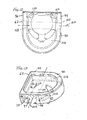
- the second surface 92, 92A, 92B which faces the posterior bone-facing surface 30 or 32 of the distal femoral articulation component 10 may include a plurality of raised feet to stabilize and locate the augment 62 on the distal femoral articulation component 10; such feet are shown at 110 in FIG. 10 , in phantom in FIGS. 12-13 , at 110A in FIG. 19 and at 110B in FIG. 22 .
- the outermost surfaces of the feet 110, 110A, 110B are shaped to rest upon the surface of the cement pocket 33 or 35 in the posterior bone-facing surface 30 or 32.
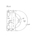
- the feet 110, 110A, 110B may be shaped so that the posterior-most surfaces of the feet lie in a plane 112 that defines an angle ⁇ with the plane 114 parallel to the plane 116 along the anterior-most portions of the first surface 90 of the posterior augment 62, as shown in FIG. 17 .
- the angle ⁇ may vary according to the corresponding taper angle in the cement pocket 35 or 37. It should be understood that if the cement pocket 33 or 35 in the distal femoral articulation component 10 is not tapered, planes 112, 114 and 116 may all be parallel to each other. It should also be understood that the same principles may be applied to the feet 80 of the distal augment 60.
- FIG. 17 also shows the cement pocket 106 in the first surface 90 of the posterior augment.
- the posterior-most surface of the cement pocket 106 lies in a plane 118.
- plane 118 is parallel to planes 114 and 116, although it should be understood that features of devices disclosed in US-A-2012/083894 might be applied to the cement pocket 106, with the plane 118 defining an acute angle with the planes 114, 116.
- the same angular relationships may be used for cement pocket 65 in the distal augment 60.
- FIGS. 18 and 19 show a plurality of feet 110 shaped and positioned to fit in a unique position within the cement pocket to locate the posterior augment 62 positively within the cement pocket (an example of the outline of the cement pocket being shown in phantom at 35) of the distal femoral articulation component 10.
- the feet 80 of the distal augment 60 may be shaped and positioned to fit in a unique position to positively locate the distal augment 60 within the distal cement pockets 31, 33.
- a typical surgical kit would include a variety of sizes of distal femoral augments 60, 60A and posterior femoral augments 62, 62A, 62B to provide the surgeon with a choice among various thicknesses of augments.
- both types of augments could be provided with thicknesses increasing by 2 mm for each size of augment.
- distal femoral articulation components are commonly provided in a variety of sizes, a group of augments of different thicknesses may be provided for use with each size of distal femoral articulation component in the kit.
- the augments 60, 60A, 62, 62A, 62B may be used with the distal femoral articulation component 10 to address bony deficiencies and in situations where placing the articulation component 10 directly on the resected bone would result in an undesirable position of the articulation surfaces 12, 14; that is, the joint line defined by the articulation between the femoral articulation surfaces 12, 14 and the articulation surfaces of the proximal tibial component may be elevated.
- Elevation of the joint line may adversely affect performance of the prosthetic knee system: the positions of the collateral ligament attachments to the femur relative to the joint line may impact knee kinematics, the articulation of the patella against the femoral component will be impacted, and the function of the extensor mechanism will also be impacted.
- the surgeon may opt to use the distal augments of the present invention along with the posterior augments to property position the femoral articulation surfaces in both extension and flexion.
- Various combinations of thicknesses of distal and femoral augments 60, 60A, 62, 62A, 62B may be used to optimize the assembly for the needs of the individual patient.
- the distal augment 60, 60A may be assembled with the distal femoral articulation component 10 intraoperatively, by inserting a connector 78 through the bore 74, 74A along axis 76, 76A in the distal femoral augment 60, 60A and into the opening 57 or 59 in the distal bone-facing surface 26 or 28 of the distal femoral articulation component 10.
- connector 104 may be inserted through the bore 100, 100A, 100B in the posterior femoral augment 62, 62A, 62B and into opening 58 (or the equivalent opening on the opposite side of the femoral box 46) in the femoral box 46 of the distal femoral articulation component 10.
- the location and orientation of the openings 57, 58, 59, 72, 72A, 97, 97A, 97B and bores 74, 74A, 100, 100A, 100B allow for the components 10, 60, 60A, 62, 62A, 62B to be assembled with standard tools.
- the assembly may then be cemented into place on the distal femur by placing an appropriate cement in the cement pockets 65, 65A, 106 of the augments 60, 60A, 62, 62A, 62B.
- the connectors 78, 104 remain accessible from either the medial or lateral side after implantation.
- the connectors 78, 104 remain accessible post-implantation, revision of the distal femoral implant is facilitated.
- the surgeon may use a standard tool to remove the connectors 78, 104 from either the medial or lateral side while the assembly remains on the femur to sever the connections between the augments 60, 60A, 62, 62A, 62B and the distal femoral articulation component 10.
- the distal femoral articulation component 10 may be readily removed (following separation of the anterior bone-facing surfaces 34, 36 of the distal femoral articulation component 10 from the adjacent bone surface, such as by running a saw blade through the cement mantle along the anterior bone-facing surfaces 34, 36).
- the surgeon may then readily cut through the cement mantle between the augments 60, 62 and the bone to remove the augments 60, 60A, 62, 62A, 62B from the bone.
- All of the components of the implant system may be made of standard materials, such as standard metals (such as titanium alloys and cobalt-chromium alloys) for the augments 60, 60A, 62, 62A, 62B and distal femoral articulating component 10.
- standard metals such as titanium alloys and cobalt-chromium alloys
Landscapes
- Health & Medical Sciences (AREA)
- Orthopedic Medicine & Surgery (AREA)
- Cardiology (AREA)
- Oral & Maxillofacial Surgery (AREA)
- Transplantation (AREA)
- Engineering & Computer Science (AREA)
- Biomedical Technology (AREA)
- Heart & Thoracic Surgery (AREA)
- Vascular Medicine (AREA)
- Life Sciences & Earth Sciences (AREA)
- Animal Behavior & Ethology (AREA)
- General Health & Medical Sciences (AREA)
- Public Health (AREA)
- Veterinary Medicine (AREA)
- Physical Education & Sports Medicine (AREA)
- Prostheses (AREA)
Abstract
Description
- The present invention relates to prosthetic joints, and more particularly to a modular prosthetic knee joint system that includes augments.
- The knee joint basically consists of the bone interface of the distal end of the femur and the proximal end of the tibia. The patella appears to cover or at least partially protect this interface. The patella is a sesamoid bone within the tendon of the long muscle (quadriceps) on the front of the thigh. This tendon inserts into the tibial tuberosity and the posterior surface of the patella is smooth and glides over the femur.
- The femur is configured with two knob like processes (the medial condyle and the lateral condyle) which are substantially smooth and which articulate with the medial plateau and the lateral plateau of the tibia, respectively. The plateaus of the tibia are substantially smooth and slightly cupped thereby providing a slight receptacle for receipt of the femoral condyles.
- When the knee joint is damaged whether as a result of an accident or illness, a prosthetic replacement of the damaged joint may be necessary to relieve pain and to restore normal use to the joint. Typically the entire knee joint is replaced by means of a surgical procedure that involves removal of the surfaces of the corresponding damaged bones and replacement of these surfaces with prosthetic implants. This replacement of a native joint with a prosthetic joint is referred to as a primary total-knee arthroplasty.
- On occasion, the primary knee prostheses fails. Failure can result from many causes, including wear, aseptic loosening, osteolysis, ligamentous instability, arthrofibrosis and patellofemoral complications. When the failure is debilitating, revision knee surgery may be necessary. In a revision, the primary knee prosthesis is removed and replaced with components of a revision prosthetic knee system.
- Knee implant systems for both primary and revision applications are available from a variety of manufacturers, including DePuy Orthopaedics Inc of Warsaw, Indiana, USA. DePuy and others offer several different systems for both primary and revision applications. For example, DePuy Orthopaedics market knee systems under the trade marks PFC SIGMA, LCS and S-ROM. Each of these orthopaedic knee systems includes several components, some appropriate for use in primary knee arthroplasty and some appropriate for use in revision surgery.
- DePuy Orthopaedics also offers other orthopaedic implant systems for other applications. One such system is marketed under the trade mark LPS. The LPS system is provided for use in cases of severe trauma and disease. In such cases, the trauma or disease can lead to significant amounts of bone loss. The LPS system provides components that can replace all or significant portions of a particular bone, such as the femur. Details of the DePuy LPS system are disclosed in
US-A-2003/0204267 . - In some patients, bone deficiencies in the distal and posterior femur may make it difficult for the surgeon to re-establish the natural joint line and to provide equal flexion and extension gaps. Prosthetic knee implant systems have commonly included femoral augments for use on the distal and posterior bone-facing surfaces of the femoral implant components. Examples of such augments are disclosed in
US-5984969 andUS-6005018 . Such components serve to augment the inferior and posterior portions of the femoral component to add additional thickness to compensate for the lack of sufficient boney tissue, allowing the joint line to be distalized. - As disclosed in
US-5984969 andUS-6005018 , such augments are commonly connected to the bone-facing surfaces of the distal femoral articulation components through screws or pins inserted superiorly or anteriorly from the bone-facing surfaces of the augments and threaded into threaded openings or collets or other receptacles received in openings in the bone-facing surface of the distal femoral articulation components. For the posterior augments, a special tool may be required to connect the augment to the posterior condylar bone-facing surface of the distal femoral articulation component; for example, a wobble driver tip to facilitate access across the femoral anterior flange. - After the augmented distal femoral articulation component is implanted, the augments and distal femoral articulation components cannot be disassembled until after the entire assembly is removed from the distal femur because the connection mechanisms are no longer accessible. During revision surgery, it may be advantageous to the surgeon to have the option of severing the connections between the distal femoral articulation component and the augments prior to removal of these components from the bone.
- The present invention provides a modular knee implant system that allows the surgeon to separate distal femoral articulation components and augments from an implanted assembly prior to removal of the assembly from the bone. The modular knee implant system of the present invention also allows for quick and simple connection of augments to distal femoral articulation components.
- The invention provides a modular knee prosthesis system which includes a distal femoral articulation component, an augment and a first connector for securing the augment to the distal femoral articulation component. The distal femoral articulation component has a pair of curved distal condylar articulating surfaces, a pair of curved posterior condylar articulating surfaces, a distal bone-facing surface and a posterior bone-facing surface. The augment is sized and shaped to be received on one of the bone-facing surfaces of the distal femoral articulation component. The augment includes a first surface, a second surface spaced from and generally opposite to the first surface, side surfaces extending between and connecting the first surface and the second surface, and a body between the first and second surface. At least one of the side surfaces has an opening into a bore extending from the side surface through the body and through another surface of the augment. The distal femoral articulation component has an opening to receive the connector to selectively mount the augment to the distal femoral articulation component.
- Optionally, the bore of the augment has a central longitudinal axis that defines an acute angle with at least one of the first surface and the second surface of the augment.
- Optionally, the augment is a distal femoral augment, the central longitudinal axis of the bore defines an acute angle with the second surface of the augment and the opening in the distal femoral articulation component is in the distal bone-facing surface of the distal femoral articulation component. The side surfaces of the augment may then include a medial surface and a lateral surface and the opening into the bore may be in one of the medial surface and lateral surface.
- Optionally, the bore in the augment has a central longitudinal axis between the first surface and the second surface of the augment.
- Optionally, the augment is a posterior femoral augment. The side surfaces of the augment may then include a medial surface and a lateral surface and the opening into the bore may be in one of the medial surface and lateral surface. The distal femoral articulation component may then be a posterior stabilized component including a box having a box top wall and a box side wall; the box side wall extends from the box top wall to at least one of the distal bone-facing surface and a posterior bone-facing surface and the opening in the distal femoral articulation component is in the box side wall.
- Optionally, the connecting element may comprise a screw or bolt.
- Optionally, the distal bone-facing surface of the distal femoral articulation component may have a recessed distal cement pocket and the posterior bone-facing surface of the distal femoral articulation component may have a recessed posterior cement pocket. The second surface of the augment may include a plurality of protruding feet sized, shaped and positioned to be received in a unique position within one of the cement pockets when the augment is assembled with the distal femoral articulation component to locate the augment positively with respect to the cement pocket. Optionally, the recessed cement pocket may be tapered so that the pocket is deeper at one end and the feet of the augment may be shaped so that the outermost surfaces of the feet lie in a plane that defines an acute angle with the first surface of the augment.
- Optionally, the first surface of the augment may have a recessed cement pocket.
- The invention also provides a modular knee prosthesis system which comprises a distal femoral articulation component, a distal augment, a posterior augment and a first connector for securing at least one of the augments to the distal femoral articulation component through the bore of the augment and the opening in the distal femoral articulation component. The distal femoral articulation component has a pair of curved distal condylar articulating surfaces, a pair of curved posterior condylar articulating surfaces, a distal bone-facing surface, a posterior bone-facing surface and an opening. The distal augment is sized and shaped to be received on the distal bone-facing surface of the distal femoral articulation component and includes a first surface, a second surface spaced from and generally opposite to the first surface and side surfaces extending between and connecting the first surface and the second surface. The distal augment has a body between the first and second surface and at least one of the side surfaces has an opening into a bore extending from the side surface through the body and through another surface of the distal augment. The posterior augment is sized and shaped to be received on the posterior bone-facing surface of the distal femoral articulation component and includes a first surface, a second surface spaced from and generally opposite to the first surface and side surfaces extending between and connecting the first surface and the second surface. The posterior augment has a body between the first and second surfaces and at least one of the side surfaces has an opening into a bore extending from the side surface through the body and through another surface of the posterior augment.
- Optionally, the distal femoral articulation component is a posterior stabilized component including a box having a box top wall and a box side wall, the box side wall extending from the box top wall to at least one of the distal bone-facing surface and a posterior bone-facing surface of the distal femoral articulation component. The opening in the distal femoral articulation component may then be in the box side wall. Furthermore, the bore in at least one of the augments may have a central longitudinal axis between the first surface and the second surface of the posterior augment. Furthermore, the opening in the box side wall may be positioned and shaped to align with the bore in the augment when the second surface of the augment is mounted on one of the bone-facing surfaces of the distal femoral articulation component. The bore in at least one of the augments may have a central longitudinal axis defining an acute angle with the second surface of that augment. At least one of the bone-facing surfaces of the distal femoral articulation component may have an opening into a bore. This opening may be positioned and shaped to align with the bore in the augment when the second surface of the augment is mounted on one of the bone-facing surfaces of the distal femoral articulation component. The bore in one of the augments may then extend between the side surfaces of the augment and the bore in the other augment may extend from the side surface of the augment to the second surface of the augment. The system may include a second connector that is longer than the first connector.
- Optionally, the distal bone-facing surface of the distal femoral articulation component may have a recessed distal cement pocket and the posterior bone-facing surface of the distal femoral articulation component may have a recessed posterior cement pocket. The second surface of the distal augment may include a plurality of protruding feet sized, shaped and positioned to be received in a unique position within the distal cement pocket when the distal augment is assembled with the distal femoral articulation component to positively locate the distal augment with respect to the distal cement pocket. The second surface of the posterior augment may also include a plurality of protruding feet sized, shaped and positioned to be received in a unique position within the posterior cement pocket when the posterior augment is assembled with the distal femoral articulation component to positively locate the posterior augment with respect to the posterior cement pocket. In this construction, the recessed posterior cement pocket may tapered so that the posterior cement pocket is deeper at one end and the feet of the posterior augment may be shaped so that the outermost surfaces of the feet lie in a plane that defines an acute angle with the first surface of the posterior augment.
- Optionally, the first surface of the distal augment may have a recessed cement pocket and the first surface of the posterior augment may have a recessed cement pocket.
- Optionally, the opening in the distal femoral articulation component is in the distal bone-facing surface of the distal femoral articulation component, and the opening in the distal bone-facing surface and the bore in the of the distal femoral articulation component are positioned and shaped to align with the bore in the distal augment when the second surface of the distal augment is mounted on the distal bone-facing surface of the distal femoral articulation component.
- Optionally, the distal femoral articulation component is a posterior stabilized component including a box having a box top wall and a box side wall, the box side wall extending from the box top wall to at least one of the distal bone-facing surface and a posterior bone-facing surface of the distal femoral articulation component, in which the opening in the distal femoral articulation component is in the box side wall.
- Optionally, the bore in at least one of the augments has a central longitudinal axis between the first surface and the second surface of the posterior augment.
- Optionally, the opening in the box side wall is positioned and shaped to align with the bore in the augment when the second surface of the augment is mounted on one of the bone-facing surfaces of the distal femoral articulation component.
- Optionally, the bore in at least one of the augments has a central longitudinal axis defining an acute angle with the second surface of that augment.
- Optionally, at least one of the bone-facing surfaces of the distal femoral articulation component has an opening into a bore, and the opening in the bone-facing surface is positioned and shaped to align with the bore in the augment when the second surface of the augment is mounted on one of the bone-facing surfaces of the distal femoral articulation component.
- Optionally, the bore in one of the augments extends between side surfaces of the augment and the bore in the other augment extends from the side surface of the augment to the second surface of the augment.
- Optionally, the modular knee prosthesis system includes a second connector that is longer than the first connector.
- Optionally, the distal bone-facing surface of the distal femoral articulation component has a recessed distal cement pocket, the posterior bone-facing surface of the distal femoral articulation component has a recessed posterior cement pocket, the second surface of the distal augment includes a plurality of protruding feet sized, shaped and positioned to be received in a unique position within the distal cement pocket when the distal augment is assembled with the distal femoral articulation component to positively locate the distal augment with respect to the distal cement pocket, and the second surface of the posterior augment includes a plurality of protruding feet sized, shaped and positioned to be received in a unique position within the posterior cement pocket when the posterior augment is assembled with the distal femoral articulation component to positively locate the posterior augment with respect to the posterior cement pocket.
- Optionally, the recessed posterior cement pocket is tapered so that the posterior cement pocket is deeper at one end, and the feet of the posterior augment are shaped so that the outermost surfaces of the feet lie in a plane that defines an acute angle with the first surface of the posterior augment.
- Optionally, the first surface of the distal augment has a recessed cement pocket, and the first surface of the posterior augment has a recessed cement pocket.
- The invention is described below by way of example with reference to the accompanying drawings, in which:
-
FIG. 1 is a perspective view of a distal femoral articulation component of a modular knee prosthesis system. -
FIG. 2 is a side view of the distal femoral articulation component ofFIG. 1 . -
FIG. 3 is a top view of the distal femoral articulation component ofFIGS. 1 and 2 . -
FIG. 4 is a perspective view of a distal augment of a modular knee prosthesis. -
FIG. 5 is a top view of the distal augment ofFIG. 4 . -
FIG. 6 is a side view of the distal augment ofFIGS. 4 and5 . -
FIG. 7 is a perspective of the distal augment ofFIGS. 4 to 6 , with additional features shown in phantom. -
FIG. 8 is a perspective view showing the distal femoral articulation component ofFIGS. 1 to 3 with the distal augment ofFIGS. 4 to 7 shown in place on the distal bone-facing surface of the distal femoral articulation component and also showing a connector for securing the distal augment to the distal femoral articulation component. -
FIG. 9 is a perspective view of a posterior augment of a modular knee prosthesis system. -
FIG. 10 is a side view of the posterior augment ofFIG. 9 . -
FIG. 11 is a top view of the posterior augment ofFIGS. 9 and10 . -
FIG. 12 is a top view of the posterior augment ofFIGS. 9 to 11 , with additional features shown in phantom. -
FIG. 13 is a perspective view of the posterior augment ofFIGS. 9 to 12 , with additional features shown in phantom. -
FIG. 14 is a perspective view showing the distal femoral articulation component ofFIGS. 1 to 3 with the posterior augment ofFIGS. 9 to 13 shown in place on the posterior bone-facing surface of the distal femoral articulation component and also showing a connector for securing the posterior augment to the distal femoral articulation component. -
FIG. 15 is a top view showing the distal femoral articulation component ofFIGS. 1 to 3 with the distal augment ofFIGS. 4 to 7 and posterior augment ofFIGS. 9 to 13 shown in place on the distal and posterior bone-facing surfaces of the distal femoral articulation component and also showing connectors for securing the distal and posterior augments to the distal femoral articulation component. -
FIG. 16 is a perspective view of the components ofFIG. 15 . -
FIG. 17 is a cross-section of the posterior augment ofFIGS. 9 to 13 taken along line 17-17 ofFIG. 11 . -
FIG. 18 is a bottom plan view of the posterior augment ofFIGS. 9 to 13 and17 , with the outline of the posterior cement pocket of the distal femoral articulation component shown in phantom. -
FIG. 19 is a view similar toFIG. 18 , showing another posterior augment that is universal, that is, that can be selectively used on either the medial or lateral side of the distal femoral articulation component. -
FIG. 20 is a top view of another distal augment. -
FIG. 21 is a side view of the distal augment ofFIG. 20 . -
FIG. 22 is a side view of the posterior augment, similar toFIG. 9 but incorporating an additional feature. - Terms representing anatomical references, such as anterior, posterior, superior, inferior, proximal and distal are used in this document in reference to the orthopaedic implants described herein as well as in reference to the patient's natural anatomy. Such terms have well-understood meanings in both the study of anatomy and the field of orthopaedics. Use of such anatomical reference terms in this document is intended to be consistent with their well-understood meanings unless noted otherwise.
-
FIGS. 1 to 3 show an example of a distal femoral implant component that may be used with the modular knee prosthesis system of the present invention. The distalfemoral articulation component 10 has a pair of spaced, curved distal articulatingsurfaces posterior articulating surfaces surfaces anterior surfaces patellar groove 24. - The distal
femoral articulation component 10 has a plurality of flat bone-facing surfaces opposite the outer articulatingsurfaces surfaces surfaces surfaces anterior chamfers posterior chamfers surfaces surfaces surfaces surfaces surfaces femoral articulation component 10 to the resected surfaces of the distal femur. The recesses define cement pockets (shown at 33, 35 and 37 inFIG. 1 and 31 and 33 inFIG. 3 ) that may have features such as those disclosed inUS-A-2012/083894 . For example, the cement pockets 33, 35 in the posterior bone-facingsurfaces - The distal
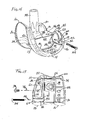
femoral articulation component 10 is a posterior stabilized component intended for use when the posterior cruciate ligament is sacrificed. Accordingly, the distalfemoral articulation component 10 includes abox 46 having a boxtop wall 48 andbox side walls top wall 48 to the bone-facingsurfaces femoral articulation component 10. - The distal
femoral articulation component 10 also includes amodular stem 54, along with acollar 56 for placement between thestem 54 and the boxtop wall 48 and a bolt (not shown) so that thestem 54 andcollar 56 may be selectively mounted on thebox 46 of the distalfemoral articulation component 10. Each stem 54 may have a frusto-conical outer surface that is smooth and tapered for receiving a metaphyseal sleeve and connection structures at the proximal end for connecting a stem extension (not shown) to thestem 54. - The distal
femoral articulation component 10 hasbores FIGS. 4 to 8 , and15 and 16 , and is sized and shaped to be received on one of the distal bone-facingsurfaces femoral articulation component 10. The posterior femoral augment 62 is inFIGS. 9 to 16 and is sized and shaped to be received on one of the posterior bone-facingsurfaces femoral articulation component 10. Both augments 60, 62 are described in more detail below. - The distal femoral augment 60 has a
first surface 64, asecond surface 66 spaced from and generally opposite to thefirst surface 64 and side surfaces 68, 70 extending between thefirst surface 64 and thesecond surface 66. The distal femoral augment 60 has a body extending between thesurfaces - One of the side surfaces 70 of the first distal femoral augment 60 has an oval-shaped
opening 72 into acylindrical bore 74. Thebore 74 extends from theside surface 70, through the body of the augment 60 and out through thesecond surface 66 of the augment 60. Thebore 74 has a centrallongitudinal axis 76 that defines an acute angle with both thefirst surface 64 and thesecond surface 66 of the augment 60. The interior of thecylindrical bore 74 is smooth, and sized to receive the shaft of afirst connector 78. In the device shown in the drawings, thefirst connector 78 comprises a screw or bolt, although other connectors, such as a pin and collet, could be used. - The screw or bolt 78 may be used to secure the distal femoral augment 60 to the distal
femoral articulation component 10 by placing thesecond surface 66 of the distal augment 60 against the distal bone-facingsurface FIGS. 8 ,15 and16 . Thescrew 78 is inserted through thehole 72 and bore 74 along theaxis 76 and the threaded end of thescrew 78 is threaded into theopening 72 and threaded bore 74 and tightened to secure theelements femoral articulation component 10. - The side of the augment 60 including the hole or
opening 72 and bore 74 could be either the medial or lateral side of the augment. Moreover, the distal augment 60 could be made symmetrical about an anterior-posterior plane with openings and bores provided on each side of a single augment, one on the medial side and one on the lateral side to define a universal distal augment. Such a universal distal augment could be selectively used on either the medial or lateral condyle of the distal femoral articulation component. In addition, although the device shown in the drawings has a single hole and bore on one side of the distal augment, it should be understood that multiple holes and bore could be provided on one or more sides of the augment. Moreover, in the case of holes and bores being provided on more than one side of the augment, or multiple holes and bores provided on the augment, one or more plugs could be provided to fill the used holes. - Another distal augment is shown in
FIGS. 20 and 21 , where elements similar to those described above are identified with the same reference numbers used inFIGS. 4 to 7 , followed by the designation "A". The device shown inFIGS. 20 and 21 differs from that ofFIGS. 4 to 7 in that the cylindrical bore 74A extends from theside surface 70A, through the body of the augment 60A and out through theopposite side surface 68A of the augment 60A. The bore 74A has a centrallongitudinal axis 76A that lies between thefirst surface 64A and thesecond surface 66A of the augment 60A. The interior of the cylindrical bore 74A is smooth, and sized to receive the shaft of a connector. Theside walls box 46 may have threaded bores (not shown), similar to bore 58 but sized, shaped and positioned to receive the connector to assemble the distal augment 60A and the distalfemoral articulation component 10 together. - The first and
second surfaces first surface FIGS. 4 ,5 ,7 ,8 ,15 and16 , and as 65A inFIG. 20 . Thesecond surface surface femoral articulation component 10, may include a plurality of raised feet to stabilize and locate the augment 60 on the distalfemoral articulation component 10; such feet are shown in phantom at 80 inFIG. 7 . The outermost surfaces of thefeet 80 are shaped to rest upon the surface of thecement pocket 65 in the distal bone-facingsurface - Both side surfaces 68, 68A, 70, 70A of the augment 60, 60A may also include features to facilitate grasping the augment with a tool, such as recesses referenced as 82 in
FIGS. 4 ,7 ,8 and16 and as 82A inFIG. 21 . - The anterior portion of the distal femoral augment 60, 60A is shaped to fit against the
anterior chamfer surface femoral articulation component 10. The anterior-posterior length of the distal femoral augment 60, 60A allows for a space between the posterior-most end of the augment 60, 60A and the posterior bone-facingsurface femoral articulation component 10 to allow for a part of the posterior femoral augment 62 to be received between the distal femoral augment 60, 60A and the posterior bone-facingsurface - The posterior femoral augment 62 has a
first surface 90, asecond surface 92 spaced from and generally opposite to thefirst surface 90 and side surfaces 94, 96 extending between thefirst surface 90 and thesecond surface 92. The posterior femoral augment 62 has a body extending between thesurfaces - One of the side surfaces 94 or 96 of the posterior femoral augment 62 has a
circular opening 97 into atapered counter-sink 98 andcylindrical bore 100. Thebore 100 extends from one side surface to the other and has a centrallongitudinal axis 102 that runs between the first andsecond surfaces cylindrical bore 100 is smooth, and sized to receive the shaft of asecond connector 104. In the device shown in the drawings, thesecond connector 104 comprises a screw or bolt having a length greater than the medial-lateral dimension of the posterior femoral augment 62 so that the screw may be inserted through theopening 97 and bore 100 to engage the threads in thebore 58 in theside wall 52 of thefemoral box 46. - The
second connector 104 may be used to secure the posterior femoral augment 62 to the distalfemoral articulation component 10 by placing thesecond surface 92 of the posterior augment 62 against the posterior bone-facingsurface FIGS. 14 to 16 . Thesecond connector 104 is inserted through thehole 97 and bore 100 along theaxis 102 and the threaded end of thesecond screw connector 104 is received into the opening and engages the threads of thebore 58 in theside wall femoral box 46. Theconnector 104 is tightened to secure theelements femoral articulation component 10. - Alternatively, the
bore 100 could be oriented to extend from one of the side surfaces 94 or 96 to theposterior surface 92 and into a bore formed in one of the posteriorbone facing surfaces bore 74 in the distal femoral augment 60 discussed above. In addition, other types of connectors (such as pins and collets) could be used. - The posterior augment shown in
FIGS. 9 to 18 is asymmetrical about a superior-inferior plane, although the augment could be symmetrical. A symmetrical design is shown inFIG. 19 , with parts similar to those described above for the asymmetrical design labelled with the same reference number, followed by the designation "A". The symmetrical design, shown inFIG. 19 , is substantially identical to the asymmetrical design, differing only in that both side surfaces 94A, 96A have thesame size opening 97A, 99A leading into thebore 100A, and both ends of thebore 100A have tapered counter-sinks 98A, 101A. With the design ofFIG. 19 , the same posterior augment 62A could be used on either the medial or lateral condyle of the distal femoral articulation component. In addition, multiple holes and bores could be provided on each side of the posterior augment. If multiple holes are provided, plugs may be provided to fill unused holes. Another posterior augment is shown inFIG. 22 , with parts similar to those described above for the above posterior augmentdesigns FIG. 22 , thebore 100B has a central longitudinal axis 102B and the counterbore or counter-sink 98B has a different centrallongitudinal axis 103 offset from the central longitudinal axis 102B of thebore 100B. With this device, the shaft of the screw or bolt may have a diameter smaller than the diameter of thebore 100B and the head of the bolt may have a diameter smaller than the diameter of the counterbore 98B so that the surgeon has more play in the position of the augment 62B when first assembling the components; as the bolt is tightened, the head of the screw or bolt will ultimately fit within the portion of the counterbore 98B immediately surrounding thebore 100B and the augment 62B will be held tightly against the posterior bone-facingsurface - The first and
second surfaces first surface 90, 90A, 90B which faces the resected bone surface, may include a recess defining a cement pocket, shown at 106 inFIGS. 9 and11 to 16 . Thesecond surface surface femoral articulation component 10, may include a plurality of raised feet to stabilize and locate the augment 62 on the distalfemoral articulation component 10; such feet are shown at 110 inFIG. 10 , in phantom inFIGS. 12-13 , at 110A inFIG. 19 and at 110B inFIG. 22 . The outermost surfaces of thefeet cement pocket surface - If the
cement pocket feet plane 112 that defines an angle θ with theplane 114 parallel to the plane 116 along the anterior-most portions of thefirst surface 90 of the posterior augment 62, as shown inFIG. 17 . The angle θ may vary according to the corresponding taper angle in thecement pocket cement pocket femoral articulation component 10 is not tapered,planes feet 80 of the distal augment 60. -
FIG. 17 also shows thecement pocket 106 in thefirst surface 90 of the posterior augment. InFIG. 17 , the posterior-most surface of thecement pocket 106 lies in a plane 118. In the device shown in the drawings, plane 118 is parallel toplanes 114 and 116, although it should be understood that features of devices disclosed inUS-A-2012/083894 might be applied to thecement pocket 106, with the plane 118 defining an acute angle with theplanes 114, 116. Although not shown, the same angular relationships may be used forcement pocket 65 in the distal augment 60. - Although locating feet, such as
feet surfaces FIGS. 18 and19 show a plurality offeet 110 shaped and positioned to fit in a unique position within the cement pocket to locate the posterior augment 62 positively within the cement pocket (an example of the outline of the cement pocket being shown in phantom at 35) of the distalfemoral articulation component 10. Although not shown, it should be understood that thefeet 80 of the distal augment 60 may be shaped and positioned to fit in a unique position to positively locate the distal augment 60 within the distal cement pockets 31, 33. - A typical surgical kit would include a variety of sizes of distal femoral augments 60, 60A and posterior femoral augments 62, 62A, 62B to provide the surgeon with a choice among various thicknesses of augments. For example, both types of augments could be provided with thicknesses increasing by 2 mm for each size of augment. Since distal femoral articulation components are commonly provided in a variety of sizes, a group of augments of different thicknesses may be provided for use with each size of distal femoral articulation component in the kit.
- In use, the
augments femoral articulation component 10 to address bony deficiencies and in situations where placing thearticulation component 10 directly on the resected bone would result in an undesirable position of the articulation surfaces 12, 14; that is, the joint line defined by the articulation between the femoral articulation surfaces 12, 14 and the articulation surfaces of the proximal tibial component may be elevated. Elevation of the joint line may adversely affect performance of the prosthetic knee system: the positions of the collateral ligament attachments to the femur relative to the joint line may impact knee kinematics, the articulation of the patella against the femoral component will be impacted, and the function of the extensor mechanism will also be impacted. To distalize the joint line and to compensate for inadequate bone at the distal femur, the surgeon may opt to use the distal augments of the present invention along with the posterior augments to property position the femoral articulation surfaces in both extension and flexion. Various combinations of thicknesses of distal andfemoral augments - The distal augment 60, 60A, may be assembled with the distal
femoral articulation component 10 intraoperatively, by inserting aconnector 78 through thebore 74, 74A alongaxis opening surface femoral articulation component 10. Similarly,connector 104 may be inserted through thebore femoral box 46 of the distalfemoral articulation component 10. The location and orientation of theopenings components augments connectors - Since the
connectors connectors augments femoral articulation component 10. Once these connections are severed, the distalfemoral articulation component 10 may be readily removed (following separation of the anterior bone-facingsurfaces femoral articulation component 10 from the adjacent bone surface, such as by running a saw blade through the cement mantle along the anterior bone-facingsurfaces 34, 36). The surgeon may then readily cut through the cement mantle between theaugments augments - All of the components of the implant system may be made of standard materials, such as standard metals (such as titanium alloys and cobalt-chromium alloys) for the
augments femoral articulating component 10.
Claims (15)
- A modular knee prosthesis system comprising:a distal femoral articulation component having a pair of curved distal condylar articulating surfaces, a pair of curved posterior condylar articulating surfaces, a distal bone-facing surface and a posterior bone-facing surface,an augment sized and shaped to be received on one of the bone-facing surfaces of the distal femoral articulation component, the augment including a first surface, a second surface spaced from and generally opposite to the first surface and side surfaces extending between and connecting the first surface and the second surface, a body between the first and second surface, at least one of the side surfaces having an opening into a bore extending from the side surface through the body and through another surface of the augment, anda first connector for securing the augment to the distal femoral articulation component,in which the distal femoral articulation component has an opening to receive the connector to selectively mount the augment to the distal femoral articulation component.
- The system of claim 1 in which the bore of the augment has a central longitudinal axis defining an acute angle with at least one of the first surface and the second surface.
- The system of claim 2 in which the augment is a distal femoral augment, the central longitudinal axis of the bore defines an acute angle with the second surface of the augment and the opening in the distal femoral articulation component is in the distal bone-facing surface of the distal femoral articulation component.
- The system of claim 3 in which the side surfaces of the augment include a medial surface and a lateral surface and the opening into the bore is in one of the medial surface and lateral surface.
- The system of claim 1 in which the bore in the augment has a central longitudinal axis between the first surface and the second surface.
- The system of claim 5 in which the augment is a posterior femoral augment.
- The system of claim 6 in which the side surfaces of the augment include a medial surface and a lateral surface and the opening into the bore is in one of the medial surface and lateral surface.
- The system of claim 7 in which the distal femoral articulation component is a posterior stabilized component including a box having a box top wall and a box side wall, the box side wall extending from the box top wall to at least one of the distal bone-facing surface and a posterior bone-facing surface, and in which the opening in the distal femoral articulation component is in the box side wall.
- The system of claim 1 in which the connecting element comprises a screw.
- The system of claim 1 in which:the distal bone-facing surface of the distal femoral articulation component has a recessed distal cement pocket,the posterior bone-facing surface of the distal femoral articulation component has a recessed posterior cement pocket, andthe second surface of the augment includes a plurality of protruding feet sized, shaped and positioned to be received in a unique position within one of the cement pockets when the augment is assembled with the distal femoral articulation component to positively locate the augment with respect to the cement pocket.
- The system of claim 10 in which the recessed cement pocket is tapered so that the pocket is deeper at one end, and the feet of the augment are shaped so that the outermost surfaces of the feet lie in a plane that defines an acute angle with the first surface of the augment.
- The system of claim 1 in which the first surface of the augment has a recessed cement pocket.
- A modular knee prosthesis system comprising:a distal femoral articulation component having a pair of curved distal condylar articulating surfaces, a pair of curved posterior condylar articulating surfaces, a distal bone-facing surface, a posterior bone-facing surface and an opening,a distal augment sized and shaped to be received on the distal bone-facing surface of the distal femoral articulation component, the distal augment including a first surface, a second surface spaced from and generally opposite to the first surface and side surfaces extending between and connecting the first surface and the second surface, a body between the first and second surface, at least one of the side surfaces having an opening into a bore extending from the side surface through the body and through another surface of the distal augment,a posterior augment sized and shaped to be received on the posterior bone-facing surface of the distal femoral articulation component, the posterior augment including a first surface, a second surface spaced from and generally opposite to the first surface and side surfaces extending between and connecting the first surface and the second surface, a body between the first and second surface, at least one of the side surfaces having an opening into a bore extending from the side surface through the body and through another surface of the posterior augment, anda first connector for securing at least one of the augments to the distal femoral articulation component through the bore of the augment and the opening in the distal femoral articulation component.
- The system of claim 13 in which the bore in the distal augment extends from one side surface to the second surface, and the bore in the posterior augment extends from one side surface to another side surface.
- The system of claim 14 in which the bore in the distal augment has a central longitudinal axis defining an acute angle with the second surface.
Applications Claiming Priority (1)
| Application Number | Priority Date | Filing Date | Title |
|---|---|---|---|
| US13/539,796 US8632599B1 (en) | 2012-07-02 | 2012-07-02 | Knee prosthesis system with side-mounted augments |
Publications (2)
| Publication Number | Publication Date |
|---|---|
| EP2682073A1 true EP2682073A1 (en) | 2014-01-08 |
| EP2682073B1 EP2682073B1 (en) | 2015-04-08 |
Family
ID=48746308
Family Applications (1)
| Application Number | Title | Priority Date | Filing Date |
|---|---|---|---|
| EP13174067.2A Active EP2682073B1 (en) | 2012-07-02 | 2013-06-27 | Knee prosthesis system with side-mounted augments |
Country Status (2)
| Country | Link |
|---|---|
| US (1) | US8632599B1 (en) |
| EP (1) | EP2682073B1 (en) |
Families Citing this family (8)
| Publication number | Priority date | Publication date | Assignee | Title |
|---|---|---|---|---|
| GB201400287D0 (en) * | 2014-01-08 | 2014-02-26 | Depuy Ireland | Femoral component of a knee joint prosthesis |
| DE102016223289A1 (en) * | 2016-11-24 | 2018-05-24 | Waldemar Link Gmbh & Co. Kg | Intermediate segment for a joint component |
| EP3572048B1 (en) | 2018-05-25 | 2021-02-17 | Howmedica Osteonics Corp. | Variable thickness femoral augments |
| RU2721651C2 (en) * | 2018-08-16 | 2020-05-21 | федеральное государственное бюджетное образовательное учреждение высшего образования "Саратовский государственный медицинский университет имени В.И. Разумовского" Министерства здравоохранения Российской Федерации (ФГБОУ ВО Саратовский ГМУ им. В.И. Разумовского Минздрава России) | Augment for replacement of marginal bone defects in knee endoprosthesis replacement |
| RU192080U1 (en) * | 2019-04-11 | 2019-09-03 | Общество с ограниченной ответственностью "Эндокарбон" | WEDGE OF KNEE JOINT ENDOPROTHESIS |
| US11083585B2 (en) | 2019-05-09 | 2021-08-10 | Howmedica Osteonics Corp. | Spring retained femoral augment |
| US11491013B2 (en) * | 2019-07-11 | 2022-11-08 | Howmedica Osteonics Corp. | Augment and means for connecting the same to a joint prosthesis |
| KR102413389B1 (en) * | 2020-11-10 | 2022-06-29 | 주식회사 코렌텍 | Modular Augment |
Citations (8)
| Publication number | Priority date | Publication date | Assignee | Title |
|---|---|---|---|---|
| US5571194A (en) * | 1994-11-14 | 1996-11-05 | Johnson & Johnson Professional, Inc. | Femoral augmentation system for artificial knee joint |
| US5755800A (en) * | 1996-12-23 | 1998-05-26 | Johnson & Johnson Professional, Inc. | Modular joint prosthesis augmentation system |
| EP0850606A2 (en) * | 1996-12-23 | 1998-07-01 | Johnson & Johnson Professional, Inc. | Modular joint prosthesis stabilization and augmentation system |
| US5938698A (en) * | 1996-10-07 | 1999-08-17 | Sulzer Orthopaedie Ag | Kit system for cemented prostheses |
| US5984969A (en) | 1995-06-01 | 1999-11-16 | Johnson & Johnson Professional, Inc. | Joint prosthesis augmentation system |
| US6005018A (en) | 1995-06-01 | 1999-12-21 | Johnson & Johnson Professional, Inc. | Augmentation device for joint prosthesis |
| US20030204267A1 (en) | 2002-04-30 | 2003-10-30 | Hazebrouck Stephen A. | Modular limb preservation system |
| US20120083894A1 (en) | 2010-09-30 | 2012-04-05 | Wagner Christel M | Femoral component of a knee prosthesis having an angled cement pocket |
Family Cites Families (3)
| Publication number | Priority date | Publication date | Assignee | Title |
|---|---|---|---|---|
| US4936847A (en) * | 1988-12-27 | 1990-06-26 | Johnson & Johnson Orthopaedics, Inc. | Revision knee prosthesis |
| US5776201A (en) * | 1995-10-02 | 1998-07-07 | Johnson & Johnson Professional, Inc. | Modular femoral trial system |
| US7175665B2 (en) | 2002-09-09 | 2007-02-13 | Depuy Products, Inc. | Universal tibial augment |
-
2012
- 2012-07-02 US US13/539,796 patent/US8632599B1/en active Active
-
2013
- 2013-06-27 EP EP13174067.2A patent/EP2682073B1/en active Active
Patent Citations (8)
| Publication number | Priority date | Publication date | Assignee | Title |
|---|---|---|---|---|
| US5571194A (en) * | 1994-11-14 | 1996-11-05 | Johnson & Johnson Professional, Inc. | Femoral augmentation system for artificial knee joint |
| US5984969A (en) | 1995-06-01 | 1999-11-16 | Johnson & Johnson Professional, Inc. | Joint prosthesis augmentation system |
| US6005018A (en) | 1995-06-01 | 1999-12-21 | Johnson & Johnson Professional, Inc. | Augmentation device for joint prosthesis |
| US5938698A (en) * | 1996-10-07 | 1999-08-17 | Sulzer Orthopaedie Ag | Kit system for cemented prostheses |
| US5755800A (en) * | 1996-12-23 | 1998-05-26 | Johnson & Johnson Professional, Inc. | Modular joint prosthesis augmentation system |
| EP0850606A2 (en) * | 1996-12-23 | 1998-07-01 | Johnson & Johnson Professional, Inc. | Modular joint prosthesis stabilization and augmentation system |
| US20030204267A1 (en) | 2002-04-30 | 2003-10-30 | Hazebrouck Stephen A. | Modular limb preservation system |
| US20120083894A1 (en) | 2010-09-30 | 2012-04-05 | Wagner Christel M | Femoral component of a knee prosthesis having an angled cement pocket |
Also Published As
| Publication number | Publication date |
|---|---|
| EP2682073B1 (en) | 2015-04-08 |
| US8632599B1 (en) | 2014-01-21 |
| US20140005791A1 (en) | 2014-01-02 |
Similar Documents
| Publication | Publication Date | Title |
|---|---|---|
| EP2682073B1 (en) | Knee prosthesis system with side-mounted augments | |
| EP1396240B1 (en) | Prosthetic tibial component with modular sleeve | |
| US6869447B2 (en) | Prosthetic knee implant with modular augment | |
| EP1623686B1 (en) | Modular orthopaedic implant system | |
| US6120509A (en) | Intramedullary reference datum instrument | |
| EP1398007B1 (en) | Universal tibial augment | |
| US8118868B2 (en) | Method and apparatus for attaching soft tissue to an implant | |
| US7799085B2 (en) | Modular implant system with fully porous coated sleeve | |
| EP1398006A2 (en) | Duo-fixation prosthetic joints | |
| EP2710980B1 (en) | Modular knee prosthesis system | |
| EP2664301B1 (en) | Prosthesis kit with finned sleeve | |
| EP1913902A1 (en) | Bowed femoral sleeve | |
| EP2710979B1 (en) | Modular knee prosthesis system | |
| US11413165B2 (en) | Bearing trial system | |
| EP2710969A1 (en) | Orthopaedic surgical instrument system | |
| EP2008621A1 (en) | Orthopaedic prosthesis | |
| EP2710981B1 (en) | Orthopaedic knee prosthesis system | |
| JP7143160B2 (en) | Orthopedic device extraction system and method | |
| GB2534140A (en) | Joint prosthesis supporting assembly |
Legal Events
| Date | Code | Title | Description |
|---|---|---|---|
| PUAI | Public reference made under article 153(3) epc to a published international application that has entered the european phase |
Free format text: ORIGINAL CODE: 0009012 |
|
| AK | Designated contracting states |
Kind code of ref document: A1 Designated state(s): AL AT BE BG CH CY CZ DE DK EE ES FI FR GB GR HR HU IE IS IT LI LT LU LV MC MK MT NL NO PL PT RO RS SE SI SK SM TR |
|
| AX | Request for extension of the european patent |
Extension state: BA ME |
|
| 17P | Request for examination filed |
Effective date: 20140701 |
|
| RBV | Designated contracting states (corrected) |
Designated state(s): AL AT BE BG CH CY CZ DE DK EE ES FI FR GB GR HR HU IE IS IT LI LT LU LV MC MK MT NL NO PL PT RO RS SE SI SK SM TR |
|
| GRAP | Despatch of communication of intention to grant a patent |
Free format text: ORIGINAL CODE: EPIDOSNIGR1 |
|
| RIC1 | Information provided on ipc code assigned before grant |
Ipc: A61F 2/30 20060101ALI20141010BHEP Ipc: A61F 2/38 20060101AFI20141010BHEP |
|
| INTG | Intention to grant announced |
Effective date: 20141112 |
|
| GRAS | Grant fee paid |
Free format text: ORIGINAL CODE: EPIDOSNIGR3 |
|
| GRAA | (expected) grant |
Free format text: ORIGINAL CODE: 0009210 |
|
| AK | Designated contracting states |
Kind code of ref document: B1 Designated state(s): AL AT BE BG CH CY CZ DE DK EE ES FI FR GB GR HR HU IE IS IT LI LT LU LV MC MK MT NL NO PL PT RO RS SE SI SK SM TR |
|
| REG | Reference to a national code |
Ref country code: GB Ref legal event code: FG4D |
|
| REG | Reference to a national code |
Ref country code: CH Ref legal event code: NV Representative=s name: E. BLUM AND CO. AG PATENT- UND MARKENANWAELTE , CH Ref country code: CH Ref legal event code: EP |
|
| REG | Reference to a national code |
Ref country code: IE Ref legal event code: FG4D |
|
| REG | Reference to a national code |
Ref country code: AT Ref legal event code: REF Ref document number: 719925 Country of ref document: AT Kind code of ref document: T Effective date: 20150515 |
|
| REG | Reference to a national code |
Ref country code: DE Ref legal event code: R096 Ref document number: 602013001447 Country of ref document: DE Effective date: 20150521 |
|
| REG | Reference to a national code |
Ref country code: AT Ref legal event code: MK05 Ref document number: 719925 Country of ref document: AT Kind code of ref document: T Effective date: 20150408 |
|
| REG | Reference to a national code |
Ref country code: NL Ref legal event code: VDEP Effective date: 20150408 |
|
| REG | Reference to a national code |
Ref country code: LT Ref legal event code: MG4D |
|
| PG25 | Lapsed in a contracting state [announced via postgrant information from national office to epo] |
Ref country code: NL Free format text: LAPSE BECAUSE OF FAILURE TO SUBMIT A TRANSLATION OF THE DESCRIPTION OR TO PAY THE FEE WITHIN THE PRESCRIBED TIME-LIMIT Effective date: 20150408 |
|
| PG25 | Lapsed in a contracting state [announced via postgrant information from national office to epo] |
Ref country code: PT Free format text: LAPSE BECAUSE OF FAILURE TO SUBMIT A TRANSLATION OF THE DESCRIPTION OR TO PAY THE FEE WITHIN THE PRESCRIBED TIME-LIMIT Effective date: 20150810 Ref country code: LT Free format text: LAPSE BECAUSE OF FAILURE TO SUBMIT A TRANSLATION OF THE DESCRIPTION OR TO PAY THE FEE WITHIN THE PRESCRIBED TIME-LIMIT Effective date: 20150408 Ref country code: FI Free format text: LAPSE BECAUSE OF FAILURE TO SUBMIT A TRANSLATION OF THE DESCRIPTION OR TO PAY THE FEE WITHIN THE PRESCRIBED TIME-LIMIT Effective date: 20150408 Ref country code: NO Free format text: LAPSE BECAUSE OF FAILURE TO SUBMIT A TRANSLATION OF THE DESCRIPTION OR TO PAY THE FEE WITHIN THE PRESCRIBED TIME-LIMIT Effective date: 20150708 Ref country code: HR Free format text: LAPSE BECAUSE OF FAILURE TO SUBMIT A TRANSLATION OF THE DESCRIPTION OR TO PAY THE FEE WITHIN THE PRESCRIBED TIME-LIMIT Effective date: 20150408 Ref country code: ES Free format text: LAPSE BECAUSE OF FAILURE TO SUBMIT A TRANSLATION OF THE DESCRIPTION OR TO PAY THE FEE WITHIN THE PRESCRIBED TIME-LIMIT Effective date: 20150408 |
|
| PG25 | Lapsed in a contracting state [announced via postgrant information from national office to epo] |
Ref country code: GR Free format text: LAPSE BECAUSE OF FAILURE TO SUBMIT A TRANSLATION OF THE DESCRIPTION OR TO PAY THE FEE WITHIN THE PRESCRIBED TIME-LIMIT Effective date: 20150709 Ref country code: IS Free format text: LAPSE BECAUSE OF FAILURE TO SUBMIT A TRANSLATION OF THE DESCRIPTION OR TO PAY THE FEE WITHIN THE PRESCRIBED TIME-LIMIT Effective date: 20150808 Ref country code: AT Free format text: LAPSE BECAUSE OF FAILURE TO SUBMIT A TRANSLATION OF THE DESCRIPTION OR TO PAY THE FEE WITHIN THE PRESCRIBED TIME-LIMIT Effective date: 20150408 Ref country code: LV Free format text: LAPSE BECAUSE OF FAILURE TO SUBMIT A TRANSLATION OF THE DESCRIPTION OR TO PAY THE FEE WITHIN THE PRESCRIBED TIME-LIMIT Effective date: 20150408 Ref country code: RS Free format text: LAPSE BECAUSE OF FAILURE TO SUBMIT A TRANSLATION OF THE DESCRIPTION OR TO PAY THE FEE WITHIN THE PRESCRIBED TIME-LIMIT Effective date: 20150408 |
|
| REG | Reference to a national code |
Ref country code: DE Ref legal event code: R097 Ref document number: 602013001447 Country of ref document: DE |
|
| PG25 | Lapsed in a contracting state [announced via postgrant information from national office to epo] |
Ref country code: EE Free format text: LAPSE BECAUSE OF FAILURE TO SUBMIT A TRANSLATION OF THE DESCRIPTION OR TO PAY THE FEE WITHIN THE PRESCRIBED TIME-LIMIT Effective date: 20150408 Ref country code: MC Free format text: LAPSE BECAUSE OF FAILURE TO SUBMIT A TRANSLATION OF THE DESCRIPTION OR TO PAY THE FEE WITHIN THE PRESCRIBED TIME-LIMIT Effective date: 20150408 Ref country code: DK Free format text: LAPSE BECAUSE OF FAILURE TO SUBMIT A TRANSLATION OF THE DESCRIPTION OR TO PAY THE FEE WITHIN THE PRESCRIBED TIME-LIMIT Effective date: 20150408 Ref country code: IT Free format text: LAPSE BECAUSE OF FAILURE TO SUBMIT A TRANSLATION OF THE DESCRIPTION OR TO PAY THE FEE WITHIN THE PRESCRIBED TIME-LIMIT Effective date: 20150408 |
|
| PLBE | No opposition filed within time limit |
Free format text: ORIGINAL CODE: 0009261 |
|
| STAA | Information on the status of an ep patent application or granted ep patent |
Free format text: STATUS: NO OPPOSITION FILED WITHIN TIME LIMIT |
|
| PG25 | Lapsed in a contracting state [announced via postgrant information from national office to epo] |
Ref country code: SK Free format text: LAPSE BECAUSE OF FAILURE TO SUBMIT A TRANSLATION OF THE DESCRIPTION OR TO PAY THE FEE WITHIN THE PRESCRIBED TIME-LIMIT Effective date: 20150408 Ref country code: LU Free format text: LAPSE BECAUSE OF FAILURE TO SUBMIT A TRANSLATION OF THE DESCRIPTION OR TO PAY THE FEE WITHIN THE PRESCRIBED TIME-LIMIT Effective date: 20150627 Ref country code: RO Free format text: LAPSE BECAUSE OF NON-PAYMENT OF DUE FEES Effective date: 20150408 Ref country code: CZ Free format text: LAPSE BECAUSE OF FAILURE TO SUBMIT A TRANSLATION OF THE DESCRIPTION OR TO PAY THE FEE WITHIN THE PRESCRIBED TIME-LIMIT Effective date: 20150408 Ref country code: PL Free format text: LAPSE BECAUSE OF FAILURE TO SUBMIT A TRANSLATION OF THE DESCRIPTION OR TO PAY THE FEE WITHIN THE PRESCRIBED TIME-LIMIT Effective date: 20150408 |
|
| 26N | No opposition filed |
Effective date: 20160111 |
|
| REG | Reference to a national code |
Ref country code: FR Ref legal event code: PLFP Year of fee payment: 4 |
|
| PG25 | Lapsed in a contracting state [announced via postgrant information from national office to epo] |
Ref country code: SI Free format text: LAPSE BECAUSE OF FAILURE TO SUBMIT A TRANSLATION OF THE DESCRIPTION OR TO PAY THE FEE WITHIN THE PRESCRIBED TIME-LIMIT Effective date: 20150408 |
|
| PG25 | Lapsed in a contracting state [announced via postgrant information from national office to epo] |
Ref country code: BE Free format text: LAPSE BECAUSE OF FAILURE TO SUBMIT A TRANSLATION OF THE DESCRIPTION OR TO PAY THE FEE WITHIN THE PRESCRIBED TIME-LIMIT Effective date: 20150408 |
|
| PG25 | Lapsed in a contracting state [announced via postgrant information from national office to epo] |
Ref country code: MT Free format text: LAPSE BECAUSE OF FAILURE TO SUBMIT A TRANSLATION OF THE DESCRIPTION OR TO PAY THE FEE WITHIN THE PRESCRIBED TIME-LIMIT Effective date: 20150408 |
|
| REG | Reference to a national code |
Ref country code: FR Ref legal event code: PLFP Year of fee payment: 5 |
|
| PG25 | Lapsed in a contracting state [announced via postgrant information from national office to epo] |
Ref country code: HU Free format text: LAPSE BECAUSE OF FAILURE TO SUBMIT A TRANSLATION OF THE DESCRIPTION OR TO PAY THE FEE WITHIN THE PRESCRIBED TIME-LIMIT; INVALID AB INITIO Effective date: 20130627 Ref country code: BG Free format text: LAPSE BECAUSE OF FAILURE TO SUBMIT A TRANSLATION OF THE DESCRIPTION OR TO PAY THE FEE WITHIN THE PRESCRIBED TIME-LIMIT Effective date: 20150408 |
|
| PG25 | Lapsed in a contracting state [announced via postgrant information from national office to epo] |
Ref country code: CY Free format text: LAPSE BECAUSE OF FAILURE TO SUBMIT A TRANSLATION OF THE DESCRIPTION OR TO PAY THE FEE WITHIN THE PRESCRIBED TIME-LIMIT Effective date: 20150408 Ref country code: SE Free format text: LAPSE BECAUSE OF FAILURE TO SUBMIT A TRANSLATION OF THE DESCRIPTION OR TO PAY THE FEE WITHIN THE PRESCRIBED TIME-LIMIT Effective date: 20150408 |
|
| PG25 | Lapsed in a contracting state [announced via postgrant information from national office to epo] |
Ref country code: TR Free format text: LAPSE BECAUSE OF FAILURE TO SUBMIT A TRANSLATION OF THE DESCRIPTION OR TO PAY THE FEE WITHIN THE PRESCRIBED TIME-LIMIT Effective date: 20150408 |
|
| REG | Reference to a national code |
Ref country code: FR Ref legal event code: PLFP Year of fee payment: 6 |
|
| PG25 | Lapsed in a contracting state [announced via postgrant information from national office to epo] |
Ref country code: SM Free format text: LAPSE BECAUSE OF FAILURE TO SUBMIT A TRANSLATION OF THE DESCRIPTION OR TO PAY THE FEE WITHIN THE PRESCRIBED TIME-LIMIT Effective date: 20150408 |
|
| PG25 | Lapsed in a contracting state [announced via postgrant information from national office to epo] |
Ref country code: MK Free format text: LAPSE BECAUSE OF FAILURE TO SUBMIT A TRANSLATION OF THE DESCRIPTION OR TO PAY THE FEE WITHIN THE PRESCRIBED TIME-LIMIT Effective date: 20150408 |
|
| PG25 | Lapsed in a contracting state [announced via postgrant information from national office to epo] |
Ref country code: AL Free format text: LAPSE BECAUSE OF FAILURE TO SUBMIT A TRANSLATION OF THE DESCRIPTION OR TO PAY THE FEE WITHIN THE PRESCRIBED TIME-LIMIT Effective date: 20150408 |
|
| PGFP | Annual fee paid to national office [announced via postgrant information from national office to epo] |
Ref country code: FR Payment date: 20220510 Year of fee payment: 10 |
|
| PGFP | Annual fee paid to national office [announced via postgrant information from national office to epo] |
Ref country code: IE Payment date: 20230510 Year of fee payment: 11 Ref country code: DE Payment date: 20230502 Year of fee payment: 11 |
|
| PGFP | Annual fee paid to national office [announced via postgrant information from national office to epo] |
Ref country code: GB Payment date: 20230504 Year of fee payment: 11 Ref country code: CH Payment date: 20230702 Year of fee payment: 11 |