EP2679143A1 - Color signal transfer apparatus, wireless image transfer system, and transmitting apparatus - Google Patents
Color signal transfer apparatus, wireless image transfer system, and transmitting apparatus Download PDFInfo
- Publication number
- EP2679143A1 EP2679143A1 EP12848491.2A EP12848491A EP2679143A1 EP 2679143 A1 EP2679143 A1 EP 2679143A1 EP 12848491 A EP12848491 A EP 12848491A EP 2679143 A1 EP2679143 A1 EP 2679143A1
- Authority
- EP
- European Patent Office
- Prior art keywords
- unit
- image
- mode
- color
- communication state
- Prior art date
- Legal status (The legal status is an assumption and is not a legal conclusion. Google has not performed a legal analysis and makes no representation as to the accuracy of the status listed.)
- Granted
Links
- 238000004891 communication Methods 0.000 claims abstract description 102
- 230000005540 biological transmission Effects 0.000 claims abstract description 84
- 238000001514 detection method Methods 0.000 claims abstract description 38
- 230000006866 deterioration Effects 0.000 claims abstract description 8
- 230000007274 generation of a signal involved in cell-cell signaling Effects 0.000 claims description 13
- 230000008859 change Effects 0.000 claims description 9
- 230000008054 signal transmission Effects 0.000 claims description 5
- 230000009467 reduction Effects 0.000 claims description 4
- 238000004458 analytical method Methods 0.000 claims description 2
- 238000001839 endoscopy Methods 0.000 claims 3
- 238000003745 diagnosis Methods 0.000 abstract 1
- 238000000034 method Methods 0.000 description 59
- 230000008569 process Effects 0.000 description 30
- 238000012545 processing Methods 0.000 description 29
- 238000007405 data analysis Methods 0.000 description 7
- 238000010586 diagram Methods 0.000 description 6
- 230000006835 compression Effects 0.000 description 5
- 238000007906 compression Methods 0.000 description 5
- 238000003384 imaging method Methods 0.000 description 3
- 230000004048 modification Effects 0.000 description 3
- 238000012986 modification Methods 0.000 description 3
- 244000145845 chattering Species 0.000 description 2
- 238000002674 endoscopic surgery Methods 0.000 description 2
- 230000001771 impaired effect Effects 0.000 description 2
- 230000000694 effects Effects 0.000 description 1
- 230000010363 phase shift Effects 0.000 description 1
- 230000010287 polarization Effects 0.000 description 1
- 238000011946 reduction process Methods 0.000 description 1
- 230000004044 response Effects 0.000 description 1
- 230000001360 synchronised effect Effects 0.000 description 1
Images


Classifications
-
- A—HUMAN NECESSITIES
- A61—MEDICAL OR VETERINARY SCIENCE; HYGIENE
- A61B—DIAGNOSIS; SURGERY; IDENTIFICATION
- A61B1/00—Instruments for performing medical examinations of the interior of cavities or tubes of the body by visual or photographical inspection, e.g. endoscopes; Illuminating arrangements therefor
- A61B1/00002—Operational features of endoscopes
- A61B1/00011—Operational features of endoscopes characterised by signal transmission
- A61B1/00016—Operational features of endoscopes characterised by signal transmission using wireless means
-
- A—HUMAN NECESSITIES
- A61—MEDICAL OR VETERINARY SCIENCE; HYGIENE
- A61B—DIAGNOSIS; SURGERY; IDENTIFICATION
- A61B1/00—Instruments for performing medical examinations of the interior of cavities or tubes of the body by visual or photographical inspection, e.g. endoscopes; Illuminating arrangements therefor
- A61B1/00002—Operational features of endoscopes
- A61B1/00004—Operational features of endoscopes characterised by electronic signal processing
- A61B1/00006—Operational features of endoscopes characterised by electronic signal processing of control signals
-
- A—HUMAN NECESSITIES
- A61—MEDICAL OR VETERINARY SCIENCE; HYGIENE
- A61B—DIAGNOSIS; SURGERY; IDENTIFICATION
- A61B1/00—Instruments for performing medical examinations of the interior of cavities or tubes of the body by visual or photographical inspection, e.g. endoscopes; Illuminating arrangements therefor
- A61B1/04—Instruments for performing medical examinations of the interior of cavities or tubes of the body by visual or photographical inspection, e.g. endoscopes; Illuminating arrangements therefor combined with photographic or television appliances
- A61B1/045—Control thereof
-
- A—HUMAN NECESSITIES
- A61—MEDICAL OR VETERINARY SCIENCE; HYGIENE
- A61B—DIAGNOSIS; SURGERY; IDENTIFICATION
- A61B8/00—Diagnosis using ultrasonic, sonic or infrasonic waves
- A61B8/12—Diagnosis using ultrasonic, sonic or infrasonic waves in body cavities or body tracts, e.g. by using catheters
-
- A—HUMAN NECESSITIES
- A61—MEDICAL OR VETERINARY SCIENCE; HYGIENE
- A61B—DIAGNOSIS; SURGERY; IDENTIFICATION
- A61B8/00—Diagnosis using ultrasonic, sonic or infrasonic waves
- A61B8/56—Details of data transmission or power supply
-
- H—ELECTRICITY
- H04—ELECTRIC COMMUNICATION TECHNIQUE
- H04N—PICTORIAL COMMUNICATION, e.g. TELEVISION
- H04N7/00—Television systems
- H04N7/16—Analogue secrecy systems; Analogue subscription systems
- H04N7/173—Analogue secrecy systems; Analogue subscription systems with two-way working, e.g. subscriber sending a programme selection signal
-
- H—ELECTRICITY
- H04—ELECTRIC COMMUNICATION TECHNIQUE
- H04N—PICTORIAL COMMUNICATION, e.g. TELEVISION
- H04N7/00—Television systems
- H04N7/18—Closed-circuit television [CCTV] systems, i.e. systems in which the video signal is not broadcast
- H04N7/183—Closed-circuit television [CCTV] systems, i.e. systems in which the video signal is not broadcast for receiving images from a single remote source
- H04N7/185—Closed-circuit television [CCTV] systems, i.e. systems in which the video signal is not broadcast for receiving images from a single remote source from a mobile camera, e.g. for remote control
-
- A—HUMAN NECESSITIES
- A61—MEDICAL OR VETERINARY SCIENCE; HYGIENE
- A61B—DIAGNOSIS; SURGERY; IDENTIFICATION
- A61B8/00—Diagnosis using ultrasonic, sonic or infrasonic waves
- A61B8/54—Control of the diagnostic device
-
- H—ELECTRICITY
- H04—ELECTRIC COMMUNICATION TECHNIQUE
- H04N—PICTORIAL COMMUNICATION, e.g. TELEVISION
- H04N23/00—Cameras or camera modules comprising electronic image sensors; Control thereof
- H04N23/50—Constructional details
- H04N23/555—Constructional details for picking-up images in sites, inaccessible due to their dimensions or hazardous conditions, e.g. endoscopes or borescopes
-
- H—ELECTRICITY
- H04—ELECTRIC COMMUNICATION TECHNIQUE
- H04N—PICTORIAL COMMUNICATION, e.g. TELEVISION
- H04N23/00—Cameras or camera modules comprising electronic image sensors; Control thereof
- H04N23/60—Control of cameras or camera modules
- H04N23/66—Remote control of cameras or camera parts, e.g. by remote control devices
Definitions
- the present invention relates to a color signal transmission device, a wireless image transmission system, and a transmitter for transmitting an image from a transmitter to a receiver.
- a wireless endoscope system that transmits and receives an image signal by radio is known in the art to replace a conventionally used endoscope system by which an endoscopic image or the like is transmitted through an image cable and is displayed on a monitor.
- a wireless endoscope system has a characteristic that an image signal is transmitted by radio communication, and thus the traffic or communication rate may drop as affected by disturbance, noise or the like.
- a frame rate is changed or an image is compressed by reducing some color data of the image in order to maintain the communication (see, for example, Patent Documents 1 and 2).
- a color signal transmission device includes: a first color signal generation unit to generate a first color signal from among a plurality of color signals for creating an image; a second color signal generation unit to generate a second color signal from among a plurality of color signals for creating an image; a diagnostic mode selection unit capable of selecting either a first diagnostic mode for creating a first diagnostic image by using the first color signal and the second color signal, or a second diagnostic mode for creating a second diagnostic image that is different from the first diagnostic mode; a priority determination unit to determine superiority of information among color signals generated by the first color signal generation unit and the second color signal generation unit, according to a diagnostic mode selected by the diagnostic mode selection unit; a transmission rate changing unit to change transmission rates of the first color signal generated by the first color signal generation unit and the second color signal generated by the second color signal generation unit, according to a priority determined by the priority determination unit; and a color signal transmission unit to transmit the first color signal and the second color signal according to a transmission rate changed by the transmission rate changing unit.
- a transmitter is used in a wireless image transmission system that transmits and receives, by radio communication, an image signal obtained by converting an image that is obtained by an endoscope apparatus, and the transmitter includes: a communication state detection unit to monitor a communication state of radio communication; an editing unit to edit the image signal according to a mode in which the endoscope apparatus obtains an image when a change in a communication state is detected by the communication state detection unit; and a transmission unit to transmit the image signal output from the editing unit to a receiver.
- a wireless image transmission system includes a transmitter to transmit, by radio communication, an image signal obtained by converting an image that is obtained by an endoscope apparatus, and a receiver having a display unit on which the image signal received from the transmitter is displayed, the transmitter including: a communication state detection unit to monitor a communication state of radio communication; an editing unit to edit the image signal according to a mode in which the endoscope apparatus obtains an image when a change in a communication state is detected by the communication state detection unit; and a transmission unit to transmit the image signal output from the editing unit to a receiver, and the receiver including an analysis unit to edit an image signal received from the transmitter into a format enabling the image signal to be displayed on the display unit, and to detect a communication state.
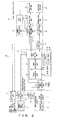
- FIG. 1 is a block diagram of the entirety of a wireless image transmission system according to the present embodiment.
- a wireless image transmission system 100 of FIG. 1 includes a processor 10 and a monitor 20, and the processor 10 and the monitor 20 exchanges an image signal with each other by radio communication.
- FIG. 1 the configuration related to a method for transmitting and receiving an image signal according to the present embodiment is illustrated, and the configurations in other respects are omitted.
- the processor 10 includes a main processor circuit 11, an operation unit 12, a transmission data processing unit 13 and an image transmission unit 14, and the processor 10 performs image processing on the endoscopic images obtained by an endoscope 1.
- the operation unit 12, the transmission data processing unit 13, and the image transmission unit 14 in the configuration of the processor 10 may be installed in a processor, or may be installed as an external unit. The configuration of each element of the processor 10 will be described later in detail with reference to FIG. 2 and the like.
- the monitor 20 includes an image reception unit 21, an operation unit 22 and a main monitor circuit 23, and the monitor 20 displays the image signal received from the processor 10 on a display unit.
- the image reception unit 21 and the operation unit 22 in the configuration of the monitor 20 may be installed in the monitor 20, or may be installed as an external unit. The configuration of each element of the monitor 20 will be described later in detail with reference to FIG. 3 and the like.
- the wireless image transmission system 100 of FIG. 1 edits the color data of an image signal according to a communication state and the characteristics of an endoscopic image that is being transmitted.
- the wireless image transmission system 100 controls the amount of data to be transmitted or received according to the state of radio communication, and continues the transmission of an image signal.
- FIG. 2 is a block diagram of a processor according to the present embodiment.
- the processor 10 of FIG. 2 includes the operation unit 12, a mode setting unit 16, a mode display unit 18, memory 17, the main processor circuit 11, the transmission data processing unit 13, the image transmission unit 14 and an error rate detection unit 15.
- the main processor circuit 11 of the processor 10 includes an imaging circuit 51 and an image processing circuit 52.
- the main processor circuit 11 uses the image processing circuit 52 to perform image processing on the endoscopic images input from the imaging circuit 51 that is arranged at the tip of the inserting part of the endoscope 1.
- the main processor circuit 11 has a color signal generation unit that generates a color signal for each one of a plurality of color signals for generating an image.
- the operation unit 12 accepts various settings of a radio communication or diagnostic mode according to the input operation performed by a user of the wireless image transmission system 100, and the operation unit 12 displays the setting or communication state.
- the diagnostic mode indicates the kind of the image output from the main processor circuit 11 of FIG. 2 , and includes, for example, a normal mode in which a normal endoscopic observation image is displayed, an NBI (Narrow Band Imaging) mode (special light mode) in which a narrow bandwidth light observation image is displayed, and an ultrasonic mode in which an ultrasonic wave observation image is displayed.
- the various settings of a radio communication or diagnostic mode are achieved, for example, by receiving an input from a scope switch, a touch panel on the main body of the processor 10, a panel switch and LED (Light Emitting Diode) display on the main body of the processor 10 in a similar manner to touch panel on the main body of the processor 10, and from an external device via a serial communication.
- the scope switch is arranged such that an operator who performs an endoscopic surgery or the like by using the endoscope 1 will be able to perform a setting operation within a sterilized area.
- the mode setting unit 16 stores the diagnostic mode set through the operation unit 12 in the memory 17, and instructs the mode display unit 18 to output and display the set diagnostic mode.
- the mode setting unit 16 also notifies the transmission data processing unit 13 of notification of the diagnostic mode provided by the operation unit 12.
- the transmission data processing unit 13 processes image such as endoscopic images. In particular, when a communication state is deteriorated, the transmission data processing unit 13 edits the color data of image data according to the notification of the diagnostic mode provided by the mode setting unit 16.
- the transmission data processing unit 13 includes an automatic image detection unit 31, a timer 32, a timing adjustment unit 33, an image multiplexing unit 34, an image memory 35, memory 36 and a color data editing unit 37.
- the automatic image detection unit 31 of the transmission data processing unit 13 analyzes the image input from the main processor circuit 11, and determines a diagnostic mode. How a diagnostic mode is determined will be described later in detail with reference to FIG. 11 .
- the automatic image detection unit 31 performs a chattering control by using the timer 32 such that a diagnostic mode will not be frequently changed due to an automatic detection process of a diagnostic mode.
- the timing adjustment unit 33 synchronizes the image input from the main processor circuit 11 with the OSD (On-Screen Display) image input from the mode display unit 18.
- the image multiplexing unit 34 multiplexes the image and the OSD image synchronized by the timing adjustment unit 33.
- the memory 35 of the transmission data processing unit 13 is used to store an image on a temporary basis for performing a multiplexing process.
- the color data editing unit 37 refers to an edit table 38 of the memory 36, and edits, according to a diagnostic mode, the ratio of the color data of the image data that has been input from the main processor circuit 11 according to a communication state. Then, the color data editing unit 37 reduces the amount of data to be transmitted or received with the monitor 20. In the embodiment, the ratio of the color data is changed according to an error rate. In regard to the deterioration of a communication state, determination is made according to the notification provided by the error rate detection unit 15, as will be described later.
- the color data editing unit 37 edits the ratio of the color data according to a diagnostic mode, and outputs an image signal and the information indicating the edited ratio of the image signal to the image transmission unit 14.
- a diagnostic mode When there are several diagnostic modes, the color data editing unit 37 edits the ratio of the color data according to a diagnostic mode, and outputs an image signal and the information indicating the edited ratio of the image signal to the image transmission unit 14.
- a specific example of how color data is edited will be described in detail with reference to FIG. 6 , FIG. 8 , and the like.
- the image transmission unit 14 includes a radio communication management unit 41, a modulation unit 42, memory 43, an image memory 44, a transmission antenna 45, a reception antenna 46, a demodulation unit 47, and a reception data analysis unit 48.
- the image transmission unit 14 performs a necessary process for an image signal whose color data is edited as necessary by the transmission data processing unit 13, and transmits the image signal by radio.
- the image transmission unit 14 receives a radio signal related to the transmitted image signal from the monitor 20, and performs a necessary process for the received radio signal.
- the radio communication management unit 41 manages the radio communication with the monitor 20 according to the communication system or the like set via the operation unit 12. In particular, the radio communication management unit 41 performs a wireless connection (link) process or a transaction (retransmission control) process. Information to be used for radio communication, for example, information such as the MAC address (Media Access Control address) of the monitor 20 to be connected with is stored in the memory 43.
- a radio modulation technique such as QAM (Quadrature Amplitude Modulation) or QPSK (Quadrature Phase Shift Keying), or a radio transmission system such as polarization technique or MIMO (Multiple Input Multiple Output) will not be specified. Any radio transmission system may be adopted.
- a method for avoiding an error in the event of a radio communication error includes frequency band modification, transmission system modification, retransmission control, or the like, but such an avoiding method is not specified herein and any method may be adopted.
- the modulation unit 42 modulates the image signal input from the transmission data processing unit 13.
- the image memory 44 is used to store image when the modulation unit 42 performs a modulation process.
- the transmission antenna 45 transmits the modulation signal input from the modulation unit 42 to the outside as a radio signal. As described above, an image signal of an endoscopic image is transmitted to the monitor 20 of FIG. 1 . When a radio signal is received from the processor 10, the monitor 20 returns a packet that includes an error rate to the processor 10.
- the reception antenna 46 receives the radio signal transmitted from the monitor 20 in the way described above.
- the demodulation unit 47 demodulates the radio signal received at the reception antenna 46.
- the reception data analysis unit 48 analyzes the received data obtained in the demodulation, and notifies each unit, such as the radio communication management unit 41 and the error rate detection unit 15 of required information, respectively.
- the information provided to the radio communication management unit 41 is required to maintain the radio communication with the monitor 20. This technique is well known in the art, and thus the detailed description is omitted herein.
- the error rate detection unit 15 is notified of the detected error rate.
- the error rate detection unit 15 compares the the notified error rate from the reception data analysis unit 48 of the image transmission unit 14 with a specified threshold, and determines whether or not to notify the color data editing unit 37 of the transmission data processing unit 13 of an error rate. When it is determined that the color data editing unit 37 be notified of an error rate, the error rate detection unit 15 provides notification to the color data editing unit 37. When the mode display unit 18 is capable of displaying a communication state such as an error rate, the error rate detection unit 15 may instruct the operation unit 12 to display the error rate on the mode display unit 18.
- FIG. 3 is a block diagram of a monitor according to the present embodiment.
- the monitor 20 of FIG. 3 includes the image reception unit 21, the main monitor circuit 23, and the operation unit 22.
- the monitor 20 receives the image signal transmitted from the processor 10 by radio communication, and displays an endoscopic image or the like on a screen.
- the operation unit 22 accepts various settings of the radio communication with the processor 10 according to the input operation performed by a user of the wireless image transmission system 100, and displays the details of the settings.
- the various settings of a radio communication are performed, for example, by receiving an input from a touch panel on the main body of the monitor 20, a panel switch and LED display on the main body of the monitor 20 in a similar manner to the touch panel on the main body of the monitor 20, and from an external device via a serial communication.
- the main monitor circuit 23 includes an image processing circuit 71 and a display circuit 72.
- the image processing circuit 71 performs image processing on the image signal received from the processor 10 through the image reception unit 21, and the display circuit 72 performs display on a screen.
- the image reception unit 21 includes a reception antenna 61, a demodulation unit 62, a reception data analysis unit 63, a radio communication management unit 64, memory 65, a modulation unit 66, and a transmission antenna 67.
- the image reception unit 21 receives an image signal or the like from the processor 10 and performs a necessary process for the received image signal or the like, and performs a necessary process for a signal to be transmitted to the processor 10 and transmits the signal by radio.
- the reception antenna 61 receives the radio signal transmitted from the processor 10 of FIG. 2 .
- the demodulation unit 62 demodulates the radio signal received at the reception antenna 61.
- the reception data analysis unit 63 analyzes the data obtained in the demodulation, and calculates an error rate.
- the error rate is calculated, for example, by measuring a baud rate.
- the reception data analysis unit 63 also edits the image signal of the received signal to the image format that may be received by the main monitor circuit 23, and then outputs the signal to the main monitor circuit 23. How an image format is edited will be described with reference to FIG. 10 .
- the radio communication management unit 64 manages the radio communication with the processor 10 according to the communication system or the like that is set via the operation unit 22.
- the radio communication management unit 64 performs a wireless connection (link) process or a transaction (retransmission control) process.
- Information to be used for radio communication for example, information such as the MAC address of the processor 10 to be connected with is stored in the memory 65.
- the modulation unit 66 modulates a signal to be transmitted to the processor 10.
- the transmission antenna 67 transmits the modulation signal input from the modulation unit 66 to the outside as a radio signal.
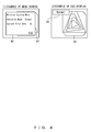
- FIG. 4 illustrates how a diagnostic mode is set. As described above, when a diagnostic mode is designated by a user such as an operator through the operation unit 12 of the processor 10, the processor 10 stores the designated diagnostic mode in the memory 17.
- a setting menu 82 is superimposed on an endoscopic image 81 on a screen of the monitor 20, as illustrated in an example of the menu screen of (1) of FIG. 4 .
- a diagnostic mode 83 set to the endoscopic image 81 is OSD-displayed, as illustrated in an OSD display of (2) of FIG. 4 as an example.
- a user may set a diagnostic mode through a screen of the monitor 20 on which the endoscopic image 81 is displayed even when an endoscopic surgery or the like is being performed.
- the processor 10 maintains the communication by reducing the amount of data accordingly and by changing the ratio of the color data of an image signal.
- the processor 10 from which an image signal is transmitted detects the deterioration of a communication state by referring to a packet indicating an error rate, which is transmitted from the monitor 20.
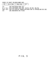
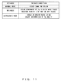
- FIG. 5 illustrates an example of the format of a packet notifying an error rate.
- Data indicating an error rate is included in a specified field of the packet received by the processor 10 from the monitor 20.
- FIG. 5 illustrates an example of the case in which data indicating an error rate is stored in a field "Error Rate".
- an error rate of 0 percent is indicated when data "00h” is stored, and an error rate of 50 percent and an error rate of 75 percent are indicated by data "32h” and data "4Bh", respectively.
- some patterns may be prepared as illustrated in FIG. 5 as examples.
- the maximum value from the prepared values is stored in a field, and notification is provided to the processor 10.
- it may be configured in such a manner that the value of the error rate measured by the radio communication management unit 64 of the monitor 20 is stored in a field without any change and notification is provided to the processor 10.
- the reception data analysis unit 48 of the processor 10 notifies the error rate detection unit 15 of the value stored in the field "Error Rate" of the received packet.
- the error rate detection unit 15 notifies the color data editing unit 37 of the transmission data processing unit 13 of the error rate.
- 50 percent and 75 percent are set as thresholds.
- the color data editing unit 37 determines a portion of the edit table 38 to be referred to according to the error rate notified from the error rate detection unit 15.
- the processor 10 changes the ratio of the color data to be transmitted to the monitor 20 in accordance with a transmission rate.
- the amount of data is reduced by changing the ratio of the color data in such a manner that the influence on the image quality of an endoscopic image is minimized according to a diagnostic mode, i.e., according to what sort of observation image the endoscopic image is.
- a method for changing the ratio of the color data firstly, there is a method achieved by reducing the number of bits, and secondly, there is another method achieved by reducing the number of pixels. Next, such methods for changing the ratio of the color data will be described in a specific manner with reference to FIGs. 6-9 .
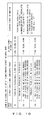
- FIG. 6 illustrates an example of the configuration of the edit table 38 of color data, which is used when the method achieved by reducing the number of bits is adopted. A method for setting the ratio of the color data according to an error rate and a diagnostic mode will be described with reference to FIG. 6 .
- the edit table 38 defines how the number of the bits of color data is reduced depending on whether the diagnostic mode is defined to which of "normal mode”, “NBI mode”, and “ultrasonic mode", with each case of the error rate being "0 percent”, “50 percent”, and "75 percent”, respectively.
- the error rate is changed from 0 percent to over 50 percent while an endoscopic image obtained in the normal mode is being transmitted. While the error rate is 0 percent, the ratio of the color data is determined by referring to the first line L1, the first column C1 in the edit table 38. In this case, the number of bits is not reduced, and all (100 percent) bits of luminance Y and color differences Pb and Pr in the bits of the image signal input from the main processor circuit 11 are transmitted.
- the error rate becomes over 50 percent
- the place to be referred to in the edit table 38 is changed to the second line L2, the first column C1.
- the number of the bits of the image signal input from the main processor circuit 11 is reduced.
- the bits of luminance Y is reduced to 80 percent, and the bits of a color difference Pb and a color difference Pr are reduced to 25 percent and 45 percent, respectively.
- an appropriate ratio of the color data is set for every diagnostic mode according to the characteristics of an observation image, such that the influence on the image quality of an endoscopic image due to the performed reduction process will be minimized.
- information that prioritizes information of a plurality of color signals according to a diagnostic mode i.e., the characteristics of an observation image.
- images in the ultrasonic mode are basically monochrome images.
- images in the normal mode are basically color images.
- the ratio of the color data is set higher in Pr than in Pb such that Pr information that has a high correlation with red will be transmitted on a priority basis. Accordingly, it becomes unlikely that the observation of an image is impaired.
- the ratio of the color data is set higher in Pb than in Pr such that Pb information that has a high correlation with blue will be transmitted on a priority basis.
- FIG. 6 merely illustrates an example of how the ratio between luminance Y and color differences Pb and Pr is set and no limitation is indicated therein.
- the ratio may be determined appropriately according to the characteristics of images in each diagnostic mode and an error rate.
- FIG. 6 illustrates three error rates and three diagnostic modes, but no limitation is indicated therein.
- the ratio of the color data may be defined for further different error rates, or the ratio of the color data may be defined for other diagnostic modes. It is not necessary for the value of an error rate to be one of 0 percent, 50 percent, and 75 percent, and other values may be set. Further, it is not always necessary to define all the diagnostic modes or error rates of FIG. 6 .
- the color data editing unit 37 of the transmission data processing unit 13 edits the color data according to the definition in the edit table 38 of FIG. 6 , and passes the edited image signal to the image transmission unit 14. Moreover, the color data editing unit 37 generates format information that indicates at what ratio the color data of an image signal is edited, and passes the generated format information to the image transmission unit 14.
- FIG. 7 depicts an example of the signal that the processor 10 transmits in the case where the color data is edited according to the edit table 38 of FIG. 6 .
- the processor 10 transfers an image signal and information that indicates how the ratio of the color data of an image signal is edited to the monitor 20 in the case where the ratio of the color data is edited according to the definition in the edit table 38 of FIG. 6 will be specifically described with reference to FIG. 7 .
- FIG. 7 (a) depicts an example of the signal that is output to the image transmission unit 14 by the transmission data processing unit 13 of the processor 10.
- FIG. 7 (a) depicts an example of the signal that is output to the image transmission unit 14 by the transmission data processing unit 13 of the processor 10.
- examples of the configuration of a signal that corresponds to each error rate when the diagnostic mode is "normal mode" are depicted.
- a signal that is transmitted to the monitor 20 via the image transmission unit 14 of the processor 10 includes color data, i.e., an image signal indicating an endoscopic image (this will be referred to as "a"), and a signal of format information indicating the ratio of the color data of an image signal.
- An "image signal a" in (1) includes the bits whose number of bits is reduced according to the definition in the edit table 38 of FIG. 6 .
- FIG. 7 (a) depicts the image signal that is edited according to line L1, columns C1-C3 of the edit table 38 of FIG. 6 .
- the image signals a that correspond to the error rates when the diagnostic mode is set to the "normal mode" are depicted as examples in (1) of FIG. 7 . Also when the diagnostic modes other than the normal mode are adopted, the number of bits is reduced according to the reduction rate defined in each place to be referred to in the edit table 38 of FIG. 6 with reference to the number of bits when the error rate is 0 percent. A known technique in the art is used to reduce the number of bits.
- Format information in (2) includes information that indicates how many bits of the luminance Y and color differences Pb and Pr in the image signal a are reduced respectively. For example, when the error rate is 50 percent in the normal mode, the format information includes information indicating that the data where the luminance Y, color difference Pb, and color difference Pr are reduced to 80 percent, 25 percent, and 45 percent, respectively, is transmitted as the image signal a.
- the format information is transmitted in a format depicted in FIG. 7 (b) .
- a value that indicates the diagnostic mode is stored in the front field "Operation Mode”.
- the data lengths of the luminance Y and color differences Pb and Pr are stored in the subsequent fields "Y data length”, “Pb data length”, and “Pr data length”, respectively.
- the data length of each color data of the luminance Y and color differences Pb and Pr is represented as percentage of how much bit length is included in the image signal a, where the bit length is 100 percent in the case the error rate is 0 percent and no compression is present.
- the format information is transmitted, for example, by using a blanking period of an image frame including the image signal a.
- FIG. 8 illustrates an example of the configuration of the edit table 38 of color data, which is used when the method achieved by reducing the number of pixels is adopted.
- the other method for setting the ratio of the color data according to an error rate and a diagnostic mode will be described with reference to FIG. 8 .
- FIG. 8 depicts only the edit table 38 related to the normal mode.
- the values same as those used for reducing the number of bits in FIG. 6 are set to the ratios at which color data with each error rate is compressed.
- the depiction is omitted in FIG. 8
- color data is compressed at the ratios whose values are same as those used for reducing the number of bits with each error rate in FIG. 6 when the other diagnostic modes are adopted.
- a specified number of pixels defined by the edit table 38 from among pixels constituting each image frame are not transmitted, thereby reducing the color data of pixels constituting each image frame to a specified rate.
- whether or not to transmit color data is determined according to the pixel number of a pixel included in each image frame.
- pixels with pixel numbers 1-20 in FIG. 8 pixels whose color data is transmitted to the monitor 20 are indicated with luminance Y and color differences Pb and Pr.
- Data with a pixel number with no indication of a reference sign (Y, Pb, or Pr) in the edit table 38 is to be deleted in the color data editing unit 37, and is not to be transmitted to the monitor 20.
- the error rate is 75 percent
- the information of a pixel with pixel number 2 is not transmitted to the monitor 20, and only the information of luminance Y of a pixel is transmitted to the monitor 20 in regard to the pixel information with pixel number 3.
- FIG. 8 illustrates an example of how the number of pixels is reduced. Whether or not to transmit which of luminance Y, and color differences Pb and Pr of what pixel may be determined without any limitation as long as specified rates (for example, when the error rate is 50 percent in the normal mode, luminance Y, a color difference Pb, and a color difference Pr are reduced to 80 percent, 25 percent, and 45 percent, respectively) are satisfied.
- any number of diagnostic modes or error rates may be defined in the edit table 38 where the number of pixels is reduced.
- which diagnostic mode is to be defined what value is to be set to the value of an error rate or the like may be determined without limitation.
- FIG. 9 depicts an example of the signal that the processor 10 transmits in the case where the color data is edited according to the edit table 38 of FIG. 8 .
- the processor 10 transfers an image signal and information that indicates how the ratio of the color data of an image signal is edited to the monitor 20 in the case where the ratio of the color data is edited according to the definition in the edit table 38 of FIG. 8 will be specifically described with reference to FIG. 9 .
- differences from an example of the signal described above with reference to FIG. 7 will be mainly described.
- FIG. 9 (a) depicts an example of the signal that is output to the image transmission unit 14 by the transmission data processing unit 13 of the processor 10.
- FIG. 9 (a) depicts an example of the signal that is output to the image transmission unit 14 by the transmission data processing unit 13 of the processor 10.
- examples of the configuration of a signal that corresponds to each error rate when the diagnostic mode is "normal mode" are depicted.
- a signal to be transmitted to the monitor 20 in the method achieved by reducing the number of pixels also includes an image signal (this will be referred to as "b") and a signal of format information.
- the color data with specified pixel numbers is reduced in the image signal b of (1) according to the edit table 38 of FIG. 8 .
- Information similar to that of FIG. 7 (a) is stored as (2) format information.
- the format of format information is similar to the format of FIG. 7 (b) where the method achieved by reducing the number of bits is adopted, and a value that indicates the diagnostic mode, and the data length of the luminance Y and color differences Pb and Pr are stored therein in the order from the front field.
- the data length of the luminance Y and color differences Pb and Pr is represented as percentage of how much pixel from among pixels that constitutes a single image frame is included in the image signal b.
- the monitor 20 uses the radio communication management unit 64 of the image reception unit 21 to determine how much luminance Y and color differences Pb and Pr are reduced according to the received format information. Then, the radio communication management unit 64 of the image reception unit 21 interpolates the bits or pixels reduced from the image signals a and b according to a rate at which the luminance Y and color differences Pb and Pr are reduced, and displays the obtained image signal on a screen.
- FIG. 10 depicts processes in which color data of the signal received from the processor 10 is interpolated by the radio communication management unit 64 of the monitor 20 and the signal is output.
- the columns of FIG. 10 indicates (1) the image signal a or b that is input to the radio communication management unit 64 of the monitor 20, (2) the format information that is input to the radio communication management unit 64, and (3) the output format information that is generated by the radio communication management unit 64, respectively.
- the radio communication management unit 64 interpolates image signal a or b in (1) according to the format information (2) received from the processor 10, and edits the image signal so as to be in an image format that can be processed by the main monitor circuit 23 of FIG. 3 .
- Output format information in (3) is obtained by performing an interpolation process as necessary. For example, in the case where the number of bits is reduced, the removed bits are filled with "0". In the case where the number of pixels is reduced, an interpolation process, for example, a process in which the previous pixel is copied or the removed pixel is filled with a specific value (for example, "0"), is performed appropriately.
- the diagnostic mode may be recognized by analyzing the color information of the image input from the main processor circuit 11 by the automatic image detection unit 31 of the transmission data processing unit 13.
- FIG. 11 depicts how the automatic image detection unit 31 recognizes the diagnostic mode from the color information of image.
- the automatic image detection unit 31 may determine that the diagnostic mode is the NBI mode when the color component of a color difference Pb is N or more times greater than the color component of a color difference Pr.
- the automatic image detection unit 31 may determine that the diagnostic mode is the ultrasonic mode when the color information does not include any component of the color differences Pb and Pr.
- the automatic image detection unit 31 determines that the diagnostic mode is the normal mode when the diagnostic mode is neither the NBI mode nor the ultrasonic mode.
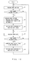
- FIG. 12 is a flowchart of a color data editing process performed by the color data editing unit 37 of the processor 10 according to the present embodiment.
- step S1 the diagnostic mode stored in the memory 17 is read via the mode setting unit 16.
- step S2 whether or not the set diagnostic mode has been changed by the operation unit 12 is determined.
- the determination in step S2 is made, for example, depending on whether or not the diagnostic mode stored in the memory 36 or the like of the transmission data processing unit 13 matches the diagnostic mode read in step S1.
- the color data is edited as necessary according to the method defined in a predetermined place to be referred to in the edit table 38, and the process shifts to step S5.
- the process shifts to step S3.
- step S3 various settings are changed according to the diagnostic mode read in step S1.
- the diagnostic mode read in step S1 is written into the memory 36 or the like of the transmission data processing unit 13, and the places to be referred to are changed in the edit table 38.
- step S4 information is read from relevant places of the changed edit table 38, and the color data is edited accordingly. Then, the process shifts to step S5.
- step S5 an error rate is read from the memory 36.
- step S6 whether or not there has been a change in the error rate is determined.
- the determination in step S6 is made depending on whether or not the read error rate is greater (or less) than a threshold, where the value of an error rate set to the edit table 38 is the threshold.
- the of the latest error rate notified by the error rate detection unit 15 is held in the memory 36.
- an image signal including the color data is output to the image transmission unit 14, and the process returns to step S1.
- the process shifts to step S7.
- step S7 places to be referred to are changed in the edit table 38.
- step S8 information is read from relevant places of the edit table 38, and the color data is edited accordingly. Then, an image signal including the color data is output to the image transmission unit 14, and the process returns to step S1.
- the color data editing unit 37 changes the place to be referred to in the edit table 38 when the set diagnostic mode has been changed or when the notified error rate provided by the monitor 20 has been changed to a degree greater than a specified threshold. Then, the color data will be edited according to the method defined in the changed place to be referred to.
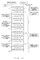
- FIG. 13 illustrates specific examples of the sequences in which an endoscopic image is exchanged between the processor 10 and the monitor 20 by using the methods as above.
- the monitor 20 notifies the processor 10 of the fact that the error rate is 0 percent by using a packet P1 or the like.
- the packet that the monitor 20 returns to the processor 10 in response to a frame with frame number N is represented as "packet PN".
- the monitor 20 will provide a packet P2 and the following packets with notification that the error rate is 50 percent.
- the processor 10 determines that the error rate has become greater than the first threshold (50 percent), and changes the place to be referred to in the edit table 38. After the place to be referred to has been changed, a frame F4 and the following frames are transmitted, for example, upon compressing luminance Y, a color difference Pb, and a color difference Pr to 80 percent, 25 percent, and 45 percent, respectively. While the transmission rate is 50 percent, the monitor 20 similarly responds to the frames that have received the notification that the error rate is 50 percent.
- the first threshold 50 percent
- the processor 10 changes the place to be referred to in the edit table 38. After the place to be referred to has been changed, a frame F101 and the following frames are transmitted, for example, upon compressing luminance Y, a color difference Pb, and a color difference Pr to 80 percent, 45 percent, and 25 percent, respectively.
- the monitor 20 will provide notification that the error rate is 75 percent with a packet P1000 and the following packets.
- the processor 10 determines that the error rate has become greater than the second threshold (75 percent), and changes the place to be referred to in the edit table 38. After the place to be referred to has been changed, a frame F1002 and the following frames are transmitted, for example, upon compressing luminance Y, a color difference Pb, and a color difference Pr to 50 percent, 15 percent, and 10 percent, respectively.
- the monitor 20 will provide notification that the error rate is 0 percent with a packet P1999 and the following packets.
- the processor 10 determines that the error rate has become less than the first and second thresholds, and changes the place to be referred to in the edit table 38. After the place to be referred to has been changed, a frame F2001 and the following frames are transmitted, for example, with luminance Y, a color difference Pb, and a color difference Pr just as they are (without compression).
- the color data editing unit 37 of the transmission data processing unit 13 reduces the amount of color data to be transmitted in accordance with an error rate and a diagnostic mode to maintain the communication.
- the compression rate of color data is set so as to minimize the influence on the image quality according to a diagnostic mode, i.e., according to the characteristics of an endoscopic image. Accordingly, sufficient image quality is secured for the endoscopic image displayed on the monitor 20 when a user such as an operator of the wireless image transmission system 100 performs an endoscopic observation or the like.
Abstract
Description
- The present invention relates to a color signal transmission device, a wireless image transmission system, and a transmitter for transmitting an image from a transmitter to a receiver.
- A wireless endoscope system that transmits and receives an image signal by radio is known in the art to replace a conventionally used endoscope system by which an endoscopic image or the like is transmitted through an image cable and is displayed on a monitor.
- A wireless endoscope system has a characteristic that an image signal is transmitted by radio communication, and thus the traffic or communication rate may drop as affected by disturbance, noise or the like. For the purposes of compensating for the above, conventionally, a frame rate is changed or an image is compressed by reducing some color data of the image in order to maintain the communication (see, for example,
Patent Documents 1 and 2). - A technique by which normal light observation and special light observation can be performed is also disclosed as a known technique in the art related to a medical endoscope apparatus (see, for example, Patent Document 3).
-
- Patent Document 1: Japanese Laid-open Patent Publication No.
2009-172280 - Patent Document 2: Japanese Laid-open Patent Publication No.
2006-122586 - Patent Document 3: Japanese Laid-open Patent Publication No.
2011-041758 - As described above, according to the conventional art, when the traffic or communication rate has dropped in radio communication, specified processes such as a change of a frame rate or image compression are uniformly performed. Even when a communication state is deteriorated, it is desired that communication be continued by precisely controlling the amount of data to be transmitted or received according to the characteristics of transmitting and receiving endoscopic images.
- A color signal transmission device according to one aspect of the present invention includes: a first color signal generation unit to generate a first color signal from among a plurality of color signals for creating an image; a second color signal generation unit to generate a second color signal from among a plurality of color signals for creating an image; a diagnostic mode selection unit capable of selecting either a first diagnostic mode for creating a first diagnostic image by using the first color signal and the second color signal, or a second diagnostic mode for creating a second diagnostic image that is different from the first diagnostic mode; a priority determination unit to determine superiority of information among color signals generated by the first color signal generation unit and the second color signal generation unit, according to a diagnostic mode selected by the diagnostic mode selection unit; a transmission rate changing unit to change transmission rates of the first color signal generated by the first color signal generation unit and the second color signal generated by the second color signal generation unit, according to a priority determined by the priority determination unit; and a color signal transmission unit to transmit the first color signal and the second color signal according to a transmission rate changed by the transmission rate changing unit.
- A transmitter according to another aspect of the present invention is used in a wireless image transmission system that transmits and receives, by radio communication, an image signal obtained by converting an image that is obtained by an endoscope apparatus, and the transmitter includes: a communication state detection unit to monitor a communication state of radio communication; an editing unit to edit the image signal according to a mode in which the endoscope apparatus obtains an image when a change in a communication state is detected by the communication state detection unit; and
a transmission unit to transmit the image signal output from the editing unit to a receiver. - A wireless image transmission system according to one aspect of the present invention includes a transmitter to transmit, by radio communication, an image signal obtained by converting an image that is obtained by an endoscope apparatus, and a receiver having a display unit on which the image signal received from the transmitter is displayed, the transmitter including: a communication state detection unit to monitor a communication state of radio communication; an editing unit to edit the image signal according to a mode in which the endoscope apparatus obtains an image when a change in a communication state is detected by the communication state detection unit; and a transmission unit to transmit the image signal output from the editing unit to a receiver, and the receiver including an analysis unit to edit an image signal received from the transmitter into a format enabling the image signal to be displayed on the display unit, and to detect a communication state.
- According to the present invention, when an endoscopic image is transmitted or received by radio communication, it becomes possible to continue communication by precisely editing the transmitted or received data according to the characteristics of transmitting and receiving endoscopic images.
- The present invention will be more apparent from the following detailed description when the accompanying drawings are referenced.
-
FIG. 1 is a block diagram of the entirety of a wireless image transmission system according to an embodiment. -
FIG. 2 is a block diagram of a processor according to an embodiment. -
FIG. 3 is a block diagram of a monitor according to an embodiment. -
FIG. 4 illustrates how a diagnostic mode is set. -
FIG. 5 illustrates an example of the format of a packet notifying an error rate. -
FIG. 6 illustrates an example of the configuration of an edit table of color data, which is used when the method achieved by reducing the number of bits is adopted. -
FIG. 7 depicts an example of the signal that a processor transmits in the case where color data is edited according to an edit table ofFIG. 6 . -
FIG. 8 illustrates an example of the configuration of an edit table of color data, which is used when the method achieved by reducing the number of pixels is adopted. -
FIG. 9 depicts an example of the signal that a processor transmits in the case where the color data is edited according to the edit table ofFIG. 8 . -
FIG. 10 depicts processes in which color data of the signal received from a processor is interpolated by a monitor and the signal is output. -
FIG. 11 depicts an example of how an automatic image detection unit recognizes a diagnostic mode from the color information of image. -
FIG. 12 is a flowchart of a color data editing process performed by a color data editing unit. -
FIG. 13 illustrates specific examples of the sequences in which an endoscopic image is exchanged between a processor and a monitor. - Some embodiments of the present invention will be described in detail with reference to the drawings.
-
FIG. 1 is a block diagram of the entirety of a wireless image transmission system according to the present embodiment. A wirelessimage transmission system 100 ofFIG. 1 includes aprocessor 10 and amonitor 20, and theprocessor 10 and themonitor 20 exchanges an image signal with each other by radio communication. InFIG. 1 , the configuration related to a method for transmitting and receiving an image signal according to the present embodiment is illustrated, and the configurations in other respects are omitted. - The
processor 10 includes amain processor circuit 11, anoperation unit 12, a transmissiondata processing unit 13 and animage transmission unit 14, and theprocessor 10 performs image processing on the endoscopic images obtained by anendoscope 1. Theoperation unit 12, the transmissiondata processing unit 13, and theimage transmission unit 14 in the configuration of theprocessor 10 may be installed in a processor, or may be installed as an external unit. The configuration of each element of theprocessor 10 will be described later in detail with reference toFIG. 2 and the like. - The
monitor 20 includes animage reception unit 21, anoperation unit 22 and amain monitor circuit 23, and themonitor 20 displays the image signal received from theprocessor 10 on a display unit. Theimage reception unit 21 and theoperation unit 22 in the configuration of themonitor 20 may be installed in themonitor 20, or may be installed as an external unit. The configuration of each element of themonitor 20 will be described later in detail with reference toFIG. 3 and the like. - When a deterioration or the like is detected in the state of radio communication while an endoscopic image is being transmitted by radio communication from the
processor 10 to themonitor 20, the wirelessimage transmission system 100 ofFIG. 1 edits the color data of an image signal according to a communication state and the characteristics of an endoscopic image that is being transmitted. The wirelessimage transmission system 100 controls the amount of data to be transmitted or received according to the state of radio communication, and continues the transmission of an image signal. - The configuration and operation of each element of the
processor 10 and themonitor 20 of the wirelessimage transmission system 100 according to the present embodiment will be described below in detail. -
FIG. 2 is a block diagram of a processor according to the present embodiment. Theprocessor 10 ofFIG. 2 includes theoperation unit 12, amode setting unit 16, amode display unit 18,memory 17, themain processor circuit 11, the transmissiondata processing unit 13, theimage transmission unit 14 and an errorrate detection unit 15. - The
main processor circuit 11 of theprocessor 10 includes animaging circuit 51 and animage processing circuit 52. Themain processor circuit 11 uses theimage processing circuit 52 to perform image processing on the endoscopic images input from theimaging circuit 51 that is arranged at the tip of the inserting part of theendoscope 1. Themain processor circuit 11 has a color signal generation unit that generates a color signal for each one of a plurality of color signals for generating an image. - The
operation unit 12 accepts various settings of a radio communication or diagnostic mode according to the input operation performed by a user of the wirelessimage transmission system 100, and theoperation unit 12 displays the setting or communication state. The diagnostic mode indicates the kind of the image output from themain processor circuit 11 ofFIG. 2 , and includes, for example, a normal mode in which a normal endoscopic observation image is displayed, an NBI (Narrow Band Imaging) mode (special light mode) in which a narrow bandwidth light observation image is displayed, and an ultrasonic mode in which an ultrasonic wave observation image is displayed. The various settings of a radio communication or diagnostic mode are achieved, for example, by receiving an input from a scope switch, a touch panel on the main body of theprocessor 10, a panel switch and LED (Light Emitting Diode) display on the main body of theprocessor 10 in a similar manner to touch panel on the main body of theprocessor 10, and from an external device via a serial communication. Note that the scope switch is arranged such that an operator who performs an endoscopic surgery or the like by using theendoscope 1 will be able to perform a setting operation within a sterilized area. - The
mode setting unit 16 stores the diagnostic mode set through theoperation unit 12 in thememory 17, and instructs themode display unit 18 to output and display the set diagnostic mode. Themode setting unit 16 also notifies the transmissiondata processing unit 13 of notification of the diagnostic mode provided by theoperation unit 12. - The transmission
data processing unit 13 processes image such as endoscopic images. In particular, when a communication state is deteriorated, the transmissiondata processing unit 13 edits the color data of image data according to the notification of the diagnostic mode provided by themode setting unit 16. - The transmission
data processing unit 13 includes an automaticimage detection unit 31, a timer 32, atiming adjustment unit 33, animage multiplexing unit 34, animage memory 35,memory 36 and a colordata editing unit 37. - It may be configured such that the diagnostic mode will be automatically detected by the
processor 10 via theoperation unit 12. In such cases, the automaticimage detection unit 31 of the transmissiondata processing unit 13 analyzes the image input from themain processor circuit 11, and determines a diagnostic mode. How a diagnostic mode is determined will be described later in detail with reference toFIG. 11 . The automaticimage detection unit 31 performs a chattering control by using the timer 32 such that a diagnostic mode will not be frequently changed due to an automatic detection process of a diagnostic mode. - The
timing adjustment unit 33 synchronizes the image input from themain processor circuit 11 with the OSD (On-Screen Display) image input from themode display unit 18. - The
image multiplexing unit 34 multiplexes the image and the OSD image synchronized by thetiming adjustment unit 33. Thememory 35 of the transmissiondata processing unit 13 is used to store an image on a temporary basis for performing a multiplexing process. - When a communication state is deteriorated, the color
data editing unit 37 refers to an edit table 38 of thememory 36, and edits, according to a diagnostic mode, the ratio of the color data of the image data that has been input from themain processor circuit 11 according to a communication state. Then, the colordata editing unit 37 reduces the amount of data to be transmitted or received with themonitor 20. In the embodiment, the ratio of the color data is changed according to an error rate. In regard to the deterioration of a communication state, determination is made according to the notification provided by the errorrate detection unit 15, as will be described later. When there are several diagnostic modes, the colordata editing unit 37 edits the ratio of the color data according to a diagnostic mode, and outputs an image signal and the information indicating the edited ratio of the image signal to theimage transmission unit 14. A specific example of how color data is edited will be described in detail with reference toFIG. 6 ,FIG. 8 , and the like. - The
image transmission unit 14 includes a radiocommunication management unit 41, amodulation unit 42,memory 43, animage memory 44, atransmission antenna 45, areception antenna 46, ademodulation unit 47, and a receptiondata analysis unit 48. Theimage transmission unit 14 performs a necessary process for an image signal whose color data is edited as necessary by the transmissiondata processing unit 13, and transmits the image signal by radio. Moreover, theimage transmission unit 14 receives a radio signal related to the transmitted image signal from themonitor 20, and performs a necessary process for the received radio signal. - The radio
communication management unit 41 manages the radio communication with themonitor 20 according to the communication system or the like set via theoperation unit 12. In particular, the radiocommunication management unit 41 performs a wireless connection (link) process or a transaction (retransmission control) process. Information to be used for radio communication, for example, information such as the MAC address (Media Access Control address) of themonitor 20 to be connected with is stored in thememory 43. - In the embodiment, a radio modulation technique such as QAM (Quadrature Amplitude Modulation) or QPSK (Quadrature Phase Shift Keying), or a radio transmission system such as polarization technique or MIMO (Multiple Input Multiple Output) will not be specified. Any radio transmission system may be adopted. A method for avoiding an error in the event of a radio communication error includes frequency band modification, transmission system modification, retransmission control, or the like, but such an avoiding method is not specified herein and any method may be adopted.
- The
modulation unit 42 modulates the image signal input from the transmissiondata processing unit 13. Theimage memory 44 is used to store image when themodulation unit 42 performs a modulation process. - The
transmission antenna 45 transmits the modulation signal input from themodulation unit 42 to the outside as a radio signal. As described above, an image signal of an endoscopic image is transmitted to themonitor 20 ofFIG. 1 . When a radio signal is received from theprocessor 10, themonitor 20 returns a packet that includes an error rate to theprocessor 10. - The
reception antenna 46 receives the radio signal transmitted from themonitor 20 in the way described above. - The
demodulation unit 47 demodulates the radio signal received at thereception antenna 46. - The reception
data analysis unit 48 analyzes the received data obtained in the demodulation, and notifies each unit, such as the radiocommunication management unit 41 and the errorrate detection unit 15 of required information, respectively. The information provided to the radiocommunication management unit 41 is required to maintain the radio communication with themonitor 20. This technique is well known in the art, and thus the detailed description is omitted herein. The errorrate detection unit 15 is notified of the detected error rate. - The error
rate detection unit 15 compares the the notified error rate from the receptiondata analysis unit 48 of theimage transmission unit 14 with a specified threshold, and determines whether or not to notify the colordata editing unit 37 of the transmissiondata processing unit 13 of an error rate. When it is determined that the colordata editing unit 37 be notified of an error rate, the errorrate detection unit 15 provides notification to the colordata editing unit 37. When themode display unit 18 is capable of displaying a communication state such as an error rate, the errorrate detection unit 15 may instruct theoperation unit 12 to display the error rate on themode display unit 18. -
FIG. 3 is a block diagram of a monitor according to the present embodiment. Themonitor 20 ofFIG. 3 includes theimage reception unit 21, themain monitor circuit 23, and theoperation unit 22. Themonitor 20 receives the image signal transmitted from theprocessor 10 by radio communication, and displays an endoscopic image or the like on a screen. - The
operation unit 22 accepts various settings of the radio communication with theprocessor 10 according to the input operation performed by a user of the wirelessimage transmission system 100, and displays the details of the settings. The various settings of a radio communication are performed, for example, by receiving an input from a touch panel on the main body of themonitor 20, a panel switch and LED display on the main body of themonitor 20 in a similar manner to the touch panel on the main body of themonitor 20, and from an external device via a serial communication. - The
main monitor circuit 23 includes animage processing circuit 71 and adisplay circuit 72. Theimage processing circuit 71 performs image processing on the image signal received from theprocessor 10 through theimage reception unit 21, and thedisplay circuit 72 performs display on a screen. - The
image reception unit 21 includes areception antenna 61, ademodulation unit 62, a receptiondata analysis unit 63, a radiocommunication management unit 64,memory 65, amodulation unit 66, and atransmission antenna 67. Theimage reception unit 21 receives an image signal or the like from theprocessor 10 and performs a necessary process for the received image signal or the like, and performs a necessary process for a signal to be transmitted to theprocessor 10 and transmits the signal by radio. - The
reception antenna 61 receives the radio signal transmitted from theprocessor 10 ofFIG. 2 . - The
demodulation unit 62 demodulates the radio signal received at thereception antenna 61. - The reception
data analysis unit 63 analyzes the data obtained in the demodulation, and calculates an error rate. The error rate is calculated, for example, by measuring a baud rate. The receptiondata analysis unit 63 also edits the image signal of the received signal to the image format that may be received by themain monitor circuit 23, and then outputs the signal to themain monitor circuit 23. How an image format is edited will be described with reference toFIG. 10 . - The radio
communication management unit 64 manages the radio communication with theprocessor 10 according to the communication system or the like that is set via theoperation unit 22. In particular, the radiocommunication management unit 64 performs a wireless connection (link) process or a transaction (retransmission control) process. Information to be used for radio communication, for example, information such as the MAC address of theprocessor 10 to be connected with is stored in thememory 65. - The
modulation unit 66 modulates a signal to be transmitted to theprocessor 10. - The
transmission antenna 67 transmits the modulation signal input from themodulation unit 66 to the outside as a radio signal. -
FIG. 4 illustrates how a diagnostic mode is set. As described above, when a diagnostic mode is designated by a user such as an operator through theoperation unit 12 of theprocessor 10, theprocessor 10 stores the designated diagnostic mode in thememory 17. - As a technique in which a user sets a diagnostic mode, a setting
menu 82 is superimposed on anendoscopic image 81 on a screen of themonitor 20, as illustrated in an example of the menu screen of (1) ofFIG. 4 . Alternatively, adiagnostic mode 83 set to theendoscopic image 81 is OSD-displayed, as illustrated in an OSD display of (2) ofFIG. 4 as an example. A user may set a diagnostic mode through a screen of themonitor 20 on which theendoscopic image 81 is displayed even when an endoscopic surgery or the like is being performed. - As described above, when a communication state is deteriorated while an endoscopic image is being transmitted by radio communication in the wireless
image transmission system 100 according to the present embodiment, theprocessor 10 maintains the communication by reducing the amount of data accordingly and by changing the ratio of the color data of an image signal. Theprocessor 10 from which an image signal is transmitted detects the deterioration of a communication state by referring to a packet indicating an error rate, which is transmitted from themonitor 20. -
FIG. 5 illustrates an example of the format of a packet notifying an error rate. Data indicating an error rate is included in a specified field of the packet received by theprocessor 10 from themonitor 20.FIG. 5 illustrates an example of the case in which data indicating an error rate is stored in a field "Error Rate". In the example ofFIG. 5 , an error rate of 0 percent is indicated when data "00h" is stored, and an error rate of 50 percent and an error rate of 75 percent are indicated by data "32h" and data "4Bh", respectively. - In regard to the values to be stored in a field "Error Rate", some patterns may be prepared as illustrated in
FIG. 5 as examples. In such cases, when the value of the error rate measured by the radiocommunication management unit 64 of themonitor 20 exceeds a prepared value, the maximum value from the prepared values is stored in a field, and notification is provided to theprocessor 10. Alternatively, it may be configured in such a manner that the value of the error rate measured by the radiocommunication management unit 64 of themonitor 20 is stored in a field without any change and notification is provided to theprocessor 10. - The reception
data analysis unit 48 of theprocessor 10 notifies the errorrate detection unit 15 of the value stored in the field "Error Rate" of the received packet. When the error rate in the notification exceeds a specified threshold, the errorrate detection unit 15 notifies the colordata editing unit 37 of the transmissiondata processing unit 13 of the error rate. In the embodiment, 50 percent and 75 percent are set as thresholds. The colordata editing unit 37 determines a portion of the edit table 38 to be referred to according to the error rate notified from the errorrate detection unit 15. - As described above, the
processor 10 changes the ratio of the color data to be transmitted to themonitor 20 in accordance with a transmission rate. In the embodiment, when a plurality of diagnostic modes are prepared, the amount of data is reduced by changing the ratio of the color data in such a manner that the influence on the image quality of an endoscopic image is minimized according to a diagnostic mode, i.e., according to what sort of observation image the endoscopic image is. As a method for changing the ratio of the color data, firstly, there is a method achieved by reducing the number of bits, and secondly, there is another method achieved by reducing the number of pixels. Next, such methods for changing the ratio of the color data will be described in a specific manner with reference toFIGs. 6-9 . -
FIG. 6 illustrates an example of the configuration of the edit table 38 of color data, which is used when the method achieved by reducing the number of bits is adopted. A method for setting the ratio of the color data according to an error rate and a diagnostic mode will be described with reference toFIG. 6 . - As illustrated in
FIG. 6 , the edit table 38 defines how the number of the bits of color data is reduced depending on whether the diagnostic mode is defined to which of "normal mode", "NBI mode", and "ultrasonic mode", with each case of the error rate being "0 percent", "50 percent", and "75 percent", respectively. - For example, it is assumed that the error rate is changed from 0 percent to over 50 percent while an endoscopic image obtained in the normal mode is being transmitted. While the error rate is 0 percent, the ratio of the color data is determined by referring to the first line L1, the first column C1 in the edit table 38. In this case, the number of bits is not reduced, and all (100 percent) bits of luminance Y and color differences Pb and Pr in the bits of the image signal input from the
main processor circuit 11 are transmitted. When the error rate becomes over 50 percent, the place to be referred to in the edit table 38 is changed to the second line L2, the first column C1. In this case, the number of the bits of the image signal input from themain processor circuit 11 is reduced. The bits of luminance Y is reduced to 80 percent, and the bits of a color difference Pb and a color difference Pr are reduced to 25 percent and 45 percent, respectively. - The other diagnostic modes or different error rates are handled in a similar manner to the above. Relevant lines L1-L3 and columns C1-C3 on the edit table 38 are referred to, and the numbers of the bits of luminance Y and color differences Pb and Pr are reduced at the rate defined in each place to be referred to.
- In the edit table 38 that is illustrated in
FIG. 6 as an example, an appropriate ratio of the color data is set for every diagnostic mode according to the characteristics of an observation image, such that the influence on the image quality of an endoscopic image due to the performed reduction process will be minimized. In particular, in the edit table 38, information that prioritizes information of a plurality of color signals according to a diagnostic mode, i.e., the characteristics of an observation image, is set. For example, it is unlikely that the observation of an ultrasonic image by a user such as an operator is impaired even when a certain amount of the information of color differences Pb and Pr is cut off. This is because images in the ultrasonic mode are basically monochrome images. By contrast, images in the normal mode are basically color images. For this reason, the ratio of the color data is set higher in Pr than in Pb such that Pr information that has a high correlation with red will be transmitted on a priority basis. Accordingly, it becomes unlikely that the observation of an image is impaired. As for images in the NBI mode, the ratio of the color data is set higher in Pb than in Pr such that Pb information that has a high correlation with blue will be transmitted on a priority basis. - Note that
FIG. 6 merely illustrates an example of how the ratio between luminance Y and color differences Pb and Pr is set and no limitation is indicated therein. Alternatively, the ratio may be determined appropriately according to the characteristics of images in each diagnostic mode and an error rate. - Note that
FIG. 6 illustrates three error rates and three diagnostic modes, but no limitation is indicated therein. In addition of the example illustrated inFIG. 6 , the ratio of the color data may be defined for further different error rates, or the ratio of the color data may be defined for other diagnostic modes. It is not necessary for the value of an error rate to be one of 0 percent, 50 percent, and 75 percent, and other values may be set. Further, it is not always necessary to define all the diagnostic modes or error rates ofFIG. 6 . - As described with reference to
FIG. 2 , the colordata editing unit 37 of the transmissiondata processing unit 13 edits the color data according to the definition in the edit table 38 ofFIG. 6 , and passes the edited image signal to theimage transmission unit 14. Moreover, the colordata editing unit 37 generates format information that indicates at what ratio the color data of an image signal is edited, and passes the generated format information to theimage transmission unit 14. -
FIG. 7 depicts an example of the signal that theprocessor 10 transmits in the case where the color data is edited according to the edit table 38 ofFIG. 6 . How theprocessor 10 transfers an image signal and information that indicates how the ratio of the color data of an image signal is edited to themonitor 20 in the case where the ratio of the color data is edited according to the definition in the edit table 38 ofFIG. 6 will be specifically described with reference toFIG. 7 . -
FIG. 7 (a) depicts an example of the signal that is output to theimage transmission unit 14 by the transmissiondata processing unit 13 of theprocessor 10. Here, examples of the configuration of a signal that corresponds to each error rate when the diagnostic mode is "normal mode" are depicted. - A signal that is transmitted to the
monitor 20 via theimage transmission unit 14 of theprocessor 10 includes color data, i.e., an image signal indicating an endoscopic image (this will be referred to as "a"), and a signal of format information indicating the ratio of the color data of an image signal. - An "image signal a" in (1) includes the bits whose number of bits is reduced according to the definition in the edit table 38 of
FIG. 6 .FIG. 7 (a) depicts the image signal that is edited according to line L1, columns C1-C3 of the edit table 38 ofFIG. 6 . - When the error rate is 0 percent, 10 bits of luminance Y are included in the image signal a. By contrast, when the error rate is, for example, 50 percent, the bits of luminance Y is reduced to 80 percent. Accordingly, "10 bits*0.80=8 bits" will be included in the image signal a. The cases of the other signals (color difference Pb or Pr) and the other error rate are also depicted in
FIG. 7 (a) . - The image signals a that correspond to the error rates when the diagnostic mode is set to the "normal mode" are depicted as examples in (1) of
FIG. 7 . Also when the diagnostic modes other than the normal mode are adopted, the number of bits is reduced according to the reduction rate defined in each place to be referred to in the edit table 38 ofFIG. 6 with reference to the number of bits when the error rate is 0 percent. A known technique in the art is used to reduce the number of bits. - Format information in (2) includes information that indicates how many bits of the luminance Y and color differences Pb and Pr in the image signal a are reduced respectively. For example, when the error rate is 50 percent in the normal mode, the format information includes information indicating that the data where the luminance Y, color difference Pb, and color difference Pr are reduced to 80 percent, 25 percent, and 45 percent, respectively, is transmitted as the image signal a.
- The format information is transmitted in a format depicted in
FIG. 7 (b) . A value that indicates the diagnostic mode is stored in the front field "Operation Mode". The data lengths of the luminance Y and color differences Pb and Pr are stored in the subsequent fields "Y data length", "Pb data length", and "Pr data length", respectively. In the embodiment, the data length of each color data of the luminance Y and color differences Pb and Pr is represented as percentage of how much bit length is included in the image signal a, where the bit length is 100 percent in the case the error rate is 0 percent and no compression is present. - The format information is transmitted, for example, by using a blanking period of an image frame including the image signal a.
-
FIG. 8 illustrates an example of the configuration of the edit table 38 of color data, which is used when the method achieved by reducing the number of pixels is adopted. The other method for setting the ratio of the color data according to an error rate and a diagnostic mode will be described with reference toFIG. 8 . - Note that
FIG. 8 depicts only the edit table 38 related to the normal mode. In the edit table 38 ofFIG. 8 , the values same as those used for reducing the number of bits inFIG. 6 are set to the ratios at which color data with each error rate is compressed. Although the depiction is omitted inFIG. 8 , in the embodiment, in a similar manner to the above, color data is compressed at the ratios whose values are same as those used for reducing the number of bits with each error rate inFIG. 6 when the other diagnostic modes are adopted. - In the method achieved by reducing the number of pixels, a specified number of pixels defined by the edit table 38 from among pixels constituting each image frame are not transmitted, thereby reducing the color data of pixels constituting each image frame to a specified rate.
- According to the edit table 38 of
FIG. 8 , whether or not to transmit color data (luminance Y, color differences Pb and Pr) is determined according to the pixel number of a pixel included in each image frame. Among pixels with pixel numbers 1-20 inFIG. 8 , pixels whose color data is transmitted to themonitor 20 are indicated with luminance Y and color differences Pb and Pr. Data with a pixel number with no indication of a reference sign (Y, Pb, or Pr) in the edit table 38 is to be deleted in the colordata editing unit 37, and is not to be transmitted to themonitor 20. For example, when the error rate is 75 percent, the information of a pixel withpixel number 2 is not transmitted to themonitor 20, and only the information of luminance Y of a pixel is transmitted to themonitor 20 in regard to the pixel information withpixel number 3. - For example, it is configured such that one pixel out of five pixels of luminance Y will not be transmitted to the
monitor 20 when the error rate is 50 percent in the normal mode. Accordingly, 80 percent color data of luminance Y is transmitted. In a similar manner, it is configured such that three pixels out of four pixels of color difference Pb will not be transmitted to themonitor 20 when the error rate is 50 percent. Accordingly, 25 percent color data of color difference Pb is transmitted. -
FIG. 8 illustrates an example of how the number of pixels is reduced. Whether or not to transmit which of luminance Y, and color differences Pb and Pr of what pixel may be determined without any limitation as long as specified rates (for example, when the error rate is 50 percent in the normal mode, luminance Y, a color difference Pb, and a color difference Pr are reduced to 80 percent, 25 percent, and 45 percent, respectively) are satisfied. - In a similar manner to the edit table of
FIG. 6 where the number of bits is reduced, any number of diagnostic modes or error rates may be defined in the edit table 38 where the number of pixels is reduced. Moreover, which diagnostic mode is to be defined, what value is to be set to the value of an error rate or the like may be determined without limitation. -
FIG. 9 depicts an example of the signal that theprocessor 10 transmits in the case where the color data is edited according to the edit table 38 ofFIG. 8 . How theprocessor 10 transfers an image signal and information that indicates how the ratio of the color data of an image signal is edited to themonitor 20 in the case where the ratio of the color data is edited according to the definition in the edit table 38 ofFIG. 8 will be specifically described with reference toFIG. 9 . Here, differences from an example of the signal described above with reference toFIG. 7 will be mainly described. -
FIG. 9 (a) depicts an example of the signal that is output to theimage transmission unit 14 by the transmissiondata processing unit 13 of theprocessor 10. Here, examples of the configuration of a signal that corresponds to each error rate when the diagnostic mode is "normal mode" are depicted. - In a similar manner to the above method achieved by reducing the number of bits, a signal to be transmitted to the
monitor 20 in the method achieved by reducing the number of pixels also includes an image signal (this will be referred to as "b") and a signal of format information. - The color data with specified pixel numbers is reduced in the image signal b of (1) according to the edit table 38 of
FIG. 8 . Information similar to that ofFIG. 7 (a) is stored as (2) format information. As depicted inFIG. 9 (b) , the format of format information is similar to the format ofFIG. 7 (b) where the method achieved by reducing the number of bits is adopted, and a value that indicates the diagnostic mode, and the data length of the luminance Y and color differences Pb and Pr are stored therein in the order from the front field. Here, the data length of the luminance Y and color differences Pb and Pr is represented as percentage of how much pixel from among pixels that constitutes a single image frame is included in the image signal b. - When a signal as depicted in
FIG. 7 orFIG. 9 is received, themonitor 20 uses the radiocommunication management unit 64 of theimage reception unit 21 to determine how much luminance Y and color differences Pb and Pr are reduced according to the received format information. Then, the radiocommunication management unit 64 of theimage reception unit 21 interpolates the bits or pixels reduced from the image signals a and b according to a rate at which the luminance Y and color differences Pb and Pr are reduced, and displays the obtained image signal on a screen. -
FIG. 10 depicts processes in which color data of the signal received from theprocessor 10 is interpolated by the radiocommunication management unit 64 of themonitor 20 and the signal is output. The columns ofFIG. 10 indicates (1) the image signal a or b that is input to the radiocommunication management unit 64 of themonitor 20, (2) the format information that is input to the radiocommunication management unit 64, and (3) the output format information that is generated by the radiocommunication management unit 64, respectively. - As illustrated in
FIG. 10 , even when themonitor 20 has not received a complete image signal as the number of bits or pixels are reduced due to the deterioration of a communication state, the radiocommunication management unit 64 interpolates image signal a or b in (1) according to the format information (2) received from theprocessor 10, and edits the image signal so as to be in an image format that can be processed by themain monitor circuit 23 ofFIG. 3 . Output format information in (3) is obtained by performing an interpolation process as necessary. For example, in the case where the number of bits is reduced, the removed bits are filled with "0". In the case where the number of pixels is reduced, an interpolation process, for example, a process in which the previous pixel is copied or the removed pixel is filled with a specific value (for example, "0"), is performed appropriately. - In the description above, cases in which the diagnostic mode is set by a user such as an operator via the
operation unit 12 ofFIG. 2 are mainly described, but no limitation is indicated. As described above with reference toFIG. 2 , the diagnostic mode may be recognized by analyzing the color information of the image input from themain processor circuit 11 by the automaticimage detection unit 31 of the transmissiondata processing unit 13. -
FIG. 11 depicts how the automaticimage detection unit 31 recognizes the diagnostic mode from the color information of image. - As illustrated in
FIG. 11 , the automaticimage detection unit 31 may determine that the diagnostic mode is the NBI mode when the color component of a color difference Pb is N or more times greater than the color component of a color difference Pr. The automaticimage detection unit 31 may determine that the diagnostic mode is the ultrasonic mode when the color information does not include any component of the color differences Pb and Pr. In the embodiment, the automaticimage detection unit 31 determines that the diagnostic mode is the normal mode when the diagnostic mode is neither the NBI mode nor the ultrasonic mode. - When the diagnostic mode is detected by analyzing the color information of image according to the trigger conditions of
FIG. 11 , as previously described with reference toFIG. 2 , it is desired that a chattering control be performed by using the timer 32 such that a diagnostic mode will not be frequently changed. - Next, the flow of a color data editing process performed by the color
data editing unit 37 of the transmissiondata processing unit 13 will be described with reference to a flowchart. -
FIG. 12 is a flowchart of a color data editing process performed by the colordata editing unit 37 of theprocessor 10 according to the present embodiment. When a radio communication starts between theprocessor 10 and themonitor 20 and image is input from themain processor circuit 11 to the transmissiondata processing unit 13, the colordata editing unit 37 starts performing a series of processes ofFIG. 12 . - Firstly, in step S1, the diagnostic mode stored in the
memory 17 is read via themode setting unit 16. - In step S2, whether or not the set diagnostic mode has been changed by the
operation unit 12 is determined. The determination in step S2 is made, for example, depending on whether or not the diagnostic mode stored in thememory 36 or the like of the transmissiondata processing unit 13 matches the diagnostic mode read in step S1. When the diagnostic mode has not been changed, the color data is edited as necessary according to the method defined in a predetermined place to be referred to in the edit table 38, and the process shifts to step S5. When the diagnostic mode has been changed, the process shifts to step S3. - In step S3, various settings are changed according to the diagnostic mode read in step S1. In particular, the diagnostic mode read in step S1 is written into the
memory 36 or the like of the transmissiondata processing unit 13, and the places to be referred to are changed in the edit table 38. - In step S4, information is read from relevant places of the changed edit table 38, and the color data is edited accordingly. Then, the process shifts to step S5.
- In step S5, an error rate is read from the
memory 36. - In step S6, whether or not there has been a change in the error rate is determined. The determination in step S6 is made depending on whether or not the read error rate is greater (or less) than a threshold, where the value of an error rate set to the edit table 38 is the threshold. The of the latest error rate notified by the error
rate detection unit 15 is held in thememory 36. When the error rate has not been changed, an image signal including the color data is output to theimage transmission unit 14, and the process returns to step S1. When the error rate has been changed, the process shifts to step S7. - In step S7, places to be referred to are changed in the edit table 38.
- In step S8, information is read from relevant places of the edit table 38, and the color data is edited accordingly. Then, an image signal including the color data is output to the
image transmission unit 14, and the process returns to step S1. - As illustrated in
FIG. 12 , the colordata editing unit 37 changes the place to be referred to in the edit table 38 when the set diagnostic mode has been changed or when the notified error rate provided by themonitor 20 has been changed to a degree greater than a specified threshold. Then, the color data will be edited according to the method defined in the changed place to be referred to. - Note that processes in cases where automatic detection of a diagnostic mode is not performed by the automatic
image detection unit 31 are illustrated inFIG. 12 . In cases where a diagnostic mode is detected the automaticimage detection unit 31, the colordata editing unit 37 is notified of a diagnostic mode by the automaticimage detection unit 31 in step S1 ofFIG. 12 , and a process of shifting to step S2 is performed in a similar manner to the method described above. -
FIG. 13 illustrates specific examples of the sequences in which an endoscopic image is exchanged between theprocessor 10 and themonitor 20 by using the methods as above. Theprocessor 10 transmits an image signal at a specified frame rate. It is assumed that the diagnostic mode is set to the "normal mode" when the transmission starts. In a frame F1 at the time when the transmission of a frame starts, compression of color data or the like is not performed, and 100 percent color data is transmitted. InFIG. 13 , a frame with frame number N (N=1, 2, ...) is represented as "frame FN". - When the communication between the
processor 10 and themonitor 20 starts, the transmission rate is 100 percent. Thus, themonitor 20 notifies theprocessor 10 of the fact that the error rate is 0 percent by using a packet P1 or the like. InFIG. 13 , the packet that themonitor 20 returns to theprocessor 10 in response to a frame with frame number N is represented as "packet PN". - It is assumed that the transmission rate has dropped to 50 percent due to an error or the like occurred to the radio communication while communication is being performed in the normal mode. After the transmission rate has dropped to 50 percent, the
monitor 20 will provide a packet P2 and the following packets with notification that the error rate is 50 percent. - When the packet P2 is received, the
processor 10 determines that the error rate has become greater than the first threshold (50 percent), and changes the place to be referred to in the edit table 38. After the place to be referred to has been changed, a frame F4 and the following frames are transmitted, for example, upon compressing luminance Y, a color difference Pb, and a color difference Pr to 80 percent, 25 percent, and 45 percent, respectively. While the transmission rate is 50 percent, themonitor 20 similarly responds to the frames that have received the notification that the error rate is 50 percent. - If the diagnostic mode is changed to the NBI mode, the
processor 10 changes the place to be referred to in the edit table 38. After the place to be referred to has been changed, a frame F101 and the following frames are transmitted, for example, upon compressing luminance Y, a color difference Pb, and a color difference Pr to 80 percent, 45 percent, and 25 percent, respectively. - Further, it is assumed that errors have increased in the radio communication and the transmission capacity has dropped to 25 percent. In such cases, the
monitor 20 will provide notification that the error rate is 75 percent with a packet P1000 and the following packets. - When the packet P1000 is received, the
processor 10 determines that the error rate has become greater than the second threshold (75 percent), and changes the place to be referred to in the edit table 38. After the place to be referred to has been changed, a frame F1002 and the following frames are transmitted, for example, upon compressing luminance Y, a color difference Pb, and a color difference Pr to 50 percent, 15 percent, and 10 percent, respectively. - When the errors in the radio communication have been resolved and the transmission rate has recovered to 100 percent afterward, the
monitor 20 will provide notification that the error rate is 0 percent with a packet P1999 and the following packets. - When the packet P1999 is received, the
processor 10 determines that the error rate has become less than the first and second thresholds, and changes the place to be referred to in the edit table 38. After the place to be referred to has been changed, a frame F2001 and the following frames are transmitted, for example, with luminance Y, a color difference Pb, and a color difference Pr just as they are (without compression). - As described above, according to the wireless
image transmission system 100 of the present embodiment, when the communication state is changed while an image signal is being transmitted in the radio communication, the colordata editing unit 37 of the transmissiondata processing unit 13 reduces the amount of color data to be transmitted in accordance with an error rate and a diagnostic mode to maintain the communication. When the error rate becomes high and the traffic is reduced, the compression rate of color data is set so as to minimize the influence on the image quality according to a diagnostic mode, i.e., according to the characteristics of an endoscopic image. Accordingly, sufficient image quality is secured for the endoscopic image displayed on themonitor 20 when a user such as an operator of the wirelessimage transmission system 100 performs an endoscopic observation or the like. - In addition the above, various applications and modifications may be made to the present invention without departing from the spirit or scope of the present invention. For example, some elements may be deleted from the overall configuration which has been described above in the embodiments. Further, some elements of different embodiments may be combined as necessary.
Claims (7)
- A color signal transmission device comprising:a first color signal generation unit to generate a first color signal from among a plurality of color signals for creating an image;a second color signal generation unit to generate a second color signal from among a plurality of color signals for creating an image;a diagnostic mode selection unit capable of selecting either a first diagnostic mode for creating a first diagnostic image by using the first color signal and the second color signal, or a second diagnostic mode for creating a second diagnostic image that is different from the first diagnostic mode;a priority determination unit to determine superiority of information among color signals generated by the first color signal generation unit and the second color signal generation unit, according to a diagnostic mode selected by the diagnostic mode selection unit;a transmission rate changing unit to change transmission rates of the first color signal generated by the first color signal generation unit and the second color signal generated by the second color signal generation unit, according to a priority determined by the priority determination unit; anda color signal transmission unit to transmit the first color signal and the second color signal according to a transmission rate changed by the transmission rate changing unit.
- A transmitter used in a wireless image transmission system that transmits and receives, by radio communication, an image signal obtained by converting an image that is obtained by an endoscope apparatus, the transmitter comprising:a communication state detection unit to monitor a communication state of radio communication;an editing unit to edit the image signal according to a mode in which the endoscope apparatus obtains an image when a change in a communication state is detected by the communication state detection unit; anda transmission unit to transmit the image signal output from the editing unit to a receiver.
- The transmitter according to claim 2, further comprising:a mode determination unit to determine a mode that is set to the endoscope apparatus from among a normal mode in which normal endoscopy is performed, a special light mode in which endoscopy with special light is performed, and an ultrasonic mode in which endoscopy with ultrasonic waves is performed; anda storage unit to store color data reduction rate information in each of the normal mode, the special light mode, and the ultrasonic mode,whereinwhen the image signal is to be edited, the editing unit obtains color data reduction rate information that corresponds to a mode determined by the mode determination unit from the storage unit, and edits a ratio of color data according to the obtained color data reduction rate information.
- The transmitter according to claim 3, wherein
when the communication state detection unit detects deterioration in a communication state and the mode is the normal mode, the editing unit edits the image signal such that a ratio of a Pr component becomes higher than that of a Pb component. - The transmitter according to claim 3, wherein
when the communication state detection unit detects deterioration in a communication state and the mode is the special light mode, the editing unit edits the image signal such that a ratio of a Pb component becomes higher than that of a Pr component. - The transmitter according to claim 3, wherein
when the communication state detection unit detects deterioration in a communication state and the mode is the ultrasonic mode, the editing unit edits the image signal such that a ratio of a Y component becomes high. - A wireless image transmission system including a transmitter to transmit, by radio communication, an image signal obtained by converting an image that is obtained by an endoscope apparatus, and a receiver having a display unit on which the image signal received from the transmitter is displayed,
the transmitter comprising:a communication state detection unit to monitor a communication state of radio communication;an editing unit to edit the image signal according to a mode in which the endoscope apparatus obtains an image when a change in a communication state is detected by the communication state detection unit; anda transmission unit to transmit the image signal output from the editing unit to a receiver, andthe receiver comprising
an analysis unit to edit an image signal received from the transmitter into a format enabling the image signal to be displayed on the display unit, and to detect a communication state.
Applications Claiming Priority (2)
| Application Number | Priority Date | Filing Date | Title |
|---|---|---|---|
| JP2011247913 | 2011-11-11 | ||
| PCT/JP2012/078860 WO2013069691A1 (en) | 2011-11-11 | 2012-11-07 | Color signal transfer apparatus, wireless image transfer system, and transmitting apparatus |
Publications (3)
| Publication Number | Publication Date |
|---|---|
| EP2679143A1 true EP2679143A1 (en) | 2014-01-01 |
| EP2679143A4 EP2679143A4 (en) | 2015-07-15 |
| EP2679143B1 EP2679143B1 (en) | 2017-09-27 |
Family
ID=48290065
Family Applications (1)
| Application Number | Title | Priority Date | Filing Date |
|---|---|---|---|
| EP12848491.2A Not-in-force EP2679143B1 (en) | 2011-11-11 | 2012-11-07 | Wireless image transmission system |
Country Status (5)
| Country | Link |
|---|---|
| US (1) | US8957952B2 (en) |
| EP (1) | EP2679143B1 (en) |
| JP (1) | JP5362156B1 (en) |
| CN (1) | CN103476324B (en) |
| WO (1) | WO2013069691A1 (en) |
Families Citing this family (15)
| Publication number | Priority date | Publication date | Assignee | Title |
|---|---|---|---|---|
| JP6177087B2 (en) * | 2013-10-16 | 2017-08-09 | オリンパス株式会社 | Extracorporeal terminal, capsule endoscope system, capsule endoscope control method and program |
| WO2015118733A1 (en) * | 2014-02-10 | 2015-08-13 | オリンパス株式会社 | Wireless image transmission system and wireless image transmission method |
| JP2015160098A (en) * | 2014-02-28 | 2015-09-07 | 富士フイルム株式会社 | endoscope system |
| CN105934947B (en) * | 2014-06-13 | 2017-10-13 | 奥林巴斯株式会社 | Solid camera head and image capture method |
| CN107076937B (en) * | 2014-09-23 | 2019-11-08 | 康宁光电通信有限责任公司 | Optical conenctor and complementary optical jack with magnetic attachment |
| WO2016111178A1 (en) * | 2015-01-05 | 2016-07-14 | オリンパス株式会社 | Endoscope system |
| JP6253600B2 (en) * | 2015-01-08 | 2017-12-27 | オリンパス株式会社 | Endoscope system |
| WO2016117165A1 (en) * | 2015-01-22 | 2016-07-28 | オリンパス株式会社 | Endoscopic system |
| CN105744241A (en) * | 2016-04-07 | 2016-07-06 | 珠海格力电器股份有限公司 | Shooting method, shooting apparatus and electronic device |
| CN110325098A (en) | 2016-11-28 | 2019-10-11 | 适内有限责任公司 | With the endoscope for separating disposable axis |
| JP7081501B2 (en) | 2017-01-06 | 2022-06-07 | ソニーグループ株式会社 | Control devices, control systems, and control methods |
| JP7051408B2 (en) * | 2017-12-07 | 2022-04-11 | ソニー・オリンパスメディカルソリューションズ株式会社 | Medical endoscope device and medical observation system |
| WO2020250776A1 (en) * | 2019-06-11 | 2020-12-17 | ソニー株式会社 | Medical system, communication method, image capturing device, information processing device, and endoscope system |
| USD1018844S1 (en) | 2020-01-09 | 2024-03-19 | Adaptivendo Llc | Endoscope handle |
| CN114337865A (en) * | 2021-12-28 | 2022-04-12 | 重庆金山医疗技术研究院有限公司 | Capsule endoscopy communication detection equipment and method |
Citations (3)
| Publication number | Priority date | Publication date | Assignee | Title |
|---|---|---|---|---|
| JP2005058576A (en) * | 2003-08-19 | 2005-03-10 | Shimadzu Corp | Ultrasonic diagnostic system |
| US20070098379A1 (en) * | 2005-09-20 | 2007-05-03 | Kang-Huai Wang | In vivo autonomous camera with on-board data storage or digital wireless transmission in regulatory approved band |
| US20090073260A1 (en) * | 2007-09-19 | 2009-03-19 | Olympus Medical Systems Corp. | In-vivo image acquiring apparatus, in-vivo image receiving apparatus, and in-vivo image acquiring system |
Family Cites Families (34)
| Publication number | Priority date | Publication date | Assignee | Title |
|---|---|---|---|---|
| US5331551A (en) | 1989-10-02 | 1994-07-19 | Olympus Optical Co., Ltd. | Endoscope image recording system for compressing and recording endoscope image data |
| JP2694027B2 (en) * | 1989-10-02 | 1997-12-24 | オリンパス光学工業株式会社 | Endoscope image data compression device |
| US5209220A (en) | 1989-10-05 | 1993-05-11 | Olympus Optical Co., Ltd. | Endoscope image data compressing apparatus |
| JPH0763445B2 (en) * | 1989-10-05 | 1995-07-12 | オリンパス光学工業株式会社 | Endoscopic image data recording / reproducing device |
| US5408263A (en) * | 1992-06-16 | 1995-04-18 | Olympus Optical Co., Ltd. | Electronic endoscope apparatus |
| JPH07264621A (en) * | 1994-03-18 | 1995-10-13 | Sony Corp | Video signal mixing circuit |
| JP3902806B2 (en) * | 1996-01-26 | 2007-04-11 | キヤノン株式会社 | Video camera |
| US7030904B2 (en) * | 1997-10-06 | 2006-04-18 | Micro-Medical Devices, Inc. | Reduced area imaging device incorporated within wireless endoscopic devices |
| US7260826B2 (en) * | 2000-05-31 | 2007-08-21 | Microsoft Corporation | Resource allocation in multi-stream IP network for optimized quality of service |
| KR100547537B1 (en) * | 2002-03-25 | 2006-01-31 | 캐논 가부시끼가이샤 | Wireless communication apparatus, cordless telephone, display operation control method, and recording medium that computer-readable program is recorded |
| US20030216626A1 (en) * | 2002-03-28 | 2003-11-20 | Fuji Photo Film Co., Ltd. | Fluorescence judging method and apparatus |
| US7179221B2 (en) * | 2002-03-28 | 2007-02-20 | Fuji Photo Film Co., Ltd. | Endoscope utilizing fiduciary alignment to process image data |
| JP3792601B2 (en) * | 2002-05-29 | 2006-07-05 | 日本放送協会 | Video signal compression apparatus and method, and video signal restoration apparatus and method |
| US6899672B2 (en) * | 2002-11-08 | 2005-05-31 | Scimed Life Systems, Inc. | Endoscopic imaging system including removable deflection device |
| JP4286123B2 (en) * | 2003-12-22 | 2009-06-24 | 三洋電機株式会社 | Color image sensor and color signal processing circuit |
| KR100583250B1 (en) * | 2004-03-05 | 2006-05-24 | 한국전기연구원 | Fluorecence endoscope having improved image detection module |
| JP2006109120A (en) * | 2004-10-06 | 2006-04-20 | Funai Electric Co Ltd | Infrared imaging device |
| JP2006122586A (en) | 2004-11-01 | 2006-05-18 | Olympus Corp | Capsule type ultrasonic diagnosis system |
| US20060217594A1 (en) * | 2005-03-24 | 2006-09-28 | Ferguson Gary W | Endoscopy device with removable tip |
| JP2007068918A (en) * | 2005-09-09 | 2007-03-22 | Fujifilm Corp | Ultrasonic probe and ultrasonic diagnosis apparatus |
| JP4849985B2 (en) * | 2006-07-21 | 2012-01-11 | 富士フイルム株式会社 | Electronic endoscope system |
| US20080114247A1 (en) * | 2006-11-10 | 2008-05-15 | Penrith Corporation | Transducer array imaging system |
| US8233056B2 (en) * | 2006-11-10 | 2012-07-31 | Mitsubishi Electric Corporation | Network image-synthesis display system |
| US20080177140A1 (en) * | 2007-01-23 | 2008-07-24 | Xillix Technologies Corp. | Cameras for fluorescence and reflectance imaging |
| JP4936528B2 (en) * | 2007-03-28 | 2012-05-23 | 富士フイルム株式会社 | Capsule endoscope system and method for operating capsule endoscope system |
| JP2009172280A (en) | 2008-01-28 | 2009-08-06 | Olympus Corp | Endoscope system |
| KR101517264B1 (en) * | 2008-03-18 | 2015-05-04 | 노바다크 테크놀러지즈 인코포레이티드 | Imaging system for combined full-color reflectance and near-infrared imaging |
| KR100902170B1 (en) * | 2008-05-19 | 2009-06-10 | (주)펨트론 | Apparatus for measurement of surface profile |
| JP5390942B2 (en) * | 2009-06-03 | 2014-01-15 | 富士フイルム株式会社 | Ultrasonic diagnostic apparatus and signal processing program |
| JP5874116B2 (en) * | 2009-07-30 | 2016-03-02 | 国立研究開発法人産業技術総合研究所 | Image photographing apparatus and image photographing method |
| JP5468845B2 (en) | 2009-08-24 | 2014-04-09 | オリンパスメディカルシステムズ株式会社 | Medical equipment |
| JP2011125404A (en) * | 2009-12-15 | 2011-06-30 | Olympus Corp | Light control device, control device, optical scope, and optical scan type optical device |
| US8891610B2 (en) * | 2010-05-05 | 2014-11-18 | Samsung Electronics Co., Ltd. | Method and system for chroma partitioning and rate adaptation for uncompressed video transmission in wireless networks |
| JP5032646B2 (en) * | 2010-11-24 | 2012-09-26 | 株式会社東芝 | IMAGING DEVICE, IMAGING DEVICE OPERATING METHOD, AND ENDOSCOPE DEVICE |
-
2012
- 2012-11-07 CN CN201280018803.9A patent/CN103476324B/en active Active
- 2012-11-07 WO PCT/JP2012/078860 patent/WO2013069691A1/en active Application Filing
- 2012-11-07 EP EP12848491.2A patent/EP2679143B1/en not_active Not-in-force
- 2012-11-07 JP JP2013528155A patent/JP5362156B1/en active Active
-
2013
- 2013-06-20 US US13/922,730 patent/US8957952B2/en active Active
Patent Citations (3)
| Publication number | Priority date | Publication date | Assignee | Title |
|---|---|---|---|---|
| JP2005058576A (en) * | 2003-08-19 | 2005-03-10 | Shimadzu Corp | Ultrasonic diagnostic system |
| US20070098379A1 (en) * | 2005-09-20 | 2007-05-03 | Kang-Huai Wang | In vivo autonomous camera with on-board data storage or digital wireless transmission in regulatory approved band |
| US20090073260A1 (en) * | 2007-09-19 | 2009-03-19 | Olympus Medical Systems Corp. | In-vivo image acquiring apparatus, in-vivo image receiving apparatus, and in-vivo image acquiring system |
Non-Patent Citations (2)
| Title |
|---|
| None * |
| See also references of WO2013069691A1 * |
Also Published As
| Publication number | Publication date |
|---|---|
| WO2013069691A1 (en) | 2013-05-16 |
| US8957952B2 (en) | 2015-02-17 |
| US20140002627A1 (en) | 2014-01-02 |
| JP5362156B1 (en) | 2013-12-11 |
| JPWO2013069691A1 (en) | 2015-04-02 |
| CN103476324A (en) | 2013-12-25 |
| EP2679143B1 (en) | 2017-09-27 |
| EP2679143A4 (en) | 2015-07-15 |
| CN103476324B (en) | 2015-09-02 |
Similar Documents
| Publication | Publication Date | Title |
|---|---|---|
| EP2679143B1 (en) | Wireless image transmission system | |
| EP2520215B1 (en) | Endoscope image-processing device and endoscopic system | |
| US9332233B2 (en) | Image processing device for processing a plurality of data formats corresponding to different image qualities | |
| EP2159951A1 (en) | Data transmission/reception system, data relay device, data reception device, data relay method, and data reception method | |
| US20010024468A1 (en) | Digital signal transmission system and method of displaying transmission condition in digital signal transmission system | |
| JP6362116B2 (en) | Display device, control method therefor, program, and storage medium | |
| GB2385494A (en) | Setting quality of image data dependent on status of mobile terminal | |
| US20090040287A1 (en) | Video communication device and video communication method | |
| CN105765958A (en) | Wireless image transmission system and wireless image transmission method | |
| JP2007251705A (en) | Transmission state display method | |
| JP5690457B1 (en) | Wireless communication system and communication method | |
| US7684433B2 (en) | Method and apparatus for bi-directional communication between analog and digital devices | |
| JP2006295835A (en) | Image transmission system | |
| JP2012239080A (en) | Image transmitter and imaging display system | |
| EP3442239B1 (en) | Video signal transmission device, video signal reception device and video signal transferring system | |
| EP0833475A2 (en) | Control of modulation process based on detected error rate | |
| JP5608109B2 (en) | Transmission cable status display method for television camera apparatus | |
| JP2004165772A (en) | Video signal transmission apparatus | |
| KR20130002798A (en) | 3d display apparatus and method for displaying thereof | |
| KR101063410B1 (en) | System for selecting channel band width in wireless home digital interface | |
| CN111491130A (en) | Adaptive display picture driving apparatus | |
| KR101895943B1 (en) | shutter glasses, method for controlling shutter glasses, device for processing 3 dimensional image | |
| JP2006304216A (en) | Imaging control system | |
| KR101596809B1 (en) | Transmission apparatus incorporating receiver and method for transmitting signal in cctv system | |
| JP2005197790A (en) | Video transmission system |
Legal Events
| Date | Code | Title | Description |
|---|---|---|---|
| PUAI | Public reference made under article 153(3) epc to a published international application that has entered the european phase |
Free format text: ORIGINAL CODE: 0009012 |
|
| 17P | Request for examination filed |
Effective date: 20130926 |
|
| AK | Designated contracting states |
Kind code of ref document: A1 Designated state(s): AL AT BE BG CH CY CZ DE DK EE ES FI FR GB GR HR HU IE IS IT LI LT LU LV MC MK MT NL NO PL PT RO RS SE SI SK SM TR |
|
| DAX | Request for extension of the european patent (deleted) | ||
| RA4 | Supplementary search report drawn up and despatched (corrected) |
Effective date: 20150615 |
|
| RIC1 | Information provided on ipc code assigned before grant |
Ipc: A61B 1/04 20060101AFI20150609BHEP Ipc: A61B 8/12 20060101ALI20150609BHEP Ipc: G02B 23/24 20060101ALI20150609BHEP Ipc: H04N 7/173 20110101ALI20150609BHEP |
|
| RAP1 | Party data changed (applicant data changed or rights of an application transferred) |
Owner name: OLYMPUS CORPORATION |
|
| RAP1 | Party data changed (applicant data changed or rights of an application transferred) |
Owner name: OLYMPUS CORPORATION |
|
| RAP1 | Party data changed (applicant data changed or rights of an application transferred) |
Owner name: OLYMPUS CORPORATION |
|
| RIN1 | Information on inventor provided before grant (corrected) |
Inventor name: TASHIRO, HIDEKI Inventor name: TASHIRO, JUNICHI Inventor name: UMEMURA, MASASHI |
|
| GRAP | Despatch of communication of intention to grant a patent |
Free format text: ORIGINAL CODE: EPIDOSNIGR1 |
|
| STAA | Information on the status of an ep patent application or granted ep patent |
Free format text: STATUS: GRANT OF PATENT IS INTENDED |
|
| INTG | Intention to grant announced |
Effective date: 20170412 |
|
| GRAS | Grant fee paid |
Free format text: ORIGINAL CODE: EPIDOSNIGR3 |
|
| GRAA | (expected) grant |
Free format text: ORIGINAL CODE: 0009210 |
|
| STAA | Information on the status of an ep patent application or granted ep patent |
Free format text: STATUS: THE PATENT HAS BEEN GRANTED |
|
| RIN1 | Information on inventor provided before grant (corrected) |
Inventor name: UMEMURA, MASASHI Inventor name: TASHIRO, JUNICHI Inventor name: TASHIRO, HIDEKI |
|
| AK | Designated contracting states |
Kind code of ref document: B1 Designated state(s): AL AT BE BG CH CY CZ DE DK EE ES FI FR GB GR HR HU IE IS IT LI LT LU LV MC MK MT NL NO PL PT RO RS SE SI SK SM TR |
|
| REG | Reference to a national code |
Ref country code: GB Ref legal event code: FG4D |
|
| REG | Reference to a national code |
Ref country code: CH Ref legal event code: EP |
|
| REG | Reference to a national code |
Ref country code: AT Ref legal event code: REF Ref document number: 931213 Country of ref document: AT Kind code of ref document: T Effective date: 20171015 |
|
| REG | Reference to a national code |
Ref country code: IE Ref legal event code: FG4D |
|
| REG | Reference to a national code |
Ref country code: DE Ref legal event code: R096 Ref document number: 602012037966 Country of ref document: DE |
|
| PG25 | Lapsed in a contracting state [announced via postgrant information from national office to epo] |
Ref country code: FI Free format text: LAPSE BECAUSE OF FAILURE TO SUBMIT A TRANSLATION OF THE DESCRIPTION OR TO PAY THE FEE WITHIN THE PRESCRIBED TIME-LIMIT Effective date: 20170927 Ref country code: HR Free format text: LAPSE BECAUSE OF FAILURE TO SUBMIT A TRANSLATION OF THE DESCRIPTION OR TO PAY THE FEE WITHIN THE PRESCRIBED TIME-LIMIT Effective date: 20170927 Ref country code: SE Free format text: LAPSE BECAUSE OF FAILURE TO SUBMIT A TRANSLATION OF THE DESCRIPTION OR TO PAY THE FEE WITHIN THE PRESCRIBED TIME-LIMIT Effective date: 20170927 Ref country code: LT Free format text: LAPSE BECAUSE OF FAILURE TO SUBMIT A TRANSLATION OF THE DESCRIPTION OR TO PAY THE FEE WITHIN THE PRESCRIBED TIME-LIMIT Effective date: 20170927 Ref country code: NO Free format text: LAPSE BECAUSE OF FAILURE TO SUBMIT A TRANSLATION OF THE DESCRIPTION OR TO PAY THE FEE WITHIN THE PRESCRIBED TIME-LIMIT Effective date: 20171227 |
|
| REG | Reference to a national code |
Ref country code: NL Ref legal event code: MP Effective date: 20170927 |
|
| REG | Reference to a national code |
Ref country code: LT Ref legal event code: MG4D |
|
| REG | Reference to a national code |
Ref country code: AT Ref legal event code: MK05 Ref document number: 931213 Country of ref document: AT Kind code of ref document: T Effective date: 20170927 |
|
| PG25 | Lapsed in a contracting state [announced via postgrant information from national office to epo] |
Ref country code: GR Free format text: LAPSE BECAUSE OF FAILURE TO SUBMIT A TRANSLATION OF THE DESCRIPTION OR TO PAY THE FEE WITHIN THE PRESCRIBED TIME-LIMIT Effective date: 20171228 Ref country code: RS Free format text: LAPSE BECAUSE OF FAILURE TO SUBMIT A TRANSLATION OF THE DESCRIPTION OR TO PAY THE FEE WITHIN THE PRESCRIBED TIME-LIMIT Effective date: 20170927 Ref country code: BG Free format text: LAPSE BECAUSE OF FAILURE TO SUBMIT A TRANSLATION OF THE DESCRIPTION OR TO PAY THE FEE WITHIN THE PRESCRIBED TIME-LIMIT Effective date: 20171227 Ref country code: LV Free format text: LAPSE BECAUSE OF FAILURE TO SUBMIT A TRANSLATION OF THE DESCRIPTION OR TO PAY THE FEE WITHIN THE PRESCRIBED TIME-LIMIT Effective date: 20170927 |
|
| PG25 | Lapsed in a contracting state [announced via postgrant information from national office to epo] |
Ref country code: NL Free format text: LAPSE BECAUSE OF FAILURE TO SUBMIT A TRANSLATION OF THE DESCRIPTION OR TO PAY THE FEE WITHIN THE PRESCRIBED TIME-LIMIT Effective date: 20170927 |
|
| PG25 | Lapsed in a contracting state [announced via postgrant information from national office to epo] |
Ref country code: RO Free format text: LAPSE BECAUSE OF FAILURE TO SUBMIT A TRANSLATION OF THE DESCRIPTION OR TO PAY THE FEE WITHIN THE PRESCRIBED TIME-LIMIT Effective date: 20170927 Ref country code: CZ Free format text: LAPSE BECAUSE OF FAILURE TO SUBMIT A TRANSLATION OF THE DESCRIPTION OR TO PAY THE FEE WITHIN THE PRESCRIBED TIME-LIMIT Effective date: 20170927 Ref country code: ES Free format text: LAPSE BECAUSE OF FAILURE TO SUBMIT A TRANSLATION OF THE DESCRIPTION OR TO PAY THE FEE WITHIN THE PRESCRIBED TIME-LIMIT Effective date: 20170927 |
|
| PG25 | Lapsed in a contracting state [announced via postgrant information from national office to epo] |
Ref country code: IT Free format text: LAPSE BECAUSE OF FAILURE TO SUBMIT A TRANSLATION OF THE DESCRIPTION OR TO PAY THE FEE WITHIN THE PRESCRIBED TIME-LIMIT Effective date: 20170927 Ref country code: SK Free format text: LAPSE BECAUSE OF FAILURE TO SUBMIT A TRANSLATION OF THE DESCRIPTION OR TO PAY THE FEE WITHIN THE PRESCRIBED TIME-LIMIT Effective date: 20170927 Ref country code: AT Free format text: LAPSE BECAUSE OF FAILURE TO SUBMIT A TRANSLATION OF THE DESCRIPTION OR TO PAY THE FEE WITHIN THE PRESCRIBED TIME-LIMIT Effective date: 20170927 Ref country code: IS Free format text: LAPSE BECAUSE OF FAILURE TO SUBMIT A TRANSLATION OF THE DESCRIPTION OR TO PAY THE FEE WITHIN THE PRESCRIBED TIME-LIMIT Effective date: 20180127 Ref country code: EE Free format text: LAPSE BECAUSE OF FAILURE TO SUBMIT A TRANSLATION OF THE DESCRIPTION OR TO PAY THE FEE WITHIN THE PRESCRIBED TIME-LIMIT Effective date: 20170927 Ref country code: SM Free format text: LAPSE BECAUSE OF FAILURE TO SUBMIT A TRANSLATION OF THE DESCRIPTION OR TO PAY THE FEE WITHIN THE PRESCRIBED TIME-LIMIT Effective date: 20170927 |
|
| REG | Reference to a national code |
Ref country code: DE Ref legal event code: R097 Ref document number: 602012037966 Country of ref document: DE |
|
| PG25 | Lapsed in a contracting state [announced via postgrant information from national office to epo] |
Ref country code: MC Free format text: LAPSE BECAUSE OF FAILURE TO SUBMIT A TRANSLATION OF THE DESCRIPTION OR TO PAY THE FEE WITHIN THE PRESCRIBED TIME-LIMIT Effective date: 20170927 |
|
| PG25 | Lapsed in a contracting state [announced via postgrant information from national office to epo] |
Ref country code: LI Free format text: LAPSE BECAUSE OF NON-PAYMENT OF DUE FEES Effective date: 20171130 Ref country code: CH Free format text: LAPSE BECAUSE OF NON-PAYMENT OF DUE FEES Effective date: 20171130 Ref country code: DK Free format text: LAPSE BECAUSE OF FAILURE TO SUBMIT A TRANSLATION OF THE DESCRIPTION OR TO PAY THE FEE WITHIN THE PRESCRIBED TIME-LIMIT Effective date: 20170927 |
|
| PLBE | No opposition filed within time limit |
Free format text: ORIGINAL CODE: 0009261 |
|
| STAA | Information on the status of an ep patent application or granted ep patent |
Free format text: STATUS: NO OPPOSITION FILED WITHIN TIME LIMIT |
|
| GBPC | Gb: european patent ceased through non-payment of renewal fee |
Effective date: 20171227 |
|
| PG25 | Lapsed in a contracting state [announced via postgrant information from national office to epo] |
Ref country code: LU Free format text: LAPSE BECAUSE OF NON-PAYMENT OF DUE FEES Effective date: 20171107 Ref country code: PL Free format text: LAPSE BECAUSE OF FAILURE TO SUBMIT A TRANSLATION OF THE DESCRIPTION OR TO PAY THE FEE WITHIN THE PRESCRIBED TIME-LIMIT Effective date: 20170927 |
|
| REG | Reference to a national code |
Ref country code: FR Ref legal event code: ST Effective date: 20180731 Ref country code: BE Ref legal event code: MM Effective date: 20171130 |
|
| 26N | No opposition filed |
Effective date: 20180628 |
|
| REG | Reference to a national code |
Ref country code: IE Ref legal event code: MM4A |
|
| PG25 | Lapsed in a contracting state [announced via postgrant information from national office to epo] |
Ref country code: MT Free format text: LAPSE BECAUSE OF NON-PAYMENT OF DUE FEES Effective date: 20171107 |
|
| PG25 | Lapsed in a contracting state [announced via postgrant information from national office to epo] |
Ref country code: IE Free format text: LAPSE BECAUSE OF NON-PAYMENT OF DUE FEES Effective date: 20171107 Ref country code: FR Free format text: LAPSE BECAUSE OF NON-PAYMENT OF DUE FEES Effective date: 20171130 |
|
| PG25 | Lapsed in a contracting state [announced via postgrant information from national office to epo] |
Ref country code: SI Free format text: LAPSE BECAUSE OF FAILURE TO SUBMIT A TRANSLATION OF THE DESCRIPTION OR TO PAY THE FEE WITHIN THE PRESCRIBED TIME-LIMIT Effective date: 20170927 Ref country code: GB Free format text: LAPSE BECAUSE OF NON-PAYMENT OF DUE FEES Effective date: 20171227 Ref country code: BE Free format text: LAPSE BECAUSE OF NON-PAYMENT OF DUE FEES Effective date: 20171130 |
|
| PGFP | Annual fee paid to national office [announced via postgrant information from national office to epo] |
Ref country code: DE Payment date: 20181120 Year of fee payment: 7 |
|
| PG25 | Lapsed in a contracting state [announced via postgrant information from national office to epo] |
Ref country code: HU Free format text: LAPSE BECAUSE OF FAILURE TO SUBMIT A TRANSLATION OF THE DESCRIPTION OR TO PAY THE FEE WITHIN THE PRESCRIBED TIME-LIMIT; INVALID AB INITIO Effective date: 20121107 |
|
| PG25 | Lapsed in a contracting state [announced via postgrant information from national office to epo] |
Ref country code: CY Free format text: LAPSE BECAUSE OF NON-PAYMENT OF DUE FEES Effective date: 20170927 |
|
| PG25 | Lapsed in a contracting state [announced via postgrant information from national office to epo] |
Ref country code: MK Free format text: LAPSE BECAUSE OF FAILURE TO SUBMIT A TRANSLATION OF THE DESCRIPTION OR TO PAY THE FEE WITHIN THE PRESCRIBED TIME-LIMIT Effective date: 20170927 |
|
| PG25 | Lapsed in a contracting state [announced via postgrant information from national office to epo] |
Ref country code: TR Free format text: LAPSE BECAUSE OF FAILURE TO SUBMIT A TRANSLATION OF THE DESCRIPTION OR TO PAY THE FEE WITHIN THE PRESCRIBED TIME-LIMIT Effective date: 20170927 |
|
| PG25 | Lapsed in a contracting state [announced via postgrant information from national office to epo] |
Ref country code: PT Free format text: LAPSE BECAUSE OF FAILURE TO SUBMIT A TRANSLATION OF THE DESCRIPTION OR TO PAY THE FEE WITHIN THE PRESCRIBED TIME-LIMIT Effective date: 20170927 |
|
| REG | Reference to a national code |
Ref country code: DE Ref legal event code: R119 Ref document number: 602012037966 Country of ref document: DE |
|
| PG25 | Lapsed in a contracting state [announced via postgrant information from national office to epo] |
Ref country code: AL Free format text: LAPSE BECAUSE OF FAILURE TO SUBMIT A TRANSLATION OF THE DESCRIPTION OR TO PAY THE FEE WITHIN THE PRESCRIBED TIME-LIMIT Effective date: 20170927 |
|
| PG25 | Lapsed in a contracting state [announced via postgrant information from national office to epo] |
Ref country code: DE Free format text: LAPSE BECAUSE OF NON-PAYMENT OF DUE FEES Effective date: 20200603 |