EP2677115B1 - A predictive flow assurance assessment method and system - Google Patents
A predictive flow assurance assessment method and system Download PDFInfo
- Publication number
- EP2677115B1 EP2677115B1 EP12305731.7A EP12305731A EP2677115B1 EP 2677115 B1 EP2677115 B1 EP 2677115B1 EP 12305731 A EP12305731 A EP 12305731A EP 2677115 B1 EP2677115 B1 EP 2677115B1
- Authority
- EP
- European Patent Office
- Prior art keywords
- flow
- flow line
- main flow
- module
- predictive
- Prior art date
- Legal status (The legal status is an assumption and is not a legal conclusion. Google has not performed a legal analysis and makes no representation as to the accuracy of the status listed.)
- Active
Links
Images

Classifications
-
- E—FIXED CONSTRUCTIONS
- E21—EARTH DRILLING; MINING
- E21B—EARTH DRILLING, e.g. DEEP DRILLING; OBTAINING OIL, GAS, WATER, SOLUBLE OR MELTABLE MATERIALS OR A SLURRY OF MINERALS FROM WELLS
- E21B41/00—Equipment or details not covered by groups E21B15/00 - E21B40/00
- E21B41/02—Equipment or details not covered by groups E21B15/00 - E21B40/00 in situ inhibition of corrosion in boreholes or wells
-
- E—FIXED CONSTRUCTIONS
- E21—EARTH DRILLING; MINING
- E21B—EARTH DRILLING, e.g. DEEP DRILLING; OBTAINING OIL, GAS, WATER, SOLUBLE OR MELTABLE MATERIALS OR A SLURRY OF MINERALS FROM WELLS
- E21B37/00—Methods or apparatus for cleaning boreholes or wells
- E21B37/06—Methods or apparatus for cleaning boreholes or wells using chemical means for preventing, limiting or eliminating the deposition of paraffins or like substances
-
- E—FIXED CONSTRUCTIONS
- E21—EARTH DRILLING; MINING
- E21B—EARTH DRILLING, e.g. DEEP DRILLING; OBTAINING OIL, GAS, WATER, SOLUBLE OR MELTABLE MATERIALS OR A SLURRY OF MINERALS FROM WELLS
- E21B43/00—Methods or apparatus for obtaining oil, gas, water, soluble or meltable materials or a slurry of minerals from wells
- E21B43/01—Methods or apparatus for obtaining oil, gas, water, soluble or meltable materials or a slurry of minerals from wells specially adapted for obtaining from underwater installations
-
- E—FIXED CONSTRUCTIONS
- E21—EARTH DRILLING; MINING
- E21B—EARTH DRILLING, e.g. DEEP DRILLING; OBTAINING OIL, GAS, WATER, SOLUBLE OR MELTABLE MATERIALS OR A SLURRY OF MINERALS FROM WELLS
- E21B49/00—Testing the nature of borehole walls; Formation testing; Methods or apparatus for obtaining samples of soil or well fluids, specially adapted to earth drilling or wells
- E21B49/08—Obtaining fluid samples or testing fluids, in boreholes or wells
Definitions
- An aspect of the invention relates to a predictive flow assurance assessment method.
- the invention further relates to a predictive flow assurance assessment system.
- Such a predictive flow assurance assessment method and system find a particular, though non exclusive, application in the field of exploitation of oilfield reservoirs in harsh environment comprising low temperature conditions, or important variation of temperature and/or pressure in different parts of an oilfield production installation.
- harsh environments may be found with respect to oilfield exploitation applications in arctic region, in deep sea zone, etc...
- the document US 5 937 894 describes a method for producing and/or transporting by pipeline, from a location such as a reservoir to a point of destination, a multi-phase fluid susceptible to the formation of hydrates under given thermodynamic conditions.
- a location such as a reservoir to a point of destination
- a multi-phase fluid susceptible to the formation of hydrates under given thermodynamic conditions During production and/or transportation, at least one relationship is determined between at least two physical parameters associated with hydrate formation, such as the pressure P, the temperature T and/or a parameter associated with the composition of the fluid or the composition of the fluid itself, the said relationship defining at least one range within which hydrates form.
- At least one of the physical parameters is measured and, using the relationship and/or the established formation range and a processing and control device, at least one of the physical parameters is adjusted in order to bring and/or maintain the fluid outside the hydrate formation range.
- Such a method for preventing the formation of hydrates in a multi-phase fluid used a theoretical or experimental model in order to determine the hydrate formation range. This may not be satisfactory for the following reasons: the theoretical or experimental model may be uncorrelated with the actual conditions under which the multiphase fluid mixture is flowing into the main flow line; and it is a static evaluation of the transition that would cause a flow issue when occurring in the main flow line.
- the document SU 1 308 995 describes a system for automatically introducing a hydrate formation inhibitor into a flow of natural gas. It comprises a main gas pipeline 1 to which a main pipeline 2 is routed for supplying a hydrate formation inhibitor which is pumped into the main gas pipeline 1 by a pump unit 3. A two position shutoff valve 4 is mounted in the main pipeline 2. A main takeoff pipeline 5 having a calibration section 6 is connected to the main pipeline 1, with a gas pressure regulator 8 being mounted on the outlet channel 7 of said calibration section. The outlet channel 7 of the main takeoff pipeline 5 is in communication with a main gas pipeline 9 for a gas which is intended for internal use.
- the calibration section 6 is equipped with a heat exchanger 10 and an automatic temperature regulator for the gas at the section 6, which automatic temperature regulator comprises a temperature sensor 11, a regulator 12 and an actuator 13.
- the input of the regulator 12 is connected to the output of a gas temperature sensor 14 in the main gas pipeline 1 via a constant subtraction unit 15.
- the unit 15 is designed for the operation of subtracting a constant corresponding to a temperature of 2-3oC from the magnitude of the output signal of the temperature sensor 14.
- a sensor 16 for sensing the presence of hydrates is also mounted in the calibration section 6, the output 17 of said sensor being connected to the control input of the shutoff valve 4 and to the control input of a second shutoff valve 19, which is mounted in a main pipeline 20 for supplying inhibitor into the main takeoff pipeline 5, via a control device 18.
- the document US 2010/059221 describes a subsea apparatus and a method for sampling and analysing fluid from a subsea fluid flowline proximate a subsea well, wherein the apparatus comprises at least one housing located in close proximity to said subsea fluid flowline; at least one fluid sampling device located in the housing in fluid communication with a said subsea fluid flowline for obtaining a sample of fluid from the subsea fluid flowline; at least one fluid processing apparatus located in the housing in fluid communication with said subsea fluid flowline for receiving and processing a portion of the fluid flowing through said fluid flowline or in fluid communication with the fluid sampling device, for processing the sample of fluid obtained from the subsea fluid flowline for analysis, while keeping the sample of fluid at subsea conditions; a fluid analysis device located in the housing, the fluid analysis device being in fluid communication with the fluid processing device and/or with the fluid sampling device, the fluid analysis device being used for analysing said sample of fluid or the processed sample of fluid to generate data relating to a plurality
- a predictive flow assurance assessment method comprising:
- the actual parameter and the control parameter may be chosen among the group of parameters comprising a temperature, a pressure, a density, a viscosity, and a quantity of a given compound in the multiphase fluid mixture.
- the flow issue in the main flow line may be chosen among the group of flow issues comprising a solid compound deposition or precipitation causing a restriction or obstruction of the main flow line, a corrosion by a chemically active compound causing a weakening or leaking of the main flow line, a solid particles production causing an erosion or plugging of the main flow line, and an ice formation causing a clogging of the main flow line.
- the flow issue preventing step may comprise adjusting the actual parameter related to the multiphase fluid mixture flowing in the main flow line until the difference is not below the given threshold.
- the flow issue preventing step may comprise heating the multiphase fluid mixture flowing in the main flow line.
- the flow issue preventing step may comprise injecting a chemical inhibitor product into the multiphase fluid mixture flowing in the main flow line.
- a predictive flow assurance assessment system comprising:
- sampling means, the conditioning module and the second measuring module may be integrated in a micro-analysis module.
- the flow issue preventing module may comprise a plurality of injection modules and a heating module.
- the flow issue preventing module may be positioned upstream of the sampling means of the micro-analysis module.
- the conditioning module may comprise a solid particles filter and an emulsion breaker, a phase separator for separating at least one phase sample from the multiphase fluid mixture, and at least one phase purification membrane.
- the conditioning module may comprise at least one control parameter modification element associated with the at least one phase sample.
- the second measuring module may comprise at least one sensor chosen among the group of sensors comprising a hydrogen sulphide H2S sensor, a carbon dioxide CO2 sensor, a density D sensor, a viscosity vr sensor, an infrared spectrometer iR, a pH sensor, a conductivity pr sensor, an ultrasonic transducer, an optical sensor for detecting ice formation, a platinum sonde for measuring temperature, and a combination of the above.
- sensors comprising a hydrogen sulphide H2S sensor, a carbon dioxide CO2 sensor, a density D sensor, a viscosity vr sensor, an infrared spectrometer iR, a pH sensor, a conductivity pr sensor, an ultrasonic transducer, an optical sensor for detecting ice formation, a platinum sonde for measuring temperature, and a combination of the above.
- the predictive flow assurance assessment can be based on actual and representative flow issue occurrence range rather than, as proposed in the prior art, theoretical or experimental model uncorrelated with the actual conditions under which the multiphase fluid mixture is flowing into the main flow line. Further, this enables proposing a dynamic evaluation of the transition that would cause a flow issue when occurring in the main flow line rather than a static evaluation as proposed in the prior art.
- offshore and subsea oil equipments 2 are positioned above a hydrocarbon-bearing and producing zone 3 of a hydrocarbon geological formation 4.
- the offshore and subsea oil equipments 2 may comprise a floating vessel or semisubmersible platform 5 located at the surface and a subsea well equipment 6 located on a seabed level 7.
- FIG. 1 depicts a well at a stage where it is producing hydrocarbon, e.g. oil and/or gas.
- the well bore is shown as comprising substantially vertical portion 8. However, it may also comprise horizontal or deviated portion (not shown).
- a producing section 9 of the well typically comprises perforations, production packers and production tubings at a depth corresponding to the hydrocarbon-bearing and producing zone 3 (i.e. a reservoir of the hydrocarbon geological formation 4).
- a multiphase fluid mixture 10 flows out of the hydrocarbon-bearing and producing zone 3, through the producing section 9, out of the well at the seabed level 7 through the subsea well equipment 6, along the seabed level 7 through a subsea flow line 16, and then towards the surface through a riser/production tubing 11 and then a well head 12.
- the well head 12 is coupled to surface production arrangement 13 by a surface flow line 14.
- the surface production arrangement 13 may comprise various elements coupled together.
- the surface production arrangement 13 comprises a pressure reducer, a pumping arrangement, a separator, a burner, a tank etc... (not shown in details).
- one or more predictive flow assurance assessment system(s) 1 may be coupled at various locations of the flow line between the hydrocarbon-bearing and producing zone 3 and the surface production arrangement 13.
- the predictive flow assurance assessment system 1 may be coupled to the flow line 11 at the level of the subsea well equipment 6, or at the level of the surface flow line 14, or any other position between the seabed level 7 and the floating vessel or semisubmersible platform 5.
- the fluid mixture 10 is a multiphase fluid mixture.
- multiphase fluid mixture has a broad meaning in the oilfield domain of application. It is intended to comprise a broad range of hydrocarbon effluent compositions. Generally, it may be a mixture comprising a plurality of fluid fractions (water, oil, gas) and a plurality of constituting elements (water, various hydrocarbon molecules, impurities, H 2 S, sand, etc). In term of fluid fractions, the composition of the mixture may vary in important proportion, for example from heavy oil and high water cut to high gas fraction. It may also be a mixture comprising a single phase in specific conditions, wherein the components constituting said phase may be separated. As examples, such conditions may be above the bubble point, or in non-isobaric or/and non-isothermal conditions. In such conditions, the single phase becomes biphasic and drops heavy components.
- the predictive flow assurance assessment system 1 may be located where or close to a place where, in particular, temperature/pressure may vary to a great extent and where flow issues may occur.
- temperature/pressure may vary to a great extent and where flow issues may occur.
- the large temperature and pressure drops from downhole/underground conditions typically temperatures from 50 to 200°C and pressures up to 2.000 bars
- sea floor conditions temperatures approximately a few degrees only above 0°C
- Such conditions may cause flow assurance issues in subsea flow line and surface flow line, for example:
- a processing arrangement 15 is coupled to the predictive flow assurance assessment system 1. Further, it may also be coupled to other sensors at the surface or subsea or downhole (not shown). Furthermore, it may also be coupled to active completion devices like valves (not shown).
- the processing arrangement 15 may be positioned at the floating vessel or semisubmersible platform 5 located at the surface, or, alternatively, in the subsea well equipment 6 at the seabed level 7.
- the processing arrangement 15 may comprise a computer. It may be managed by an operator located on the floating vessel or semisubmersible platform 5. It may also be managed at a distance when the floating vessel or semisubmersible platform 5 is provided with a communication means, e.g. a satellite link (not shown) to transmit data to and receive instructions from an operator's office.
- the processing arrangement 15 may implement part of the predictive flow assurance assessment method.
- the processing arrangement 15 may also gather various measurements provided by various sensors related to the hydrocarbon-bearing and producing zone 3 and to the multiphase fluid mixture 10 at various locations of the well. From these measurements, the processing arrangement 15 may determine various information related to the multiphase fluid mixture 10, for example the total flow rate, the flow rates of the individual phases of the multiphase fluid mixture, the density of the multiphase fluid mixture, the temperature, the pressure and other parameters.
- FIG. 2 schematically shows an embodiment of the predictive flow assurance assessment system 1.
- the predictive flow assurance assessment system 1 comprises a first measuring module 20, a sampling means 21, a micro-analysis module 22, a discarding means 25, a flow issue preventing module 26 and a processing module 32.
- the micro-analysis module 22 may comprise a conditioning module 23 and a second measuring module 24.
- the flow issue preventing module 26 comprises a plurality of injection modules, for example 27A, 27B and 27C, and a heating module 31.
- the heating module 31 comprises means for heating the multiphase fluid mixture.
- Each injection module comprises a container 28 and a valve 29.
- Each container (for example 28) is filled in with a chemical product (for example 30).
- the chemical product filled in the container of the injection module 27A, 27B and 27C may be:
- the first measuring module 20 measures at least one actual parameter related to a multiphase fluid mixture 10 flowing in a main flow line 11 or 14.
- the first measuring module 20 may comprise a Venturi type multiphase flowmeter that measures pressure, temperature, and total flow rate of the multiphase fluid mixture. It may also be combined with a fraction meter, for example a gamma densitometer.
- a gamma densitometer comprising a gamma ray source and a gamma ray detector. The gamma densitometer measures absorption of the gamma ray by each phase of the multiphase fluid mixture and estimates a density of the multiphase fluid mixture and a fractional flow rate for each phase.
- the sampling means 21 may comprise an inlet port and suction means.
- the suction means may be a pump or a Venturi restriction positioned downstream the inlet port so as to induce a suction effect of a sample part 60 of the multiphase fluid mixture 10 flowing in the main flow line 11 or 14.
- the suction effect may also be induced by other kind of arrangement, e.g. a V-cone, or an orifice plate.
- the processing module 32 comprises a processor and memory.
- the processing module 32 is coupled to the micro-analysis module 22, the flow issue preventing module 26 and the first measuring module 20. Further, it may be coupled to the processing arrangement 15.
- the flow issue preventing module 26 may be placed upstream of the sampling means 21 of the micro-analysis module 22, so that the effect of the flow issue preventing module, e.g. heating or injection of chemical product on the flow conditions may be continuously monitored.
- the micro-analysis module 22, the flow issue preventing module 26 and the processing module 32 form a feedback loop that enables optimizing the flow issues prevention strategy.
- FIG. 3 schematically shows an embodiment of a micro-analysis module 22 of the predictive flow assurance assessment system embodiment depicted in FIG. 2 .
- the conditioning module 23 may comprise a solid particles filter and an emulsion breaker 40, a phase separator 41, a gas purification membrane 42, an oil purification membrane 43 and a water purification membrane 44.
- the solid particles filter enables filtering out the sand present in the multiphase fluid mixture sample.
- the emulsion breaker enables providing an emulsion free multiphase fluid mixture.
- the conditioning module 23 further comprises multiple control parameter modification elements 45, 46 and 47 associated with each phase sample, e.g. gas 61, oil 62 and water 63, respectively.
- control parameter modification elements 45, 46 or 47 may comprise a Pelletier module or a cooler supplied with sea water in a controlled manner in order to control the temperature of each phase, and/or a pump in order to control the pressure of each phase.
- the second measuring module 24 may comprise:
- control parameter modification elements 45, 46 or 47 enables modifying at least one control parameter of the phase sample 61, 62 and 63 until a transition detected by the various sensors of the second measuring module 24 appears.
- the predictive flow assurance assessment system 1 is used to monitor continuously, in real-time or near real-time, and in-situ some properties representative of the actual multiphase fluid mixture 10 flowing in the main flow line 11 or 14, and also to control the flow issue prevention operation.
- FIG. 4 schematically illustrates the principle of operation of the embodiment of the predictive flow assurance assessment system 1 depicted in FIGS. 2 and 3 .
- a first step S1 at least one actual parameter related to the multiphase fluid mixture 10 flowing in the main flow line 11 or 14 is measured. Such a measurement may be performed on a continuous, real-time or near real-time basis.
- a fluid sample 60 is taken from the multiphase fluid mixture 10 flowing in the main flow line 11 or 14.
- a third step S3 at least one control parameter of the fluid sample 60 is modified. Such a transition would cause a flow issue when occurring in the main flow line.
- a fourth step S4 the transition of the sample is detected.
- a corresponding transition value associated with the at least one control parameter is determined accordingly.
- the step S3 is repeated until a transition appears by successively modifying the at least one control parameter by a given delta ( ⁇ Par ).
- a difference between the at least one actual parameter and the at least one transition value is calculated. This difference is representative of a margin relatively to a similar transition appearance in the main flow line causing a flow issue in the main flow line 11 or 14.
- a sixth step S6 the sample is discarded.
- the sample may be returned back to the main flow line 11 or 14.
- a seventh step S7 it is decided based on the calculated difference compared to a given threshold whether a flow issue preventing step may or may be not implemented. Potential problems of flow issue inside the main flow line are therefore anticipated before they happen and corrective actions can be effectively implemented.
- the second step S2 may be implemented once again.
- the second step S2 may be implemented after a given delay.
- the second step S2 may be implemented in a continuous manner.
- a flow issue preventing step may be implemented.
- a prevention level may be defined based on the value of said difference, or the nature of control parameter.
- various prevention levels for example a first level (Level 1), a second level (Level 2), a third level (Level 3), etc... may be implemented based on the control parameter that is actually taken under consideration.
- the first level may comprise heating the multiphase fluid mixture
- the second level may comprise injecting an appropriate chemical product
- the third level may comprise a combination of the hereinbefore mentioned actions.
- Other prevention levels may be defined, for example controlling various chokes (not shown) of the installation in order to modify the pressure within the main flow line. This may be implemented through the processing arrangement 15 at the surface.
- the second step S2 is repeated.
- the effect of flow issue prevention can be directly monitored.
- This provides an increased safety margin after the preventing step(s) is(are) implemented.
- the risks of flow interruption are avoided, at least greatly reduced.
- the type and quantity of chemical products to be injected are optimized. This results in a very cost effective way of preventing flow issues.
- embodiments of the present invention are not limited to offshore hydrocarbon wells and can also be used with onshore hydrocarbon wells. Furthermore, although some embodiments have drawings showing a vertical well bore, said embodiments may also apply to a horizontal or deviated well bore. All the embodiments of the present invention are equally applicable to cased and uncased borehole (open hole).
- FIGS. show different functional entities as different blocks, this by no means excludes implementations in which a single entity carries out several functions, or in which several entities carry out a single function.
- the drawings are very diagrammatic.
- the functions of the various elements shown in the FIGS., including any functional blocks, may be provided through the use of dedicated hardware as well as hardware capable of executing software in association with appropriate software.
- the functions may be provided by a single dedicated processor, by a single shared processor, or by a plurality of individual processors, some of which may be shared.
- explicit use of the term "entity” should not be construed to refer exclusively to hardware capable of executing software, and may implicitly include, without limitation, digital signal processor (DSP) hardware, processor, application specific integrated circuit (ASIC), field programmable gate array (FPGA), read only memory (ROM) for storing software, random access memory (RAM), and non volatile storage.
- DSP digital signal processor
- ASIC application specific integrated circuit
- FPGA field programmable gate array
- ROM read only memory
- RAM random access memory
- non volatile storage non volatile storage.
- Other hardware conventional and/or custom, may also be included.
- the method and system of the present disclosure may be applied in various industries, for example the oilfield industry, the chemical industry, the aerospace industry, etc...
Description
- An aspect of the invention relates to a predictive flow assurance assessment method. The invention further relates to a predictive flow assurance assessment system. Such a predictive flow assurance assessment method and system find a particular, though non exclusive, application in the field of exploitation of oilfield reservoirs in harsh environment comprising low temperature conditions, or important variation of temperature and/or pressure in different parts of an oilfield production installation. Such harsh environments may be found with respect to oilfield exploitation applications in arctic region, in deep sea zone, etc...
- The document
US 5 937 894 describes a method for producing and/or transporting by pipeline, from a location such as a reservoir to a point of destination, a multi-phase fluid susceptible to the formation of hydrates under given thermodynamic conditions. During production and/or transportation, at least one relationship is determined between at least two physical parameters associated with hydrate formation, such as the pressure P, the temperature T and/or a parameter associated with the composition of the fluid or the composition of the fluid itself, the said relationship defining at least one range within which hydrates form. At least one of the physical parameters is measured and, using the relationship and/or the established formation range and a processing and control device, at least one of the physical parameters is adjusted in order to bring and/or maintain the fluid outside the hydrate formation range. - Such a method for preventing the formation of hydrates in a multi-phase fluid used a theoretical or experimental model in order to determine the hydrate formation range. This may not be satisfactory for the following reasons: the theoretical or experimental model may be uncorrelated with the actual conditions under which the multiphase fluid mixture is flowing into the main flow line; and it is a static evaluation of the transition that would cause a flow issue when occurring in the main flow line.
- The document
SU 1 308 995 main gas pipeline 1 to which amain pipeline 2 is routed for supplying a hydrate formation inhibitor which is pumped into themain gas pipeline 1 by apump unit 3. A twoposition shutoff valve 4 is mounted in themain pipeline 2. Amain takeoff pipeline 5 having a calibration section 6 is connected to themain pipeline 1, with agas pressure regulator 8 being mounted on theoutlet channel 7 of said calibration section. Theoutlet channel 7 of themain takeoff pipeline 5 is in communication with amain gas pipeline 9 for a gas which is intended for internal use. The calibration section 6 is equipped with aheat exchanger 10 and an automatic temperature regulator for the gas at the section 6, which automatic temperature regulator comprises atemperature sensor 11, aregulator 12 and anactuator 13. The input of theregulator 12 is connected to the output of agas temperature sensor 14 in themain gas pipeline 1 via aconstant subtraction unit 15. In the device, theunit 15 is designed for the operation of subtracting a constant corresponding to a temperature of 2-3ºC from the magnitude of the output signal of thetemperature sensor 14. A sensor 16 for sensing the presence of hydrates is also mounted in the calibration section 6, the output 17 of said sensor being connected to the control input of theshutoff valve 4 and to the control input of a second shutoff valve 19, which is mounted in amain pipeline 20 for supplying inhibitor into themain takeoff pipeline 5, via acontrol device 18. - The document
US 2010/059221 describes a subsea apparatus and a method for sampling and analysing fluid from a subsea fluid flowline proximate a subsea well, wherein the apparatus comprises at least one housing located in close proximity to said subsea fluid flowline; at least one fluid sampling device located in the housing in fluid communication with a said subsea fluid flowline for obtaining a sample of fluid from the subsea fluid flowline; at least one fluid processing apparatus located in the housing in fluid communication with said subsea fluid flowline for receiving and processing a portion of the fluid flowing through said fluid flowline or in fluid communication with the fluid sampling device, for processing the sample of fluid obtained from the subsea fluid flowline for analysis, while keeping the sample of fluid at subsea conditions; a fluid analysis device located in the housing, the fluid analysis device being in fluid communication with the fluid processing device and/or with the fluid sampling device, the fluid analysis device being used for analysing said sample of fluid or the processed sample of fluid to generate data relating to a plurality of properties of said sample of fluid and communicating said data to a surface data processor or to at least one other subsea apparatus; and conveying means included in the housing for conveying the housing means from one subsea fluid flowline to another subsea fluid flowline or for conveying the housing to the surface. - It is an object of the invention to propose a predictive flow assurance assessment method and/or system that overcome one or more of the limitations of the existing methods and/or systems.
- According to one aspect, there is provided a predictive flow assurance assessment method comprising:
- measuring at least one actual parameter related to a multiphase fluid mixture flowing in a main flow line;
- taking a sample from the multiphase fluid mixture flowing in the main flow line;
- modifying at least one control parameter of the sample until a transition appears, wherein said transition would cause a flow issue when occurring in the main flow line;
- detecting the transition of the sample and determining a corresponding transition value associated with the at least one control parameter;
- calculating a difference between the at least one actual parameter and the at least one transition value, said difference being representative of a margin relatively to a similar transition appearance in the main flow line causing a flow issue in the main flow line; and
- implementing a flow issue preventing step when the difference exceeds a given threshold.
- The actual parameter and the control parameter may be chosen among the group of parameters comprising a temperature, a pressure, a density, a viscosity, and a quantity of a given compound in the multiphase fluid mixture.
- The flow issue in the main flow line may be chosen among the group of flow issues comprising a solid compound deposition or precipitation causing a restriction or obstruction of the main flow line, a corrosion by a chemically active compound causing a weakening or leaking of the main flow line, a solid particles production causing an erosion or plugging of the main flow line, and an ice formation causing a clogging of the main flow line.
- The flow issue preventing step may comprise adjusting the actual parameter related to the multiphase fluid mixture flowing in the main flow line until the difference is not below the given threshold.
- The flow issue preventing step may comprise heating the multiphase fluid mixture flowing in the main flow line.
- The flow issue preventing step may comprise injecting a chemical inhibitor product into the multiphase fluid mixture flowing in the main flow line.
- According to a further aspect, there is provided a predictive flow assurance assessment system comprising:
- a first measuring module to measure at least one actual parameter related to a multiphase fluid mixture flowing in a main flow line;
- a sampling means to take a sample from the multiphase fluid mixture flowing in the main flow line;
- a conditioning module to modify at least one control parameter of the sample until a transition appears, wherein said transition would cause a flow issue when occurring in the main flow line;
- a second measuring module to detect the transition of the sample and determining a corresponding transition value associated with the at least one control parameter;
- a processing module to calculate a difference between the at least one actual parameter and the at least one transition value, said difference being representative of a margin relatively to a similar transition appearance in the main flow line causing a flow issue in the main flow line; and
- a flow issue preventing module to implement a flow issue preventing step upon reception of a command from the processing module.
- The sampling means, the conditioning module and the second measuring module may be integrated in a micro-analysis module.
- The flow issue preventing module may comprise a plurality of injection modules and a heating module.
- The flow issue preventing module may be positioned upstream of the sampling means of the micro-analysis module.
- The conditioning module may comprise a solid particles filter and an emulsion breaker, a phase separator for separating at least one phase sample from the multiphase fluid mixture, and at least one phase purification membrane.
- The conditioning module may comprise at least one control parameter modification element associated with the at least one phase sample.
- The second measuring module may comprise at least one sensor chosen among the group of sensors comprising a hydrogen sulphide H2S sensor, a carbon dioxide CO2 sensor, a density D sensor, a viscosity vr sensor, an infrared spectrometer iR, a pH sensor, a conductivity pr sensor, an ultrasonic transducer, an optical sensor for detecting ice formation, a platinum sonde for measuring temperature, and a combination of the above.
- With the invention, it is possible to induce a transition directly onto a sample representative of the multiphase fluid mixture flowing into the main flow line so as to determine the flow issue occurrence range. Thus, the predictive flow assurance assessment can be based on actual and representative flow issue occurrence range rather than, as proposed in the prior art, theoretical or experimental model uncorrelated with the actual conditions under which the multiphase fluid mixture is flowing into the main flow line. Further, this enables proposing a dynamic evaluation of the transition that would cause a flow issue when occurring in the main flow line rather than a static evaluation as proposed in the prior art.
- Other advantages will become apparent from the hereinafter description of the invention.
- The present invention is illustrated by way of examples and not limited to the accompanying drawings, in which like references indicate similar elements:
-
FIG. 1 schematically illustrates an offshore and subsea hydrocarbon well location and an installation for exploiting an oilfield reservoir, the installation comprising an embodiment of a predictive flow assurance assessment system according to one aspect of the invention; -
FIG. 2 schematically shows an embodiment of a predictive flow assurance assessment system according to one aspect of the invention; -
FIG. 3 schematically shows an embodiment of a micro-analysis module of the predictive flow assurance assessment system ofFIG. 2 ; and -
FIG. 4 schematically illustrates the principle of operation of the predictive flow assurance assessment system according to one aspect of the invention. - In the oilfield domain of application, as illustrated in
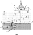
FIG. 1 , offshore andsubsea oil equipments 2 are positioned above a hydrocarbon-bearing and producingzone 3 of a hydrocarbongeological formation 4. The offshore andsubsea oil equipments 2 may comprise a floating vessel orsemisubmersible platform 5 located at the surface and a subsea well equipment 6 located on aseabed level 7.FIG. 1 depicts a well at a stage where it is producing hydrocarbon, e.g. oil and/or gas. The well bore is shown as comprising substantiallyvertical portion 8. However, it may also comprise horizontal or deviated portion (not shown). - Downhole, a producing
section 9 of the well typically comprises perforations, production packers and production tubings at a depth corresponding to the hydrocarbon-bearing and producing zone 3 (i.e. a reservoir of the hydrocarbon geological formation 4). Amultiphase fluid mixture 10 flows out of the hydrocarbon-bearing and producingzone 3, through the producingsection 9, out of the well at theseabed level 7 through the subsea well equipment 6, along theseabed level 7 through a subsea flow line 16, and then towards the surface through a riser/production tubing 11 and then awell head 12. Thewell head 12 is coupled tosurface production arrangement 13 by asurface flow line 14. Thesurface production arrangement 13 may comprise various elements coupled together. For example, thesurface production arrangement 13 comprises a pressure reducer, a pumping arrangement, a separator, a burner, a tank etc... (not shown in details). According to an embodiment, one or more predictive flow assurance assessment system(s) 1 may be coupled at various locations of the flow line between the hydrocarbon-bearing and producingzone 3 and thesurface production arrangement 13. As examples, the predictive flowassurance assessment system 1 may be coupled to theflow line 11 at the level of the subsea well equipment 6, or at the level of thesurface flow line 14, or any other position between theseabed level 7 and the floating vessel orsemisubmersible platform 5. - The
fluid mixture 10 is a multiphase fluid mixture. The terminology "multiphase fluid mixture" has a broad meaning in the oilfield domain of application. It is intended to comprise a broad range of hydrocarbon effluent compositions. Generally, it may be a mixture comprising a plurality of fluid fractions (water, oil, gas) and a plurality of constituting elements (water, various hydrocarbon molecules, impurities, H2S, sand, etc...). In term of fluid fractions, the composition of the mixture may vary in important proportion, for example from heavy oil and high water cut to high gas fraction. It may also be a mixture comprising a single phase in specific conditions, wherein the components constituting said phase may be separated. As examples, such conditions may be above the bubble point, or in non-isobaric or/and non-isothermal conditions. In such conditions, the single phase becomes biphasic and drops heavy components. - The predictive flow
assurance assessment system 1 may be located where or close to a place where, in particular, temperature/pressure may vary to a great extent and where flow issues may occur. In particular, the large temperature and pressure drops from downhole/underground conditions (typical temperatures from 50 to 200°C and pressures up to 2.000 bars) to sea floor conditions (temperatures approximately a few degrees only above 0°C) generates transitions in themultiphase fluid mixture 10. Such conditions may cause flow assurance issues in subsea flow line and surface flow line, for example: - solid compound deposition or precipitation causing a restriction or obstruction of the main flow line. As examples, this may be related to the formation of:
- Hydrates
- Wax or paraffins
- Asphaltenes
- Emulsions
- Scale
- corrosion by a chemically active compound attacking the flow line made of steel materials and causing a leaking of the main flow line. As examples, this may be related to the presence of:
- H2S
- CO2
- solid particles production causing an erosion or plugging of the main flow line. As examples, this may be related to the formation of sand and/or other solid particles that may be present in geological formation; and
- ice formation causing a clogging of the main flow line.
- A
processing arrangement 15 is coupled to the predictive flowassurance assessment system 1. Further, it may also be coupled to other sensors at the surface or subsea or downhole (not shown). Furthermore, it may also be coupled to active completion devices like valves (not shown). Theprocessing arrangement 15 may be positioned at the floating vessel orsemisubmersible platform 5 located at the surface, or, alternatively, in the subsea well equipment 6 at theseabed level 7. Theprocessing arrangement 15 may comprise a computer. It may be managed by an operator located on the floating vessel orsemisubmersible platform 5. It may also be managed at a distance when the floating vessel orsemisubmersible platform 5 is provided with a communication means, e.g. a satellite link (not shown) to transmit data to and receive instructions from an operator's office. Theprocessing arrangement 15 may implement part of the predictive flow assurance assessment method. Theprocessing arrangement 15 may also gather various measurements provided by various sensors related to the hydrocarbon-bearing and producingzone 3 and to themultiphase fluid mixture 10 at various locations of the well. From these measurements, theprocessing arrangement 15 may determine various information related to themultiphase fluid mixture 10, for example the total flow rate, the flow rates of the individual phases of the multiphase fluid mixture, the density of the multiphase fluid mixture, the temperature, the pressure and other parameters. - The precise design of the down-hole producing arrangement and surface production/processing arrangement is not germane to the present invention, and thus these arrangements are not described in details herein.
-
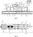
FIG. 2 schematically shows an embodiment of the predictive flowassurance assessment system 1. The predictive flowassurance assessment system 1 comprises afirst measuring module 20, a sampling means 21, amicro-analysis module 22, a discardingmeans 25, a flowissue preventing module 26 and aprocessing module 32. - The
micro-analysis module 22 may comprise aconditioning module 23 and asecond measuring module 24. - The flow
issue preventing module 26 comprises a plurality of injection modules, for example 27A, 27B and 27C, and aheating module 31. Theheating module 31 comprises means for heating the multiphase fluid mixture. Each injection module comprises a container 28 and avalve 29. Each container (for example 28) is filled in with a chemical product (for example 30). As examples, the chemical product filled in the container of theinjection module - product for preventing hydrate formation, e.g. methanol or glycol based products;
- product for preventing asphaltene and paraffin precipitation, e.g. specific solids precipitation inhibitors like ethylene-vinyl acetate copolymer based product;
- product for preventing ice formation, e.g. glycol based product;
- product for adjusting the pH of the multiphase fluid mixture in order to prevent scales formation, e.g. acid or basic product;
- product comprising an anti-caking agent;
- product comprising a corrosion inhibitor; or
- product comprising a solvent; or
- a combination of at least two of the hereinbefore mentioned products.
- The
first measuring module 20 measures at least one actual parameter related to amultiphase fluid mixture 10 flowing in amain flow line first measuring module 20 may comprise a Venturi type multiphase flowmeter that measures pressure, temperature, and total flow rate of the multiphase fluid mixture. It may also be combined with a fraction meter, for example a gamma densitometer. A gamma densitometer comprising a gamma ray source and a gamma ray detector. The gamma densitometer measures absorption of the gamma ray by each phase of the multiphase fluid mixture and estimates a density of the multiphase fluid mixture and a fractional flow rate for each phase. - The sampling means 21 may comprise an inlet port and suction means. As an example, the suction means may be a pump or a Venturi restriction positioned downstream the inlet port so as to induce a suction effect of a
sample part 60 of themultiphase fluid mixture 10 flowing in themain flow line - The
processing module 32 comprises a processor and memory. Theprocessing module 32 is coupled to themicro-analysis module 22, the flowissue preventing module 26 and thefirst measuring module 20. Further, it may be coupled to theprocessing arrangement 15. - The flow
issue preventing module 26 may be placed upstream of the sampling means 21 of themicro-analysis module 22, so that the effect of the flow issue preventing module, e.g. heating or injection of chemical product on the flow conditions may be continuously monitored. Themicro-analysis module 22, the flowissue preventing module 26 and theprocessing module 32 form a feedback loop that enables optimizing the flow issues prevention strategy. -
FIG. 3 schematically shows an embodiment of amicro-analysis module 22 of the predictive flow assurance assessment system embodiment depicted inFIG. 2 . - The
conditioning module 23 may comprise a solid particles filter and anemulsion breaker 40, aphase separator 41, a gas purification membrane 42, an oil purification membrane 43 and a water purification membrane 44. The solid particles filter enables filtering out the sand present in the multiphase fluid mixture sample. The emulsion breaker enables providing an emulsion free multiphase fluid mixture. - The
conditioning module 23 further comprises multiple control parameter modification elements 45, 46 and 47 associated with each phase sample,e.g. gas 61,oil 62 andwater 63, respectively. As an example, the control parameter modification elements 45, 46 or 47 may comprise a Pelletier module or a cooler supplied with sea water in a controlled manner in order to control the temperature of each phase, and/or a pump in order to control the pressure of each phase. - The
second measuring module 24 may comprise: - for analyzing the gas, a hydrogen sulphide H2S sensor 50 and a carbon dioxide CO2 sensor 51;
- for analyzing the oil, a
density D sensor 52, a viscosity vr sensor 53 and aninfrared spectrometer iR 54; and - for analyzing the water, a
pH sensor 55 and a conductivity ρr sensor 56; and - other specific sensors (not shown), for example ultrasonic transducer or optical sensor for detecting ice formation, platinum sonde for measuring temperature, etc...
- The control parameter modification elements 45, 46 or 47 enables modifying at least one control parameter of the
phase sample second measuring module 24 appears. - The predictive flow
assurance assessment system 1 is used to monitor continuously, in real-time or near real-time, and in-situ some properties representative of the actual multiphasefluid mixture 10 flowing in themain flow line -
FIG. 4 schematically illustrates the principle of operation of the embodiment of the predictive flowassurance assessment system 1 depicted inFIGS. 2 and 3 . - In a first step S1, at least one actual parameter related to the
multiphase fluid mixture 10 flowing in themain flow line - In a second step S2, a
fluid sample 60 is taken from themultiphase fluid mixture 10 flowing in themain flow line - In a third step S3, at least one control parameter of the
fluid sample 60 is modified. Such a transition would cause a flow issue when occurring in the main flow line. - In a fourth step S4, the transition of the sample is detected. A corresponding transition value associated with the at least one control parameter is determined accordingly. In case there is not any transition detected (branch N), the step S3 is repeated until a transition appears by successively modifying the at least one control parameter by a given delta (ΔPar).
- In a fifth step S5 (branch Y), a difference between the at least one actual parameter and the at least one transition value is calculated. This difference is representative of a margin relatively to a similar transition appearance in the main flow line causing a flow issue in the
main flow line - Then, in a sixth step S6, the sample is discarded. The sample may be returned back to the
main flow line - In a seventh step S7, it is decided based on the calculated difference compared to a given threshold whether a flow issue preventing step may or may be not implemented. Potential problems of flow issue inside the main flow line are therefore anticipated before they happen and corrective actions can be effectively implemented.
- In case the difference is below the given threshold (branch N), there is not any flow issue preventing step to be implemented. The second step S2 may be implemented once again. Optionally, the second step S2 may be implemented after a given delay. Optionally, the second step S2 may be implemented in a continuous manner.
- In case the difference exceeds the given threshold (branch Y), a flow issue preventing step may be implemented.
- In an eighth step S8, a prevention level may be defined based on the value of said difference, or the nature of control parameter.
- In a ninth step S9, various prevention levels, for example a first level (Level 1), a second level (Level 2), a third level (Level 3), etc... may be implemented based on the control parameter that is actually taken under consideration. As an example, the first level may comprise heating the multiphase fluid mixture, the second level may comprise injecting an appropriate chemical product, and the third level may comprise a combination of the hereinbefore mentioned actions. Other prevention levels may be defined, for example controlling various chokes (not shown) of the installation in order to modify the pressure within the main flow line. This may be implemented through the
processing arrangement 15 at the surface. - Then, the second step S2 is repeated. Thus, the effect of flow issue prevention can be directly monitored. This provides an increased safety margin after the preventing step(s) is(are) implemented. By using this approach, the risks of flow interruption are avoided, at least greatly reduced. Further, the type and quantity of chemical products to be injected are optimized. This results in a very cost effective way of preventing flow issues.
- The drawings and their description hereinbefore illustrate rather than limit the invention.
- It should be appreciated that embodiments of the present invention are not limited to offshore hydrocarbon wells and can also be used with onshore hydrocarbon wells. Furthermore, although some embodiments have drawings showing a vertical well bore, said embodiments may also apply to a horizontal or deviated well bore. All the embodiments of the present invention are equally applicable to cased and uncased borehole (open hole).
- Although a drawing shows different functional entities as different blocks, this by no means excludes implementations in which a single entity carries out several functions, or in which several entities carry out a single function. In this respect, the drawings are very diagrammatic. The functions of the various elements shown in the FIGS., including any functional blocks, may be provided through the use of dedicated hardware as well as hardware capable of executing software in association with appropriate software. When provided by a processor, the functions may be provided by a single dedicated processor, by a single shared processor, or by a plurality of individual processors, some of which may be shared. Moreover, explicit use of the term "entity" should not be construed to refer exclusively to hardware capable of executing software, and may implicitly include, without limitation, digital signal processor (DSP) hardware, processor, application specific integrated circuit (ASIC), field programmable gate array (FPGA), read only memory (ROM) for storing software, random access memory (RAM), and non volatile storage. Other hardware, conventional and/or custom, may also be included.
- It should be appreciated by those skilled in the art that any block diagrams herein represent conceptual views of illustrative elements embodying the principles of the invention. Further, the appended drawings are not intended to be drawn to scale.
- The method and system of the present disclosure may be applied in various industries, for example the oilfield industry, the chemical industry, the aerospace industry, etc...
- Any reference sign in a claim should not be construed as limiting the claim. The word "comprising" does not exclude the presence of other elements than those listed in a claim. The word "a" or "an" preceding an element does not exclude the presence of a plurality of such element.
Claims (13)
- A predictive flow assurance assessment method comprising:- measuring (S1) at least one actual parameter related to a multiphase fluid mixture (10) flowing in a main flow line (11, 14); and- taking (S2) a sample (60) from the multiphase fluid mixture (10) flowing in the main flow line (11, 14);- modifying (S3) at least one control parameter of the sample (60) until a transition appears, wherein said transition would cause a flow issue when occurring in the main flow line (11, 14);- detecting (S4) the transition of the sample (60) and determining a corresponding transition value associated with the at least one control parameter;characterized in that the method further comprises:- calculating (S5) a difference between the at least one actual parameter and the at least one transition value, said difference being representative of a margin relatively to a similar transition appearance in the main flow line causing a flow issue in the main flow line; and- implementing (S8, S9) a flow issue preventing step when the difference exceeds a given threshold (S7).
- The predictive flow assurance assessment method of claim 1, wherein the actual parameter and the control parameter are chosen among the group of parameters comprising a temperature, a pressure, a density, a viscosity, and a quantity of a given compound in the multiphase fluid mixture.
- The predictive flow assurance assessment method of claim 1 or 2, wherein the flow issue in the main flow line (11, 14) is chosen among the group of flow issues comprising a solid compound deposition or precipitation causing a restriction or obstruction of the main flow line, a corrosion by a chemically active compound causing a weakening or a leaking of the main flow line, a solid particles production causing an erosion or plugging of the main flow line, and an ice formation causing a clogging of the main flow line.
- The predictive flow assurance assessment method according to any one of the preceding claims, wherein the flow issue preventing step comprises adjusting the actual parameter related to the multiphase fluid mixture (10) flowing in the main flow line (11, 14) until the difference is not below the given threshold.
- The predictive flow assurance assessment method according to any one of the preceding claims, wherein the flow issue preventing step comprises heating the multiphase fluid mixture (10) flowing in the main flow line (11, 14).
- The predictive flow assurance assessment method according to any one of the preceding claims, wherein the flow issue preventing step comprises injecting a chemical inhibitor product (30) into the multiphase fluid mixture (10) flowing in the main flow line (11, 14).
- A predictive flow assurance assessment system (1) comprising:- a first measuring module (20) to measure at least one actual parameter related to a multiphase fluid mixture (10) flowing in a main flow line (11, 14);- a sampling means (21) to take a sample (60) from the multiphase fluid mixture (10) flowing in the main flow line (11, 14);wherein the system (1) is characterized in that it further comprises:- a conditioning module (23) to modify at least one control parameter of the sample (60) until a transition appears, wherein said transition would cause a flow issue when occurring in the main flow line (11, 14);- a second measuring module (24) to detect the transition of the sample (60) and determining a corresponding transition value associated with the at least one control parameter;- a flow issue preventing module (26) to implement a flow issue preventing step upon reception of a command from a processing module (32);characterized in that the system (1) further comprises:- the processing module (32) arranged to calculate a difference between the at least one actual parameter and the at least one transition value, said difference being representative of a margin relatively to a similar transition appearance in the main flow line (11, 14) causing a flow issue in the main flow line (11, 14).
- The predictive flow assurance assessment system of claim 7, wherein the sampling means (21), the conditioning module (23) and the second measuring module (24) are integrated in a micro-analysis module (22).
- The predictive flow assurance assessment system of claim 7 or 8, wherein the flow issue preventing module (26) comprises a plurality of injection modules (27A, 27B, 27C) and a heating module (31).
- The predictive flow assurance assessment system according to any one of the claims 7 to 9, wherein the flow issue preventing module (26) is positioned upstream of the sampling means (21) of the micro-analysis module (22).
- The predictive flow assurance assessment system according to any one of the claims 7 to 10, wherein the conditioning module (23) comprises a solid particles filter and an emulsion breaker (40), a phase separator (41) for separating at least one phase sample (61, 62, 63) from the multiphase fluid mixture (10), and at least one phase purification membrane (42, 43, 44).
- The predictive flow assurance assessment system according to any one of the claims 7 to 11, wherein the conditioning module (23) comprises at least one control parameter modification element (45, 46, 47) associated with the at least one phase sample (61, 62, 63).
- The predictive flow assurance assessment system according to any one of the claims 7 to 12, wherein the second measuring module (24) comprises at least one sensor chosen among the group of sensors comprising a hydrogen sulphide H2S sensor (50), a carbon dioxide CO2 sensor (51), a density D sensor (52), a viscosity vr sensor (53), an infrared spectrometer iR (54), a pH sensor (55), a conductivity pr sensor (56), an ultrasonic transducer, an optical sensor for detecting ice formation, a platinum sonde for measuring temperature, or a combination of the above.
Priority Applications (4)
| Application Number | Priority Date | Filing Date | Title |
|---|---|---|---|
| EP12305731.7A EP2677115B1 (en) | 2012-06-22 | 2012-06-22 | A predictive flow assurance assessment method and system |
| MX2013006977A MX354804B (en) | 2012-06-22 | 2013-06-18 | Density and viscosity sensor and measuring method. |
| US14/410,043 US9777555B2 (en) | 2012-06-22 | 2013-06-21 | Predictive flow assurance assessment method and system |
| PCT/EP2013/063000 WO2013190093A2 (en) | 2012-06-22 | 2013-06-21 | A predictive flow assurance assessment method and system |
Applications Claiming Priority (1)
| Application Number | Priority Date | Filing Date | Title |
|---|---|---|---|
| EP12305731.7A EP2677115B1 (en) | 2012-06-22 | 2012-06-22 | A predictive flow assurance assessment method and system |
Publications (2)
| Publication Number | Publication Date |
|---|---|
| EP2677115A1 EP2677115A1 (en) | 2013-12-25 |
| EP2677115B1 true EP2677115B1 (en) | 2019-01-02 |
Family
ID=48746448
Family Applications (1)
| Application Number | Title | Priority Date | Filing Date |
|---|---|---|---|
| EP12305731.7A Active EP2677115B1 (en) | 2012-06-22 | 2012-06-22 | A predictive flow assurance assessment method and system |
Country Status (4)
| Country | Link |
|---|---|
| US (1) | US9777555B2 (en) |
| EP (1) | EP2677115B1 (en) |
| MX (1) | MX354804B (en) |
| WO (1) | WO2013190093A2 (en) |
Families Citing this family (15)
| Publication number | Priority date | Publication date | Assignee | Title |
|---|---|---|---|---|
| WO2014205395A1 (en) | 2013-06-20 | 2014-12-24 | The Regents Of The University Of Michigan | Microdischarge-based transducer |
| WO2015069164A1 (en) * | 2013-11-08 | 2015-05-14 | Telefonaktiebolaget L M Ericsson (Publ) | Handling of transport conditions |
| WO2015142949A1 (en) | 2014-03-17 | 2015-09-24 | The Regents Of The University Of Michigan | Packaged microsystems |
| WO2016014796A2 (en) | 2014-07-23 | 2016-01-28 | Baker Hughes Incorporated | System and method for downhole inorganic scale monitoring and intervention in a production well |
| BR112017001353B1 (en) | 2014-07-23 | 2022-02-22 | Baker Hughes Incorporated | Apparatus and method for monitoring downhole organic scale and intervening in a production well |
| WO2016067222A1 (en) * | 2014-10-28 | 2016-05-06 | Onesubsea Ip Uk Limited | Additive management system |
| US9562430B1 (en) | 2015-10-05 | 2017-02-07 | Baker Hughes Incorporated | Chemiresistive sensors for downhole tools |
| US10983499B2 (en) | 2016-04-20 | 2021-04-20 | Baker Hughes, A Ge Company, Llc | Drilling fluid pH monitoring and control |
| US20190003290A1 (en) * | 2017-07-03 | 2019-01-03 | Exmar Offshore Company | Techniques for improved oil recovery |
| CN109025906A (en) * | 2018-08-02 | 2018-12-18 | 中国石油天然气股份有限公司 | A kind of quantitative dosing case and a kind of quantitative dosing vehicle |
| GB201907388D0 (en) * | 2019-05-24 | 2019-07-10 | Resman As | Method and apparatus for quantitative multi-phase downhole surveillance |
| US11885219B2 (en) | 2020-03-23 | 2024-01-30 | Cameron International Corporation | Chemical injection system for a resource extraction system |
| CN111737914B (en) * | 2020-06-16 | 2023-10-24 | 中国石油天然气股份有限公司 | Method and device for measuring water mixing flow of oil well, electronic equipment and storage medium |
| US20220003083A1 (en) * | 2020-07-01 | 2022-01-06 | Baker Hughes Oilfield Operations Llc | Filtration of fluids using conformable porous shape memory media |
| WO2022081533A1 (en) * | 2020-10-14 | 2022-04-21 | Cameron International Corporation | Real-time scale precipitation prediction and control systems and methods |
Family Cites Families (5)
| Publication number | Priority date | Publication date | Assignee | Title |
|---|---|---|---|---|
| SU1308995A1 (en) * | 1985-12-17 | 1987-05-07 | Специальное проектно-конструкторское бюро "Промавтоматика" | Device for introducing hydrate generation inhibitor in gas flow |
| US5016712A (en) * | 1990-03-06 | 1991-05-21 | Mobil Oil Corporation | Method and apparatus for locating solvent injection apparatus within a natural gas wellbore |
| FR2737279B1 (en) | 1995-07-27 | 1997-09-19 | Inst Francais Du Petrole | SYSTEM AND METHOD FOR TRANSPORTING A FLUID LIKELY TO FORM HYDRATES |
| EP2075403B1 (en) | 2007-12-27 | 2010-12-15 | PRAD Research and Development N.V. | Real-time measurement of reservoir fluid properties |
| GB2460668B (en) * | 2008-06-04 | 2012-08-01 | Schlumberger Holdings | Subsea fluid sampling and analysis |
-
2012
- 2012-06-22 EP EP12305731.7A patent/EP2677115B1/en active Active
-
2013
- 2013-06-18 MX MX2013006977A patent/MX354804B/en active IP Right Grant
- 2013-06-21 WO PCT/EP2013/063000 patent/WO2013190093A2/en active Application Filing
- 2013-06-21 US US14/410,043 patent/US9777555B2/en active Active
Non-Patent Citations (1)
| Title |
|---|
| None * |
Also Published As
| Publication number | Publication date |
|---|---|
| US20160186533A1 (en) | 2016-06-30 |
| MX2013006977A (en) | 2013-12-23 |
| US9777555B2 (en) | 2017-10-03 |
| WO2013190093A3 (en) | 2014-06-19 |
| MX354804B (en) | 2018-03-22 |
| WO2013190093A2 (en) | 2013-12-27 |
| EP2677115A1 (en) | 2013-12-25 |
Similar Documents
| Publication | Publication Date | Title |
|---|---|---|
| EP2677115B1 (en) | A predictive flow assurance assessment method and system | |
| US9347310B2 (en) | Multiphase flowmeter for subsea applications | |
| EP2446116B1 (en) | Apparatus and method for detecting and quantifying leakage in a pipe | |
| Sakurai et al. | Issues and challenges with controlling large drawdown in the first offshore methane-hydrate production test | |
| CA2874592C (en) | Dual differential pressure multiphase flow meter | |
| EP3365528B1 (en) | Method and system for determining the production rate of fluids in a gas well | |
| US11504648B2 (en) | Well clean-up monitoring technique | |
| Cayeux et al. | Precise gain and loss detection using a transient hydraulic model of the return flow to the pit | |
| US10989039B2 (en) | Production of hydrocarbons with test separator | |
| CN103926422A (en) | Fluid measuring system and method | |
| EP1828727B1 (en) | Method for determining a phase volume of a multiphase fluid in a pipeline by the help of a tracer | |
| US20180051549A1 (en) | Erosion management system | |
| NO20201135A1 (en) | Improved flow measurement | |
| Shumakov et al. | Five Years' Experience Using Coriolis Separators in North Sea Well Testing | |
| Vielliard et al. | Real-Time Subsea Hydrate Management in the World's Longest Subsea Tieback | |
| WO2020263098A1 (en) | Optimisation of water injection for liquid hydrocarbon production | |
| Abili et al. | Synergy of fluid sampling and subsea processing, key to maximising offshore asset recovery | |
| US11885219B2 (en) | Chemical injection system for a resource extraction system | |
| US11512557B2 (en) | Integrated system and method for automated monitoring and control of sand-prone well | |
| Tosic et al. | Multiphase well-rate measurements applied to reservoir analysis | |
| Tonkonog et al. | Experience of Application of Different Multiphase Metering Technologies for Cold Production and High Viscosity Oil Systems | |
| Hall | Subsea liquid sampling using flow-through technique | |
| NO20230258A1 (en) | Water detection and measurement system and method | |
| Dujardin et al. | New Methodology to Calculate Water Cut in Mature Waterflood-Alba Field |
Legal Events
| Date | Code | Title | Description |
|---|---|---|---|
| PUAI | Public reference made under article 153(3) epc to a published international application that has entered the european phase |
Free format text: ORIGINAL CODE: 0009012 |
|
| AK | Designated contracting states |
Kind code of ref document: A1 Designated state(s): AL AT BE BG CH CY CZ DE DK EE ES FI FR GB GR HR HU IE IS IT LI LT LU LV MC MK MT NL NO PL PT RO RS SE SI SK SM TR |
|
| AX | Request for extension of the european patent |
Extension state: BA ME |
|
| 17P | Request for examination filed |
Effective date: 20140625 |
|
| RBV | Designated contracting states (corrected) |
Designated state(s): AL AT BE BG CH CY CZ DE DK EE ES FI FR GB GR HR HU IE IS IT LI LT LU LV MC MK MT NL NO PL PT RO RS SE SI SK SM TR |
|
| GRAP | Despatch of communication of intention to grant a patent |
Free format text: ORIGINAL CODE: EPIDOSNIGR1 |
|
| STAA | Information on the status of an ep patent application or granted ep patent |
Free format text: STATUS: GRANT OF PATENT IS INTENDED |
|
| INTG | Intention to grant announced |
Effective date: 20180718 |
|
| GRAS | Grant fee paid |
Free format text: ORIGINAL CODE: EPIDOSNIGR3 |
|
| GRAA | (expected) grant |
Free format text: ORIGINAL CODE: 0009210 |
|
| STAA | Information on the status of an ep patent application or granted ep patent |
Free format text: STATUS: THE PATENT HAS BEEN GRANTED |
|
| AK | Designated contracting states |
Kind code of ref document: B1 Designated state(s): AL AT BE BG CH CY CZ DE DK EE ES FI FR GB GR HR HU IE IS IT LI LT LU LV MC MK MT NL NO PL PT RO RS SE SI SK SM TR |
|
| REG | Reference to a national code |
Ref country code: GB Ref legal event code: FG4D |
|
| REG | Reference to a national code |
Ref country code: CH Ref legal event code: EP Ref country code: AT Ref legal event code: REF Ref document number: 1084613 Country of ref document: AT Kind code of ref document: T Effective date: 20190115 |
|
| REG | Reference to a national code |
Ref country code: IE Ref legal event code: FG4D |
|
| REG | Reference to a national code |
Ref country code: DE Ref legal event code: R096 Ref document number: 602012055378 Country of ref document: DE |
|
| REG | Reference to a national code |
Ref country code: NO Ref legal event code: T2 Effective date: 20190102 |
|
| REG | Reference to a national code |
Ref country code: NL Ref legal event code: MP Effective date: 20190102 |
|
| REG | Reference to a national code |
Ref country code: LT Ref legal event code: MG4D |
|
| REG | Reference to a national code |
Ref country code: AT Ref legal event code: MK05 Ref document number: 1084613 Country of ref document: AT Kind code of ref document: T Effective date: 20190102 |
|
| PG25 | Lapsed in a contracting state [announced via postgrant information from national office to epo] |
Ref country code: NL Free format text: LAPSE BECAUSE OF FAILURE TO SUBMIT A TRANSLATION OF THE DESCRIPTION OR TO PAY THE FEE WITHIN THE PRESCRIBED TIME-LIMIT Effective date: 20190102 |
|
| PG25 | Lapsed in a contracting state [announced via postgrant information from national office to epo] |
Ref country code: PT Free format text: LAPSE BECAUSE OF FAILURE TO SUBMIT A TRANSLATION OF THE DESCRIPTION OR TO PAY THE FEE WITHIN THE PRESCRIBED TIME-LIMIT Effective date: 20190502 Ref country code: ES Free format text: LAPSE BECAUSE OF FAILURE TO SUBMIT A TRANSLATION OF THE DESCRIPTION OR TO PAY THE FEE WITHIN THE PRESCRIBED TIME-LIMIT Effective date: 20190102 Ref country code: SE Free format text: LAPSE BECAUSE OF FAILURE TO SUBMIT A TRANSLATION OF THE DESCRIPTION OR TO PAY THE FEE WITHIN THE PRESCRIBED TIME-LIMIT Effective date: 20190102 Ref country code: FI Free format text: LAPSE BECAUSE OF FAILURE TO SUBMIT A TRANSLATION OF THE DESCRIPTION OR TO PAY THE FEE WITHIN THE PRESCRIBED TIME-LIMIT Effective date: 20190102 Ref country code: PL Free format text: LAPSE BECAUSE OF FAILURE TO SUBMIT A TRANSLATION OF THE DESCRIPTION OR TO PAY THE FEE WITHIN THE PRESCRIBED TIME-LIMIT Effective date: 20190102 Ref country code: LT Free format text: LAPSE BECAUSE OF FAILURE TO SUBMIT A TRANSLATION OF THE DESCRIPTION OR TO PAY THE FEE WITHIN THE PRESCRIBED TIME-LIMIT Effective date: 20190102 |
|
| PG25 | Lapsed in a contracting state [announced via postgrant information from national office to epo] |
Ref country code: BG Free format text: LAPSE BECAUSE OF FAILURE TO SUBMIT A TRANSLATION OF THE DESCRIPTION OR TO PAY THE FEE WITHIN THE PRESCRIBED TIME-LIMIT Effective date: 20190402 Ref country code: GR Free format text: LAPSE BECAUSE OF FAILURE TO SUBMIT A TRANSLATION OF THE DESCRIPTION OR TO PAY THE FEE WITHIN THE PRESCRIBED TIME-LIMIT Effective date: 20190403 Ref country code: IS Free format text: LAPSE BECAUSE OF FAILURE TO SUBMIT A TRANSLATION OF THE DESCRIPTION OR TO PAY THE FEE WITHIN THE PRESCRIBED TIME-LIMIT Effective date: 20190502 Ref country code: HR Free format text: LAPSE BECAUSE OF FAILURE TO SUBMIT A TRANSLATION OF THE DESCRIPTION OR TO PAY THE FEE WITHIN THE PRESCRIBED TIME-LIMIT Effective date: 20190102 Ref country code: LV Free format text: LAPSE BECAUSE OF FAILURE TO SUBMIT A TRANSLATION OF THE DESCRIPTION OR TO PAY THE FEE WITHIN THE PRESCRIBED TIME-LIMIT Effective date: 20190102 Ref country code: RS Free format text: LAPSE BECAUSE OF FAILURE TO SUBMIT A TRANSLATION OF THE DESCRIPTION OR TO PAY THE FEE WITHIN THE PRESCRIBED TIME-LIMIT Effective date: 20190102 |
|
| REG | Reference to a national code |
Ref country code: DE Ref legal event code: R097 Ref document number: 602012055378 Country of ref document: DE |
|
| PG25 | Lapsed in a contracting state [announced via postgrant information from national office to epo] |
Ref country code: RO Free format text: LAPSE BECAUSE OF FAILURE TO SUBMIT A TRANSLATION OF THE DESCRIPTION OR TO PAY THE FEE WITHIN THE PRESCRIBED TIME-LIMIT Effective date: 20190102 Ref country code: IT Free format text: LAPSE BECAUSE OF FAILURE TO SUBMIT A TRANSLATION OF THE DESCRIPTION OR TO PAY THE FEE WITHIN THE PRESCRIBED TIME-LIMIT Effective date: 20190102 Ref country code: CZ Free format text: LAPSE BECAUSE OF FAILURE TO SUBMIT A TRANSLATION OF THE DESCRIPTION OR TO PAY THE FEE WITHIN THE PRESCRIBED TIME-LIMIT Effective date: 20190102 Ref country code: EE Free format text: LAPSE BECAUSE OF FAILURE TO SUBMIT A TRANSLATION OF THE DESCRIPTION OR TO PAY THE FEE WITHIN THE PRESCRIBED TIME-LIMIT Effective date: 20190102 Ref country code: AT Free format text: LAPSE BECAUSE OF FAILURE TO SUBMIT A TRANSLATION OF THE DESCRIPTION OR TO PAY THE FEE WITHIN THE PRESCRIBED TIME-LIMIT Effective date: 20190102 Ref country code: DK Free format text: LAPSE BECAUSE OF FAILURE TO SUBMIT A TRANSLATION OF THE DESCRIPTION OR TO PAY THE FEE WITHIN THE PRESCRIBED TIME-LIMIT Effective date: 20190102 Ref country code: AL Free format text: LAPSE BECAUSE OF FAILURE TO SUBMIT A TRANSLATION OF THE DESCRIPTION OR TO PAY THE FEE WITHIN THE PRESCRIBED TIME-LIMIT Effective date: 20190102 Ref country code: SK Free format text: LAPSE BECAUSE OF FAILURE TO SUBMIT A TRANSLATION OF THE DESCRIPTION OR TO PAY THE FEE WITHIN THE PRESCRIBED TIME-LIMIT Effective date: 20190102 |
|
| PLBE | No opposition filed within time limit |
Free format text: ORIGINAL CODE: 0009261 |
|
| STAA | Information on the status of an ep patent application or granted ep patent |
Free format text: STATUS: NO OPPOSITION FILED WITHIN TIME LIMIT |
|
| PG25 | Lapsed in a contracting state [announced via postgrant information from national office to epo] |
Ref country code: SM Free format text: LAPSE BECAUSE OF FAILURE TO SUBMIT A TRANSLATION OF THE DESCRIPTION OR TO PAY THE FEE WITHIN THE PRESCRIBED TIME-LIMIT Effective date: 20190102 |
|
| 26N | No opposition filed |
Effective date: 20191003 |
|
| REG | Reference to a national code |
Ref country code: DE Ref legal event code: R119 Ref document number: 602012055378 Country of ref document: DE |
|
| PG25 | Lapsed in a contracting state [announced via postgrant information from national office to epo] |
Ref country code: MC Free format text: LAPSE BECAUSE OF FAILURE TO SUBMIT A TRANSLATION OF THE DESCRIPTION OR TO PAY THE FEE WITHIN THE PRESCRIBED TIME-LIMIT Effective date: 20190102 |
|
| REG | Reference to a national code |
Ref country code: CH Ref legal event code: PL |
|
| PG25 | Lapsed in a contracting state [announced via postgrant information from national office to epo] |
Ref country code: SI Free format text: LAPSE BECAUSE OF FAILURE TO SUBMIT A TRANSLATION OF THE DESCRIPTION OR TO PAY THE FEE WITHIN THE PRESCRIBED TIME-LIMIT Effective date: 20190102 |
|
| REG | Reference to a national code |
Ref country code: BE Ref legal event code: MM Effective date: 20190630 |
|
| PG25 | Lapsed in a contracting state [announced via postgrant information from national office to epo] |
Ref country code: TR Free format text: LAPSE BECAUSE OF FAILURE TO SUBMIT A TRANSLATION OF THE DESCRIPTION OR TO PAY THE FEE WITHIN THE PRESCRIBED TIME-LIMIT Effective date: 20190102 |
|
| PG25 | Lapsed in a contracting state [announced via postgrant information from national office to epo] |
Ref country code: IE Free format text: LAPSE BECAUSE OF NON-PAYMENT OF DUE FEES Effective date: 20190622 Ref country code: DE Free format text: LAPSE BECAUSE OF NON-PAYMENT OF DUE FEES Effective date: 20200101 |
|
| PG25 | Lapsed in a contracting state [announced via postgrant information from national office to epo] |
Ref country code: LU Free format text: LAPSE BECAUSE OF NON-PAYMENT OF DUE FEES Effective date: 20190622 Ref country code: BE Free format text: LAPSE BECAUSE OF NON-PAYMENT OF DUE FEES Effective date: 20190630 Ref country code: CH Free format text: LAPSE BECAUSE OF NON-PAYMENT OF DUE FEES Effective date: 20190630 Ref country code: LI Free format text: LAPSE BECAUSE OF NON-PAYMENT OF DUE FEES Effective date: 20190630 |
|
| PG25 | Lapsed in a contracting state [announced via postgrant information from national office to epo] |
Ref country code: CY Free format text: LAPSE BECAUSE OF FAILURE TO SUBMIT A TRANSLATION OF THE DESCRIPTION OR TO PAY THE FEE WITHIN THE PRESCRIBED TIME-LIMIT Effective date: 20190102 |
|
| PG25 | Lapsed in a contracting state [announced via postgrant information from national office to epo] |
Ref country code: HU Free format text: LAPSE BECAUSE OF FAILURE TO SUBMIT A TRANSLATION OF THE DESCRIPTION OR TO PAY THE FEE WITHIN THE PRESCRIBED TIME-LIMIT; INVALID AB INITIO Effective date: 20120622 Ref country code: MT Free format text: LAPSE BECAUSE OF FAILURE TO SUBMIT A TRANSLATION OF THE DESCRIPTION OR TO PAY THE FEE WITHIN THE PRESCRIBED TIME-LIMIT Effective date: 20190102 |
|
| PG25 | Lapsed in a contracting state [announced via postgrant information from national office to epo] |
Ref country code: MK Free format text: LAPSE BECAUSE OF FAILURE TO SUBMIT A TRANSLATION OF THE DESCRIPTION OR TO PAY THE FEE WITHIN THE PRESCRIBED TIME-LIMIT Effective date: 20190102 |
|
| PGFP | Annual fee paid to national office [announced via postgrant information from national office to epo] |
Ref country code: NO Payment date: 20230519 Year of fee payment: 12 Ref country code: FR Payment date: 20230515 Year of fee payment: 12 |
|
| PGFP | Annual fee paid to national office [announced via postgrant information from national office to epo] |
Ref country code: GB Payment date: 20230515 Year of fee payment: 12 |