EP2671156B1 - Diagnostic information logging - Google Patents
Diagnostic information logging Download PDFInfo
- Publication number
- EP2671156B1 EP2671156B1 EP12702638.3A EP12702638A EP2671156B1 EP 2671156 B1 EP2671156 B1 EP 2671156B1 EP 12702638 A EP12702638 A EP 12702638A EP 2671156 B1 EP2671156 B1 EP 2671156B1
- Authority
- EP
- European Patent Office
- Prior art keywords
- logging
- mode
- diagnostic information
- controller
- router
- Prior art date
- Legal status (The legal status is an assumption and is not a legal conclusion. Google has not performed a legal analysis and makes no representation as to the accuracy of the status listed.)
- Active
Links
- 230000008439 repair process Effects 0.000 claims description 41
- 238000000034 method Methods 0.000 claims description 36
- 238000004891 communication Methods 0.000 claims description 26
- 230000004044 response Effects 0.000 claims description 16
- 230000004075 alteration Effects 0.000 claims description 7
- 230000006870 function Effects 0.000 description 9
- 238000010586 diagram Methods 0.000 description 8
- 230000008901 benefit Effects 0.000 description 3
- 230000008014 freezing Effects 0.000 description 3
- 238000007710 freezing Methods 0.000 description 3
- 230000002085 persistent effect Effects 0.000 description 3
- 238000013024 troubleshooting Methods 0.000 description 3
- 238000004458 analytical method Methods 0.000 description 2
- 230000000295 complement effect Effects 0.000 description 2
- 238000007726 management method Methods 0.000 description 2
- 238000012545 processing Methods 0.000 description 2
- VOWAEIGWURALJQ-UHFFFAOYSA-N Dicyclohexyl phthalate Chemical compound C=1C=CC=C(C(=O)OC2CCCCC2)C=1C(=O)OC1CCCCC1 VOWAEIGWURALJQ-UHFFFAOYSA-N 0.000 description 1
- 230000009471 action Effects 0.000 description 1
- 230000005540 biological transmission Effects 0.000 description 1
- 230000003247 decreasing effect Effects 0.000 description 1
- 238000013461 design Methods 0.000 description 1
- 238000001514 detection method Methods 0.000 description 1
- 238000005516 engineering process Methods 0.000 description 1
- 238000004374 forensic analysis Methods 0.000 description 1
- 238000009434 installation Methods 0.000 description 1
- 230000003993 interaction Effects 0.000 description 1
- 230000002452 interceptive effect Effects 0.000 description 1
- 230000014759 maintenance of location Effects 0.000 description 1
- 230000004048 modification Effects 0.000 description 1
- 238000012986 modification Methods 0.000 description 1
- 230000008569 process Effects 0.000 description 1
- 230000007704 transition Effects 0.000 description 1
Images

Classifications
-
- H—ELECTRICITY
- H04—ELECTRIC COMMUNICATION TECHNIQUE
- H04L—TRANSMISSION OF DIGITAL INFORMATION, e.g. TELEGRAPHIC COMMUNICATION
- H04L49/00—Packet switching elements
- H04L49/55—Prevention, detection or correction of errors
- H04L49/557—Error correction, e.g. fault recovery or fault tolerance
-
- H—ELECTRICITY
- H04—ELECTRIC COMMUNICATION TECHNIQUE
- H04L—TRANSMISSION OF DIGITAL INFORMATION, e.g. TELEGRAPHIC COMMUNICATION
- H04L41/00—Arrangements for maintenance, administration or management of data switching networks, e.g. of packet switching networks
- H04L41/08—Configuration management of networks or network elements
- H04L41/0803—Configuration setting
- H04L41/0813—Configuration setting characterised by the conditions triggering a change of settings
-
- G—PHYSICS
- G06—COMPUTING; CALCULATING OR COUNTING
- G06F—ELECTRIC DIGITAL DATA PROCESSING
- G06F11/00—Error detection; Error correction; Monitoring
- G06F11/07—Responding to the occurrence of a fault, e.g. fault tolerance
- G06F11/0703—Error or fault processing not based on redundancy, i.e. by taking additional measures to deal with the error or fault not making use of redundancy in operation, in hardware, or in data representation
- G06F11/0766—Error or fault reporting or storing
- G06F11/0781—Error filtering or prioritizing based on a policy defined by the user or on a policy defined by a hardware/software module, e.g. according to a severity level
-
- G—PHYSICS
- G06—COMPUTING; CALCULATING OR COUNTING
- G06F—ELECTRIC DIGITAL DATA PROCESSING
- G06F11/00—Error detection; Error correction; Monitoring
- G06F11/30—Monitoring
- G06F11/34—Recording or statistical evaluation of computer activity, e.g. of down time, of input/output operation ; Recording or statistical evaluation of user activity, e.g. usability assessment
- G06F11/3466—Performance evaluation by tracing or monitoring
- G06F11/3476—Data logging
-
- H—ELECTRICITY
- H04—ELECTRIC COMMUNICATION TECHNIQUE
- H04L—TRANSMISSION OF DIGITAL INFORMATION, e.g. TELEGRAPHIC COMMUNICATION
- H04L41/00—Arrangements for maintenance, administration or management of data switching networks, e.g. of packet switching networks
- H04L41/06—Management of faults, events, alarms or notifications
- H04L41/069—Management of faults, events, alarms or notifications using logs of notifications; Post-processing of notifications
-
- H—ELECTRICITY
- H04—ELECTRIC COMMUNICATION TECHNIQUE
- H04L—TRANSMISSION OF DIGITAL INFORMATION, e.g. TELEGRAPHIC COMMUNICATION
- H04L63/00—Network architectures or network communication protocols for network security
- H04L63/14—Network architectures or network communication protocols for network security for detecting or protecting against malicious traffic
- H04L63/1408—Network architectures or network communication protocols for network security for detecting or protecting against malicious traffic by monitoring network traffic
- H04L63/1425—Traffic logging, e.g. anomaly detection
-
- H—ELECTRICITY
- H04—ELECTRIC COMMUNICATION TECHNIQUE
- H04L—TRANSMISSION OF DIGITAL INFORMATION, e.g. TELEGRAPHIC COMMUNICATION
- H04L41/00—Arrangements for maintenance, administration or management of data switching networks, e.g. of packet switching networks
- H04L41/06—Management of faults, events, alarms or notifications
- H04L41/0681—Configuration of triggering conditions
-
- H—ELECTRICITY
- H04—ELECTRIC COMMUNICATION TECHNIQUE
- H04L—TRANSMISSION OF DIGITAL INFORMATION, e.g. TELEGRAPHIC COMMUNICATION
- H04L61/00—Network arrangements, protocols or services for addressing or naming
- H04L61/50—Address allocation
- H04L61/5007—Internet protocol [IP] addresses
- H04L61/5014—Internet protocol [IP] addresses using dynamic host configuration protocol [DHCP] or bootstrap protocol [BOOTP]
Definitions
- the present invention generally relates to logging diagnostic information, and, more particularly, to logging systems, methods and devices for routers and similar computing devices.
- Routers have implemented a variety of logging methods to enable compiling and retention of diagnostic information.
- US2007/067675A1 discloses managing data related to the failure of a device, comprising storing logging data and providing them to a human operator for analysis.
- US2002/198983A1 discloses a system providing a multiple level logging system having a first level for detecting message level errors and a second trace level for obtaining trace information to provide more details to be used for implementing corrective action. The frequency of logging can be adjusted upward in response to detection of an error and can then be decreased. For example, a physically separate non-volatile RAM (random access memory) that is separate from the main flash memory has been maintained in such routers for logging.
- random access memory random access memory
- the separate memory is used in this case to avoid wearing out the main non-volatile RAM.
- Other methods simply assume that the flash memory will not wear out in the lifetime of the product.
- an excessive amount of logging as can be induced by a problem in the router, can render the lifetime estimate inaccurate and can prematurely cause failure of the memory of an electronic device.
- One embodiment is directed to a method.
- first diagnostic information is logged in a router in accordance with a first mode having a first logging rate.
- an operational problem within the router is detected.
- second diagnostic information is logged in accordance with a second mode having a second logging rate that is greater than the first logging rate of the first mode.
- An alternative embodiment is directed to an operational router apparatus that includes a communication interface and a controller.
- the controller configured to log first diagnostic information in a router in accordance with a first mode and to detect an operational problem within the router.
- the communication interface is configured to transmit an indication of the operational problem and to remotely receive instructions to log second diagnostic information in the router in accordance with a second mode.
- the controller is further configured to log the second diagnostic information in accordance with the second mode in response to receipt of the instructions.
- the second diagnostic information is composed of a larger amount of data than the first diagnostic information.
- Another embodiment is directed to a system that includes a communication interface and a controller.
- the communication interface is configured to remotely receive an indication of an operational problem at a router.
- the controller is configured to direct the communication interface to transmit instructions to the router that direct the router to switch a logging mode from a first mode to a second mode.
- First diagnostic information is logged at the router in accordance with the first mode and second diagnostic information is logged at the router in accordance with the second mode.
- the second diagnostic information is composed of a larger amount of data than the first diagnostic
- Embodiments relate only to claimed combinations of features.
- the term “embodiment” relates to unclaimed combinations of features, said term has to be understood as referring to examples of the present invention.
- the present principles are directed to methods, systems and apparatuses for logging diagnostic information.
- multiple logging modes can be employed to log diagnostic information in a way that minimally affects the service life of the memory used to store the logs and that maintains effectiveness of the logs in enabling repairs of the system.
- the logging can be switched to a more comprehensive mode in response to detecting certain problems in the system, such as freezing and unexpected rebooting.
- the logging mode can be altered so that more relevant or different information is logged.
- the logging mode can be altered such that the logging rate is increased and/or the maximum number of writes is changed in response to detecting a problem.
- the logging mode alteration can be directed remotely at a vendor technical support site in response to receiving an indication that a problem has been detected by the system or by a user of the system.
- This feature enables the vendor to retain proprietary control of system settings and thereby ensure that the life of the system is not prematurely shortened by the user.
- the remote settings of the logging modes can be monitored and can be compared to system models to ensure that the system has at least a minimum service life in accordance with system specifications provided by the vendor to users.
- processor or “controller” should not be construed to refer exclusively to hardware capable of executing software, and can implicitly include, without limitation, digital signal processor ("DSP") hardware and also computer readable storage mediums for storing software, such as read-only memory (“ROM”), random access memory (“RAM”), and non-volatile storage.
- DSP digital signal processor
- any switches shown in the figures are conceptual only. Their function can be carried out through the operation of program logic, through dedicated logic, through the interaction of program control and dedicated logic, or even manually, the particular technique being selectable by the implementer as more specifically understood from the context.
- any element expressed as a means for performing a specified function is intended to encompass any way of performing that function including, for example, a) a combination of circuit elements that performs that function or b) software in any form, including, therefore, firmware, microcode or the like, combined with appropriate circuitry for executing that software to perform the function.
- the present principles as defined by such claims reside in the fact that the functionalities provided by the various recited means are combined and brought together in the manner which the claims call for. It is thus regarded that any means that can provide those functionalities are equivalent to those shown herein.
- such phrasing is intended to encompass the selection of the first listed option (A) only, or the selection of the second listed option (B) only, or the selection of the third listed option (C) only, or the selection of the first and the second listed options (A and B) only, or the selection of the first and third listed options (A and C) only, or the selection of the second and third listed options (B and C) only, or the selection of all three options (A and B and C).
- This can be extended, as readily apparent by one of ordinary skill in this and related arts, for as many items listed.
- the logging of events is very important for certain equipment, such as a broadband home router (BHR) and the like, because the logging records the past and present state of the device and aids in troubleshooting any problems that a consumer might have with the device.
- Logging is utilized to record events to enable the determination of sources of failure as well as proper operation and to identify hacking threats. If the information is logged in only volatile memory and the device reboots because of an operational problem, then the logging information can be lost at a time when it is most crucial to record. As a result, the main flash memory has been used to store such information.
- a logging system the purpose of a logging system is to enable the performance of a forensic analysis of a problem and to enable the use of this information to correct it.
- a problem causes a reboot and the logs are stored in volatile memory, then the logs can be lost.
- the number of times in normal operation that a freeze/reboot occurs can be a relatively small number, and much of the logging (and attendant writing to the flash memory) would be wasted.
- the device can maintain the ability to assist in diagnosing issues, while still maintaining a long life.
- a new logging scheme which is referred to herein as "persistent logging," can be utilized based on a set of conditions that exist in an electronic device, such as a BHR, itself.
- logging information is stored in an electronic device's non-volatile memory only for repair/debugging purposes, thereby greatly reducing the number of writes to the memory.
- the logging system is particularly efficient when electronic memory is used.
- the electronic device e.g., BHR
- BHR records a minimal amount of information, and limits itself to no more than one write every N1 minutes.
- the actual times can be decided based on operational factors. This is designated as a "Level 1" condition; the minimum information in this case corresponds to relevant information gathered since the most recent reboot time.
- Such information can be related to connectivity issues in accordance with DHCP (dynamic host control protocol) or PPPoE (Point to Point Protocol over Ethernet), and is not be gathered very often.
- DHCP dynamic host control protocol
- PPPoE Point to Point Protocol over Ethernet
- a "Level 2" condition permits writes every N2 minutes, where N2 is less than N1, and can prompt the device to generate one or more of the following logs: firewall logs, LAN (local area network) DHCP transactions, interface settings logs, IGMP (Internet Gateway Management Protocol) logs, as well as other logs as appropriate or specified by an administrator.
- Operational factors that can be considered to set "N1" and “N2" can include the number of writes available to the memory, the estimated number of writes per second and the operational life of the product. For the “N1" range, it is estimated that once per hour would be sufficient, while “N2" can be as high as once per second. However, the values can be varied based on the operational factors.
- Level 1 and Level 2 Flags, as well as N1 and N2, in the device can be remotely settable, using, for example, TR-069 (CPE (Customer Premises Equipment) WAN (Wide Area Network) Management Protocol) vendor extensions.
- CPE Customer Premises Equipment
- WAN Wide Area Network
- M1 and M2 can be set so that persistent logging does not overwhelm the flash space in the event that a debugging/repair process was inadvertently left running.
- M1 can be set to 1 kilobyte per hour
- M2 can be set to a rate as high as 1 megabyte per hour.
- logs stored in main memory can be consulted primarily in the event that a router has a problem, where freezing/rebooting is not an issue.
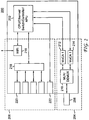
- the system 100 can include a technical support system 101 and a router system 121 that communicate through a wide area network 110, such as the internet, which can be wired or wireless or can include both wired and wireless components. It should be noted that although features of the present principles are described herein with respect to a router system 121, in accordance with alternative embodiments, the system 121 can be any other appropriate computing system.
- the router system 121 can include a controller 122, a communication interface 126, a network interface 128 and a storage medium 124.
- the technical support system 101 can include a controller 102, a communication interface 106, a repair module 108 and a storage medium 104. The functions of the various elements of the system 100 are described in more detail herein below with respect to specific apparatus and method embodiments.
- the system 200 is a broadband home router and can include a controller element 202, which can comprise a central processing unit (CPU), an Ethernet switch, a network processing unit (NPU) and a storage medium.
- the controller element 202 is one exemplary implementation of the controller 122 and the storage medium 124.
- the system 200 can further include a communication interface 204 and a network interface 206, which are exemplary implementations of the communication interface 126 and the network interface 128, respectively.
- the communication interface 204 can include a coaxial port 208 through which a connection to the network 110 can be made.
- the communication interface 204 can include a multiplexer/demultiplexer 210 for both LAN frequencies and WAN frequencies and MoCA (Multimedia over Coax Alliance) switches 212 and 214 for LAN traffic (about 1125 MHz to about 1525 MHz (single channel)) and WAN traffic (about 975 MHz to about 1025 MHz, eight channels), respectively.
- the network interface 206 can be employed to connect to a user's home network and can include a Wi-Fi interface 216, a system bus 218, RJ-45 LAN interfaces 220 and an RJ-45 WAN interface 222.
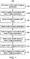
- the method 300 can begin at optional step 301, at which logging parameters of one or more modes of the router system 121 can be set.
- the router system can include a logging mode 1 that implements "level 1" logging described above and can further include a logging mode 2 that implements "level 2" logging described above.
- the respective logging parameters of each of the modes 1 and 2 can include respective logging rates, maximum numbers of writes and types of information logged.
- the logging parameters can be set or altered by a user during initialization of the router system 201, can be pre-stored in the storage medium 124 by the vendor or manufacturer of the system 201 and/or can be remotely set or altered by the vendor or manufacturer of the system 201 through the network 110 from the system 101.
- the controller 122 of the system 221 can perform logging in accordance with mode 1 logging parameters. For example, as noted above, during normal operation, the controller 122 can log a minimal amount of diagnostic information related to connectivity, as specified by the mode 1 logging parameters, which can be stored in the storage medium 124 and referenced by the controller 122. Specific information that can be logged in accordance with the first mode can include: most recent reboot time, DHCP information and/or PPPoE information.
- the controller 122 can also log the diagnostic information in accordance with a logging rate specified by the logging parameters of mode 1.
- the controller 122 in the first mode of operation, can be configured to log or write diagnostic information in the storage medium 124 once every N1 minutes.
- the controller 122 can also be limited by a maximum number of writes specified by the logging parameters of the first mode.
- the logging parameters can specify a maximum logging value M1, which can denote a maximum number of writes that the controller 122 can make for purposes of logging in the first mode since the most recent boot-up.
- the controller 122 can detect an operational problem with the router system 121. For example, as indicated above, the controller 122 can detect a freeze or an unexpected reboot, which can have been initiated by the user in response to the freeze. Alternatively, the reboot can be performed by the router due to a programming bug. In accordance with one exemplary implementation, an operational problem can be detected by determining and assessing the time between reboots. If this time is low, for example, every hour, this clearly indicates a problem and the mode 2 logging would be initiated. Similarly, if a WAN connection is not maintained for more than an hour at a time, this would also indicate a problem and would trigger mode 2 logging.
- the controller 122 can select mode 2 logging parameters in response to detecting the operational problem at step 304.
- the selection can be implemented by setting a mode 2 flag, as indicated above.
- the mode 2 logging parameters can specify a logging rate and/or a maximum number of writes in accordance with which the controller 122 institutes the logging of diagnostic information.
- the controller 122 can be configured to log or write diagnostic information in the storage medium 124 once every N2 minutes and/or can be limited by a maximum logging value M2, which can denote a maximum number of writes that the controller 122 can make for purposes of logging in the second mode since the most recent boot-up.
- the logging rate and the maximum number of writes of mode 2 can be greater than the logging rate and the maximum number of writes of mode 1, respectively.
- the controller 122 when operating under mode 2, can log diagnostic information that is composed of a greater amount of data than the diagnostic information logged according to mode 1.
- the mode 2 logging parameters can specify logging of diagnostic information that is in addition to and/or is different from diagnostic information logged according to mode 1.
- the diagnostic information of mode 2 can include any one or more of the following: firewall logs, LAN DHCP transactions, interface settings logs and IGMP logs.
- the logging parameters of mode 1 can exclude specifications for logging any one or more of these types of information. Accordingly, the controller 122 can log diagnostic information in mode 2 that is more comprehensive than diagnostic information logged in mode 1 to better enable the controller 122 to determine a repair for the detected operational problem.
- the controller 122 can log diagnostic information in accordance with the mode 2 logging parameters described above with respect to step 306. For example, the controller 122 can log diagnostic information in accordance with a logging rate and/or a maximum number of writes as specified by the logging parameters of mode 2. In addition, the controller 122 can log diagnostic information in accordance with mode 2 that is different from and/or more comprehensive than the diagnostic information logged in accordance with mode 1.
- the controller 122 can repair the router system 121 and address the operational problem identified at step 304 based on the diagnostic information logged in accordance with mode 1 and/or diagnostic information logged in accordance with mode 2.
- the controller 122 can employ standard debugging or troubleshooting tools to determine repair routines and apply the routines to the router system 121.
- the controller 122 can examine MoCA logs and determine if there were interfering systems on the coax connection which cause the MoCA to fail.
- the controller 122 can direct such systems to shut down or can notify the user that such systems should be shut down.
- a repair can include altering the logging parameters of mode 1 and/or mode 2 stored in the storage medium 124.
- the repair can include altering any one or more of the logging rates (e.g., N1 and/or N2), the maximum number of writes (M1 and/or M2) and the types of information logged for mode 1 and/or mode 2.
- the controller 122 can tailor the logging parameters to obtain information specifically directed to diagnosing and repairing particular operational problems detected in the past, including the operational problem detected or identified at step 304.
- the mode 2 logs could record many more parameters about how the MoCA system is operating.
- the mode 2 logs can include MoCA performance metrics, such as the current signal-to-noise and the maximum bit rate between nodes.
- MoCA performance metrics such as the current signal-to-noise and the maximum bit rate between nodes.
- any logging rates and maximum number of writes for mode 2 should be larger than logging rates and maximum number of writes for mode 1.
- the controller 122 can select mode 1 logging parameters stored in the storage medium 124 in response to completing the repair. For example, the controller 122 can revert to the logging parameters employed at step 302 or can select any logging parameters of mode 1 altered at step 310. As indicated above, the selection can be implemented by setting a flag for mode 1.
- the controller 122 can perform logging in accordance with mode 1 logging parameters selected at step 312.
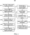
- an exemplary embodiment of an alternative logging method 400 in accordance with the present principles is illustratively depicted.
- the method 400 can be performed by the router system 121 and can be performed simultaneously with and can complement the method 500, described in more detail herein below.
- the method 400 can begin at optional step 401, at which logging parameters of one or more modes of the router system 121 can be set.
- the router system can include the logging mode 1 described above and can further include the logging mode 2 described above.
- the respective logging parameters of each of the modes 1 and 2 can include respective logging rates, maximum numbers of writes and types of information logged.
- the logging parameters can be set or altered by the controller 102 remotely during initialization of the router system 201, can be pre-stored in the storage medium 124 by the vendor or manufacturer of the system 201 and/or can be remotely set or altered by the vendor or manufacturer of the system 201 through the network 110 from the system 101.
- the controller 122 can perform logging in accordance with mode 1 logging parameters.
- the controller 122 can log diagnostic information in accordance with mode 1 logging parameters as described above with respect to step 302 of the method 300.
- the controller 122 can detect an operational problem with the router system 121.
- the controller 122 can detect an operational problem as described above with respect to step 304.
- the controller 122 can direct the communication interface 126 to transmit an indication or an identification of the detected operational problem to the technical support system 101 over the network 110.
- the controller 122 can remotely receive instructions, through the communication interface 126, to switch the logging mode from mode 1 to mode 2.
- the instructions can be received from the technical support system 101 via the network 110.
- the technical support system 101 can transmit the instructions to switch the logging mode should it deem the diagnostic information, which can be transmitted to the technical support system 101 by the controller 122, logged in accordance with mode 1 insufficient to solve the operational problem.
- One advantage of remotely controlling the mode setting through the technical support system 101 is that the vendor or manufacturer, which operates the technical support system 101, can limit the number of instances in which the router system 121 performs logging in accordance with mode 2.
- the technical support system 101 can prevent the router system 121 from performing an excessive amount of writes, thereby ensuring that the router system can reach a minimum service life.
- the technical support system can monitor the modes with which the router system 121 logs diagnostic information to periodically estimate the number of writes the router system 121 has made since the router system 121 was initialized.
- the technical support system 101 can compare the estimate to service life models and can minimize the application of mode 2 logging near the end of the determined service life of the router system 121.
- the controller 122 can log diagnostic information in accordance with the mode 2 logging parameters.
- the controller 122 can log diagnostic information in accordance with the mode 2 logging parameters as described above with respect to step 308.
- the controller 122 can direct the communication interface 126 to transmit the logs generated in accordance with mode 2 at step 410 to the technical support system 101 via the network 110.
- the controller 122 can receive repair instructions from the technical support system 101 through the communication interface 126 via the network 110.
- the repair instructions can include indications of or identifications of the repair routines described above with respect to step 310.
- the repair instructions can also include indications of or specifications of the alterations, described above with respect to step 310, of the logging parameters of mode 1 and/or mode 2 stored in the storage medium 124.
- the controller 122 can implement the repair instructions received at step 414 in the router system 121.
- the controller 122 can perform the repair routines described above with respect to step 310.
- the controller can perform any alterations of logging parameters indicated or specified in the instructions received at step 414.
- the method can iterate and loop steps 414 and 416, as multiple communications between the controller 122 and the technical support system 101 can be needed to implement the repair and address the problem identified at step 404.
- the controller 122 can implement the instructions and can transmit any results of the implementations to the technical support system 101.
- the technical support system 101 can generate and transmit new repair instructions to the router system 121 based on the results.
- the controller 122 can select mode 1 logging parameters in response to completing the repair. For example, similar to step 312 described above, the controller 122 can revert to the logging parameters employed at step 402 or can select any logging parameters of mode 1 altered at step 416. As indicated above, the selection can be implemented by setting a flag for mode 1. In addition, in alternative embodiments, the selection can be prompted by instructions received from the technical support system 101.
- the controller 122 can perform logging in accordance with mode 1 logging parameters selected at step 418.
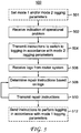
- an exemplary embodiment of an alternative logging method 500 in accordance with the present principles is illustratively depicted. It should be understood that the method 500 can be performed by the technical support system 101 and, as noted above, can be performed simultaneously with and can complement the method 400.
- the method 500 can begin at optional step 501, at the controller 102 can remotely set logging parameters of mode 1 and/or mode 2 of the router system 121 during initialization, as, for example, described above with respect to step 401.
- the controller 102 can receive an indication of or an identification of an operational problem from the router system 121 through the communication interface 106 via the network 110.
- the controller 102 can receive the indication of or the identification of the operational problem transmitted at step 406 of the method 400.
- the controller 102 can direct the communication interface 106 to remotely transmit instructions to switch the logging mode from mode 1 to mode 2 to the router system 121 via the network 110.
- the controller 102 can direct the transmission of the instructions received by the router system 121 in accordance with step 408 described above.
- the remote control of the mode setting can prevent the router system 121 from performing an excessive amount of writes and can ensure that the router system can reach a minimum service life.
- the controller 102 of the technical support system 101 can monitor the modes with which the router system 121 logs diagnostic information and can periodically estimate the number of writes the router system 121 has made since the router system 121 was initialized.
- the controller 102 can compare the estimate to service life models stored in the storage medium 104 and can minimize the use of mode 2 logging in the system 121 to extend the service life of the router system 121, as described above with respect to step 408.
- the controller 102 can receive logs generated in accordance with mode 2 from the router system 121 through the communication interface 106 via the network 110.
- the controller 102 can receive the logs transmitted by the router system 121 at step 412.
- the controller 102 can direct the repair module 108 to determine repair instructions to address the operational problem identified or indicated by step 502 based on the diagnostic information logged by the router system 121 in accordance with mode 1 and/or diagnostic information logged by the router system 121 in accordance with mode 2.
- the repair module 108 can employ standard debugging or troubleshooting tools to determine repair routines, as described above with respect to step 310 of the method 300.
- the controller 102 can add, to the repair instructions, instructions to alter the logging parameters of mode 1 and/or mode 2 stored in the storage medium 124.
- the alterations can be the same alterations described above with respect to step 310.
- the controller 102 can tailor the logging parameters to obtain information specifically directed to diagnosing and repairing particular operational problems detected in the past. Such problems can include the problem identified or indicated at step 502.
- the controller 102 can direct the communication interface 106 to remotely transmit the repair instructions to the router system 121.
- the method 500 can iterate and loop steps 508 and 510, as multiple communications between the controller 101 and the router system 121 can be needed to implement the repair and address the problem identified at step 502.
- the controller 102 can direct the communication interface 106 to remotely transmit, to the router system 121 via the network 110, instructions to perform logging in accordance with mode 1 in response to the completion of the repair.
- the router system 121 can be configured to perform step 418 automatically in response to completion of the repair, without direction from the controller 102.
- aspects of the present principles described herein provide several advantages and benefits.
- use of different logging modes that are tailored to specific operational characteristics of a computing device can be employed to reduce writing to generate logs and thereby extend the service life of the device.
- the remote setting of the logging modes by a vendor or a manufacturer of the device ensures that the use of enhanced logging modes can be limited and that the device meets minimum service life specifications.
Landscapes
- Engineering & Computer Science (AREA)
- Theoretical Computer Science (AREA)
- Signal Processing (AREA)
- General Engineering & Computer Science (AREA)
- Computer Networks & Wireless Communication (AREA)
- Quality & Reliability (AREA)
- General Physics & Mathematics (AREA)
- Physics & Mathematics (AREA)
- Computer Hardware Design (AREA)
- Computer Security & Cryptography (AREA)
- Computing Systems (AREA)
- Data Exchanges In Wide-Area Networks (AREA)
- Debugging And Monitoring (AREA)
Description
- The present invention generally relates to logging diagnostic information, and, more particularly, to logging systems, methods and devices for routers and similar computing devices.
- Routers have implemented a variety of logging methods to enable compiling and retention of diagnostic information.
US2007/067675A1 discloses managing data related to the failure of a device, comprising storing logging data and providing them to a human operator for analysis.US2002/198983A1 discloses a system providing a multiple level logging system having a first level for detecting message level errors and a second trace level for obtaining trace information to provide more details to be used for implementing corrective action. The frequency of logging can be adjusted upward in response to detection of an error and can then be decreased. For example, a physically separate non-volatile RAM (random access memory) that is separate from the main flash memory has been maintained in such routers for logging. The separate memory is used in this case to avoid wearing out the main non-volatile RAM. Other methods simply assume that the flash memory will not wear out in the lifetime of the product. However, an excessive amount of logging, as can be induced by a problem in the router, can render the lifetime estimate inaccurate and can prematurely cause failure of the memory of an electronic device. - One embodiment is directed to a method. In accordance with the method first diagnostic information is logged in a router in accordance with a first mode having a first logging rate. In addition, an operational problem within the router is detected. Further, in response to detecting the operational problem, second diagnostic information is logged in accordance with a second mode having a second logging rate that is greater than the first logging rate of the first mode.
- An alternative embodiment is directed to an operational router apparatus that includes a communication interface and a controller. The controller configured to log first diagnostic information in a router in accordance with a first mode and to detect an operational problem within the router. In addition, the communication interface is configured to transmit an indication of the operational problem and to remotely receive instructions to log second diagnostic information in the router in accordance with a second mode. The controller is further configured to log the second diagnostic information in accordance with the second mode in response to receipt of the instructions. Here, the second diagnostic information is composed of a larger amount of data than the first diagnostic information.
- Another embodiment is directed to a system that includes a communication interface and a controller. The communication interface is configured to remotely receive an indication of an operational problem at a router. Further, the controller is configured to direct the communication interface to transmit instructions to the router that direct the router to switch a logging mode from a first mode to a second mode. First diagnostic information is logged at the router in accordance with the first mode and second diagnostic information is logged at the router in accordance with the second mode. The second diagnostic information is composed of a larger amount of data than the first diagnostic
- Embodiments relate only to claimed combinations of features. In the following, when the term "embodiment" relates to unclaimed combinations of features, said term has to be understood as referring to examples of the present invention.
- The teachings of the present invention can be readily understood by considering the following detailed description in conjunction with the accompanying drawings, in which:
-
FIG. 1 is a high-level block/flow diagram of an exemplary embodiment of a logging system in accordance with the present principles; -
FIG. 2 is a high-level block/flow diagram of an exemplary embodiment of a broadband home router in accordance with the present principles; -
FIG. 3 is a high-level flow diagram of an exemplary embodiment of a logging method in accordance with the present principles; -
FIG. 4 is a high-level flow diagram of an exemplary embodiment of an alternative logging method in accordance with the present principles; and -
FIG. 5 is a high-level flow diagram of another exemplary embodiment of an alternative logging method in accordance with the present principles. - It should be understood that the drawings are for purposes of illustrating the concepts of the present principles and are not necessarily the only possible configuration for illustrating the present principles. To facilitate understanding, identical reference numerals have been used, where possible, to designate identical elements that are common to the figures.
- The present principles are directed to methods, systems and apparatuses for logging diagnostic information. In accordance with exemplary aspects of the present principles, multiple logging modes can be employed to log diagnostic information in a way that minimally affects the service life of the memory used to store the logs and that maintains effectiveness of the logs in enabling repairs of the system. In particular, the logging can be switched to a more comprehensive mode in response to detecting certain problems in the system, such as freezing and unexpected rebooting. According to one feature, the logging mode can be altered so that more relevant or different information is logged. Alternatively or additionally, the logging mode can be altered such that the logging rate is increased and/or the maximum number of writes is changed in response to detecting a problem. Advantageously, the logging mode alteration can be directed remotely at a vendor technical support site in response to receiving an indication that a problem has been detected by the system or by a user of the system. This feature enables the vendor to retain proprietary control of system settings and thereby ensure that the life of the system is not prematurely shortened by the user. For example, the remote settings of the logging modes can be monitored and can be compared to system models to ensure that the system has at least a minimum service life in accordance with system specifications provided by the vendor to users.
- It should be understood that those skilled in the art will be able to devise various arrangements that, although not explicitly described or shown herein, embody the present principles and are included within its scope.
- All examples and conditional language recited herein are intended for pedagogical purposes to aid the reader in understanding the present principles and the concepts contributed by the inventor(s) to furthering the art, and are to be construed as being without limitation to such specifically recited examples and conditions.
- Moreover, all statements herein reciting principles, aspects, and embodiments of the present principles, as well as specific examples thereof, are intended to encompass both structural and functional equivalents thereof. Additionally, it is intended that such equivalents include both currently known equivalents as well as equivalents developed in the future, i.e., any elements developed that perform the same function, regardless of structure.
- Thus, for example, it will be appreciated by those skilled in the art that the block diagrams presented herein represent conceptual views of illustrative circuitry embodying the present principles. Similarly, it will be appreciated that any flow charts, flow diagrams, state transition diagrams, pseudocode, and the like represent various processes which can be substantially represented in computer readable media and so executed by a computer or processor, whether or not such computer or processor is explicitly shown.
- The functions of the various elements shown in the figures can be provided through the use of dedicated hardware as well as hardware capable of executing software in association with appropriate software. When provided by a processor, the functions can be provided by a single dedicated processor, by a single shared processor, or by a plurality of individual processors, some of which can be shared. Moreover, explicit use of the term "processor" or "controller" should not be construed to refer exclusively to hardware capable of executing software, and can implicitly include, without limitation, digital signal processor ("DSP") hardware and also computer readable storage mediums for storing software, such as read-only memory ("ROM"), random access memory ("RAM"), and non-volatile storage.
- Other hardware, conventional and/or custom, can also be included. Similarly, any switches shown in the figures are conceptual only. Their function can be carried out through the operation of program logic, through dedicated logic, through the interaction of program control and dedicated logic, or even manually, the particular technique being selectable by the implementer as more specifically understood from the context.
- In the claims hereof, any element expressed as a means for performing a specified function is intended to encompass any way of performing that function including, for example, a) a combination of circuit elements that performs that function or b) software in any form, including, therefore, firmware, microcode or the like, combined with appropriate circuitry for executing that software to perform the function. The present principles as defined by such claims reside in the fact that the functionalities provided by the various recited means are combined and brought together in the manner which the claims call for. It is thus regarded that any means that can provide those functionalities are equivalent to those shown herein.
- Reference in the specification to "one embodiment" or "an embodiment" of the present principles, as well as other variations thereof, means that a particular feature, structure, characteristic, and so forth described in connection with the embodiment is included in at least one embodiment of the present principles. Thus, the appearances of the phrase "in one embodiment" or "in an embodiment", as well any other variations, appearing in various places throughout the specification are not necessarily all referring to the same embodiment.
- It is to be appreciated that the use of any of the following "/", "and/or", and "at least one of', for example, in the cases of "A/B", "A and/or B" and "at least one of A and B", is intended to encompass the selection of the first listed option (A) only, or the selection of the second listed option (B) only, or the selection of both options (A and B). As a further example, in the cases of "A, B, and/or C" and "at least one of A, B, and C", such phrasing is intended to encompass the selection of the first listed option (A) only, or the selection of the second listed option (B) only, or the selection of the third listed option (C) only, or the selection of the first and the second listed options (A and B) only, or the selection of the first and third listed options (A and C) only, or the selection of the second and third listed options (B and C) only, or the selection of all three options (A and B and C). This can be extended, as readily apparent by one of ordinary skill in this and related arts, for as many items listed.
- As indicated above, the logging of events is very important for certain equipment, such as a broadband home router (BHR) and the like, because the logging records the past and present state of the device and aids in troubleshooting any problems that a consumer might have with the device. Logging is utilized to record events to enable the determination of sources of failure as well as proper operation and to identify hacking threats. If the information is logged in only volatile memory and the device reboots because of an operational problem, then the logging information can be lost at a time when it is most crucial to record. As a result, the main flash memory has been used to store such information.
- Logging, while straightforward for a standard computer, is difficult in the context of a contemporary consumer electronics design, such as in a BHR. The main difficulty is the estimation of the projected number of writes to the flash memory, which is finite and is currently thought to be no more than 100,000, possibly as low as 10,000. In the past, this condition was usually solved by adding additional Electrically Erasable Programmable Read-Only Memory (EEPROM) technology, where 10,000,000 writes capability is the norm. However, due to cost constraints, only non-volatile memory of the flash itself is used for logging purposes. An analysis was performed on the number of writes used for a typical logging system, and it was found that it is possible to encounter some cases where the flash fails before the electronic device itself becomes obsolete. Consequently, writing all of the logging information to non-volatile RAM can prematurely end the life of the product. As such, rather than fulfilling a full logging functionality completely, a conditional non-volatile logging system/method can be used.
- As stated above, the purpose of a logging system is to enable the performance of a forensic analysis of a problem and to enable the use of this information to correct it. Of course, as indicated above, if a problem causes a reboot and the logs are stored in volatile memory, then the logs can be lost. On the other hand, the number of times in normal operation that a freeze/reboot occurs can be a relatively small number, and much of the logging (and attendant writing to the flash memory) would be wasted. Thus, by implementing a scheme whereby logs can be written to non-volatile RAM only if the situation warrants it - e.g., an issue which causes a reboot - the device can maintain the ability to assist in diagnosing issues, while still maintaining a long life.
- As described herein below, a new logging scheme, which is referred to herein as "persistent logging," can be utilized based on a set of conditions that exist in an electronic device, such as a BHR, itself. In accordance with an aspect of the present principles, logging information is stored in an electronic device's non-volatile memory only for repair/debugging purposes, thereby greatly reducing the number of writes to the memory. The logging system is particularly efficient when electronic memory is used.
- In accordance with one exemplary aspect, under normal conditions, the electronic device (e.g., BHR) records a minimal amount of information, and limits itself to no more than one write every N1 minutes. The actual times can be decided based on operational factors. This is designated as a "
Level 1" condition; the minimum information in this case corresponds to relevant information gathered since the most recent reboot time. Such information can be related to connectivity issues in accordance with DHCP (dynamic host control protocol) or PPPoE (Point to Point Protocol over Ethernet), and is not be gathered very often. - In turn, a "
Level 2" condition permits writes every N2 minutes, where N2 is less than N1, and can prompt the device to generate one or more of the following logs: firewall logs, LAN (local area network) DHCP transactions, interface settings logs, IGMP (Internet Gateway Management Protocol) logs, as well as other logs as appropriate or specified by an administrator. - Operational factors that can be considered to set "N1" and "N2" can include the number of writes available to the memory, the estimated number of writes per second and the operational life of the product. For the "N1" range, it is estimated that once per hour would be sufficient, while "N2" can be as high as once per second. However, the values can be varied based on the operational factors.
-
Level 1 andLevel 2 Flags, as well as N1 and N2, in the device can be remotely settable, using, for example, TR-069 (CPE (Customer Premises Equipment) WAN (Wide Area Network) Management Protocol) vendor extensions. This feature enables a technical support representative to increase the persistent logging amount in the event a customer is having difficulty with the device as a result of freezing/rebooting. In addition, maximum logging values, M1 and M2, can be set so that persistent logging does not overwhelm the flash space in the event that a debugging/repair process was inadvertently left running. For example, M1 can be set to 1 kilobyte per hour, while M2 can be set to a rate as high as 1 megabyte per hour. - In accordance with another exemplary aspect, logs stored in main memory can be consulted primarily in the event that a router has a problem, where freezing/rebooting is not an issue.
- Referring now in specific detail to the drawings in which like reference numerals identify similar or identical elements throughout the several views, and initially to
FIG. 1 , a system/apparatus 100 of an embodiment of the present principles is illustratively depicted. It should be understood that the aspects of the present principles described above can be implemented in the system, apparatus and method embodiments described herein. Thesystem 100 can include atechnical support system 101 and arouter system 121 that communicate through awide area network 110, such as the internet, which can be wired or wireless or can include both wired and wireless components. It should be noted that although features of the present principles are described herein with respect to arouter system 121, in accordance with alternative embodiments, thesystem 121 can be any other appropriate computing system. Therouter system 121 can include acontroller 122, acommunication interface 126, anetwork interface 128 and astorage medium 124. In turn, thetechnical support system 101 can include acontroller 102, acommunication interface 106, arepair module 108 and astorage medium 104. The functions of the various elements of thesystem 100 are described in more detail herein below with respect to specific apparatus and method embodiments. - Referring to
FIG. 2 with continuing reference toFIG. 1 , a morespecific implementation 200 of therouter system 121 is illustratively depicted. Thesystem 200 is a broadband home router and can include acontroller element 202, which can comprise a central processing unit (CPU), an Ethernet switch, a network processing unit (NPU) and a storage medium. Here, thecontroller element 202 is one exemplary implementation of thecontroller 122 and thestorage medium 124. Thesystem 200 can further include acommunication interface 204 and anetwork interface 206, which are exemplary implementations of thecommunication interface 126 and thenetwork interface 128, respectively. Thecommunication interface 204 can include acoaxial port 208 through which a connection to thenetwork 110 can be made. In addition, thecommunication interface 204 can include a multiplexer/demultiplexer 210 for both LAN frequencies and WAN frequencies and MoCA (Multimedia over Coax Alliance) switches 212 and 214 for LAN traffic (about 1125 MHz to about 1525 MHz (single channel)) and WAN traffic (about 975 MHz to about 1025 MHz, eight channels), respectively. Further, thenetwork interface 206 can be employed to connect to a user's home network and can include a Wi-Fi interface 216, asystem bus 218, RJ-45LAN interfaces 220 and an RJ-45WAN interface 222. - With reference to
FIG. 3 , with continuing reference toFIG. 1 , an exemplary embodiment of a logging method in accordance with the present principles is illustratively depicted. Themethod 300 can begin atoptional step 301, at which logging parameters of one or more modes of therouter system 121 can be set. For example, the router system can include alogging mode 1 that implements "level 1" logging described above and can further include alogging mode 2 that implements "level 2" logging described above. The respective logging parameters of each of themodes storage medium 124 by the vendor or manufacturer of the system 201 and/or can be remotely set or altered by the vendor or manufacturer of the system 201 through thenetwork 110 from thesystem 101. - At
step 302, thecontroller 122 of the system 221 can perform logging in accordance withmode 1 logging parameters. For example, as noted above, during normal operation, thecontroller 122 can log a minimal amount of diagnostic information related to connectivity, as specified by themode 1 logging parameters, which can be stored in thestorage medium 124 and referenced by thecontroller 122. Specific information that can be logged in accordance with the first mode can include: most recent reboot time, DHCP information and/or PPPoE information. - In addition, the
controller 122 can also log the diagnostic information in accordance with a logging rate specified by the logging parameters ofmode 1. For example, as indicated above, in the first mode of operation, thecontroller 122 can be configured to log or write diagnostic information in thestorage medium 124 once every N1 minutes. Further, thecontroller 122 can also be limited by a maximum number of writes specified by the logging parameters of the first mode. For example, as indicated above, the logging parameters can specify a maximum logging value M1, which can denote a maximum number of writes that thecontroller 122 can make for purposes of logging in the first mode since the most recent boot-up. - At
step 304, thecontroller 122 can detect an operational problem with therouter system 121. For example, as indicated above, thecontroller 122 can detect a freeze or an unexpected reboot, which can have been initiated by the user in response to the freeze. Alternatively, the reboot can be performed by the router due to a programming bug. In accordance with one exemplary implementation, an operational problem can be detected by determining and assessing the time between reboots. If this time is low, for example, every hour, this clearly indicates a problem and themode 2 logging would be initiated. Similarly, if a WAN connection is not maintained for more than an hour at a time, this would also indicate a problem and would triggermode 2 logging. - At
step 306, thecontroller 122 can selectmode 2 logging parameters in response to detecting the operational problem atstep 304. The selection can be implemented by setting amode 2 flag, as indicated above. Similar to themode 1 logging parameters, themode 2 logging parameters can specify a logging rate and/or a maximum number of writes in accordance with which thecontroller 122 institutes the logging of diagnostic information. For example, as indicated above, thecontroller 122 can be configured to log or write diagnostic information in thestorage medium 124 once every N2 minutes and/or can be limited by a maximum logging value M2, which can denote a maximum number of writes that thecontroller 122 can make for purposes of logging in the second mode since the most recent boot-up. Further, the logging rate and the maximum number of writes ofmode 2 can be greater than the logging rate and the maximum number of writes ofmode 1, respectively. As such, thecontroller 122, when operating undermode 2, can log diagnostic information that is composed of a greater amount of data than the diagnostic information logged according tomode 1. In addition, themode 2 logging parameters can specify logging of diagnostic information that is in addition to and/or is different from diagnostic information logged according tomode 1. For example, as indicated above, the diagnostic information ofmode 2 can include any one or more of the following: firewall logs, LAN DHCP transactions, interface settings logs and IGMP logs. Furthermore, the logging parameters ofmode 1 can exclude specifications for logging any one or more of these types of information. Accordingly, thecontroller 122 can log diagnostic information inmode 2 that is more comprehensive than diagnostic information logged inmode 1 to better enable thecontroller 122 to determine a repair for the detected operational problem. - At
step 308, thecontroller 122 can log diagnostic information in accordance with themode 2 logging parameters described above with respect to step 306. For example, thecontroller 122 can log diagnostic information in accordance with a logging rate and/or a maximum number of writes as specified by the logging parameters ofmode 2. In addition, thecontroller 122 can log diagnostic information in accordance withmode 2 that is different from and/or more comprehensive than the diagnostic information logged in accordance withmode 1. - At
step 310, thecontroller 122 can repair therouter system 121 and address the operational problem identified atstep 304 based on the diagnostic information logged in accordance withmode 1 and/or diagnostic information logged in accordance withmode 2. For example, thecontroller 122 can employ standard debugging or troubleshooting tools to determine repair routines and apply the routines to therouter system 121. In one exemplary implementation, thecontroller 122 can examine MoCA logs and determine if there were interfering systems on the coax connection which cause the MoCA to fail. Here, thecontroller 122 can direct such systems to shut down or can notify the user that such systems should be shut down. In another example, thecontroller 122 can determine that an Ethernet cable was incorrectly installed into the WAN port by examining the DCHP logs and can inform the user of the incorrect installation. In accordance with other exemplary aspects, a repair can include altering the logging parameters ofmode 1 and/ormode 2 stored in thestorage medium 124. For example, the repair can include altering any one or more of the logging rates (e.g., N1 and/or N2), the maximum number of writes (M1 and/or M2) and the types of information logged formode 1 and/ormode 2. In addition, thecontroller 122 can tailor the logging parameters to obtain information specifically directed to diagnosing and repairing particular operational problems detected in the past, including the operational problem detected or identified atstep 304. For example, suppose that the MoCA system is not working properly according to themode 1 logs. Themode 2 logs could record many more parameters about how the MoCA system is operating. For example, themode 2 logs can include MoCA performance metrics, such as the current signal-to-noise and the maximum bit rate between nodes. However, it should be noted that any logging rates and maximum number of writes formode 2 should be larger than logging rates and maximum number of writes formode 1. - At
step 312, thecontroller 122 can selectmode 1 logging parameters stored in thestorage medium 124 in response to completing the repair. For example, thecontroller 122 can revert to the logging parameters employed atstep 302 or can select any logging parameters ofmode 1 altered atstep 310. As indicated above, the selection can be implemented by setting a flag formode 1. - At
step 314, thecontroller 122 can perform logging in accordance withmode 1 logging parameters selected atstep 312. - With reference now to
FIG. 4 , with continuing reference toFIGS. 1 and3 , an exemplary embodiment of analternative logging method 400 in accordance with the present principles is illustratively depicted. It should be understood that themethod 400 can be performed by therouter system 121 and can be performed simultaneously with and can complement themethod 500, described in more detail herein below. Themethod 400 can begin at optional step 401, at which logging parameters of one or more modes of therouter system 121 can be set. For example, the router system can include thelogging mode 1 described above and can further include thelogging mode 2 described above. For example, the respective logging parameters of each of themodes controller 102 remotely during initialization of the router system 201, can be pre-stored in thestorage medium 124 by the vendor or manufacturer of the system 201 and/or can be remotely set or altered by the vendor or manufacturer of the system 201 through thenetwork 110 from thesystem 101. - At
step 402, thecontroller 122 can perform logging in accordance withmode 1 logging parameters. For example, thecontroller 122 can log diagnostic information in accordance withmode 1 logging parameters as described above with respect to step 302 of themethod 300. - At
step 404, thecontroller 122 can detect an operational problem with therouter system 121. For example, thecontroller 122 can detect an operational problem as described above with respect to step 304. - At
step 406, thecontroller 122 can direct thecommunication interface 126 to transmit an indication or an identification of the detected operational problem to thetechnical support system 101 over thenetwork 110. - At
step 408, thecontroller 122 can remotely receive instructions, through thecommunication interface 126, to switch the logging mode frommode 1 tomode 2. The instructions can be received from thetechnical support system 101 via thenetwork 110. Here, thetechnical support system 101 can transmit the instructions to switch the logging mode should it deem the diagnostic information, which can be transmitted to thetechnical support system 101 by thecontroller 122, logged in accordance withmode 1 insufficient to solve the operational problem. One advantage of remotely controlling the mode setting through thetechnical support system 101 is that the vendor or manufacturer, which operates thetechnical support system 101, can limit the number of instances in which therouter system 121 performs logging in accordance withmode 2. As such, thetechnical support system 101 can prevent therouter system 121 from performing an excessive amount of writes, thereby ensuring that the router system can reach a minimum service life. The technical support system can monitor the modes with which therouter system 121 logs diagnostic information to periodically estimate the number of writes therouter system 121 has made since therouter system 121 was initialized. Thetechnical support system 101 can compare the estimate to service life models and can minimize the application ofmode 2 logging near the end of the determined service life of therouter system 121. - At step 410, the
controller 122 can log diagnostic information in accordance with themode 2 logging parameters. For example, thecontroller 122 can log diagnostic information in accordance with themode 2 logging parameters as described above with respect to step 308. - At
step 412, thecontroller 122 can direct thecommunication interface 126 to transmit the logs generated in accordance withmode 2 at step 410 to thetechnical support system 101 via thenetwork 110. - At
step 414, thecontroller 122 can receive repair instructions from thetechnical support system 101 through thecommunication interface 126 via thenetwork 110. The repair instructions can include indications of or identifications of the repair routines described above with respect to step 310. The repair instructions can also include indications of or specifications of the alterations, described above with respect to step 310, of the logging parameters ofmode 1 and/ormode 2 stored in thestorage medium 124. - At
step 416, thecontroller 122 can implement the repair instructions received atstep 414 in therouter system 121. For example, thecontroller 122 can perform the repair routines described above with respect to step 310. In addition, the controller can perform any alterations of logging parameters indicated or specified in the instructions received atstep 414. It should be noted that the method can iterate andloop steps controller 122 and thetechnical support system 101 can be needed to implement the repair and address the problem identified atstep 404. For example, thecontroller 122 can implement the instructions and can transmit any results of the implementations to thetechnical support system 101. In addition, thetechnical support system 101 can generate and transmit new repair instructions to therouter system 121 based on the results. - At
step 418, thecontroller 122 can selectmode 1 logging parameters in response to completing the repair. For example, similar to step 312 described above, thecontroller 122 can revert to the logging parameters employed atstep 402 or can select any logging parameters ofmode 1 altered atstep 416. As indicated above, the selection can be implemented by setting a flag formode 1. In addition, in alternative embodiments, the selection can be prompted by instructions received from thetechnical support system 101. - At step 420, the
controller 122 can perform logging in accordance withmode 1 logging parameters selected atstep 418. - With reference now to
FIG. 5 , with continuing reference toFIGS. 1 ,3 and4 , an exemplary embodiment of analternative logging method 500 in accordance with the present principles is illustratively depicted. It should be understood that themethod 500 can be performed by thetechnical support system 101 and, as noted above, can be performed simultaneously with and can complement themethod 400. - The
method 500 can begin atoptional step 501, at thecontroller 102 can remotely set logging parameters ofmode 1 and/ormode 2 of therouter system 121 during initialization, as, for example, described above with respect to step 401. - At
step 502, thecontroller 102 can receive an indication of or an identification of an operational problem from therouter system 121 through thecommunication interface 106 via thenetwork 110. For example, thecontroller 102 can receive the indication of or the identification of the operational problem transmitted atstep 406 of themethod 400. - At
step 504, thecontroller 102 can direct thecommunication interface 106 to remotely transmit instructions to switch the logging mode frommode 1 tomode 2 to therouter system 121 via thenetwork 110. For example, thecontroller 102 can direct the transmission of the instructions received by therouter system 121 in accordance withstep 408 described above. As described above with respect to step 408, the remote control of the mode setting can prevent therouter system 121 from performing an excessive amount of writes and can ensure that the router system can reach a minimum service life. Further, thecontroller 102 of thetechnical support system 101 can monitor the modes with which therouter system 121 logs diagnostic information and can periodically estimate the number of writes therouter system 121 has made since therouter system 121 was initialized. Moreover, thecontroller 102 can compare the estimate to service life models stored in thestorage medium 104 and can minimize the use ofmode 2 logging in thesystem 121 to extend the service life of therouter system 121, as described above with respect to step 408. - At
step 506, thecontroller 102 can receive logs generated in accordance withmode 2 from therouter system 121 through thecommunication interface 106 via thenetwork 110. For example, thecontroller 102 can receive the logs transmitted by therouter system 121 atstep 412. - At
step 508, thecontroller 102 can direct therepair module 108 to determine repair instructions to address the operational problem identified or indicated bystep 502 based on the diagnostic information logged by therouter system 121 in accordance withmode 1 and/or diagnostic information logged by therouter system 121 in accordance withmode 2. For example, therepair module 108 can employ standard debugging or troubleshooting tools to determine repair routines, as described above with respect to step 310 of themethod 300. In accordance with other exemplary aspects, thecontroller 102 can add, to the repair instructions, instructions to alter the logging parameters ofmode 1 and/ormode 2 stored in thestorage medium 124. For example, the alterations can be the same alterations described above with respect to step 310. As indicated above with respect to the customization of logging parameters atstep 310, thecontroller 102 can tailor the logging parameters to obtain information specifically directed to diagnosing and repairing particular operational problems detected in the past. Such problems can include the problem identified or indicated atstep 502. - At
step 510, thecontroller 102 can direct thecommunication interface 106 to remotely transmit the repair instructions to therouter system 121. As described above with respect tosteps method 500 can iterate andloop steps controller 101 and therouter system 121 can be needed to implement the repair and address the problem identified atstep 502. - At
optional step 512, thecontroller 102 can direct thecommunication interface 106 to remotely transmit, to therouter system 121 via thenetwork 110, instructions to perform logging in accordance withmode 1 in response to the completion of the repair. Alternatively, therouter system 121 can be configured to performstep 418 automatically in response to completion of the repair, without direction from thecontroller 102. - As described above, aspects of the present principles described herein provide several advantages and benefits. In particular, use of different logging modes that are tailored to specific operational characteristics of a computing device can be employed to reduce writing to generate logs and thereby extend the service life of the device. Moreover, the remote setting of the logging modes by a vendor or a manufacturer of the device ensures that the use of enhanced logging modes can be limited and that the device meets minimum service life specifications.
- Having described preferred embodiments for systems, methods and apparatuses for logging diagnostic information (which are intended to be illustrative and not limiting), it is noted that modifications and variations can be made by persons skilled in the art in light of the above teachings. It is therefore to be understood that changes can be made in the particular embodiments of the invention disclosed which are within the scope of the invention as outlined by the appended claims. While the forgoing is directed to various embodiments of the present invention, other and further embodiments of the invention can be devised without departing from the basic scope thereof.
Claims (12)
- A method comprising:logging (402) first diagnostic information in a router in accordance with a first mode having a set of stored logging parameters including a first logging rate;detecting (404) an operational problem within the router;transmitting (406) an identification of the detected operational problem to a support apparatus; andin response to receiving (408) instructions to switch to a second mode from said support apparatus, logging (410) second diagnostic information in accordance with the second mode, wherein at least one logging parameter is altered in response to the received instructions, said alteration comprising increasing the logging rate from first logging rate to a second logging rate, greater than the first logging rate,wherein said first and second diagnostic information are stored in a memory of said router having a maximum number of writes and determining when to switch to the second mode is performed by said support apparatus according to a comparison between an estimate of the number of memory writes performed by the router and service life models.
- The method of claim 1, wherein said second diagnostic information is different from said first diagnostic information.
- The method of claim 1, wherein said second diagnostic information includes at least one of firewall logs, local area network (LAN) dynamic host configuration protocol (DHCP) transactions, interface settings logs or Internet Gateway Management Protocol (IGMP) logs.
- The method of claim 3, wherein said first diagnostic information excludes at least one of firewall logs, LAN DHCP transactions, Interface settings logs or IGMP logs.
- The method of claim 1, further comprising:transmitting (412) the second diagnostic information to the support apparatus;receiving (414) from said support apparatus repair instructions identifying repair routines;execute (416) the received repair instructions to repair the operational problem.
- The method of claim 5 wherein the logging (410) and repairing steps (414, 416) are iterated multiple times to repair the operational problem.
- An operational router apparatus (121) comprising:a controller (122) configured to:log first diagnostic information in the operational router apparatus in accordance with a first mode having a set of stored logging parameters;detect an operational problem within the operational router apparatus;a memory (124) configured to store at least diagnostic information, said memory having a maximum number of writes; anda communication interface (126) configured to:transmit an identification of the detected operational problem to a support apparatus;receive instructions to switch to a second mode from said support apparatus, configuring the controller to log second diagnostic information in accordance with the second mode, wherein at least one logging parameter is altered in response to the received instructions, said alteration comprising increasing the logging rate from first logging rate to a second logging rate, greater than the first logging rate, wherein determining when to switch to the second mode is performed by said support apparatus according to a comparison between an estimate of the number of memory writes performed by the operational router apparatus and service life models.
- The apparatus of claim 7, wherein the communication interface is further configured to transmit (412) the second diagnostic information to the support apparatus and to receive (414) repair instructions identifying repair routines, and the controller is further configured to execute (416) the received repair instructions to repair the operational problem.
- The apparatus of claim 7, wherein said first mode includes a first maximum number of writes that limits logging of said first diagnostic information by said controller, wherein said second mode includes a second maximum number of writes that limits logging said second diagnostic information by said controller and wherein said controller is further configured to alter at least one of said first maximum number of writes or said second maximum number of writes based on said repair instructions.
- The apparatus of claim 7, wherein said second diagnostic information is different from said first diagnostic information and wherein said operational problem is at least one of a freeze of said router or a reboot performed in response to said freeze.
- A support apparatus (101) comprising:a communication interface (106) configured to receive from an operational router apparatus according to any of claims 7 to 10 an identification of a detected operational problem and diagnostic logging information;a storage medium (104) storing service life models;a controller (102) configured to, upon reception of an identification of a detected operational problem, transmit instructions to the operational router apparatus to switch to a second logging mode having a set of parameters comprising an increased logging rate, wherein determining when to switch to the second mode is performed according to a comparison between an estimate of the number of memory writes performed by the operational router apparatus and the service life models.
- The support apparatus of claim 11 further comprising a repair module configured to determine repair instructions according to the received identification of a detected operational problem and diagnostic logging information, and wherein the communication interface (106) is further configured to transmit the repair instructions.
Applications Claiming Priority (2)
| Application Number | Priority Date | Filing Date | Title |
|---|---|---|---|
| US201161437924P | 2011-01-31 | 2011-01-31 | |
| PCT/US2012/020577 WO2012106066A1 (en) | 2011-01-31 | 2012-01-09 | Diagnostic information logging |
Publications (2)
| Publication Number | Publication Date |
|---|---|
| EP2671156A1 EP2671156A1 (en) | 2013-12-11 |
| EP2671156B1 true EP2671156B1 (en) | 2019-05-01 |
Family
ID=45563521
Family Applications (1)
| Application Number | Title | Priority Date | Filing Date |
|---|---|---|---|
| EP12702638.3A Active EP2671156B1 (en) | 2011-01-31 | 2012-01-09 | Diagnostic information logging |
Country Status (7)
| Country | Link |
|---|---|
| US (1) | US10425277B2 (en) |
| EP (1) | EP2671156B1 (en) |
| JP (1) | JP5969509B2 (en) |
| KR (1) | KR20140012084A (en) |
| CN (1) | CN103339608A (en) |
| BR (1) | BR112013019216A2 (en) |
| WO (1) | WO2012106066A1 (en) |
Families Citing this family (6)
| Publication number | Priority date | Publication date | Assignee | Title |
|---|---|---|---|---|
| US9361204B2 (en) * | 2013-02-19 | 2016-06-07 | Arm Limited | Generating trace data including a lockup identifier indicating occurrence of a lockup state |
| CN104427518A (en) * | 2013-08-19 | 2015-03-18 | 中兴通讯股份有限公司 | Router and method |
| US10255127B2 (en) | 2015-09-30 | 2019-04-09 | International Business Machines Corporation | Optimized diagnostic data collection driven by a ticketing system |
| JP6958311B2 (en) * | 2017-12-12 | 2021-11-02 | 富士通株式会社 | Information processing equipment, information processing systems and programs |
| US11379291B2 (en) * | 2020-04-07 | 2022-07-05 | Hewlett Packard Enterprise Development Lp | Application logging mechanism |
| US11494250B1 (en) * | 2021-06-14 | 2022-11-08 | EMC IP Holding Company LLC | Method and system for variable level of logging based on (long term steady state) system error equilibrium |
Family Cites Families (20)
| Publication number | Priority date | Publication date | Assignee | Title |
|---|---|---|---|---|
| ATE194238T1 (en) * | 1990-09-17 | 2000-07-15 | Cabletron Systems Inc | SYSTEM AND METHOD FOR MODELING A COMPUTER NETWORK |
| JPH06124012A (en) * | 1992-10-12 | 1994-05-06 | Mita Ind Co Ltd | Image forming device provided with self-repairing function |
| US6205239B1 (en) * | 1996-05-31 | 2001-03-20 | Texas Instruments Incorporated | System and method for circuit repair |
| US6202090B1 (en) * | 1997-12-11 | 2001-03-13 | Cisco Technology, Inc. | Apparatus and method for downloading core file in a network device |
| US6879995B1 (en) * | 1999-08-13 | 2005-04-12 | Sun Microsystems, Inc. | Application server message logging |
| US6691250B1 (en) * | 2000-06-29 | 2004-02-10 | Cisco Technology, Inc. | Fault handling process for enabling recovery, diagnosis, and self-testing of computer systems |
| US7120685B2 (en) * | 2001-06-26 | 2006-10-10 | International Business Machines Corporation | Method and apparatus for dynamic configurable logging of activities in a distributed computing system |
| US7260628B2 (en) * | 2002-09-06 | 2007-08-21 | Hitachi, Ltd. | Event notification in storage networks |
| US7263632B2 (en) * | 2003-05-07 | 2007-08-28 | Microsoft Corporation | Programmatic computer problem diagnosis and resolution and automated reporting and updating of the same |
| EP1745381A2 (en) | 2004-03-17 | 2007-01-24 | Riverstone Networks, Inc. | Managing process state information in an operating system environment |
| US8259593B2 (en) * | 2005-06-29 | 2012-09-04 | Honeywell International Inc. | Apparatus and method for segmenting a communication network |
| US7493525B2 (en) * | 2005-09-21 | 2009-02-17 | Cisco Technology, Inc. | Method and system for managing failure information |
| CN100555240C (en) * | 2007-01-16 | 2009-10-28 | 国际商业机器公司 | The method and system that is used for diagnosis of application program |
| US20090210283A1 (en) * | 2007-09-28 | 2009-08-20 | Fujitsu Limited | Support management method, support management system and information processing device |
| JP2010141655A (en) * | 2008-12-12 | 2010-06-24 | Yokogawa Electric Corp | Network monitoring device |
| US8924266B2 (en) * | 2009-04-30 | 2014-12-30 | Bank Of America Corporation | Self-service device inventory information control |
| EP2510439B1 (en) * | 2009-12-08 | 2022-05-04 | Hewlett Packard Enterprise Development LP | Managing errors in a data processing system |
| US9130766B2 (en) * | 2009-12-17 | 2015-09-08 | Verizon Patent And Licensing Inc. | System for and method of performing residential gateway diagnostics and corrective actions |
| US10447767B2 (en) * | 2010-04-26 | 2019-10-15 | Pure Storage, Inc. | Resolving a performance issue within a dispersed storage network |
| CA2817576C (en) * | 2010-11-24 | 2016-06-07 | Logrhythm, Inc. | Scalable analytical processing of structured data |
-
2012
- 2012-01-09 JP JP2013552529A patent/JP5969509B2/en not_active Expired - Fee Related
- 2012-01-09 KR KR1020137023124A patent/KR20140012084A/en active Search and Examination
- 2012-01-09 WO PCT/US2012/020577 patent/WO2012106066A1/en active Application Filing
- 2012-01-09 US US13/982,306 patent/US10425277B2/en active Active
- 2012-01-09 EP EP12702638.3A patent/EP2671156B1/en active Active
- 2012-01-09 BR BR112013019216A patent/BR112013019216A2/en active Search and Examination
- 2012-01-09 CN CN2012800069631A patent/CN103339608A/en active Pending
Non-Patent Citations (1)
| Title |
|---|
| None * |
Also Published As
| Publication number | Publication date |
|---|---|
| WO2012106066A1 (en) | 2012-08-09 |
| US10425277B2 (en) | 2019-09-24 |
| EP2671156A1 (en) | 2013-12-11 |
| JP5969509B2 (en) | 2016-08-17 |
| US20130311625A1 (en) | 2013-11-21 |
| JP2014507898A (en) | 2014-03-27 |
| BR112013019216A2 (en) | 2016-10-11 |
| KR20140012084A (en) | 2014-01-29 |
| CN103339608A (en) | 2013-10-02 |
Similar Documents
| Publication | Publication Date | Title |
|---|---|---|
| EP2671156B1 (en) | Diagnostic information logging | |
| US7864704B2 (en) | Intelligent automatic reconfiguration method and apparatus for network system | |
| US8751675B2 (en) | Rack server management | |
| US7397770B2 (en) | Checking and repairing a network configuration | |
| US8185767B2 (en) | Automatic management of a power state of a device with network connections | |
| US20110270962A1 (en) | Method of building system and management server | |
| GB2505644A (en) | Managing network configurations | |
| US20190090154A1 (en) | Discovery, location determination, and crosschecking of network-connected data center components | |
| US9152522B2 (en) | Methods for configuration management using a fallback configuration | |
| US20130124926A1 (en) | System health and performance care of computing devices | |
| CN106716926B (en) | Automated stand-alone boot circuit for hardware inventory | |
| JP5617304B2 (en) | Switching device, information processing device, and fault notification control program | |
| US10404559B2 (en) | Apparatus and system for automatically rebooting an electronically powered device via power over ethernet | |
| US20170187575A1 (en) | System and method for customizing standard device-orientated services within a high scale deployment | |
| CN117251333A (en) | Method, device, equipment and storage medium for acquiring hard disk information | |
| CN105530145A (en) | Agentless equipment monitoring network based on ZABBIX framework, networking method and monitoring method | |
| CN110413322B (en) | Server network port management method and system and substrate management controller | |
| US8656011B2 (en) | Method and management apparatus for detecting communication apparatus coupled to communication network | |
| US11237892B1 (en) | Obtaining data for fault identification | |
| Cisco | Chapter 3: Using Cisco Cable Manager | |
| JP2008544583A (en) | Apparatus, method and system for module level network monitoring | |
| Cisco | ||
| Cisco | ||
| US10515033B2 (en) | Device management system, device manager, relay management device, device management method, and recording medium | |
| CN107248935B (en) | System and method for network management to discover and monitor network elements |
Legal Events
| Date | Code | Title | Description |
|---|---|---|---|
| PUAI | Public reference made under article 153(3) epc to a published international application that has entered the european phase |
Free format text: ORIGINAL CODE: 0009012 |
|
| 17P | Request for examination filed |
Effective date: 20130725 |
|
| AK | Designated contracting states |
Kind code of ref document: A1 Designated state(s): AL AT BE BG CH CY CZ DE DK EE ES FI FR GB GR HR HU IE IS IT LI LT LU LV MC MK MT NL NO PL PT RO RS SE SI SK SM TR |
|
| DAX | Request for extension of the european patent (deleted) | ||
| STAA | Information on the status of an ep patent application or granted ep patent |
Free format text: STATUS: EXAMINATION IS IN PROGRESS |
|
| 17Q | First examination report despatched |
Effective date: 20170804 |
|
| RIC1 | Information provided on ipc code assigned before grant |
Ipc: G06F 11/34 20060101ALI20181115BHEP Ipc: G06F 11/07 20060101AFI20181115BHEP Ipc: H04L 12/24 20060101ALI20181115BHEP |
|
| GRAP | Despatch of communication of intention to grant a patent |
Free format text: ORIGINAL CODE: EPIDOSNIGR1 |
|
| STAA | Information on the status of an ep patent application or granted ep patent |
Free format text: STATUS: GRANT OF PATENT IS INTENDED |
|
| INTG | Intention to grant announced |
Effective date: 20190108 |
|
| RIN1 | Information on inventor provided before grant (corrected) |
Inventor name: COOK, GREGORY WILLIAM |
|
| GRAS | Grant fee paid |
Free format text: ORIGINAL CODE: EPIDOSNIGR3 |
|
| GRAA | (expected) grant |
Free format text: ORIGINAL CODE: 0009210 |
|
| STAA | Information on the status of an ep patent application or granted ep patent |
Free format text: STATUS: THE PATENT HAS BEEN GRANTED |
|
| AK | Designated contracting states |
Kind code of ref document: B1 Designated state(s): AL AT BE BG CH CY CZ DE DK EE ES FI FR GB GR HR HU IE IS IT LI LT LU LV MC MK MT NL NO PL PT RO RS SE SI SK SM TR |
|
| REG | Reference to a national code |
Ref country code: GB Ref legal event code: FG4D |
|
| REG | Reference to a national code |
Ref country code: CH Ref legal event code: EP Ref country code: AT Ref legal event code: REF Ref document number: 1127837 Country of ref document: AT Kind code of ref document: T Effective date: 20190515 |
|
| REG | Reference to a national code |
Ref country code: DE Ref legal event code: R096 Ref document number: 602012059561 Country of ref document: DE |
|
| REG | Reference to a national code |
Ref country code: IE Ref legal event code: FG4D |
|
| REG | Reference to a national code |
Ref country code: NL Ref legal event code: MP Effective date: 20190501 |
|
| REG | Reference to a national code |
Ref country code: LT Ref legal event code: MG4D |
|
| PG25 | Lapsed in a contracting state [announced via postgrant information from national office to epo] |
Ref country code: NO Free format text: LAPSE BECAUSE OF FAILURE TO SUBMIT A TRANSLATION OF THE DESCRIPTION OR TO PAY THE FEE WITHIN THE PRESCRIBED TIME-LIMIT Effective date: 20190801 Ref country code: FI Free format text: LAPSE BECAUSE OF FAILURE TO SUBMIT A TRANSLATION OF THE DESCRIPTION OR TO PAY THE FEE WITHIN THE PRESCRIBED TIME-LIMIT Effective date: 20190501 Ref country code: LT Free format text: LAPSE BECAUSE OF FAILURE TO SUBMIT A TRANSLATION OF THE DESCRIPTION OR TO PAY THE FEE WITHIN THE PRESCRIBED TIME-LIMIT Effective date: 20190501 Ref country code: NL Free format text: LAPSE BECAUSE OF FAILURE TO SUBMIT A TRANSLATION OF THE DESCRIPTION OR TO PAY THE FEE WITHIN THE PRESCRIBED TIME-LIMIT Effective date: 20190501 Ref country code: SE Free format text: LAPSE BECAUSE OF FAILURE TO SUBMIT A TRANSLATION OF THE DESCRIPTION OR TO PAY THE FEE WITHIN THE PRESCRIBED TIME-LIMIT Effective date: 20190501 Ref country code: HR Free format text: LAPSE BECAUSE OF FAILURE TO SUBMIT A TRANSLATION OF THE DESCRIPTION OR TO PAY THE FEE WITHIN THE PRESCRIBED TIME-LIMIT Effective date: 20190501 Ref country code: AL Free format text: LAPSE BECAUSE OF FAILURE TO SUBMIT A TRANSLATION OF THE DESCRIPTION OR TO PAY THE FEE WITHIN THE PRESCRIBED TIME-LIMIT Effective date: 20190501 Ref country code: ES Free format text: LAPSE BECAUSE OF FAILURE TO SUBMIT A TRANSLATION OF THE DESCRIPTION OR TO PAY THE FEE WITHIN THE PRESCRIBED TIME-LIMIT Effective date: 20190501 Ref country code: PT Free format text: LAPSE BECAUSE OF FAILURE TO SUBMIT A TRANSLATION OF THE DESCRIPTION OR TO PAY THE FEE WITHIN THE PRESCRIBED TIME-LIMIT Effective date: 20190901 |
|
| PG25 | Lapsed in a contracting state [announced via postgrant information from national office to epo] |
Ref country code: GR Free format text: LAPSE BECAUSE OF FAILURE TO SUBMIT A TRANSLATION OF THE DESCRIPTION OR TO PAY THE FEE WITHIN THE PRESCRIBED TIME-LIMIT Effective date: 20190802 Ref country code: BG Free format text: LAPSE BECAUSE OF FAILURE TO SUBMIT A TRANSLATION OF THE DESCRIPTION OR TO PAY THE FEE WITHIN THE PRESCRIBED TIME-LIMIT Effective date: 20190801 Ref country code: RS Free format text: LAPSE BECAUSE OF FAILURE TO SUBMIT A TRANSLATION OF THE DESCRIPTION OR TO PAY THE FEE WITHIN THE PRESCRIBED TIME-LIMIT Effective date: 20190501 Ref country code: LV Free format text: LAPSE BECAUSE OF FAILURE TO SUBMIT A TRANSLATION OF THE DESCRIPTION OR TO PAY THE FEE WITHIN THE PRESCRIBED TIME-LIMIT Effective date: 20190501 |
|
| REG | Reference to a national code |
Ref country code: AT Ref legal event code: MK05 Ref document number: 1127837 Country of ref document: AT Kind code of ref document: T Effective date: 20190501 |
|
| PG25 | Lapsed in a contracting state [announced via postgrant information from national office to epo] |
Ref country code: IS Free format text: LAPSE BECAUSE OF FAILURE TO SUBMIT A TRANSLATION OF THE DESCRIPTION OR TO PAY THE FEE WITHIN THE PRESCRIBED TIME-LIMIT Effective date: 20190901 |
|
| PG25 | Lapsed in a contracting state [announced via postgrant information from national office to epo] |
Ref country code: SK Free format text: LAPSE BECAUSE OF FAILURE TO SUBMIT A TRANSLATION OF THE DESCRIPTION OR TO PAY THE FEE WITHIN THE PRESCRIBED TIME-LIMIT Effective date: 20190501 Ref country code: DK Free format text: LAPSE BECAUSE OF FAILURE TO SUBMIT A TRANSLATION OF THE DESCRIPTION OR TO PAY THE FEE WITHIN THE PRESCRIBED TIME-LIMIT Effective date: 20190501 Ref country code: CZ Free format text: LAPSE BECAUSE OF FAILURE TO SUBMIT A TRANSLATION OF THE DESCRIPTION OR TO PAY THE FEE WITHIN THE PRESCRIBED TIME-LIMIT Effective date: 20190501 Ref country code: EE Free format text: LAPSE BECAUSE OF FAILURE TO SUBMIT A TRANSLATION OF THE DESCRIPTION OR TO PAY THE FEE WITHIN THE PRESCRIBED TIME-LIMIT Effective date: 20190501 Ref country code: AT Free format text: LAPSE BECAUSE OF FAILURE TO SUBMIT A TRANSLATION OF THE DESCRIPTION OR TO PAY THE FEE WITHIN THE PRESCRIBED TIME-LIMIT Effective date: 20190501 Ref country code: RO Free format text: LAPSE BECAUSE OF FAILURE TO SUBMIT A TRANSLATION OF THE DESCRIPTION OR TO PAY THE FEE WITHIN THE PRESCRIBED TIME-LIMIT Effective date: 20190501 |
|
| REG | Reference to a national code |
Ref country code: DE Ref legal event code: R097 Ref document number: 602012059561 Country of ref document: DE |
|
| PG25 | Lapsed in a contracting state [announced via postgrant information from national office to epo] |
Ref country code: SM Free format text: LAPSE BECAUSE OF FAILURE TO SUBMIT A TRANSLATION OF THE DESCRIPTION OR TO PAY THE FEE WITHIN THE PRESCRIBED TIME-LIMIT Effective date: 20190501 Ref country code: IT Free format text: LAPSE BECAUSE OF FAILURE TO SUBMIT A TRANSLATION OF THE DESCRIPTION OR TO PAY THE FEE WITHIN THE PRESCRIBED TIME-LIMIT Effective date: 20190501 |
|
| PLBE | No opposition filed within time limit |
Free format text: ORIGINAL CODE: 0009261 |
|
| STAA | Information on the status of an ep patent application or granted ep patent |
Free format text: STATUS: NO OPPOSITION FILED WITHIN TIME LIMIT |
|
| PG25 | Lapsed in a contracting state [announced via postgrant information from national office to epo] |
Ref country code: TR Free format text: LAPSE BECAUSE OF FAILURE TO SUBMIT A TRANSLATION OF THE DESCRIPTION OR TO PAY THE FEE WITHIN THE PRESCRIBED TIME-LIMIT Effective date: 20190501 |
|
| 26N | No opposition filed |
Effective date: 20200204 |
|
| PG25 | Lapsed in a contracting state [announced via postgrant information from national office to epo] |
Ref country code: PL Free format text: LAPSE BECAUSE OF FAILURE TO SUBMIT A TRANSLATION OF THE DESCRIPTION OR TO PAY THE FEE WITHIN THE PRESCRIBED TIME-LIMIT Effective date: 20190501 |
|
| PG25 | Lapsed in a contracting state [announced via postgrant information from national office to epo] |
Ref country code: SI Free format text: LAPSE BECAUSE OF FAILURE TO SUBMIT A TRANSLATION OF THE DESCRIPTION OR TO PAY THE FEE WITHIN THE PRESCRIBED TIME-LIMIT Effective date: 20190501 |
|
| PG25 | Lapsed in a contracting state [announced via postgrant information from national office to epo] |
Ref country code: MC Free format text: LAPSE BECAUSE OF FAILURE TO SUBMIT A TRANSLATION OF THE DESCRIPTION OR TO PAY THE FEE WITHIN THE PRESCRIBED TIME-LIMIT Effective date: 20190501 |
|
| REG | Reference to a national code |
Ref country code: CH Ref legal event code: PL |
|
| GBPC | Gb: european patent ceased through non-payment of renewal fee |
Effective date: 20200109 |
|
| REG | Reference to a national code |
Ref country code: BE Ref legal event code: MM Effective date: 20200131 |
|
| PG25 | Lapsed in a contracting state [announced via postgrant information from national office to epo] |
Ref country code: LU Free format text: LAPSE BECAUSE OF NON-PAYMENT OF DUE FEES Effective date: 20200109 Ref country code: GB Free format text: LAPSE BECAUSE OF NON-PAYMENT OF DUE FEES Effective date: 20200109 |
|
| PG25 | Lapsed in a contracting state [announced via postgrant information from national office to epo] |
Ref country code: CH Free format text: LAPSE BECAUSE OF NON-PAYMENT OF DUE FEES Effective date: 20200131 Ref country code: BE Free format text: LAPSE BECAUSE OF NON-PAYMENT OF DUE FEES Effective date: 20200131 Ref country code: LI Free format text: LAPSE BECAUSE OF NON-PAYMENT OF DUE FEES Effective date: 20200131 |
|
| PG25 | Lapsed in a contracting state [announced via postgrant information from national office to epo] |
Ref country code: IE Free format text: LAPSE BECAUSE OF NON-PAYMENT OF DUE FEES Effective date: 20200109 |
|
| PG25 | Lapsed in a contracting state [announced via postgrant information from national office to epo] |
Ref country code: MT Free format text: LAPSE BECAUSE OF FAILURE TO SUBMIT A TRANSLATION OF THE DESCRIPTION OR TO PAY THE FEE WITHIN THE PRESCRIBED TIME-LIMIT Effective date: 20190501 Ref country code: CY Free format text: LAPSE BECAUSE OF FAILURE TO SUBMIT A TRANSLATION OF THE DESCRIPTION OR TO PAY THE FEE WITHIN THE PRESCRIBED TIME-LIMIT Effective date: 20190501 |
|
| PG25 | Lapsed in a contracting state [announced via postgrant information from national office to epo] |
Ref country code: MK Free format text: LAPSE BECAUSE OF FAILURE TO SUBMIT A TRANSLATION OF THE DESCRIPTION OR TO PAY THE FEE WITHIN THE PRESCRIBED TIME-LIMIT Effective date: 20190501 |
|
| PGFP | Annual fee paid to national office [announced via postgrant information from national office to epo] |
Ref country code: FR Payment date: 20230125 Year of fee payment: 12 |
|
| P01 | Opt-out of the competence of the unified patent court (upc) registered |
Effective date: 20230527 |
|
| PGFP | Annual fee paid to national office [announced via postgrant information from national office to epo] |
Ref country code: DE Payment date: 20240115 Year of fee payment: 13 |