EP2664497A1 - Load carrier for a vehicle - Google Patents
Load carrier for a vehicle Download PDFInfo
- Publication number
- EP2664497A1 EP2664497A1 EP12168494.8A EP12168494A EP2664497A1 EP 2664497 A1 EP2664497 A1 EP 2664497A1 EP 12168494 A EP12168494 A EP 12168494A EP 2664497 A1 EP2664497 A1 EP 2664497A1
- Authority
- EP
- European Patent Office
- Prior art keywords
- load
- license plate
- load receiving
- carrier
- plate holder
- Prior art date
- Legal status (The legal status is an assumption and is not a legal conclusion. Google has not performed a legal analysis and makes no representation as to the accuracy of the status listed.)
- Granted
Links
Images


Classifications
-
- B—PERFORMING OPERATIONS; TRANSPORTING
- B60—VEHICLES IN GENERAL
- B60R—VEHICLES, VEHICLE FITTINGS, OR VEHICLE PARTS, NOT OTHERWISE PROVIDED FOR
- B60R9/00—Supplementary fittings on vehicle exterior for carrying loads, e.g. luggage, sports gear or the like
- B60R9/06—Supplementary fittings on vehicle exterior for carrying loads, e.g. luggage, sports gear or the like at vehicle front or rear
-
- B—PERFORMING OPERATIONS; TRANSPORTING
- B60—VEHICLES IN GENERAL
- B60R—VEHICLES, VEHICLE FITTINGS, OR VEHICLE PARTS, NOT OTHERWISE PROVIDED FOR
- B60R13/00—Elements for body-finishing, identifying, or decorating; Arrangements or adaptations for advertising purposes
- B60R13/10—Registration, licensing, or like devices
- B60R13/105—Licence- or registration plates, provided with mounting means, e.g. frames, holders, retainers, brackets
-
- B—PERFORMING OPERATIONS; TRANSPORTING
- B60—VEHICLES IN GENERAL
- B60R—VEHICLES, VEHICLE FITTINGS, OR VEHICLE PARTS, NOT OTHERWISE PROVIDED FOR
- B60R9/00—Supplementary fittings on vehicle exterior for carrying loads, e.g. luggage, sports gear or the like
- B60R9/08—Supplementary fittings on vehicle exterior for carrying loads, e.g. luggage, sports gear or the like specially adapted for sports gear
- B60R9/10—Supplementary fittings on vehicle exterior for carrying loads, e.g. luggage, sports gear or the like specially adapted for sports gear for cycles
Definitions
- the present invention relates to a load carrier for a vehicle, such as a sports equipment carrier e.g. a bike carrier, adapted to be coupled to a towing hook of a vehicle.
- the load carrier can be positioned in a carrier position in which it can receive and carry a load, and a storage position, in which it has a more compact form, enabling it to be stored in an effective manner.
- the load carrier has a license plate holder which can be tucked away in a convenient manner.
- Load carriers e.g. sports equipment carriers, e.g. bicycle carriers, also referred to as bike carriers
- sports equipment carriers e.g. bicycle carriers
- bike carriers can usually be coupled to the rear of a vehicle by being coupled to a towing hook of the vehicle. As such they usually tend to obstruct the rear lights of the vehicle.
- the rear lights of the vehicle must be properly displayed to third parties, and is thus not permitted to be obstructed from view.
- the vehicle license plate sometimes also referred to as the vehicle registration plate.
- Load carriers may thus be provided with lights and a license plate holder.
- the European Patent No. EP 1,539,537 B1 disclose a load carrier for carrying a bicycle, which is foldable to make the load carrier smaller permitting it to be tucked away and stored in an easy manner.
- the load carrier has two foldable portions and a middle portion onto which a license plate holder is positioned.
- Load carriers of the above mentioned type has some drawbacks. After being folded it is still somewhat bulky and does not provide for a load carrier which is relatively small and compact when ready for storage. It is an object of the present invention to reduce the drawbacks of the above mentioned load carrier, or at least to provide for an improved load carrier, or at least to provide for a useful alternative.
- the objects of the present inventions are met by a load carrier for a vehicle, preferably adapted to be coupled to a towing hook of the vehicle.
- the load carrier comprises a first load receiving section, a second load receiving section, the first and second load receiving sections being pivotally connected permitting the first and the second load receiving sections to be positioned in an carrier position and a storage position.
- the load carrier comprises a license plate holder.
- the license plate holder is pivotally connected to at least one of the first or the second load receiving section, so that the license plate holder can be pivoted to the storage position via the displacement of at least one of the first or the second load receiving sections.
- the load carrier provides for a load carrier which can be folded into a small and compact load carrier which can be stored in a convenient manner, even if the load carrier is provided with a license plate via the license plate holder.
- the license plate holder can be automatically pivoted and positioned in a storage position by simply displacing one or more of the load receiving sections. This is a very comfortable way of turning the load carrier to a relatively compact size for storage, or just to reduce the wind resistance if no load is carried on the load carrier.
- the load carrier can be specifically adapted to be positioned on the rear of the vehicle, e.g. provided with a connection site for connecting to a towing hook of the vehicle.
- the license plate holder can be configured to pivot in different ways.
- the license plate holder can be pivotally connected to the first load receiving section at a first pivot point, the first pivot point having a fixed position with respect to the license plate holder and the first load receiving section. This will enable the license plate holder to pivot about that pivot point in a controlled manner.
- the license plate holder is pivotally connected to the second load receiving section at a second pivot point and, the second pivot point is displaceable with respect to the license plate holder or the second load receiving section.
- This provides for the license plate holder to pivot in a controlled manner, i.e. the pivot path can be controlled by manipulating the displacement of the second pivot point.
- the pivot path can be controlled by manipulating the displacement of any of the pivot points to a desired pivot path.
- the second pivot point is displaceable with respect to the license plate holder.
- the second pivot point is displaceable with respect to the second load receiving section.
- the second pivot point is formed by a pin member which can be displaced din a guiding track.
- the pin member can be arranged on the license plate holder and the guiding track can be arranged on the second load receiving section, or vice versa.
- the guiding track is formed by a groove, a slot, or at least one protruding element.
- the guiding track can have different forms and elongations.
- the guiding track can be formed by parts of the license plate holder, e.g. the one of the longitudinal sides of the license plate holder, or by a slot, groove, or protruding element on the license plate holder.
- the size of license plate holder can vary.
- the size of the license plate holder substantially corresponds to the size of a license plate in a European country, such as Sweden.
- the size and shape of the license plate holder can be formed to fit any license plate. It is also conceivable that the license plate holder is significantly smaller than the license plate itself, the important aspect is that a pivotal motion can be transferred to the license plate holder, and thus the license plate. This will enable the bike carrier to be small and compact when positioned in the storage position.
- the guiding track has a curved form.
- Such curved form can comprises at least one crest, two crests or more.
- the first and the second load receiving section when the first and the second load receiving section is positioned in the storage position, the first and the second load receiving section are positioned substantially adjacent each other.
- the first and the second load receiving sections when the first and the second load receiving sections are positioned in the storage position, the first and the second load receiving sections are substantially parallel with a vertical axis.
- the first and the second load receiving sections comprises a first and a second load receiving surface.
- the first and the second load receiving surfaces are positioned facing each other when the load carrier is positioned in the storage position.
- the first and the second load receiving sections are positioned in the carrier position, the first and the second load receiving sections are positioned in a folded out, side-by-side position.
- the first and the second load receiving sections when the first and the second load receiving sections are positioned in the storage position, the first and the second load receiving sections are aligned along a horizontal axis.
- FIGS 1a-1c shows a load carrier 1 for a vehicle (not shown) adapted to be attached to a towing hook of the vehicle.
- the load carrier is in the shown embodiments a bicycle carrier 2, in this case adapted to carry two bicycles.
- the load carrier could carry luggage, sports equipment such as surfboards, skies, or any other load usable to man.
- the bike carrier 2 can be positioned in a carrier position, as shown in figures 1a-1c in which the bike carrier 2 can receive and carry a bike for transportation, and a storage position, in which the bike carrier 2 can be put away for storage.
- the bike carrier 2 is foldable; it can be pivoted, between a carrier position and a storage position. In the storage position, the bike carrier could possibly be transported on the towing hook of the vehicle but it cannot be used for transporting bicycles to the same extent as when being in the carrier position.
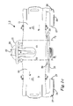
- FIG. 1 a is a view in perspective of the bike carrier 2
- figure 1 b shows the bike carrier 2 with a view towards the front of the bike carrier 2, i.e. with a view towards the license plate holder
- figure 1 c shows the bike carrier with a view from above.
- the bike carrier 2 comprises a first and a second load receiving section 10, 11, each comprising a load receiving surface 12, 13.
- the first and the second load receiving sections 10, 11 are pivotally mounted to a frame member 20 comprising a tow bar coupling 22 (not shown) adapted to be mounted to the tow bar of the vehicle.
- the first and the second load receiving sections 10, 11 thus are thus adapted to pivot about a first and a second pivot axis P1, P2 respectively; indicated with dashed lines in figure 1c .
- the tow bar coupling 22 is of a standard type comprising a socket adapted to receive and connect to a ball of the towing hook of the vehicle to form a ball and socket joint and is best shown in figure 1c .
- the first and the second load receiving sections 10, 11 are arranged substantially aligned in a side-by side manner.
- the frame member 20 further comprises a U-formed bar 21 to which one or more bikes can be coupled, optionally via securing members such as lines, attachment arms or the like, for providing support and stability during transportation, i.e. a load support bar.
- a bicycle can thus be positioned on the load carrier 1 with one wheel on each load receiving section and then further be supported via the U formed bar 21.
- the wheels of the bicycle may further be attached to the load receiving sections respectively.
- a first and a second rear light 24, 25 is arranged on the first and the second load receiving section respectively of the bike carrier 2, and are powered by the electrical system of the vehicle via e.g. a cord.
- the first and the second rear lights 24, 25 each comprises a proximal end 26 and a distal end 27, and is attached to the respective load receiving section 10, 11 at the proximal end 26.
- the first and the second rear lights 24, 25 extends substantially parallel with the extension of the first and the second load receiving sections 10, 11.
- the first and the second rear lights 24, 25 are further separated a distance from the first and the second load receiving sections 10, 11 of about 1-10 cm, advantageously 2-7 cm, or an appropriate distance adapted for the license plate holder 30 and an attached license plate (not shown) to fit there between.
- the bike carrier comprises a license plate holder 30.
- the license plate holder 30 enables a user to connect, or attach, a vehicle license plate to the license plate holder 30.
- the license plate holder 30 is attached to both the first and the second load receiving section 10, 11, and in the shown embodiment, pivotally connected to the first and the second load receiving sections 10, 11 at a first and a second pivot point 31, 32.
- the first pivot point 31 is in the shown embodiment a fix pivot point with respect to the license plate holder 30 and connects the license plate holder 30 with the first load receiving section.
- the first pivot point 31 comprises a pin 35, in this case a screw 36 which attaches the license plate holder 30 to the first load receiving section 10.
- the second connection point 32 formed by a second pin 37, formed by a screw 38, connecting the license plate holder 3 to the second load receiving section 11.
- a first and a second bushing 39 distance the license plate holder 30 from the first and the second load receiving section 10, 11.
- the license plate holder 309 comprises a guiding track 40, in the form of a slot 41.
- the slot 41 is formed by an elongated aperture extending through the whole of the thickness of the license plate holder 30.
- the guiding track 40 could be a groove, formed by protruding elements, or similar. The important feature is that the guiding track 40 provides for guiding means to the second pin 37 for reasons as will be described herein.
- the license plate holder 30 has a substantially rectangular form having a first and a second transverse side 30a, 3b, and a first and a second longitudinal side 30c, 30d.
- the first longitudinal side 30c is intended to be an upper longitudinal side
- the second longitudinal side 30d is intended to be a lower ground facing side, when the bike carrier is mounted to a vehicle as intended and being positioned in the carrier position.
- the guiding track 40 has arc shaped form comprising a first and a second crest 41, 42 and extending substantially between the first and the second longitudinal sides 30c, 30d of the license plate holder 30. It should be noted that the guiding track 40 can have other forms such as a straight line, an arc shaped form with only one crest, etc. The shape and form of the guiding track 40 is determined by the appropriate rotational path which the license plate holder 30 is intended to follow.
- FIGs 2a-2c shows the bike carrier 2 of figure 1 as the bike carrier 2 is transferred from the carrier position, shown in figures 1a-1c , to the storage position, shown in figure 3 .
- FIGs 2a-2c shows the bike carrier 2 in intermediate positions between the carrier position and the storage position.
- the transformation of the bike carrier 2 will be described in greater detail with reference to figures 2a-2c .
- the second load receiving section 11 is pivoted about the pivot axis P2, e.g. by a user.
- the second pivot point 32 slides along the guiding track 40 as the license plate holder 30 pivots about the first pivot point 31 due to the displacement of the second load receiving section 11.
- the second load receiving section 11 has been displaced to a substantially vertical position and is substantially aligned with the main extension of the U-formed bar 21 of the frame member 20.
- the second load receiving section 11 is now positioned in the storage position.
- the license plate holder 30 is only angled with an angle of about 45 degrees with respect to the original position of the second load receiving section 11, i.e. the position which the second load receiving section had in the carrier position.
- the second pivot point 32 is now substantially in the middle of the guiding track 40.
- the arc shaped form of the guiding track 40 changes transform from a convex form CX to a concave form CV at this point so that the second pivot point 32 is displaced along the concave form CV for the remaining section of the guiding track 40.
- the first crest 41 is thus on the concave formed CV section of the guiding track 40 and the second crest, which is pointing in the opposite direction to the first crest 41, is on the convex CX section of the guiding track 40.
- the license plate holder 30 pivots the remaining portion to a substantially vertical position as seen in figure 3 .
- the first and the second load receiving sections 10, 11 are positioned in the storage position, the license plate holder is positioned in the storage position, and the bike holder 2 is thus in the storage position.
- the first and the second rear lights 24, 25 each comprises a proximal end 26 and a distal end 27.
- the second transverse end 30b of the license plate holder 30 will be inserted between the first and the second rear light, and the first and the second load receiving sections 10, 11, thus providing a very compact sized storage form of the bike carrier 2.
- both the first and the second pivot points 31, 32 could be displaceable to some extent.
- the principle described above with a pin member and a guiding track can also be used for the first pivot point dependent on how the license plate holder is intended to be pivoted with the first and the second load receiving sections 10, 11.
- the license plate holder 30 could thus be arranged with one or more guiding tracks e.g. two guiding tracks. Each pivot point could have a guiding track. It is also conceivable that one pivot point has two guiding tracks; the pivot direction of the license plate holder 30 could in this case be changed when a user changes guiding track. In this way it is possible that the license plate holder 30 is substantially horizontal, as shown in figures 1 a-1 c , while the first and the second load receiving sections 10, 11 are arranged in the storage position, as shown in figure 3 .
- the license plate holder 30 can be attached to one of the load receiving sections 10, 11 only.
- the license plate holder 30 could be attached via the first pivot point 31.
- the license plate holder 30 could be made to rotate via a gear wheel arrangement.
- Figure 4 shows in a schematic manner, parts of the frame member 20, parts of the first load receiving section 10, the first pivot axis P1.
- Figure 4 further shows a gear wheel arrangement 50.
- the gear wheel arrangement 50 comprises a first bevel gear 51 rotably connected to the frame member 20 and aligned with the first pivot axis P1, a second bevel gear 52 rotably arranged on the first load receiving section 10.
- the second bevel gear 52 is arranged on a shaft 53 which transfers the rotational motion to a third bevel gear 54.
- the shaft 53 is arranged inside of the first load receiving section 10 so as to reduce the risk of interference with any load deployed on the load receiving surface 12 of the load receiving section 10, and thus indicated with dashed lines in figure 4 .
- the shaft 53 is arranged substantially perpendicular to the first pivot axis P1.
- a forth bevel gear 55 transfers the rotation to the license plate holder 30 via a second shaft 56.
- the second shaft 56 forms a pivot axis for the license plate holder 30.
- the angle of rotation that the license plate holder 30 will rotate is determined by the diameter of the bevel gears, the rotation direction can be changed by adding a second gear wheel between the third and the forth bevel gear 54, 55 is desirable. In this way, the license plate holder 30 can be made to rotate to a desired position, e.g. as seen in figure 3 using only one pivot point.
- the license plate holder 30 could be pivotally connected at a first pivot point to the first load receiving section attached to the second load receiving section via a string, strap or other flexible and/or elastic elongated element. This is schematically indicated in figure 1 a by reference 60.
- the license plate holder 30 can thus be automatically pivoted and positioned in a storage position by simply displacing one or more of the load receiving sections.
- the displacement of the one or more of the load receiving sections can be done manually by a user or via an electrical motor upon a user issued command.
Abstract
Description
- The present invention relates to a load carrier for a vehicle, such as a sports equipment carrier e.g. a bike carrier, adapted to be coupled to a towing hook of a vehicle. The load carrier can be positioned in a carrier position in which it can receive and carry a load, and a storage position, in which it has a more compact form, enabling it to be stored in an effective manner. The load carrier has a license plate holder which can be tucked away in a convenient manner.
- Load carriers, e.g. sports equipment carriers, e.g. bicycle carriers, also referred to as bike carriers, can usually be coupled to the rear of a vehicle by being coupled to a towing hook of the vehicle. As such they usually tend to obstruct the rear lights of the vehicle. By law, in many countries, the rear lights of the vehicle must be properly displayed to third parties, and is thus not permitted to be obstructed from view. The same applies for the vehicle license plate, sometimes also referred to as the vehicle registration plate. Load carriers may thus be provided with lights and a license plate holder.
- The European Patent No.
EP 1,539,537 B1 , Thule Sweden AB, disclose a load carrier for carrying a bicycle, which is foldable to make the load carrier smaller permitting it to be tucked away and stored in an easy manner. The load carrier has two foldable portions and a middle portion onto which a license plate holder is positioned. - Load carriers of the above mentioned type has some drawbacks. After being folded it is still somewhat bulky and does not provide for a load carrier which is relatively small and compact when ready for storage. It is an object of the present invention to reduce the drawbacks of the above mentioned load carrier, or at least to provide for an improved load carrier, or at least to provide for a useful alternative. The objects of the present inventions are met by a load carrier for a vehicle, preferably adapted to be coupled to a towing hook of the vehicle. The load carrier comprises a first load receiving section, a second load receiving section, the first and second load receiving sections being pivotally connected permitting the first and the second load receiving sections to be positioned in an carrier position and a storage position. The load carrier comprises a license plate holder. The license plate holder is pivotally connected to at least one of the first or the second load receiving section, so that the license plate holder can be pivoted to the storage position via the displacement of at least one of the first or the second load receiving sections.
- The load carrier provides for a load carrier which can be folded into a small and compact load carrier which can be stored in a convenient manner, even if the load carrier is provided with a license plate via the license plate holder. The license plate holder can be automatically pivoted and positioned in a storage position by simply displacing one or more of the load receiving sections. This is a very comfortable way of turning the load carrier to a relatively compact size for storage, or just to reduce the wind resistance if no load is carried on the load carrier.
- The load carrier can be specifically adapted to be positioned on the rear of the vehicle, e.g. provided with a connection site for connecting to a towing hook of the vehicle.
- The license plate holder can be configured to pivot in different ways. For example, the license plate holder can be pivotally connected to the first load receiving section at a first pivot point, the first pivot point having a fixed position with respect to the license plate holder and the first load receiving section. This will enable the license plate holder to pivot about that pivot point in a controlled manner.
- Advantageously, the license plate holder is pivotally connected to the second load receiving section at a second pivot point and, the second pivot point is displaceable with respect to the license plate holder or the second load receiving section. This provides for the license plate holder to pivot in a controlled manner, i.e. the pivot path can be controlled by manipulating the displacement of the second pivot point. In fact, the pivot path can be controlled by manipulating the displacement of any of the pivot points to a desired pivot path.
- According to an aspect, the second pivot point is displaceable with respect to the license plate holder. Optionally, the second pivot point is displaceable with respect to the second load receiving section. For example, if the second pivot point is formed by a pin member which can be displaced din a guiding track. The pin member can be arranged on the license plate holder and the guiding track can be arranged on the second load receiving section, or vice versa.
- According to an aspect, the guiding track is formed by a groove, a slot, or at least one protruding element. The guiding track can have different forms and elongations. The guiding track can be formed by parts of the license plate holder, e.g. the one of the longitudinal sides of the license plate holder, or by a slot, groove, or protruding element on the license plate holder.
- It should be noted that the size of license plate holder can vary. In the described embodiments herein the size of the license plate holder substantially corresponds to the size of a license plate in a European country, such as Sweden. However, the size and shape of the license plate holder can be formed to fit any license plate. It is also conceivable that the license plate holder is significantly smaller than the license plate itself, the important aspect is that a pivotal motion can be transferred to the license plate holder, and thus the license plate. This will enable the bike carrier to be small and compact when positioned in the storage position.
- According to an aspect, the guiding track has a curved form. Such curved form can comprises at least one crest, two crests or more.
- According to an aspect, when the first and the second load receiving section is positioned in the storage position, the first and the second load receiving section are positioned substantially adjacent each other.
- According to an aspect, when the first and the second load receiving sections are positioned in the storage position, the first and the second load receiving sections are substantially parallel with a vertical axis.
- According to an aspect, the first and the second load receiving sections comprises a first and a second load receiving surface. The first and the second load receiving surfaces are positioned facing each other when the load carrier is positioned in the storage position. According to an aspect, when the first and the second load receiving sections are positioned in the carrier position, the first and the second load receiving sections are positioned in a folded out, side-by-side position.
- According to an aspect, when the first and the second load receiving sections are positioned in the storage position, the first and the second load receiving sections are aligned along a horizontal axis.
- Non-limiting embodiments of the present invention will be described in greater detail with reference to the accompanying figures in which;
-
figure 1a is a view in perspective of a load carrier according to an embodiment; -
figure 1b shows the load carrier offigure 1a with a view towards the license plate holder; -
figure 1c shows the load carrier offigure 1 a with a view towards the first and the second load receiving sections and from above; -
figures 2a-2c show the load carrier in different positions between the carrier position and the storage position; -
figure 3 shows the load carrier in the storage position and; -
figure 4 shows an embodiment of a pivot mechanism for pivoting the license plate holder during displacement of the first load receiving section. -
Figures 1a-1c shows a load carrier 1 for a vehicle (not shown) adapted to be attached to a towing hook of the vehicle. The load carrier is in the shown embodiments a bicycle carrier 2, in this case adapted to carry two bicycles. Instead of carrying bikes, the load carrier could carry luggage, sports equipment such as surfboards, skies, or any other load usable to man. - The bike carrier 2 can be positioned in a carrier position, as shown in
figures 1a-1c in which the bike carrier 2 can receive and carry a bike for transportation, and a storage position, in which the bike carrier 2 can be put away for storage. The bike carrier 2 is foldable; it can be pivoted, between a carrier position and a storage position. In the storage position, the bike carrier could possibly be transported on the towing hook of the vehicle but it cannot be used for transporting bicycles to the same extent as when being in the carrier position. - In the following, the bike carrier 2 will be described in greater detail with reference to the
figures 1 a-1 c in whichfigure 1 a is a view in perspective of the bike carrier 2;figure 1 b shows the bike carrier 2 with a view towards the front of the bike carrier 2, i.e. with a view towards the license plate holder, and;figure 1 c shows the bike carrier with a view from above. The bike carrier 2 comprises a first and a secondload receiving section load receiving surface load receiving sections frame member 20 comprising a tow bar coupling 22 (not shown) adapted to be mounted to the tow bar of the vehicle. The first and the secondload receiving sections figure 1c . Thetow bar coupling 22 is of a standard type comprising a socket adapted to receive and connect to a ball of the towing hook of the vehicle to form a ball and socket joint and is best shown infigure 1c . Infigure 1a the first and the secondload receiving sections frame member 20 further comprises aU-formed bar 21 to which one or more bikes can be coupled, optionally via securing members such as lines, attachment arms or the like, for providing support and stability during transportation, i.e. a load support bar. A bicycle can thus be positioned on the load carrier 1 with one wheel on each load receiving section and then further be supported via the U formedbar 21. The wheels of the bicycle may further be attached to the load receiving sections respectively. - A first and a second
rear light rear lights proximal end 26 and adistal end 27, and is attached to the respectiveload receiving section proximal end 26. The first and the secondrear lights load receiving sections rear lights load receiving sections license plate holder 30 and an attached license plate (not shown) to fit there between. - The bike carrier comprises a
license plate holder 30. Thelicense plate holder 30 enables a user to connect, or attach, a vehicle license plate to thelicense plate holder 30. Thelicense plate holder 30 is attached to both the first and the secondload receiving section load receiving sections second pivot point - The
first pivot point 31 is in the shown embodiment a fix pivot point with respect to thelicense plate holder 30 and connects thelicense plate holder 30 with the first load receiving section. Thefirst pivot point 31 comprises apin 35, in this case ascrew 36 which attaches thelicense plate holder 30 to the firstload receiving section 10. In a similar manner is thesecond connection point 32 formed by asecond pin 37, formed by ascrew 38, connecting the license plate holder 3 to the secondload receiving section 11. A first and asecond bushing 39 distance thelicense plate holder 30 from the first and the secondload receiving section - The
second pivot point 32 is displaceable with respect to thelicense plate holder 30. As can be seen infigures 1a-1b , the license plate holder 309 comprises a guidingtrack 40, in the form of aslot 41. Theslot 41 is formed by an elongated aperture extending through the whole of the thickness of thelicense plate holder 30. Optionally, the guidingtrack 40 could be a groove, formed by protruding elements, or similar. The important feature is that the guidingtrack 40 provides for guiding means to thesecond pin 37 for reasons as will be described herein. - The
license plate holder 30 has a substantially rectangular form having a first and a secondtransverse side 30a, 3b, and a first and a secondlongitudinal side longitudinal side 30c is intended to be an upper longitudinal side, and the secondlongitudinal side 30d is intended to be a lower ground facing side, when the bike carrier is mounted to a vehicle as intended and being positioned in the carrier position. - The guiding
track 40 has arc shaped form comprising a first and asecond crest longitudinal sides license plate holder 30. It should be noted that the guidingtrack 40 can have other forms such as a straight line, an arc shaped form with only one crest, etc. The shape and form of the guidingtrack 40 is determined by the appropriate rotational path which thelicense plate holder 30 is intended to follow. -
Figures 2a-2c shows the bike carrier 2 offigure 1 as the bike carrier 2 is transferred from the carrier position, shown infigures 1a-1c , to the storage position, shown infigure 3 . -
Figures 2a-2c shows the bike carrier 2 in intermediate positions between the carrier position and the storage position. The transformation of the bike carrier 2 will be described in greater detail with reference tofigures 2a-2c . Infigure 2a , the secondload receiving section 11 is pivoted about the pivot axis P2, e.g. by a user. As is noted, thesecond pivot point 32 slides along the guidingtrack 40 as thelicense plate holder 30 pivots about thefirst pivot point 31 due to the displacement of the secondload receiving section 11. Infigure 2b the secondload receiving section 11 has been displaced to a substantially vertical position and is substantially aligned with the main extension of theU-formed bar 21 of theframe member 20. The secondload receiving section 11 is now positioned in the storage position. However, as is noticed, thelicense plate holder 30 is only angled with an angle of about 45 degrees with respect to the original position of the secondload receiving section 11, i.e. the position which the second load receiving section had in the carrier position. Thesecond pivot point 32 is now substantially in the middle of the guidingtrack 40. As is further noticed, the arc shaped form of the guidingtrack 40 changes transform from a convex form CX to a concave form CV at this point so that thesecond pivot point 32 is displaced along the concave form CV for the remaining section of the guidingtrack 40. Thefirst crest 41 is thus on the concave formed CV section of the guidingtrack 40 and the second crest, which is pointing in the opposite direction to thefirst crest 41, is on the convex CX section of the guidingtrack 40. - As the first
load receiving section 10 is displaced towards its storage position, as indicated by the arrow infigure 2c , thelicense plate holder 30 pivots the remaining portion to a substantially vertical position as seen infigure 3 . Infigure 3 , the first and the secondload receiving sections - Turning back to
figure 1c , the first and the secondrear lights proximal end 26 and adistal end 27. As thelicense plate holder 30 is pivoted, the secondtransverse end 30b of thelicense plate holder 30 will be inserted between the first and the second rear light, and the first and the secondload receiving sections - In an embodiment, both the first and the second pivot points 31, 32 could be displaceable to some extent. The principle described above with a pin member and a guiding track can also be used for the first pivot point dependent on how the license plate holder is intended to be pivoted with the first and the second
load receiving sections license plate holder 30 could thus be arranged with one or more guiding tracks e.g. two guiding tracks. Each pivot point could have a guiding track. It is also conceivable that one pivot point has two guiding tracks; the pivot direction of thelicense plate holder 30 could in this case be changed when a user changes guiding track. In this way it is possible that thelicense plate holder 30 is substantially horizontal, as shown infigures 1 a-1 c , while the first and the secondload receiving sections figure 3 . - According one embodiment, the
license plate holder 30 can be attached to one of theload receiving sections license plate holder 30 could be attached via thefirst pivot point 31. Thelicense plate holder 30 could be made to rotate via a gear wheel arrangement. One such embodiment is shown infigure 4. Figure 4 shows in a schematic manner, parts of theframe member 20, parts of the firstload receiving section 10, the first pivot axis P1.Figure 4 further shows agear wheel arrangement 50. Thegear wheel arrangement 50 comprises afirst bevel gear 51 rotably connected to theframe member 20 and aligned with the first pivot axis P1, asecond bevel gear 52 rotably arranged on the firstload receiving section 10. Thesecond bevel gear 52 is arranged on ashaft 53 which transfers the rotational motion to athird bevel gear 54. Theshaft 53 is arranged inside of the firstload receiving section 10 so as to reduce the risk of interference with any load deployed on theload receiving surface 12 of theload receiving section 10, and thus indicated with dashed lines infigure 4 . Theshaft 53 is arranged substantially perpendicular to the first pivot axis P1. A forthbevel gear 55 transfers the rotation to thelicense plate holder 30 via asecond shaft 56. Thesecond shaft 56 forms a pivot axis for thelicense plate holder 30. As the firstload carrying section 10 is displaced from the carrier position, as seen infigure 1a for example, to the storage position, as seen infigure 3 , thelicense plate holder 30 will rotate. The angle of rotation that thelicense plate holder 30 will rotate is determined by the diameter of the bevel gears, the rotation direction can be changed by adding a second gear wheel between the third and theforth bevel gear license plate holder 30 can be made to rotate to a desired position, e.g. as seen infigure 3 using only one pivot point. - As another alternative, to a guiding track above and a second pivot point, the
license plate holder 30 could be pivotally connected at a first pivot point to the first load receiving section attached to the second load receiving section via a string, strap or other flexible and/or elastic elongated element. This is schematically indicated infigure 1 a byreference 60. - The
license plate holder 30 can thus be automatically pivoted and positioned in a storage position by simply displacing one or more of the load receiving sections. The displacement of the one or more of the load receiving sections can be done manually by a user or via an electrical motor upon a user issued command.
Claims (15)
- A load carrier (1, 2) for a vehicle comprising
a first load receiving section (10),
a second load receiving section (11),
said first and second load receiving sections (10, 11) being pivotally connected permitting said first and said second load receiving sections (10, 11) to be positioned in an carrier position and a storage position,
said load carrier (1, 2) further comprising a license plate holder (30), characterized in that
said license plate holder (30) is pivotally connected to at least one of said first or
said second load receiving sections (10, 11), so that said license plate holder (30) can be pivoted to said storage position via the displacement of at least one of said first or second load receiving sections (10, 11). - The load carrier (1, 2) according to claim 1, wherein said license plate holder (30) is pivotally connected to said first and said first or said second load receiving sections (10, 11).
- The load carrier (1, 2) according to claim 1 or 2, wherein said license plate holder (30) is pivotally connected to said first load receiving sections (10, 11) at a first pivot point (31), said first pivot point (31) having a fixed position with respect to said license plate holder (30) and said first load receiving section (10).
- The load carrier (1, 2) according to any one of the preceding claims, wherein said license plate holder (30) is pivotally connected to said second load receiving section (11) at a second pivot point (32) and, said second pivot point (32) is displaceable with respect to said license plate holder (30) or said second load receiving section (11).
- The load carrier (1, 2) according to claim 4, wherein said second pivot point (32) is displaceable with respect to said license plate holder (30).
- The load carrier (1, 2) according to claim 4, wherein said license plate holder (30) and said second pivot point (32) is displaceable with respect to said second load receiving section (11).
- The load carrier (1, 2) according to any one of the preceding claims, wherein said second pivot point (32) is formed by a pin member (37, 38) displaceable in a guiding track (40).
- The load carrier (1, 2) according to claim 7, wherein said guiding track (40) is formed by a groove, a slot, and/or at least one protruding element of said license plate holder (30), or by a side of the license plate holder (30d).
- The load carrier (1, 2) according to claim 8, wherein said guiding track (40) has a curved form.
- The load carrier (1, 2) according to claim 9, wherein said curved form of said guiding track (40) comprises a first and a second crest (41, 42).
- The load carrier (1, 2) according to any one of the preceding claims, wherein said first and said second load receiving sections (10, 11) comprises a first and a second load receiving surface (12, 13), and in that said first and said second load receiving surface (12, 13) are positioned facing each other, when said load carrier (1, 2) is positioned in said storage position.
- The load carrier (1, 2) according to claim 11, wherein when said first and said second load receiving sections (10, 11) are positioned in said storage position, said first and said second load receiving sections (10, 11) are substantially parallel with a vertical axis.
- The load carrier (1, 2) according to any one of the preceding claims, wherein when said first and said second load receiving sections (10, 11) are positioned in said carrier position, said first and said second load receiving sections (10, 11) are positioned in a folded out, side-by-side configuration.
- The load carrier (1, 2) according to claim 13, wherein said first and said second load receiving sections (10, 11) are positioned in said storage position, said first and said second load receiving sections (10, 11) are substantially aligned along a horizontal axis.
- The load carrier (1, 2) according to any one of the preceding claims, wherein said load carrier (1, 2) comprises a connection site (22) for connecting to a towing hook of said vehicle.
Priority Applications (3)
| Application Number | Priority Date | Filing Date | Title |
|---|---|---|---|
| EP12168494.8A EP2664497B2 (en) | 2012-05-18 | 2012-05-18 | Load carrier for a vehicle |
| CN201380025959.4A CN104284810B (en) | 2012-05-18 | 2013-05-17 | For the load carrier of vehicle |
| PCT/EP2013/060241 WO2013171328A1 (en) | 2012-05-18 | 2013-05-17 | Load carrier for a vehicle |
Applications Claiming Priority (1)
| Application Number | Priority Date | Filing Date | Title |
|---|---|---|---|
| EP12168494.8A EP2664497B2 (en) | 2012-05-18 | 2012-05-18 | Load carrier for a vehicle |
Publications (3)
| Publication Number | Publication Date |
|---|---|
| EP2664497A1 true EP2664497A1 (en) | 2013-11-20 |
| EP2664497B1 EP2664497B1 (en) | 2015-05-06 |
| EP2664497B2 EP2664497B2 (en) | 2018-04-11 |
Family
ID=48464004
Family Applications (1)
| Application Number | Title | Priority Date | Filing Date |
|---|---|---|---|
| EP12168494.8A Active EP2664497B2 (en) | 2012-05-18 | 2012-05-18 | Load carrier for a vehicle |
Country Status (3)
| Country | Link |
|---|---|
| EP (1) | EP2664497B2 (en) |
| CN (1) | CN104284810B (en) |
| WO (1) | WO2013171328A1 (en) |
Cited By (7)
| Publication number | Priority date | Publication date | Assignee | Title |
|---|---|---|---|---|
| USD811985S1 (en) * | 2016-05-26 | 2018-03-06 | Thule Sweden Ab | Carrier |
| USD813784S1 (en) * | 2016-07-11 | 2018-03-27 | Thule Sweden Ab | Carrier |
| BE1026014B1 (en) * | 2018-08-22 | 2019-09-06 | Hermanos Sanchez Lafuente S.A. | Tilt device for license plate holders of bicycle carriers |
| USD873758S1 (en) | 2018-07-20 | 2020-01-28 | Thule Sweden Ab | Carrier |
| EP3656610A1 (en) * | 2018-11-23 | 2020-05-27 | Carman Enterprise Co., Ltd. | Rear load carrier |
| IT202100002060A1 (en) * | 2021-02-02 | 2021-05-02 | Aurilis Group Italia S R L | Foldable device for transporting a load on motor vehicles |
| WO2023287288A1 (en) | 2021-07-15 | 2023-01-19 | Indes Holding B.V. | Bicycle carrier |
Families Citing this family (4)
| Publication number | Priority date | Publication date | Assignee | Title |
|---|---|---|---|---|
| CA2945937C (en) | 2014-04-22 | 2022-04-05 | Macchiavelli S.R.L. | Capsule for infusion products, in particular coffee |
| DE102015208797B4 (en) * | 2015-05-12 | 2021-12-16 | Uebler Gmbh | Load carrier for a motor vehicle |
| DE102015208798B4 (en) * | 2015-05-12 | 2021-07-15 | Uebler Gmbh | Load carrier for a motor vehicle |
| GB2588911B (en) | 2019-11-13 | 2022-06-15 | Noko Design Tech Manufacture Ltd | Modular carrying system |
Citations (4)
| Publication number | Priority date | Publication date | Assignee | Title |
|---|---|---|---|---|
| DE10144550A1 (en) * | 2001-09-10 | 2003-04-03 | Hs Products Karosseriesysteme | Rear end load carrier has one carrier part pivoted to another and carrier element across one or both of them |
| DE10257903A1 (en) * | 2002-12-11 | 2004-06-24 | Webasto Vehicle Systems International Gmbh | Retractable load carrier for rear end of automobile fitting into reception space together with additional components used with load carrier in its working position |
| EP1539537B1 (en) | 2002-07-08 | 2006-11-22 | Thule Sweden AB | Load carrier |
| EP2017131A2 (en) * | 2007-07-11 | 2009-01-21 | WESTFALIA - Automotive GmbH | Load carrier for a motor vehicle |
Family Cites Families (3)
| Publication number | Priority date | Publication date | Assignee | Title |
|---|---|---|---|---|
| CA2162873A1 (en) | 1993-05-25 | 1994-12-08 | Ken John Bryan | Bicyle rack |
| DE102008046574A1 (en) * | 2008-09-10 | 2010-03-11 | GM Global Technology Operations, Inc., Detroit | Luggage carrier arrangement for a vehicle rear |
| DE102012103697A1 (en) | 2012-04-26 | 2013-10-31 | I-RACKS GmbH | Collapsible load carrier with extension kit for attachment to a trailer hitch of a motor vehicle |
-
2012
- 2012-05-18 EP EP12168494.8A patent/EP2664497B2/en active Active
-
2013
- 2013-05-17 CN CN201380025959.4A patent/CN104284810B/en active Active
- 2013-05-17 WO PCT/EP2013/060241 patent/WO2013171328A1/en active Application Filing
Patent Citations (4)
| Publication number | Priority date | Publication date | Assignee | Title |
|---|---|---|---|---|
| DE10144550A1 (en) * | 2001-09-10 | 2003-04-03 | Hs Products Karosseriesysteme | Rear end load carrier has one carrier part pivoted to another and carrier element across one or both of them |
| EP1539537B1 (en) | 2002-07-08 | 2006-11-22 | Thule Sweden AB | Load carrier |
| DE10257903A1 (en) * | 2002-12-11 | 2004-06-24 | Webasto Vehicle Systems International Gmbh | Retractable load carrier for rear end of automobile fitting into reception space together with additional components used with load carrier in its working position |
| EP2017131A2 (en) * | 2007-07-11 | 2009-01-21 | WESTFALIA - Automotive GmbH | Load carrier for a motor vehicle |
Cited By (10)
| Publication number | Priority date | Publication date | Assignee | Title |
|---|---|---|---|---|
| USD811985S1 (en) * | 2016-05-26 | 2018-03-06 | Thule Sweden Ab | Carrier |
| USD813784S1 (en) * | 2016-07-11 | 2018-03-27 | Thule Sweden Ab | Carrier |
| USD873758S1 (en) | 2018-07-20 | 2020-01-28 | Thule Sweden Ab | Carrier |
| BE1026014B1 (en) * | 2018-08-22 | 2019-09-06 | Hermanos Sanchez Lafuente S.A. | Tilt device for license plate holders of bicycle carriers |
| GB2576581A (en) * | 2018-08-22 | 2020-02-26 | Lafuente Hermanos S Sa | A folding device for number plate holder on bicycle rack |
| EP3656610A1 (en) * | 2018-11-23 | 2020-05-27 | Carman Enterprise Co., Ltd. | Rear load carrier |
| IT202100002060A1 (en) * | 2021-02-02 | 2021-05-02 | Aurilis Group Italia S R L | Foldable device for transporting a load on motor vehicles |
| WO2022168133A1 (en) * | 2021-02-02 | 2022-08-11 | Aurilis Group Italia S.R.L. | Foldable device for transporting bicycles on motor vehicles |
| WO2023287288A1 (en) | 2021-07-15 | 2023-01-19 | Indes Holding B.V. | Bicycle carrier |
| NL2028733B1 (en) | 2021-07-15 | 2023-01-20 | Indes Holding Bv | Bicycle carrier |
Also Published As
| Publication number | Publication date |
|---|---|
| CN104284810A (en) | 2015-01-14 |
| EP2664497B1 (en) | 2015-05-06 |
| EP2664497B2 (en) | 2018-04-11 |
| WO2013171328A1 (en) | 2013-11-21 |
| CN104284810B (en) | 2016-05-18 |
Similar Documents
| Publication | Publication Date | Title |
|---|---|---|
| EP2664497B1 (en) | Load carrier for a vehicle | |
| US8894084B1 (en) | Compact folding bicycle | |
| US6979013B2 (en) | Bicycle foldable to align front and rear wheels along a transverse direction of the bicycle | |
| US8505932B1 (en) | Bicycle hauler | |
| US7806307B2 (en) | Carrier device for a bicycle | |
| US7445224B2 (en) | Folding bicycle | |
| US9211898B2 (en) | Golf trolley | |
| US11097801B2 (en) | Scooter having an element that can be attached or that is connected in an articulated manner | |
| US9744910B2 (en) | Foldable load carrier with a latching brace | |
| EP3024702A1 (en) | Convertible mounting bracket | |
| US20110079621A1 (en) | Carrier racks for vehicles | |
| CN102271991A (en) | Articulation device for the steering column of a cycle | |
| DE202020103807U1 (en) | Rear rack | |
| US10870460B2 (en) | Compact folding electric bicycle | |
| US20080143067A1 (en) | Device for controlling wheeled vehicles, wheeled vehicles incorporating such device and methods of operating the same | |
| CA2494292A1 (en) | Articulated handlebar riser block for recreational vehicles | |
| GB2512096A (en) | Carrier assembly for a motorized vehicle | |
| US9481417B2 (en) | Modular trailer assembly | |
| US10889229B2 (en) | Vehicle rack | |
| US7503574B1 (en) | Bicycle caddie | |
| CA3039578A1 (en) | Rear vehicle rack and davit system | |
| US9233648B2 (en) | Bicycle rack | |
| US20160288602A1 (en) | Convertible cargo carrier and cart system accessories | |
| JP2009107608A (en) | Collapsible bicycle | |
| CN117769514A (en) | Bicycle trailer |
Legal Events
| Date | Code | Title | Description |
|---|---|---|---|
| PUAI | Public reference made under article 153(3) epc to a published international application that has entered the european phase |
Free format text: ORIGINAL CODE: 0009012 |
|
| AK | Designated contracting states |
Kind code of ref document: A1 Designated state(s): AL AT BE BG CH CY CZ DE DK EE ES FI FR GB GR HR HU IE IS IT LI LT LU LV MC MK MT NL NO PL PT RO RS SE SI SK SM TR |
|
| AX | Request for extension of the european patent |
Extension state: BA ME |
|
| 17P | Request for examination filed |
Effective date: 20140428 |
|
| RBV | Designated contracting states (corrected) |
Designated state(s): AL AT BE BG CH CY CZ DE DK EE ES FI FR GB GR HR HU IE IS IT LI LT LU LV MC MK MT NL NO PL PT RO RS SE SI SK SM TR |
|
| TPAC | Observations filed by third parties |
Free format text: ORIGINAL CODE: EPIDOSNTIPA |
|
| GRAP | Despatch of communication of intention to grant a patent |
Free format text: ORIGINAL CODE: EPIDOSNIGR1 |
|
| INTG | Intention to grant announced |
Effective date: 20141017 |
|
| GRAS | Grant fee paid |
Free format text: ORIGINAL CODE: EPIDOSNIGR3 |
|
| GRAP | Despatch of communication of intention to grant a patent |
Free format text: ORIGINAL CODE: EPIDOSNIGR1 |
|
| INTG | Intention to grant announced |
Effective date: 20150310 |
|
| GRAA | (expected) grant |
Free format text: ORIGINAL CODE: 0009210 |
|
| AK | Designated contracting states |
Kind code of ref document: B1 Designated state(s): AL AT BE BG CH CY CZ DE DK EE ES FI FR GB GR HR HU IE IS IT LI LT LU LV MC MK MT NL NO PL PT RO RS SE SI SK SM TR |
|
| REG | Reference to a national code |
Ref country code: GB Ref legal event code: FG4D |
|
| REG | Reference to a national code |
Ref country code: CH Ref legal event code: EP |
|
| REG | Reference to a national code |
Ref country code: FR Ref legal event code: PLFP Year of fee payment: 4 |
|
| REG | Reference to a national code |
Ref country code: IE Ref legal event code: FG4D |
|
| REG | Reference to a national code |
Ref country code: AT Ref legal event code: REF Ref document number: 725447 Country of ref document: AT Kind code of ref document: T Effective date: 20150615 |
|
| REG | Reference to a national code |
Ref country code: DE Ref legal event code: R096 Ref document number: 602012007095 Country of ref document: DE Effective date: 20150618 |
|
| REG | Reference to a national code |
Ref country code: NL Ref legal event code: T3 |
|
| REG | Reference to a national code |
Ref country code: AT Ref legal event code: MK05 Ref document number: 725447 Country of ref document: AT Kind code of ref document: T Effective date: 20150506 |
|
| REG | Reference to a national code |
Ref country code: LT Ref legal event code: MG4D |
|
| PG25 | Lapsed in a contracting state [announced via postgrant information from national office to epo] |
Ref country code: ES Free format text: LAPSE BECAUSE OF FAILURE TO SUBMIT A TRANSLATION OF THE DESCRIPTION OR TO PAY THE FEE WITHIN THE PRESCRIBED TIME-LIMIT Effective date: 20150506 Ref country code: HR Free format text: LAPSE BECAUSE OF FAILURE TO SUBMIT A TRANSLATION OF THE DESCRIPTION OR TO PAY THE FEE WITHIN THE PRESCRIBED TIME-LIMIT Effective date: 20150506 Ref country code: LT Free format text: LAPSE BECAUSE OF FAILURE TO SUBMIT A TRANSLATION OF THE DESCRIPTION OR TO PAY THE FEE WITHIN THE PRESCRIBED TIME-LIMIT Effective date: 20150506 Ref country code: FI Free format text: LAPSE BECAUSE OF FAILURE TO SUBMIT A TRANSLATION OF THE DESCRIPTION OR TO PAY THE FEE WITHIN THE PRESCRIBED TIME-LIMIT Effective date: 20150506 Ref country code: PT Free format text: LAPSE BECAUSE OF FAILURE TO SUBMIT A TRANSLATION OF THE DESCRIPTION OR TO PAY THE FEE WITHIN THE PRESCRIBED TIME-LIMIT Effective date: 20150907 Ref country code: NO Free format text: LAPSE BECAUSE OF FAILURE TO SUBMIT A TRANSLATION OF THE DESCRIPTION OR TO PAY THE FEE WITHIN THE PRESCRIBED TIME-LIMIT Effective date: 20150806 |
|
| PG25 | Lapsed in a contracting state [announced via postgrant information from national office to epo] |
Ref country code: IS Free format text: LAPSE BECAUSE OF FAILURE TO SUBMIT A TRANSLATION OF THE DESCRIPTION OR TO PAY THE FEE WITHIN THE PRESCRIBED TIME-LIMIT Effective date: 20150906 Ref country code: LV Free format text: LAPSE BECAUSE OF FAILURE TO SUBMIT A TRANSLATION OF THE DESCRIPTION OR TO PAY THE FEE WITHIN THE PRESCRIBED TIME-LIMIT Effective date: 20150506 Ref country code: BG Free format text: LAPSE BECAUSE OF FAILURE TO SUBMIT A TRANSLATION OF THE DESCRIPTION OR TO PAY THE FEE WITHIN THE PRESCRIBED TIME-LIMIT Effective date: 20150806 Ref country code: RS Free format text: LAPSE BECAUSE OF FAILURE TO SUBMIT A TRANSLATION OF THE DESCRIPTION OR TO PAY THE FEE WITHIN THE PRESCRIBED TIME-LIMIT Effective date: 20150506 Ref country code: AT Free format text: LAPSE BECAUSE OF FAILURE TO SUBMIT A TRANSLATION OF THE DESCRIPTION OR TO PAY THE FEE WITHIN THE PRESCRIBED TIME-LIMIT Effective date: 20150506 Ref country code: GR Free format text: LAPSE BECAUSE OF FAILURE TO SUBMIT A TRANSLATION OF THE DESCRIPTION OR TO PAY THE FEE WITHIN THE PRESCRIBED TIME-LIMIT Effective date: 20150807 |
|
| REG | Reference to a national code |
Ref country code: CH Ref legal event code: PL |
|
| PG25 | Lapsed in a contracting state [announced via postgrant information from national office to epo] |
Ref country code: CH Free format text: LAPSE BECAUSE OF NON-PAYMENT OF DUE FEES Effective date: 20150531 Ref country code: DK Free format text: LAPSE BECAUSE OF FAILURE TO SUBMIT A TRANSLATION OF THE DESCRIPTION OR TO PAY THE FEE WITHIN THE PRESCRIBED TIME-LIMIT Effective date: 20150506 Ref country code: EE Free format text: LAPSE BECAUSE OF FAILURE TO SUBMIT A TRANSLATION OF THE DESCRIPTION OR TO PAY THE FEE WITHIN THE PRESCRIBED TIME-LIMIT Effective date: 20150506 Ref country code: IT Free format text: LAPSE BECAUSE OF FAILURE TO SUBMIT A TRANSLATION OF THE DESCRIPTION OR TO PAY THE FEE WITHIN THE PRESCRIBED TIME-LIMIT Effective date: 20150506 Ref country code: LI Free format text: LAPSE BECAUSE OF NON-PAYMENT OF DUE FEES Effective date: 20150531 |
|
| REG | Reference to a national code |
Ref country code: DE Ref legal event code: R026 Ref document number: 602012007095 Country of ref document: DE |
|
| PLBI | Opposition filed |
Free format text: ORIGINAL CODE: 0009260 |
|
| REG | Reference to a national code |
Ref country code: IE Ref legal event code: MM4A |
|
| PG25 | Lapsed in a contracting state [announced via postgrant information from national office to epo] |
Ref country code: RO Free format text: LAPSE BECAUSE OF NON-PAYMENT OF DUE FEES Effective date: 20150506 Ref country code: CZ Free format text: LAPSE BECAUSE OF FAILURE TO SUBMIT A TRANSLATION OF THE DESCRIPTION OR TO PAY THE FEE WITHIN THE PRESCRIBED TIME-LIMIT Effective date: 20150506 Ref country code: SK Free format text: LAPSE BECAUSE OF FAILURE TO SUBMIT A TRANSLATION OF THE DESCRIPTION OR TO PAY THE FEE WITHIN THE PRESCRIBED TIME-LIMIT Effective date: 20150506 Ref country code: PL Free format text: LAPSE BECAUSE OF FAILURE TO SUBMIT A TRANSLATION OF THE DESCRIPTION OR TO PAY THE FEE WITHIN THE PRESCRIBED TIME-LIMIT Effective date: 20150506 Ref country code: MC Free format text: LAPSE BECAUSE OF FAILURE TO SUBMIT A TRANSLATION OF THE DESCRIPTION OR TO PAY THE FEE WITHIN THE PRESCRIBED TIME-LIMIT Effective date: 20150506 |
|
| PLAX | Notice of opposition and request to file observation + time limit sent |
Free format text: ORIGINAL CODE: EPIDOSNOBS2 |
|
| 26 | Opposition filed |
Opponent name: STRAWMAN LIMITED Effective date: 20160204 |
|
| REG | Reference to a national code |
Ref country code: FR Ref legal event code: PLFP Year of fee payment: 5 |
|
| PG25 | Lapsed in a contracting state [announced via postgrant information from national office to epo] |
Ref country code: IE Free format text: LAPSE BECAUSE OF NON-PAYMENT OF DUE FEES Effective date: 20150518 |
|
| PG25 | Lapsed in a contracting state [announced via postgrant information from national office to epo] |
Ref country code: SI Free format text: LAPSE BECAUSE OF FAILURE TO SUBMIT A TRANSLATION OF THE DESCRIPTION OR TO PAY THE FEE WITHIN THE PRESCRIBED TIME-LIMIT Effective date: 20150506 |
|
| PLBB | Reply of patent proprietor to notice(s) of opposition received |
Free format text: ORIGINAL CODE: EPIDOSNOBS3 |
|
| PG25 | Lapsed in a contracting state [announced via postgrant information from national office to epo] |
Ref country code: MT Free format text: LAPSE BECAUSE OF FAILURE TO SUBMIT A TRANSLATION OF THE DESCRIPTION OR TO PAY THE FEE WITHIN THE PRESCRIBED TIME-LIMIT Effective date: 20150506 |
|
| REG | Reference to a national code |
Ref country code: FR Ref legal event code: PLFP Year of fee payment: 6 |
|
| PG25 | Lapsed in a contracting state [announced via postgrant information from national office to epo] |
Ref country code: SM Free format text: LAPSE BECAUSE OF FAILURE TO SUBMIT A TRANSLATION OF THE DESCRIPTION OR TO PAY THE FEE WITHIN THE PRESCRIBED TIME-LIMIT Effective date: 20150506 Ref country code: HU Free format text: LAPSE BECAUSE OF FAILURE TO SUBMIT A TRANSLATION OF THE DESCRIPTION OR TO PAY THE FEE WITHIN THE PRESCRIBED TIME-LIMIT; INVALID AB INITIO Effective date: 20120518 |
|
| PG25 | Lapsed in a contracting state [announced via postgrant information from national office to epo] |
Ref country code: CY Free format text: LAPSE BECAUSE OF FAILURE TO SUBMIT A TRANSLATION OF THE DESCRIPTION OR TO PAY THE FEE WITHIN THE PRESCRIBED TIME-LIMIT Effective date: 20150506 Ref country code: SE Free format text: LAPSE BECAUSE OF FAILURE TO SUBMIT A TRANSLATION OF THE DESCRIPTION OR TO PAY THE FEE WITHIN THE PRESCRIBED TIME-LIMIT Effective date: 20150506 |
|
| PG25 | Lapsed in a contracting state [announced via postgrant information from national office to epo] |
Ref country code: TR Free format text: LAPSE BECAUSE OF FAILURE TO SUBMIT A TRANSLATION OF THE DESCRIPTION OR TO PAY THE FEE WITHIN THE PRESCRIBED TIME-LIMIT Effective date: 20150506 |
|
| PG25 | Lapsed in a contracting state [announced via postgrant information from national office to epo] |
Ref country code: LU Free format text: LAPSE BECAUSE OF NON-PAYMENT OF DUE FEES Effective date: 20150518 |
|
| PUAH | Patent maintained in amended form |
Free format text: ORIGINAL CODE: 0009272 |
|
| STAA | Information on the status of an ep patent application or granted ep patent |
Free format text: STATUS: PATENT MAINTAINED AS AMENDED |
|
| 27A | Patent maintained in amended form |
Effective date: 20180411 |
|
| AK | Designated contracting states |
Kind code of ref document: B2 Designated state(s): AL AT BE BG CH CY CZ DE DK EE ES FI FR GB GR HR HU IE IS IT LI LT LU LV MC MK MT NL NO PL PT RO RS SE SI SK SM TR |
|
| REG | Reference to a national code |
Ref country code: DE Ref legal event code: R102 Ref document number: 602012007095 Country of ref document: DE |
|
| REG | Reference to a national code |
Ref country code: FR Ref legal event code: PLFP Year of fee payment: 7 |
|
| REG | Reference to a national code |
Ref country code: BE Ref legal event code: FP Effective date: 20150703 |
|
| PG25 | Lapsed in a contracting state [announced via postgrant information from national office to epo] |
Ref country code: MK Free format text: LAPSE BECAUSE OF FAILURE TO SUBMIT A TRANSLATION OF THE DESCRIPTION OR TO PAY THE FEE WITHIN THE PRESCRIBED TIME-LIMIT Effective date: 20150506 |
|
| REG | Reference to a national code |
Ref country code: NL Ref legal event code: FP |
|
| PG25 | Lapsed in a contracting state [announced via postgrant information from national office to epo] |
Ref country code: AL Free format text: LAPSE BECAUSE OF FAILURE TO SUBMIT A TRANSLATION OF THE DESCRIPTION OR TO PAY THE FEE WITHIN THE PRESCRIBED TIME-LIMIT Effective date: 20150506 |
|
| P01 | Opt-out of the competence of the unified patent court (upc) registered |
Effective date: 20230528 |
|
| PGFP | Annual fee paid to national office [announced via postgrant information from national office to epo] |
Ref country code: NL Payment date: 20230525 Year of fee payment: 12 Ref country code: FR Payment date: 20230523 Year of fee payment: 12 Ref country code: DE Payment date: 20230530 Year of fee payment: 12 |
|
| PGFP | Annual fee paid to national office [announced via postgrant information from national office to epo] |
Ref country code: BE Payment date: 20230525 Year of fee payment: 12 |
|
| PGFP | Annual fee paid to national office [announced via postgrant information from national office to epo] |
Ref country code: GB Payment date: 20230523 Year of fee payment: 12 |