EP2657909A1 - Method and image processing device for determining disparity - Google Patents
Method and image processing device for determining disparity Download PDFInfo
- Publication number
- EP2657909A1 EP2657909A1 EP12165311.7A EP12165311A EP2657909A1 EP 2657909 A1 EP2657909 A1 EP 2657909A1 EP 12165311 A EP12165311 A EP 12165311A EP 2657909 A1 EP2657909 A1 EP 2657909A1
- Authority
- EP
- European Patent Office
- Prior art keywords
- image
- disparity
- value
- image element
- determining
- Prior art date
- Legal status (The legal status is an assumption and is not a legal conclusion. Google has not performed a legal analysis and makes no representation as to the accuracy of the status listed.)
- Granted
Links
Images


Classifications
-
- G—PHYSICS
- G06—COMPUTING; CALCULATING OR COUNTING
- G06T—IMAGE DATA PROCESSING OR GENERATION, IN GENERAL
- G06T7/00—Image analysis
- G06T7/50—Depth or shape recovery
- G06T7/55—Depth or shape recovery from multiple images
-
- G—PHYSICS
- G06—COMPUTING; CALCULATING OR COUNTING
- G06T—IMAGE DATA PROCESSING OR GENERATION, IN GENERAL
- G06T2207/00—Indexing scheme for image analysis or image enhancement
- G06T2207/10—Image acquisition modality
- G06T2207/10004—Still image; Photographic image
- G06T2207/10012—Stereo images
Definitions
- Various embodiments relate generally to image processing. Furthermore, various embodiments relate to a method and an image processing device for determining disparity.
- 3D vision or stereoscopic vision may be created by presenting two slightly different sets of images to a viewer, wherein one set includes left eye images corresponding to a left eye viewpoint and the other set includes right eye images corresponding to a right eye viewpoint.
- 3D displays e.g., CRT, LCD, Plasma, etc.
- Disparity map estimation which provides information about the 3D position of objects or pixels in the stereo (multi-view) content becomes essential in stereo (multi-view) image processing.
- literature there are various methods providing disparity maps from 3D content involving stereo or multi-view video.
- Computational complexity is one of the fundamental constraints that restrict the utilization of several optimization techniques enabling high quality estimates, and accordingly local methods have been popular in recent years which do not require time consuming global optimization methods.
- dynamic programming based approaches provide a fast solution and can also be implemented in hardware.
- L. Wang et al. (High-quality real-time stereo using adaptive cost aggregation and dynamic programming, International Symposium on 3D Data Processing Visualization and Transmission, 2006) discloses a method exploiting scan-line optimization, in which each row is processed independently and the global energy is minimized.
- all pixels in the left view are shifted to the right view (or vice-versa), and pixel-wise cost function is calculated by sum of absolute difference of Red, Green and Blue intensity values. These cost values are horizontally aggregated with additional smoothness constraints and ordering constraints.
- the smoothness rule makes pixels have similar disparity assignments as long as their cost functions have similar characteristics.
- the ordering rule forces the consecutive disparity assignments to be non-decreasing with a penalty function so that occlusion is set to a minimum level.
- Various embodiments determine or estimate a disparity map for stereo image or video at a higher precision and lower computational complexity than the conventional approaches.
- Various embodiments provide a method for determining a disparity value, an image processing device and an imaging device.
- Various embodiments provide a method for determining a disparity value for an image element in a row of a first image with respect to a second image.
- the method may include determining, for each disparity candidate of a plurality of disparity candidates, a cost value based on an intensity difference between the image element in the first image and a corresponding image element in the second image determined using the respective disparity candidate; determining, for each disparity candidate of the plurality of disparity candidates, an amended cost value based on the cost value of the image element and at least one of a first term and a second term, said first term being based on disparity values of one or more image elements from one or more preceding rows in the first image, and said second term being based on a disparity value of a corresponding image element in a preceding first image having the same position as the image element in the first image; and determining a disparity candidate out of the plurality of disparity candidates as the disparity value of the image element in the first image based on the amended cost values of the plurality of
- Various embodiments provide a method and a device for determining disparity values, taking information of preceding pixels in the same image and information of pixels in the preceding image into consideration. Embodiments provide more accurate disparity estimation at low computational complexity.
- Various embodiments are directed to a method for determining a disparity value for an image element in a row of a first image with respect to a second image.
- the method may include determining, for each disparity candidate of a plurality of disparity candidates, a cost value based on an intensity difference between the image element in the first image and a corresponding image element in the second image determined using the respective disparity candidate; determining, for each disparity candidate of the plurality of disparity candidates, an amended cost value based on the cost value of the image element and at least one of a first term and a second term, said first term being based on disparity values of one or more image elements from one or more preceding rows in the first image, and said second term being based on a disparity value of a corresponding image element in a preceding first image having the same position as the image element in the first image; and determining a disparity candidate out of the plurality of disparity candidates as the disparity value of the image element in the first image based on the amended cost values of the pluralit
- the first image may be a left eye view image, e.g. captured by a camera at the left eye position.
- the second image may be a right eye view image, e.g. captured by a camera at the right eye position.
- the first image and the second image may form a stereo image pair.
- the image element described in the context of this description may include a picture element, also referred to as a pixel.
- the image element described in the context of this description may include a plurality of picture elements, such as a block of picture elements or any object including a plurality of picture elements.
- the cost value, the amended cost value, the disparity value, the first term and the second term may be determined for each pixel or each block of pixels accordingly.
- the method may further include for each disparity candidate of the image element, determining the first term based on first disparity differences between the disparity candidate and the disparity values of the one or more image elements from the one or more preceding rows in the first image.
- a first weighting factor corresponding to each of the one or more image elements from the one or more preceding rows is determined based on the intensity value of the respective one or more image elements.
- a sum of the first disparity differences weighted by the respective first weighting factor may be determined as the first term.
- the method may further include for each disparity candidate of the image element, determining the second term based on a second disparity difference between the disparity candidate and the disparity value of the corresponding image element in the preceding first image.
- a second weighting factor corresponding to the corresponding image element in the preceding first image is determined based on the intensity value of the corresponding image element.
- the second disparity difference weighted by the second weighting factor may be determined as the second term.
- the method may further include, for each disparity candidate of the image element, determining an aggregated cost value by aggregating amended cost values determined for all image elements in the same row as said image element in the first image.
- the disparity candidate having the minimum aggregated cost value may be determined as the disparity value of the image element in the first image.
- a weighted sum of the amended cost values determined for all image elements in the same row is determined as the aggregated cost value for the image element in the first image, wherein each amended cost value is weighted based on the intensity value of the respective image element which said amended cost value corresponds to.
- the method may include determining whether the disparity value of the image element in the first image is reliable based on a predetermined threshold and a disparity value of the corresponding image element in the second image, wherein the corresponding image element is determined using the disparity value of the image element in the first image.
- an amended disparity value is determined for the image element in the first image, based on disparity values of all image elements in the same row as said image element, reliability of said all image elements, and intensity values of said all image elements.
- a disparity histogram of the preceding first image is determined which includes, for each disparity value of a plurality of disparity values determined for image elements of the preceding first image, a frequency value indicating the number of image elements having the respective disparity value.
- a maximum disparity value and a minimum disparity value may be determined based on the disparity histogram, wherein the maximum disparity value and the minimum disparity value define a range of disparity values having frequency values higher than a predetermined threshold.
- the amended disparity value of the image element in the first image may be determined to be the minimum disparity value. If the amended disparity value is larger than the maximum disparity value, the amended disparity value of the image element in the first image may be determined to be the maximum disparity value.
- a final disparity value of the image element in the first image may be determined based on the amended disparity value of said image element, the disparity value and intensity value of the corresponding image element in the preceding first image having the same position as said image element in the first image.
- the first image and the second image may be grayscale images in an embodiment.
- the first image and the second image may be colour images.
- the above embodiment described in relation to the intensity value is analogously valid for the RGB (red, green, blue) values of colour images.
- the colour images may be represented using other colour models, such as CMYK (cyan, magenta, yellow and key) and the various embodiments may be applied accordingly.
- the image processing device may include a cost value determination circuit configured to determine, for each disparity candidate of a plurality of disparity candidates, a cost value based on an intensity difference between the image element in the first image and a corresponding image element in the second image determined using the respective disparity candidate.
- the image processing device may include an amended cost value determination circuit configured to determine, for each disparity candidate of the plurality of disparity candidates, an amended cost value based on the cost value of the image element and at least one of a first term and a second term.
- the first term is based on disparity values of one or more image elements from one or more preceding rows in the first image
- the second term is based on a disparity value of a corresponding image element in a preceding first image having the same position as the image element in the first image.
- the image processing device may further include a disparity determination circuit configured to determine a disparity candidate out of the plurality of disparity candidates as the disparity value of the image element in the first image, based on the amended cost values of the plurality of disparity candidates.
- Embodiments described above in the context of the method for determining a disparity value for an image element are analogously valid for the image processing device, and vice versa.
- the various circuits, such as the cost value determination circuit, the amended cost value determination circuit, and the disparity determination circuit may each be configured to carry out the functions described in the method of various embodiments above.
- the various "circuit" comprised in the image processing device may be understood as any kind of a logic implementing entity, which may be special purpose circuitry or a processor executing software stored in a memory, firmware, or any combination thereof.
- a “circuit” may be a hard-wired logic circuit or a programmable logic circuit such as a programmable processor, e.g. a microprocessor (e.g. a Complex Instruction Set Computer (CISC) processor or a Reduced Instruction Set Computer (RISC) processor).
- a “circuit” may also be a processor executing software, e.g. any kind of computer program, e.g. a computer program using a virtual machine code such as e.g. Java. Any other kind of implementation of the respective functions described in the embodiments in this description may also be understood as a "circuit" in accordance with an alternative embodiment.
- the image processing device may be a circuit described above configured to perform the method for determining the disparity value for the image element of the first image with respect to the second image.
- a computer readable medium having a program stored thereon may be provided, wherein the program is to make a computer execute a method described in the above embodiments.
- the computer readable medium may include any data storage device, such as read-only memory (ROM), random-access memory (RAM), CD-ROMs, magnetic tapes, floppy disks and optical data storage devices.
- a further embodiment is directed to an imaging system.
- the imaging system may include an image processing device for determining a disparity value for each image element in a first image with respect to a second image in accordance with the above embodiments; and an image render for rendering the first image and the second image dependent on the determined disparity values.
- the imaging system may further include a 3D content creator configured to generate 3D images or 3D video.
- a 3D content creator may include two cameras configured to capture images or video from different perspective, a stereo camera, and a 3D camcorder.
- the imaging system may include an encoder and/or a decoder configured to encode and decode the 3D content, respectively.
- the image processing device and the imaging system as described in this description may each include a memory which is for example used in the processing carried out by the image processing device and the imaging system.
- a memory used in the embodiments may be a volatile memory, for example a DRAM (Dynamic Random Access Memory), or a non-volatile memory, for example a PROM (Programmable Read Only Memory), an EPROM (Erasable PROM), EEPROM (Electrically Erasable PROM), or a flash memory, e.g., a floating gate memory, a charge trapping memory, an MRAM (Magneto resistive Random Access Memory) or a PCRAM (Phase Change Random Access Memory).
- FIG. 1 shows a schematic diagram of an image processing device according to various embodiments.
- the image processing device 100 may be implemented by a computer system.
- the cost value determination circuit, the amended cost value determination circuit, and the disparity determination circuit may also be implemented as modules executing on one or more computer systems.
- the computer system may include a CPU 101 (central processing unit), a processor 103, a memory 105, a network interface 107, input interface/devices 109 and output interface/devices 111. All the components 101, 103, 105, 107, 109, 111 of the computer system 100 are connected and communicating with each other through a computer bus 113.
- the memory 105 may be used as for storing images, cost values corresponding to the disparity candidates; amended cost values corresponding to the disparity candidates; and disparity values for the images determined according to the method of the embodiments.
- the memory 105 may include more than one memory, such as RAM, ROM, EPROM, hard disk, etc. wherein some of the memories are used for storing data and programs and other memories are used as working memories.
- the memory 105 may be configured to store instructions for determining disparity values for image elements in a first image with respect to a second image according to various embodiments.
- the instructions when executed by the CPU 101, may cause the CPU 101 to determine determining a cost value for each disparity candidate based on an intensity difference between the image element in the first image and a corresponding image element in the second image determined using the respective disparity candidate, determine an amended cost value for each disparity candidate based on the cost value and at least one of a first term and a second term, and determine a disparity value for the image element based on the amended cost values of the disparity candidates.
- the instruction may also cause the CPU 101 to store the cost values, the amended cost values and the disparity values determined according to the method of the embodiments in the memory 105.
- the images may be taken by means of a camera, e.g. a video camera, e.g. a 3D video camera.
- the images may be received, e.g. via a computer network (e.g. the Internet) or via another Wide Area Network (WAN).
- a computer network e.g. the Internet
- WAN Wide Area Network
- the processor 103 may be a special purpose processor, in this example, an image processor, for executing the instructions described above.
- the CPU 101 or the processor 103 may be used as the image processing device as described in various embodiments below, and may be connected to an internal network (e.g. a local area network (LAN) or a wide area network (WAN) within an organization) and/or an external network (e.g. the Internet) through the network interface 107.
- an internal network e.g. a local area network (LAN) or a wide area network (WAN) within an organization
- an external network e.g. the Internet
- the Input 109 may include a keyboard, a mouse, etc.
- the output 111 may include a display for display the images processed in the embodiments below.
- FIG. 2 shows a flow diagram according to various embodiments.
- the disparity values of a first image with respect to a second image may be estimated or determined based on stereoscopic correspondence, in which a correspondence search may be performed to find a second image element in the second image corresponding to a first image element in the first image using a matching block or window surrounding the image elements.
- the similarity between the image elements may be measured by a cost function calculated, e.g., based on sum of squared difference, sum of absolute difference or normalized correlation, etc.
- the image element in the second image which gives the minimum value of the cost function indicates a best match with the first image element in the first image and may be determined to be the corresponding second image element. Accordingly, the disparity between these corresponding image elements may be determined as the disparity for the first image element of the first image.
- disparity values may be determined for an image pair including a first (digital or digitized) image corresponding to a left view image 201 and a second (digital or digitized) image corresponding to a right view image 203, in which case the image pair may be referred to as a stereo image pair.
- the images 201, 203 may include intensity values for image elements in the images. It is understood that the images 201, 203 may be an image frame pair from a video including a sequence of image frame pairs, and the disparity values may be determined for the sequence of image frame pairs according to the method of various embodiments.
- the images 201, 203 may be received via a network interface, or may be stored on a data storage.
- the cost values for each disparity candidate of a plurality of disparity candidates are determined for each image element at 210.
- a cost value for each disparity candidate is determined based on an intensity difference between the image element in the left image 201 and a corresponding image element in the right image 203 determined using the respective disparity candidate.
- the position of the corresponding image element in the right image 203 is determined by the position of the image element in the left image 201 shifted by the respective disparity candidate.
- an amended cost value is determined at 220 based on the cost value determined at 210, and at least one of a first term and a second term.
- the first term is based on disparity values of one or more image elements from one or more preceding rows in the same left image 201.
- the left image 201 is processed in scan order, such that the disparity values are finalized for the current row before starting the disparity determination for the next row.
- the preceding rows are the rows above the current row. If the scan order is from bottom to top, the preceding rows are the rows below the current row.
- the finalized disparity values of the image elements from the preceding rows in the same left image 201 are used to determine the first term, the preceding rows may include the immediately adjacent row and/or the rows further away than the immediately adjacent row.
- the first term may be based on first disparity differences between the disparity candidate and the disparity values of the one or more image elements from the one or more preceding rows in the left image 201. In this manner, vertical information, i.e. disparity information of image elements in vertical direction is taken into consideration in amending the cost values.
- a first weighting factor corresponding to each of the one or more image elements from the one or more preceding rows is determined based on the intensity value of the respective one or more image elements.
- the first weighting factor may also be referred to as permeability weights, and will be described in more detail with reference to Fig. 3 below.
- the first term may be determined to be a sum of the first disparity differences weighted by the respective first weighting factors.
- the second term may be based on a disparity value of a corresponding image element in a preceding left image having the same position as the image element in the left image 201.
- the preceding left image is a left image frame preceding the current left image frame 201 in the video.
- the information of preceding images 221, such as intensity values and disparity values of preceding images, may be provided to the amended cost value determination block 220.
- the second term may be based on a second disparity difference between the disparity candidate and the disparity value of the corresponding image element in the preceding left image.
- temporal information i.e. disparity information of image elements in a previous image frame is taken into consideration in amending the cost values.
- a second weighting factor corresponding to the corresponding image element in the preceding left image is determined based on the intensity value of the corresponding image element.
- the second weighting factor may also be referred to as permeability weights, and will be described in more detail with reference to Fig. 3 below.
- the second term may be determined to be the second disparity difference weighted by the second weighting factor.
- a disparity candidate out of the plurality of disparity candidates may be determined as the disparity value for the image element in the left image 201 at 230 based on the amended cost values.
- a disparity candidate having the minimum amended cost value is determined as the disparity value for the image element.
- the amended cost values for the image element may be further amended by aggregating amended cost values determined for all image elements in the same row as said image element.
- the aggregated cost value for each disparity candidate is determined to be a weighted sum of the amended cost values for all image elements in the same row, wherein each amended cost value is weighted based on the intensity value of the respective image element which said amended cost value corresponds to.
- the weights used for weighting the amended cost values may also be referred to as permeability weights, and will be described in more detail with reference to Fig. 3 below.
- a disparity candidate having the minimum aggregated cost value is determined out of the plurality of disparity candidates as the disparity value for the image element in the left image 201 at 230.
- the cost value determination at 210, the amended cost value determination at 220, and the disparity determination at 230 may be performed for all the image elements in the left view image 201. Accordingly, a left disparity map 231 may be determined including disparity values for all image elements in the left view image 201 with respect to the right view image 203.
- the operations described in the above embodiments are performed for image elements in the left image 201 with respect to the right image 203, and may be similarly performed for all elements in the right image 203 with respect to the left image 201 to obtain a right disparity map 233.
- the left disparity map 231 and the right disparity map 233 may be used, e.g. by an image render, together with the images 201, 203 to provide 3D image/video for display.
- the image element described in the various embodiments in the description may be a pixel.
- the image element may include a plurality of pixels, such as a block of picture elements or any object including a plurality of picture elements.
- the cost value, the amended cost value, the weighting factors, and the disparity value may be determined for each pixel (in other words, pixel-wise) or each block (in other words, block-wise) of pixels accordingly.
- the embodiments as described above take the information of preceding rows in the same image and the information of the preceding image into consideration, which determines the disparity values with increased accuracy.
- the cost values may be updated successively for each disparity candidate, and the disparity map is only updated in case a respective cost value for a pixel and a disparity candidate is lower than the cost value of the same pixel for the previous disparity candidates.
- the left disparity map 231 and the right disparity map 233 may be further processed, for example, to detect occluded regions within the images, amend disparity values of the occluded regions, and remove noise and errors, etc. as will be further described with reference to Fig. 3 below.
- FIG. 3 shows a flow diagram according to various embodiments.
- disparity maps for image elements in a left image 301 and a right image 303 of the nth frames of a sequence of frames are determined.
- the image element is a pixel.
- the disparity map determination may be performed in a down-sampled domain, e.g. the width and height of the down-sampled image may be a decreased version of the original image size by a factor of 4.
- the disparity determination is performed in the top-to-bottom scan order, such that the disparity values are finalized for the current row before proceeding to determine the disparity values for the next row. In this manner, finalized disparity values of the preceding rows may be utilized in determining the cost values of the current row to provide smoothness.
- the permeability calculation block 305 is provided to calculate permeability weights for image elements in the left image 301 and the right image 303.
- the permeability weights for an image element may be determined in six directions including five spatial directions and one temporal direction.
- the permeability weights may be determined in less than or more than six directions in other embodiments.
- the permeability weights represents the ration of information that passes through the image element in the corresponding direction.
- FIG. 4 shows the permeability weights determined for an image element 300 according to an embodiment.
- the permeability weights are measured by comparing the intensity values of the centre image element 300 with six neighbours.
- the intensity similarity of the centre image element 300 with the neighbouring image elements determines the permeability of information through the image element 300 in the corresponding direction.
- the images 301, 303 may be grayscale images, and the permeability weight is a weighting value in the range of (0, 1) determined based on the absolute intensity difference between the image element 400 and the neighbouring image elements.
- the images 301, 303 may be colour images, represented using RGB colour model or other colour models, such as CMYK (cyan, magenta, yellow and key).
- the images 301, 303 are RGB images
- the permeability weight ⁇ is determined by taking the minimum weight among RGB colour differences.
- ⁇ Temp ( x,y ) represents the permeability weights of the image element 300 in the temporal direction considering the intensity change between the previous image frame t-1 and the current image frame t, and may be referred to as a temporal permeability weight.
- I RCB ( x,y ) represents the Red colour value, the Green colour value or the Blue colour value of the image element (x, y), respectively.
- e represents the exponential function.
- a larger intensity difference between the image element 300 and an image element in the corresponding direction would produce a smaller permeability weight in the corresponding direction, indicating less information passing through the image element 300 into the corresponding direction.
- exponential function is used in determining the permeability weights.
- other monotonically decreasing functions which provide output values between 0 and 1 may be used to determine the permeability weights.
- the permeability weights of an image element may be determined taking into account image elements which are located further away from the image element the permeability weights are determined for; by way of example, one or more pixels may be arranged (which may be ignored or which may also be taken into account) between the image element the permeability weights are determined for and the respective permeability weight image element.
- permeability weights of the image element 300 may be determined in the left, right, down-left, down and down-right directions, respectively.
- a list of six permeability weights are calculated at 305. Accordingly, two permeability maps for images 301, 303 may be output from the permeability calculation block 305.
- the cost values for each image element are determined for each disparity candidate at a pixel-wise cost calculation block 310.
- disparity assignment for a stereo image pair may be in horizontal direction only, and the search is conducted by shifting the pixel along the horizontal direction only. A fixed search range may be exploited.
- the cost value for a disparity candidate is determined based on an intensity difference between the image element in the left image 201 and a corresponding image element in the right image 203 determined using the corresponding disparity candidate.
- the cost values calculated in block 310 correspond to the colour-wise similarity between the pixels in left and right images 301, 303 for various disparity candidates. These cost values may be amended by enforcing smoothness in the vertical domain and temporal domain at 320 as described below.
- the amended cost values are determined at 320 based on the cost value of the image element and at least one of a first term and a second term, wherein the first term is based on disparity values of one or more image elements from one or more preceding rows in the first image, and the second term is based on a disparity value of a corresponding image element in a preceding first image having the same position as the image element in the first image.
- C Left ( x,y,d ) represent the amended cost value of the pixel (x, y) in the left image for a disparity candidate d
- Cost Left ( x , y , d ) represents the cost value of the pixel (x, y) for the disparity candidate d determined according to equation (8).
- D ( x -1, y -1) represents the finalized disparity value determined for the pixel (x-1, y-1) in an upper row of the same image.
- D t -1 ( x , y ) represents the finalized disparity value determined for the pixel (x, y) in the previous left image t-1.
- a smoothness constraint is provided by weighting the difference between the disparity candidate value (d) and the determined disparity values of the previous row using permeability weights for the corresponding direction.
- the disparity map of the previous frame (Dt-1) 321 is also constrained by the temporal variation of the pixel. According to the embodiment of equation (9), the disparity values of the preceding row and the previous frame in time are favoured as long as the colour variation of the pixel (x,y) is low in the corresponding directions.
- disparity values of three pixels in the immediately adjacent row in the up-left, up and up-right directions are taken into consideration when determining the amended cost value. It is understood that more or less than three pixels in the immediately adjacent row and/or pixels in one or more rows further away from the immediately adjacent row may be used to determine the amended cost value.
- both disparity values of the upper row (which correspond to the first term) and the disparity value of the previous frame (which corresponds to the second term) are used in determining the amended cost value.
- only one of the two terms may be used to determine the amended cost value, so as to provide smoothness constraint in either vertical domain or temporal domain.
- a disparity value for the image element may be determined.
- the disparity candidate having the minimum amended cost values among the plurality of disparity candidates are determined at the minimization block 340 to be the disparity value for the image element.
- the amended cost values may be further processed by a horizontal integration at a horizontal aggregation block 330, which provides pixel-wise cost values to be supported in the horizontal direction using the permeability weights determined at block 305.
- the input to the horizontal aggregation block 330 is the amended cost map output from block 320 and the permeability maps output from block 305, and the output is the aggregated cost map.
- FIG. 5 illustrates the aggregation of amended cost values according to an embodiment. As illustrated in Fig. 5 , amended pixel-wise cost values are summed towards left and right directions using the permeability weights in left and right directions, respectively, resulting in two different aggregated costs (AC) for each pixel from opposite directions.
- AC aggregated costs
- the aggregated costs from left and right directions are determined in accordance with the following equation:
- AC Left x y d C x y d + ⁇ Right ⁇ x - 1 , y * AC Left ⁇ x - 1 , y , d
- AC Right x y d C x y d + ⁇ Left ⁇ x + 1 , y * AC Left ⁇ x + 1 , y , d
- AC H x y d AC Left x y d + AC Right x y d
- AC Left ( x , y , d ) represents the aggregated cost value from the left of the image element (x,y)
- AC Right ( x , y , d ) represents the aggregated cost value from the right of the image element (x,y).
- AC H ( x , y , d ) represents the final aggregated cost value for the image element (x,y).
- the information from the left direction is carried out through permeability of pixels into the right direction, and vice-versa for the right direction.
- the two aggregated cost values from both directions are summed up to obtain the final horizontal aggregation value.
- permeability weights enables information to penetrate through smooth surfaces, while prevents information passing from edge regions. This would allow object boundaries to be preserved during the support calculation of the cost values.
- a weighted summation among the entire row is obtained for each pixel with constant computation complexity, i.e. two multiplications and three additions for one pixel.
- FIG. 6 illustrates the permeability weight distribution according to an embodiment. As shown in Fig. 6 , dark pixels indicate permeability weights close to "0", and bright pixels indicate permeability weights close to "1".
- the penetration approach provides connected support areas for each pixel, wherein the effective permeability weights decrease as the distance to the corresponding pixel increases.
- the aggregated cost value for each disparity candidate is determined at 330.
- the cost value determination at block 310, the amended cost value determination at block 320 and the aggregation of the amended cost values at block 330 are preformed for each disparity candidate of the image element.
- the disparity candidate having the minimum aggregated cost is determined and is assigned to the corresponding pixel.
- the aggregation is performed for amended cost maps of both views, and the disparity maps 341 for both views are determined.
- the disparity maps 341 determined for left and right images independently above may be further processed as described above.
- a consistency cross-check is performed at block 350 to detect reliable disparity assignments.
- Each pixel in the left disparity map may be shifted by the assigned disparity value to the right disparity map, and the corresponding disparity value in the right disparity map is compared with the assigned disparity value in the left disparity map. If the difference between the disparity values is below a predetermined threshold, corresponding pixel in the left view is marked as reliable. If the difference is above the predetermined threshold, the pixel is marked as unreliable.
- Left_Reliability ( x , y ) represents the reliability of the pixel (x, y) in the left view.
- the reliability detection is repeated for the right disparity map to determine the reliability of pixels in the right view.
- the output of the cross-check block 350 includes two reliability maps assigning "1" for reliable pixels and "0" for the unreliable pixels.
- occluded regions and detected unreliable disparity assignments are processed at an occlusion handling block 360.
- Occluded pixels are normally located among the depth discontinuities where object boundaries exist.
- the foreground objects have larger disparities, and thus occluding the background where the depth is larger.
- the missing disparity assignments of the occluded regions may be copied through the background.
- the characteristics of the occluded regions may also be taken into consideration in the occlusion handling at 360. In that manner, the proposed method at block 360 gives bias to the large depth assignments and performs a support strategy similar to the cost aggregation at block 330 above.
- the disparity assignments of the occluded regions are performed by weighted averaging over reliable pixels based on depth ordering and intensity similarity.
- a linear function with the range of (0, 1) is applied to the un-occluded pixels, which assigns "1" for pixels having the highest depth assignments, "0" for pixels having the lowest depth assignments and a value between "0" and "1" for the remaining pixels.
- the characteristic of the reliability mapping function is illustrated in FIG. 7 . This mapping function favours higher depth values, since the occluded regions belong to the local backgrounds in all cases. As a result, two maps for stereo pairs are obtained indicating reliability values, such that unreliable pixels are assigned to "0", and values between (0, 1) are assigned to the reliable pixels depending on the initial disparity values.
- the disparity values are scaled by the reliability values in accordance with equation (12) below, in order to prevent information of occluded (unreliable) regions, decrease the effect of foreground regions for occlusion handling and give more importance to reliable background regions which are the strongest supports for occlusions.
- a horizontal aggregation is performed on the scaled disparity values similar to the horizontal aggregation of cost values at 330.
- the aggregation may be performed by determining a weighted summation of the scaled disparity values weighted by the permeability weights.
- An embodiment of the aggregation is performed in accordance with equation (13) below.
- the weighted summation may be normalized by the summation of the reliability weights, which can be obtained by aggregation over reliability values. Accordingly, the reliability maps are also aggregated in the horizontal direction.
- the weighted summation of data composed of reliability values result in a total weight that are utilized during weighted summation of the depth data for each pixel.
- Two maps are obtained, wherein the weighted sum of disparity values and the total weight are stored.
- the amended disparity values may be achieved by a normalization step as in equation (13), wherein the background disparity assignments are favoured to fill the occluded region.
- D Left weight x ⁇ y D Left x ⁇ y .
- D Right weight x ⁇ y D Right x ⁇ y .
- D Norm x ⁇ y PF D weight x ⁇ y PF Re ⁇ liability x ⁇ y
- D Left weight x ⁇ y represents the scaled disparity value for the pixel (x, y) in the left disparity map
- D Right weight x ⁇ y represents the scaled disparity value for the pixel (x, y) in the right disparity map
- D Norm ( x,y ) represents the amended disparity value for the pixel (x, y).
- PF represents the aggregation function performed in left and right directions in accordance with equation (10) above.
- the normalization step is performed through dividing the weighted disparity sums by sum of weights.
- the occluded regions are filled by filtering disparity assignments of reliable regions, wherein background pixels (the depth of which is larger) are favoured during filtering. This operation is performed for both left and right images independently and the amended disparity maps 361 are obtained.
- the amended disparity maps 361 may include erroneous disparity values. For example, disparity values which are out of the range of the actual (true) 3D scene may be included in the amended disparity maps 361.
- a disparity range detection is performed at block 370 and a disparity range filtering is performed at block 380 to remove outlier disparity values which are most probably out of the disparity range.
- final disparity maps 321 of left and right views are input for detecting the disparity range, which will be exploited in the current frame in absence of scene change.
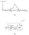
- a histogram of the disparity maps 321 of the previous frame is determined, as shown in FIG. 8 .
- a thresholding is performed to determine the minimum and maximum disparities in the scene. The thresholding may provide robustness against noise, since a disparity value is determined to be existent or correct if the frequency of that disparity value is higher than a predetermined threshold, e.g. a predetermined ration of the image size (%N). Examples of the threshold may be 1%, 2%, 5%, 8%, 10%, 15%, 20%, or other suitable percentage of the image size.
- the frequency of a disparity value represents the number of image elements having that disparity value.
- a maximum disparity value "disp_max” and a minimum disparity value "disp_min” are determined to define the disparity range of the previous stereo frame.
- the disparity range detection is performed on the previous disparity map 321 of the previous frame due to hardware constraints, such as timing. In other embodiments, if the hardware performance allows, the disparity range detection at block 370 may also be performed on the amended disparity maps 361 of the current image frame.
- the disparity range detected in block 370 is utilized to remove outliers in the amended disparity maps 361 output from the occlusion handling block 360.
- the extracted disparity values out of the detected disparity range are assigned as the bounds of the disparity range. For example, if a disparity value for an image element in the amended disparity maps 361 is smaller than the minimum disparity value, the disparity value of the image element is amended to be the minimum disparity value. Similarly, if a disparity value for an image element in the amended disparity maps 361 is larger than the maximum disparity value, the disparity value of the image element is amended to be the maximum disparity value.
- the disparity maps after the disparity range filter 380 is further amended in consideration of disparity maps of the previous frame, so as to determine final disparity maps 391.
- the final disparity value of the image element may be determined based on the amended disparity value of said image element, the disparity value and intensity value of the corresponding image element in the preceding image frame having the same position as said image element in the current image frame. This embodiment is preformed at a temporal filter 390, in which the range filtered disparity maps are further filtered in the temporal domain in order to remove possible flickers.
- the temporal filter may be performed in accordance with the following equation, based on the disparity maps of the previous frame and the temporal permeability weights determined in equation (7).
- D t x ⁇ y 1 - ⁇ Temp x ⁇ y .
- D t - 1 x ⁇ y wherein D t ( x , y ) and D t -1 ( x , y ) represent the disparity values of the pixels (x, y) in the current frame disparity map and in the previous frame disparity map, respectively.
- the temporal filter 390 makes colour-wise non-alternating pixels (whose temporal weight is high) in the current frame to be consistent with the previous frame in terms of the disparity values.
- the colour-wise altering pixels (whose temporal weight is low) in the current frame are not constrained to be consistent with the previous frame in terms of the disparity values.
- Embodiments above provide a method for determining disparity values for stereo image/video, which utilizes information of preceding rows and information of preceding image to achieve a more precise disparity determination.
- the embodiments determine disparity values by exploiting horizontal and vertical information transfer.
- Embodiments further provide a disparity determination method based on local optimization through a fast and efficient local cost aggregation over horizontal support area for each pixel.
- the support calculation strategy depends on the information permeability characteristics of pixels in the spatial and temporal directions based on the intensity similarities with the neighbouring pixels.
- the permeability weights enable the information to pass through smooth/texture-less regions, while preventing information passing from edge pixels.
- a plurality of spatial permeability weights and temporal permeability weight are determined, followed by pixel-wise cost calculation depending on RGB differences between the pixels in left and right views, deviation from the previously estimated upper row disparity assignments and the deviation from the disparity map of the previous frame.
- Pixel-wise cost values may be aggregated by a two-pass weighted integration strategy in horizontal direction. By utilizing the permeability weights for the corresponding direction, horizontal weighted summation is achieved in right and left scan order. This approach provides support area for each pixel depending on the texture characteristics with a low computational complexity.
- the cost value determination, amendment and aggregation are performed for each disparity candidate, and the disparity candidate which achieves the minimum supported cost is assigned to the corresponding image element.
- the vertically constrained cost values corresponding to disparities are supported in a wide range involving the pixels in the same row and the upper rows. This may increase the smoothness and robustness of the estimated disparity maps.
- a row-wise processing is performed in scan order, wherein the process of the next row starts when the current row disparity assignment is finalized.
- a left-right consistency check is performed to detect the reliable and occluded regions.
- the occlusion handling is achieved by a similar weighted filtering over reliable disparity estimates.
- bias is given for the pixels having large depth assignments, since most of the occluded regions are the background pixels around depth discontinuities.
- Temporal filtering with the disparity map of the previous frame may finalize the disparity estimation algorithm, which provides two disparity maps for left and right views modelling the 3D structure of the scene and enabling depth adjustment and depth based image enhancement for 3D Televisions on stereo contents.
- the temporal filtering enables temporally consistent and flicker-free disparity maps.
- the method of various embodiments may also be extended to 3D model extraction from views captured through multiple cameras.
- FIG. 9 shows an imaging system according to an embodiment.
- the imaging system 900 receive images 901, which may be a stereo image pair or a stereo video as described in FIGS. 2 and 3 above.
- the imaging system 900 includes an image processing device 910 for determining a disparity value for each image element in a first image with respect to a second image.
- the image processing device 910 may generate a disparity map 911, which may be disparity maps 231, 233, 341, 361, 391 determined in accordance with various embodiments described with regard to Figs. 2 and 3 above.
- An image render 930 may receive the image 901 and the determined disparity map 911 and render the image 901 for 3D display.
- the imaging system 900 may be embodied in a 3D TV or a computer, for example.
Landscapes
- Engineering & Computer Science (AREA)
- Computer Vision & Pattern Recognition (AREA)
- Physics & Mathematics (AREA)
- General Physics & Mathematics (AREA)
- Theoretical Computer Science (AREA)
- Image Processing (AREA)
- Image Analysis (AREA)
Abstract
Description
- Various embodiments relate generally to image processing. Furthermore, various embodiments relate to a method and an image processing device for determining disparity.
- With the development and success of three-dimensional (3D) technologies, its application is not limited to 3D movies in theatres, but is extending to home electronics, such as 3D TVs and other 3D consumer products. 3D vision or stereoscopic vision may be created by presenting two slightly different sets of images to a viewer, wherein one set includes left eye images corresponding to a left eye viewpoint and the other set includes right eye images corresponding to a right eye viewpoint. 3D displays (e.g., CRT, LCD, Plasma, etc.) show left eye and right eye views on the same surface, and by temporal or spatial multiplexing, make the left eye of a viewer only see the left eye view and the right eye only see the right-eye view. Disparities between the two views provide a vision with depth perception to the viewer, and make the viewer perceive a stereoscopic view.
- Disparity map estimation which provides information about the 3D position of objects or pixels in the stereo (multi-view) content becomes essential in stereo (multi-view) image processing. In literature, there are various methods providing disparity maps from 3D content involving stereo or multi-view video. Computational complexity is one of the fundamental constraints that restrict the utilization of several optimization techniques enabling high quality estimates, and accordingly local methods have been popular in recent years which do not require time consuming global optimization methods. Among many alternatives, dynamic programming based approaches provide a fast solution and can also be implemented in hardware.
- L. Wang et al. (High-quality real-time stereo using adaptive cost aggregation and dynamic programming, International Symposium on 3D Data Processing Visualization and Transmission, 2006) discloses a method exploiting scan-line optimization, in which each row is processed independently and the global energy is minimized. For each disparity candidate, all pixels in the left view are shifted to the right view (or vice-versa), and pixel-wise cost function is calculated by sum of absolute difference of Red, Green and Blue intensity values. These cost values are horizontally aggregated with additional smoothness constraints and ordering constraints. The smoothness rule makes pixels have similar disparity assignments as long as their cost functions have similar characteristics. The ordering rule forces the consecutive disparity assignments to be non-decreasing with a penalty function so that occlusion is set to a minimum level.
- Various embodiments determine or estimate a disparity map for stereo image or video at a higher precision and lower computational complexity than the conventional approaches.
- Various embodiments provide a method for determining a disparity value, an image processing device and an imaging device.
- Various embodiments provide a method for determining a disparity value for an image element in a row of a first image with respect to a second image. The method may include determining, for each disparity candidate of a plurality of disparity candidates, a cost value based on an intensity difference between the image element in the first image and a corresponding image element in the second image determined using the respective disparity candidate; determining, for each disparity candidate of the plurality of disparity candidates, an amended cost value based on the cost value of the image element and at least one of a first term and a second term, said first term being based on disparity values of one or more image elements from one or more preceding rows in the first image, and said second term being based on a disparity value of a corresponding image element in a preceding first image having the same position as the image element in the first image; and determining a disparity candidate out of the plurality of disparity candidates as the disparity value of the image element in the first image based on the amended cost values of the plurality of disparity candidates.
- In the drawings, like reference characters generally refer to the same parts throughout the different views. The drawings are not necessarily to scale, emphasis instead generally being placed upon illustrating the principles of the invention. In the following description, various embodiments are described with reference to the following drawings, in which:
-
Fig. 1 shows a schematic diagram of an image processing device according to an embodiment. -
Fig. 2 shows a flow diagram according to various embodiments. -
Fig. 3 shows a flow diagram according to various embodiments. -
Fig. 4 shows permeability weights determined for an image element according to an embodiment. -
Fig. 5 illustrates the aggregation of amended cost values according to an embodiment. -
Fig. 6 illustrates permeability weight distribution according to an embodiment. -
Fig. 7 shows a reliability mapping function according to an embodiment. -
Fig. 8 shows a histogram of a disparity map according to an embodiment. -
Fig. 9 shows an imaging system according to an embodiment. - Various embodiments provide a method and a device for determining disparity values, taking information of preceding pixels in the same image and information of pixels in the preceding image into consideration. Embodiments provide more accurate disparity estimation at low computational complexity.
- Various embodiments are directed to a method for determining a disparity value for an image element in a row of a first image with respect to a second image. The method may include determining, for each disparity candidate of a plurality of disparity candidates, a cost value based on an intensity difference between the image element in the first image and a corresponding image element in the second image determined using the respective disparity candidate; determining, for each disparity candidate of the plurality of disparity candidates, an amended cost value based on the cost value of the image element and at least one of a first term and a second term, said first term being based on disparity values of one or more image elements from one or more preceding rows in the first image, and said second term being based on a disparity value of a corresponding image element in a preceding first image having the same position as the image element in the first image; and determining a disparity candidate out of the plurality of disparity candidates as the disparity value of the image element in the first image based on the amended cost values of the plurality of disparity candidates.
- The first image may be a left eye view image, e.g. captured by a camera at the left eye position. The second image may be a right eye view image, e.g. captured by a camera at the right eye position. The first image and the second image may form a stereo image pair.
- In one embodiment, the image element described in the context of this description may include a picture element, also referred to as a pixel. In another embodiment, the image element described in the context of this description may include a plurality of picture elements, such as a block of picture elements or any object including a plurality of picture elements. The cost value, the amended cost value, the disparity value, the first term and the second term may be determined for each pixel or each block of pixels accordingly.
- According to an embodiment, the method may further include for each disparity candidate of the image element, determining the first term based on first disparity differences between the disparity candidate and the disparity values of the one or more image elements from the one or more preceding rows in the first image.
- In an embodiment, a first weighting factor corresponding to each of the one or more image elements from the one or more preceding rows is determined based on the intensity value of the respective one or more image elements. A sum of the first disparity differences weighted by the respective first weighting factor may be determined as the first term.
- In another embodiment, the method may further include for each disparity candidate of the image element, determining the second term based on a second disparity difference between the disparity candidate and the disparity value of the corresponding image element in the preceding first image.
- In an embodiment, a second weighting factor corresponding to the corresponding image element in the preceding first image is determined based on the intensity value of the corresponding image element. The second disparity difference weighted by the second weighting factor may be determined as the second term.
- According to a further embodiment, the method may further include, for each disparity candidate of the image element, determining an aggregated cost value by aggregating amended cost values determined for all image elements in the same row as said image element in the first image. The disparity candidate having the minimum aggregated cost value may be determined as the disparity value of the image element in the first image.
- In an embodiment, a weighted sum of the amended cost values determined for all image elements in the same row is determined as the aggregated cost value for the image element in the first image, wherein each amended cost value is weighted based on the intensity value of the respective image element which said amended cost value corresponds to.
- In a further embodiment, the method may include determining whether the disparity value of the image element in the first image is reliable based on a predetermined threshold and a disparity value of the corresponding image element in the second image, wherein the corresponding image element is determined using the disparity value of the image element in the first image.
- In an embodiment, an amended disparity value is determined for the image element in the first image, based on disparity values of all image elements in the same row as said image element, reliability of said all image elements, and intensity values of said all image elements. In a further embodiment, a disparity histogram of the preceding first image is determined which includes, for each disparity value of a plurality of disparity values determined for image elements of the preceding first image, a frequency value indicating the number of image elements having the respective disparity value. A maximum disparity value and a minimum disparity value may be determined based on the disparity histogram, wherein the maximum disparity value and the minimum disparity value define a range of disparity values having frequency values higher than a predetermined threshold. If the amended disparity value is smaller than the minimum disparity value, the amended disparity value of the image element in the first image may be determined to be the minimum disparity value. If the amended disparity value is larger than the maximum disparity value, the amended disparity value of the image element in the first image may be determined to be the maximum disparity value.
- In a further embodiment, a final disparity value of the image element in the first image may be determined based on the amended disparity value of said image element, the disparity value and intensity value of the corresponding image element in the preceding first image having the same position as said image element in the first image.
- The first image and the second image may be grayscale images in an embodiment. In another embodiment, the first image and the second image may be colour images. The above embodiment described in relation to the intensity value is analogously valid for the RGB (red, green, blue) values of colour images. Similarly, the colour images may be represented using other colour models, such as CMYK (cyan, magenta, yellow and key) and the various embodiments may be applied accordingly.
- Another embodiment is directed to an image processing device for determining a disparity value for an image element in a row of a first image with respect to a second image. The image processing device may include a cost value determination circuit configured to determine, for each disparity candidate of a plurality of disparity candidates, a cost value based on an intensity difference between the image element in the first image and a corresponding image element in the second image determined using the respective disparity candidate. The image processing device may include an amended cost value determination circuit configured to determine, for each disparity candidate of the plurality of disparity candidates, an amended cost value based on the cost value of the image element and at least one of a first term and a second term. The first term is based on disparity values of one or more image elements from one or more preceding rows in the first image, and the second term is based on a disparity value of a corresponding image element in a preceding first image having the same position as the image element in the first image. The image processing device may further include a disparity determination circuit configured to determine a disparity candidate out of the plurality of disparity candidates as the disparity value of the image element in the first image, based on the amended cost values of the plurality of disparity candidates.
- Embodiments described above in the context of the method for determining a disparity value for an image element are analogously valid for the image processing device, and vice versa. The various circuits, such as the cost value determination circuit, the amended cost value determination circuit, and the disparity determination circuit may each be configured to carry out the functions described in the method of various embodiments above.
- In an embodiment, the various "circuit" comprised in the image processing device may be understood as any kind of a logic implementing entity, which may be special purpose circuitry or a processor executing software stored in a memory, firmware, or any combination thereof. Thus, in an embodiment, a "circuit" may be a hard-wired logic circuit or a programmable logic circuit such as a programmable processor, e.g. a microprocessor (e.g. a Complex Instruction Set Computer (CISC) processor or a Reduced Instruction Set Computer (RISC) processor). A "circuit" may also be a processor executing software, e.g. any kind of computer program, e.g. a computer program using a virtual machine code such as e.g. Java. Any other kind of implementation of the respective functions described in the embodiments in this description may also be understood as a "circuit" in accordance with an alternative embodiment.
- In an embodiment, the image processing device may be a circuit described above configured to perform the method for determining the disparity value for the image element of the first image with respect to the second image.
- In another embodiment, a computer readable medium having a program stored thereon may be provided, wherein the program is to make a computer execute a method described in the above embodiments. The computer readable medium may include any data storage device, such as read-only memory (ROM), random-access memory (RAM), CD-ROMs, magnetic tapes, floppy disks and optical data storage devices.
- A further embodiment is directed to an imaging system. The imaging system may include an image processing device for determining a disparity value for each image element in a first image with respect to a second image in accordance with the above embodiments; and an image render for rendering the first image and the second image dependent on the determined disparity values.
- In an embodiment, the imaging system may further include a 3D content creator configured to generate 3D images or 3D video. Examples of the 3D content creator may include two cameras configured to capture images or video from different perspective, a stereo camera, and a 3D camcorder.
- In a further embodiment, the imaging system may include an encoder and/or a decoder configured to encode and decode the 3D content, respectively.
- In this context, the image processing device and the imaging system as described in this description may each include a memory which is for example used in the processing carried out by the image processing device and the imaging system. A memory used in the embodiments may be a volatile memory, for example a DRAM (Dynamic Random Access Memory), or a non-volatile memory, for example a PROM (Programmable Read Only Memory), an EPROM (Erasable PROM), EEPROM (Electrically Erasable PROM), or a flash memory, e.g., a floating gate memory, a charge trapping memory, an MRAM (Magneto resistive Random Access Memory) or a PCRAM (Phase Change Random Access Memory).
FIG. 1 shows a schematic diagram of an image processing device according to various embodiments. - The
image processing device 100 may be implemented by a computer system. In various embodiments, the cost value determination circuit, the amended cost value determination circuit, and the disparity determination circuit may also be implemented as modules executing on one or more computer systems. The computer system may include a CPU 101 (central processing unit), aprocessor 103, amemory 105, anetwork interface 107, input interface/devices 109 and output interface/devices 111. All thecomponents computer system 100 are connected and communicating with each other through acomputer bus 113. - The
memory 105 may be used as for storing images, cost values corresponding to the disparity candidates; amended cost values corresponding to the disparity candidates; and disparity values for the images determined according to the method of the embodiments. Thememory 105 may include more than one memory, such as RAM, ROM, EPROM, hard disk, etc. wherein some of the memories are used for storing data and programs and other memories are used as working memories. - In an embodiment, the
memory 105 may be configured to store instructions for determining disparity values for image elements in a first image with respect to a second image according to various embodiments. The instructions, when executed by theCPU 101, may cause theCPU 101 to determine determining a cost value for each disparity candidate based on an intensity difference between the image element in the first image and a corresponding image element in the second image determined using the respective disparity candidate, determine an amended cost value for each disparity candidate based on the cost value and at least one of a first term and a second term, and determine a disparity value for the image element based on the amended cost values of the disparity candidates. The instruction may also cause theCPU 101 to store the cost values, the amended cost values and the disparity values determined according to the method of the embodiments in thememory 105. - In various embodiments, the images may be taken by means of a camera, e.g. a video camera, e.g. a 3D video camera. Alteratively, the images may be received, e.g. via a computer network (e.g. the Internet) or via another Wide Area Network (WAN).
- In another embodiment, the
processor 103 may be a special purpose processor, in this example, an image processor, for executing the instructions described above. - The
CPU 101 or theprocessor 103 may be used as the image processing device as described in various embodiments below, and may be connected to an internal network (e.g. a local area network (LAN) or a wide area network (WAN) within an organization) and/or an external network (e.g. the Internet) through thenetwork interface 107. - The
Input 109 may include a keyboard, a mouse, etc. Theoutput 111 may include a display for display the images processed in the embodiments below. -
FIG. 2 shows a flow diagram according to various embodiments. - In the method of various embodiments, the disparity values of a first image with respect to a second image may be estimated or determined based on stereoscopic correspondence, in which a correspondence search may be performed to find a second image element in the second image corresponding to a first image element in the first image using a matching block or window surrounding the image elements. The similarity between the image elements may be measured by a cost function calculated, e.g., based on sum of squared difference, sum of absolute difference or normalized correlation, etc. The image element in the second image which gives the minimum value of the cost function indicates a best match with the first image element in the first image and may be determined to be the corresponding second image element. Accordingly, the disparity between these corresponding image elements may be determined as the disparity for the first image element of the first image.
- According to various embodiments, disparity values may be determined for an image pair including a first (digital or digitized) image corresponding to a
left view image 201 and a second (digital or digitized) image corresponding to aright view image 203, in which case the image pair may be referred to as a stereo image pair. Theimages images images - Based on the information provided in the
left view image 201 and theright view image 203, the cost values for each disparity candidate of a plurality of disparity candidates are determined for each image element at 210. For an image element in a row of theleft view image 201, a cost value for each disparity candidate is determined based on an intensity difference between the image element in theleft image 201 and a corresponding image element in theright image 203 determined using the respective disparity candidate. The position of the corresponding image element in theright image 203 is determined by the position of the image element in theleft image 201 shifted by the respective disparity candidate. - For each disparity candidate of the image element in the
left image 201, an amended cost value is determined at 220 based on the cost value determined at 210, and at least one of a first term and a second term. - The first term is based on disparity values of one or more image elements from one or more preceding rows in the same
left image 201. In an embodiment, theleft image 201 is processed in scan order, such that the disparity values are finalized for the current row before starting the disparity determination for the next row. In one example, if the scan order is from top to bottom, the preceding rows are the rows above the current row. If the scan order is from bottom to top, the preceding rows are the rows below the current row. The finalized disparity values of the image elements from the preceding rows in the sameleft image 201 are used to determine the first term, the preceding rows may include the immediately adjacent row and/or the rows further away than the immediately adjacent row. - In an embodiment, the first term may be based on first disparity differences between the disparity candidate and the disparity values of the one or more image elements from the one or more preceding rows in the
left image 201. In this manner, vertical information, i.e. disparity information of image elements in vertical direction is taken into consideration in amending the cost values. According to an embodiment, a first weighting factor corresponding to each of the one or more image elements from the one or more preceding rows is determined based on the intensity value of the respective one or more image elements. The first weighting factor may also be referred to as permeability weights, and will be described in more detail with reference toFig. 3 below. The first term may be determined to be a sum of the first disparity differences weighted by the respective first weighting factors. The second term may be based on a disparity value of a corresponding image element in a preceding left image having the same position as the image element in theleft image 201. The preceding left image is a left image frame preceding the currentleft image frame 201 in the video. The information of preceding images 221, such as intensity values and disparity values of preceding images, may be provided to the amended costvalue determination block 220. - In an embodiment, the second term may be based on a second disparity difference between the disparity candidate and the disparity value of the corresponding image element in the preceding left image. In this manner, temporal information, i.e. disparity information of image elements in a previous image frame is taken into consideration in amending the cost values. According to an embodiment, a second weighting factor corresponding to the corresponding image element in the preceding left image is determined based on the intensity value of the corresponding image element. The second weighting factor may also be referred to as permeability weights, and will be described in more detail with reference to
Fig. 3 below. The second term may be determined to be the second disparity difference weighted by the second weighting factor. - Upon determining the amended cost values for the plurality of disparity candidates, a disparity candidate out of the plurality of disparity candidates may be determined as the disparity value for the image element in the
left image 201 at 230 based on the amended cost values. In an embodiment, a disparity candidate having the minimum amended cost value is determined as the disparity value for the image element. - In one embodiment, the amended cost values for the image element may be further amended by aggregating amended cost values determined for all image elements in the same row as said image element. In an embodiment, the aggregated cost value for each disparity candidate is determined to be a weighted sum of the amended cost values for all image elements in the same row, wherein each amended cost value is weighted based on the intensity value of the respective image element which said amended cost value corresponds to. The weights used for weighting the amended cost values may also be referred to as permeability weights, and will be described in more detail with reference to
Fig. 3 below. According to an embodiment, a disparity candidate having the minimum aggregated cost value is determined out of the plurality of disparity candidates as the disparity value for the image element in theleft image 201 at 230. - The cost value determination at 210, the amended cost value determination at 220, and the disparity determination at 230 may be performed for all the image elements in the
left view image 201. Accordingly, aleft disparity map 231 may be determined including disparity values for all image elements in theleft view image 201 with respect to theright view image 203. The operations described in the above embodiments are performed for image elements in theleft image 201 with respect to theright image 203, and may be similarly performed for all elements in theright image 203 with respect to theleft image 201 to obtain aright disparity map 233. - The
left disparity map 231 and theright disparity map 233 may be used, e.g. by an image render, together with theimages - The image element described in the various embodiments in the description may be a pixel. In another embodiment, the image element may include a plurality of pixels, such as a block of picture elements or any object including a plurality of picture elements. The cost value, the amended cost value, the weighting factors, and the disparity value may be determined for each pixel (in other words, pixel-wise) or each block (in other words, block-wise) of pixels accordingly.
- In determining the disparity values for an image, the embodiments as described above take the information of preceding rows in the same image and the information of the preceding image into consideration, which determines the disparity values with increased accuracy. In addition, by determining the minimum cost value for disparity candidates, it is not necessary to store all cost values for all disparity candidates. Instead, the cost values may be updated successively for each disparity candidate, and the disparity map is only updated in case a respective cost value for a pixel and a disparity candidate is lower than the cost value of the same pixel for the previous disparity candidates.
- The
left disparity map 231 and theright disparity map 233 may be further processed, for example, to detect occluded regions within the images, amend disparity values of the occluded regions, and remove noise and errors, etc. as will be further described with reference toFig. 3 below. -
FIG. 3 shows a flow diagram according to various embodiments. - In
Fig. 3 , disparity maps for image elements in aleft image 301 and aright image 303 of the nth frames of a sequence of frames are determined. In this embodiment, the image element is a pixel. In an embodiment, the disparity map determination may be performed in a down-sampled domain, e.g. the width and height of the down-sampled image may be a decreased version of the original image size by a factor of 4. In this embodiment, the disparity determination is performed in the top-to-bottom scan order, such that the disparity values are finalized for the current row before proceeding to determine the disparity values for the next row. In this manner, finalized disparity values of the preceding rows may be utilized in determining the cost values of the current row to provide smoothness. - The
permeability calculation block 305 is provided to calculate permeability weights for image elements in theleft image 301 and theright image 303. In various embodiments, the permeability weights for an image element may be determined in six directions including five spatial directions and one temporal direction. The permeability weights may be determined in less than or more than six directions in other embodiments. The permeability weights represents the ration of information that passes through the image element in the corresponding direction. -
FIG. 4 shows the permeability weights determined for animage element 300 according to an embodiment. The permeability weights are measured by comparing the intensity values of thecentre image element 300 with six neighbours. The intensity similarity of thecentre image element 300 with the neighbouring image elements determines the permeability of information through theimage element 300 in the corresponding direction. - In an embodiment, the
images images images image element 300 and the neighbouring image elements in accordance with the following equation:
- In an embodiment, the permeability weights of an image element (x, y) in six directions as shown in
Fig. 4 may be determined according to the following equations:


wherein µ Left (x,y), µ right (x,y), µ Up-Left (x,y), µ Up (x,y), µ Up-Right (x,y) represent the permeability weights of theimage element 300 in the left, right, up-left, up and up-right directions, respectively, and may be referred to as spatial permeability weights. µ Temp (x,y) represents the permeability weights of theimage element 300 in the temporal direction considering the intensity change between the previous image frame t-1 and the current image frame t, and may be referred to as a temporal permeability weight. IRCB (x,y) represents the Red colour value, the Green colour value or the Blue colour value of the image element (x, y), respectively. e represents the exponential function. - In accordance with the above embodiments, a larger intensity difference between the
image element 300 and an image element in the corresponding direction would produce a smaller permeability weight in the corresponding direction, indicating less information passing through theimage element 300 into the corresponding direction. In the above embodiment, exponential function is used in determining the permeability weights. In another embodiment, other monotonically decreasing functions which provide output values between 0 and 1 may be used to determine the permeability weights. Furthermore, in alternative embodiments, the permeability weights of an image element may be determined taking into account image elements which are located further away from the image element the permeability weights are determined for; by way of example, one or more pixels may be arranged (which may be ignored or which may also be taken into account) between the image element the permeability weights are determined for and the respective permeability weight image element. Furthermore, in case the scanning direction is different, e.g. the inverse direction to the direction as described above, permeability weights of theimage element 300 may be determined in the left, right, down-left, down and down-right directions, respectively. - For each image element in the
images images permeability calculation block 305. - The cost values for each image element are determined for each disparity candidate at a pixel-wise
cost calculation block 310. In an embodiment, disparity assignment for a stereo image pair may be in horizontal direction only, and the search is conducted by shifting the pixel along the horizontal direction only. A fixed search range may be exploited. In an embodiment, the cost value for a disparity candidate is determined based on an intensity difference between the image element in theleft image 201 and a corresponding image element in theright image 203 determined using the corresponding disparity candidate. - In an embodiment wherein the
images 
wherein CostLeft (x,y,d) represent the cost value of the pixel (x, y) in the left image for a disparity candidate d, and CostRight (x,y,d) represents the cost value of the pixel (x, y) in the right image for a disparity candidate d. ILeft and IRight represents the RGB values in the left image and the right image. T represents the truncation of the cost values in order to reduce the effect of noise. - Since the cost values of the left image and the right image are related to each other, only one calculation for either left image or right image is needed and the cost values are copied for the other image.
- The cost values calculated in
block 310 correspond to the colour-wise similarity between the pixels in left andright images - According to an embodiment, the amended cost values are determined at 320 based on the cost value of the image element and at least one of a first term and a second term, wherein the first term is based on disparity values of one or more image elements from one or more preceding rows in the first image, and the second term is based on a disparity value of a corresponding image element in a preceding first image having the same position as the image element in the first image.
- In an embodiment, the amended disparity value for the image element (x, y) in the left image may be determined in accordance with the following equation:

wherein CLeft (x,y,d) represent the amended cost value of the pixel (x, y) in the left image for a disparity candidate d, and CostLeft (x,y,d) represents the cost value of the pixel (x, y) for the disparity candidate d determined according to equation (8). D(x-1,y-1) represents the finalized disparity value determined for the pixel (x-1, y-1) in an upper row of the same image. D t-1(x,y) represents the finalized disparity value determined for the pixel (x, y) in the previous left image t-1. - According to the above embodiments, a smoothness constraint is provided by weighting the difference between the disparity candidate value (d) and the determined disparity values of the previous row using permeability weights for the corresponding direction. Moreover, the disparity map of the previous frame (Dt-1) 321 is also constrained by the temporal variation of the pixel. According to the embodiment of equation (9), the disparity values of the preceding row and the previous frame in time are favoured as long as the colour variation of the pixel (x,y) is low in the corresponding directions.
- In the embodiment of equation (9), disparity values of three pixels in the immediately adjacent row in the up-left, up and up-right directions are taken into consideration when determining the amended cost value. It is understood that more or less than three pixels in the immediately adjacent row and/or pixels in one or more rows further away from the immediately adjacent row may be used to determine the amended cost value.
- In the embodiment of equation (9), both disparity values of the upper row (which correspond to the first term) and the disparity value of the previous frame (which corresponds to the second term) are used in determining the amended cost value. In other embodiment, only one of the two terms may be used to determine the amended cost value, so as to provide smoothness constraint in either vertical domain or temporal domain.
- The operations using vertical and temporal information at 320 above are also performed for the
right image 303. Throughblock 320, the general disparity distribution among the image is extracted by transferring information from all possible directions involving vertical and temporal relations. - Based on the amended cost values output from the
block 320, a disparity value for the image element may be determined. In an embodiment, the disparity candidate having the minimum amended cost values among the plurality of disparity candidates are determined at theminimization block 340 to be the disparity value for the image element. - In another embodiment, before determining the disparity value, the amended cost values may be further processed by a horizontal integration at a
horizontal aggregation block 330, which provides pixel-wise cost values to be supported in the horizontal direction using the permeability weights determined atblock 305. - The input to the
horizontal aggregation block 330 is the amended cost map output fromblock 320 and the permeability maps output fromblock 305, and the output is the aggregated cost map. - The horizontal aggregation at 330 is performed by weighted integration in the left and right scan order consecutively for each row independently.
FIG. 5 illustrates the aggregation of amended cost values according to an embodiment. As illustrated inFig. 5 , amended pixel-wise cost values are summed towards left and right directions using the permeability weights in left and right directions, respectively, resulting in two different aggregated costs (AC) for each pixel from opposite directions. - In an embodiment, the aggregated costs from left and right directions are determined in accordance with the following equation:

wherein ACLeft (x,y,d) represents the aggregated cost value from the left of the image element (x,y), and ACRight (x,y,d) represents the aggregated cost value from the right of the image element (x,y). ACH (x,y,d) represents the final aggregated cost value for the image element (x,y). - According to the above embodiment, the information from the left direction is carried out through permeability of pixels into the right direction, and vice-versa for the right direction. The two aggregated cost values from both directions are summed up to obtain the final horizontal aggregation value. During the weighted integration, permeability weights enables information to penetrate through smooth surfaces, while prevents information passing from edge regions. This would allow object boundaries to be preserved during the support calculation of the cost values. As a result of the horizontal integration, depending on the texture characteristics among the corresponding row, a weighted summation among the entire row (corresponding to horizontal window of image width) is obtained for each pixel with constant computation complexity, i.e. two multiplications and three additions for one pixel.
- According to the above embodiment, the information from pixels further away from the current pixel penetrates by the consecutive multiplications of the permeability values.
FIG. 6 illustrates the permeability weight distribution according to an embodiment. As shown inFig. 6 , dark pixels indicate permeability weights close to "0", and bright pixels indicate permeability weights close to "1". The penetration approach provides connected support areas for each pixel, wherein the effective permeability weights decrease as the distance to the corresponding pixel increases. - In accordance with the above embodiments, the aggregated cost value for each disparity candidate is determined at 330. The cost value determination at
block 310, the amended cost value determination atblock 320 and the aggregation of the amended cost values atblock 330 are preformed for each disparity candidate of the image element. Atminimization block 340, the disparity candidate having the minimum aggregated cost is determined and is assigned to the corresponding pixel. The aggregation is performed for amended cost maps of both views, and the disparity maps 341 for both views are determined. - In a further embodiment, the disparity maps 341 determined for left and right images independently above may be further processed as described above.
- Emerging from the same 3D scene, the disparity maps for left view and right view should be consistent with each other. In an embodiment, a consistency cross-check is performed at
block 350 to detect reliable disparity assignments. Each pixel in the left disparity map may be shifted by the assigned disparity value to the right disparity map, and the corresponding disparity value in the right disparity map is compared with the assigned disparity value in the left disparity map. If the difference between the disparity values is below a predetermined threshold, corresponding pixel in the left view is marked as reliable. If the difference is above the predetermined threshold, the pixel is marked as unreliable. - In an embodiment, the reliability detection for a pixel (x, y) in the left disparity map is performed in accordance with the following equation:

wherein DLeft (x,y) represents the determined disparity value of the pixel (x, y) in the left disparity map, DRight (x+DLeft (x,y),y) represents the determined disparity value of the shifted pixel (x+DLeft (x,y),y) in the right disparity map. Left_Reliability(x,y) represents the reliability of the pixel (x, y) in the left view. - The reliability detection is repeated for the right disparity map to determine the reliability of pixels in the right view. The output of the
cross-check block 350 includes two reliability maps assigning "1" for reliable pixels and "0" for the unreliable pixels. - In a further embodiment, occluded regions and detected unreliable disparity assignments are processed at an
occlusion handling block 360. Occluded pixels are normally located among the depth discontinuities where object boundaries exist. The foreground objects have larger disparities, and thus occluding the background where the depth is larger. As a result, it may be concluded that occluded regions belong to the local background around the depth discontinuities. According to an embodiment, the missing disparity assignments of the occluded regions may be copied through the background. The characteristics of the occluded regions may also be taken into consideration in the occlusion handling at 360. In that manner, the proposed method atblock 360 gives bias to the large depth assignments and performs a support strategy similar to the cost aggregation atblock 330 above. In an embodiment, the disparity assignments of the occluded regions are performed by weighted averaging over reliable pixels based on depth ordering and intensity similarity. - In an embodiment, a linear function with the range of (0, 1) is applied to the un-occluded pixels, which assigns "1" for pixels having the highest depth assignments, "0" for pixels having the lowest depth assignments and a value between "0" and "1" for the remaining pixels. The characteristic of the reliability mapping function is illustrated in
FIG. 7 . This mapping function favours higher depth values, since the occluded regions belong to the local backgrounds in all cases. As a result, two maps for stereo pairs are obtained indicating reliability values, such that unreliable pixels are assigned to "0", and values between (0, 1) are assigned to the reliable pixels depending on the initial disparity values. - At
occlusion handling block 360, the disparity values are scaled by the reliability values in accordance with equation (12) below, in order to prevent information of occluded (unreliable) regions, decrease the effect of foreground regions for occlusion handling and give more importance to reliable background regions which are the strongest supports for occlusions. - In an embodiment, a horizontal aggregation is performed on the scaled disparity values similar to the horizontal aggregation of cost values at 330. The aggregation may be performed by determining a weighted summation of the scaled disparity values weighted by the permeability weights. An embodiment of the aggregation is performed in accordance with equation (13) below. In order to determine the proper disparity assignment for the occluded pixel, the weighted summation may be normalized by the summation of the reliability weights, which can be obtained by aggregation over reliability values. Accordingly, the reliability maps are also aggregated in the horizontal direction. The weighted summation of data composed of reliability values result in a total weight that are utilized during weighted summation of the depth data for each pixel. Two maps are obtained, wherein the weighted sum of disparity values and the total weight are stored. Hence, the amended disparity values may be achieved by a normalization step as in equation (13), wherein the background disparity assignments are favoured to fill the occluded region.


wherein

- In accordance with the embodiment of equation (13), the normalization step is performed through dividing the weighted disparity sums by sum of weights. As a result, the occluded regions are filled by filtering disparity assignments of reliable regions, wherein background pixels (the depth of which is larger) are favoured during filtering. This operation is performed for both left and right images independently and the amended disparity maps 361 are obtained.
- Due to large occluded regions, noise and reflection caused by lightening conditions, the amended disparity maps 361 may include erroneous disparity values. For example, disparity values which are out of the range of the actual (true) 3D scene may be included in the amended disparity maps 361. According to an embodiment, a disparity range detection is performed at
block 370 and a disparity range filtering is performed atblock 380 to remove outlier disparity values which are most probably out of the disparity range. - In
block 370, final disparity maps 321 of left and right views (for the previous frame) are input for detecting the disparity range, which will be exploited in the current frame in absence of scene change. According to an embodiment, a histogram of the disparity maps 321 of the previous frame is determined, as shown inFIG. 8 . A thresholding is performed to determine the minimum and maximum disparities in the scene. The thresholding may provide robustness against noise, since a disparity value is determined to be existent or correct if the frequency of that disparity value is higher than a predetermined threshold, e.g. a predetermined ration of the image size (%N). Examples of the threshold may be 1%, 2%, 5%, 8%, 10%, 15%, 20%, or other suitable percentage of the image size. The frequency of a disparity value represents the number of image elements having that disparity value. Based on the predetermined threshold, a maximum disparity value "disp_max" and a minimum disparity value "disp_min" are determined to define the disparity range of the previous stereo frame. In this embodiment, the disparity range detection is performed on the previous disparity map 321 of the previous frame due to hardware constraints, such as timing. In other embodiments, if the hardware performance allows, the disparity range detection atblock 370 may also be performed on the amended disparity maps 361 of the current image frame. - At the disparity
range filter block 380, the disparity range detected inblock 370 is utilized to remove outliers in the amended disparity maps 361 output from theocclusion handling block 360. According to an embodiment, the extracted disparity values out of the detected disparity range are assigned as the bounds of the disparity range. For example, if a disparity value for an image element in the amended disparity maps 361 is smaller than the minimum disparity value, the disparity value of the image element is amended to be the minimum disparity value. Similarly, if a disparity value for an image element in the amended disparity maps 361 is larger than the maximum disparity value, the disparity value of the image element is amended to be the maximum disparity value. - In a further embodiment, the disparity maps after the
disparity range filter 380 is further amended in consideration of disparity maps of the previous frame, so as to determine final disparity maps 391. In an embodiment, the final disparity value of the image element may be determined based on the amended disparity value of said image element, the disparity value and intensity value of the corresponding image element in the preceding image frame having the same position as said image element in the current image frame. This embodiment is preformed at atemporal filter 390, in which the range filtered disparity maps are further filtered in the temporal domain in order to remove possible flickers. - In an embodiment, the temporal filter may be performed in accordance with the following equation, based on the disparity maps of the previous frame and the temporal permeability weights determined in equation (7).

wherein Dt (x,y) and D t-1(x,y) represent the disparity values of the pixels (x, y) in the current frame disparity map and in the previous frame disparity map, respectively. - The
temporal filter 390 makes colour-wise non-alternating pixels (whose temporal weight is high) in the current frame to be consistent with the previous frame in terms of the disparity values. The colour-wise altering pixels (whose temporal weight is low) in the current frame are not constrained to be consistent with the previous frame in terms of the disparity values. - Various embodiments above provide a method for determining disparity values for stereo image/video, which utilizes information of preceding rows and information of preceding image to achieve a more precise disparity determination. The embodiments determine disparity values by exploiting horizontal and vertical information transfer. Embodiments further provide a disparity determination method based on local optimization through a fast and efficient local cost aggregation over horizontal support area for each pixel. The support calculation strategy depends on the information permeability characteristics of pixels in the spatial and temporal directions based on the intensity similarities with the neighbouring pixels. The permeability weights enable the information to pass through smooth/texture-less regions, while preventing information passing from edge pixels. For each image element, a plurality of spatial permeability weights and temporal permeability weight are determined, followed by pixel-wise cost calculation depending on RGB differences between the pixels in left and right views, deviation from the previously estimated upper row disparity assignments and the deviation from the disparity map of the previous frame. Pixel-wise cost values may be aggregated by a two-pass weighted integration strategy in horizontal direction. By utilizing the permeability weights for the corresponding direction, horizontal weighted summation is achieved in right and left scan order. This approach provides support area for each pixel depending on the texture characteristics with a low computational complexity. The cost value determination, amendment and aggregation are performed for each disparity candidate, and the disparity candidate which achieves the minimum supported cost is assigned to the corresponding image element. The vertically constrained cost values corresponding to disparities are supported in a wide range involving the pixels in the same row and the upper rows. This may increase the smoothness and robustness of the estimated disparity maps. A row-wise processing is performed in scan order, wherein the process of the next row starts when the current row disparity assignment is finalized.
- In further embodiments, after the disparity assignment is determined for both views, a left-right consistency check is performed to detect the reliable and occluded regions. The occlusion handling is achieved by a similar weighted filtering over reliable disparity estimates. During the occlusion handling, bias is given for the pixels having large depth assignments, since most of the occluded regions are the background pixels around depth discontinuities. Temporal filtering with the disparity map of the previous frame may finalize the disparity estimation algorithm, which provides two disparity maps for left and right views modelling the 3D structure of the scene and enabling depth adjustment and depth based image enhancement for 3D Televisions on stereo contents. The temporal filtering enables temporally consistent and flicker-free disparity maps. The method of various embodiments may also be extended to 3D model extraction from views captured through multiple cameras.
FIG. 9 shows an imaging system according to an embodiment. - The
imaging system 900 receiveimages 901, which may be a stereo image pair or a stereo video as described inFIGS. 2 and3 above. - The
imaging system 900 includes animage processing device 910 for determining a disparity value for each image element in a first image with respect to a second image. Theimage processing device 910 may generate adisparity map 911, which may be disparity maps 231, 233, 341, 361, 391 determined in accordance with various embodiments described with regard toFigs. 2 and3 above. - An image render 930 may receive the
image 901 and thedetermined disparity map 911 and render theimage 901 for 3D display. - The
imaging system 900 may be embodied in a 3D TV or a computer, for example. - While the invention has been particularly shown and described with reference to specific embodiments, it should be understood by those skilled in the art that various changes in form and detail may be made therein without departing from the spirit and scope of the invention as defined by the appended claims. The scope of the invention is thus indicated by the appended claims and all changes which come within the meaning and range of equivalency of the claims are therefore intended to be embraced.
Claims (14)
- A method for determining a disparity value for an image element in a row of a first image with respect to a second image, the method comprising:- for each disparity candidate of a plurality of disparity candidates, determining a cost value based on an intensity difference between the image element in the first image and a corresponding image element in the second image determined using the respective disparity candidate;- for each disparity candidate of the plurality of disparity candidates, determining an amended cost value based on the cost value of the image element and at least one of a first term and a second term, said first term being based on disparity values of one or more image elements from one or more preceding rows in the first image, and said second term being based on a disparity value of a corresponding image element in a preceding first image having the same position as the image element in the first image; and- determining a disparity candidate out of the plurality of disparity candidates as the disparity value of the image element in the first image based on the amended cost values of the plurality of disparity candidates.
- The method of claim 1, further comprising:- for each disparity candidate of the image element, determining the first term based on first disparity differences between the disparity candidate and the disparity values of the one or more image elements from the one or more preceding rows in the first image.
- The method of claim 2, further comprising:- determining a first weighting factor corresponding to each of the one or more image elements from the one or more preceding rows based on the intensity value of the respective one or more image elements; and- determining a sum of the first disparity differences weighted by the respective first weighting factor as the first term.
- The method of any one of claims 1 to 3, further comprising:- for each disparity candidate of the image element, determining the second term based on a second disparity difference between the disparity candidate and the disparity value of the corresponding image element in the preceding first image.
- The method of claim 4, further comprising:- determining a second weighting factor corresponding to the corresponding image element in the preceding first image based on the intensity value of the corresponding image element; and- determining the second disparity difference weighted by the second weighting factor as the second term.
- The method of any one of claims 1 to 5, further comprising:- for each disparity candidate of the image element, determining an aggregated cost value by aggregating amended cost values determined for all image elements in the same row as said image element in the first image.
- The method of claim 6, further comprising:- determining the disparity candidate having the minimum aggregated cost value as the disparity value of the image element in the first image.
- The method of claim 6 or 7, wherein- determining the aggregated cost value for the image element in the first image comprises determining a weighted sum of the amended cost values determined for all image elements in the same row, each amended cost value being weighted based on the intensity value of the respective image element which said amended cost value corresponds to.
- The method of any of claims 1 to 8, further comprising:- determining whether the disparity value of the image element in the first image is reliable based on a predetermined threshold and a disparity value of the corresponding image element in the second image, said corresponding image element being determined using the disparity value of the image element in the first image.
- The method of claim 9, further comprising:- determining an amended disparity value for the image element in the first image based on disparity values of all image elements in the same row as said image element, reliability of said all image elements, and intensity values of said all image elements.
- The method of claim 10, further comprising:- determining a disparity histogram of the preceding first image, which includes, for each disparity value of a plurality of disparity values determined for image elements of the preceding first image, a frequency value indicating the number of image elements having the respective disparity value;- determining a maximum disparity value and a minimum disparity value based on the disparity histogram, said maximum disparity value and said minimum disparity value defining a range of disparity values having frequency values higher than a predetermined threshold; and- determining the amended disparity value of the image element in the first image to be the minimum disparity value if the amended disparity value is smaller than the minimum disparity value, and determining the amended disparity value of the image element in the first image to be the maximum disparity value if the amended disparity value is larger than the maximum disparity value.
- The method of claim 11, further comprising:- determining a final disparity value of the image element in the first image based on the amended disparity value of said image element, the disparity value and intensity value of the corresponding image element in the preceding first image having the same position as said image element in the first image.
- An image processing device for determining a disparity value for an image element in a row of a first image with respect to a second image, the device comprising:- a cost value determination circuit configured to determine, for each disparity candidate of a plurality of disparity candidates, a cost value based on an intensity difference between the image element in the first image and a corresponding image element in the second image determined using the respective disparity candidate;- an amended cost value determination circuit configured to determine, for each disparity candidate of the plurality of disparity candidates, an amended cost value based on the cost value of the image element and at least one of a first term and a second term, said first term being based on disparity values of one or more image elements from one or more preceding rows in the first image, and said second term being based on a disparity value of a corresponding image element in a preceding first image having the same position as the image element in the first image; and- a disparity determination circuit configured to determine a disparity candidate out of the plurality of disparity candidates as the disparity value of the image element in the first image based on the amended cost values of the plurality of disparity candidates.
- An imaging system, comprising:- an image processing device for determining a disparity value for each image element in a first image with respect to a second image in accordance with claim 13; and- an image render for rendering the first image and the second image dependent on the determined disparity values.
Priority Applications (2)
| Application Number | Priority Date | Filing Date | Title |
|---|---|---|---|
| EP12165311.7A EP2657909B1 (en) | 2012-04-24 | 2012-04-24 | Method and image processing device for determining disparity |
| TR2018/11588T TR201811588T4 (en) | 2012-04-24 | 2012-04-24 | A method and image processing device for determining non-discrimination. |
Applications Claiming Priority (1)
| Application Number | Priority Date | Filing Date | Title |
|---|---|---|---|
| EP12165311.7A EP2657909B1 (en) | 2012-04-24 | 2012-04-24 | Method and image processing device for determining disparity |
Publications (2)
| Publication Number | Publication Date |
|---|---|
| EP2657909A1 true EP2657909A1 (en) | 2013-10-30 |
| EP2657909B1 EP2657909B1 (en) | 2018-06-13 |
Family
ID=46044450
Family Applications (1)
| Application Number | Title | Priority Date | Filing Date |
|---|---|---|---|
| EP12165311.7A Active EP2657909B1 (en) | 2012-04-24 | 2012-04-24 | Method and image processing device for determining disparity |
Country Status (2)
| Country | Link |
|---|---|
| EP (1) | EP2657909B1 (en) |
| TR (1) | TR201811588T4 (en) |
Cited By (2)
| Publication number | Priority date | Publication date | Assignee | Title |
|---|---|---|---|---|
| KR20180019711A (en) * | 2015-07-03 | 2018-02-26 | 후아웨이 테크놀러지 컴퍼니 리미티드 | Image processing apparatus and method |
| CN109983468A (en) * | 2016-12-01 | 2019-07-05 | 深圳市大疆创新科技有限公司 | Use the method and system of characteristic point detection and tracking object |
Citations (2)
| Publication number | Priority date | Publication date | Assignee | Title |
|---|---|---|---|---|
| US20110110583A1 (en) * | 2008-06-24 | 2011-05-12 | Dong-Qing Zhang | System and method for depth extraction of images with motion compensation |
| US20110158528A1 (en) * | 2009-12-31 | 2011-06-30 | Sehoon Yea | Determining Disparity Search Range in Stereo Videos |
-
2012
- 2012-04-24 TR TR2018/11588T patent/TR201811588T4/en unknown
- 2012-04-24 EP EP12165311.7A patent/EP2657909B1/en active Active
Patent Citations (2)
| Publication number | Priority date | Publication date | Assignee | Title |
|---|---|---|---|---|
| US20110110583A1 (en) * | 2008-06-24 | 2011-05-12 | Dong-Qing Zhang | System and method for depth extraction of images with motion compensation |
| US20110158528A1 (en) * | 2009-12-31 | 2011-06-30 | Sehoon Yea | Determining Disparity Search Range in Stereo Videos |
Non-Patent Citations (3)
| Title |
|---|
| CIGLA C ET AL: "Edge-aware stereo matching with O(1) complexity", PROCEEDINGS OF THE SPIE - THE INTERNATIONAL SOCIETY FOR OPTICAL ENGINEERING SPIE - THE INTERNATIONAL SOCIETY FOR OPTICAL ENGINEERING USA, vol. 8290, 30 March 2012 (2012-03-30), XP002679564, ISSN: 0277-786X * |
| L. WANG ET AL., HIGH-QUALITY REAL-TIME STEREO USING ADAPTIVE COST AGGREGATION AND DYNAMIC PROGRAMMING, INTERNATIONAL SYMPOSIUM ON 3D DATA PROCESSING VISUALIZATION AND TRANSMISSION, 2006 |
| SANG-BEOM LEE ET AL: "View-consistent multi-view depth estimation for three-dimensional video generation", 3DTV-CONFERENCE: THE TRUE VISION - CAPTURE, TRANSMISSION AND DISPLAY OF 3D VIDEO (3DTV-CON), 2010, IEEE, PISCATAWAY, NJ, USA, 7 June 2010 (2010-06-07), pages 1 - 4, XP031706348, ISBN: 978-1-4244-6377-0 * |
Cited By (4)
| Publication number | Priority date | Publication date | Assignee | Title |
|---|---|---|---|---|
| KR20180019711A (en) * | 2015-07-03 | 2018-02-26 | 후아웨이 테크놀러지 컴퍼니 리미티드 | Image processing apparatus and method |
| JP2018521414A (en) * | 2015-07-03 | 2018-08-02 | ホアウェイ・テクノロジーズ・カンパニー・リミテッド | Image processing apparatus and image processing method |
| US10504234B2 (en) | 2015-07-03 | 2019-12-10 | Huawei Technologies Co., Ltd. | Image processing apparatus and method |
| CN109983468A (en) * | 2016-12-01 | 2019-07-05 | 深圳市大疆创新科技有限公司 | Use the method and system of characteristic point detection and tracking object |
Also Published As
| Publication number | Publication date |
|---|---|
| TR201811588T4 (en) | 2018-09-21 |
| EP2657909B1 (en) | 2018-06-13 |
Similar Documents
| Publication | Publication Date | Title |
|---|---|---|
| US9485495B2 (en) | Autofocus for stereo images | |
| CN101960860B (en) | System and method for depth map extraction using region-based filtering | |
| US9117295B2 (en) | Refinement of depth maps by fusion of multiple estimates | |
| EP2175663B1 (en) | Image processing apparatus | |
| US9445071B2 (en) | Method and apparatus generating multi-view images for three-dimensional display | |
| US20140009462A1 (en) | Systems and methods for improving overall quality of three-dimensional content by altering parallax budget or compensating for moving objects | |
| US20110032341A1 (en) | Method and system to transform stereo content | |
| EP3311361B1 (en) | Method and apparatus for determining a depth map for an image | |
| US8369609B2 (en) | Reduced-complexity disparity map estimation | |
| US9769460B1 (en) | Conversion of monoscopic visual content to stereoscopic 3D | |
| US20100289815A1 (en) | Method and image-processing device for hole filling | |
| EP2747427B1 (en) | Method, apparatus and computer program usable in synthesizing a stereoscopic image | |
| KR20170070148A (en) | Processing of disparity of a three dimensional image | |
| CN105791795A (en) | Three-dimensional image processing method and device and three-dimensional video display device | |
| EP2680224B1 (en) | Method and device for determining a depth image | |
| EP2466902B1 (en) | Information permeability based disparity estimation in stereo video | |
| EP2657909B1 (en) | Method and image processing device for determining disparity | |
| EP2557537B1 (en) | Method and image processing device for processing disparity | |
| US20140092222A1 (en) | Stereoscopic image processing device, stereoscopic image processing method, and recording medium | |
| US9787980B2 (en) | Auxiliary information map upsampling | |
| EP2677496B1 (en) | Method and device for determining a depth image | |
| US9008413B2 (en) | Processing method for a pair of stereo images | |
| Wei et al. | Iterative depth recovery for multi-view video synthesis from stereo videos | |
| US9137519B1 (en) | Generation of a stereo video from a mono video | |
| Bauza et al. | A multi-resolution multi-size-windows disparity estimation approach |
Legal Events
| Date | Code | Title | Description |
|---|---|---|---|
| PUAI | Public reference made under article 153(3) epc to a published international application that has entered the european phase |
Free format text: ORIGINAL CODE: 0009012 |
|
| AK | Designated contracting states |
Kind code of ref document: A1 Designated state(s): AL AT BE BG CH CY CZ DE DK EE ES FI FR GB GR HR HU IE IS IT LI LT LU LV MC MK MT NL NO PL PT RO RS SE SI SK SM TR |
|
| AX | Request for extension of the european patent |
Extension state: BA ME |
|
| 17P | Request for examination filed |
Effective date: 20140429 |
|
| 17Q | First examination report despatched |
Effective date: 20150108 |
|
| REG | Reference to a national code |
Ref country code: DE Ref legal event code: R079 Ref document number: 602012047357 Country of ref document: DE Free format text: PREVIOUS MAIN CLASS: G06T0007000000 Ipc: G06T0007550000 |
|
| GRAP | Despatch of communication of intention to grant a patent |
Free format text: ORIGINAL CODE: EPIDOSNIGR1 |
|
| STAA | Information on the status of an ep patent application or granted ep patent |
Free format text: STATUS: GRANT OF PATENT IS INTENDED |
|
| RIC1 | Information provided on ipc code assigned before grant |
Ipc: G06T 7/55 20170101AFI20180129BHEP |
|
| INTG | Intention to grant announced |
Effective date: 20180219 |
|
| GRAS | Grant fee paid |
Free format text: ORIGINAL CODE: EPIDOSNIGR3 |
|
| GRAA | (expected) grant |
Free format text: ORIGINAL CODE: 0009210 |
|
| STAA | Information on the status of an ep patent application or granted ep patent |
Free format text: STATUS: THE PATENT HAS BEEN GRANTED |
|
| AK | Designated contracting states |
Kind code of ref document: B1 Designated state(s): AL AT BE BG CH CY CZ DE DK EE ES FI FR GB GR HR HU IE IS IT LI LT LU LV MC MK MT NL NO PL PT RO RS SE SI SK SM TR |
|
| REG | Reference to a national code |
Ref country code: GB Ref legal event code: FG4D |
|
| REG | Reference to a national code |
Ref country code: CH Ref legal event code: EP Ref country code: AT Ref legal event code: REF Ref document number: 1009240 Country of ref document: AT Kind code of ref document: T Effective date: 20180615 |
|
| REG | Reference to a national code |
Ref country code: IE Ref legal event code: FG4D |
|
| REG | Reference to a national code |
Ref country code: DE Ref legal event code: R096 Ref document number: 602012047357 Country of ref document: DE |
|
| REG | Reference to a national code |
Ref country code: NL Ref legal event code: MP Effective date: 20180613 |
|
| REG | Reference to a national code |
Ref country code: LT Ref legal event code: MG4D |
|
| PG25 | Lapsed in a contracting state [announced via postgrant information from national office to epo] |
Ref country code: FI Free format text: LAPSE BECAUSE OF FAILURE TO SUBMIT A TRANSLATION OF THE DESCRIPTION OR TO PAY THE FEE WITHIN THE PRESCRIBED TIME-LIMIT Effective date: 20180613 Ref country code: BG Free format text: LAPSE BECAUSE OF FAILURE TO SUBMIT A TRANSLATION OF THE DESCRIPTION OR TO PAY THE FEE WITHIN THE PRESCRIBED TIME-LIMIT Effective date: 20180913 Ref country code: NO Free format text: LAPSE BECAUSE OF FAILURE TO SUBMIT A TRANSLATION OF THE DESCRIPTION OR TO PAY THE FEE WITHIN THE PRESCRIBED TIME-LIMIT Effective date: 20180913 Ref country code: SE Free format text: LAPSE BECAUSE OF FAILURE TO SUBMIT A TRANSLATION OF THE DESCRIPTION OR TO PAY THE FEE WITHIN THE PRESCRIBED TIME-LIMIT Effective date: 20180613 Ref country code: ES Free format text: LAPSE BECAUSE OF FAILURE TO SUBMIT A TRANSLATION OF THE DESCRIPTION OR TO PAY THE FEE WITHIN THE PRESCRIBED TIME-LIMIT Effective date: 20180613 Ref country code: CY Free format text: LAPSE BECAUSE OF FAILURE TO SUBMIT A TRANSLATION OF THE DESCRIPTION OR TO PAY THE FEE WITHIN THE PRESCRIBED TIME-LIMIT Effective date: 20180613 Ref country code: LT Free format text: LAPSE BECAUSE OF FAILURE TO SUBMIT A TRANSLATION OF THE DESCRIPTION OR TO PAY THE FEE WITHIN THE PRESCRIBED TIME-LIMIT Effective date: 20180613 |
|
| PG25 | Lapsed in a contracting state [announced via postgrant information from national office to epo] |
Ref country code: LV Free format text: LAPSE BECAUSE OF FAILURE TO SUBMIT A TRANSLATION OF THE DESCRIPTION OR TO PAY THE FEE WITHIN THE PRESCRIBED TIME-LIMIT Effective date: 20180613 Ref country code: RS Free format text: LAPSE BECAUSE OF FAILURE TO SUBMIT A TRANSLATION OF THE DESCRIPTION OR TO PAY THE FEE WITHIN THE PRESCRIBED TIME-LIMIT Effective date: 20180613 Ref country code: HR Free format text: LAPSE BECAUSE OF FAILURE TO SUBMIT A TRANSLATION OF THE DESCRIPTION OR TO PAY THE FEE WITHIN THE PRESCRIBED TIME-LIMIT Effective date: 20180613 Ref country code: GR Free format text: LAPSE BECAUSE OF FAILURE TO SUBMIT A TRANSLATION OF THE DESCRIPTION OR TO PAY THE FEE WITHIN THE PRESCRIBED TIME-LIMIT Effective date: 20180914 |
|
| REG | Reference to a national code |
Ref country code: AT Ref legal event code: MK05 Ref document number: 1009240 Country of ref document: AT Kind code of ref document: T Effective date: 20180613 |
|
| PG25 | Lapsed in a contracting state [announced via postgrant information from national office to epo] |
Ref country code: NL Free format text: LAPSE BECAUSE OF FAILURE TO SUBMIT A TRANSLATION OF THE DESCRIPTION OR TO PAY THE FEE WITHIN THE PRESCRIBED TIME-LIMIT Effective date: 20180613 |
|
| PG25 | Lapsed in a contracting state [announced via postgrant information from national office to epo] |
Ref country code: RO Free format text: LAPSE BECAUSE OF FAILURE TO SUBMIT A TRANSLATION OF THE DESCRIPTION OR TO PAY THE FEE WITHIN THE PRESCRIBED TIME-LIMIT Effective date: 20180613 Ref country code: IS Free format text: LAPSE BECAUSE OF FAILURE TO SUBMIT A TRANSLATION OF THE DESCRIPTION OR TO PAY THE FEE WITHIN THE PRESCRIBED TIME-LIMIT Effective date: 20181013 Ref country code: EE Free format text: LAPSE BECAUSE OF FAILURE TO SUBMIT A TRANSLATION OF THE DESCRIPTION OR TO PAY THE FEE WITHIN THE PRESCRIBED TIME-LIMIT Effective date: 20180613 Ref country code: AT Free format text: LAPSE BECAUSE OF FAILURE TO SUBMIT A TRANSLATION OF THE DESCRIPTION OR TO PAY THE FEE WITHIN THE PRESCRIBED TIME-LIMIT Effective date: 20180613 Ref country code: CZ Free format text: LAPSE BECAUSE OF FAILURE TO SUBMIT A TRANSLATION OF THE DESCRIPTION OR TO PAY THE FEE WITHIN THE PRESCRIBED TIME-LIMIT Effective date: 20180613 Ref country code: SK Free format text: LAPSE BECAUSE OF FAILURE TO SUBMIT A TRANSLATION OF THE DESCRIPTION OR TO PAY THE FEE WITHIN THE PRESCRIBED TIME-LIMIT Effective date: 20180613 Ref country code: PL Free format text: LAPSE BECAUSE OF FAILURE TO SUBMIT A TRANSLATION OF THE DESCRIPTION OR TO PAY THE FEE WITHIN THE PRESCRIBED TIME-LIMIT Effective date: 20180613 |
|
| REG | Reference to a national code |
Ref country code: CH Ref legal event code: PK Free format text: BERICHTIGUNGEN |
|
| RIC2 | Information provided on ipc code assigned after grant |
Ipc: G06T 7/55 20170101AFI20180129BHEP |
|
| PG25 | Lapsed in a contracting state [announced via postgrant information from national office to epo] |
Ref country code: SM Free format text: LAPSE BECAUSE OF FAILURE TO SUBMIT A TRANSLATION OF THE DESCRIPTION OR TO PAY THE FEE WITHIN THE PRESCRIBED TIME-LIMIT Effective date: 20180613 Ref country code: IT Free format text: LAPSE BECAUSE OF FAILURE TO SUBMIT A TRANSLATION OF THE DESCRIPTION OR TO PAY THE FEE WITHIN THE PRESCRIBED TIME-LIMIT Effective date: 20180613 |
|
| REG | Reference to a national code |
Ref country code: DE Ref legal event code: R097 Ref document number: 602012047357 Country of ref document: DE |
|
| PLBE | No opposition filed within time limit |
Free format text: ORIGINAL CODE: 0009261 |
|
| STAA | Information on the status of an ep patent application or granted ep patent |
Free format text: STATUS: NO OPPOSITION FILED WITHIN TIME LIMIT |
|
| 26N | No opposition filed |
Effective date: 20190314 |
|
| PG25 | Lapsed in a contracting state [announced via postgrant information from national office to epo] |
Ref country code: DK Free format text: LAPSE BECAUSE OF FAILURE TO SUBMIT A TRANSLATION OF THE DESCRIPTION OR TO PAY THE FEE WITHIN THE PRESCRIBED TIME-LIMIT Effective date: 20180613 Ref country code: SI Free format text: LAPSE BECAUSE OF FAILURE TO SUBMIT A TRANSLATION OF THE DESCRIPTION OR TO PAY THE FEE WITHIN THE PRESCRIBED TIME-LIMIT Effective date: 20180613 |
|
| PG25 | Lapsed in a contracting state [announced via postgrant information from national office to epo] |
Ref country code: AL Free format text: LAPSE BECAUSE OF FAILURE TO SUBMIT A TRANSLATION OF THE DESCRIPTION OR TO PAY THE FEE WITHIN THE PRESCRIBED TIME-LIMIT Effective date: 20180613 |
|
| REG | Reference to a national code |
Ref country code: CH Ref legal event code: PL |
|
| REG | Reference to a national code |
Ref country code: BE Ref legal event code: MM Effective date: 20190430 |
|
| PG25 | Lapsed in a contracting state [announced via postgrant information from national office to epo] |
Ref country code: LU Free format text: LAPSE BECAUSE OF NON-PAYMENT OF DUE FEES Effective date: 20190424 Ref country code: MC Free format text: LAPSE BECAUSE OF FAILURE TO SUBMIT A TRANSLATION OF THE DESCRIPTION OR TO PAY THE FEE WITHIN THE PRESCRIBED TIME-LIMIT Effective date: 20180613 |
|
| PG25 | Lapsed in a contracting state [announced via postgrant information from national office to epo] |
Ref country code: CH Free format text: LAPSE BECAUSE OF NON-PAYMENT OF DUE FEES Effective date: 20190430 Ref country code: LI Free format text: LAPSE BECAUSE OF NON-PAYMENT OF DUE FEES Effective date: 20190430 |
|
| PG25 | Lapsed in a contracting state [announced via postgrant information from national office to epo] |
Ref country code: BE Free format text: LAPSE BECAUSE OF NON-PAYMENT OF DUE FEES Effective date: 20190430 Ref country code: FR Free format text: LAPSE BECAUSE OF NON-PAYMENT OF DUE FEES Effective date: 20190430 |
|
| PG25 | Lapsed in a contracting state [announced via postgrant information from national office to epo] |
Ref country code: IE Free format text: LAPSE BECAUSE OF NON-PAYMENT OF DUE FEES Effective date: 20190424 |
|
| PG25 | Lapsed in a contracting state [announced via postgrant information from national office to epo] |
Ref country code: PT Free format text: LAPSE BECAUSE OF FAILURE TO SUBMIT A TRANSLATION OF THE DESCRIPTION OR TO PAY THE FEE WITHIN THE PRESCRIBED TIME-LIMIT Effective date: 20181015 |
|
| PG25 | Lapsed in a contracting state [announced via postgrant information from national office to epo] |
Ref country code: MT Free format text: LAPSE BECAUSE OF FAILURE TO SUBMIT A TRANSLATION OF THE DESCRIPTION OR TO PAY THE FEE WITHIN THE PRESCRIBED TIME-LIMIT Effective date: 20180613 Ref country code: HU Free format text: LAPSE BECAUSE OF FAILURE TO SUBMIT A TRANSLATION OF THE DESCRIPTION OR TO PAY THE FEE WITHIN THE PRESCRIBED TIME-LIMIT; INVALID AB INITIO Effective date: 20120424 |
|
| PG25 | Lapsed in a contracting state [announced via postgrant information from national office to epo] |
Ref country code: MK Free format text: LAPSE BECAUSE OF FAILURE TO SUBMIT A TRANSLATION OF THE DESCRIPTION OR TO PAY THE FEE WITHIN THE PRESCRIBED TIME-LIMIT Effective date: 20180613 |
|
| PGFP | Annual fee paid to national office [announced via postgrant information from national office to epo] |
Ref country code: DE Payment date: 20230420 Year of fee payment: 12 |
|
| PGFP | Annual fee paid to national office [announced via postgrant information from national office to epo] |
Ref country code: TR Payment date: 20230417 Year of fee payment: 12 |
|
| PGFP | Annual fee paid to national office [announced via postgrant information from national office to epo] |
Ref country code: GB Payment date: 20230419 Year of fee payment: 12 |