EP2656515B1 - Analyse de trace otdr dans des systèmes pon - Google Patents
Analyse de trace otdr dans des systèmes pon Download PDFInfo
- Publication number
- EP2656515B1 EP2656515B1 EP10807500.3A EP10807500A EP2656515B1 EP 2656515 B1 EP2656515 B1 EP 2656515B1 EP 10807500 A EP10807500 A EP 10807500A EP 2656515 B1 EP2656515 B1 EP 2656515B1
- Authority
- EP
- European Patent Office
- Prior art keywords
- splitter
- otdr
- measurement
- new
- fault
- Prior art date
- Legal status (The legal status is an assumption and is not a legal conclusion. Google has not performed a legal analysis and makes no representation as to the accuracy of the status listed.)
- Not-in-force
Links
Images


Classifications
-
- H—ELECTRICITY
- H04—ELECTRIC COMMUNICATION TECHNIQUE
- H04B—TRANSMISSION
- H04B10/00—Transmission systems employing electromagnetic waves other than radio-waves, e.g. infrared, visible or ultraviolet light, or employing corpuscular radiation, e.g. quantum communication
- H04B10/07—Arrangements for monitoring or testing transmission systems; Arrangements for fault measurement of transmission systems
- H04B10/071—Arrangements for monitoring or testing transmission systems; Arrangements for fault measurement of transmission systems using a reflected signal, e.g. using optical time domain reflectometers [OTDR]
-
- G—PHYSICS
- G01—MEASURING; TESTING
- G01M—TESTING STATIC OR DYNAMIC BALANCE OF MACHINES OR STRUCTURES; TESTING OF STRUCTURES OR APPARATUS, NOT OTHERWISE PROVIDED FOR
- G01M11/00—Testing of optical apparatus; Testing structures by optical methods not otherwise provided for
- G01M11/30—Testing of optical devices, constituted by fibre optics or optical waveguides
- G01M11/31—Testing of optical devices, constituted by fibre optics or optical waveguides with a light emitter and a light receiver being disposed at the same side of a fibre or waveguide end-face, e.g. reflectometers
- G01M11/3109—Reflectometers detecting the back-scattered light in the time-domain, e.g. OTDR
- G01M11/3136—Reflectometers detecting the back-scattered light in the time-domain, e.g. OTDR for testing of multiple fibers
Definitions
- Optical Time-Domain Reflectomehy In order to supervise and monitor the performance of a PON, Optical Time-Domain Reflectomehy, OTDR, is used.
- An OTDR device injects a series of optical pulses into the fiber.
- the series of optical pulses also called OTDR signal, travel down the network towards the ONTs.
- Parts of the OTDR signals are reflected back towards the OTDRdevice.
- the back reflected, or backscattered, OTDR signal may be used for estimating the fiber s length and overall attenuation, including splitter losses.
- the backscattered OTDR signal may also be used to locate faults, such as breaks, and to measure optical return loss.
- the amount of light scattered back to the OTDR for measurement is quite small, about one-millionth of the optical power in the test pulse. Since so little of the light comes back to the OTDR for analysis, the OTDR receiver circuit must be very sensitive. That means that big reflections, which may be one percent of the outgoing signal, will saturate the receiver, or overload it
- the method comprises calculating a fault magnitude at a given location by subtracting an event magnitude obtained from the new OTDR measurement from the reference OTDR measurement and taking into account the number of drop links connected to the last splitter stage in the reference measurement and the new measurement Thereby, determination of position and severity of the fault locations is enabled.
- the insertion of an OTDR measurement signal is triggered by the reception of a fault alarm or an Optical Transceiver Monitoring, OTM, measurement report from at least one Optical Network Terminal, ONT, connected to the PON.
- OTM Optical Transceiver Monitoring
- a client unit in a fibre plant manager adapted to perform fault analysis in a Passive Optical Network, PON, by using Optical Time Domain Reflectometry, OTDR, is provided.
- the client unit comprises and interface unit and a processing unit.
- the processing unit is adapted to trigger a new OTDR measurement, wherein a previous reference measurement has been made indicating an original state of the PON.
- the processing unit is further adapted to insert an OTDR measurement signal into a multistage splitter before a last splitter stage of the multistage splitter, and wherein the last splitter stage is of ratio 2:N, via the interface unit; and to obtain at least one new event location based on the OTDR measurement signal, via the interface unit
- the processing unit is further adapted to calculate a fault magnitude at a given location by subtracting an event magnitude obtained from the new OTDR measurement from the reference OTDR measurement and taking into account the number of drop links connected to the last splitter stage in the reference and the new measurement. Thereby, determination of position and severity of the fault locations is enabled.
- the interface unit is further adapted to receive a fault alarm or an Optical Transceiver Monitoring, OTM, measurement report from at least one Optical Network Terminal, ONT, connected to the PON, wherein the processing unit is triggered to insert the OTDR measurement signal into the multistage splitter before the last splitter stage of the multistage splitter.
- OTM Optical Transceiver Monitoring
- the method and the client unit have the advantage that the position and severity of the fault locations can be determined. By being able to determine the severity and position of a possible fault or faults, it can be determined if actions need to be taken and in such a case, where the fault or faults are located requiring attention. Also, it can be determined if no action needs to be taken, thereby avoiding sending maintenance and repair personnel to the location of the fault.
- the method and the client unit provide high accuracy and fault detection sensitivity. Another advantage is that the method and client unit provides a cost efficient solution as a plurality of OLTs may be served by a single supervision or monitoring system, such as e.g. a Fibre Plant Manager.
- FIG 1 is a schematic illustration of a PON.
- Figure 1 illustrates the Passive Optical Network, PON, comprising a central office 100 having an Optical Line Termination, OLT, 101 and an OTDR device 102.
- the PON also comprises a remote node 110 having a filter 111, a switch 112 and a splitter 113.
- the OLT 101 is connected to the splitter 113 via the filter 111.
- the OTDR device 102 is connected to the switch 112, which in turn is adapted to insert an OTDR signal from the OTDR device 102 into the splitter 113.
- the splitter 113 is in an exemplifying embodiment a multistage splitter.
- the OTDR device 102 is connected to the switch 112, which is adapted to insert the OTDR signal between the first and the second splitter stage of the splitter 113.
- the switch 112 is adapted to insert the OTDR signal between the first and the second splitter stage of the splitter 113.
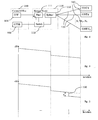
- Figure 2 is a simplified illustration of an exemplifying OTDR measurement in the PON of figure 1 when no events are detected.
- Figure 4 illustrates the method comprising triggering 410 a new OTDR measurement and inserting 420 an OTDR measurement signal into a multistage splitter before a last splitter stage of the multistage splitter.
- the last splitter stage is of ratio 2:N.
- Figure 4 further illustrates the method comprising obtaining 430 at least one new event location based on the OTDR measurement signal.
- the OTDR measurement signal travels down the fibre drop links, it will be subjected to an instant attenuation as illustrated in figure 2 .
- a corresponding event will be detected in the backscattered signal, as illustrated in figure 3 .
- the method further comprises calculating 440 a fault magnitude at a given location by subtracting an event magnitude obtained from the new OTDR measurement from a reference measurement and taking into account the number of drop links connected to the last splitter stage in reference measurement and the current or new measurement
- the event magnitude is the magnitude that is indicated in the OTDR measurement
- the fault magnitude is the actual magnitude of the fault thathas occurred in at least one fibre drop link.
- the insertion of an OTDR measurement signal is triggered by receiving 400 a fault alarm or an OTM measurement report from at least one ONT connected to the PON.
- the method further comprises querying the ONTs being connected to the PON about their received optical power periodically.
- resources can be saved by only querying the ONTs on demand.
- On-demand may be triggered manually or automatically as soon as an alarm is received from an ONT, the alarm indicating low received optical power.
- the multistage splitter may be able to support more ONTs than currently being connected thereto.
- the number of non-connected branches will affect the total loss. This will be explained in more detail below.
- an alarm or measurement report is received from one ONT and the number of new event locations is one and no events were detected in the reference measurement, wherein all the branches were connected to the splitter in the OTDR reference measurement and are also connected in the new OTDR measurement
- the magnitude, ⁇ , of the fault is the actual magnitude as opposed to the magnitude x of figure 1 , which is the magnitude of the event "seen" by the OTDR device as the backscattered light has passed the multistage splitter.
- an event is what is detected by the OTDR and a fault is what is calculated from the event
- FIG. 5 is a block diagram of an exemplifying client unit 510 in a Fibre Plant Manager, FPM, 500 adapted to perform fault analysis in a PON by using OTDR
- the client unit has the same objects and advantages as the method just described above and will only be discussed in brief, for simplicity reasons.
- Figure 5 illustrates the client unit 510 comprising an interface unit 511 and a processing unit 512.
- the processing unit 512 is adapted to trigger a new OTDR measurement wherein a previous reference measurement has been made indicating an original state of the PON.
- the processing unit 512 is further adapted to insert an OTDR measurement signal into a multistage splitter (not shown) before a last splitter stage of the multistage splitter, via the interface unit 511.
- the last splitter stage is of ratio 2:n.
- the processing unit 512 is further adapted to obtain atleast one new event location based on the OTDR measurement signal, via the interface unit 511.
- the processing unit 512 is further adapted to periodically query the ONTs being connected to the PON about their received optical power.
- processing unit511 is further adapted to query the ONTs being connected to the PON about their received optical power on-demand.
- the alarm is received from one ONT and the number of new event locations is one and no events were detected in the reference measurement further all the branches were connected to the splitter in the OTDR reference measurement and are connected in the new OTDR measurement
- the alarm is received from one ONTand the number of new event locations is j, j>1, and no events were detected in the reference measurement
- the alarm is received from n number of ONTs, n>1, and the number of new event locations is one and no events were detected in the reference measurement
- figure 5 merely illustrates various functional units in the client unit in a Fibre Plant Manager in a logical sense.
- the functions in practice may be implemented using any suitable software and hardware means/ circuits etc..
- the invention is generally not limited to the shown structures of the client unit and the functional units.
- the previously described exemplary embodiments may be realised in many ways.
- one embodiment of the present invention includes a computer-readable medium having instructions stored thereon that are executable by the client unit for executing the method.
- the instructions executable by the computing system and stored on the computer-readable medium perform the method steps of the present invention as set forth in the claims.
- the OTDR signal is in an example employed in the 1625-1675 nm band.
- the OTDRdevice 102 is typically located at the central office of a service provider.
- the OTDR device sends an OTDR measurement signal via a switch, e.g. an optical switch, through the last splitter stage of the multistage splitter 113 towards the ONTs 120-122.
- the OTDR signal is backscattered towards the OTDRdevice 102.
- the backscattered OTDR signal travels through the splitter on its way to the OTDR device.
- the OTDR device 102 "sees" the summation of backscattered signals from all drop links and also the magnitude of any event in a drop link is "falsified", meaning it is not the actual magnitude of the fault giving rise to the event
- Figure 7 is a schematic illustration of the last splitter stage 700 of a multistage splitter.
- Figure 7 illustrates a signal being inserted into the last splitter stage 700 having a power of Pin.
- the outgoing signals from the last splitter stage all have a power of Pin/ N. This is valid both if the incoming signal is a data signal and if the incoming/ inserted signal is an OTDR measurement signal. It is assumed here that the splitter divides its incoming signal uniformly to the outgoing signals.
- the last splitter stage is of ratio 2:N, wherein a first input comes from the previous splitter stage and a second input is a monitoring port
- a multistage splitter has two splitter stages, wherein the first splitter stage is 1:4 and the second splitter stage is 2:8. This results in the splitter having a total ratio of 1:32, wherein the second splitter stage has four monitoring ports.
- the incoming signal is an OTDR measurement signal
- it is inserted into the monitoring port of the last splitter stage.
- the input OTDR signal propagates from the monitor input port through the splitter and reaches the splitter output port Further on, the signals propagate along the fiber drop links. Part of each signal is backscattered due to Rayleigh Backscattering phenomena.
- the power level of the returned signal is proportional to the initial power at the splitter output port Pin/ N.
- the OTDR measurement takes into account the double loss that the signal experiences as the signal travels up and down the drop link, through the splitter. Due to this fact, the factor in front of the logarithm is "5" instead of "10".
- n,j is a linear factor describing the loss which the signal experiences in n-th fibre and at j-th location, corresponding to the distance on the fibre drop link This is also illustrated in figure 8 .
- Each row of the event matrix corresponds to a single fibre drop link
- Each column of the event matrix in figure 8 corresponds to a single location as indicated on the OTDR trace.
- ⁇ TL the difference in total loss between the reference OTDR measurement and the new OTDR measurement
- TLnew is the total loss in the new OTDR measurement and it may include possible additions or disconnections at the splitter output ports.
- Mref is the amountof non-connected drop links in the reference OTDR measurement and Mnew is the amount of non-connected drop links in the new OTDR measurement.
- Figure 9 is an illustration of an event/ fault scenario in which one event/ fault occurs in one fibre drop link
- ⁇ NEW dB 5 * log ⁇ 1 - N + N * 10 - ⁇ TL 5 .
- Figure 10 illustrates another scenario in which multiple events, in this example two events, occur in the same drop link fibre.
- the probability for this scenario to occur is relatively low with regards to the different scenarios that may occur as illustrated in figures 9-12 .
- figure 10 two events occur in the same fibre drop link.
- the following description regarding figure 10 will be more general, i.e. not limited to two faults.
- the total power difference in the fibre drop link experiencing the power difference is caused by J number of events as recorded by the OTDR measurement
- ⁇ NEWj dB 5 * log ⁇ 1 - N + N * 10 - ⁇ TLj 5 .
- ⁇ TIj is the loss from the beginning of the OTDR trace or measurement to the place where an analyzed event is detected with all the events on the way to the analyzed event and including the analyzed event
- the sum of all the ⁇ NEWj [dB] events should correspond to a power difference detected by or experienced by an ONT which is connected to fibre drop link subjected to the events.
- the analyzed events and its distances retrieved from OTDR trace can be assigned to a given fibre drop link Otherwise, the OTDR measurement should be repeated with better accuracy.
- OLT has initiated an alarm or reported a difference in received optical power, thereby it is known which fibre drop link is subjected to the events.
- fibre drop link is subjected to the event
- Figure 11 illustrates a scenario in which an event occurs in two different fibre drop links and at the same location at the two fibre drop links. The probability of this scenario to occur is relatively high in relation to the other scenarios illustrated in figures 9-12 .
- the OTDR trace or measurement will detect a single event overlapping in the two fibre drop links.
- the scenario illustrated in figure 11 can be generalized so that the OTDR trace or measurement will detect a single event overlapping in the multiple fibre drop links.
- the total power difference caused by the single event overlapping in multiple fibre drop links as detected by the OTDR measurement or trace can be defined as.
- the OTDRstep magnitude represents the real event magnitude reported by OTM.
- the OTDR step magnitude corresponds to the event magnitude x of figure 1 , i.e. the magnitude as "seen” by the OTDR device in the backscattered signal.
- ⁇ OTM n - ⁇ TL ⁇ ⁇ OTM .
- the analyzed events and their distances retrieved from OTDR trace can be assigned to a given fibre drop link Otherwise, the OTDR measurement should be repeated with better accuracy.
- the fibre drop link is given by which ONThas initiated an alarm or reported a difference in received optical power. Thereby, it is known which fibre drop link is subjected to the event
- Figure 12 is an illustration of an event/ fault scenario in which one event occurs in several fibre drop links at different locations in the different fibre drop links.
- Figure 14 illustrates the required number of monitor ports as a function of minimum detectable event magnitudes for different total split ratios per PON.
- the required number of monitor ports is based on equation (4) above.
- the required number of monitor ports as a function of minimum detectable event magnitudes is a trade-off between the sensitivity of the fault-detection system and its cost-efficiency.
Landscapes
- Physics & Mathematics (AREA)
- Optics & Photonics (AREA)
- Chemical & Material Sciences (AREA)
- Analytical Chemistry (AREA)
- General Physics & Mathematics (AREA)
- Electromagnetism (AREA)
- Engineering & Computer Science (AREA)
- Computer Networks & Wireless Communication (AREA)
- Signal Processing (AREA)
- Optical Communication System (AREA)
Claims (15)
- Procédé de réalisation d'analyse d'anomalie dans un réseau passif optique, PON, en utilisant une réflectométrie optique temporelle, OTDR, comprenant :- le déclenchement (410) d'une nouvelle mesure OTDR, dans lequel une mesure de référence précédente a été réalisée indiquant un état d'origine dudit PON,- l'insertion (420) d'un signal de mesure OTDR dans un diviseur multi-étage avant un dernier étage de diviseur dudit diviseur multi-étage, et dans lequel le dernier étage de diviseur est de rapport 2:N,- l'obtention (430) d'au moins une localisation de nouvel événement en fonction du signal de mesure OTDR, et- le calcul (440) d'une amplitude d'anomalie à une localisation donnée en soustrayant une amplitude d'événement obtenue, à partir de la nouvelle mesure OTDR, à partir de ladite mesure OTDR de référence et en prenant en compte le nombre de liaisons de branchement connectées au dernier étage de diviseur dans la mesure de référence et la nouvelle mesure,en permettant ainsi la détermination de la position et de la sévérité desdites localisations d'anomalie.
- Procédé selon la revendication 1, dans lequel la nouvelle mesure OTDR est déclenchée par la réception (400) d'une alarme d'anomalie ou d'un rapport de mesure de surveillance d'émetteur-récepteur optique, OTM, à partir d'au moins un terminal de réseau optique, ONT, connecté audit PON.
- Procédé selon la revendication 1 ou 2, comprenant en outre l'interrogation des ONT connectés audit PON en ce qui concerne leur puissance optique reçue périodiquement.
- Procédé selon une quelconque des revendications 1 à 3, comprenant en outre l'interrogation des ONT connectés audit PON en ce qui concerne leur puissance optique reçue à la demande.
- Procédé selon une quelconque des revendications 1 à 4, dans lequel une perte totale, TLref, dans ladite mesure OTDR de référence est représentée par :

où N est le nombre de branches du dernier étage de diviseur dudit diviseur multi-étage, J est le nombre d'événements et M est le nombre de branches non connectées dudit dernier étage de diviseur dudit diviseur multi-étage. - Procédé selon une quelconque des revendications 1 à 5, dans lequel une perte totale, TLnew, dans ladite nouvelle mesure OTDR est représentée par :

où N est le nombre de branches du dernier étage de diviseur dudit diviseur multi-étage, J est le nombre d'événements et M est le nombre de branches non connectées dudit dernier étage de diviseur dudit diviseur multi-étage. - Procédé selon la revendication 6, dans lequel la différence, ΔTL, entre ladite perte totale dans ladite mesure OTDR de référence et ladite perte totale dans ladite nouvelle mesure OTDR est représentée par

- Procédé selon une quelconque des revendications 1 à 7, dans lequel ladite alarme est reçue à partir d'un ONT et le nombre de localisations de nouvel événement est un et aucun événement n'a été détecté dans la mesure de référence, dans lequel toutes les branches étaient connectées audit diviseur dans ladite mesure de référence OTDR et sont connectés dans la nouvelle mesure OTDR, comprenant en outre le calcul de l'amplitude de l'anomalie, α, en utilisant

- Procédé selon une quelconque des revendications 1 à 7, dans lequel ladite alarme est reçue à partir d'un ONT et le nombre de localisations de nouvel événement est j, j > 1, et aucun événement n'a été détecté dans la mesure de référence, comprenant en outre le calcul de l'amplitude de l'anomalie dans le premier ONT, α, en utilisant

- Procédé selon une quelconque des revendications 1 à 7, dans lequel ladite alarme est reçue à partir d'un nombre n d'ONT, n > 1, et le nombre de localisations de nouvel événement est un et aucun événement n'a été détecté dans la mesure de référence, comprenant en outre le calcul de l'amplitude de l'anomalie dans le premier ONT, α, en utilisant

- Unité client (510) dans un gestionnaire d'installation à fibres (500) adapté pour réaliser une analyse d'anomalie dans un réseau optique passif, PON, en utilisant une réflectométrie optique temporelle, OTDR, comprenant :- une unité d'interface (511), et- une unité de traitement (512) adaptée pouren permettant ainsi la détermination de la position et de la sévérité desdites localisations d'anomalie.-- déclencher une nouvelle mesure OTDR, dans laquelle une mesure de référence précédente a été réalisée indiquant un état d'origine dudit PON,-- insérer un signal de mesure OTDR dans un diviseur multi-étage avant un dernier étage de diviseur dudit diviseur multi-étage, et dans laquelle le dernier étage de diviseur est de rapport 2:N, par l'intermédiaire de ladite unité d'interface (511),-- obtenir au moins une localisation de nouvel événement en fonction du signal de mesure OTDR, par l'intermédiaire de ladite unité d'interface et-- calculer une amplitude d'anomalie à une localisation donnée en soustrayant une amplitude d'événement obtenue à partir de la nouvelle mesure OTDR à partir de ladite mesure OTDR de référence et en prenant en compte le nombre de liaisons de branchement connectées au dernier étage de diviseur dans la mesure de référence et la nouvelle mesure,
- Unité client selon la revendication 11, dans laquelle ladite unité d'interface (511) est en outre adaptée pour recevoir une alarme d'anomalie ou un rapport de mesure de surveillance d'émetteur-récepteur optique, OTM, à partir d'au moins un terminal de réseau optique, ONT, connecté audit PON, dans laquelle ladite unité de traitement est déclenchée pour insérer ledit signal de mesure OTDR dans ledit diviseur multi-étage avant ledit dernier étage de diviseur dudit diviseur multi-étage.
- Unité client selon la revendication 11 ou 12, dans laquelle ladite unité de traitement (512) est en outre adaptée pour interroger périodiquement les ONT connectés audit PON en ce qui concerne leur puissance optique reçue.
- Unité client selon une quelconque des revendications 11 à 13, dans laquelle ladite unité de traitement (512) est en outre adaptée pour interroger les ONT connectés audit PON en ce qui concerne leur puissance optique reçue à la demande.
- Unité client selon une quelconque des revendications 11 à 14, dans laquelle ladite unité de traitement (512) est adaptée pour représenter une perte totale, TLref, dans ladite mesure OTDR de référence par

et pour représenter une perte totale, TLnew, dans ladite nouvelle mesure OTDR par
où N est le nombre de branches du dernier étage de diviseur dudit diviseur multi-étage, J est le nombre d'événements et M est le nombre de branches non connectées dudit dernier étage de diviseur dudit diviseur multi-étage.
Applications Claiming Priority (1)
| Application Number | Priority Date | Filing Date | Title |
|---|---|---|---|
| PCT/SE2010/051455 WO2012087205A1 (fr) | 2010-12-22 | 2010-12-22 | Analyse de trace otdr dans des systèmes pon |
Publications (2)
| Publication Number | Publication Date |
|---|---|
| EP2656515A1 EP2656515A1 (fr) | 2013-10-30 |
| EP2656515B1 true EP2656515B1 (fr) | 2015-02-18 |
Family
ID=44461821
Family Applications (1)
| Application Number | Title | Priority Date | Filing Date |
|---|---|---|---|
| EP10807500.3A Not-in-force EP2656515B1 (fr) | 2010-12-22 | 2010-12-22 | Analyse de trace otdr dans des systèmes pon |
Country Status (4)
| Country | Link |
|---|---|
| US (1) | US8724102B2 (fr) |
| EP (1) | EP2656515B1 (fr) |
| AR (1) | AR084526A1 (fr) |
| WO (1) | WO2012087205A1 (fr) |
Cited By (1)
| Publication number | Priority date | Publication date | Assignee | Title |
|---|---|---|---|---|
| EP3869709B1 (fr) * | 2020-02-18 | 2022-11-30 | Nokia Solutions and Networks Oy | Système de réflectométrie de domaine temporel optique (otdr) pour le diagnostic d'un réseau optique passif (pon) |
Families Citing this family (183)
| Publication number | Priority date | Publication date | Assignee | Title |
|---|---|---|---|---|
| WO2011053306A1 (fr) * | 2009-10-30 | 2011-05-05 | Hewlett-Packard Development Company, L.P. | Émetteur-récepteur optique ayant un mode de réflectomètre optique dans le domaine temporel et procédé d'obtention de données d'essai pour l'essai d'une fibre optique |
| CN106788694A (zh) | 2010-05-27 | 2017-05-31 | 爱斯福公司 | 多采集otdr方法及装置 |
| CN101924590B (zh) * | 2010-08-25 | 2016-04-13 | 中兴通讯股份有限公司 | 无源光网络光纤故障的检测系统和方法 |
| US9008503B2 (en) | 2011-03-21 | 2015-04-14 | Telefonaktiebolaget L M Ericsson (Publ) | Supervision of wavelength division multiplexed optical networks |
| US20120288273A1 (en) * | 2011-05-12 | 2012-11-15 | Alcatel-Lucent Usa, Inc. | Intelligent splitter monitor |
| US9287971B2 (en) | 2011-06-10 | 2016-03-15 | Telefonaktiebolaget L M Ericsson (Publ) | PON supervision using OTDR measurements |
| EP2726836B1 (fr) * | 2011-06-30 | 2020-06-24 | Telefonaktiebolaget LM Ericsson (publ) | Analyse de trace rdto dans des systèmes rop |
| US9344188B2 (en) | 2011-07-01 | 2016-05-17 | Telefonaktiebolaget L M Ericsson (Publ) | Device, remote node and methods for PON supervision |
| WO2013012361A1 (fr) | 2011-07-18 | 2013-01-24 | Telefonaktiebolaget Lm Ericsson (Publ) | Fonctionnalité otm dans des émetteurs-récepteurs basés sur un soa |
| EP2748577B1 (fr) | 2011-08-24 | 2018-02-28 | Telefonaktiebolaget LM Ericsson (publ) | Surveillance d'un réseau optique passif au moyen de mesures de réflectométrie optique temporelle |
| WO2013028110A1 (fr) | 2011-08-24 | 2013-02-28 | Telefonaktiebolaget Lm Ericsson (Publ) | Procédés et appareils pour la supervision de réseaux optiques |
| US8693866B1 (en) * | 2012-01-20 | 2014-04-08 | Google Inc. | Fiber diagnosis system for WDM optical access networks |
| GB2499386A (en) * | 2012-02-10 | 2013-08-21 | United Technologists Europe Ltd | OTDR Mapping Method using an optical reflector at a specific customer fibre end to increase the amplitude relative to other reflection events in the trace |
| TWM439789U (en) * | 2012-05-29 | 2012-10-21 | Polarlink Technologies Ltd | Detection and test device for inspecting optical fiber loss and individual event return loss of optic fiber line |
| US8948587B2 (en) | 2012-06-27 | 2015-02-03 | Centurylink Intellectual Property Llc | Use of dying gasp to locate faults in communications networks |
| US9219543B2 (en) * | 2012-07-11 | 2015-12-22 | Commscope Technologies Llc | Monitoring optical decay in fiber connectivity systems |
| CN102868446B (zh) * | 2012-09-20 | 2015-08-12 | 索尔思光电(成都)有限公司 | 一种使用双apd共用升压电路的olt光模块 |
| EP2909599A4 (fr) * | 2012-10-18 | 2016-06-29 | Ntest Inc | Systèmes d'analyse de perte d'un réseau optique passif |
| EP2920914B1 (fr) | 2012-11-15 | 2018-07-18 | Telefonaktiebolaget LM Ericsson (publ) | Procédé et système pour surveiller des lignes de transmission optiques |
| US9113347B2 (en) | 2012-12-05 | 2015-08-18 | At&T Intellectual Property I, Lp | Backhaul link for distributed antenna system |
| EP2750306A1 (fr) * | 2012-12-26 | 2014-07-02 | Alcatel Lucent | Procédé de diagnostique de la dégradation d'une liaison optique |
| CN103973362A (zh) * | 2013-02-06 | 2014-08-06 | 中兴通讯股份有限公司 | 设置otdr测试参数集的方法及装置 |
| CN103281122B (zh) * | 2013-04-28 | 2015-10-21 | 国家电网公司 | 一种光缆在线监测提高告警准确率的方法 |
| US9999038B2 (en) | 2013-05-31 | 2018-06-12 | At&T Intellectual Property I, L.P. | Remote distributed antenna system |
| US9525524B2 (en) | 2013-05-31 | 2016-12-20 | At&T Intellectual Property I, L.P. | Remote distributed antenna system |
| EP3005594A1 (fr) | 2013-06-04 | 2016-04-13 | Telefonaktiebolaget LM Ericsson (publ) | Émetteur-récepteur pour utilisation dans un réseau de fibres optiques |
| KR20150003602A (ko) * | 2013-07-01 | 2015-01-09 | 주식회사 케이티 | 광선로 상태 감시 장치 및 방법 |
| US9391695B2 (en) | 2013-07-10 | 2016-07-12 | Neophotonics Corporation | Optical network communication system with embedded optical time domain reflectometer and method of operation thereof |
| CN104301037A (zh) * | 2013-07-16 | 2015-01-21 | 中兴通讯股份有限公司 | 一种实现无源光网络光纤故障自动告警的方法及系统 |
| US9621262B1 (en) * | 2013-07-24 | 2017-04-11 | Optical Cable Corporation | Self-monitoring cable system |
| US9735866B2 (en) * | 2013-10-18 | 2017-08-15 | Telefonica, S.A. | Method, system and device for the supervision of optical fibres |
| US8897697B1 (en) | 2013-11-06 | 2014-11-25 | At&T Intellectual Property I, Lp | Millimeter-wave surface-wave communications |
| EP3114778B1 (fr) | 2014-03-03 | 2019-01-02 | Telefonaktiebolaget LM Ericsson (publ) | Émetteur-récepteur et procédé de surveillance de transmission scm sur câble à fibres optiques |
| US9768833B2 (en) | 2014-09-15 | 2017-09-19 | At&T Intellectual Property I, L.P. | Method and apparatus for sensing a condition in a transmission medium of electromagnetic waves |
| US10063280B2 (en) | 2014-09-17 | 2018-08-28 | At&T Intellectual Property I, L.P. | Monitoring and mitigating conditions in a communication network |
| US9615269B2 (en) | 2014-10-02 | 2017-04-04 | At&T Intellectual Property I, L.P. | Method and apparatus that provides fault tolerance in a communication network |
| US9685992B2 (en) | 2014-10-03 | 2017-06-20 | At&T Intellectual Property I, L.P. | Circuit panel network and methods thereof |
| US9503189B2 (en) | 2014-10-10 | 2016-11-22 | At&T Intellectual Property I, L.P. | Method and apparatus for arranging communication sessions in a communication system |
| US9762289B2 (en) | 2014-10-14 | 2017-09-12 | At&T Intellectual Property I, L.P. | Method and apparatus for transmitting or receiving signals in a transportation system |
| US9973299B2 (en) | 2014-10-14 | 2018-05-15 | At&T Intellectual Property I, L.P. | Method and apparatus for adjusting a mode of communication in a communication network |
| US9577306B2 (en) | 2014-10-21 | 2017-02-21 | At&T Intellectual Property I, L.P. | Guided-wave transmission device and methods for use therewith |
| US9780834B2 (en) | 2014-10-21 | 2017-10-03 | At&T Intellectual Property I, L.P. | Method and apparatus for transmitting electromagnetic waves |
| US9520945B2 (en) | 2014-10-21 | 2016-12-13 | At&T Intellectual Property I, L.P. | Apparatus for providing communication services and methods thereof |
| US9653770B2 (en) | 2014-10-21 | 2017-05-16 | At&T Intellectual Property I, L.P. | Guided wave coupler, coupling module and methods for use therewith |
| US9312919B1 (en) | 2014-10-21 | 2016-04-12 | At&T Intellectual Property I, Lp | Transmission device with impairment compensation and methods for use therewith |
| US9627768B2 (en) | 2014-10-21 | 2017-04-18 | At&T Intellectual Property I, L.P. | Guided-wave transmission device with non-fundamental mode propagation and methods for use therewith |
| US9769020B2 (en) | 2014-10-21 | 2017-09-19 | At&T Intellectual Property I, L.P. | Method and apparatus for responding to events affecting communications in a communication network |
| MX368131B (es) * | 2014-11-04 | 2019-09-19 | Afl Telecommunications Llc | Técnica de fusión para pistas de otdr capturadas al usar diferentes ajustes. |
| US9800327B2 (en) | 2014-11-20 | 2017-10-24 | At&T Intellectual Property I, L.P. | Apparatus for controlling operations of a communication device and methods thereof |
| US9954287B2 (en) | 2014-11-20 | 2018-04-24 | At&T Intellectual Property I, L.P. | Apparatus for converting wireless signals and electromagnetic waves and methods thereof |
| US10243784B2 (en) | 2014-11-20 | 2019-03-26 | At&T Intellectual Property I, L.P. | System for generating topology information and methods thereof |
| US10009067B2 (en) | 2014-12-04 | 2018-06-26 | At&T Intellectual Property I, L.P. | Method and apparatus for configuring a communication interface |
| US9461706B1 (en) | 2015-07-31 | 2016-10-04 | At&T Intellectual Property I, Lp | Method and apparatus for exchanging communication signals |
| US10340573B2 (en) | 2016-10-26 | 2019-07-02 | At&T Intellectual Property I, L.P. | Launcher with cylindrical coupling device and methods for use therewith |
| US9742462B2 (en) | 2014-12-04 | 2017-08-22 | At&T Intellectual Property I, L.P. | Transmission medium and communication interfaces and methods for use therewith |
| US9997819B2 (en) | 2015-06-09 | 2018-06-12 | At&T Intellectual Property I, L.P. | Transmission medium and method for facilitating propagation of electromagnetic waves via a core |
| US9544006B2 (en) | 2014-11-20 | 2017-01-10 | At&T Intellectual Property I, L.P. | Transmission device with mode division multiplexing and methods for use therewith |
| US9794658B2 (en) * | 2014-12-23 | 2017-10-17 | Infinera Corporation | Circuit diagnostic manager |
| US10144036B2 (en) | 2015-01-30 | 2018-12-04 | At&T Intellectual Property I, L.P. | Method and apparatus for mitigating interference affecting a propagation of electromagnetic waves guided by a transmission medium |
| US9876570B2 (en) | 2015-02-20 | 2018-01-23 | At&T Intellectual Property I, Lp | Guided-wave transmission device with non-fundamental mode propagation and methods for use therewith |
| US9641243B2 (en) | 2015-02-23 | 2017-05-02 | Exfo Inc. | Safe-mode OTDR method |
| KR20160112079A (ko) * | 2015-03-17 | 2016-09-28 | 한국전자통신연구원 | 광분배망에서의 광선로 검사 방법 및 그에 따른 검사 장치 |
| US9749013B2 (en) | 2015-03-17 | 2017-08-29 | At&T Intellectual Property I, L.P. | Method and apparatus for reducing attenuation of electromagnetic waves guided by a transmission medium |
| US10224981B2 (en) | 2015-04-24 | 2019-03-05 | At&T Intellectual Property I, Lp | Passive electrical coupling device and methods for use therewith |
| US9705561B2 (en) | 2015-04-24 | 2017-07-11 | At&T Intellectual Property I, L.P. | Directional coupling device and methods for use therewith |
| US9793954B2 (en) | 2015-04-28 | 2017-10-17 | At&T Intellectual Property I, L.P. | Magnetic coupling device and methods for use therewith |
| US9948354B2 (en) | 2015-04-28 | 2018-04-17 | At&T Intellectual Property I, L.P. | Magnetic coupling device with reflective plate and methods for use therewith |
| US9748626B2 (en) | 2015-05-14 | 2017-08-29 | At&T Intellectual Property I, L.P. | Plurality of cables having different cross-sectional shapes which are bundled together to form a transmission medium |
| US9490869B1 (en) | 2015-05-14 | 2016-11-08 | At&T Intellectual Property I, L.P. | Transmission medium having multiple cores and methods for use therewith |
| US9871282B2 (en) | 2015-05-14 | 2018-01-16 | At&T Intellectual Property I, L.P. | At least one transmission medium having a dielectric surface that is covered at least in part by a second dielectric |
| US10650940B2 (en) | 2015-05-15 | 2020-05-12 | At&T Intellectual Property I, L.P. | Transmission medium having a conductive material and methods for use therewith |
| US9917341B2 (en) | 2015-05-27 | 2018-03-13 | At&T Intellectual Property I, L.P. | Apparatus and method for launching electromagnetic waves and for modifying radial dimensions of the propagating electromagnetic waves |
| US9912381B2 (en) | 2015-06-03 | 2018-03-06 | At&T Intellectual Property I, Lp | Network termination and methods for use therewith |
| US10103801B2 (en) | 2015-06-03 | 2018-10-16 | At&T Intellectual Property I, L.P. | Host node device and methods for use therewith |
| US10812174B2 (en) | 2015-06-03 | 2020-10-20 | At&T Intellectual Property I, L.P. | Client node device and methods for use therewith |
| US9866309B2 (en) | 2015-06-03 | 2018-01-09 | At&T Intellectual Property I, Lp | Host node device and methods for use therewith |
| US9913139B2 (en) | 2015-06-09 | 2018-03-06 | At&T Intellectual Property I, L.P. | Signal fingerprinting for authentication of communicating devices |
| US9608692B2 (en) | 2015-06-11 | 2017-03-28 | At&T Intellectual Property I, L.P. | Repeater and methods for use therewith |
| US9820146B2 (en) | 2015-06-12 | 2017-11-14 | At&T Intellectual Property I, L.P. | Method and apparatus for authentication and identity management of communicating devices |
| US9667317B2 (en) | 2015-06-15 | 2017-05-30 | At&T Intellectual Property I, L.P. | Method and apparatus for providing security using network traffic adjustments |
| CN106330297B (zh) * | 2015-06-18 | 2020-06-05 | 中兴通讯股份有限公司 | 一种检测光纤故障点的方法和装置 |
| US9509415B1 (en) | 2015-06-25 | 2016-11-29 | At&T Intellectual Property I, L.P. | Methods and apparatus for inducing a fundamental wave mode on a transmission medium |
| US9865911B2 (en) | 2015-06-25 | 2018-01-09 | At&T Intellectual Property I, L.P. | Waveguide system for slot radiating first electromagnetic waves that are combined into a non-fundamental wave mode second electromagnetic wave on a transmission medium |
| US9640850B2 (en) | 2015-06-25 | 2017-05-02 | At&T Intellectual Property I, L.P. | Methods and apparatus for inducing a non-fundamental wave mode on a transmission medium |
| US9853342B2 (en) | 2015-07-14 | 2017-12-26 | At&T Intellectual Property I, L.P. | Dielectric transmission medium connector and methods for use therewith |
| US10341142B2 (en) | 2015-07-14 | 2019-07-02 | At&T Intellectual Property I, L.P. | Apparatus and methods for generating non-interfering electromagnetic waves on an uninsulated conductor |
| US10320586B2 (en) | 2015-07-14 | 2019-06-11 | At&T Intellectual Property I, L.P. | Apparatus and methods for generating non-interfering electromagnetic waves on an insulated transmission medium |
| US9722318B2 (en) | 2015-07-14 | 2017-08-01 | At&T Intellectual Property I, L.P. | Method and apparatus for coupling an antenna to a device |
| US9882257B2 (en) | 2015-07-14 | 2018-01-30 | At&T Intellectual Property I, L.P. | Method and apparatus for launching a wave mode that mitigates interference |
| US10033108B2 (en) | 2015-07-14 | 2018-07-24 | At&T Intellectual Property I, L.P. | Apparatus and methods for generating an electromagnetic wave having a wave mode that mitigates interference |
| US10205655B2 (en) | 2015-07-14 | 2019-02-12 | At&T Intellectual Property I, L.P. | Apparatus and methods for communicating utilizing an antenna array and multiple communication paths |
| US10170840B2 (en) | 2015-07-14 | 2019-01-01 | At&T Intellectual Property I, L.P. | Apparatus and methods for sending or receiving electromagnetic signals |
| US10148016B2 (en) | 2015-07-14 | 2018-12-04 | At&T Intellectual Property I, L.P. | Apparatus and methods for communicating utilizing an antenna array |
| US10044409B2 (en) | 2015-07-14 | 2018-08-07 | At&T Intellectual Property I, L.P. | Transmission medium and methods for use therewith |
| US9628116B2 (en) | 2015-07-14 | 2017-04-18 | At&T Intellectual Property I, L.P. | Apparatus and methods for transmitting wireless signals |
| US9847566B2 (en) | 2015-07-14 | 2017-12-19 | At&T Intellectual Property I, L.P. | Method and apparatus for adjusting a field of a signal to mitigate interference |
| US10090606B2 (en) | 2015-07-15 | 2018-10-02 | At&T Intellectual Property I, L.P. | Antenna system with dielectric array and methods for use therewith |
| US9793951B2 (en) | 2015-07-15 | 2017-10-17 | At&T Intellectual Property I, L.P. | Method and apparatus for launching a wave mode that mitigates interference |
| US9608740B2 (en) | 2015-07-15 | 2017-03-28 | At&T Intellectual Property I, L.P. | Method and apparatus for launching a wave mode that mitigates interference |
| US9948333B2 (en) | 2015-07-23 | 2018-04-17 | At&T Intellectual Property I, L.P. | Method and apparatus for wireless communications to mitigate interference |
| US9871283B2 (en) | 2015-07-23 | 2018-01-16 | At&T Intellectual Property I, Lp | Transmission medium having a dielectric core comprised of plural members connected by a ball and socket configuration |
| US9912027B2 (en) | 2015-07-23 | 2018-03-06 | At&T Intellectual Property I, L.P. | Method and apparatus for exchanging communication signals |
| US9749053B2 (en) | 2015-07-23 | 2017-08-29 | At&T Intellectual Property I, L.P. | Node device, repeater and methods for use therewith |
| US9735833B2 (en) | 2015-07-31 | 2017-08-15 | At&T Intellectual Property I, L.P. | Method and apparatus for communications management in a neighborhood network |
| US9967173B2 (en) | 2015-07-31 | 2018-05-08 | At&T Intellectual Property I, L.P. | Method and apparatus for authentication and identity management of communicating devices |
| US9904535B2 (en) | 2015-09-14 | 2018-02-27 | At&T Intellectual Property I, L.P. | Method and apparatus for distributing software |
| US10009063B2 (en) | 2015-09-16 | 2018-06-26 | At&T Intellectual Property I, L.P. | Method and apparatus for use with a radio distributed antenna system having an out-of-band reference signal |
| US10079661B2 (en) | 2015-09-16 | 2018-09-18 | At&T Intellectual Property I, L.P. | Method and apparatus for use with a radio distributed antenna system having a clock reference |
| US10136434B2 (en) | 2015-09-16 | 2018-11-20 | At&T Intellectual Property I, L.P. | Method and apparatus for use with a radio distributed antenna system having an ultra-wideband control channel |
| US9769128B2 (en) | 2015-09-28 | 2017-09-19 | At&T Intellectual Property I, L.P. | Method and apparatus for encryption of communications over a network |
| US9729197B2 (en) | 2015-10-01 | 2017-08-08 | At&T Intellectual Property I, L.P. | Method and apparatus for communicating network management traffic over a network |
| US9876264B2 (en) | 2015-10-02 | 2018-01-23 | At&T Intellectual Property I, Lp | Communication system, guided wave switch and methods for use therewith |
| US10355367B2 (en) | 2015-10-16 | 2019-07-16 | At&T Intellectual Property I, L.P. | Antenna structure for exchanging wireless signals |
| WO2017195953A1 (fr) * | 2016-05-09 | 2017-11-16 | 주식회사 인소프트 | Appareil de gestion intégrée destiné à surveiller et à mettre en œuvre une ligne optique et procédé de gestion intégrée associé |
| CN106059657A (zh) * | 2016-05-20 | 2016-10-26 | 烽火通信科技股份有限公司 | 一种集成光时域反射仪的光线路保护系统 |
| US9912419B1 (en) | 2016-08-24 | 2018-03-06 | At&T Intellectual Property I, L.P. | Method and apparatus for managing a fault in a distributed antenna system |
| US9860075B1 (en) | 2016-08-26 | 2018-01-02 | At&T Intellectual Property I, L.P. | Method and communication node for broadband distribution |
| US10291311B2 (en) | 2016-09-09 | 2019-05-14 | At&T Intellectual Property I, L.P. | Method and apparatus for mitigating a fault in a distributed antenna system |
| US11032819B2 (en) | 2016-09-15 | 2021-06-08 | At&T Intellectual Property I, L.P. | Method and apparatus for use with a radio distributed antenna system having a control channel reference signal |
| US10135147B2 (en) | 2016-10-18 | 2018-11-20 | At&T Intellectual Property I, L.P. | Apparatus and methods for launching guided waves via an antenna |
| US10340600B2 (en) | 2016-10-18 | 2019-07-02 | At&T Intellectual Property I, L.P. | Apparatus and methods for launching guided waves via plural waveguide systems |
| US10135146B2 (en) | 2016-10-18 | 2018-11-20 | At&T Intellectual Property I, L.P. | Apparatus and methods for launching guided waves via circuits |
| US9876605B1 (en) | 2016-10-21 | 2018-01-23 | At&T Intellectual Property I, L.P. | Launcher and coupling system to support desired guided wave mode |
| US10811767B2 (en) | 2016-10-21 | 2020-10-20 | At&T Intellectual Property I, L.P. | System and dielectric antenna with convex dielectric radome |
| US10374316B2 (en) | 2016-10-21 | 2019-08-06 | At&T Intellectual Property I, L.P. | System and dielectric antenna with non-uniform dielectric |
| US9991580B2 (en) | 2016-10-21 | 2018-06-05 | At&T Intellectual Property I, L.P. | Launcher and coupling system for guided wave mode cancellation |
| US10312567B2 (en) | 2016-10-26 | 2019-06-04 | At&T Intellectual Property I, L.P. | Launcher with planar strip antenna and methods for use therewith |
| US10224634B2 (en) | 2016-11-03 | 2019-03-05 | At&T Intellectual Property I, L.P. | Methods and apparatus for adjusting an operational characteristic of an antenna |
| US10225025B2 (en) | 2016-11-03 | 2019-03-05 | At&T Intellectual Property I, L.P. | Method and apparatus for detecting a fault in a communication system |
| US10498044B2 (en) | 2016-11-03 | 2019-12-03 | At&T Intellectual Property I, L.P. | Apparatus for configuring a surface of an antenna |
| US10291334B2 (en) | 2016-11-03 | 2019-05-14 | At&T Intellectual Property I, L.P. | System for detecting a fault in a communication system |
| US10178445B2 (en) | 2016-11-23 | 2019-01-08 | At&T Intellectual Property I, L.P. | Methods, devices, and systems for load balancing between a plurality of waveguides |
| US10340603B2 (en) | 2016-11-23 | 2019-07-02 | At&T Intellectual Property I, L.P. | Antenna system having shielded structural configurations for assembly |
| US10535928B2 (en) | 2016-11-23 | 2020-01-14 | At&T Intellectual Property I, L.P. | Antenna system and methods for use therewith |
| US10090594B2 (en) | 2016-11-23 | 2018-10-02 | At&T Intellectual Property I, L.P. | Antenna system having structural configurations for assembly |
| US10340601B2 (en) | 2016-11-23 | 2019-07-02 | At&T Intellectual Property I, L.P. | Multi-antenna system and methods for use therewith |
| US10305190B2 (en) | 2016-12-01 | 2019-05-28 | At&T Intellectual Property I, L.P. | Reflecting dielectric antenna system and methods for use therewith |
| US10361489B2 (en) | 2016-12-01 | 2019-07-23 | At&T Intellectual Property I, L.P. | Dielectric dish antenna system and methods for use therewith |
| US10694379B2 (en) | 2016-12-06 | 2020-06-23 | At&T Intellectual Property I, L.P. | Waveguide system with device-based authentication and methods for use therewith |
| US10819035B2 (en) | 2016-12-06 | 2020-10-27 | At&T Intellectual Property I, L.P. | Launcher with helical antenna and methods for use therewith |
| US10135145B2 (en) | 2016-12-06 | 2018-11-20 | At&T Intellectual Property I, L.P. | Apparatus and methods for generating an electromagnetic wave along a transmission medium |
| US10326494B2 (en) | 2016-12-06 | 2019-06-18 | At&T Intellectual Property I, L.P. | Apparatus for measurement de-embedding and methods for use therewith |
| US10727599B2 (en) | 2016-12-06 | 2020-07-28 | At&T Intellectual Property I, L.P. | Launcher with slot antenna and methods for use therewith |
| US10439675B2 (en) | 2016-12-06 | 2019-10-08 | At&T Intellectual Property I, L.P. | Method and apparatus for repeating guided wave communication signals |
| US10382976B2 (en) | 2016-12-06 | 2019-08-13 | At&T Intellectual Property I, L.P. | Method and apparatus for managing wireless communications based on communication paths and network device positions |
| US10755542B2 (en) | 2016-12-06 | 2020-08-25 | At&T Intellectual Property I, L.P. | Method and apparatus for surveillance via guided wave communication |
| US10020844B2 (en) | 2016-12-06 | 2018-07-10 | T&T Intellectual Property I, L.P. | Method and apparatus for broadcast communication via guided waves |
| US10637149B2 (en) | 2016-12-06 | 2020-04-28 | At&T Intellectual Property I, L.P. | Injection molded dielectric antenna and methods for use therewith |
| US9927517B1 (en) | 2016-12-06 | 2018-03-27 | At&T Intellectual Property I, L.P. | Apparatus and methods for sensing rainfall |
| US10389029B2 (en) | 2016-12-07 | 2019-08-20 | At&T Intellectual Property I, L.P. | Multi-feed dielectric antenna system with core selection and methods for use therewith |
| US10547348B2 (en) | 2016-12-07 | 2020-01-28 | At&T Intellectual Property I, L.P. | Method and apparatus for switching transmission mediums in a communication system |
| US10027397B2 (en) | 2016-12-07 | 2018-07-17 | At&T Intellectual Property I, L.P. | Distributed antenna system and methods for use therewith |
| US10139820B2 (en) | 2016-12-07 | 2018-11-27 | At&T Intellectual Property I, L.P. | Method and apparatus for deploying equipment of a communication system |
| US10243270B2 (en) | 2016-12-07 | 2019-03-26 | At&T Intellectual Property I, L.P. | Beam adaptive multi-feed dielectric antenna system and methods for use therewith |
| US10359749B2 (en) | 2016-12-07 | 2019-07-23 | At&T Intellectual Property I, L.P. | Method and apparatus for utilities management via guided wave communication |
| US10168695B2 (en) | 2016-12-07 | 2019-01-01 | At&T Intellectual Property I, L.P. | Method and apparatus for controlling an unmanned aircraft |
| US9893795B1 (en) | 2016-12-07 | 2018-02-13 | At&T Intellectual Property I, Lp | Method and repeater for broadband distribution |
| US10446936B2 (en) | 2016-12-07 | 2019-10-15 | At&T Intellectual Property I, L.P. | Multi-feed dielectric antenna system and methods for use therewith |
| US10777873B2 (en) | 2016-12-08 | 2020-09-15 | At&T Intellectual Property I, L.P. | Method and apparatus for mounting network devices |
| US10411356B2 (en) | 2016-12-08 | 2019-09-10 | At&T Intellectual Property I, L.P. | Apparatus and methods for selectively targeting communication devices with an antenna array |
| US10326689B2 (en) | 2016-12-08 | 2019-06-18 | At&T Intellectual Property I, L.P. | Method and system for providing alternative communication paths |
| US10103422B2 (en) | 2016-12-08 | 2018-10-16 | At&T Intellectual Property I, L.P. | Method and apparatus for mounting network devices |
| US10938108B2 (en) | 2016-12-08 | 2021-03-02 | At&T Intellectual Property I, L.P. | Frequency selective multi-feed dielectric antenna system and methods for use therewith |
| US10601494B2 (en) | 2016-12-08 | 2020-03-24 | At&T Intellectual Property I, L.P. | Dual-band communication device and method for use therewith |
| US10530505B2 (en) | 2016-12-08 | 2020-01-07 | At&T Intellectual Property I, L.P. | Apparatus and methods for launching electromagnetic waves along a transmission medium |
| US10389037B2 (en) | 2016-12-08 | 2019-08-20 | At&T Intellectual Property I, L.P. | Apparatus and methods for selecting sections of an antenna array and use therewith |
| US10916969B2 (en) | 2016-12-08 | 2021-02-09 | At&T Intellectual Property I, L.P. | Method and apparatus for providing power using an inductive coupling |
| US9998870B1 (en) | 2016-12-08 | 2018-06-12 | At&T Intellectual Property I, L.P. | Method and apparatus for proximity sensing |
| US10069535B2 (en) | 2016-12-08 | 2018-09-04 | At&T Intellectual Property I, L.P. | Apparatus and methods for launching electromagnetic waves having a certain electric field structure |
| US9911020B1 (en) | 2016-12-08 | 2018-03-06 | At&T Intellectual Property I, L.P. | Method and apparatus for tracking via a radio frequency identification device |
| US10264586B2 (en) | 2016-12-09 | 2019-04-16 | At&T Mobility Ii Llc | Cloud-based packet controller and methods for use therewith |
| US10340983B2 (en) | 2016-12-09 | 2019-07-02 | At&T Intellectual Property I, L.P. | Method and apparatus for surveying remote sites via guided wave communications |
| US9838896B1 (en) | 2016-12-09 | 2017-12-05 | At&T Intellectual Property I, L.P. | Method and apparatus for assessing network coverage |
| US9973940B1 (en) | 2017-02-27 | 2018-05-15 | At&T Intellectual Property I, L.P. | Apparatus and methods for dynamic impedance matching of a guided wave launcher |
| US10298293B2 (en) | 2017-03-13 | 2019-05-21 | At&T Intellectual Property I, L.P. | Apparatus of communication utilizing wireless network devices |
| CN109768827B (zh) * | 2018-12-26 | 2020-05-08 | 东南大学 | 一种二维光编解码系统的链路状态识别方法 |
| EP3681057B1 (fr) * | 2019-01-14 | 2022-05-04 | Nokia Solutions and Networks Oy | Surveillance de signaux dans un réseau optique passif |
| US11650128B2 (en) | 2020-06-30 | 2023-05-16 | Exfo Inc. | Optical fiber recognition using backscattering pattern |
| US11879802B2 (en) * | 2020-10-22 | 2024-01-23 | Exfo Inc. | Testing optical fiber link continuity using OTDR backscattering patterns |
| EP3996296A1 (fr) * | 2020-11-05 | 2022-05-11 | Viavi Solutions Inc. | Certification de liaison par fibre optique basée sur la détection d'événements et la mesure du niveau de puissance lumineuse par réflectomètre de domaine temporel optique (otdr) |
| US11606139B2 (en) | 2021-03-08 | 2023-03-14 | At&T Intellectual Property I, L.P. | Multi-path, smart optical time-domain reflectometer |
| US11923893B2 (en) | 2021-07-19 | 2024-03-05 | At&T Intellectual Property I, L.P. | Port-identified optical signal splitter |
| CN116192245A (zh) * | 2022-12-27 | 2023-05-30 | 湖北华网控股集团有限公司 | 基于pon网络的故障诊断方法、系统、设备及存储介质 |
Family Cites Families (29)
| Publication number | Priority date | Publication date | Assignee | Title |
|---|---|---|---|---|
| GB9202564D0 (en) * | 1992-02-07 | 1992-03-25 | Marconi Gec Ltd | Optical signal transmission network |
| JP3292982B2 (ja) * | 1997-10-09 | 2002-06-17 | アンリツ株式会社 | 光ファイバ特性評価装置及びプログラムを記録した媒体 |
| JP4055306B2 (ja) | 1999-11-08 | 2008-03-05 | 富士通株式会社 | 伝送路の障害検出装置及び方法 |
| US6396573B1 (en) | 2000-02-17 | 2002-05-28 | Fitel U.S.A. Corp. | System and method for optically testing broadcasting systems |
| US6396575B1 (en) | 2000-05-31 | 2002-05-28 | Lucent Technologies Inc. | Test and measurement system for detecting and monitoring faults and losses in passive optical networks (PONs) |
| EP1624593A1 (fr) | 2004-08-05 | 2006-02-08 | Alcatel | Méthode et système de surveillance d'un réseau de distribution optique |
| KR100687710B1 (ko) | 2004-11-20 | 2007-02-27 | 한국전자통신연구원 | 수동형 광가입자망 시스템에서의 광선로 감시 방법 및 장치 |
| DE602005026439D1 (de) | 2004-12-17 | 2011-03-31 | British Telecomm Public Ltd Co | Netzwerkbeurteilung |
| EP1856825A2 (fr) * | 2005-03-07 | 2007-11-21 | Nettest North America, Inc. | Dispositif de mesure de pertes dans des reseaux optiques passifs et procede d'utilisation |
| CN101860398B (zh) * | 2006-02-03 | 2013-02-20 | 株式会社藤仓 | 光线路监视装置和光线路监视方法 |
| US7715718B2 (en) * | 2006-08-01 | 2010-05-11 | Alcatel Lucent | Passive optical network optical time-domain reflectometry |
| TWI350071B (en) | 2006-09-11 | 2011-10-01 | Univ Nat Taiwan Science Tech | Detection system for identifying faults in a passive optical network |
| ATE499760T1 (de) | 2007-04-26 | 2011-03-15 | Alcatel Lucent | Überwachungseinheit, optisches netzwerk und betriebsverfahren für das optische netzwerk |
| EP1986351B1 (fr) | 2007-04-26 | 2010-02-24 | Alcatel Lucent | Réseau optique, unité de surveillance et procédé de surveillance |
| US7684702B2 (en) | 2007-05-21 | 2010-03-23 | Inventec Multimedia & Telecom Corporation | Optical link monitoring system and method for passive optical network |
| ATE506771T1 (de) * | 2008-02-04 | 2011-05-15 | Alcatel Lucent | Verfahren zur koordination von messungen und kalibrierungen in einem passiven optischen netzwerk |
| ES2656788T3 (es) * | 2008-05-09 | 2018-02-28 | Afl Telecommunications Llc | Reflectómetro óptico en el dominio del tiempo |
| PT2284514E (pt) * | 2008-06-02 | 2016-01-13 | Sumitomo Electric Industries | Dispositivo de monitorização de trajectória de feixe, e sistema de monitorização de trajectória de feixe |
| US8090258B2 (en) * | 2008-09-19 | 2012-01-03 | Tellabs Petaluma, Inc. | Method and apparatus for correcting faults in a passive optical network |
| GB0823688D0 (en) * | 2008-12-31 | 2009-02-04 | Tyco Electronics Raychem Nv | Unidirectional absolute optical attenuation measurement with OTDR |
| EP2209226B1 (fr) * | 2009-01-19 | 2013-07-24 | Nokia Siemens Networks OY | Procédé et dispositif de traitement de signaux dans une unité de réseau optique |
| CN107017941A (zh) | 2009-04-30 | 2017-08-04 | 瑞典爱立信有限公司 | 用于无源光网络(pon)中的故障发现的方法和装置 |
| JP5493571B2 (ja) * | 2009-08-06 | 2014-05-14 | 住友電気工業株式会社 | Otdr波形判定方法 |
| CN102244539B (zh) * | 2010-05-11 | 2014-09-17 | 华为技术有限公司 | 分支光纤检测方法及系统、无源光网络和分光器 |
| IL206723A0 (en) * | 2010-06-30 | 2010-12-30 | Eci Telecom Ltd | Technology for fault allocation in passive optical networks (pon) |
| EP2726836B1 (fr) * | 2011-06-30 | 2020-06-24 | Telefonaktiebolaget LM Ericsson (publ) | Analyse de trace rdto dans des systèmes rop |
| WO2013028110A1 (fr) * | 2011-08-24 | 2013-02-28 | Telefonaktiebolaget Lm Ericsson (Publ) | Procédés et appareils pour la supervision de réseaux optiques |
| EP2748577B1 (fr) * | 2011-08-24 | 2018-02-28 | Telefonaktiebolaget LM Ericsson (publ) | Surveillance d'un réseau optique passif au moyen de mesures de réflectométrie optique temporelle |
| WO2013169150A1 (fr) * | 2012-05-07 | 2013-11-14 | Telefonaktiebolaget Lm Ericsson (Publ) | Surveillance d'un réseau pon |
-
2010
- 2010-12-22 US US12/976,954 patent/US8724102B2/en active Active
- 2010-12-22 EP EP10807500.3A patent/EP2656515B1/fr not_active Not-in-force
- 2010-12-22 WO PCT/SE2010/051455 patent/WO2012087205A1/fr active Application Filing
-
2011
- 2011-12-21 AR ARP110104867A patent/AR084526A1/es not_active Application Discontinuation
Cited By (1)
| Publication number | Priority date | Publication date | Assignee | Title |
|---|---|---|---|---|
| EP3869709B1 (fr) * | 2020-02-18 | 2022-11-30 | Nokia Solutions and Networks Oy | Système de réflectométrie de domaine temporel optique (otdr) pour le diagnostic d'un réseau optique passif (pon) |
Also Published As
| Publication number | Publication date |
|---|---|
| AR084526A1 (es) | 2013-05-22 |
| US20120163800A1 (en) | 2012-06-28 |
| WO2012087205A1 (fr) | 2012-06-28 |
| EP2656515A1 (fr) | 2013-10-30 |
| US8724102B2 (en) | 2014-05-13 |
Similar Documents
| Publication | Publication Date | Title |
|---|---|---|
| EP2656515B1 (fr) | Analyse de trace otdr dans des systèmes pon | |
| US9281892B2 (en) | OTDR trace analysis in PON systems | |
| AU2009304512B2 (en) | Method and apparatus for deriving parameters of optical paths in optical networks using a two-wavelength otdr and a wavelength-dependent reflective element | |
| KR101657329B1 (ko) | 수동 광통신 망에서 오류를 발견하기 위한 방법과 장치 | |
| US8270828B2 (en) | Optical line monitoring apparatus and optical line monitoring method | |
| AU617913B2 (en) | Loss detection | |
| EP2828634B1 (fr) | Système, isolateur de longueur d'onde et procédés associés de surveillance d'un réseau optique passif | |
| Toge et al. | Recent research and development of optical fiber monitoring in communication systems | |
| Parkin et al. | Gigabit SFP transceiver with integrated optical time domain reflectometer for ethernet access services | |
| Ito et al. | End-reflection assisted brillouin measurement for PON monitoring | |
| JP4819165B2 (ja) | 光通信システム及びその監視方法 | |
| EP3996296A1 (fr) | Certification de liaison par fibre optique basée sur la détection d'événements et la mesure du niveau de puissance lumineuse par réflectomètre de domaine temporel optique (otdr) | |
| CN114189280B (zh) | 一种光时域反射仪多波长可带光测试的方法 | |
| WO2022099552A1 (fr) | Système et procédé de surveillance de performance de fibres en temps réel | |
| JP3295595B2 (ja) | 光ファイバ式物理量計測システム | |
| JP2674659B2 (ja) | 光線路監視方法 | |
| Lutchenko et al. | Simulation of readiness coefficient of FOCL with temperature actions on optical fibers |
Legal Events
| Date | Code | Title | Description |
|---|---|---|---|
| PUAI | Public reference made under article 153(3) epc to a published international application that has entered the european phase |
Free format text: ORIGINAL CODE: 0009012 |
|
| 17P | Request for examination filed |
Effective date: 20130711 |
|
| AK | Designated contracting states |
Kind code of ref document: A1 Designated state(s): AL AT BE BG CH CY CZ DE DK EE ES FI FR GB GR HR HU IE IS IT LI LT LU LV MC MK MT NL NO PL PT RO RS SE SI SK SM TR |
|
| DAX | Request for extension of the european patent (deleted) | ||
| REG | Reference to a national code |
Ref country code: DE Ref legal event code: R079 Ref document number: 602010022372 Country of ref document: DE Free format text: PREVIOUS MAIN CLASS: H04B0010080000 Ipc: H04B0010071000 |
|
| RIC1 | Information provided on ipc code assigned before grant |
Ipc: G01M 11/00 20060101ALI20140729BHEP Ipc: H04B 10/071 20130101AFI20140729BHEP |
|
| GRAP | Despatch of communication of intention to grant a patent |
Free format text: ORIGINAL CODE: EPIDOSNIGR1 |
|
| INTG | Intention to grant announced |
Effective date: 20140919 |
|
| GRAS | Grant fee paid |
Free format text: ORIGINAL CODE: EPIDOSNIGR3 |
|
| GRAA | (expected) grant |
Free format text: ORIGINAL CODE: 0009210 |
|
| AK | Designated contracting states |
Kind code of ref document: B1 Designated state(s): AL AT BE BG CH CY CZ DE DK EE ES FI FR GB GR HR HU IE IS IT LI LT LU LV MC MK MT NL NO PL PT RO RS SE SI SK SM TR |
|
| REG | Reference to a national code |
Ref country code: GB Ref legal event code: FG4D |
|
| REG | Reference to a national code |
Ref country code: CH Ref legal event code: EP |
|
| REG | Reference to a national code |
Ref country code: AT Ref legal event code: REF Ref document number: 711022 Country of ref document: AT Kind code of ref document: T Effective date: 20150315 |
|
| REG | Reference to a national code |
Ref country code: NL Ref legal event code: T3 Ref country code: IE Ref legal event code: FG4D |
|
| REG | Reference to a national code |
Ref country code: DE Ref legal event code: R096 Ref document number: 602010022372 Country of ref document: DE Effective date: 20150326 |
|
| REG | Reference to a national code |
Ref country code: AT Ref legal event code: MK05 Ref document number: 711022 Country of ref document: AT Kind code of ref document: T Effective date: 20150218 |
|
| REG | Reference to a national code |
Ref country code: LT Ref legal event code: MG4D |
|
| PG25 | Lapsed in a contracting state [announced via postgrant information from national office to epo] |
Ref country code: NO Free format text: LAPSE BECAUSE OF FAILURE TO SUBMIT A TRANSLATION OF THE DESCRIPTION OR TO PAY THE FEE WITHIN THE PRESCRIBED TIME-LIMIT Effective date: 20150518 Ref country code: FI Free format text: LAPSE BECAUSE OF FAILURE TO SUBMIT A TRANSLATION OF THE DESCRIPTION OR TO PAY THE FEE WITHIN THE PRESCRIBED TIME-LIMIT Effective date: 20150218 Ref country code: SE Free format text: LAPSE BECAUSE OF FAILURE TO SUBMIT A TRANSLATION OF THE DESCRIPTION OR TO PAY THE FEE WITHIN THE PRESCRIBED TIME-LIMIT Effective date: 20150218 Ref country code: LT Free format text: LAPSE BECAUSE OF FAILURE TO SUBMIT A TRANSLATION OF THE DESCRIPTION OR TO PAY THE FEE WITHIN THE PRESCRIBED TIME-LIMIT Effective date: 20150218 Ref country code: HR Free format text: LAPSE BECAUSE OF FAILURE TO SUBMIT A TRANSLATION OF THE DESCRIPTION OR TO PAY THE FEE WITHIN THE PRESCRIBED TIME-LIMIT Effective date: 20150218 Ref country code: ES Free format text: LAPSE BECAUSE OF FAILURE TO SUBMIT A TRANSLATION OF THE DESCRIPTION OR TO PAY THE FEE WITHIN THE PRESCRIBED TIME-LIMIT Effective date: 20150218 |
|
| PG25 | Lapsed in a contracting state [announced via postgrant information from national office to epo] |
Ref country code: AT Free format text: LAPSE BECAUSE OF FAILURE TO SUBMIT A TRANSLATION OF THE DESCRIPTION OR TO PAY THE FEE WITHIN THE PRESCRIBED TIME-LIMIT Effective date: 20150218 Ref country code: RS Free format text: LAPSE BECAUSE OF FAILURE TO SUBMIT A TRANSLATION OF THE DESCRIPTION OR TO PAY THE FEE WITHIN THE PRESCRIBED TIME-LIMIT Effective date: 20150218 Ref country code: GR Free format text: LAPSE BECAUSE OF FAILURE TO SUBMIT A TRANSLATION OF THE DESCRIPTION OR TO PAY THE FEE WITHIN THE PRESCRIBED TIME-LIMIT Effective date: 20150519 Ref country code: IS Free format text: LAPSE BECAUSE OF FAILURE TO SUBMIT A TRANSLATION OF THE DESCRIPTION OR TO PAY THE FEE WITHIN THE PRESCRIBED TIME-LIMIT Effective date: 20150618 Ref country code: LV Free format text: LAPSE BECAUSE OF FAILURE TO SUBMIT A TRANSLATION OF THE DESCRIPTION OR TO PAY THE FEE WITHIN THE PRESCRIBED TIME-LIMIT Effective date: 20150218 |
|
| PG25 | Lapsed in a contracting state [announced via postgrant information from national office to epo] |
Ref country code: RO Free format text: LAPSE BECAUSE OF FAILURE TO SUBMIT A TRANSLATION OF THE DESCRIPTION OR TO PAY THE FEE WITHIN THE PRESCRIBED TIME-LIMIT Effective date: 20150218 Ref country code: DK Free format text: LAPSE BECAUSE OF FAILURE TO SUBMIT A TRANSLATION OF THE DESCRIPTION OR TO PAY THE FEE WITHIN THE PRESCRIBED TIME-LIMIT Effective date: 20150218 Ref country code: SK Free format text: LAPSE BECAUSE OF FAILURE TO SUBMIT A TRANSLATION OF THE DESCRIPTION OR TO PAY THE FEE WITHIN THE PRESCRIBED TIME-LIMIT Effective date: 20150218 Ref country code: CZ Free format text: LAPSE BECAUSE OF FAILURE TO SUBMIT A TRANSLATION OF THE DESCRIPTION OR TO PAY THE FEE WITHIN THE PRESCRIBED TIME-LIMIT Effective date: 20150218 Ref country code: EE Free format text: LAPSE BECAUSE OF FAILURE TO SUBMIT A TRANSLATION OF THE DESCRIPTION OR TO PAY THE FEE WITHIN THE PRESCRIBED TIME-LIMIT Effective date: 20150218 |
|
| REG | Reference to a national code |
Ref country code: DE Ref legal event code: R097 Ref document number: 602010022372 Country of ref document: DE |
|
| PG25 | Lapsed in a contracting state [announced via postgrant information from national office to epo] |
Ref country code: PL Free format text: LAPSE BECAUSE OF FAILURE TO SUBMIT A TRANSLATION OF THE DESCRIPTION OR TO PAY THE FEE WITHIN THE PRESCRIBED TIME-LIMIT Effective date: 20150218 |
|
| PLBE | No opposition filed within time limit |
Free format text: ORIGINAL CODE: 0009261 |
|
| STAA | Information on the status of an ep patent application or granted ep patent |
Free format text: STATUS: NO OPPOSITION FILED WITHIN TIME LIMIT |
|
| PG25 | Lapsed in a contracting state [announced via postgrant information from national office to epo] |
Ref country code: IT Free format text: LAPSE BECAUSE OF FAILURE TO SUBMIT A TRANSLATION OF THE DESCRIPTION OR TO PAY THE FEE WITHIN THE PRESCRIBED TIME-LIMIT Effective date: 20150218 |
|
| 26N | No opposition filed |
Effective date: 20151119 |
|
| PG25 | Lapsed in a contracting state [announced via postgrant information from national office to epo] |
Ref country code: SI Free format text: LAPSE BECAUSE OF FAILURE TO SUBMIT A TRANSLATION OF THE DESCRIPTION OR TO PAY THE FEE WITHIN THE PRESCRIBED TIME-LIMIT Effective date: 20150218 |
|
| PG25 | Lapsed in a contracting state [announced via postgrant information from national office to epo] |
Ref country code: BE Free format text: LAPSE BECAUSE OF FAILURE TO SUBMIT A TRANSLATION OF THE DESCRIPTION OR TO PAY THE FEE WITHIN THE PRESCRIBED TIME-LIMIT Effective date: 20150218 |
|
| PG25 | Lapsed in a contracting state [announced via postgrant information from national office to epo] |
Ref country code: LU Free format text: LAPSE BECAUSE OF FAILURE TO SUBMIT A TRANSLATION OF THE DESCRIPTION OR TO PAY THE FEE WITHIN THE PRESCRIBED TIME-LIMIT Effective date: 20151222 Ref country code: MC Free format text: LAPSE BECAUSE OF FAILURE TO SUBMIT A TRANSLATION OF THE DESCRIPTION OR TO PAY THE FEE WITHIN THE PRESCRIBED TIME-LIMIT Effective date: 20150218 |
|
| REG | Reference to a national code |
Ref country code: CH Ref legal event code: PL |
|
| REG | Reference to a national code |
Ref country code: IE Ref legal event code: MM4A |
|
| REG | Reference to a national code |
Ref country code: FR Ref legal event code: ST Effective date: 20160831 |
|
| PG25 | Lapsed in a contracting state [announced via postgrant information from national office to epo] |
Ref country code: LI Free format text: LAPSE BECAUSE OF NON-PAYMENT OF DUE FEES Effective date: 20151231 Ref country code: CH Free format text: LAPSE BECAUSE OF NON-PAYMENT OF DUE FEES Effective date: 20151231 Ref country code: IE Free format text: LAPSE BECAUSE OF NON-PAYMENT OF DUE FEES Effective date: 20151222 |
|
| PG25 | Lapsed in a contracting state [announced via postgrant information from national office to epo] |
Ref country code: FR Free format text: LAPSE BECAUSE OF NON-PAYMENT OF DUE FEES Effective date: 20151231 |
|
| PG25 | Lapsed in a contracting state [announced via postgrant information from national office to epo] |
Ref country code: BG Free format text: LAPSE BECAUSE OF FAILURE TO SUBMIT A TRANSLATION OF THE DESCRIPTION OR TO PAY THE FEE WITHIN THE PRESCRIBED TIME-LIMIT Effective date: 20150218 Ref country code: HU Free format text: LAPSE BECAUSE OF FAILURE TO SUBMIT A TRANSLATION OF THE DESCRIPTION OR TO PAY THE FEE WITHIN THE PRESCRIBED TIME-LIMIT; INVALID AB INITIO Effective date: 20101222 Ref country code: SM Free format text: LAPSE BECAUSE OF FAILURE TO SUBMIT A TRANSLATION OF THE DESCRIPTION OR TO PAY THE FEE WITHIN THE PRESCRIBED TIME-LIMIT Effective date: 20150218 |
|
| PG25 | Lapsed in a contracting state [announced via postgrant information from national office to epo] |
Ref country code: CY Free format text: LAPSE BECAUSE OF FAILURE TO SUBMIT A TRANSLATION OF THE DESCRIPTION OR TO PAY THE FEE WITHIN THE PRESCRIBED TIME-LIMIT Effective date: 20150218 |
|
| PG25 | Lapsed in a contracting state [announced via postgrant information from national office to epo] |
Ref country code: MT Free format text: LAPSE BECAUSE OF FAILURE TO SUBMIT A TRANSLATION OF THE DESCRIPTION OR TO PAY THE FEE WITHIN THE PRESCRIBED TIME-LIMIT Effective date: 20150218 |
|
| PG25 | Lapsed in a contracting state [announced via postgrant information from national office to epo] |
Ref country code: MK Free format text: LAPSE BECAUSE OF FAILURE TO SUBMIT A TRANSLATION OF THE DESCRIPTION OR TO PAY THE FEE WITHIN THE PRESCRIBED TIME-LIMIT Effective date: 20150218 Ref country code: PT Free format text: LAPSE BECAUSE OF FAILURE TO SUBMIT A TRANSLATION OF THE DESCRIPTION OR TO PAY THE FEE WITHIN THE PRESCRIBED TIME-LIMIT Effective date: 20150218 |
|
| PG25 | Lapsed in a contracting state [announced via postgrant information from national office to epo] |
Ref country code: AL Free format text: LAPSE BECAUSE OF FAILURE TO SUBMIT A TRANSLATION OF THE DESCRIPTION OR TO PAY THE FEE WITHIN THE PRESCRIBED TIME-LIMIT Effective date: 20150218 Ref country code: TR Free format text: LAPSE BECAUSE OF FAILURE TO SUBMIT A TRANSLATION OF THE DESCRIPTION OR TO PAY THE FEE WITHIN THE PRESCRIBED TIME-LIMIT Effective date: 20150218 |
|
| PGFP | Annual fee paid to national office [announced via postgrant information from national office to epo] |
Ref country code: DE Payment date: 20211227 Year of fee payment: 12 Ref country code: GB Payment date: 20211227 Year of fee payment: 12 |
|
| PGFP | Annual fee paid to national office [announced via postgrant information from national office to epo] |
Ref country code: NL Payment date: 20211226 Year of fee payment: 12 |
|
| REG | Reference to a national code |
Ref country code: DE Ref legal event code: R119 Ref document number: 602010022372 Country of ref document: DE |
|
| REG | Reference to a national code |
Ref country code: NL Ref legal event code: MM Effective date: 20230101 |
|
| GBPC | Gb: european patent ceased through non-payment of renewal fee |
Effective date: 20221222 |
|
| PG25 | Lapsed in a contracting state [announced via postgrant information from national office to epo] |
Ref country code: NL Free format text: LAPSE BECAUSE OF NON-PAYMENT OF DUE FEES Effective date: 20230101 |
|
| PG25 | Lapsed in a contracting state [announced via postgrant information from national office to epo] |
Ref country code: GB Free format text: LAPSE BECAUSE OF NON-PAYMENT OF DUE FEES Effective date: 20221222 Ref country code: DE Free format text: LAPSE BECAUSE OF NON-PAYMENT OF DUE FEES Effective date: 20230701 |