EP2654236B1 - Method for asynchronous retransmission in a radio communication system, transmitting apparatus and receiving apparatus thereof - Google Patents
Method for asynchronous retransmission in a radio communication system, transmitting apparatus and receiving apparatus thereof Download PDFInfo
- Publication number
- EP2654236B1 EP2654236B1 EP20120305458 EP12305458A EP2654236B1 EP 2654236 B1 EP2654236 B1 EP 2654236B1 EP 20120305458 EP20120305458 EP 20120305458 EP 12305458 A EP12305458 A EP 12305458A EP 2654236 B1 EP2654236 B1 EP 2654236B1
- Authority
- EP
- European Patent Office
- Prior art keywords
- retransmission
- rpi1
- process indicator
- retransmission process
- rpi
- Prior art date
- Legal status (The legal status is an assumption and is not a legal conclusion. Google has not performed a legal analysis and makes no representation as to the accuracy of the status listed.)
- Not-in-force
Links
Images


Classifications
-
- H—ELECTRICITY
- H04—ELECTRIC COMMUNICATION TECHNIQUE
- H04L—TRANSMISSION OF DIGITAL INFORMATION, e.g. TELEGRAPHIC COMMUNICATION
- H04L1/00—Arrangements for detecting or preventing errors in the information received
- H04L1/12—Arrangements for detecting or preventing errors in the information received by using return channel
- H04L1/16—Arrangements for detecting or preventing errors in the information received by using return channel in which the return channel carries supervisory signals, e.g. repetition request signals
- H04L1/18—Automatic repetition systems, e.g. Van Duuren systems
- H04L1/1867—Arrangements specially adapted for the transmitter end
- H04L1/1896—ARQ related signaling
-
- H—ELECTRICITY
- H04—ELECTRIC COMMUNICATION TECHNIQUE
- H04L—TRANSMISSION OF DIGITAL INFORMATION, e.g. TELEGRAPHIC COMMUNICATION
- H04L5/00—Arrangements affording multiple use of the transmission path
- H04L5/003—Arrangements for allocating sub-channels of the transmission path
- H04L5/0058—Allocation criteria
Definitions
- the invention relates to wireless communications and, more particularly but not exclusively, to asynchronous retransmission in a radio communication system.
- HARQ hybrid automatic repeat request
- UMTS Universal Mobile Telecommunication Systems
- LTE Long Term Evolution
- HARQ is used in these systems in conjunction with adaptive modulation and coding so as to compensate for transmission errors caused by imperfect link adaptation. Imperfect link adaptation causes significant throughput degradation as compared to the theoretical limits, despite of using HARQ.
- CRC Cyctic Redundancy Check
- PASS or FAIL the result of the CRC check
- NACK Negative Acknowledgement
- Soft combining improves error rate performance as compared to simply discarding the first transmission attempt at the receiver,
- RV redundancy version
- the retransmission of the whole codeword size of the first transmission may consume more radio link capacity than required.
- incremental redundancy only a subset of the information bits or none of the information bits of the first transmission and only parity bits are retransmitted.
- eight HARQ processes can be applied simultaneously. Each HARQ process is identified by a retransmission process indicator, which is called HARQ process number in case of LTE (see 3GPP Technical Specification 36.212).
- a transmitter chooses based on at least one packet parameter a partial error protection to be applied to the at least one packet.
- the transmitter indicates the applied partial error protection to a receiver in a way agreed between the transmitter and the receiver.
- the bits to be included in the partial error protection calculations are implicitly provided to the receiver by a combination of usage of certain size of transmitted data blocks and usage of a certain HARQ process.
- the way of signalling HARQ processes in a radio communication system effects an allocation of radio resources for control information and affects an overall throughput for user data in the radio communication system. It is an object of the invention to reduce an allocation of radio resources for control information in the radio communication system and to increase the overall throughput for user data in the radio communication system.
- the object is achieved by a method for asynchronous retransmission in a radio communication system,
- the method contains the steps of splitting at a transmitting apparatus a retransmission process indicator into at least a first part and at least a second part, transmitting the at least first part of the retransmission process indicator for an initial transmission or a retransmission of radio transmission data from the transmitting apparatus to a receiving apparatus, providing the at least second part of the retransmission process indicator from the transmitting apparatus to the receiving apparatus by a mapping to a radio resource parameter that is applied for the initial transmission or the retransmission, deducing at the receiving apparatus the provided at least second part of the retransmission process indicator based on the applied radio resource parameter and based on the mapping, and determining at the receiving apparatus the retransmission process indicator from the received at least first part and the deduced at least second part.
- the object is further achieved by a transmitting apparatus for asynchronous retransmission in a radio communication system and by a receiving apparatus for asynchronous retransmission in a radio communication system.
- the method for indicating initial transmissions or retransmissions such as HARQ process numbers from a transmitting apparatus to a receiving apparatus is based on an explicit transmission and a further implicit provision of information, which is split at the transmitting apparatus into two parts and which are merged at the receiving apparatus to obtain the whole information.
- control information is explicitly transmitted from the transmitting apparatus to the receiving apparatus.
- the at least second part is based on information, which is not explicitly transmitted but which can be deduced from a radio resource parameter, which is applied for the HARQ process.
- the radio resource parameter is a radio resource parameter for transmitting the initial transmission or the retransmission or is a radio resource parameter for transmitting the at least first part of the retransmission process indicator or is a radio resource parameter for transmitting an indication for a radio resource, which contains the at least first part of the retransmission process indicator.
- the radio resource parameter may be for example a time parameter, a frequency parameter or a coding parameter.
- a higher number of HARQ processes may be required for example, if resource coverage of redundancy information of a single retransmission is decreased so that two or more retransmissions fit into a radio resource of a conventional retransmission and if a continuous scheduling to a single receiving apparatus shall be guaranteed.
- a number of HARQ processes may increase linearly with a number of simultaneous data streams from the transmitting apparatus to the receiving apparatus and/or to further receiving apparatuses resulting in a large number of HARQ processes, which require an adequate identification at the receiving apparatus and/or the further receiving apparatuses.
- an increase of the amount of radio resources for signalling the additional HARQ processes can be avoided or at least can be reduced.
- an initial transmission may be performed on a first stream and a retransmission may be performed on a second stream; such retransmission can be enabled if a so-called HARQ process ID is signalled together with a stream ID that relates to pre-coding information, such as the "Transport block to codeword swap flag" in DCI Format 2 of LTE Rel8 (3GPP Technical Specification 36.212).
- a so-called HARQ process ID is signalled together with a stream ID that relates to pre-coding information, such as the "Transport block to codeword swap flag" in DCI Format 2 of LTE Rel8 (3GPP Technical Specification 36.212).
- TTI transmission time interval
- Further redundancy information for a retransmission of data of previous initial transmissions via one, two or more than two streams may be multiplexed to a single data packet within a single TTI and this data packet is transmitted from the transmitting apparatus to the receiving apparatus.
- CoMP Cooperative Multi Point
- the different streams can be transmitted from different cells or sites, e.g.
- the method offers a second benefit of reducing a number of signalling bits for the retransmission process indicator, if a number HARQ processes is kept constant in an existing radio communication system.
- the method provides a third benefit of designing a new radio communication system with fewer signalling bits for transmitting the retransmission process indicators.
- the method contains the steps of predefining at the transmitting apparatus and at the receiving apparatus the mapping between a first state of the at least second part of the retransmission process indicator and a first range of the radio resource parameter and between at least a second state of the at least second part of the retransmission process indicator and at least a second range of the radio resource parameter
- the determining step may contain the sub-steps of deducing at the receiving apparatus the at least second part of the retransmission process indicator based on the mapping and based on the first range or the at least second range of the received radio resource parameter, and determining at the receiving apparatus the retransmission process indicator from the received at least first part of the retransmission process indicator and from the deduced at least second part of the retransmission process indicator.
- the time parameter is a time period of at least two transmit time intervals, the at least two transmit time intervals are numbered serially, even numbered transmit time intervals of the at least two transmit time intervals are allocated to a first one of the at least two states and odd numbered transmit time intervals of the at least two transmit time intervals are allocated to a second one of the at least two states.
- the frequency parameter is a frequency range of at least two transmit frequency sub-ranges, a first one of the at least two transmit frequency sub-ranges is allocated to a first one of the at least two states and a second one of the at least two transmit frequency sub-ranges is allocated to a second one of the at least two states.
- the coding parameter is a group of at least two transmit codes, a first one of the at least two transmit codes is allocated to a first one of the at least two states and a second one of the at least two transmit codes is allocated to a second one of the at least two states.
- the radio resource parameter is a frequency location for transmitting the initial transmission or the retransmission or for transmitting the at least first part of the retransmission process indicator or is a radio resource parameter for indicating a radio resource, which contains the at least first part of the retransmission process indicator.
- the method further contains the steps of transmitting at least a first part of at least one further retransmission process indicator for at least one further initial transmission or at least one further retransmission of radio transmission data from the transmitting apparatus to the receiving apparatus and determining at the receiving apparatus the at least one further initial transmission or the at least one further retransmission based on the received at least first part of the at least one further retransmission process indicator and based on the provided at least second part of the retransmission process indicator.
- the further improved embodiment provides the advantage of avoiding a transmission of two or more full size retransmission process indicators.
- the signaling overhead can be further decreased for example for a retransmission of combined HARQ processes such as described in EP 2 131 518 A2 or EP 2178239 A2 .
- the further improved embodiment may be applied, if for example a retransmission of a former initial transmission and a new initial transmission are superimposed for example by a modulo-2 addition to a combination by the transmitting apparatus and the combination is transmitted from the transmitting apparatus to the receiving apparatus such as described for example in EP 2131518 A2 or EP 2178239 A2 . In such a case, e.g.
- a first part of the further retransmission process indicator for the further retransmission of the further former initial transmission is explicitly signaled to the receiving apparatus and a second part of the further retransmission process indicator is implicitly signaled to the receiving apparatus based on the applied one of the at least two states of the parameter and based on the explicitly signaled first part of the further retransmission process indicator.
- the initial transmission, a retransmission for the initial transmission and further retransmissions for the initial transmission are allocated to a same state or are allocated alternating to the first one of the at least two states and to the second one of said at least two states.
- the number of retransmission processes between the transmitting apparatus and the receiving apparatus may be given as a binary number and the one of the at least two states may be interpreted as at least one least significant bit or as at least one most significant bit for determining the retransmission process indicator.
- FIG. 1 shows a radio communication system RCS comprising a radio access network RAN.
- the core network of the radio communication system RCS and connections of the radio communication system RCS to further radio communication systems, to the Internet or to fixed line communications systems are not shown for simplification.
- the radio access network RAN comprises a base station BS.
- the term "base station” may be considered synonymous to and/or referred to as a base transceiver station, base station, Node B, enhanced Node B, access point etc.
- the base station BS provides wireless coverage for a specific geographical area being a radio cell RC.
- the term "radio cell” considered synonymous to and/or referred to as radio cell, cell, radio sector, sector etc.
- a mobile station MS is located within a wireless coverage area of the radio cell RC.
- the term "mobile station” may be considered synonymous to, and may hereafter be occasionally referred to, as a mobile unit, mobile station, mobile user, access terminal, user equipment, subscriber, user, remote station etc.
- the mobile station MS may be for example a cellular telephone, a portable computer, a pocket computer, a hand-held computer, a personal digital assistant, a USB flash drive with a radio interface or a car-mounted mobile device.
- the base station BS communicates with the mobile station MS via a radio link RL.
- the base station BS and the mobile station MS may use on a downlink from the base station BS to the mobile station MS a retransmission scheme such as a HARQ transmission scheme and/or may use on an uplink from the mobile station MS to the base station BS a further retransmission scheme.
- the retransmission scheme and/or the further retransmission scheme may be asynchronous, which means that there is no time period predefined for the time between an initial transmission and a retransmission for the initial transmission.
- the radio cell RC may further comprise a relay station RS (indicated by dotted lines in Figure 1 ).
- the base station BS may communicate with the relay station RS via a first radio link RL1 and the relay station RS may communicate with the mobile station MS via a second radio link RL2 and on one or both radio links RL1, RL2 a HARQ transmission scheme may be applied.
- the base station BS may communicate with the relay station RS via the first radio link RL1, the relay station RS may communicate with the mobile station MS via the second radio link RL2, and the base station BS may communicate with the mobile station MS via the radio link RL for transmitting for example signalling information between the base station BS and the mobile station MS.
- a communication between the base station BS and the mobile station MS is relayed by more than one relay station.
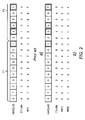
- the retransmission scheme will be described and compared in the following with a common HARQ transmission scheme as defined by 3GPP LTE (see Figure 2 a) ).
- the HARQ process ID HARQ-ID in a number range from 0 to 7 for an initial transmission or a retransmission is explicitly signalled by a retransmission process indicator RPI on a downlink link control channel (e.g.
- a TTI is also called a subframe with a time length of 1 ms.
- a radio frame of a time length of 10 ms consists of 10 subframes, which are numbered serially from #0 to #9.
- Such a serial numbering can be provided for example by applying a modulo 10 arithmetic to an endless sequence of TTI sequence numbers.
- FIG 2 a shows a first radio frame F1 with all TTIs from #0 to #9 and a second radio frame F2 with TTIs from #0 to #5.
- Figure 2 a indicates each of 16 TTis by a rectangle.
- TTI sequence numbers TTI-SN are given below the rectangles.
- the HARQ process IDs HARQ-ID are given within the rectangles.
- Initial transmissions are shown as not hatched rectangles and retransmissions for previous initial transmissions are shown as hatched rectangles.
- TTI sequence number TTI-SN #9 of the first radio frame F1 for a second HARQ process ID #1 in TTI sequence number TTI-SN #1 of the second radio frame F2 for a fourth HARQ process ID #3, in TTI sequence number TTI-SN #2 of the second radio frame F2 for a fifth HARQ process ID #4 and in TTI sequence number TTI-SN #5 of the second radio frame F2 for an eighth HARQ process ID #7.
- TTI sequence number TTI-SN #8 of the first radio frame F1 and the TTI sequence numbers TTI-SN #0, #3 and #4 of the second radio frame F2 further initial transmissions are provided from the eNodeB to the UE with HARQ process IDs #0, #2, #5 and #6.
- HARQ process IDs #0, #2, #5 and #6 Whether a transmission for a specific HARQ process ID is an initial transmission or a retransmission is indicated from the eNodeB to the UE with a further control signalling bit, which is a so-called new data indicator (not shown in Figure 2 a) for simplification).
- the present invention provides an improved method for signalling a retransmission process indicator such as the HARQ process ID applied in 3GPP LTE based on following general principle:
- the retransmission process indicator RPI for an initial transmission or a retransmission may be given regarding Figure 2 b) in binary notation RPI 1-3 with 3 bits and may be split into a first integral part RPI 1 1-2 for the two most significant bits by setting the least significant bit to "0" and a second integral part RPI 2 3 for the least significant bit by setting the two most significant bits to "0" by using for example following equation:
- RPI 1 - 3 RPI ⁇ 1 1 - 2 + RPI ⁇ 2 3
- the first and the second integral parts may be further reduced or compressed by deleting the corresponding set zero bit(s).
- the first integral part RPI1 may be transmitted as a whole from the base station BS to the mobile station MS.
- the first integral part RPI1 may be further split into two or more than two first integral sub-parts and the two or more than two first integral sub-parts may be transmitted separately from the base station BS to the mobile station MS.
- the second integral part RPI2 may be provided from the base station BS to the mobile station MS not by an explicit transmission of the second integral part RPI2 but by a correlation to a radio resource parameter that is used for the initial transmission or the retransmission.
- the second integral part RPI2 may be further split into two or more than two second integral sub-parts and the two or more than two second integral sub-parts may be provided from the base station BS to the mobile station MS by two or more correlations to two or more radio resource parameters that are used for the initial transmission or the retransmission.
- the radio resource parameter or the two or more radio resource parameters may belong to a transmission of the first integral part or the two or more than two first integral sub-parts and/or may belong to the initial transmission or the retransmission itself.
- the correlation may be based for example on a mapping table between the information in the second integral part RPI2 and a range of the radio resource parameter.
- the mapping table may be stored at the base station BS and the mobile station MS.
- the radio resource parameter is a time parameter and the time parameter is a sub-frame such as a TTI of the radio frames F1, F2. Even numbered TTIs (#0, #2, #4, #6, #8) are allocated to a first bit state "0" and odd numbered TTIs (#1, #3, #5, #7, #9) are allocated to a second bit state "1".
- Table 1 a decimal and a binary notation of the HARQ process ID HARQ-ID are shown.
- the binary notation of the HARQ process ID HARQ-ID is transmitted as the retransmission process indicator RPI from the eNodeB to the UE.
- mapping table 2 the binary version of the retransmission process indicator RPI is split exemplarily into the first integral part RPI1 denoted as a first retransmission process indicator in the following and the second integral part RPI2 denoted as a second retransmission process indicator in the following.
- the first retransmission process indicator RPI1 contains the most significant bit and a middle bit of the binary version of the retransmission process indicator RPI and the second retransmission process indicator RPI2 contains the least significant bit of the binary version of the retransmission process indicator RPI.
- the mapping between even and odd numbered TTIs and bit states "0" and "1" is shown in columns 3 and 4 of mapping Table 2.
- the bit states "0" and "1" of the second retransmission process indicator RPI2 are interpreted as a least significant bit of the retransmission process indicator RPI.
- the transmission of the first retransmission process indicator RPI1 requires one bit less than the transmission of the overall retransmission process indicator RPI.
- HARQ-ID decimal HARQ-ID binary RPI 0 000 1 001 2 010 3 011 4 100 5 101 6 110 7 111 Mapping table 2 HARQ-ID decimal RPI1 binary RPI2 binary TTI-SN 0 00 0 0 1 00 1 1 2 01 0 2 3 01 1 3 4 10 0 4 5 10 1 5 6 11 0 6 7 11 1 7
- the state of the second retransmission process indicator RPI2 only depends on the TTI sequence number TTI-SN.
- the mapping of the TTI sequence numbers TTI-SN to the states of the second retransmission process indicator RPI2 can be obtained for example by applying a modulo 2 arithmetic to the TTI sequence numbers TTI-SN and by using the remainder of the modulo 2 arithmetic as the state of the second retransmission process indicator RPI2.
- the bit states "0" and "1" of the second retransmission process indicator RPI2 may be interpreted as a most significant bit of the retransmission process indicator RPI, which is shown in mapping table 3.
- a sequence of HARQ process IDs HARQ-ID is changed from a serial numbering (see Table 2) to following sequence: #0, #4, #1, #5, #2, #6, #3, #7.
- the mobile station MS which receives the initial transmission or the retransmission and the first retransmission process indicator RPI1 obtains the information of the second retransmission process indicator RPI2 by applying the mapping table 2 or 3 to the TTI sequence numbers TTI-SN, which are known from a position of a TTI within the radio frame F1, F2.
- the mobile station MS combines the first retransmission process indicator RPI1 and the second retransmission process indicator RPI2 to determine the overall retransmission process indicator RPI for the initial transmission or for the retransmission.
- the mobile station MS adds the second retransmission process indicator RP12 as the least significant bit to the bits of the first retransmission process indicator RPI1
- the mobile station MS adds the second retransmission process indicator RPI2 as the most significant bit to the bits of the first retransmission process indicator RPI1.
- an initial transmission, a retransmission for the initial transmission and if required further retransmissions for the initial transmission may be allocated to a same state such as the bit state "0" or the bit state "1".
- the initial transmission, the retransmission for the initial transmission and if required the further retransmissions for the initial transmission may be allocated alternating to the first one of two states and to the second one of the two states.
- the number of simultaneous HARQ processes is 8
- the number of different versions of the first retransmission process indicator RPI1 is 4
- the number of different states for the second retransmission process indicator is 2.
- N 2 m ⁇ s with:
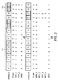
- a number of HARQ process IDs HARQ-ID is increased from 8 to 16 (not all HARQ process IDs HARQ-ID are shown in Figure 3 a) and 3 b ) for simplification) in comparison to Figure 2 a) and 2 b ).
- initial transmissions are performed during TTI sequence numbers TTI-SN #0 to #9 of the first radio frame F1 and during TTI sequence numbers TTI-SN #2 and #3 of the second radio frame F2 for HARQ process IDs HARQ-ID #0 to #11.
- a retransmission may be performed for the HARQ process ID HARQ-ID #0 by combining further redundancy information for the HARQ process ID HARQ-ID #0 with a new initial transmission for the HARQ process ID HARQ-ID #2.
- Such a combination of a retransmission with a new initial transmission is described for example in EP 2131518 A2 or EP 2178239 A2 .
- a retransmission may be performed by combining further redundancy information of the HARQ process IDs HARQ-ID #0 and #2, which are combined or superimposed by a method such as described for example in US 2010/0061287 A1 for a binary XOR addition or modulo 2 addition of three or more packets.
- a retransmission may be performed either for one of the HARQ process IDs by applying a combination of further redundancy information of one of the two respective HARQ process IDs with a new initial transmission of the further one of the two respective HARQ process IDs or a retransmission may be performed for both HARQ process IDs by applying a combination of further redundancy information for both HARQ processes.
- the combination and transmission of two HARQ processes are executed during an odd or even TTI sequence number TTI-SN in such a way, that initial transmissions of both HARQ process IDs HARQ-ID belong to TTI sequence numbers TTI-SN of a same state.
- the initial transmissions for HARQ process IDs #0, #2 are performed by TTI sequence numbers TTI-SN #0 and #2, which are both even sequence numbers.
- the retransmission for one or both of the HARQ process IDs #0, #2 based on a combination of further redundancy information for one HARQ process ID and new data of a further initial transmission for the other HARQ process ID or based on a combination of further redundancy information for both HARQ process IDs is applied by the TTI sequence number TTI-SN #0 of the second radio frame F2, which is also an even sequence number.
- mapping table 4 The mapping between the TTI sequence numbers TTI-SN, a first retransmission process indicator RPI1_1 and the second retransmission process indicator RPI2 is shown by following mapping table 4: Mapping table 4 HARQ-ID decimal RPI1_1 decimal RPI1_1 binary RPI2 binary TTI-SN 0 0 000 0 0 1 0 000 1 1 2 1 001 0 2 3 1 001 1 3 4 2 010 0 4 5 2 010 1 5 6 3 011 0 6 7 3 011 1 7 8 4 100 0 8 9 4 100 1 9 10 5 101 0 0 11 5 101 1 1 ⁇ ⁇ ⁇ ⁇ 15 7 111 1 7
- the first retransmission process indicator RPI1_1 is shown in Figure 3 a) in a decimal notation.
- the mapping table 4 shows the corresponding binary notation.
- the decimal HARQ process ID HARQ-ID is equal to a summation of the bits of the binary version of the first retransmission process indicator RPI1_1 and the bit of the second retransmission process indicator RPI2 as a least significant bit. If a retransmission is performed by a combination of two HARQ processes, a further first retransmission process indicator RPI1_2 needs to be transmitted from the base station BS to the mobile station MS for example on a control channel or by a so-called in-band signalling, which means, that the further first retransmission process indicator RPI1_2 may be transmitted together with the radio transmission data for example on a same user data channel.
- the second retransmission process indicator RPI2 can also be used and is also valid for the further first retransmission process indicator RPI1_2.
- the second retransmission process indicator RPI2 which is deduced by the mobile station MS from the mapping table 4, can be applied also for an identification of a second HARQ process ID by a summation of the received bits of the binary version of the further first retransmission process indicator RPI1_2 and the bit of the second retransmission process indicator RPI2 for example as a least significant bit as shown in mapping table 4.
- the method described according to Figure 3 a) is extended to combination of four HARQ processes as shown in Figure 3 b) .
- initial transmissions are performed during TTI sequence numbers TTI-SN #0 to #9 of the first radio frame F1 and during TTI sequence numbers TTI-SN #0, #1, #4 and #5 of the second radio frame F2 for HARQ process IDs HARQ-ID #0 to #13.
- TTI sequence number TTI-SN #2 of the second radio frame F2 a retransmission may be performed for a combination such as a modulo-2 addition of HARQ process IDs #0, #2, #4 and #6. The combination may be based for example on a combination of three retransmissions for HARQ process IDs #0, #2 and #4 and of one new initial transmission for HARQ process ID #6.
- Such a combination of several retransmissions with a new initial transmission is similar to a method as described in EP 2131518 A2 or EP 2178239 A2 for a simple combination of two HARQ processes.
- a retransmission may be performed for redundancy versions of the HARQ process IDs HARQ-ID #0, #2, #4 and # 6 which are combined by a method such as described for example in US 2010/0061287 A1 .
- a retransmission may be performed either by applying a similar method as described in EP 2131518 A2 or EP 2178239 A2 with at least one new initial transmission or by applying a similar method as described in US 2010/0061287 A1 with a combination of only redundancy versions of previous initial transmissions.
- the combination of four HARQ processes are executed in such a way, that all four HARQ process IDs HARQ-ID belong to TTI sequence numbers TTI-SN, which are either both odd or both even sequence numbers.
- the HARQ process IDs #0, #2, #4, #6 of the TTI sequence number TTI-SN #2 of the second radio frame F2 belong to the TTI sequence numbers TTI-SN #0, #2, #4, #6, which are all even sequence numbers.
- the mapping table 4 as described above may also be used for the mapping between the TTI sequence numbers TTI-SN and the second retransmission process indicator RPI2 regarding the embodiment of Figure 3b ).
- the second retransmission process indicator RPI2 which is deduced by the mobile station MS from the mapping table 4, can be applied also for an identification of the remaining three HARQ process IDs of a combination by a summation of the received bits of the binary version of the further first retransmission process indicators RPI1_2, RPI1_3, RPI1_4 and the bit of the second retransmission process indicator RPI2 for example as a least significant bit as shown in mapping table 4.
- the number of the steps for performing the method MET1 is not critical, and as can be understood by those skilled in the art, that the number of the steps and the order of the steps may vary without departing from the scope of the invention.
- VoIP Voice of Internet Protocol
- a similar downlink method may be performed between the base station BS and the relay station RS and/or between the relay station RS and the mobile station MS.
- a similar method may be performed for an uplink transmission of uplink user data from the mobile station MS to the base station BS.
- the relay station RS is used between the mobile station MS and the base station BS, a similar uplink method may be performed between the mobile station MS and the relay station RS and/or between the relay station RS and the base station BS.
- the method MET1 is exemplarily described with respect to Figure 2 b) and Figure 3a ).
- a mapping is predefined at the base station BS between a first state of the second retransmission process indicator RPI2 (state "0") and a first range of said radio resource parameter (TTI sequence numbers TTI-SN #0, #2, #4, #6, #8) for transmitting radio transmission data RTD and between a second state of the retransmission process indicator RPI2 (state "1") and a second range of the radio resource parameter (TTI sequence numbers TTI-SN #1, #3, #5, #7, #9) for transmitting the radio transmission data RTD.
- the second retransmission process indicator RPI2 is mapped to the transmission of the radio transmission data RTD.
- the second retransmission process indicator RPI2 may be alternatively mapped to the transmission of the first retransmission process indicator RPI1.
- the mapping is also predefined at the mobile station MS between the first state of the second retransmission process indicator RPI2 (state "0") and the first range of said radio resource parameter (TTI sequence numbers TTI-SN #0, #2, #4, #6, #8) and between the second state of the retransmission process indicator RPI2 (state "1") and the second range of the radio resource parameter (TRI sequence numbers TTI-SN #1, #3, #5, #7, #9).
- the base station BS transmits for example via a control channel by applying an asynchronous HARQ method the first retransmission process indicator RPI1 (see Figure 2 b) ) for a HARQ process ID HARQ-ID #2 for the first radio frame F1 and a new data indicator NDI for example set to state "1" for a next initial transmission of the radio transmission data RTD to the mobile station MS, which receives the first retransmission process indicator RPI1 or RPI1_1 in a further step M1/4.
- the new data indicator NDI is set to state "0".
- a new initial transmission may be indicated by a change of state of the new data indicator NDI from state "0" to state "1” or vice versa, and a retransmission by no change of state of the NDI, when comparing the state of the received new data indicator NDI to the previous state of new data indicator NDI received for the same HARQ process number.
- the first retransmission process indicator RPI1 may be split by the base station BS into two or more than two parts and the base station BS performs separate transmissions to the mobile station MS for the two or more than two parts.
- the base station BS may split the first retransmission process indicator RPI1 into two parts and the base station BS transmits a first part of the two parts via the step M1 /3 and transmits a second part of the two parts for example via in-band signaling.
- the mobile station MS which receives the two or more than two parts performs a combination of the two or more than two parts, which is an inverse process to the splitting performed by the base station BS, to obtain the first retransmission process indicator RPI1.
- the base station BS transmits the first retransmission process indicator RPI1_1 for a HARQ process ID HARQ-ID #0 of the second radio frame F2 and a new data indicator NDI set to state "0" for a next retransmission of radio transmission data RTD to the mobile station MS.
- the first retransmission process indicator RPI1 or RPI1_1 and new data indicator NDI or NDI_1 may be transmitted for example as part of a scheduling grant such as applied in 3GPP LTE.
- the radio transmission data RTD are located in a same TTI as applied for the transmission of the scheduling grant.
- the scheduling grant is transmitted two time slots ahead to the transmission of the radio transmission data RTD, so that the mobile station MS implicitly knows, if it receives a scheduling grant, that the radio transmission data RTD will be received after two further time slots.
- the mobile station MS may store the received first retransmission process indicator RPI1 or RPI1_1 and the received new data indicator NDI or NDI_1 for later processing.
- the base station BS transmits in a further step M1/6 the further first retransmission process indicator RPI1_2 for a HARQ process ID HARQ-ID #2 of the second radio frame F2 and a further new data indicator NDI_2 set to state "0" for the next retransmission of the radio transmission data RTD to the mobile station MS, which receives the further first retransmission process indicator RPI1_2 and the further new data indicator NDI_2 in a next step M1/7.
- the mobile station MS may store the received further first retransmission process indicator RPI1_2 and the received further new data indicator NDI_2 for later processing.
- the base station BS transmits the radio transmission data RTD to the mobile station MS, which receives the radio transmission data RTD in a further step M1/10.
- the base station BS applies for the transmission of the radio transmission data RTD a TTI sequence number TTI-SN, which corresponds to this implicit or explicit signaling.
- the base station BS provides implicitly the second retransmission process indicator RPI2 to the mobile station MS, because the radio transmission data RTD are transmitted with a TTI sequence number TTI-SN #2 (see Figure 2 a) ) or with a TTI sequence number TTI-SN #0 (see Figure 3 a) ), which are both even numbers and therefore both mapped to the state "0" of the second retransmission process indicator RPI2.
- the mobile station MS identifies the HARQ process ID HARQ-ID of the initial transmission (see Figure 2 b) or of the retransmission (see Figure 3 a) ) based on the received first retransmission process indicator RPI1 or RPI1_1 and based on the provided second retransmission process indicator RPI2. Therefore, the mobile station MS derives the TTI sequence number based on an application of a conventional downlink frame synchronization algorithm.
- predefined synchronization signals are transmitted within predefined time-frequency positions of each radio frame. A time location of these synchronization signals is detected by the mobile station MS, e.g. by computing the cross-correlation of the predefined sequences with the received sequences.
- step M1/11 the mobile station MS deduces the second retransmission process indicator RPI2 based on the TTI sequence number TTI-SN #2 (see Figure 2 a) ) or the TTI sequence number TTI-SN #0 (see Figure 3 a) ), which have been applied for the transmission of the radio transmission data RTD and based on the predefined mapping.
- step M1/12 the mobile station MS may store the deduced second retransmission process indicator RPI2 for later processing in step M1/13.
- the mobile station MS determines retransmission process indicator RPI for the HARQ process ID HARQ-ID #2 (see Figure 2 b) ) or #0 (see Figure 3 a) ) from the received first retransmission process indicator RPI1 (see Figure 2 b) ) or RPI1_1 (see Figure 3 a) ) and from the deduced second retransmission process indicator RPI2.
- a determination may be for example based on generating a bit sequence of the bits of the first retransmission process indicator RPI1 and of the bit of the second retransmission process indicator RPI2 as described above and based on a following interpretation of the bit sequence.
- the mobile station MS performs for example an algorithm, which is inverse to the algorithm, which is described with respect to equation (1).
- the mobile station MS further identifies in a next step M1 /14 the further retransmission process indicator RPI for the HARQ process ID HARQ-ID #2 by determining the further retransmission process indicator RPI for the HARQ process ID HARQ-ID #2 from the received further first retransmission process indicator RPI1_2 and from the deduced second retransmission process indicator RPI2 by generating a further bit sequence similar to the method as described above.
- the mobile station MS performs a conventional data recovery for the received radio transmission data RTD for an initial transmission or a retransmission of a single HARQ process, for example, by a maximal ratio combining of the sampled receive signals of the initial transmission and retransmission(s) of the initial transmission prior to demodulation and decoding such as described for example in Chapter 3.2 of D. Tse and P. Viswanath, "Fundamentals of Wireless Communication,” Cambridge University Press 2005, or alternatively by adding soft bits, e.g.
- the mobile station MS may transmit an acknowledgement ACK, if the mobile station MS has successfully recovered the received radio transmission data RTD or transmits a negative acknowledgement NACK, if the mobile station MS has not successfully recovered the received radio transmission data RTD.
- the base station BS receives the acknowledgement ACK or the negative acknowledgement NACK.
- the mobile station MS may transmit a first acknowledgement ACK1, if the mobile station MS has successfully recovered the received radio transmission data RTD of the HARQ process ID HARQ-ID #0 or transmits a first negative acknowledgement NACK1, if the mobile station MS has not successfully recovered the received radio transmission data RTD of the HARQ process ID HARQ-ID #0.
- the mobile station MS may transmit a second acknowledgement ACK2, if the mobile station MS has successfully recovered the received radio transmission data RTD of the HARQ process ID HARQ-ID #2 or transmits a second negative acknowledgement NACK2, if the mobile station MS has not successfully recovered the received radio transmission data RTD of the HARQ process ID HARQ-ID #2.
- the base station BS transmits a new initial transmission for the same HARQ process ID and a corresponding first retransmission process indicator RPI1 or RPI1_1 if the base station BS has received the acknowledgement ACK, ACK1 or ACK2 or the base station BS transmits a further redundancy version for the same HARQ process ID and a corresponding retransmission process indicator RPI1 or RPI1_1 if the base station BS has received the negative acknowledgement NACK, NACK1 or NACK2.
- An explicit transmission of the acknowledgement ACK, ACK1 or ACK2 is not required, if for example it is predefined at the base station BS and the mobile station MS, that the acknowledgement doesn't need to be transmitted, if the base station BS starts a timer at the point of time, when the radio transmission data RTD are transmitted and if the base station BS interprets a non-reception of the acknowledgement ACK, ACK1 or ACK2 as a successful data recovery at the mobile station MS.
- Figure 5 a shows another possibility for signalling and providing retransmission process indicators from the base station BS to the mobile station MS.
- the transmission and retransmission method is exemplarily shown for four HARQ processes with decimal HARQ process IDs HARQ-ID #0, #1, #2 and #3.
- the retransmission process indicator RPI for signalling the HARQ process ID from the base station BS to the mobile station MS is split into the first retransmission process indicator RPI1 and the second retransmission process indicator RPI2.
- the first retransmission process indicator RPI1 is transmitted via the radio link RL from the base station BS to the mobile station MS, whereas the second retransmission process indicator RPI2 is provided from the base station to the mobile station MS in a following way:
- a frequency spectrum FS of the radio link RL may be split into a first frequency block FB1 below a predefined radio frequency PRF and a second frequency block FB2 above the predefined radio frequency PRF.
- the predefined radio frequency PRF may be for example a mean radio frequency of the frequency spectrum FS.
- the second retransmission process indicator RPI2 may be mapped for example to a "0" bit state and for an initial transmission or a retransmission via the second frequency block FB2, the second retransmission process indicator RPI2 may be mapped for example to a "1" bit state.
- mapping table 5 An exemplary mapping between the bit states of the second retransmission process indicator RPI2 and the frequency blocks FB1, FB2 regarding the embodiment of Figure 5 a) is shown in mapping table 5.
- the bit state of the second retransmission process indicator RPI2 may be the most significant bit of the retransmission process indicator RPI.
- Figure 5 b shows a further embodiment for signalling and providing retransmission process indicators from the base station BS to the mobile station MS.
- the transmission and retransmission method is exemplarily shown for eight HARQ processes with decimal HARQ process IDs HARQ-ID #0 to #7 but only four HARQ processes with decimal HARQ process IDs HARQ-ID #0 to #3 are shown for simplification.
- the retransmission process indicator RPI for signalling the HARQ process ID from the base station BS to the mobile station MS is split into the first retransmission process indicator RPI1 and the second retransmission process indicator RPI2.
- the first retransmission process indicator RPI1 is transmitted via the radio link RL from the base station BS to the mobile station MS, whereas the second retransmission process indicator RPI2 is provided from the base station to the mobile station MS in a following way:
- a downlink physical resource DPR such as an 3GPP LTE downlink physical resource of the radio link RL may be split into four frequency blocks FB1, FB2, FB3, FB4.
- Each frequency block may be split into 25 resource blocks RB (see mapping table 6), for example assuming 20 MHz system bandwidth (100 RBs).
- Each resource block RB may contain 12 frequency subcarriers with a 15 kHz subcarrier spacing such as applied in 3GPP LTE.
- Each frequency block is mapped to a two bit state of the second retransmission process indicator RPI2 as shown in the mapping table 6.
- Resource coverage of radio transmission data RTD1, RTD2, RTD3 and RTD4 for each of the four HARQ process IDs HARQ-ID #0 - #3 is also shown in Figure 5 b) .
- Each of the radio transmission data RTD1, RTD2, RTD3 and RTD4 covers several resource blocks RB of the downlink physical resource DPR.
- a resource block with smallest frequency subcarriers RB_IND1, RB-IND2, RB-IND3, RB-IND4 covered by the radio transmission data RTD1, RTD2, RTD3 or RTD4 may be used for example for indicating the two bit state of the second retransmission process indicator RPI2 to the mobile station MS as the receiver of the radio transmission data RTD1, RTD2, RTD3 and RTD4.
- the two bit state of the second retransmission process indicator RPI2 may be the two least significant bits of the retransmission process indicator RPI.
- RPI ⁇ 2 RB_ IND mod s
- the states of the second retransmission process indicator RPI2 may be alternatively mapped to an indexed pool or group of at least two transmit codes such as Hadamard, DFT or Zadoff-Chu spreading codes.
- transmit codes such as Hadamard, DFT or Zadoff-Chu spreading codes.
- a first block may be mapped to a first state such as a first bit state "0" of the second retransmission process indicator RPI2 and a second block may be mapped to a second state such as a second bit state "1" of the second retransmission process indicator RPI2.
- a smallest index of two or more than two applied transmit codes may determine a state of the second retransmission process indicator RPI2 by a corresponding mapping table.
- the second retransmission process indicator RPI2 may be tagged for example to a smallest transmit code index, which is applied for a multi-code resource allocation. In 3GPP HSDPA for example 16 different transmit codes are applied within a radio cell.
- Such a mapping may be used, if for example in case of 3GPP HSDPA the base station BS transmits user data to the mobile station MS via two spreading codes and a first group of the user data is coded with the first spreading code and a second group of the user data is coded with the second spreading code.
- the second retransmission process indicator RPI2 may be split into two or more parts and for each of these parts a mapping may be predefined at the base station BS and at the mobile station MS between two or more states of this part of the second retransmission process indicator RPI2 and two or more ranges of a different radio resource parameter.
- a first mapping of a first part of the second retransmission process indicator RPI2 may be predefined between two states of the first part of the second retransmission process indicator RPI2 and even or odd TTI sequence numbers TTI-SN as described above (see for example embodiment regarding Figure 2 b) ).
- a second mapping of a second part of the second retransmission process indicator RPI2 may be predefined between two states of the second part of the second retransmission process indicator RPI2 and high or low frequency ranges as described above (see for example embodiment regarding Figure 5 a) ).
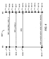
- FIG. 6 a further embodiment for signalling and providing the retransmission process indicator RPI from the base station BS to the mobile station MS is shown.
- the main difference between this embodiment and the preceding embodiments shown in Figures 2 b) , 3 a) , 3 b) , 5 a) and 5 b) is based on the fact, that the implicit indication of the second retransmission process indicator RPI2 is not provided by a radio resource parameter of the transmission of the radio transmission data RTD, RTD1, RTD2, RTD3, RTD4 but provided by a radio resource parameter of the transmission of the first retransmission process indicator RPI1.
- Figure 6 shows exemplarily four control channels CC1, CC2, CC3, CC4, which are used for transmitting the first retransmission process indicator RPI1 from the base station BS to the mobile station MS.
- a HARQ process ID HARQ-ID can be identified at the mobile station MS by a transmission of the first retransmission process indicator RPI1 and further by a control channel, which either transmits the first retransmission process indicator RPI1 or which transmits radio resource assignment information for in-band signalling of the first retransmission process indicator RPI1.
- the transmitted radio resource assignment information allows the receiving apparatus such as the mobile station MS to know, where to find control information (here the first retransmission process indicator RPI1) within resource blocks for a transmission of the radio transmission data RTD.
- mapping table 7 HARQ-ID decimal RPI1 binary RPI2 binary Control channel 0 0 0 CC1 1 0 1 CC2 2 1 0 CC3 3 1 1 CC4
- the CPU TA-CPU and the computer readable medium TA-MEM may be based for example on a digital baseband board.
- the CPU TA-CPU is foreseen for executing a computer readable program TA-PROG.
- the computer readable medium TA-MEM is foreseen for storing the computer readable program TA-PROG.
- the computer readable program TA-PROG is foreseen for executing steps of the method MET1 belonging to the transmitting apparatus TA.
- the computer readable medium TA-MEM may store one or several of the mapping tables as described above.
- the base station BS, the mobile station MS or the relay station RS may contain the transmitting apparatus TA for example as part of a transceiver.
- a CPU central processing unit
- RA-CPU central processing unit
- RA-MEM computer readable medium
- RA-OUT for providing the recovered application for example to an application such as a video client.
- Further conventional components of the receiving apparatus RA such as power supply/battery, radio receiver, demodulator, and baseband processing are not shown for simplification.
- the CPU RA-CPU and the computer readable medium RA-MEM may be based for example on a digital baseband board.
- the CPU RA-CPU is foreseen for executing a computer readable program RA-PROG.
- the computer readable medium RA-MEM is foreseen for storing the computer readable program RA-PROG.
- the computer readable program RA-PROG is foreseen for executing steps of the method MET1 belonging to the receiving apparatus RA.
- the computer readable medium RA-MEM may store one or several of the mapping tables as described above and may store the received first retransmission process indicator RPI1, the further first retransmission process indicator RPI1_2, the received further new data indicator NDI_2 and the deduced second retransmission process indicator RPI2.
- the base station BS, the mobile station MS or the relay station RS may contain the receiving apparatus RA for example as part of a transceiver.
- unit or "means for " shall be understood as functional blocks comprising circuitry that is adapted for performing a certain function, respectively.
- a "means for s.th” may as well be understood as a “means being adapted or suited for s.th.”.
- a means being adapted for performing a certain function does, hence, not imply that such means necessarily is performing said function (at a given time instant).
- the functions of the various elements of the transmitting apparatus TA shown in Figure 7 a) and of the receiving apparatus RA shown in Figure 7 b) may be provided through the use of dedicated hardware as well as the through the use of hardware capable of executing software in association with appropriate software.
- the functions may be provided by a single dedicated processor, by a single shared processor, or by a plurality of individual processors, some of which may be shared.
- processor or “controller” should not be construed to refer exclusively to hardware capable of executing software, and may implicitly include, without limitation, digital signal processor (DSP) hardware, network processor, application specific integrated circuit (ASIC), field programmable gate array (FPGA), read only memory (ROM) for storing software, random access memory (RAM), and non volatile storage. Other hardware, conventional and/or custom, may also be included.
- DSP digital signal processor
- ASIC application specific integrated circuit
- FPGA field programmable gate array
- ROM read only memory
- RAM random access memory
- non volatile storage Other hardware, conventional and/or custom, may also be included.
- any switches shown in the Figures are conceptual only. Their function may be carried out through the operation of program logic, through dedicated logic, through the interaction of program control and dedicated logic, or even manually, the particular technique being selectable by the implementer as more specifically understood from the context. It should be appreciated by those skilled in the art that any block diagrams herein represent conceptual views of illustrative circuitry embodying the principles of the invention
Landscapes
- Engineering & Computer Science (AREA)
- Signal Processing (AREA)
- Computer Networks & Wireless Communication (AREA)
- Mobile Radio Communication Systems (AREA)
- Detection And Prevention Of Errors In Transmission (AREA)
Description
- The invention relates to wireless communications and, more particularly but not exclusively, to asynchronous retransmission in a radio communication system.
- HARQ (HARQ = hybrid automatic repeat request) with chase combining or incremental redundancy is widely used in modern packet based wireless communication systems such as UMTS systems (UMTS = Universal Mobile Telecommunication Systems) or LTE systems (LTE = Long Term Evolution). HARQ is used in these systems in conjunction with adaptive modulation and coding so as to compensate for transmission errors caused by imperfect link adaptation. Imperfect link adaptation causes significant throughput degradation as compared to the theoretical limits, despite of using HARQ.
With HARQ, typically a CRC check (CRC = Cyctic Redundancy Check) is performed upon reception of a first transmission of an encoded data packet and the result of the CRC check, PASS or FAIL, is reported to the transmitter as an ACK (ACK = acknowledgement) or a NACK (NACK = Negative Acknowledgement), respectively. In case of NACK, the transmitter performs a retransmission of the data packet and soft combining of the codewords of the received first transmission and the received retransmission is performed by the receiver before the decoding. Soft combining improves error rate performance as compared to simply discarding the first transmission attempt at the receiver,
With chase combining the retransmission uses the same codeword size and same RV parameters (RV = redundancy version), i.e. puncturing patterns, as the first transmission. The retransmission of the whole codeword size of the first transmission may consume more radio link capacity than required.
With incremental redundancy only a subset of the information bits or none of the information bits of the first transmission and only parity bits are retransmitted.
In LTE for example, eight HARQ processes can be applied simultaneously. Each HARQ process is identified by a retransmission process indicator, which is called HARQ process number in case of LTE (see 3GPP Technical Specification 36.212). In addition to the retransmission process indicator a further indicator is usually reported from the transmitter to the receiver such that the receiver is able to identify, whether data received for a specific retransmission process indicator are new data for a new initial transmission or the data to be received belong to a retransmission of a former initial transmission.
InWO 2008/104099 A1 a transmitter chooses based on at least one packet parameter a partial error protection to be applied to the at least one packet. The transmitter indicates the applied partial error protection to a receiver in a way agreed between the transmitter and the receiver. The bits to be included in the partial error protection calculations are implicitly provided to the receiver by a combination of usage of certain size of transmitted data blocks and usage of a certain HARQ process. - The way of signalling HARQ processes in a radio communication system effects an allocation of radio resources for control information and affects an overall throughput for user data in the radio communication system.
It is an object of the invention to reduce an allocation of radio resources for control information in the radio communication system and to increase the overall throughput for user data in the radio communication system.
The object is achieved by a method for asynchronous retransmission in a radio communication system, The method contains the steps of splitting at a transmitting apparatus a retransmission process indicator into at least a first part and at least a second part, transmitting the at least first part of the retransmission process indicator for an initial transmission or a retransmission of radio transmission data from the transmitting apparatus to a receiving apparatus, providing the at least second part of the retransmission process indicator from the transmitting apparatus to the receiving apparatus by a mapping to a radio resource parameter that is applied for the initial transmission or the retransmission, deducing at the receiving apparatus the provided at least second part of the retransmission process indicator based on the applied radio resource parameter and based on the mapping, and determining at the receiving apparatus the retransmission process indicator from the received at least first part and the deduced at least second part. The object is further achieved by a transmitting apparatus for asynchronous retransmission in a radio communication system and by a receiving apparatus for asynchronous retransmission in a radio communication system.
The method for indicating initial transmissions or retransmissions such as HARQ process numbers from a transmitting apparatus to a receiving apparatus is based on an explicit transmission and a further implicit provision of information, which is split at the transmitting apparatus into two parts and which are merged at the receiving apparatus to obtain the whole information. For the at least first part control information is explicitly transmitted from the transmitting apparatus to the receiving apparatus. The at least second part is based on information, which is not explicitly transmitted but which can be deduced from a radio resource parameter, which is applied for the HARQ process.
According to three alternatives, the radio resource parameter is a radio resource parameter for transmitting the initial transmission or the retransmission or is a radio resource parameter for transmitting the at least first part of the retransmission process indicator or is a radio resource parameter for transmitting an indication for a radio resource, which contains the at least first part of the retransmission process indicator. The radio resource parameter may be for example a time parameter, a frequency parameter or a coding parameter.
The method offers a first benefit of not requiring increasing a number of signalling bits for the retransmission process indicator, if a number of HARQ processes will be increased in an existing radio communication system. A higher number of HARQ processes may be required for example, if resource coverage of redundancy information of a single retransmission is decreased so that two or more retransmissions fit into a radio resource of a conventional retransmission and if a continuous scheduling to a single receiving apparatus shall be guaranteed.
According to a further use case, multi stream multiplexing may be applied by a MIMO transmission (MIMO = multiple input multiple output), if the transmitter apparatus applies two or more antenna elements for the transmission of radio transmission data such as user data or control data to the receiving apparatus. In such a case, a number of HARQ processes may increase linearly with a number of simultaneous data streams from the transmitting apparatus to the receiving apparatus and/or to further receiving apparatuses resulting in a large number of HARQ processes, which require an adequate identification at the receiving apparatus and/or the further receiving apparatuses. By applying the present invention, an increase of the amount of radio resources for signalling the additional HARQ processes can be avoided or at least can be reduced. By applying multi stream multiplexing an initial transmission may be performed on a first stream and a retransmission may be performed on a second stream; such retransmission can be enabled if a so-called HARQ process ID is signalled together with a stream ID that relates to pre-coding information, such as the "Transport block to codeword swap flag" inDCI Format 2 of LTE Rel8 (3GPP Technical Specification 36.212). Multiple (e.g. reduced-size) retransmissions can be performed on a same stream within a same TTI (TTI = transmission time interval), also when (part of) initial transmissions were performed on another stream or on multiple streams; such multiple retransmissions can be enabled in that for each retransmission the HARQ process ID is signalled together with a respective stream ID that relates to pre-coding information. Further redundancy information for a retransmission of data of previous initial transmissions via one, two or more than two streams may be multiplexed to a single data packet within a single TTI and this data packet is transmitted from the transmitting apparatus to the receiving apparatus. In case of CoMP transmission (CoMP = Cooperative Multi Point), the different streams can be transmitted from different cells or sites, e.g. via different base stations or via different remote radio heads; this can be enabled in that the HARQ process IDs are defined on a per user basis or on a per mobile station basis, irrespective of a base station site or cell ID etc.
The method offers a second benefit of reducing a number of signalling bits for the retransmission process indicator, if a number HARQ processes is kept constant in an existing radio communication system.
The method provides a third benefit of designing a new radio communication system with fewer signalling bits for transmitting the retransmission process indicators.
According to a preferred embodiment, the method contains the steps of predefining at the transmitting apparatus and at the receiving apparatus the mapping between a first state of the at least second part of the retransmission process indicator and a first range of the radio resource parameter and between at least a second state of the at least second part of the retransmission process indicator and at least a second range of the radio resource parameter, and the determining step may contain the sub-steps of deducing at the receiving apparatus the at least second part of the retransmission process indicator based on the mapping and based on the first range or the at least second range of the received radio resource parameter, and determining at the receiving apparatus the retransmission process indicator from the received at least first part of the retransmission process indicator and from the deduced at least second part of the retransmission process indicator.
According to a first alternative embodiment, the time parameter is a time period of at least two transmit time intervals, the at least two transmit time intervals are numbered serially, even numbered transmit time intervals of the at least two transmit time intervals are allocated to a first one of the at least two states and odd numbered transmit time intervals of the at least two transmit time intervals are allocated to a second one of the at least two states.
According to a second alternative embodiment, the frequency parameter is a frequency range of at least two transmit frequency sub-ranges, a first one of the at least two transmit frequency sub-ranges is allocated to a first one of the at least two states and a second one of the at least two transmit frequency sub-ranges is allocated to a second one of the at least two states.
According to a third alternative embodiment, the coding parameter is a group of at least two transmit codes, a first one of the at least two transmit codes is allocated to a first one of the at least two states and a second one of the at least two transmit codes is allocated to a second one of the at least two states. According to a fourth alternative embodiment, the radio resource parameter is a frequency location for transmitting the initial transmission or the retransmission or for transmitting the at least first part of the retransmission process indicator or is a radio resource parameter for indicating a radio resource, which contains the at least first part of the retransmission process indicator.
In a further improved embodiment, the method further contains the steps of transmitting at least a first part of at least one further retransmission process indicator for at least one further initial transmission or at least one further retransmission of radio transmission data from the transmitting apparatus to the receiving apparatus and determining at the receiving apparatus the at least one further initial transmission or the at least one further retransmission based on the received at least first part of the at least one further retransmission process indicator and based on the provided at least second part of the retransmission process indicator. The further improved embodiment provides the advantage of avoiding a transmission of two or more full size retransmission process indicators. Thereby, the signaling overhead can be further decreased for example for a retransmission of combined HARQ processes such as described inEP 2 131 518 A2EP 2178239 A2 . The further improved embodiment may be applied, if for example a retransmission of a former initial transmission and a new initial transmission are superimposed for example by a modulo-2 addition to a combination by the transmitting apparatus and the combination is transmitted from the transmitting apparatus to the receiving apparatus such as described for example inEP 2131518 A2 orEP 2178239 A2 . In such a case, e.g. a first part of the further retransmission process indicator for the further retransmission of the further former initial transmission is explicitly signaled to the receiving apparatus and a second part of the further retransmission process indicator is implicitly signaled to the receiving apparatus based on the applied one of the at least two states of the parameter and based on the explicitly signaled first part of the further retransmission process indicator.
According to further alternative embodiments, the initial transmission, a retransmission for the initial transmission and further retransmissions for the initial transmission are allocated to a same state or are allocated alternating to the first one of the at least two states and to the second one of said at least two states.
Preferably, a number of retransmission processes may be equal to a multiplication of a number of values applied for the at least one first part of the retransmission process indicator by a number of the applied two or more than two states.
More preferably, the number N of retransmission processes, the number s of the at least two states, and the number m of bits for transmitting the at least first part of the retransmission process indicator may fulfill the equation N = 2m × s.
In further preferred alternative embodiments, the number of retransmission processes between the transmitting apparatus and the receiving apparatus may be given as a binary number and the one of the at least two states may be interpreted as at least one least significant bit or as at least one most significant bit for determining the retransmission process indicator.
Further advantageous features of the invention are defined and are described in the following detailed description of the invention. - The embodiments of the invention will become apparent in the following detailed description and will be illustrated by accompanying figures given by way of non-limiting illustrations.
-
Figure 1 shows a block diagram of an exemplary radio communication network for performing an asynchronous retransmission method. -
Figure 2 a) shows a conventional HARQ protocol as applied in 3GPP LTE andFigure 2 b) shows a method for signalling and providing retransmission process indicators according to a first embodiment of the invention. -
Figures 3 a) and b) show further methods for signalling and providing retransmission process indicators in accordance to two further embodiments of the invention. -
Figure 4 shows a flow diagram of a method according to the embodiments of the invention. -
Figures 5 a) and b) show even further methods for signalling and providing retransmission process indicators in accordance to two even further embodiments of the invention. -
Figure 6 shows a further embodiment for signalling and providing retransmission process indicators. -
Figures 7 a) and b) show block diagrams of a transmitting apparatus and a receiving apparatus according to the embodiments of the invention. -
Figure 1 shows a radio communication system RCS comprising a radio access network RAN. The core network of the radio communication system RCS and connections of the radio communication system RCS to further radio communication systems, to the Internet or to fixed line communications systems are not shown for simplification.
The radio communication system RCS may be for example a 3GPP LTE radio communication network using OFDM (OFDM = Orthogonal Frequency Division Multiplexing). In further alternatives, the radio communication system RCS may for example a 3GPP UMTS/HSPA radio communication network (UMTS = Universal Mobile Telecommunication Systems, HSPA = High Speed Packet Access), a WIMAX radio communication network (WiMAX = Worldwide Interoperability for Microwave Access) based for example on the IEEE 802.16d standard (IEEE = Institute of Electrical and Electronics Engineers), or a WLAN (WLAN) based for example on the IEEE 802.11 g standard.
The radio access network RAN comprises a base station BS. The term "base station" may be considered synonymous to and/or referred to as a base transceiver station, base station, Node B, enhanced Node B, access point etc. and may describe equipment that provides connectivity via a radio link between the radio communication system RCS and one or more mobile stations.
Further base stations of the radio access network RAN, further network nodes of the radio communication system RCS, connections between base stations, and connections between base stations and further network nodes of the radio communication system RCS are not shown for simplification.
The base station BS provides wireless coverage for a specific geographical area being a radio cell RC. The term "radio cell" considered synonymous to and/or referred to as radio cell, cell, radio sector, sector etc.
A mobile station MS is located within a wireless coverage area of the radio cell RC.
The term "mobile station" may be considered synonymous to, and may hereafter be occasionally referred to, as a mobile unit, mobile station, mobile user, access terminal, user equipment, subscriber, user, remote station etc. The mobile station MS may be for example a cellular telephone, a portable computer, a pocket computer, a hand-held computer, a personal digital assistant, a USB flash drive with a radio interface or a car-mounted mobile device.
The base station BS communicates with the mobile station MS via a radio link RL. The base station BS and the mobile station MS may use on a downlink from the base station BS to the mobile station MS a retransmission scheme such as a HARQ transmission scheme and/or may use on an uplink from the mobile station MS to the base station BS a further retransmission scheme. The retransmission scheme and/or the further retransmission scheme may be asynchronous, which means that there is no time period predefined for the time between an initial transmission and a retransmission for the initial transmission.
In an alternative, the radio cell RC may further comprise a relay station RS (indicated by dotted lines inFigure 1 ). In such a case, the base station BS may communicate with the relay station RS via a first radio link RL1 and the relay station RS may communicate with the mobile station MS via a second radio link RL2 and on one or both radio links RL1, RL2 a HARQ transmission scheme may be applied.
In a further alternative, the base station BS may communicate with the relay station RS via the first radio link RL1, the relay station RS may communicate with the mobile station MS via the second radio link RL2, and the base station BS may communicate with the mobile station MS via the radio link RL for transmitting for example signalling information between the base station BS and the mobile station MS. In an even further alternative, a communication between the base station BS and the mobile station MS is relayed by more than one relay station.
The retransmission scheme will be described and compared in the following with a common HARQ transmission scheme as defined by 3GPP LTE (seeFigure 2 a) ). In 3GPP LTE the HARQ transmission scheme in downlink direction from a so-called eNodeB (base station term in LTE) to a UE (UE = user equipment) applies eight simultaneous HARQ processes per UE. This means, that each initial transmission or each retransmission uses one of eight retransmission process indicators. The HARQ process ID HARQ-ID in a number range from 0 to 7 for an initial transmission or a retransmission is explicitly signalled by a retransmission process indicator RPI on a downlink link control channel (e.g. the Physical Downlink Control Channel PDCCH in case of LTE, cf. 3GPP Technical Specification 36.211) by 3 bits in advance to the initial transmission or the retransmission or within the same TTI as applied for the initial transmission or the retransmission. In 3GPP LTE a TTI is also called a subframe with a time length of 1 ms. A radio frame of a time length of 10 ms consists of 10 subframes, which are numbered serially from #0 to #9. Such a serial numbering can be provided for example by applying a modulo 10 arithmetic to an endless sequence of TTI sequence numbers.Figure 2 a) shows a first radio frame F1 with all TTIs from #0 to #9 and a second radio frame F2 with TTIs from #0 to #5.
A HARQ RTT (RTT = round-trip time) is equal to 8 time slots, a.k.a. TTIs, e.g. an initial packet transmission with HARQprocess ID # 0 takes place inTTI # 0, ACK/NACK on uplink from the UE to the eNodeB arrives inTTI # 4 and in case of ACK a new initial transmission for HARQprocess ID # 0 can be performed in TTI #8 (seeFigure 2 a) ) or in any later TTI (within a configurable window of for example 50 TTIs).Figure 2 a) indicates each of 16 TTis by a rectangle. TTI sequence numbers TTI-SN are given below the rectangles. The HARQ process IDs HARQ-ID are given within the rectangles. Initial transmissions are shown as not hatched rectangles and retransmissions for previous initial transmissions are shown as hatched rectangles. This means that for the eight initial transmissions during TTI sequence numbers TTI-SN 0 to 7 retransmissions are required in TTI sequence number TTI-SN # 9 of the first radio frame F1 for a second HARQprocess ID # 1, in TTI sequence number TTI-SN # 1 of the second radio frame F2 for a fourth HARQprocess ID # 3, in TTI sequence number TTI-SN # 2 of the second radio frame F2 for a fifth HARQprocess ID # 4 and in TTI sequence number TTI-SN # 5 of the second radio frame F2 for an eighth HARQprocess ID # 7. For the TTI sequence number TTI-SN # 8 of the first radio frame F1 and the TTI sequence numbers TTI-SN # 0, #3 and #4 of the second radio frame F2 further initial transmissions are provided from the eNodeB to the UE with HARQprocess IDs # 0, #2, #5 and #6. Whether a transmission for a specific HARQ process ID is an initial transmission or a retransmission is indicated from the eNodeB to the UE with a further control signalling bit, which is a so-called new data indicator (not shown inFigure 2 a) for simplification).
The present invention provides an improved method for signalling a retransmission process indicator such as the HARQ process ID applied in 3GPP LTE based on following general principle:
The retransmission process indicator RPI for an initial transmission or a retransmission may be given regardingFigure 2 b) in binary notation RPI 1-3 with 3 bits and may be split into a first integral part RPI11-2 for the two most significant bits by setting the least significant bit to "0" and a second integral part RPI23 for the least significant bit by setting the two most significant bits to "0" by using for example following equation:
For example RPI 1-3 = 101 is split into RPI11-2 =100 and RPI23 = 001
In a further step the first and the second integral parts may be further reduced or compressed by deleting the corresponding set zero bit(s). - According to the above example this means that RPI11-2 and RPI23 are further reduced to RPI11-2=10 and RPI23 =1.
The first integral part RPI1 may be transmitted as a whole from the base station BS to the mobile station MS. Alternatively, the first integral part RPI1 may be further split into two or more than two first integral sub-parts and the two or more than two first integral sub-parts may be transmitted separately from the base station BS to the mobile station MS.
Similarly, the second integral part RPI2 may be provided from the base station BS to the mobile station MS not by an explicit transmission of the second integral part RPI2 but by a correlation to a radio resource parameter that is used for the initial transmission or the retransmission. Alternatively, the second integral part RPI2 may be further split into two or more than two second integral sub-parts and the two or more than two second integral sub-parts may be provided from the base station BS to the mobile station MS by two or more correlations to two or more radio resource parameters that are used for the initial transmission or the retransmission. The radio resource parameter or the two or more radio resource parameters may belong to a transmission of the first integral part or the two or more than two first integral sub-parts and/or may belong to the initial transmission or the retransmission itself. The correlation may be based for example on a mapping table between the information in the second integral part RPI2 and a range of the radio resource parameter. The mapping table may be stored at the base station BS and the mobile station MS. According toFigure 2 b) the radio resource parameter is a time parameter and the time parameter is a sub-frame such as a TTI of the radio frames F1, F2. Even numbered TTIs (#0, #2, #4, #6, #8) are allocated to a first bit state "0" and odd numbered TTIs (#1, #3, #5, #7, #9) are allocated to a second bit state "1". In following Table 1 a decimal and a binary notation of the HARQ process ID HARQ-ID are shown. In a common LTE HARQ mechanism, the binary notation of the HARQ process ID HARQ-ID is transmitted as the retransmission process indicator RPI from the eNodeB to the UE. In following mapping table 2 the binary version of the retransmission process indicator RPI is split exemplarily into the first integral part RPI1 denoted as a first retransmission process indicator in the following and the second integral part RPI2 denoted as a second retransmission process indicator in the following. The first retransmission process indicator RPI1 contains the most significant bit and a middle bit of the binary version of the retransmission process indicator RPI and the second retransmission process indicator RPI2 contains the least significant bit of the binary version of the retransmission process indicator RPI. The mapping between even and odd numbered TTIs and bit states "0" and "1" is shown incolumns Figure 2 b) and the mapping table 2 the bit states "0" and "1" of the second retransmission process indicator RPI2 are interpreted as a least significant bit of the retransmission process indicator RPI. In comparison to Table 1, the transmission of the first retransmission process indicator RPI1 requires one bit less than the transmission of the overall retransmission process indicator RPI.Table 1 HARQ-ID decimal HARQ-ID binary, RPI 0 000 1 001 2 010 3 011 4 100 5 101 6 110 7 111 Mapping table 2 HARQ-ID decimal RPI1 binary RPI2 binary TTI- SN 0 00 0 0 1 00 1 1 2 01 0 2 3 01 1 3 4 10 0 4 5 10 1 5 6 11 0 6 7 11 1 7 modulo 2 arithmetic to the TTI sequence numbers TTI-SN and by using the remainder of themodulo 2 arithmetic as the state of the second retransmission process indicator RPI2.
In an alternative, the bit states "0" and "1" of the second retransmission process indicator RPI2 may be interpreted as a most significant bit of the retransmission process indicator RPI, which is shown in mapping table 3. In such a case, a sequence of HARQ process IDs HARQ-ID is changed from a serial numbering (see Table 2) to following sequence: #0, #4, #1, #5, #2, #6, #3, #7.Mapping table 3 HARQ-ID decimal TTI-SN RPI2 binary RPI1 binary 0 0 0 00 4 1 1 00 1 2 0 01 5 3 1 01 2 4 0 10 6 5 1 10 3 6 0 11 7 7 1 11 Figure 2 b) and mapping table 2, the mobile station MS adds the second retransmission process indicator RP12 as the least significant bit to the bits of the first retransmission process indicator RPI1, and in case of the mapping table 3, the mobile station MS adds the second retransmission process indicator RPI2 as the most significant bit to the bits of the first retransmission process indicator RPI1.
Preferably, an initial transmission, a retransmission for the initial transmission and if required further retransmissions for the initial transmission may be allocated to a same state such as the bit state "0" or the bit state "1". But it is also possible, that the initial transmission, the retransmission for the initial transmission and if required the further retransmissions for the initial transmission may be allocated alternating to the first one of two states and to the second one of the two states.
According toFigure 2 b) the number of simultaneous HARQ processes is 8, the number of different versions of the first retransmission process indicator RPI1 is 4 and the number of different states for the second retransmission process indicator is 2. This means that the number of simultaneous HARQ processes is equal to a multiplication of the number of the different decimal values of the first retransmission process indicator RPI1 by the number of different states for the second retransmission process indicator.
A number N of simultaneous HARQ processes fulfills following equation:
with: - s: number of states,
- m: number of digital bits for transmitting the first retransmission process indicator RPI1.
- According to
Figure 3 a) and 3 b ) a number of HARQ process IDs HARQ-ID is increased from 8 to 16 (not all HARQ process IDs HARQ-ID are shown inFigure 3 a) and 3 b ) for simplification) in comparison toFigure 2 a) and 2 b ).
InFigure 3 a) initial transmissions are performed during TTI sequence numbers TTI-SN # 0 to #9 of the first radio frame F1 and during TTI sequence numbers TTI-SN # 2 and #3 of the second radio frame F2 for HARQ process IDs HARQ-ID # 0 to #11. During TTI sequence number TTI-SN # 0 of the second radio frame F2 a retransmission may be performed for the HARQ process ID HARQ-ID # 0 by combining further redundancy information for the HARQ process ID HARQ-ID # 0 with a new initial transmission for the HARQ process ID HARQ-ID # 2. Such a combination of a retransmission with a new initial transmission is described for example inEP 2131518 A2 orEP 2178239 A2 . Alternatively, during the TTI sequence number TTI-SN # 0 of the second radio frame F2 a retransmission may be performed by combining further redundancy information of the HARQ process IDs HARQ-ID # 0 and #2, which are combined or superimposed by a method such as described for example inUS 2010/0061287 A1 for a binary XOR addition or modulo 2 addition of three or more packets. In an equal manner during TTI sequence numbers TTI-SN # 1, #4 and #5 of the second radio frame F2 a retransmission may be performed either for one of the HARQ process IDs by applying a combination of further redundancy information of one of the two respective HARQ process IDs with a new initial transmission of the further one of the two respective HARQ process IDs or a retransmission may be performed for both HARQ process IDs by applying a combination of further redundancy information for both HARQ processes. According toFigure 3 a) the combination and transmission of two HARQ processes are executed during an odd or even TTI sequence number TTI-SN in such a way, that initial transmissions of both HARQ process IDs HARQ-ID belong to TTI sequence numbers TTI-SN of a same state. For example the initial transmissions for HARQprocess IDs # 0, #2 are performed by TTI sequence numbers TTI-SN # 0 and #2, which are both even sequence numbers. The retransmission for one or both of the HARQprocess IDs # 0, #2 based on a combination of further redundancy information for one HARQ process ID and new data of a further initial transmission for the other HARQ process ID or based on a combination of further redundancy information for both HARQ process IDs is applied by the TTI sequence number TTI-SN # 0 of the second radio frame F2, which is also an even sequence number. The mapping between the TTI sequence numbers TTI-SN, a first retransmission process indicator RPI1_1 and the second retransmission process indicator RPI2 is shown by following mapping table 4:Mapping table 4 HARQ-ID decimal RPI1_1 decimal RPI1_1 binary RPI2 binary TTI- SN 0 0 000 0 0 1 0 000 1 1 2 1 001 0 2 3 1 001 1 3 4 2 010 0 4 5 2 010 1 5 6 3 011 0 6 7 3 011 1 7 8 4 100 0 8 9 4 100 1 9 10 5 101 0 0 11 5 101 1 1 ··· ··· ··· ··· ··· 15 7 111 1 7 Figure 3 a) in a decimal notation. The mapping table 4 shows the corresponding binary notation. The decimal HARQ process ID HARQ-ID is equal to a summation of the bits of the binary version of the first retransmission process indicator RPI1_1 and the bit of the second retransmission process indicator RPI2 as a least significant bit. If a retransmission is performed by a combination of two HARQ processes, a further first retransmission process indicator RPI1_2 needs to be transmitted from the base station BS to the mobile station MS for example on a control channel or by a so-called in-band signalling, which means, that the further first retransmission process indicator RPI1_2 may be transmitted together with the radio transmission data for example on a same user data channel. Due to the grouping of eight HARQ processes (#0, #2, #4, #6, #8, #10, #12, #14) with even TTI sequence numbers TTI-SN which can be combined for a retransmission and further eight HARQ processes (#1, #3, #5, #7, #9, #11, #13, #15) with odd TTI sequence numbers TTI-SN, which can be combined to a further retransmission, the second retransmission process indicator RPI2 can also be used and is also valid for the further first retransmission process indicator RPI1_2. This means, that the second retransmission process indicator RPI2, which is deduced by the mobile station MS from the mapping table 4, can be applied also for an identification of a second HARQ process ID by a summation of the received bits of the binary version of the further first retransmission process indicator RPI1_2 and the bit of the second retransmission process indicator RPI2 for example as a least significant bit as shown in mapping table 4.
The method described according toFigure 3 a) is extended to combination of four HARQ processes as shown inFigure 3 b) . RegardingFigure 3 b) initial transmissions are performed during TTI sequence numbers TTI-SN # 0 to #9 of the first radio frame F1 and during TTI sequence numbers TTI-SN # 0, #1, #4 and #5 of the second radio frame F2 for HARQ process IDs HARQ-ID # 0 to #13. During TTI sequence number TTI-SN # 2 of the second radio frame F2 a retransmission may be performed for a combination such as a modulo-2 addition of HARQprocess IDs # 0, #2, #4 and #6. The combination may be based for example on a combination of three retransmissions for HARQprocess IDs # 0, #2 and #4 and of one new initial transmission for HARQprocess ID # 6. Such a combination of several retransmissions with a new initial transmission is similar to a method as described inEP 2131518 A2 orEP 2178239 A2 for a simple combination of two HARQ processes. Alternatively, during the TTI sequence number TTI-SN # 2 of the second radio frame F2 a retransmission may be performed for redundancy versions of the HARQ process IDs HARQ-ID # 0, #2, #4 and # 6 which are combined by a method such as described for example inUS 2010/0061287 A1 . In an equal manner during TTI sequence number TTI-SN # 3 of the second radio frame F2 a retransmission may be performed either by applying a similar method as described inEP 2131518 A2 orEP 2178239 A2 with at least one new initial transmission or by applying a similar method as described inUS 2010/0061287 A1 with a combination of only redundancy versions of previous initial transmissions. According toFigure 3 b) the combination of four HARQ processes are executed in such a way, that all four HARQ process IDs HARQ-ID belong to TTI sequence numbers TTI-SN, which are either both odd or both even sequence numbers. For example the HARQprocess IDs # 0, #2, #4, #6 of the TTI sequence number TTI-SN # 2 of the second radio frame F2 belong to the TTI sequence numbers TTI-SN # 0, #2, #4, #6, which are all even sequence numbers. The mapping table 4 as described above may also be used for the mapping between the TTI sequence numbers TTI-SN and the second retransmission process indicator RPI2 regarding the embodiment ofFigure 3b ).
In comparison to the combinations of two HARQ processes shown inFigure 3 a) , for the combinations of four HARQ processes regardingFigure 3 b) three further first retransmission process indicators RPI1_2, RPI1_3, RPI1_4 need to be transmitted from the base station BS to the mobile station MS for example on the control channel or by the in-band signalling. Due to the grouping of eight HARQ processes (#0, #2, #4, #6, #8, #10, #12, #14) with even TTI sequence numbers TTI-SN which can be combined for a retransmission and further eight HARQ processes (#1, #3, #5, #7, #9, #11, #13, #15) with odd TTI sequence numbers TTI-SN, which can be combined to a further retransmission, no further second retransmission process indicators need to be provided from the base station BS to the mobile station MS by further correlations to further radio resource parameters. The second retransmission process indicator RPI2, which is deduced by the mobile station MS from the mapping table 4, can be applied also for an identification of the remaining three HARQ process IDs of a combination by a summation of the received bits of the binary version of the further first retransmission process indicators RPI1_2, RPI1_3, RPI1_4 and the bit of the second retransmission process indicator RPI2 for example as a least significant bit as shown in mapping table 4. - Referring to
Figure 4 a flow diagram of a method MET1 in accordance to an embodiment of the invention is shown. The number of the steps for performing the method MET1 is not critical, and as can be understood by those skilled in the art, that the number of the steps and the order of the steps may vary without departing from the scope of the invention.
The method MET1 is shown with respect to a downlink transmission from the base station BS to the mobile station MS of downlink user data for a service such as Web browsing or a VoIP call (VoIP = Voice of Internet Protocol) running at the mobile station MS and/or of a signalling command for controlling the mobile station MS. If the relay station RS as shown inFigure 1 is used between the base station BS and the mobile station MS, a similar downlink method may be performed between the base station BS and the relay station RS and/or between the relay station RS and the mobile station MS.
As can be understood by those spilled in the art, a similar method may be performed for an uplink transmission of uplink user data from the mobile station MS to the base station BS. If the relay station RS is used between the mobile station MS and the base station BS, a similar uplink method may be performed between the mobile station MS and the relay station RS and/or between the relay station RS and the base station BS.
The method MET1 is exemplarily described with respect toFigure 2 b) andFigure 3a ). For a person skilled in the art, the method MET1 is also easily applicable to the other embodiments shown inFigures 3 b) ,5 a ),5 b ) and6 .
In a first step M1/1, a mapping is predefined at the base station BS between a first state of the second retransmission process indicator RPI2 (state "0") and a first range of said radio resource parameter (TTI sequence numbers TTI-SN # 0, #2, #4, #6, #8) for transmitting radio transmission data RTD and between a second state of the retransmission process indicator RPI2 (state "1") and a second range of the radio resource parameter (TTI sequence numbers TTI-SN # 1, #3, #5, #7, #9) for transmitting the radio transmission data RTD. This means, that the second retransmission process indicator RPI2 is mapped to the transmission of the radio transmission data RTD. According to a further embodiment, which is described later according toFigure 6 , the second retransmission process indicator RPI2 may be alternatively mapped to the transmission of the first retransmission process indicator RPI1.
In a further step M1/2, the mapping is also predefined at the mobile station MS between the first state of the second retransmission process indicator RPI2 (state "0") and the first range of said radio resource parameter (TTI sequence numbers TTI-SN # 0, #2, #4, #6, #8) and between the second state of the retransmission process indicator RPI2 (state "1") and the second range of the radio resource parameter (TRI sequence numbers TTI-SN # 1, #3, #5, #7, #9).
In a next step M1/3, the base station BS transmits for example via a control channel by applying an asynchronous HARQ method the first retransmission process indicator RPI1 (seeFigure 2 b) ) for a HARQ process ID HARQ-ID # 2 for the first radio frame F1 and a new data indicator NDI for example set to state "1" for a next initial transmission of the radio transmission data RTD to the mobile station MS, which receives the first retransmission process indicator RPI1 or RPI1_1 in a further step M1/4. Correspondingly in case of a retransmission with further redundancy information for a previous initial transmission, the new data indicator NDI is set to state "0". Alternatively and referring to 3GPP LTE, there may be no fixed relation between states of the new data indicator NDI and initial transmissions and retransmissions. By using such an alternative, a new initial transmission may be indicated by a change of state of the new data indicator NDI from state "0" to state "1" or vice versa, and a retransmission by no change of state of the NDI, when comparing the state of the received new data indicator NDI to the previous state of new data indicator NDI received for the same HARQ process number.
Alternatively, the first retransmission process indicator RPI1 may be split by the base station BS into two or more than two parts and the base station BS performs separate transmissions to the mobile station MS for the two or more than two parts. For example the base station BS may split the first retransmission process indicator RPI1 into two parts and the base station BS transmits a first part of the two parts via the step M1 /3 and transmits a second part of the two parts for example via in-band signaling. The mobile station MS, which receives the two or more than two parts performs a combination of the two or more than two parts, which is an inverse process to the splitting performed by the base station BS, to obtain the first retransmission process indicator RPI1.
According to the embodiment ofFigure 3 a) , the base station BS transmits the first retransmission process indicator RPI1_1 for a HARQ process ID HARQ-ID # 0 of the second radio frame F2 and a new data indicator NDI set to state "0" for a next retransmission of radio transmission data RTD to the mobile station MS.
The first retransmission process indicator RPI1 or RPI1_1 and new data indicator NDI or NDI_1 may be transmitted for example as part of a scheduling grant such as applied in 3GPP LTE. The scheduling grant contains further information such as a frequency location of the PRBs (PRB = physical resource block) used for transmission of radio transmission data RTD such as applied in 3GPP LTE. It is possible, but a time location such as a TTI of the radio transmission data RTD must not be explicitly signaled from the base station BS to the mobile station MS. In case of 3GPP LTE, the radio transmission data RTD are located in a same TTI as applied for the transmission of the scheduling grant. In case of 3GPP HSDPA (HSDPA = High Speed Downlink Packet Access), the scheduling grant is transmitted two time slots ahead to the transmission of the radio transmission data RTD, so that the mobile station MS implicitly knows, if it receives a scheduling grant, that the radio transmission data RTD will be received after two further time slots.
In a next step M1/5, the mobile station MS may store the received first retransmission process indicator RPI1 or RPI1_1 and the received new data indicator NDI or NDI_1 for later processing.
In case of the embodiment ofFigure 3 a) , the base station BS transmits in a further step M1/6 the further first retransmission process indicator RPI1_2 for a HARQ process ID HARQ-ID # 2 of the second radio frame F2 and a further new data indicator NDI_2 set to state "0" for the next retransmission of the radio transmission data RTD to the mobile station MS, which receives the further first retransmission process indicator RPI1_2 and the further new data indicator NDI_2 in a next step M1/7.
In a further step M1/8, the mobile station MS may store the received further first retransmission process indicator RPI1_2 and the received further new data indicator NDI_2 for later processing.
In a next step M1/9, the base station BS transmits the radio transmission data RTD to the mobile station MS, which receives the radio transmission data RTD in a further step M1/10. Depending on an implicit or explicit signaling of the time location of the radio transmission data RTD as described above, the base station BS applies for the transmission of the radio transmission data RTD a TTI sequence number TTI-SN, which corresponds to this implicit or explicit signaling. Thereby, the base station BS provides implicitly the second retransmission process indicator RPI2 to the mobile station MS, because the radio transmission data RTD are transmitted with a TTI sequence number TTI-SN #2 (seeFigure 2 a) ) or with a TTI sequence number TTI-SN #0 (seeFigure 3 a) ), which are both even numbers and therefore both mapped to the state "0" of the second retransmission process indicator RPI2.
In next steps M1/11 to M1/13, the mobile station MS identifies the HARQ process ID HARQ-ID of the initial transmission (seeFigure 2 b) or of the retransmission (seeFigure 3 a) ) based on the received first retransmission process indicator RPI1 or RPI1_1 and based on the provided second retransmission process indicator RPI2. Therefore, the mobile station MS derives the TTI sequence number based on an application of a conventional downlink frame synchronization algorithm. In LTE for example predefined synchronization signals are transmitted within predefined time-frequency positions of each radio frame. A time location of these synchronization signals is detected by the mobile station MS, e.g. by computing the cross-correlation of the predefined sequences with the received sequences. From the detected time location of the synchronization sequences the position of a radio frame and a position of a TTI sequence number in time can be uniquely derived.
By step M1/11, the mobile station MS deduces the second retransmission process indicator RPI2 based on the TTI sequence number TTI-SN #2 (seeFigure 2 a) ) or the TTI sequence number TTI-SN #0 (seeFigure 3 a) ), which have been applied for the transmission of the radio transmission data RTD and based on the predefined mapping.
In step M1/12, the mobile station MS may store the deduced second retransmission process indicator RPI2 for later processing in step M1/13.
By step M1 /13, the mobile station MS determines retransmission process indicator RPI for the HARQ process ID HARQ-ID #2 (seeFigure 2 b) ) or #0 (seeFigure 3 a) ) from the received first retransmission process indicator RPI1 (seeFigure 2 b) ) or RPI1_1 (seeFigure 3 a) ) and from the deduced second retransmission process indicator RPI2. Such a determination may be for example based on generating a bit sequence of the bits of the first retransmission process indicator RPI1 and of the bit of the second retransmission process indicator RPI2 as described above and based on a following interpretation of the bit sequence. The mobile station MS performs for example an algorithm, which is inverse to the algorithm, which is described with respect to equation (1).
In case of the embodiment ofFigure 3 a) , the mobile station MS further identifies in a next step M1 /14 the further retransmission process indicator RPI for the HARQ process ID HARQ-ID # 2 by determining the further retransmission process indicator RPI for the HARQ process ID HARQ-ID # 2 from the received further first retransmission process indicator RPI1_2 and from the deduced second retransmission process indicator RPI2 by generating a further bit sequence similar to the method as described above.
In a further step M1/15, the mobile station MS performs a conventional data recovery for the received radio transmission data RTD for an initial transmission or a retransmission of a single HARQ process, for example, by a maximal ratio combining of the sampled receive signals of the initial transmission and retransmission(s) of the initial transmission prior to demodulation and decoding such as described for example in Chapter 3.2 of D. Tse and P. Viswanath, "Fundamentals of Wireless Communication," Cambridge University Press 2005, or alternatively by adding soft bits, e.g. logarithmic likelihood ratios, after demodulation of the initial transmission and the retransmission(s) prior to the decoding, or for a combined retransmission such as described for example inEP 2131518 A2 orEP 2178239 A2 for a combination of an initial transmission and a retransmission or inUS 2010/0061287 A1 for a combination of two or more retransmissions.
Regarding the embodiment ofFigure 2 b) in a next step M1/16, the mobile station MS may transmit an acknowledgement ACK, if the mobile station MS has successfully recovered the received radio transmission data RTD or transmits a negative acknowledgement NACK, if the mobile station MS has not successfully recovered the received radio transmission data RTD. In a further step M1/17, the base station BS receives the acknowledgement ACK or the negative acknowledgement NACK. According to the embodiment ofFigure 3 a) , the mobile station MS may transmit a first acknowledgement ACK1, if the mobile station MS has successfully recovered the received radio transmission data RTD of the HARQ process ID HARQ-ID # 0 or transmits a first negative acknowledgement NACK1, if the mobile station MS has not successfully recovered the received radio transmission data RTD of the HARQ process ID HARQ-ID # 0. Equally, the mobile station MS may transmit a second acknowledgement ACK2, if the mobile station MS has successfully recovered the received radio transmission data RTD of the HARQ process ID HARQ-ID # 2 or transmits a second negative acknowledgement NACK2, if the mobile station MS has not successfully recovered the received radio transmission data RTD of the HARQ process ID HARQ-ID # 2.
In further steps, which are not shown for simplification, the base station BS transmits a new initial transmission for the same HARQ process ID and a corresponding first retransmission process indicator RPI1 or RPI1_1 if the base station BS has received the acknowledgement ACK, ACK1 or ACK2 or the base station BS transmits a further redundancy version for the same HARQ process ID and a corresponding retransmission process indicator RPI1 or RPI1_1 if the base station BS has received the negative acknowledgement NACK, NACK1 or NACK2. An explicit transmission of the acknowledgement ACK, ACK1 or ACK2 is not required, if for example it is predefined at the base station BS and the mobile station MS, that the acknowledgement doesn't need to be transmitted, if the base station BS starts a timer at the point of time, when the radio transmission data RTD are transmitted and if the base station BS interprets a non-reception of the acknowledgement ACK, ACK1 or ACK2 as a successful data recovery at the mobile station MS. -
Figure 5 a) shows another possibility for signalling and providing retransmission process indicators from the base station BS to the mobile station MS. The transmission and retransmission method is exemplarily shown for four HARQ processes with decimal HARQ process IDs HARQ-ID # 0, #1, #2 and #3. The retransmission process indicator RPI for signalling the HARQ process ID from the base station BS to the mobile station MS is split into the first retransmission process indicator RPI1 and the second retransmission process indicator RPI2. The first retransmission process indicator RPI1 is transmitted via the radio link RL from the base station BS to the mobile station MS, whereas the second retransmission process indicator RPI2 is provided from the base station to the mobile station MS in a following way: A frequency spectrum FS of the radio link RL may be split into a first frequency block FB1 below a predefined radio frequency PRF and a second frequency block FB2 above the predefined radio frequency PRF. The predefined radio frequency PRF may be for example a mean radio frequency of the frequency spectrum FS. For an initial transmission or a retransmission via the first frequency block FB1, the second retransmission process indicator RPI2 may be mapped for example to a "0" bit state and for an initial transmission or a retransmission via the second frequency block FB2, the second retransmission process indicator RPI2 may be mapped for example to a "1" bit state. This means regarding the embodiment ofFigure 5 a) , that all frequency components of an initial transmission or a retransmission are either located within the first frequency block FB1 or within the second frequency block FB2.
An exemplary mapping between the bit states of the second retransmission process indicator RPI2 and the frequency blocks FB1, FB2 regarding the embodiment ofFigure 5 a) is shown in mapping table 5. The bit state of the second retransmission process indicator RPI2 may be the most significant bit of the retransmission process indicator RPI.Mapping table 5 HARQ-ID decimal Frequency block RPI2 binary RPI1 binary 0 FB1 0 0 1 FB1 0 1 2 FB2 1 0 3 FB2 1 1 -
Figure 5 b) shows a further embodiment for signalling and providing retransmission process indicators from the base station BS to the mobile station MS. The transmission and retransmission method is exemplarily shown for eight HARQ processes with decimal HARQ process IDs HARQ-ID # 0 to #7 but only four HARQ processes with decimal HARQ process IDs HARQ-ID # 0 to #3 are shown for simplification. The retransmission process indicator RPI for signalling the HARQ process ID from the base station BS to the mobile station MS is split into the first retransmission process indicator RPI1 and the second retransmission process indicator RPI2. The first retransmission process indicator RPI1 is transmitted via the radio link RL from the base station BS to the mobile station MS, whereas the second retransmission process indicator RPI2 is provided from the base station to the mobile station MS in a following way: A downlink physical resource DPR such as an 3GPP LTE downlink physical resource of the radio link RL may be split into four frequency blocks FB1, FB2, FB3, FB4. Each frequency block may be split into 25 resource blocks RB (see mapping table 6), for example assuming 20 MHz system bandwidth (100 RBs). Each resource block RB may contain 12 frequency subcarriers with a 15 kHz subcarrier spacing such as applied in 3GPP LTE. Each frequency block is mapped to a two bit state of the second retransmission process indicator RPI2 as shown in the mapping table 6. Resource coverage of radio transmission data RTD1, RTD2, RTD3 and RTD4 for each of the four HARQ process IDs HARQ-ID #0 - #3 is also shown inFigure 5 b) . Each of the radio transmission data RTD1, RTD2, RTD3 and RTD4 covers several resource blocks RB of the downlink physical resource DPR. A resource block with smallest frequency subcarriers RB_IND1, RB-IND2, RB-IND3, RB-IND4 covered by the radio transmission data RTD1, RTD2, RTD3 or RTD4 (indicated inFigure 5 b) by a black filled rectangle) may be used for example for indicating the two bit state of the second retransmission process indicator RPI2 to the mobile station MS as the receiver of the radio transmission data RTD1, RTD2, RTD3 and RTD4. This means for example regarding the HARQ process ID HARQ-ID # 1 that a two bit state "01" is mapped to the radio transmission data RTD2, because the block with smallest frequency subcarriers RB-IND2 is located in a resource block range betweenRB # 25 and RB #49.
By using the embodiment ofFigure 5 b) only a single bit needs to be transmitted from the base station BS to the mobile station MS and two further bits are indicated to the mobile station MS based on a resource coverage of the radio transmission data RTD1, RTD2, RTD3 and RTD4 within the downlink physical resource DPR. The two bit state of the second retransmission process indicator RPI2 may be the two least significant bits of the retransmission process indicator RPI.Mapping table 6 HARQ-ID decimal Resource block RPI1 binary RPI2 binary 0 #0 - #24 0 00 1 #25 - #49 0 01 2 #50 - #74 0 10 3 #75 - #99 0 11 4 #0 - #24 1 00 5 #25 - #49 1 01 6 #50 - #74 1 10 7 #75 - #99 1 11 - Alternatively, a resource block RB_IND with a smallest frequency subcarrier, which is applied for a transmission of the radio transmission data RTD may be mapped to the second retransmission process indicator RPI2 according to the following equation:

Example with s=4 states: RB_IND = 0, 4, 8, ... are mapped to RPI2= 0, RB_IND = 1, 5, 9, ... are mapped to RPI2=1, RB_IND = 2, 6, 10, ... are mapped to RPI2=2, and RB_IND = 3, 7, 11, ... are mapped to RPI2=3. - Instead of mapping states of the second retransmission process indicator RPI2 to different TTI sequence numbers or to different frequency blocks or to different resource blocks as described above, the states of the second retransmission process indicator RPI2 may be alternatively mapped to an indexed pool or group of at least two transmit codes such as Hadamard, DFT or Zadoff-Chu spreading codes. In principle all embodiments, which have been described in detail for a mapping between a frequency location and a state of the second retransmission process indicator RPI2 can be also applied for a mapping between an applied transmit code and a state of the second retransmission process indicator RPI2. The pool or group of transmit codes may be partitioned for example into contiguous blocks or into interleaved blocks. In case of two contiguous blocks for example, a first block may be mapped to a first state such as a first bit state "0" of the second retransmission process indicator RPI2 and a second block may be mapped to a second state such as a second bit state "1" of the second retransmission process indicator RPI2. Alternatively, a smallest index of two or more than two applied transmit codes may determine a state of the second retransmission process indicator RPI2 by a corresponding mapping table.
In case of interleaved blocks the second retransmission process indicator RPI2 may be tagged for example to a smallest transmit code index, which is applied for a multi-code resource allocation. In 3GPP HSDPA for example 16 different transmit codes are applied within a radio cell. Such a mapping may be used, if for example in case of 3GPP HSDPA the base station BS transmits user data to the mobile station MS via two spreading codes and a first group of the user data is coded with the first spreading code and a second group of the user data is coded with the second spreading code. - In an even further preferred embodiment, the second retransmission process indicator RPI2 may be split into two or more parts and for each of these parts a mapping may be predefined at the base station BS and at the mobile station MS between two or more states of this part of the second retransmission process indicator RPI2 and two or more ranges of a different radio resource parameter. For example a first mapping of a first part of the second retransmission process indicator RPI2 may be predefined between two states of the first part of the second retransmission process indicator RPI2 and even or odd TTI sequence numbers TTI-SN as described above (see for example embodiment regarding
Figure 2 b) ). A second mapping of a second part of the second retransmission process indicator RPI2 may be predefined between two states of the second part of the second retransmission process indicator RPI2 and high or low frequency ranges as described above (see for example embodiment regardingFigure 5 a) ). - Referring to
Figure 6 a further embodiment for signalling and providing the retransmission process indicator RPI from the base station BS to the mobile station MS is shown. The main difference between this embodiment and the preceding embodiments shown inFigures 2 b) ,3 a) ,3 b) ,5 a) and 5 b) is based on the fact, that the implicit indication of the second retransmission process indicator RPI2 is not provided by a radio resource parameter of the transmission of the radio transmission data RTD, RTD1, RTD2, RTD3, RTD4 but provided by a radio resource parameter of the transmission of the first retransmission process indicator RPI1.Figure 6 shows exemplarily four control channels CC1, CC2, CC3, CC4, which are used for transmitting the first retransmission process indicator RPI1 from the base station BS to the mobile station MS. A HARQ process ID HARQ-ID can be identified at the mobile station MS by a transmission of the first retransmission process indicator RPI1 and further by a control channel, which either transmits the first retransmission process indicator RPI1 or which transmits radio resource assignment information for in-band signalling of the first retransmission process indicator RPI1. For the second alternative, the transmitted radio resource assignment information allows the receiving apparatus such as the mobile station MS to know, where to find control information (here the first retransmission process indicator RPI1) within resource blocks for a transmission of the radio transmission data RTD. The transmission and retransmission method is exemplarily shown for four HARQ processes with decimal HARQ process IDs HARQ-ID # 0 to #3. An exemplary mapping between the bit states of the second retransmission process indicator RPI2 and the control channels CC1, CC2, CC3, CC4 regarding the embodiment ofFigure 6 is shown in mapping table 7. The bit state of the second retransmission process indicator RPI2 may be the least significant bit of the retransmission process indicator RPI.Mapping table 7 HARQ-ID decimal RPI1 binary RPI2 binary Control channel 0 0 0 CC1 1 0 1 CC2 2 1 0 CC3 3 1 1 CC4 - The embodiments described above for a time parameter such as regarding
Figure 2 b) , for a frequency parameter such as regardingFigure 5 a) , for a frequency location of a radio resource block such as regardingFigure 5 b) and for a code parameter by a mapping of bit states of the second retransmission process indicator RPI2 to an indexed pool or group of at least two transmit codes, which all have been described with respect to a transmission of the radio transmission data RTD, RTD1, RTD2, RTD3, RTD4 may be also applied with respect to a transmission of the first retransmission process indicator RPI1 or with respect to a transmission of a radio resource assignment information for in-band signalling of the first retransmission process indicator RPI1. - Referring to
Figure 7 a) the transmitting apparatus TA may comprise an input port TA-IN for obtaining application data such as video data from an application server, a CPU (CPU = central processing unit) TA-CPU, a computer readable medium TA-MEM, and an output port TA-OUT for providing radio frequency signals to an antenna system. Further conventional components of the transmitting apparatus TA such as power supply, line termination, baseband processing, signal router, modulator and power amplifier are not shown for simplification. The CPU TA-CPU and the computer readable medium TA-MEM may be based for example on a digital baseband board. The CPU TA-CPU is foreseen for executing a computer readable program TA-PROG. The computer readable medium TA-MEM is foreseen for storing the computer readable program TA-PROG. The computer readable program TA-PROG is foreseen for executing steps of the method MET1 belonging to the transmitting apparatus TA. In particular, the computer readable medium TA-MEM may store one or several of the mapping tables as described above. The base station BS, the mobile station MS or the relay station RS may contain the transmitting apparatus TA for example as part of a transceiver. - Referring to
Figure 7 b) the receiving apparatus RA may comprise an input port RA-IN for obtaining radio frequency signals from an antenna system, a CPU (CPU = central processing unit) RA-CPU, a computer readable medium RA-MEM, and an output port RA-OUT for providing the recovered application for example to an application such as a video client. Further conventional components of the receiving apparatus RA such as power supply/battery, radio receiver, demodulator, and baseband processing are not shown for simplification. The CPU RA-CPU and the computer readable medium RA-MEM may be based for example on a digital baseband board. The CPU RA-CPU is foreseen for executing a computer readable program RA-PROG. The computer readable medium RA-MEM is foreseen for storing the computer readable program RA-PROG. The computer readable program RA-PROG is foreseen for executing steps of the method MET1 belonging to the receiving apparatus RA. In particular, the computer readable medium RA-MEM may store one or several of the mapping tables as described above and may store the received first retransmission process indicator RPI1, the further first retransmission process indicator RPI1_2, the received further new data indicator NDI_2 and the deduced second retransmission process indicator RPI2. The base station BS, the mobile station MS or the relay station RS may contain the receiving apparatus RA for example as part of a transceiver. - The description and drawings merely illustrate the principles of the invention. It will thus be appreciated that those skilled in the art will be able to devise various arrangements that, although not explicitly described or shown herein, embody the principles of the invention and are included within its scope. Furthermore, all examples recited herein are principally intended expressly to be only for pedagogical purposes to aid the reader in understanding the principles of the invention and the concepts contributed by the inventor(s) to furthering the art, and are to be construed as being without limitation to such specifically recited examples and conditions. Moreover, all statements herein reciting principles, aspects, and embodiments of the invention, as well as specific examples thereof, are intended to encompass equivalents thereof.
Functional blocks denoted as "... unit" or "means for ..." shall be understood as functional blocks comprising circuitry that is adapted for performing a certain function, respectively. Hence, a "means for s.th" may as well be understood as a "means being adapted or suited for s.th.". A means being adapted for performing a certain function does, hence, not imply that such means necessarily is performing said function (at a given time instant).
The functions of the various elements of the transmitting apparatus TA shown inFigure 7 a) and of the receiving apparatus RA shown inFigure 7 b) , may be provided through the use of dedicated hardware as well as the through the use of hardware capable of executing software in association with appropriate software. When provided by a processor, the functions may be provided by a single dedicated processor, by a single shared processor, or by a plurality of individual processors, some of which may be shared. - Moreover, explicit use of the term "processor" or "controller" should not be construed to refer exclusively to hardware capable of executing software, and may implicitly include, without limitation, digital signal processor (DSP) hardware, network processor, application specific integrated circuit (ASIC), field programmable gate array (FPGA), read only memory (ROM) for storing software, random access memory (RAM), and non volatile storage. Other hardware, conventional and/or custom, may also be included. Similarly, any switches shown in the Figures are conceptual only. Their function may be carried out through the operation of program logic, through dedicated logic, through the interaction of program control and dedicated logic, or even manually, the particular technique being selectable by the implementer as more specifically understood from the context.
It should be appreciated by those skilled in the art that any block diagrams herein represent conceptual views of illustrative circuitry embodying the principles of the invention.
Claims (14)
- A method (MET1) for asynchronous retransmission in a radio communication system (RCS), said method (MET1) comprising the steps of:- splitting at a transmitting apparatus (TA) a retransmission process indicator (RPI) into at least a first part (RPI1, RPI1_1) and at least a second part (RPI2),- transmitting (M1/3) said at least first part (RPI1, RPI1_1) of said retransmission process indicator (RPI) for an initial transmission or a retransmission of radio transmission data (RTD, RTD1, RTD2, RTD3, RTD4) from said transmitting apparatus (TA) to a receiving apparatus (RA),- providing (M1/3, M1/7) said at least second part (RPI2) of said retransmission process indicator (RPI) from said transmitting apparatus (TA) to said receiving apparatus (RA) by a mapping to a radio resource parameter (TTI-SN #0..#9, FB1, FB2, RB #0..#99, CC1..CC4) that is applied for said initial transmission or said retransmission, - deducing (M1/11) at said receiving apparatus (RA) said provided at least second part (RPI2) of said retransmission process indicator (RPI) based on said applied radio resource parameter (TTI-SN #0..#9, FB1, FB2, RB #0..#99, CC1..CC4) and based on said mapping, and- determining (M1/13) at said receiving apparatus (RA) said retransmission process indicator (RPI) from said received at least first part (RPI1, RPF1_1) and said deduced at least second part (RPI2).
- Method (MET1) according to claim 1, wherein said method (MET1) further comprises the step of predefining (M1/1, M1/2) at said transmitting apparatus (TA) and at said receiving apparatus (RA) said mapping between a first state of said at least second part (RPI2) of said retransmission process indicator (RPI) and a first range of said radio resource parameter (TTI-SN #0..#9, FB1, FB2, RB #0..#99, CC1..CC4) and between at least a second state of said at least second part (RPI2) of said retransmission process indicator (RPI) and at least a second range of said radio resource parameter (TTI-SN #0..#9, FB1, FB2, RB #0..#99, CC1..CC4), and wherein said determining step (M1/11..M1/M4) comprises the sub-steps of:- deducing (M1/11) at said receiving apparatus (RA) said at least second part (RPI2) of said retransmission process indicator (RPI) based on said mapping and based on said first range or said at least second range of said received radio resource parameter (TTI-SN #0..#9, FB1, FB2, RB #0..#99, CC1..CC4), and- determining (M1/13) at said receiving apparatus (RA) said retransmission process indicator (RPI) from said received at least first part (RPI1, RPI1_1) of said retransmission process indicator (RPI) and from said deduced at least second part (RPI2) of said retransmission process indicator (RPI).
- Method (MET1) according to any of the preceding claims, wherein said radio resource parameter (TTI-SN #0..#9, FB1, FB2, RB #0..#99, CC1..CC4) is a radio resource parameter (TTI-SN #0..#9, FB1, FB2, RB #0..#99) for transmitting said initial transmission or said retransmission or is a radio resource parameter (CC1..CC4) for transmitting said at least first part (RPI1, RPI1_1) of said retransmission process indicator (RPI) or is a radio resource parameter for transmitting an indication for a radio resource (RPI1, RPI1_1) that comprises said at least first part (RPI1, RPI1_1) of said retransmission process indicator (RPI).
- Method (MET1) according to any of the preceding claims, wherein said radio resource parameter (TTI-SN #0..#9, FB1, FB2, RB #0..#99, CC1..CC4) is a time parameter, a frequency parameter or a coding parameter.
- Method (MET1) according to claim 4, wherein said time parameter is a time period of at least two transmit time intervals (TTI-SN #0..#9), wherein said at least two transmit time intervals (TTI-SN #0..#9) are numbered serially, wherein even numbered transmit time intervals of said at least two transmit time intervals are allocated to a first one of said at least two states and wherein odd numbered transmit time intervals of said at least two transmit time intervals are allocated to a second one of said at least two states.
- Method (MET1) according to claims 4, wherein said frequency parameter is a frequency range of at least two transmit frequency sub-ranges (FB1, FB2, RB #0..#99) for transmitting said initial transmission or said retransmission or for transmitting said at least first part of said retransmission process indicator or for transmitting an indication for a radio resource (RPI1, RPI1_1) that comprises said at least first part (RPI1, RPI1_1) of said retransmission process indicator (RPI) and wherein a first one of said at least two transmit frequency sub-ranges (FB1, FB2, RB #0..#99) is allocated to a first one of said at least two states and wherein a second one of said at least two transmit frequency sub-ranges (FB1, FB2, RB #0..#99) is allocated to a second one of said at least two states.
- Method (MET1) according to claim 4, wherein said coding parameter is a group of at least two transmit codes, wherein a first one of said at least two transmit codes is allocated to a first one of said at least two states and wherein a second one of said at least two transmit codes is allocated to a second one of said at least two states.
- Method (MET1) according to any of the preceding claims, wherein said method further comprises the steps of:- transmitting (M1/5) at least a first part (RPI1_2) of at least one further retransmission process indicator for at least one further initial transmission or at least one further retransmission of radio transmission data from said transmitting apparatus (TA) to said receiving apparatus (RA), and- determining (M1/14) at said receiving apparatus (RA) said at least one further initial transmission or said at least one further retransmission based on said received at least first part (RPI1_2) of said at least one further retransmission process indicator and based on said provided at least second part (RPI2) of said retransmission process indicator (RPI).
- Method (MET1) according to any of the preceding claims 5 to 7, wherein said initial transmission, a retransmission for said initial transmission and further retransmissions for said initial transmission are allocated to a same state or are allocated alternating to said first one of said at least two states and to said second one of said at least two states.
- Method (MET1) according to any of the preceding claims 5 to 7, wherein a number of retransmission processes between said transmitting apparatus (TA) and said receiving apparatus (RA) is given as a binary number and wherein said one of said at least two states is interpreted as at least one least significant bit or as at least one most significant bit for determining said retransmission process indicator (RPI).
- Method (MET1) according to claim 10, wherein said number of retransmission processes is equal to a multiplication of a number of values of said at least first part (RPI1, RPI1_1) of said retransmission process indicator (RPI) by a number of said at least two states.
- Method (MET1) according to claim 11, wherein said number of retransmission processes is N, said number of said at least two states is s, and a number m of bits for transmitting said at least first part of said retransmission process indicator fulfill equation N = 2 m × s.
- A transmitting apparatus (TA) for asynchronous retransmission in a radio communication system (RCS), said transmitting apparatus (TA) comprising:- means for splitting a retransmission process indicator (RPI) into at least a first part (RPI1, RPI1_1) and at least a second part (RPI2),- means (TA-CPU, TA-PROG, TA-OUT) for transmitting said at least first part (RPI1, RPI1_1) of said retransmission process indicator (RPI) for an initial transmission or a retransmission of radio transmission data (RTD, RTD1, RTD2, RTD3, RTD4), and- means (TA-CPU, TA-PROG, TA-OUT) for providing said at least second part (RPI2) of said retransmission process indicator (RPI by a mapping to a radio resource parameter (TTI-SN #0..#9, FB1, FB2, RB #0..#99, CC1..CC4) that is applied for said initial transmission or said retransmission.
- A receiving apparatus (RA) for asynchronous retransmission in a radio communication system (RCS), said receiving apparatus (RA) comprising:- means (RA-CPU, RA-PROG, RA-IN) for receiving first information for an initial transmission or a retransmission of radio transmission data (RTD, RTD1, RTD2, RTD3, RTD4) from a transmitting apparatus (TA),- means (RA-CPU, RA-PROG, RA-IN) for obtaining second information by a mapping to a radio resource parameter (TTI-SN #0..#9, FB1, FB2, RB #0..#99, CC1..CC4) that is applied for said initial transmission or said retransmission, andcharacterized in that said first information is at least a first part (RPI1, RPI1_1) of a retransmission process indicator (RPI), said second information is at least a second part (RPI2) of said retransmission process indicator (RPI) and said receiving apparatus (RA) further comprises- means for deducing said provided at least second part (RPI2) of said retransmission process indicator (RPI) based on said applied radio resource parameter (TTI-SN #0..#9, FB1, FB2, RB #0..#99, CC1..CC4) and based on said mapping, and means for determining said retransmission process indicator (RPI) from said received at least first part (RPI1, RPI1_1) and said deduced at least second part (RPI2).
Priority Applications (2)
| Application Number | Priority Date | Filing Date | Title |
|---|---|---|---|
| EP20120305458 EP2654236B1 (en) | 2012-04-20 | 2012-04-20 | Method for asynchronous retransmission in a radio communication system, transmitting apparatus and receiving apparatus thereof |
| PCT/EP2013/052715 WO2013156172A1 (en) | 2012-04-20 | 2013-02-12 | Method for asynchronous retransmission in a radio communication system, transmitting apparatus and receiving apparatus thereof |
Applications Claiming Priority (1)
| Application Number | Priority Date | Filing Date | Title |
|---|---|---|---|
| EP20120305458 EP2654236B1 (en) | 2012-04-20 | 2012-04-20 | Method for asynchronous retransmission in a radio communication system, transmitting apparatus and receiving apparatus thereof |
Publications (2)
| Publication Number | Publication Date |
|---|---|
| EP2654236A1 EP2654236A1 (en) | 2013-10-23 |
| EP2654236B1 true EP2654236B1 (en) | 2014-05-21 |
Family
ID=47740928
Family Applications (1)
| Application Number | Title | Priority Date | Filing Date |
|---|---|---|---|
| EP20120305458 Not-in-force EP2654236B1 (en) | 2012-04-20 | 2012-04-20 | Method for asynchronous retransmission in a radio communication system, transmitting apparatus and receiving apparatus thereof |
Country Status (2)
| Country | Link |
|---|---|
| EP (1) | EP2654236B1 (en) |
| WO (1) | WO2013156172A1 (en) |
Family Cites Families (10)
| Publication number | Priority date | Publication date | Assignee | Title |
|---|---|---|---|---|
| WO2008104099A1 (en) * | 2007-02-28 | 2008-09-04 | Huawei Technologies Co., Ltd. | Transmission of data packets over a wireless telecommunication system |
| US7996744B2 (en) * | 2007-04-30 | 2011-08-09 | Nokia Corporation | Method and apparatus for providing a data retransmission scheme |
| EP2104261B1 (en) * | 2008-03-17 | 2020-10-07 | III Holdings 11, LLC | Improved HARQ process management |
| JP5298648B2 (en) | 2008-06-06 | 2013-09-25 | 富士通株式会社 | Transmitter, receiver, transmission method and reception method |
| US20100061287A1 (en) | 2008-09-10 | 2010-03-11 | Samsung Electronics Co., Ltd. | Efficient coding schemes for retransmissions in multicast transmission |
| CN101729224A (en) | 2008-10-20 | 2010-06-09 | 富士通株式会社 | Transmission data generating device and receiving machine |
| US8654661B2 (en) * | 2009-05-04 | 2014-02-18 | Industrial Technology Research Institute | Method and apparatus for multicast and broadcast retransmission in wireless communication systems |
| KR101695023B1 (en) * | 2010-03-29 | 2017-01-10 | 삼성전자주식회사 | Method and and apparatus for controlling retransmission in a wilreless communication supporting uplink mimo |
| EP2416518B1 (en) * | 2010-08-02 | 2013-01-02 | Alcatel Lucent | Method for transmission of data in a radio communication system, first network node and second network node thereof |
| WO2012036479A1 (en) * | 2010-09-15 | 2012-03-22 | Lg Electronics Inc. | Apparatus for transmitting control information in a wireless communication system and method thereof |
-
2012
- 2012-04-20 EP EP20120305458 patent/EP2654236B1/en not_active Not-in-force
-
2013
- 2013-02-12 WO PCT/EP2013/052715 patent/WO2013156172A1/en active Application Filing
Also Published As
| Publication number | Publication date |
|---|---|
| WO2013156172A1 (en) | 2013-10-24 |
| EP2654236A1 (en) | 2013-10-23 |
Similar Documents
| Publication | Publication Date | Title |
|---|---|---|
| JP6802369B2 (en) | How to determine the transmission block size and wireless devices | |
| US10045336B2 (en) | PUCCH resource compression for EPDCCH in TDD mode | |
| KR101612667B1 (en) | Method and device for allocating resource for uplink control channel in wireless communication system | |
| KR100925444B1 (en) | A method for transmitting uplink siganl including data and control inforamtion via uplink channel | |
| KR102239576B1 (en) | Method and apparatus for determining a number of harq processes in wireless communication system | |
| EP2922357B1 (en) | Method for operating terminal in carrier aggregation system, and apparatus using said method | |
| US9253766B2 (en) | Method for setting subframe in wireless communication system | |
| EP2624497B1 (en) | Method and apparatus for transmitting reception confirmation in wireless system | |
| US20180287735A1 (en) | Method and device for transmitting uplink control signal in wireless communication system | |
| CN107104761B (en) | Method for transmitting control information and apparatus therefor | |
| CN106850127B (en) | Method for transmitting control information and apparatus therefor | |
| CN111052653A (en) | Method, apparatus and system for transmitting or receiving data channel and control channel in wireless communication system | |
| EP3242433A1 (en) | Method for transmitting ack/nack in wireless communication system and device using same | |
| US11290911B2 (en) | Method for processing data block and method for HARQ ACK/NACK feedback | |
| CN110999491B (en) | Method for transmitting and receiving physical downlink shared channel in wireless communication system and apparatus therefor | |
| EP2562949A2 (en) | Method and apparatus for transmitting uplink control information in a carrier aggregation system | |
| WO2014107030A1 (en) | Data transmission method for terminal in a wireless communication system, and terminal using the method | |
| US11129202B2 (en) | Method for transmitting or receiving signal in wireless communication system and device therefor | |
| WO2014189304A1 (en) | Communication method for terminal in wireless communication system and terminal using same | |
| WO2013051983A1 (en) | Simultaneous reporting of ack/nack and channel-state information using pucch format 3 resources | |
| KR20110010681A (en) | Method and apparatus for receiving reception acknowledgment in wireless communication system | |
| WO2015122734A1 (en) | Method and apparatus for transmitting harq-ack in wireless communication system | |
| CN111149321A (en) | Method for transmitting/receiving data in wireless communication system and apparatus for supporting the same | |
| EP2654236B1 (en) | Method for asynchronous retransmission in a radio communication system, transmitting apparatus and receiving apparatus thereof | |
| EP3300285A1 (en) | Methodes and apparatus to operate a two step downlink control information |
Legal Events
| Date | Code | Title | Description |
|---|---|---|---|
| PUAI | Public reference made under article 153(3) epc to a published international application that has entered the european phase |
Free format text: ORIGINAL CODE: 0009012 |
|
| 17P | Request for examination filed |
Effective date: 20130211 |
|
| AK | Designated contracting states |
Kind code of ref document: A1 Designated state(s): AL AT BE BG CH CY CZ DE DK EE ES FI FR GB GR HR HU IE IS IT LI LT LU LV MC MK MT NL NO PL PT RO RS SE SI SK SM TR |
|
| AX | Request for extension of the european patent |
Extension state: BA ME |
|
| GRAP | Despatch of communication of intention to grant a patent |
Free format text: ORIGINAL CODE: EPIDOSNIGR1 |
|
| INTG | Intention to grant announced |
Effective date: 20140129 |
|
| GRAS | Grant fee paid |
Free format text: ORIGINAL CODE: EPIDOSNIGR3 |
|
| 111Z | Information provided on other rights and legal means of execution |
Free format text: AL AT BE BG CH CY CZ DE DK EE ES FI FR GB GR HR HU IE IS IT LI LT LU LV MC MK MT NL NO PL PT RO RS SE SI SK SM TR Effective date: 20140303 |
|
| GRAA | (expected) grant |
Free format text: ORIGINAL CODE: 0009210 |
|
| AK | Designated contracting states |
Kind code of ref document: B1 Designated state(s): AL AT BE BG CH CY CZ DE DK EE ES FI FR GB GR HR HU IE IS IT LI LT LU LV MC MK MT NL NO PL PT RO RS SE SI SK SM TR |
|
| RBV | Designated contracting states (corrected) |
Designated state(s): AL AT BE BG CH CY CZ DE DK EE ES FI FR GB GR HR HU IE IS IT LI LT LU LV MC MK MT NL NO PL PT RO RS SE SI SK SM TR |
|
| REG | Reference to a national code |
Ref country code: GB Ref legal event code: FG4D |
|
| REG | Reference to a national code |
Ref country code: CH Ref legal event code: EP |
|
| REG | Reference to a national code |
Ref country code: AT Ref legal event code: REF Ref document number: 670051 Country of ref document: AT Kind code of ref document: T Effective date: 20140615 |
|
| REG | Reference to a national code |
Ref country code: IE Ref legal event code: FG4D |
|
| REG | Reference to a national code |
Ref country code: DE Ref legal event code: R096 Ref document number: 602012001886 Country of ref document: DE Effective date: 20140703 |
|
| REG | Reference to a national code |
Ref country code: CH Ref legal event code: PCOW Free format text: NEW ADDRESS: 148/152 ROUTE DE LA REINE, 92100 BOULOGNE-BILLANCOURT (FR) |
|
| RAP2 | Party data changed (patent owner data changed or rights of a patent transferred) |
Owner name: ALCATEL LUCENT |
|
| REG | Reference to a national code |
Ref country code: AT Ref legal event code: MK05 Ref document number: 670051 Country of ref document: AT Kind code of ref document: T Effective date: 20140521 Ref country code: NL Ref legal event code: VDEP Effective date: 20140521 |
|
| REG | Reference to a national code |
Ref country code: LT Ref legal event code: MG4D |
|
| PG25 | Lapsed in a contracting state [announced via postgrant information from national office to epo] |
Ref country code: NO Free format text: LAPSE BECAUSE OF FAILURE TO SUBMIT A TRANSLATION OF THE DESCRIPTION OR TO PAY THE FEE WITHIN THE PRESCRIBED TIME-LIMIT Effective date: 20140821 Ref country code: LT Free format text: LAPSE BECAUSE OF FAILURE TO SUBMIT A TRANSLATION OF THE DESCRIPTION OR TO PAY THE FEE WITHIN THE PRESCRIBED TIME-LIMIT Effective date: 20140521 Ref country code: FI Free format text: LAPSE BECAUSE OF FAILURE TO SUBMIT A TRANSLATION OF THE DESCRIPTION OR TO PAY THE FEE WITHIN THE PRESCRIBED TIME-LIMIT Effective date: 20140521 Ref country code: GR Free format text: LAPSE BECAUSE OF FAILURE TO SUBMIT A TRANSLATION OF THE DESCRIPTION OR TO PAY THE FEE WITHIN THE PRESCRIBED TIME-LIMIT Effective date: 20140822 Ref country code: IS Free format text: LAPSE BECAUSE OF FAILURE TO SUBMIT A TRANSLATION OF THE DESCRIPTION OR TO PAY THE FEE WITHIN THE PRESCRIBED TIME-LIMIT Effective date: 20140921 |
|
| PG25 | Lapsed in a contracting state [announced via postgrant information from national office to epo] |
Ref country code: ES Free format text: LAPSE BECAUSE OF FAILURE TO SUBMIT A TRANSLATION OF THE DESCRIPTION OR TO PAY THE FEE WITHIN THE PRESCRIBED TIME-LIMIT Effective date: 20140521 Ref country code: PL Free format text: LAPSE BECAUSE OF FAILURE TO SUBMIT A TRANSLATION OF THE DESCRIPTION OR TO PAY THE FEE WITHIN THE PRESCRIBED TIME-LIMIT Effective date: 20140521 Ref country code: SE Free format text: LAPSE BECAUSE OF FAILURE TO SUBMIT A TRANSLATION OF THE DESCRIPTION OR TO PAY THE FEE WITHIN THE PRESCRIBED TIME-LIMIT Effective date: 20140521 Ref country code: HR Free format text: LAPSE BECAUSE OF FAILURE TO SUBMIT A TRANSLATION OF THE DESCRIPTION OR TO PAY THE FEE WITHIN THE PRESCRIBED TIME-LIMIT Effective date: 20140521 Ref country code: LV Free format text: LAPSE BECAUSE OF FAILURE TO SUBMIT A TRANSLATION OF THE DESCRIPTION OR TO PAY THE FEE WITHIN THE PRESCRIBED TIME-LIMIT Effective date: 20140521 Ref country code: AT Free format text: LAPSE BECAUSE OF FAILURE TO SUBMIT A TRANSLATION OF THE DESCRIPTION OR TO PAY THE FEE WITHIN THE PRESCRIBED TIME-LIMIT Effective date: 20140521 Ref country code: RS Free format text: LAPSE BECAUSE OF FAILURE TO SUBMIT A TRANSLATION OF THE DESCRIPTION OR TO PAY THE FEE WITHIN THE PRESCRIBED TIME-LIMIT Effective date: 20140521 |
|
| PG25 | Lapsed in a contracting state [announced via postgrant information from national office to epo] |
Ref country code: PT Free format text: LAPSE BECAUSE OF FAILURE TO SUBMIT A TRANSLATION OF THE DESCRIPTION OR TO PAY THE FEE WITHIN THE PRESCRIBED TIME-LIMIT Effective date: 20140922 |
|
| PG25 | Lapsed in a contracting state [announced via postgrant information from national office to epo] |
Ref country code: BE Free format text: LAPSE BECAUSE OF FAILURE TO SUBMIT A TRANSLATION OF THE DESCRIPTION OR TO PAY THE FEE WITHIN THE PRESCRIBED TIME-LIMIT Effective date: 20140521 Ref country code: CZ Free format text: LAPSE BECAUSE OF FAILURE TO SUBMIT A TRANSLATION OF THE DESCRIPTION OR TO PAY THE FEE WITHIN THE PRESCRIBED TIME-LIMIT Effective date: 20140521 Ref country code: RO Free format text: LAPSE BECAUSE OF FAILURE TO SUBMIT A TRANSLATION OF THE DESCRIPTION OR TO PAY THE FEE WITHIN THE PRESCRIBED TIME-LIMIT Effective date: 20140521 Ref country code: DK Free format text: LAPSE BECAUSE OF FAILURE TO SUBMIT A TRANSLATION OF THE DESCRIPTION OR TO PAY THE FEE WITHIN THE PRESCRIBED TIME-LIMIT Effective date: 20140521 Ref country code: SK Free format text: LAPSE BECAUSE OF FAILURE TO SUBMIT A TRANSLATION OF THE DESCRIPTION OR TO PAY THE FEE WITHIN THE PRESCRIBED TIME-LIMIT Effective date: 20140521 Ref country code: EE Free format text: LAPSE BECAUSE OF FAILURE TO SUBMIT A TRANSLATION OF THE DESCRIPTION OR TO PAY THE FEE WITHIN THE PRESCRIBED TIME-LIMIT Effective date: 20140521 |
|
| REG | Reference to a national code |
Ref country code: DE Ref legal event code: R097 Ref document number: 602012001886 Country of ref document: DE |
|
| PG25 | Lapsed in a contracting state [announced via postgrant information from national office to epo] |
Ref country code: NL Free format text: LAPSE BECAUSE OF FAILURE TO SUBMIT A TRANSLATION OF THE DESCRIPTION OR TO PAY THE FEE WITHIN THE PRESCRIBED TIME-LIMIT Effective date: 20140521 |
|
| PLBE | No opposition filed within time limit |
Free format text: ORIGINAL CODE: 0009261 |
|
| STAA | Information on the status of an ep patent application or granted ep patent |
Free format text: STATUS: NO OPPOSITION FILED WITHIN TIME LIMIT |
|
| REG | Reference to a national code |
Ref country code: FR Ref legal event code: PLFP Year of fee payment: 4 |
|
| 26N | No opposition filed |
Effective date: 20150224 |
|
| PG25 | Lapsed in a contracting state [announced via postgrant information from national office to epo] |
Ref country code: IT Free format text: LAPSE BECAUSE OF FAILURE TO SUBMIT A TRANSLATION OF THE DESCRIPTION OR TO PAY THE FEE WITHIN THE PRESCRIBED TIME-LIMIT Effective date: 20140521 |
|
| REG | Reference to a national code |
Ref country code: DE Ref legal event code: R097 Ref document number: 602012001886 Country of ref document: DE Effective date: 20150224 |
|
| PG25 | Lapsed in a contracting state [announced via postgrant information from national office to epo] |
Ref country code: SI Free format text: LAPSE BECAUSE OF FAILURE TO SUBMIT A TRANSLATION OF THE DESCRIPTION OR TO PAY THE FEE WITHIN THE PRESCRIBED TIME-LIMIT Effective date: 20140521 |
|
| PG25 | Lapsed in a contracting state [announced via postgrant information from national office to epo] |
Ref country code: LU Free format text: LAPSE BECAUSE OF FAILURE TO SUBMIT A TRANSLATION OF THE DESCRIPTION OR TO PAY THE FEE WITHIN THE PRESCRIBED TIME-LIMIT Effective date: 20150420 Ref country code: MC Free format text: LAPSE BECAUSE OF FAILURE TO SUBMIT A TRANSLATION OF THE DESCRIPTION OR TO PAY THE FEE WITHIN THE PRESCRIBED TIME-LIMIT Effective date: 20140521 |
|
| REG | Reference to a national code |
Ref country code: CH Ref legal event code: PL |
|
| REG | Reference to a national code |
Ref country code: IE Ref legal event code: MM4A |
|
| PG25 | Lapsed in a contracting state [announced via postgrant information from national office to epo] |
Ref country code: LI Free format text: LAPSE BECAUSE OF NON-PAYMENT OF DUE FEES Effective date: 20150430 Ref country code: CH Free format text: LAPSE BECAUSE OF NON-PAYMENT OF DUE FEES Effective date: 20150430 |
|
| REG | Reference to a national code |
Ref country code: FR Ref legal event code: PLFP Year of fee payment: 5 |
|
| PG25 | Lapsed in a contracting state [announced via postgrant information from national office to epo] |
Ref country code: IE Free format text: LAPSE BECAUSE OF NON-PAYMENT OF DUE FEES Effective date: 20150420 |
|
| PGFP | Annual fee paid to national office [announced via postgrant information from national office to epo] |
Ref country code: GB Payment date: 20160421 Year of fee payment: 5 Ref country code: DE Payment date: 20160421 Year of fee payment: 5 |
|
| PGFP | Annual fee paid to national office [announced via postgrant information from national office to epo] |
Ref country code: FR Payment date: 20160421 Year of fee payment: 5 |
|
| PG25 | Lapsed in a contracting state [announced via postgrant information from national office to epo] |
Ref country code: MT Free format text: LAPSE BECAUSE OF FAILURE TO SUBMIT A TRANSLATION OF THE DESCRIPTION OR TO PAY THE FEE WITHIN THE PRESCRIBED TIME-LIMIT Effective date: 20140521 |
|
| PG25 | Lapsed in a contracting state [announced via postgrant information from national office to epo] |
Ref country code: SM Free format text: LAPSE BECAUSE OF FAILURE TO SUBMIT A TRANSLATION OF THE DESCRIPTION OR TO PAY THE FEE WITHIN THE PRESCRIBED TIME-LIMIT Effective date: 20140521 Ref country code: HU Free format text: LAPSE BECAUSE OF FAILURE TO SUBMIT A TRANSLATION OF THE DESCRIPTION OR TO PAY THE FEE WITHIN THE PRESCRIBED TIME-LIMIT; INVALID AB INITIO Effective date: 20120420 Ref country code: BG Free format text: LAPSE BECAUSE OF FAILURE TO SUBMIT A TRANSLATION OF THE DESCRIPTION OR TO PAY THE FEE WITHIN THE PRESCRIBED TIME-LIMIT Effective date: 20140521 |
|
| PG25 | Lapsed in a contracting state [announced via postgrant information from national office to epo] |
Ref country code: CY Free format text: LAPSE BECAUSE OF FAILURE TO SUBMIT A TRANSLATION OF THE DESCRIPTION OR TO PAY THE FEE WITHIN THE PRESCRIBED TIME-LIMIT Effective date: 20140521 |
|
| PG25 | Lapsed in a contracting state [announced via postgrant information from national office to epo] |
Ref country code: TR Free format text: LAPSE BECAUSE OF FAILURE TO SUBMIT A TRANSLATION OF THE DESCRIPTION OR TO PAY THE FEE WITHIN THE PRESCRIBED TIME-LIMIT Effective date: 20140521 |
|
| REG | Reference to a national code |
Ref country code: DE Ref legal event code: R119 Ref document number: 602012001886 Country of ref document: DE |
|
| GBPC | Gb: european patent ceased through non-payment of renewal fee |
Effective date: 20170420 |
|
| REG | Reference to a national code |
Ref country code: FR Ref legal event code: ST Effective date: 20171229 |
|
| PG25 | Lapsed in a contracting state [announced via postgrant information from national office to epo] |
Ref country code: DE Free format text: LAPSE BECAUSE OF NON-PAYMENT OF DUE FEES Effective date: 20171103 Ref country code: FR Free format text: LAPSE BECAUSE OF NON-PAYMENT OF DUE FEES Effective date: 20170502 |
|
| PG25 | Lapsed in a contracting state [announced via postgrant information from national office to epo] |
Ref country code: GB Free format text: LAPSE BECAUSE OF NON-PAYMENT OF DUE FEES Effective date: 20170420 |
|
| PG25 | Lapsed in a contracting state [announced via postgrant information from national office to epo] |
Ref country code: MK Free format text: LAPSE BECAUSE OF FAILURE TO SUBMIT A TRANSLATION OF THE DESCRIPTION OR TO PAY THE FEE WITHIN THE PRESCRIBED TIME-LIMIT Effective date: 20140521 |
|
| PG25 | Lapsed in a contracting state [announced via postgrant information from national office to epo] |
Ref country code: AL Free format text: LAPSE BECAUSE OF FAILURE TO SUBMIT A TRANSLATION OF THE DESCRIPTION OR TO PAY THE FEE WITHIN THE PRESCRIBED TIME-LIMIT Effective date: 20140521 |