EP2653335B1 - Method and apparatus for displaying a hand of an operator of an operating element of a vehicle - Google Patents
Method and apparatus for displaying a hand of an operator of an operating element of a vehicle Download PDFInfo
- Publication number
- EP2653335B1 EP2653335B1 EP13163754.8A EP13163754A EP2653335B1 EP 2653335 B1 EP2653335 B1 EP 2653335B1 EP 13163754 A EP13163754 A EP 13163754A EP 2653335 B1 EP2653335 B1 EP 2653335B1
- Authority
- EP
- European Patent Office
- Prior art keywords
- hand
- operator
- operating
- contact
- vehicle
- Prior art date
- Legal status (The legal status is an assumption and is not a legal conclusion. Google has not performed a legal analysis and makes no representation as to the accuracy of the status listed.)
- Active
Links
- 238000000034 method Methods 0.000 title claims description 17
- 238000001514 detection method Methods 0.000 description 6
- 230000006870 function Effects 0.000 description 5
- 230000000007 visual effect Effects 0.000 description 5
- 230000009471 action Effects 0.000 description 4
- 230000008901 benefit Effects 0.000 description 2
- 230000008859 change Effects 0.000 description 2
- 238000010586 diagram Methods 0.000 description 2
- 238000006073 displacement reaction Methods 0.000 description 2
- 230000007246 mechanism Effects 0.000 description 2
- 230000003287 optical effect Effects 0.000 description 2
- 230000008447 perception Effects 0.000 description 2
- 240000006829 Ficus sundaica Species 0.000 description 1
- 239000002131 composite material Substances 0.000 description 1
- 238000011156 evaluation Methods 0.000 description 1
- 230000005484 gravity Effects 0.000 description 1
- 238000010191 image analysis Methods 0.000 description 1
- 238000012806 monitoring device Methods 0.000 description 1
- 238000012544 monitoring process Methods 0.000 description 1
Images


Classifications
-
- B—PERFORMING OPERATIONS; TRANSPORTING
- B60—VEHICLES IN GENERAL
- B60R—VEHICLES, VEHICLE FITTINGS, OR VEHICLE PARTS, NOT OTHERWISE PROVIDED FOR
- B60R16/00—Electric or fluid circuits specially adapted for vehicles and not otherwise provided for; Arrangement of elements of electric or fluid circuits specially adapted for vehicles and not otherwise provided for
- B60R16/02—Electric or fluid circuits specially adapted for vehicles and not otherwise provided for; Arrangement of elements of electric or fluid circuits specially adapted for vehicles and not otherwise provided for electric constitutive elements
-
- B—PERFORMING OPERATIONS; TRANSPORTING
- B60—VEHICLES IN GENERAL
- B60K—ARRANGEMENT OR MOUNTING OF PROPULSION UNITS OR OF TRANSMISSIONS IN VEHICLES; ARRANGEMENT OR MOUNTING OF PLURAL DIVERSE PRIME-MOVERS IN VEHICLES; AUXILIARY DRIVES FOR VEHICLES; INSTRUMENTATION OR DASHBOARDS FOR VEHICLES; ARRANGEMENTS IN CONNECTION WITH COOLING, AIR INTAKE, GAS EXHAUST OR FUEL SUPPLY OF PROPULSION UNITS IN VEHICLES
- B60K35/00—Instruments specially adapted for vehicles; Arrangement of instruments in or on vehicles
- B60K35/10—Input arrangements, i.e. from user to vehicle, associated with vehicle functions or specially adapted therefor
-
- B—PERFORMING OPERATIONS; TRANSPORTING
- B60—VEHICLES IN GENERAL
- B60K—ARRANGEMENT OR MOUNTING OF PROPULSION UNITS OR OF TRANSMISSIONS IN VEHICLES; ARRANGEMENT OR MOUNTING OF PLURAL DIVERSE PRIME-MOVERS IN VEHICLES; AUXILIARY DRIVES FOR VEHICLES; INSTRUMENTATION OR DASHBOARDS FOR VEHICLES; ARRANGEMENTS IN CONNECTION WITH COOLING, AIR INTAKE, GAS EXHAUST OR FUEL SUPPLY OF PROPULSION UNITS IN VEHICLES
- B60K35/00—Instruments specially adapted for vehicles; Arrangement of instruments in or on vehicles
- B60K35/20—Output arrangements, i.e. from vehicle to user, associated with vehicle functions or specially adapted therefor
- B60K35/21—Output arrangements, i.e. from vehicle to user, associated with vehicle functions or specially adapted therefor using visual output, e.g. blinking lights or matrix displays
- B60K35/22—Display screens
-
- B—PERFORMING OPERATIONS; TRANSPORTING
- B60—VEHICLES IN GENERAL
- B60K—ARRANGEMENT OR MOUNTING OF PROPULSION UNITS OR OF TRANSMISSIONS IN VEHICLES; ARRANGEMENT OR MOUNTING OF PLURAL DIVERSE PRIME-MOVERS IN VEHICLES; AUXILIARY DRIVES FOR VEHICLES; INSTRUMENTATION OR DASHBOARDS FOR VEHICLES; ARRANGEMENTS IN CONNECTION WITH COOLING, AIR INTAKE, GAS EXHAUST OR FUEL SUPPLY OF PROPULSION UNITS IN VEHICLES
- B60K35/00—Instruments specially adapted for vehicles; Arrangement of instruments in or on vehicles
- B60K35/60—Instruments characterised by their location or relative disposition in or on vehicles
-
- B—PERFORMING OPERATIONS; TRANSPORTING
- B60—VEHICLES IN GENERAL
- B60K—ARRANGEMENT OR MOUNTING OF PROPULSION UNITS OR OF TRANSMISSIONS IN VEHICLES; ARRANGEMENT OR MOUNTING OF PLURAL DIVERSE PRIME-MOVERS IN VEHICLES; AUXILIARY DRIVES FOR VEHICLES; INSTRUMENTATION OR DASHBOARDS FOR VEHICLES; ARRANGEMENTS IN CONNECTION WITH COOLING, AIR INTAKE, GAS EXHAUST OR FUEL SUPPLY OF PROPULSION UNITS IN VEHICLES
- B60K35/00—Instruments specially adapted for vehicles; Arrangement of instruments in or on vehicles
- B60K35/65—Instruments specially adapted for specific vehicle types or users, e.g. for left- or right-hand drive
- B60K35/654—Instruments specially adapted for specific vehicle types or users, e.g. for left- or right-hand drive the user being the driver
-
- B—PERFORMING OPERATIONS; TRANSPORTING
- B60—VEHICLES IN GENERAL
- B60K—ARRANGEMENT OR MOUNTING OF PROPULSION UNITS OR OF TRANSMISSIONS IN VEHICLES; ARRANGEMENT OR MOUNTING OF PLURAL DIVERSE PRIME-MOVERS IN VEHICLES; AUXILIARY DRIVES FOR VEHICLES; INSTRUMENTATION OR DASHBOARDS FOR VEHICLES; ARRANGEMENTS IN CONNECTION WITH COOLING, AIR INTAKE, GAS EXHAUST OR FUEL SUPPLY OF PROPULSION UNITS IN VEHICLES
- B60K35/00—Instruments specially adapted for vehicles; Arrangement of instruments in or on vehicles
- B60K35/65—Instruments specially adapted for specific vehicle types or users, e.g. for left- or right-hand drive
- B60K35/656—Instruments specially adapted for specific vehicle types or users, e.g. for left- or right-hand drive the user being a passenger
-
- B—PERFORMING OPERATIONS; TRANSPORTING
- B60—VEHICLES IN GENERAL
- B60K—ARRANGEMENT OR MOUNTING OF PROPULSION UNITS OR OF TRANSMISSIONS IN VEHICLES; ARRANGEMENT OR MOUNTING OF PLURAL DIVERSE PRIME-MOVERS IN VEHICLES; AUXILIARY DRIVES FOR VEHICLES; INSTRUMENTATION OR DASHBOARDS FOR VEHICLES; ARRANGEMENTS IN CONNECTION WITH COOLING, AIR INTAKE, GAS EXHAUST OR FUEL SUPPLY OF PROPULSION UNITS IN VEHICLES
- B60K35/00—Instruments specially adapted for vehicles; Arrangement of instruments in or on vehicles
- B60K35/80—Arrangements for controlling instruments
- B60K35/81—Arrangements for controlling instruments for controlling displays
-
- B—PERFORMING OPERATIONS; TRANSPORTING
- B60—VEHICLES IN GENERAL
- B60K—ARRANGEMENT OR MOUNTING OF PROPULSION UNITS OR OF TRANSMISSIONS IN VEHICLES; ARRANGEMENT OR MOUNTING OF PLURAL DIVERSE PRIME-MOVERS IN VEHICLES; AUXILIARY DRIVES FOR VEHICLES; INSTRUMENTATION OR DASHBOARDS FOR VEHICLES; ARRANGEMENTS IN CONNECTION WITH COOLING, AIR INTAKE, GAS EXHAUST OR FUEL SUPPLY OF PROPULSION UNITS IN VEHICLES
- B60K2360/00—Indexing scheme associated with groups B60K35/00 or B60K37/00 relating to details of instruments or dashboards
- B60K2360/11—Instrument graphical user interfaces or menu aspects
- B60K2360/115—Selection of menu items
-
- B—PERFORMING OPERATIONS; TRANSPORTING
- B60—VEHICLES IN GENERAL
- B60K—ARRANGEMENT OR MOUNTING OF PROPULSION UNITS OR OF TRANSMISSIONS IN VEHICLES; ARRANGEMENT OR MOUNTING OF PLURAL DIVERSE PRIME-MOVERS IN VEHICLES; AUXILIARY DRIVES FOR VEHICLES; INSTRUMENTATION OR DASHBOARDS FOR VEHICLES; ARRANGEMENTS IN CONNECTION WITH COOLING, AIR INTAKE, GAS EXHAUST OR FUEL SUPPLY OF PROPULSION UNITS IN VEHICLES
- B60K2360/00—Indexing scheme associated with groups B60K35/00 or B60K37/00 relating to details of instruments or dashboards
- B60K2360/141—Activation of instrument input devices by approaching fingers or pens
-
- B—PERFORMING OPERATIONS; TRANSPORTING
- B60—VEHICLES IN GENERAL
- B60K—ARRANGEMENT OR MOUNTING OF PROPULSION UNITS OR OF TRANSMISSIONS IN VEHICLES; ARRANGEMENT OR MOUNTING OF PLURAL DIVERSE PRIME-MOVERS IN VEHICLES; AUXILIARY DRIVES FOR VEHICLES; INSTRUMENTATION OR DASHBOARDS FOR VEHICLES; ARRANGEMENTS IN CONNECTION WITH COOLING, AIR INTAKE, GAS EXHAUST OR FUEL SUPPLY OF PROPULSION UNITS IN VEHICLES
- B60K2360/00—Indexing scheme associated with groups B60K35/00 or B60K37/00 relating to details of instruments or dashboards
- B60K2360/143—Touch sensitive instrument input devices
- B60K2360/1438—Touch screens
- B60K2360/1442—Emulation of input devices
-
- B—PERFORMING OPERATIONS; TRANSPORTING
- B60—VEHICLES IN GENERAL
- B60K—ARRANGEMENT OR MOUNTING OF PROPULSION UNITS OR OF TRANSMISSIONS IN VEHICLES; ARRANGEMENT OR MOUNTING OF PLURAL DIVERSE PRIME-MOVERS IN VEHICLES; AUXILIARY DRIVES FOR VEHICLES; INSTRUMENTATION OR DASHBOARDS FOR VEHICLES; ARRANGEMENTS IN CONNECTION WITH COOLING, AIR INTAKE, GAS EXHAUST OR FUEL SUPPLY OF PROPULSION UNITS IN VEHICLES
- B60K2360/00—Indexing scheme associated with groups B60K35/00 or B60K37/00 relating to details of instruments or dashboards
- B60K2360/143—Touch sensitive instrument input devices
- B60K2360/1446—Touch switches
-
- B—PERFORMING OPERATIONS; TRANSPORTING
- B60—VEHICLES IN GENERAL
- B60K—ARRANGEMENT OR MOUNTING OF PROPULSION UNITS OR OF TRANSMISSIONS IN VEHICLES; ARRANGEMENT OR MOUNTING OF PLURAL DIVERSE PRIME-MOVERS IN VEHICLES; AUXILIARY DRIVES FOR VEHICLES; INSTRUMENTATION OR DASHBOARDS FOR VEHICLES; ARRANGEMENTS IN CONNECTION WITH COOLING, AIR INTAKE, GAS EXHAUST OR FUEL SUPPLY OF PROPULSION UNITS IN VEHICLES
- B60K2360/00—Indexing scheme associated with groups B60K35/00 or B60K37/00 relating to details of instruments or dashboards
- B60K2360/40—Hardware adaptations for dashboards or instruments
- B60K2360/48—Sensors
-
- B—PERFORMING OPERATIONS; TRANSPORTING
- B60—VEHICLES IN GENERAL
- B60K—ARRANGEMENT OR MOUNTING OF PROPULSION UNITS OR OF TRANSMISSIONS IN VEHICLES; ARRANGEMENT OR MOUNTING OF PLURAL DIVERSE PRIME-MOVERS IN VEHICLES; AUXILIARY DRIVES FOR VEHICLES; INSTRUMENTATION OR DASHBOARDS FOR VEHICLES; ARRANGEMENTS IN CONNECTION WITH COOLING, AIR INTAKE, GAS EXHAUST OR FUEL SUPPLY OF PROPULSION UNITS IN VEHICLES
- B60K2360/00—Indexing scheme associated with groups B60K35/00 or B60K37/00 relating to details of instruments or dashboards
- B60K2360/741—Instruments adapted for user detection
-
- B—PERFORMING OPERATIONS; TRANSPORTING
- B60—VEHICLES IN GENERAL
- B60K—ARRANGEMENT OR MOUNTING OF PROPULSION UNITS OR OF TRANSMISSIONS IN VEHICLES; ARRANGEMENT OR MOUNTING OF PLURAL DIVERSE PRIME-MOVERS IN VEHICLES; AUXILIARY DRIVES FOR VEHICLES; INSTRUMENTATION OR DASHBOARDS FOR VEHICLES; ARRANGEMENTS IN CONNECTION WITH COOLING, AIR INTAKE, GAS EXHAUST OR FUEL SUPPLY OF PROPULSION UNITS IN VEHICLES
- B60K2360/00—Indexing scheme associated with groups B60K35/00 or B60K37/00 relating to details of instruments or dashboards
- B60K2360/77—Instrument locations other than the dashboard
- B60K2360/774—Instrument locations other than the dashboard on or in the centre console
Definitions
- an image of a model of a hand is generated from contact position data, which indicate a contact area of a hand of a user when a touch pad is touched to select a part of a graphical user interface, and is displayed on a display.
- the device according to the invention is designed in particular to carry out the method described above.
Landscapes
- Engineering & Computer Science (AREA)
- Mechanical Engineering (AREA)
- Chemical & Material Sciences (AREA)
- Combustion & Propulsion (AREA)
- Transportation (AREA)
- User Interface Of Digital Computer (AREA)
- Position Input By Displaying (AREA)
- Fittings On The Vehicle Exterior For Carrying Loads, And Devices For Holding Or Mounting Articles (AREA)
Description
Die Erfindung betrifft ein Verfahren und eine Vorrichtung zur Anzeige einer Hand eines Bedieners eines Bedienelements eines Fahrzeugs auf einer Anzeigeeinrichtung des Fahrzeugs.The invention relates to a method and a device for displaying a hand of an operator of an operating element of a vehicle on a display device of the vehicle.
Bedienelemente von Fahrzeugen müssen innerhalb der Reichweite des Fahrers angeordnet sein, insbesondere müssen mit der Hand bedienbare Bedienelemente vom Fahrer ohne weiteres mit einer Hand erreichbar sei. Andererseits sollen Anzeigeeinrichtungen möglichst nahe an einer zur vorausliegenden Straßenszene gerichteten Blickrichtung des Fahrers angeordnet sein, so dass die Zeit, während derer der Blick des Fahrers zur Wahrnehmung der Anzeige der Anzeigeeinrichtung nicht auf die Straßenszene gerichtet ist, möglichst kurz ist. Ferner sollen Anzeigeeinrichtungen nicht zu dicht am Fahrer angeordnet sein, um die Zeit, die die Augen des Fahrers zum Fokussieren aus dem Unendlichen bzw. von der Straßenszene auf die Anzeigeeinrichtung benötigen, ebenfalls möglichst gering ist.Operating elements of vehicles must be arranged within the driver's range, in particular operating elements that can be operated by hand must be easily accessible by the driver with one hand. On the other hand, display devices should be arranged as close as possible to a driver's line of sight facing the street scene in front, so that the time during which the driver's gaze is not directed towards the street scene to perceive the display of the display device is as short as possible. Furthermore, display devices should not be arranged too close to the driver, so that the time that the driver's eyes need to focus on the display device from infinity or from the street scene is also as short as possible.
Diese Anforderungen können insbesondere dann zu einem Konflikt führen, wenn das Bedienelement als Bedienfläche ausgebildet ist, über die unterschiedliche Funktionen bedient werden können, etwa als berührungsempfindliche Eingabefläche in Form eines Tastfelds (Touchpad) oder eines berührungsempfindlichen Bildschirms (Touchscreen). Eine derartige Bedienfläche ist in der Regel im unteren Bereich des Armaturenbretts oder in einer Mittelkonsole angeordnet, um vom Fahrer mit einer Hand leicht erreichbar zu sein. Zur Bedienung einer solchen Bedienfläche bzw. eines Touchscreens ist jedoch eine visuelle Anzeige notwendig, um das jeweils dargestellte Bedienmenü mit den dazugehörigen virtuellen Schaltflächen zu erkennen und die notwendigen Bedienoperationen vorzunehmen, beispielsweise um dargestellte grafische Elemente durch leichte Berührung zu verschieben oder Schaltflächen durch einfaches oder doppeltes Drücken zu betätigen. Deshalb wird zur Menüanzeige und zur Überwachung der Bedienoperationen häufig eine Überwachungseinrichtung, etwa ein Bildschirm, in einer höheren und vorwärts gerichteten Position vorgesehen, während die Bedienfläche im unteren Bereich des Armaturenbretts oder in einer Mittelkonsole angeordnet ist. Bei einer derartigen getrennten Anordnung der Bedienfläche und der Anzeigeeinrichtung ist es wünschenswert, dass die durchgeführten Bedienhandlungen und die Anzeige auf der Anzeigeeinrichtung in einer möglichst einfachen und intuitiv verständlichen Weise miteinander verknüpft sind.These requirements can lead to a conflict in particular if the control element is designed as a control surface via which different functions can be operated, for example as a touch-sensitive input surface in the form of a touch pad (touchpad) or a touch-sensitive screen (touchscreen). Such a control surface is usually arranged in the lower area of the dashboard or in a center console so that it can be easily reached by the driver with one hand. To operate such a control surface or a touchscreen, however, a visual display is necessary in order to recognize the operating menu shown with the associated virtual buttons and to carry out the necessary operating operations, for example to move displayed graphic elements with a light touch or with single or double buttons Press to press. That is why for menu display and for monitoring the operating operations, a monitoring device, for example a screen, is often provided in a higher and forward-facing position, while the operating surface is arranged in the lower region of the dashboard or in a center console. With such a separate arrangement of the operating surface and the display device, it is desirable that the operating actions carried out and the display on the display device are linked to one another in the simplest and most intuitive way possible.
Es ist deshalb vorgeschlagen worden, dass auf der Anzeigeeinrichtung die Hand eines Bedieners des Bedienelements in einer der tatsächlichen Lage der Hand relativ zur Bedienfläche entsprechenden Weise angezeigt wird. Aus der
Gemäß der
In der
Gemäß
Es ist Aufgabe der vorliegenden Erfindung, ein Verfahren und eine Vorrichtung zur Anzeige einer Hand eines Bedieners eines Bedienfläche eines Fahrzeugs auf einer Anzeigeeinrichtung des Fahrzeugs anzugeben, wobei die oben genannten Nachteile vermieden werden.It is an object of the present invention to provide a method and a device for displaying a hand of an operator of an operating surface of a vehicle on a display device of the vehicle, the disadvantages mentioned above being avoided.
Diese Aufgabe wird durch eine Vorrichtung sowie durch ein Verfahren wie in den unabhängigen Ansprüchen angegeben gelöst.This object is achieved by a device and by a method as specified in the independent claims.
Bei einem erfindungsgemäßen Verfahren zur Anzeige einer Hand einer Person, die mit dieser Hand ein Bedienelement eines Fahrzeugs bedient, wobei das Bedienelement eine berührungsempfindliche Bedienfläche umfasst oder als solche ausgebildet ist, wird eine Berührung der Bedienfläche mit der Hand des Bedieners detektiert und eine Position eines Berührpunkts der Hand mit der Bedienfläche ermittelt. Dabei erfolgt die Berührung beispielsweise mit einem Finger der Hand, insbesondere mit der Spitze des Fingers, kann aber auch etwa mit dem Handballen und/oder einem oder mehreren Fingern gleichzeitig erfolgen. Der Berührpunkt kann insbesondere als Flächenschwerpunkt einer ermittelten Berührfläche definiert sein, die etwa die Größe einer Fingerspitze hat. Die Berührung wird in an sich bekannter Weise detektiert, etwa durch eine kapazitive und/oder resistive Sensorik eines Touchpads oder eines Touchscreens, als welche die Bedienfläche ausgebildet sein kann. Eine kapazitive Detektion der Berührung hat den Vorteil, dass eine Mehrzahl von Berührungspunkten detektiert werden können, während durch eine resistive Berührungserkennung die Berührungskraft erkannt werden kann. In vorteilhafter Weise kann es daher vorgesehen sein, dass sowohl eine kapazitive als auch eine resistive Berührungserkennung stattfindet.In a method according to the invention for displaying a hand of a person who operates a control element of a vehicle with this hand, the control element comprising or being designed as a touch-sensitive control surface, a touch of the control surface with the hand of the operator is detected and a position of a contact point determined by hand with the control surface. Here, for example, a finger of the hand, in particular the tip of the finger, is used for contact, but it can also be done simultaneously with the ball of the hand and / or one or more fingers. The contact point can in particular be defined as the center of gravity of a determined contact surface, which is approximately the size of a fingertip. The touch is detected in a manner known per se, for example by means of a capacitive and / or resistive sensor system of a touchpad or a touchscreen, as which the control surface can be designed. A capacitive detection of the touch has the advantage that a plurality of touch points can be detected, while the touch force can be recognized by a resistive touch detection. It can therefore advantageously be provided that both capacitive and resistive touch detection take place.
Gemäß dem erfindungsgemäßen Verfahren wird der Bediener identifiziert, d.h. es wird festgestellt, ob diejenige Person, die die Bedienfläche des Bedienelements mit einer Hand berührt, der Fahrer, der Beifahrer oder ein weiterer Passagier des Fahrzeugs ist. Hieraus kann auf die Stellung der Hand beim Berühren der Bedienfläche geschlossen werden. Ferner ergibt sich daraus in der Regel, ob der Bediener mit der rechten oder mit der linken Hand die Bedienfläche berührt. So wird beispielsweise bei einem Fahrzeug mit Linkslenkung der Fahrer mit der rechten Hand eine in der Mittelkonsole des Fahrzeugs angeordnete Bedienfläche berühren, während der Beifahrer hierfür die linke Hand verwenden wird. In ähnlicher Weise kann, wenn festgestellt wird, dass der Bediener auf dem hinteren rechten Sitz sitzt, angenommen werden, dass dieser die linke Hand zur Berührung der Bedienfläche benutzt. Durch die Identifikation des Bedieners wird somit eine Orientierung der das Bedienelement bedienenden Hand relativ zur Bedienfläche ermittelt, wobei der Begriff "Orientierung" im Rahmen der vorliegenden Erfindung sowohl eine Winkelstellung der Hand relativ zur Bedienfläche als auch die Unterscheidung zwischen der rechten und der linken Hand unter der Annahme, dass die Handfläche zur Bedienfläche gerichtet ist, umfasst.According to the method according to the invention, the operator is identified, ie it is determined whether the person who touches the control surface of the control element with one hand is the driver, the passenger or another passenger of the vehicle. The position of the hand when touching the control surface can be concluded from this. Furthermore, it usually results from whether the operator touches the control surface with the right or the left hand. For example, in a left-hand drive vehicle, the driver's right hand will touch an operating surface located in the center console of the vehicle, while the passenger will use the left hand for this purpose. Similarly, if it is determined that the operator is seated in the rear right seat, it can be assumed that the operator is using the left hand to touch the control surface. The identification of the operator thus provides an orientation for the control element operating hand determined relative to the control surface, the term "orientation" in the context of the present invention includes both an angular position of the hand relative to the control surface and the distinction between the right and left hand on the assumption that the palm is facing the control surface .
Aufgrund der derart ermittelten Orientierung der Hand wird erfindungsgemäß ein Bild einer Hand generiert und auf einer Anzeigeeinrichtung mit der ermittelten Orientierung angezeigt. Insbesondere wird das Bild einer solchen simulierten oder virtuellen Hand aufgrund von Parametern, die die Winkelstellung der Hand relativ zur Bedienfläche beschreiben, generiert, sowie unter Berücksichtigung der Kenntnis, ob es die rechte oder die linke Hand des Bedieners ist. Weiterhin wird das Bild der Hand des Bedieners auf der Anzeigeeinrichtung derart dargestellt, dass eine Spitze eines Fingers der Hand der ermittelten Position des Berührpunkts entspricht. Dabei kann vorbestimmbar sein, die Spitze welchen Fingers der Hand mit dem Berührpunkt übereinstimmt. Dies ist im Allgemeinen der Zeigefinger, kann aber auch beispielsweise der Mittelfinger sein.Based on the orientation of the hand determined in this way, an image of a hand is generated according to the invention and displayed on a display device with the orientation determined. In particular, the image of such a simulated or virtual hand is generated on the basis of parameters that describe the angular position of the hand relative to the operating surface, and taking into account the knowledge of whether it is the right or left hand of the operator. Furthermore, the image of the hand of the operator is displayed on the display device in such a way that a tip of a finger of the hand corresponds to the determined position of the contact point. It can be predeterminable which tip of which finger of the hand matches the point of contact. This is generally the index finger, but can also be the middle finger, for example.
Die Anzeigeeinrichtung, die insbesondere ein Bildschirm oder eine Projektionseinrichtung sein kann, ist vorzugsweise nahe der Blickrichtung des Fahrers zur Straße angeordnet, so dass der Fahrer seinen Blick zum Erfassen der Anzeige der Anzeigeeinrichtung nur für kurze Zeit von der vorausliegenden Straßenszene abwenden muss. Es kann aber auch vorgesehen sein, dass die Anzeigeeinrichtung zur Wahrnehmung durch den Beifahrer oder andere Passagiere des Fahrzeugs angeordnet ist oder zur gleichzeitigen Wahrnehmung durch mehrere Personen. Ferner können in vorteilhafter Weise mehrere Bildschirme der Anzeigeeinrichtung zum Anzeigen für den Fahrer, den Beifahrer und/oder andere Passagiere vorgesehen sein.The display device, which can be, in particular, a screen or a projection device, is preferably arranged near the driver's line of sight to the road, so that the driver only has to take his eyes away from the road scene ahead for a short time to capture the display of the display device. However, it can also be provided that the display device is arranged for perception by the passenger or other passengers of the vehicle or for simultaneous perception by several people. Furthermore, a plurality of screens of the display device can advantageously be provided for the driver, the front passenger and / or other passengers.
Dadurch, dass die Person, die mit einer Hand die Bedienfläche des Bedienelements berührt, identifiziert wird, wird es auf besonders einfache Weise ermöglicht, die Orientierung der Hand, mit der das Bedienelement bedient wird, relativ zur Bedienfläche zu ermitteln und ein Bild einer virtuellen Hand in der ermittelten Orientierung auf der Anzeigeeinrichtung anzuzeigen. Insbesondere wird hierdurch eine für die Bedienung des Bedienelements ausreichend genaue Darstellung einer simulierten bzw. virtuellen Hand auf der Anzeigeeinrichtung ermöglicht, ohne dass eine aufwändige Bilderfassung und Bildauswertung notwendig wären. Dadurch, dass die Hand des Bedieners derart dargestellt wird, dass eine Fingerspitze mit einem Berührpunkt auf der Bedienfläche übereinstimmt, kann ferner ein visuelles Bild erzeugt werden, das weitgehend der direkten Beobachtung der Eingabe auf der Bedienfläche entspricht. So kann beispielsweise auf einem Bildschirm der Anzeigeeinrichtung ein Bedienmenü angezeigt werden, aus dem Menüpunkte durch Berührung bzw. Ausübung eines Druckes in dem angezeigten Berührpunkt ausgewählt werden können. Das auf dem Bildschirm der Anzeigeeinrichtung angezeigte Bild mit der simulierten bzw. virtuellen Hand des Bedieners kann somit dem visuellen Eindruck beim Bedienen etwa eines Touchscreen entsprechen. Hierdurch wird eine besonders einfache und intuitive Bedienung des Bedienelements ermöglicht. Dabei kann beispielsweise durch eine transparente oder halb-transparente Darstellung der Hand das angezeigte Bedienmenü auch "unterhalb" der Hand erkennbar bleiben.The fact that the person who touches the control surface of the control element with one hand makes it possible in a particularly simple manner to determine the orientation of the hand with which the control element is operated relative to the control surface and an image of a virtual hand to be displayed in the determined orientation on the display device. In particular, this is one for the Operation of the control element enables sufficiently accurate representation of a simulated or virtual hand on the display device without the need for complex image acquisition and evaluation. The fact that the hand of the operator is shown in such a way that a fingertip corresponds to a point of contact on the control surface can also produce a visual image which largely corresponds to the direct observation of the input on the control surface. For example, an operating menu can be displayed on a screen of the display device, from which menu items can be selected by touching or exerting pressure in the displayed touch point. The image displayed on the screen of the display device with the simulated or virtual hand of the operator can thus correspond to the visual impression when operating a touchscreen, for example. This enables a particularly simple and intuitive operation of the control element. In this case, for example, the displayed operating menu can also be recognized “below” the hand by means of a transparent or semi-transparent representation of the hand.
Gemäß einer bevorzugten Ausführungsform der Erfindung wird der Bediener aufgrund eines Signals von mindestens einem Sitzbelegungssensor identifiziert. Derartige Sitzbelegungssensoren sind in vielen Fahrzeugen vorhanden, etwa um ein Warnsignal auszulösen, falls ein Sitz belegt ist, jedoch der zugehörige Sicherheitsgurt nicht angelegt ist. Ist beispielsweise der Beifahrersitz nicht belegt und sind auch die hinteren Sitzplätze in einem Fahrzeug nicht belegt, so kann darauf geschlossen werden, dass es der Fahrer ist, der mit einer Hand die Bedienfläche des Bedienelements berührt. Ist andererseits beispielsweise nur der hintere rechte Sitz belegt, so kann angenommen werden, dass der auf diesem Sitz sitzende Passagier der Bediener ist. Auf diese Weise kann in einer Mehrzahl von Bedienungssituationen der Bediener eindeutig identifiziert werden.According to a preferred embodiment of the invention, the operator is identified on the basis of a signal from at least one seat occupancy sensor. Such seat occupancy sensors are present in many vehicles, for example to trigger a warning signal if a seat is occupied but the associated seat belt is not fastened. If, for example, the passenger seat is not occupied and the rear seats in a vehicle are also not occupied, it can be concluded that it is the driver who touches the control surface of the control element with one hand. On the other hand, if, for example, only the rear right seat is occupied, it can be assumed that the passenger sitting on this seat is the operator. In this way, the operator can be clearly identified in a plurality of operating situations.
Gemäß einer weiteren bevorzugten Ausführungsform der Erfindung wird die elektrische Leitfähigkeit des menschlichen Körpers zur Identifikation des Bedieners ausgenutzt. Dabei wird ausgenutzt, dass bei Berührung der Bedienfläche ein Stromkreis über den Sitz des Bedieners durch den Körper des Bedieners über die Hand zur Bedienfläche geschlossen wird. Daraus, ob über den Fahrersitz oder über den Beifahrersitz oder über einen anderen Sitz innerhalb des Fahrzeugs ein elektrischer Kontakt mit der Bedienfläche besteht, folgt, ob der Fahrer, der Beifahrer oder ein anderer Passagier die Bedienfläche berührt. Ferner kann über den Stromkreis ein Identifizierungscode übertragen werden, der je nach Sitz unterschiedlich ist. Hierdurch kann auf besonders sichere Weise der Bediener identifiziert werden.According to a further preferred embodiment of the invention, the electrical conductivity of the human body is used to identify the operator. This takes advantage of the fact that when the operating surface is touched, a circuit via the operator's seat is closed by the operator's body via the hand to the operating surface. From whether via the driver's seat or the Passenger seat or another seat within the vehicle makes electrical contact with the control surface, it follows whether the driver, the passenger or another passenger is touching the control surface. Furthermore, an identification code can be transmitted via the circuit, which differs depending on the seat. This enables the operator to be identified in a particularly secure manner.
Gemäß einer weiteren bevorzugten Ausführungsform der Erfindung ist die Bedienfläche in einer Mittelkonsole des Fahrzeugs angeordnet, so dass diese sowohl von dem Fahrer als auch von dem Beifahrer sowie ggf. von weiteren Passagieren des Fahrzeugs erreichbar ist. Seitlich der Bedienfläche ist mindestens ein Sensor angeordnet zur Detektion einer Hand oder eines Arms einer Person, die von ihrem Sitz aus die Bedienfläche berührt. Der mindestens eine Sensor ist insbesondere als Präsenzsensor ausgebildet und weist einen nach oben gerichteten Detektionsbereich auf, in dem das Vorhandensein eines Körperteils eines Bedieners detektierbar ist. Sind beispielsweise derartige Sensoren auf einer in Fahrtrichtung des Fahrzeugs gesehen linken Seite der Bedienfläche, einer rechten Seite und einer hinteren Seite der Bedienfläche angeordnet, so kann auf diese Weise erkannt werden, aus welcher Richtung ein Bediener auf die Bedienfläche greift. Auch hierdurch kann auf einfache Weise festgestellt werden, ob der Fahrer, der Beifahrer oder ein anderer Passagier das Bedienelement bedient.According to a further preferred embodiment of the invention, the control surface is arranged in a center console of the vehicle, so that it can be reached both by the driver and by the front passenger as well as possibly by other passengers of the vehicle. At least one sensor is arranged to the side of the control surface for detecting a hand or an arm of a person touching the control surface from their seat. The at least one sensor is designed in particular as a presence sensor and has an upwardly directed detection area in which the presence of a body part of an operator can be detected. If, for example, sensors of this type are arranged on a left side of the operating surface, a right side and a rear side of the operating surface, as seen in the direction of travel of the vehicle, it can be recognized in this way from which direction an operator accesses the operating surface. This also makes it easy to determine whether the driver, the front passenger or another passenger is operating the control element.
Erfindungsgemäß wird eine Sitzposition des identifizierten Bedieners erfasst, wodurch Rückschlüsse beispielsweise auf die Körpergröße des Bedieners und die Armhaltung, insbesondere die Winkelstellung des betreffenden Arms und der Hand des Bedieners beim Betätigen des Bedienelements, möglich sind. Ferner lässt sich aus der aus der Sitzposition ermittelten Körpergröße auf die Größe der Hand des Bedieners schließen. Hierdurch wird eine besonders genaue Darstellung der virtuellen Hand des Bedieners auf der Anzeigeeinrichtung ermöglicht.According to the invention, a seated position of the identified operator is detected, making it possible to draw conclusions, for example, about the operator's body size and arm position, in particular the angular position of the relevant arm and the operator's hand when the operating element is actuated. Furthermore, the size of the hand of the operator can be inferred from the body size determined from the sitting position. This enables a particularly precise representation of the virtual hand of the operator on the display device.
Vorzugsweise wird die Sitzposition des Bedieners durch Erfassung der Stellung mindestens eines Verstellelements des Sitzes des identifizierten Bedieners erfasst. So ergibt sich beispielsweise aus der gewählten Position des Sitzes in Längsrichtung des Fahrzeugs die Sitzposition des Bedieners. Diese hängt insbesondere mit der Körpergröße des Bedieners zusammen. Ferner können die Stellungen weiterer Verstellelemente des Sitzes des identifizierten Bedieners, etwa der Sitzlehnenwinkel, der Sitzkissenwinkel und/oder die Sitzhöhe, ausgewertet werden, um die Sitzposition des Bedieners noch genauer zu erfassen. Auch Verstellpositionen der Spiegel und/oder des Lenkrades können zur Bestimmung der Sitzposition des Bedieners, falls dieser der Fahrer ist, ausgewertet werden. Zur Erfassung der Stellungen der Verstellelemente können entsprechende Wegsensoren vorgesehen sein. Bei Fahrzeugen mit personenabhängig vorbestimmbaren Sitzeinstellungen können die voreingestellten Sitzeinstellungsparameter direkt zur Ermittlung der Sitzposition des Bedieners ausgewertet werden. Durch Erfassung der Sitzposition mit Hilfe der Stellung des mindestens einen Verstellelements ist auf einfache Weise eine besonders genaue Ermittlung der Sitzposition des Bedieners möglich.The seated position of the operator is preferably detected by detecting the position of at least one adjustment element of the seat of the identified operator. For example, the seat position of the operator results from the selected position of the seat in the longitudinal direction of the vehicle. This depends in particular the height of the operator. Furthermore, the positions of further adjustment elements of the seat of the identified operator, such as the seat back angle, the seat cushion angle and / or the seat height, can be evaluated in order to detect the operator's seating position even more precisely. Adjustment positions of the mirrors and / or the steering wheel can also be evaluated to determine the seating position of the operator, if the operator is the driver. Appropriate displacement sensors can be provided for detecting the positions of the adjusting elements. In vehicles with seat settings that can be predetermined as a function of the person, the preset seat setting parameters can be evaluated directly to determine the seat position of the operator. By detecting the sitting position with the help of the position of the at least one adjusting element, a particularly precise determination of the sitting position of the operator is possible in a simple manner.
Zur Ermittlung der Orientierung der Hand des Bedieners wird vorzugsweise ein vereinfachtes Modell des Bedieners verwendet. Durch dieses Modell wird eine Beziehung zwischen der ermittelten Sitzposition und Parametern vermittelt, die die Orientierung der Hand des Bedieners, die die Bedienfläche des Bedienelements berührt, angeben, wie etwa der Winkelstellung der Hand relativ zur Bedienfläche. Alternativ kann mit Hilfe eines vorgebbaren und gespeicherten Kennfelds bzw. einer ggf. mehrdimensionalen Tabelle (look-up table) aus der ermittelten Sitzposition des Bedieners auf die Parameter, die die Orientierung der Hand bestimmen, geschlossen werden. So gestattet insbesondere die Position des Sitzes des Bedieners in Längsrichtung des Fahrzeugs einen Rückschluss auf die Körpergröße des Bedieners, wodurch wiederum ein Armwinkel und eine Winkelstellung der Hand berechenbar sind. Hierdurch können auf besonders einfache Weise Parameter ermittelt werden, die eine Darstellung einer virtuellen Hand des Bedieners auf der Anzeigeeinrichtung ermöglichen.A simplified model of the operator is preferably used to determine the orientation of the hand of the operator. This model provides a relationship between the determined sitting position and parameters that indicate the orientation of the hand of the operator, which touches the operating surface of the operating element, such as the angular position of the hand relative to the operating surface. Alternatively, the parameters that determine the orientation of the hand can be inferred from the determined seating position of the operator with the aid of a predeterminable and stored map or a possibly multidimensional table (look-up table). In particular, the position of the operator's seat in the longitudinal direction of the vehicle allows a conclusion to be drawn about the operator's height, which in turn enables an arm angle and an angular position of the hand to be calculated. In this way, parameters can be determined in a particularly simple manner, which enable a virtual hand of the operator to be displayed on the display device.
Vorzugsweise werden aus der Sitzposition des identifizierten Bedieners ein Handwinkel und/oder eine Handgröße des Bedieners ermittelt. Die Handgröße wird insbesondere aus der mit Hilfe der Position des Sitzes des Bedieners in Längsrichtung des Fahrzeugs ermittelbaren Körpergröße des Bedieners bestimmt. Auch der Handwinkel hängt in erster Linie mit der Längsposition des Sitzes des Bedieners zusammen, wird in geringerem Maße aber auch von weiteren Verstellparametern der Sitzposition, etwa der Höhe und dem Sitzlehnenwinkel, beeinflusst. Durch die Kenntnis des Handwinkels und/oder der Handgröße ist eine besonders genaue Darstellung einer der Hand des Bedieners entsprechenden virtuellen Hand auf der Anzeigeeinrichtung möglich.A hand angle and / or a hand size of the operator are preferably determined from the seating position of the identified operator. The hand size is determined in particular from the body size of the operator, which can be determined with the aid of the position of the operator's seat in the longitudinal direction of the vehicle. The angle of the hand also depends primarily on the longitudinal position of the operator's seat together, but is also influenced to a lesser extent by other adjustment parameters of the seating position, such as the height and the backrest angle. By knowing the hand angle and / or the hand size, a particularly precise representation of a virtual hand corresponding to the hand of the operator is possible on the display device.
Gemäß einer besonders bevorzugten Ausführungsform der Erfindung wird die Position des Berührpunkts der Hand auf der Bedienfläche auf der Anzeigeeinrichtung dargestellt. Der Berührpunkt wird somit zusammen mit der virtuellen Hand des Bedieners auf der Anzeigeeinrichtung dargestellt, wobei eine Spitze eines Fingers der Hand mit dem angezeigten Berührpunkt übereinstimmt. Das auf dem Bildschirm der Anzeigeeinrichtung angezeigte Bild mit der simulierten bzw. virtuellen Hand des Bedieners kann hierdurch noch besser beispielsweise dem visuellen Eindruck beim Bedienen eines konventionellen Touchscreen entsprechen. Hierdurch wird die Bedienbarkeit des Bedienelements weiter verbessert.According to a particularly preferred embodiment of the invention, the position of the touch point of the hand is shown on the control surface on the display device. The point of contact is thus displayed together with the virtual hand of the operator on the display device, a tip of a finger of the hand matching the point of contact displayed. The image displayed on the screen of the display device with the simulated or virtual hand of the operator can thereby correspond even better, for example, to the visual impression when operating a conventional touchscreen. This further improves the operability of the control element.
Weiterhin ist es bevorzugt, dass die Position des Berührpunkts der Hand auf der Bedienfläche unter Berücksichtigung der ermittelten Orientierung der Hand ermittelt wird. Hierdurch ist es möglich, dass auch in dem Fall, dass der Bediener die Bedienfläche nicht nur in einem Punkt berührt, sondern beispielsweise mit einer Mehrzahl von Fingern und/oder dem Handballen, ein derartiger Berührpunkt ermittelt werden kann, in dem der Bediener die Bedienfläche mit der Fingerspitze eines vorbestimmbaren Fingers berührt. Ist beispielsweise bei einem Fahrzeug mit Linkslenkung der Fahrer als Bediener identifiziert worden, so kann in Abhängigkeit von dem ermittelten Handwinkel beispielsweise angenommen werden, dass die Spitze des Zeigefingers, mit der in der Regel Eingaben in der Bedienfläche erfolgen, bei einer Mehrzahl von detektierten Berührpunkten dem am weitesten im linken vorderen Bereich angeordneten Berührpunkt entspricht bzw. bei Detektion einer flächigen Berührung, die eine größere Fläche als die einer Fingerspitze umfasst, im linken vorderen Bereich der Berührfläche angeordnet ist. Hierdurch ist auch bei Berührung der Bedienfläche in mehr als einem Punkt, wie sie beispielsweise bei flüchtiger Bedienung oder bei unruhiger Fahrt vorkommen kann, eine sichere Identifizierung der Position der Fingerspitze, mit der der Bediener das Bedienelement üblicherweise bedient, möglich.Furthermore, it is preferred that the position of the point of contact of the hand on the operating surface is determined taking into account the determined orientation of the hand. This makes it possible that even in the event that the operator touches the control surface not only at one point, but for example with a plurality of fingers and / or the ball of the hand, such a contact point can be determined in which the operator touches the control surface touches the fingertip of a predeterminable finger. If, for example, the driver has been identified as the operator in a left-hand drive vehicle, it can be assumed, for example, depending on the determined hand angle, that the tip of the index finger, with which entries are usually made in the control surface, at a plurality of detected contact points corresponds to the furthest point of contact arranged in the left front area or, in the case of detection of a planar contact, which has a larger area than that of a fingertip, is arranged in the left front area of the contact area. As a result, even when the operating surface is touched in more than one point, as can occur, for example, when operating briefly or when driving unevenly, reliable identification of the Position of the fingertip with which the operator usually operates the control element is possible.
Eine erfindungsgemäße Vorrichtung umfasst ein Bedienelement, das eine Bedienfläche umfasst oder als solche ausgebildet ist, wobei die Bedienfläche insbesondere als Touchpad oder Touchscreen ausgebildet ist und in einer Mittelkonsole oder in einem unteren Bereich des Armaturenbretts eines Fahrzeugs angeordnet werden kann. Die Vorrichtung umfasst ferner erste Sensormittel zur Identifikation eines Bedieners des Bedienelements sowie zweite Sensormittel zur Erfassung einer Sitzposition des Bedieners. Derartige erste Sensormittel können beispielsweise Sitzbelegungssensoren, elektrische Kontaktsensoren zur Detektion des Schließens eines Stromkreises über den Sitz und den Bediener zur Bedienfläche, und/oder Präsenzsensoren zur Detektion eines zur Bedienfläche reichenden Arms des Bedieners sein; die Präsenzsensoren können beispielsweise als optische oder kapazitive Sensoren ausgebildet sein. Zweite Sensormittel könnten insbesondere mit einer Sitzverstellung gekoppelte Wegsensoren oder Sensormittel zur Erfassung einer Eingabe zur Sitzverstellung sein, die auch zur Einstellung einer personenabhängig vorbestimmten Sitzposition dienen kann. Weiterhin umfasst die erfindungsgemäße Vorrichtung Speicher- und Prozessormittel, die zur Ermittlung einer Orientierung einer Hand, mit der der Bediener die Bedienfläche des Bedienelements berührt, aufgrund der Signale der Sensormittel und aufgrund eines gespeicherten Modells des Bedieners bzw. einer gespeicherten Tabelle ausgebildet sind. Die Speicher- und Prozessormittel können eine Steuerungseinrichtung bilden bzw. einer solchen zugeordnet sein. Die erfindungsgemäße Vorrichtung umfasst ferner eine Anzeigeeinrichtung, die insbesondere einen Bildschirm umfasst, der nahe einer Blickrichtung des Fahrers im Fahrzeug angeordnet werden kann, vorzugsweise im oberen Bereich des Armaturenbretts. Die Anzeige ist zur Anzeige eines Bilds der Hand in der ermittelten Lage relativ zur Bedienfläche ausgebildet, d.h. in der ermittelten Orientierung und mit einer Position, so dass die Spitze eines vorbestimmbaren Fingers, etwa des Zeigefingers, der Hand mit dem Berührpunkt übereinstimmt. Die erfindungsgemäße Vorrichtung ermöglicht es auf besonders einfache Weise, eine simulierte bzw. virtuelle Hand des Bedieners auf der Anzeigeeinrichtung in Relation zu einem Bedienmenü in einer Weise darzustellen, die der visuellen Beobachtung der Hand des Bedieners auf einem Touchpad oder Touchscreen entspricht. Hierdurch wird die Bedienbarkeit des Bedienelements verbessert.A device according to the invention comprises an operating element which comprises an operating surface or is designed as such, the operating surface being designed in particular as a touchpad or touchscreen and can be arranged in a center console or in a lower region of the dashboard of a vehicle. The device further comprises first sensor means for identifying an operator of the operating element and second sensor means for detecting a seating position of the operator. Such first sensor means can be, for example, seat occupancy sensors, electrical contact sensors for detecting the closing of a circuit via the seat and the operator to the control surface, and / or presence sensors for detecting an arm of the operator reaching to the control surface; the presence sensors can be designed, for example, as optical or capacitive sensors. Second sensor means could, in particular, be displacement sensors coupled to a seat adjustment or sensor means for detecting an input for the seat adjustment, which can also serve to set a seat position which is predetermined as a function of the person. Furthermore, the device according to the invention comprises memory and processor means which are designed to determine an orientation of a hand with which the operator touches the operating surface of the operating element on the basis of the signals from the sensor means and on the basis of a stored model of the operator or a stored table. The memory and processor means can form a control device or can be assigned to one. The device according to the invention further comprises a display device, which in particular comprises a screen which can be arranged in the vehicle close to the driver's line of sight, preferably in the upper region of the dashboard. The display is designed to display an image of the hand in the determined position relative to the operating surface, ie in the determined orientation and with a position such that the tip of a predeterminable finger, such as the index finger, of the hand coincides with the point of contact. The device according to the invention makes it possible, in a particularly simple manner, to display a simulated or virtual hand of the operator on the display device in relation to an operating menu in a manner which is based on visual observation of the hand of the operator on a touchpad or touchscreen. This improves the operability of the control element.
Vorzugsweise weist die Anzeigeeinrichtung die gleichen Seitenverhältnisse auf wie die Bedienfläche und insbesondere die gleiche Größe. Hierdurch wird die intuitive Bedienbarkeit des Bedienelements weiter verbessert.The display device preferably has the same aspect ratios as the control surface and in particular the same size. This further improves the intuitive usability of the control element.
Die erfindungsgemäße Vorrichtung ist insbesondere zur Durchführung des oben beschriebenen Verfahrens ausgebildet.The device according to the invention is designed in particular to carry out the method described above.
Die Erfindung wird nachfolgend anhand der Zeichnungen beispielhaft näher erläutert. Es zeigen:
- Fig. 1
- ein mit einer erfindungsgemäßen Vorrichtung ausgestattetes Cockpit eines Personenkraftwagens sowie ein Prinzipschaltbild einer solchen Vorrichtung;
- Fig. 2
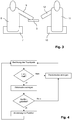
- ein vereinfachtes Flussdiagramm eines erfindungsgemäßen Verfahrens;
- Fig. 3
- eine vereinfachte Darstellung einer Identifikation eines Bedieners;
- Fig. 4
- ein vereinfachtes Flussdiagramm der Bedienung eines Bedienmenüs;
- Fig. 5
- die Darstellung eines Berührpunkts und einer simulierten Hand eines Bedieners auf einem Bildschirm.
- Fig. 1
- a cockpit of a passenger car equipped with a device according to the invention and a basic circuit diagram of such a device;
- Fig. 2
- a simplified flow diagram of a method according to the invention;
- Fig. 3
- a simplified representation of an identification of an operator;
- Fig. 4
- a simplified flow chart of the operation of an operating menu;
- Fig. 5
- the representation of a touch point and a simulated hand of an operator on a screen.
Wie im rechten Teil von
Das Touchpad 3 kann auch vom Beifahrer bequem erreicht werden, und zwar mit der linken Hand. In der in
Das Touchpad 3 kann mit einem Finger berührt werden, um beispielsweise innerhalb eines Bedienmenüs bestimmte Menüpunkte auszuwählen und zu aktivieren, etwa zur Bedienung einer Radioanlage des Fahrzeugs. Wie im linken Teil von
Während das Touchpad 3 bequem mit der rechten Hand des Fahrers erreichbar ist, ist es für den Fahrer nicht ohne weiteres einfach erkennbar, auf welcher Position des Touchpads 3 eine Eingabe vorgenommen wird. Hierfür müsste der Fahrer seine Blickrichtung stark ändern, um das Touchpad 3 und seine zur Bedienung des Touchpads 3 benutzte Hand sehen zu können; ferner wäre eine Fokussierung auf eine relativ geringe Distanz notwendig. Um die Bedienung des Touchpad 3 zu erleichtern, wird daher das Bedienmenü auf dem Bildschirm 4 angezeigt und ebenso eine simulierte Hand des Bedieners in einer Position und Orientierung, die der der Hand relativ zum Touchpad 3 entspricht, zusammen mit einem Berührpunkt, in dem durch Druck mit dem Finger eine Eingabe erfolgen kann.While the
Hierfür wird, wie in
Ist nun festgestellt, welcher der Insassen des Fahrzeugs das Touchpad 3 bedient, so wird gemäß dem in
In
Eine mögliche Darstellungsweise auf dem Bildschirm 4 ist in
Da im vorliegenden Fall der Bediener, insbesondere, wenn es sich um den Fahrer handelt, die Bedienfläche nicht oder nicht ständig im Blickfeld hat, wird eine virtuelle Hand 16, 18 des Bedieners zusammen mit dem zu bedienenden Menü auf der Anzeigeeinrichtung (Bildschirm 4, siehe
Claims (8)
- Method for displaying a hand of an operator of an operating element of a vehicle on a display device of the vehicle, contact between an operating area of the operating element and the operator's hand being detected and a position of a point of contact being determined, the operator being identified, an orientation of the hand being determined, and an image of an accordingly oriented virtual hand (16, 18) being displayed on the display device in such a manner that a tip of a finger corresponds to the position of the point of contact,
characterized in that
a sitting position of the operator is captured and the orientation of the hand and/or a hand size is/are determined from the sitting position with the aid of a model of the operator and/or a table. - Method according to Claim 1,
characterized in that
the operator is identified by means of at least one seat occupancy sensor. - Method according to one of the preceding claims,
characterized in that
the operator is identified by closing a circuit via the operator's hand. - Method according to one of the preceding claims,
characterized in that
the operating area is arranged in a center console (2) of the vehicle, and the operator is identified by means of a sensor arranged to the side of the operating area for the purpose of detecting an operator's hand and/or arm (9). - Method according to one of the preceding claims,
characterized in that
the sitting position is captured by capturing the position of at least one adjustment element of the operator's seat (7). - Method according to one of the preceding claims,
characterized in that
the point of contact is displayed on the display device. - Method according to one of the preceding claims,
characterized in that
the position of the point of contact is determined taking into account the determined orientation of the hand. - Apparatus for displaying a hand of an operator of an operating element of a vehicle, comprising an operating element which comprises an operating area or is in the form of such an operating area, the operating area being designed to detect contact by the operator's hand and to determine the point of contact, also comprising first sensor means for identifying an operator of the operating element and a display device for displaying an image of a virtual hand (16, 18) in the correct position relative to the point of contact,
characterized in that
the apparatus comprises second sensor means for capturing a sitting position of the operator and memory and processor means for determining an orientation of the hand on the basis of the signals from the first and second sensor means.
Applications Claiming Priority (1)
| Application Number | Priority Date | Filing Date | Title |
|---|---|---|---|
| DE102012206247A DE102012206247A1 (en) | 2012-04-17 | 2012-04-17 | Method and device for displaying a hand of an operator of a control element of a vehicle |
Publications (3)
| Publication Number | Publication Date |
|---|---|
| EP2653335A2 EP2653335A2 (en) | 2013-10-23 |
| EP2653335A3 EP2653335A3 (en) | 2018-04-18 |
| EP2653335B1 true EP2653335B1 (en) | 2020-04-01 |
Family
ID=48184018
Family Applications (1)
| Application Number | Title | Priority Date | Filing Date |
|---|---|---|---|
| EP13163754.8A Active EP2653335B1 (en) | 2012-04-17 | 2013-04-15 | Method and apparatus for displaying a hand of an operator of an operating element of a vehicle |
Country Status (4)
| Country | Link |
|---|---|
| EP (1) | EP2653335B1 (en) |
| CN (1) | CN103373294B (en) |
| DE (1) | DE102012206247A1 (en) |
| RU (1) | RU2617621C2 (en) |
Families Citing this family (10)
| Publication number | Priority date | Publication date | Assignee | Title |
|---|---|---|---|---|
| WO2017072939A1 (en) * | 2015-10-30 | 2017-05-04 | 三菱電機株式会社 | Vehicle information display control device, and method for displaying automatic driving information |
| US10281990B2 (en) * | 2016-12-07 | 2019-05-07 | Ford Global Technologies, Llc | Vehicle user input control system and method |
| DE102017201799A1 (en) | 2017-02-06 | 2018-08-09 | Volkswagen Aktiengesellschaft | User interface, means of transport and method of user discrimination |
| DE102017110787A1 (en) * | 2017-05-18 | 2018-11-22 | Valeo Schalter Und Sensoren Gmbh | Operating device for a motor vehicle for selecting and / or setting an operating function, wherein an optical symbol is displayed on a first or second display unit, driver assistance system, motor vehicle and method |
| US11221711B2 (en) | 2018-05-14 | 2022-01-11 | Mitsubishi Electric Corporation | Input control device, input control method and display device that estimate operator position relative to a touch panel |
| DE102018221704A1 (en) | 2018-12-13 | 2020-06-18 | Volkswagen Aktiengesellschaft | Operating system for a vehicle |
| DE102018221706A1 (en) * | 2018-12-13 | 2020-06-18 | Volkswagen Aktiengesellschaft | Operating system for a vehicle |
| DE102019213858A1 (en) * | 2019-09-11 | 2021-03-11 | Zf Friedrichshafen Ag | Operating device for a vehicle, steering wheel, dashboard, center console or armrest for a vehicle with an operating device, vehicle with an operating device and method for operating an operating device |
| CN111404535A (en) * | 2020-03-20 | 2020-07-10 | 宁波吉利汽车研究开发有限公司 | Steering wheel switch control system of vehicle and control method thereof |
| DE102022102504B9 (en) * | 2022-02-03 | 2023-07-20 | Audi Aktiengesellschaft | Method for operating an interface device in a vehicle, and interface device and vehicle |
Family Cites Families (10)
| Publication number | Priority date | Publication date | Assignee | Title |
|---|---|---|---|---|
| JP4351599B2 (en) * | 2004-09-03 | 2009-10-28 | パナソニック株式会社 | Input device |
| DE102005056458B4 (en) | 2005-11-26 | 2016-01-14 | Daimler Ag | Operating device for a vehicle |
| JP4333697B2 (en) * | 2006-06-06 | 2009-09-16 | トヨタ自動車株式会社 | Vehicle display device |
| JP4356763B2 (en) * | 2007-01-30 | 2009-11-04 | トヨタ自動車株式会社 | Operating device |
| US8094189B2 (en) * | 2007-01-30 | 2012-01-10 | Toyota Jidosha Kabushiki Kaisha | Operating device |
| RU2373081C2 (en) * | 2007-03-26 | 2009-11-20 | Общество с ограниченной ответственностью "Мехатроника" | System to control service function of vehicles |
| GB0719037D0 (en) * | 2007-09-28 | 2007-11-07 | Vitrolife Sweden Ab | Sampling needle |
| US20100188204A1 (en) * | 2007-10-15 | 2010-07-29 | Reiko Okada | Display device for vehicle |
| RU85245U1 (en) * | 2009-02-13 | 2009-07-27 | Общество с ограниченной ответственностью "Мехатроника" | ON-BOARD CAR COMPUTER FOR MANAGING SERVICE FUNCTIONS IN VEHICLES |
| DE102009057739A1 (en) | 2009-12-10 | 2010-07-22 | Daimler Ag | Operating device for vehicle, has operating element with control button, where place of user finger on control button is detected by detecting device |
-
2012
- 2012-04-17 DE DE102012206247A patent/DE102012206247A1/en active Pending
-
2013
- 2013-04-15 EP EP13163754.8A patent/EP2653335B1/en active Active
- 2013-04-16 RU RU2013117415A patent/RU2617621C2/en not_active IP Right Cessation
- 2013-04-16 CN CN201310132156.0A patent/CN103373294B/en active Active
Non-Patent Citations (1)
| Title |
|---|
| None * |
Also Published As
| Publication number | Publication date |
|---|---|
| CN103373294B (en) | 2017-01-18 |
| DE102012206247A1 (en) | 2013-10-17 |
| RU2013117415A (en) | 2014-10-27 |
| EP2653335A2 (en) | 2013-10-23 |
| CN103373294A (en) | 2013-10-30 |
| EP2653335A3 (en) | 2018-04-18 |
| RU2617621C2 (en) | 2017-04-25 |
Similar Documents
| Publication | Publication Date | Title |
|---|---|---|
| EP2653335B1 (en) | Method and apparatus for displaying a hand of an operator of an operating element of a vehicle | |
| EP3507681B1 (en) | Method for interacting with image contents displayed on a display device in a vehicle | |
| DE102017209562B4 (en) | Method for operating a display arrangement of a motor vehicle, operating device, and motor vehicle | |
| DE102017113763B4 (en) | Method for operating a display device for a motor vehicle and motor vehicle | |
| DE102012216181A1 (en) | System for gesture-based adjustment of seat mounted in vehicle by user, has control unit that controls setting of vehicle seat associated with recognized gesture and gesture area | |
| DE102011112445A1 (en) | Multi-functional control device | |
| WO2021023468A1 (en) | Device and method for controlling a passenger seat in a vehicle | |
| DE102013020950B4 (en) | Method for operating a rear view camera system of a motor vehicle, rear view camera system and motor vehicle | |
| EP3254172B1 (en) | Determination of a position of a non-vehicle object in a vehicle | |
| EP3508967A1 (en) | Human-machine interface and method for operating a human-machine interface | |
| DE102018127880A1 (en) | Gesture determination device and program | |
| DE102013217558A1 (en) | Method for controlling an information display device and device with an information display device | |
| DE102012018685B4 (en) | System and method for controlling at least one vehicle system by means of gestures carried out by a driver | |
| WO2015162058A1 (en) | Gesture interaction with a driver information system of a vehicle | |
| DE102013000069B4 (en) | Motor vehicle user interface with a control element for detecting a control action | |
| DE102015012720A1 (en) | Interactive operator system and method for performing an operator action in an interactive operator system | |
| DE102017117094A1 (en) | Customizable representation of an environment of a motor vehicle by a driver assistance device | |
| DE102017206312A1 (en) | Support handling of an object located within a passenger compartment and motor vehicle | |
| DE102020214908B4 (en) | Method and device for monitoring the line of sight of a driver when driving a motor vehicle | |
| DE102012218155A1 (en) | Method for preparation of input for rider of e.g. passenger car on touch-sensitive display, involves displaying a section of graphical interface on display unit, in response to detecting that driver needs to perform the input process | |
| DE102019127183A1 (en) | Display system for displaying an operating instruction for an operating element in a motor vehicle | |
| DE102022102504B9 (en) | Method for operating an interface device in a vehicle, and interface device and vehicle | |
| DE102014222752A1 (en) | Operation via head direction as a replacement for the viewing direction | |
| DE102013019263B4 (en) | Method for operating an operating device and vehicle with an operating device | |
| DE102022110485B4 (en) | Method and control system for calling up functions and operating settings of a vehicle |
Legal Events
| Date | Code | Title | Description |
|---|---|---|---|
| PUAI | Public reference made under article 153(3) epc to a published international application that has entered the european phase |
Free format text: ORIGINAL CODE: 0009012 |
|
| AK | Designated contracting states |
Kind code of ref document: A2 Designated state(s): AL AT BE BG CH CY CZ DE DK EE ES FI FR GB GR HR HU IE IS IT LI LT LU LV MC MK MT NL NO PL PT RO RS SE SI SK SM TR |
|
| AX | Request for extension of the european patent |
Extension state: BA ME |
|
| PUAL | Search report despatched |
Free format text: ORIGINAL CODE: 0009013 |
|
| AK | Designated contracting states |
Kind code of ref document: A3 Designated state(s): AL AT BE BG CH CY CZ DE DK EE ES FI FR GB GR HR HU IE IS IT LI LT LU LV MC MK MT NL NO PL PT RO RS SE SI SK SM TR |
|
| AX | Request for extension of the european patent |
Extension state: BA ME |
|
| RIC1 | Information provided on ipc code assigned before grant |
Ipc: B60K 37/06 20060101AFI20180309BHEP Ipc: B60K 35/00 20060101ALI20180309BHEP |
|
| STAA | Information on the status of an ep patent application or granted ep patent |
Free format text: STATUS: REQUEST FOR EXAMINATION WAS MADE |
|
| 17P | Request for examination filed |
Effective date: 20181018 |
|
| RBV | Designated contracting states (corrected) |
Designated state(s): AL AT BE BG CH CY CZ DE DK EE ES FI FR GB GR HR HU IE IS IT LI LT LU LV MC MK MT NL NO PL PT RO RS SE SI SK SM TR |
|
| GRAP | Despatch of communication of intention to grant a patent |
Free format text: ORIGINAL CODE: EPIDOSNIGR1 |
|
| STAA | Information on the status of an ep patent application or granted ep patent |
Free format text: STATUS: GRANT OF PATENT IS INTENDED |
|
| INTG | Intention to grant announced |
Effective date: 20200124 |
|
| GRAS | Grant fee paid |
Free format text: ORIGINAL CODE: EPIDOSNIGR3 |
|
| GRAA | (expected) grant |
Free format text: ORIGINAL CODE: 0009210 |
|
| STAA | Information on the status of an ep patent application or granted ep patent |
Free format text: STATUS: THE PATENT HAS BEEN GRANTED |
|
| AK | Designated contracting states |
Kind code of ref document: B1 Designated state(s): AL AT BE BG CH CY CZ DE DK EE ES FI FR GB GR HR HU IE IS IT LI LT LU LV MC MK MT NL NO PL PT RO RS SE SI SK SM TR |
|
| REG | Reference to a national code |
Ref country code: GB Ref legal event code: FG4D Free format text: NOT ENGLISH |
|
| REG | Reference to a national code |
Ref country code: CH Ref legal event code: EP Ref country code: AT Ref legal event code: REF Ref document number: 1250930 Country of ref document: AT Kind code of ref document: T Effective date: 20200415 |
|
| REG | Reference to a national code |
Ref country code: DE Ref legal event code: R096 Ref document number: 502013014509 Country of ref document: DE |
|
| REG | Reference to a national code |
Ref country code: IE Ref legal event code: FG4D Free format text: LANGUAGE OF EP DOCUMENT: GERMAN |
|
| PG25 | Lapsed in a contracting state [announced via postgrant information from national office to epo] |
Ref country code: BG Free format text: LAPSE BECAUSE OF FAILURE TO SUBMIT A TRANSLATION OF THE DESCRIPTION OR TO PAY THE FEE WITHIN THE PRESCRIBED TIME-LIMIT Effective date: 20200701 |
|
| REG | Reference to a national code |
Ref country code: NL Ref legal event code: MP Effective date: 20200401 |
|
| REG | Reference to a national code |
Ref country code: LT Ref legal event code: MG4D |
|
| PG25 | Lapsed in a contracting state [announced via postgrant information from national office to epo] |
Ref country code: SE Free format text: LAPSE BECAUSE OF FAILURE TO SUBMIT A TRANSLATION OF THE DESCRIPTION OR TO PAY THE FEE WITHIN THE PRESCRIBED TIME-LIMIT Effective date: 20200401 Ref country code: NL Free format text: LAPSE BECAUSE OF FAILURE TO SUBMIT A TRANSLATION OF THE DESCRIPTION OR TO PAY THE FEE WITHIN THE PRESCRIBED TIME-LIMIT Effective date: 20200401 Ref country code: FI Free format text: LAPSE BECAUSE OF FAILURE TO SUBMIT A TRANSLATION OF THE DESCRIPTION OR TO PAY THE FEE WITHIN THE PRESCRIBED TIME-LIMIT Effective date: 20200401 Ref country code: GR Free format text: LAPSE BECAUSE OF FAILURE TO SUBMIT A TRANSLATION OF THE DESCRIPTION OR TO PAY THE FEE WITHIN THE PRESCRIBED TIME-LIMIT Effective date: 20200702 Ref country code: NO Free format text: LAPSE BECAUSE OF FAILURE TO SUBMIT A TRANSLATION OF THE DESCRIPTION OR TO PAY THE FEE WITHIN THE PRESCRIBED TIME-LIMIT Effective date: 20200701 Ref country code: PT Free format text: LAPSE BECAUSE OF FAILURE TO SUBMIT A TRANSLATION OF THE DESCRIPTION OR TO PAY THE FEE WITHIN THE PRESCRIBED TIME-LIMIT Effective date: 20200817 Ref country code: CZ Free format text: LAPSE BECAUSE OF FAILURE TO SUBMIT A TRANSLATION OF THE DESCRIPTION OR TO PAY THE FEE WITHIN THE PRESCRIBED TIME-LIMIT Effective date: 20200401 Ref country code: LT Free format text: LAPSE BECAUSE OF FAILURE TO SUBMIT A TRANSLATION OF THE DESCRIPTION OR TO PAY THE FEE WITHIN THE PRESCRIBED TIME-LIMIT Effective date: 20200401 Ref country code: IS Free format text: LAPSE BECAUSE OF FAILURE TO SUBMIT A TRANSLATION OF THE DESCRIPTION OR TO PAY THE FEE WITHIN THE PRESCRIBED TIME-LIMIT Effective date: 20200801 |
|
| PG25 | Lapsed in a contracting state [announced via postgrant information from national office to epo] |
Ref country code: RS Free format text: LAPSE BECAUSE OF FAILURE TO SUBMIT A TRANSLATION OF THE DESCRIPTION OR TO PAY THE FEE WITHIN THE PRESCRIBED TIME-LIMIT Effective date: 20200401 Ref country code: LV Free format text: LAPSE BECAUSE OF FAILURE TO SUBMIT A TRANSLATION OF THE DESCRIPTION OR TO PAY THE FEE WITHIN THE PRESCRIBED TIME-LIMIT Effective date: 20200401 Ref country code: HR Free format text: LAPSE BECAUSE OF FAILURE TO SUBMIT A TRANSLATION OF THE DESCRIPTION OR TO PAY THE FEE WITHIN THE PRESCRIBED TIME-LIMIT Effective date: 20200401 |
|
| REG | Reference to a national code |
Ref country code: CH Ref legal event code: PL |
|
| PG25 | Lapsed in a contracting state [announced via postgrant information from national office to epo] |
Ref country code: AL Free format text: LAPSE BECAUSE OF FAILURE TO SUBMIT A TRANSLATION OF THE DESCRIPTION OR TO PAY THE FEE WITHIN THE PRESCRIBED TIME-LIMIT Effective date: 20200401 |
|
| REG | Reference to a national code |
Ref country code: DE Ref legal event code: R097 Ref document number: 502013014509 Country of ref document: DE |
|
| PG25 | Lapsed in a contracting state [announced via postgrant information from national office to epo] |
Ref country code: LI Free format text: LAPSE BECAUSE OF NON-PAYMENT OF DUE FEES Effective date: 20200430 Ref country code: DK Free format text: LAPSE BECAUSE OF FAILURE TO SUBMIT A TRANSLATION OF THE DESCRIPTION OR TO PAY THE FEE WITHIN THE PRESCRIBED TIME-LIMIT Effective date: 20200401 Ref country code: LU Free format text: LAPSE BECAUSE OF NON-PAYMENT OF DUE FEES Effective date: 20200415 Ref country code: RO Free format text: LAPSE BECAUSE OF FAILURE TO SUBMIT A TRANSLATION OF THE DESCRIPTION OR TO PAY THE FEE WITHIN THE PRESCRIBED TIME-LIMIT Effective date: 20200401 Ref country code: SM Free format text: LAPSE BECAUSE OF FAILURE TO SUBMIT A TRANSLATION OF THE DESCRIPTION OR TO PAY THE FEE WITHIN THE PRESCRIBED TIME-LIMIT Effective date: 20200401 Ref country code: IT Free format text: LAPSE BECAUSE OF FAILURE TO SUBMIT A TRANSLATION OF THE DESCRIPTION OR TO PAY THE FEE WITHIN THE PRESCRIBED TIME-LIMIT Effective date: 20200401 Ref country code: EE Free format text: LAPSE BECAUSE OF FAILURE TO SUBMIT A TRANSLATION OF THE DESCRIPTION OR TO PAY THE FEE WITHIN THE PRESCRIBED TIME-LIMIT Effective date: 20200401 Ref country code: ES Free format text: LAPSE BECAUSE OF FAILURE TO SUBMIT A TRANSLATION OF THE DESCRIPTION OR TO PAY THE FEE WITHIN THE PRESCRIBED TIME-LIMIT Effective date: 20200401 Ref country code: MC Free format text: LAPSE BECAUSE OF FAILURE TO SUBMIT A TRANSLATION OF THE DESCRIPTION OR TO PAY THE FEE WITHIN THE PRESCRIBED TIME-LIMIT Effective date: 20200401 Ref country code: CH Free format text: LAPSE BECAUSE OF NON-PAYMENT OF DUE FEES Effective date: 20200430 |
|
| REG | Reference to a national code |
Ref country code: BE Ref legal event code: MM Effective date: 20200430 |
|
| PLBE | No opposition filed within time limit |
Free format text: ORIGINAL CODE: 0009261 |
|
| STAA | Information on the status of an ep patent application or granted ep patent |
Free format text: STATUS: NO OPPOSITION FILED WITHIN TIME LIMIT |
|
| PG25 | Lapsed in a contracting state [announced via postgrant information from national office to epo] |
Ref country code: PL Free format text: LAPSE BECAUSE OF FAILURE TO SUBMIT A TRANSLATION OF THE DESCRIPTION OR TO PAY THE FEE WITHIN THE PRESCRIBED TIME-LIMIT Effective date: 20200401 Ref country code: SK Free format text: LAPSE BECAUSE OF FAILURE TO SUBMIT A TRANSLATION OF THE DESCRIPTION OR TO PAY THE FEE WITHIN THE PRESCRIBED TIME-LIMIT Effective date: 20200401 Ref country code: BE Free format text: LAPSE BECAUSE OF NON-PAYMENT OF DUE FEES Effective date: 20200430 |
|
| 26N | No opposition filed |
Effective date: 20210112 |
|
| PG25 | Lapsed in a contracting state [announced via postgrant information from national office to epo] |
Ref country code: IE Free format text: LAPSE BECAUSE OF NON-PAYMENT OF DUE FEES Effective date: 20200415 |
|
| PG25 | Lapsed in a contracting state [announced via postgrant information from national office to epo] |
Ref country code: SI Free format text: LAPSE BECAUSE OF FAILURE TO SUBMIT A TRANSLATION OF THE DESCRIPTION OR TO PAY THE FEE WITHIN THE PRESCRIBED TIME-LIMIT Effective date: 20200401 |
|
| REG | Reference to a national code |
Ref country code: AT Ref legal event code: MM01 Ref document number: 1250930 Country of ref document: AT Kind code of ref document: T Effective date: 20200415 |
|
| PG25 | Lapsed in a contracting state [announced via postgrant information from national office to epo] |
Ref country code: AT Free format text: LAPSE BECAUSE OF NON-PAYMENT OF DUE FEES Effective date: 20200415 |
|
| PG25 | Lapsed in a contracting state [announced via postgrant information from national office to epo] |
Ref country code: TR Free format text: LAPSE BECAUSE OF FAILURE TO SUBMIT A TRANSLATION OF THE DESCRIPTION OR TO PAY THE FEE WITHIN THE PRESCRIBED TIME-LIMIT Effective date: 20200401 Ref country code: MT Free format text: LAPSE BECAUSE OF FAILURE TO SUBMIT A TRANSLATION OF THE DESCRIPTION OR TO PAY THE FEE WITHIN THE PRESCRIBED TIME-LIMIT Effective date: 20200401 Ref country code: CY Free format text: LAPSE BECAUSE OF FAILURE TO SUBMIT A TRANSLATION OF THE DESCRIPTION OR TO PAY THE FEE WITHIN THE PRESCRIBED TIME-LIMIT Effective date: 20200401 |
|
| PGFP | Annual fee paid to national office [announced via postgrant information from national office to epo] |
Ref country code: FR Payment date: 20220324 Year of fee payment: 10 |
|
| PG25 | Lapsed in a contracting state [announced via postgrant information from national office to epo] |
Ref country code: MK Free format text: LAPSE BECAUSE OF FAILURE TO SUBMIT A TRANSLATION OF THE DESCRIPTION OR TO PAY THE FEE WITHIN THE PRESCRIBED TIME-LIMIT Effective date: 20200401 |
|
| PGFP | Annual fee paid to national office [announced via postgrant information from national office to epo] |
Ref country code: GB Payment date: 20230315 Year of fee payment: 11 |
|
| P01 | Opt-out of the competence of the unified patent court (upc) registered |
Effective date: 20230620 |
|
| PGFP | Annual fee paid to national office [announced via postgrant information from national office to epo] |
Ref country code: DE Payment date: 20230320 Year of fee payment: 11 |
|
| REG | Reference to a national code |
Ref country code: DE Ref legal event code: R079 Ref document number: 502013014509 Country of ref document: DE Free format text: PREVIOUS MAIN CLASS: B60K0037060000 Ipc: B60K0035100000 |
|
| PG25 | Lapsed in a contracting state [announced via postgrant information from national office to epo] |
Ref country code: FR Free format text: LAPSE BECAUSE OF NON-PAYMENT OF DUE FEES Effective date: 20230430 |
|
| REG | Reference to a national code |
Ref country code: DE Ref legal event code: R084 Ref document number: 502013014509 Country of ref document: DE |