EP2647841A1 - Solar thermal power system - Google Patents
Solar thermal power system Download PDFInfo
- Publication number
- EP2647841A1 EP2647841A1 EP12162906.7A EP12162906A EP2647841A1 EP 2647841 A1 EP2647841 A1 EP 2647841A1 EP 12162906 A EP12162906 A EP 12162906A EP 2647841 A1 EP2647841 A1 EP 2647841A1
- Authority
- EP
- European Patent Office
- Prior art keywords
- steam
- turbine
- operating mode
- high pressure
- during
- Prior art date
- Legal status (The legal status is an assumption and is not a legal conclusion. Google has not performed a legal analysis and makes no representation as to the accuracy of the status listed.)
- Granted
Links
- 238000004146 energy storage Methods 0.000 claims abstract description 57
- 239000012530 fluid Substances 0.000 claims abstract description 37
- 238000011017 operating method Methods 0.000 claims description 20
- 238000001816 cooling Methods 0.000 claims description 17
- 238000002347 injection Methods 0.000 claims description 5
- 239000007924 injection Substances 0.000 claims description 5
- 238000010438 heat treatment Methods 0.000 claims description 4
- 238000000034 method Methods 0.000 claims description 2
- 150000003839 salts Chemical class 0.000 description 36
- 230000005855 radiation Effects 0.000 description 14
- 238000007599 discharging Methods 0.000 description 6
- XLYOFNOQVPJJNP-UHFFFAOYSA-N water Substances O XLYOFNOQVPJJNP-UHFFFAOYSA-N 0.000 description 6
- 238000010248 power generation Methods 0.000 description 5
- 238000005516 engineering process Methods 0.000 description 3
- 239000007788 liquid Substances 0.000 description 2
- 239000000203 mixture Substances 0.000 description 2
- 239000000243 solution Substances 0.000 description 2
- 238000012546 transfer Methods 0.000 description 2
- 150000005323 carbonate salts Chemical class 0.000 description 1
- 125000004122 cyclic group Chemical group 0.000 description 1
- 230000001419 dependent effect Effects 0.000 description 1
- 238000011161 development Methods 0.000 description 1
- 230000005611 electricity Effects 0.000 description 1
- 238000004519 manufacturing process Methods 0.000 description 1
- -1 mixtures of salts Chemical class 0.000 description 1
- 238000012986 modification Methods 0.000 description 1
- 230000004048 modification Effects 0.000 description 1
- 150000002823 nitrates Chemical class 0.000 description 1
- 230000003287 optical effect Effects 0.000 description 1
- 238000011084 recovery Methods 0.000 description 1
- 239000007787 solid Substances 0.000 description 1
- 230000009747 swallowing Effects 0.000 description 1
- 230000008646 thermal stress Effects 0.000 description 1
Images


Classifications
-
- F—MECHANICAL ENGINEERING; LIGHTING; HEATING; WEAPONS; BLASTING
- F03—MACHINES OR ENGINES FOR LIQUIDS; WIND, SPRING, OR WEIGHT MOTORS; PRODUCING MECHANICAL POWER OR A REACTIVE PROPULSIVE THRUST, NOT OTHERWISE PROVIDED FOR
- F03G—SPRING, WEIGHT, INERTIA OR LIKE MOTORS; MECHANICAL-POWER PRODUCING DEVICES OR MECHANISMS, NOT OTHERWISE PROVIDED FOR OR USING ENERGY SOURCES NOT OTHERWISE PROVIDED FOR
- F03G6/00—Devices for producing mechanical power from solar energy
- F03G6/06—Devices for producing mechanical power from solar energy with solar energy concentrating means
- F03G6/065—Devices for producing mechanical power from solar energy with solar energy concentrating means having a Rankine cycle
-
- Y—GENERAL TAGGING OF NEW TECHNOLOGICAL DEVELOPMENTS; GENERAL TAGGING OF CROSS-SECTIONAL TECHNOLOGIES SPANNING OVER SEVERAL SECTIONS OF THE IPC; TECHNICAL SUBJECTS COVERED BY FORMER USPC CROSS-REFERENCE ART COLLECTIONS [XRACs] AND DIGESTS
- Y02—TECHNOLOGIES OR APPLICATIONS FOR MITIGATION OR ADAPTATION AGAINST CLIMATE CHANGE
- Y02E—REDUCTION OF GREENHOUSE GAS [GHG] EMISSIONS, RELATED TO ENERGY GENERATION, TRANSMISSION OR DISTRIBUTION
- Y02E10/00—Energy generation through renewable energy sources
- Y02E10/40—Solar thermal energy, e.g. solar towers
- Y02E10/46—Conversion of thermal power into mechanical power, e.g. Rankine, Stirling or solar thermal engines
Definitions
- the present disclosure relates generally to the field of concentrated solar power (CSP).
- Embodiments of the present disclosure relate to a solar thermal power system that utilises concentrated solar power to generate electricity and/or to an operating method for a solar thermal power system.
- Concentrated solar power involves the use of lenses, mirrors or other optical devices to focus solar radiation from a large incident area onto a small area. The energy from the solar radiation is then used to generate electrical power. Concentrated solar power has the potential to become an important energy source in the future.
- the technology believed to have the most potential for providing high efficiency power generation is the concentrated solar thermal power system.
- This technology involves the use of a solar receiver steam generator, mounted atop a tower, onto which solar radiation is reflected by an array of tracking reflectors, typically heliostats forming a heliostat field around the tower.
- the reflected solar radiation directly heats water circulating through the solar receiver steam generator. This generates superheated steam which is used to drive a steam turbine generator set, and thereby generate electrical power, in a well-known manner using the Rankine cycle.
- Concentrated solar thermal power systems typically have energy storage capability so that they can continue to generate electrical power when the solar radiation reflected onto the solar receiver steam generator is not sufficient to generate steam at the required pressure and temperature to drive the steam turbine generator set.
- the energy storage capability is typically provided by a thermal energy storage arrangement which uses a high specific heat capacity thermal energy storage fluid, typically molten salt or a mixture of different molten salts. Thermal energy is stored during a charging cycle by heating the molten salt and the thermal energy is subsequently recovered during a discharging cycle to heat water, and thereby generate steam for the steam turbine generator set.
- a proportion of superheated steam generated by the solar receiver steam generator is supplied directly to the high pressure turbine inlet of the steam turbine generator set for electrical power generation.
- the remaining superheated steam is supplied to the thermal energy storage arrangement to support the charging cycle in which a heat exchanger is used to extract thermal energy from the superheated steam and transfer it to the molten salt.
- the heated molten salt is stored in an insulated storage container.
- the steam generated by the thermal energy storage arrangement during the second operating mode should ideally have the same temperature and pressure as the steam generated by the solar receiver steam generator during the first operating mode.
- the maximum temperature that can be attained by the molten salt is lower than the maximum temperature of the steam from which the thermal energy is extracted. This results in exergy loss (also known as a 'pinch point loss') and occurs because as the superheated steam cools in the heat exchanger during the charging cycle, it changes state to condensed water.
- the generated steam attains a lower pressure (possibly greater than 20% lower) and a lower temperature (possibly greater than 30°C to 100°C or more lower depending on the thermal energy storage arrangement that is used) than the superheated steam that was used to heat the molten salt and drive the steam turbine generator set during the first operating mode.
- a lower pressure possibly greater than 20% lower
- a lower temperature possibly greater than 30°C to 100°C or more lower depending on the thermal energy storage arrangement that is used
- the steam turbine generator set operates in a part-load condition which reduces power output of the solar thermal power system. It is not uncommon for the power output to be more than 20% lower during the second operating mode than during the first operating mode (when a proportion of the superheated steam from the solar receiver steam generator is supplied directly to the high pressure turbine inlet of the steam turbine generator set).
- a solar thermal power system comprising a solar receiver steam generator, a thermal energy storage arrangement including a thermal energy storage fluid, and a multistage steam turbine for driving an electrical generator to produce electrical power, wherein the solar thermal power system has:
- a method for operating a solar thermal power system comprising a solar receiver steam generator, a thermal energy storage arrangement including a thermal energy storage fluid, and a multistage steam turbine for driving an electrical generator to produce electrical power, wherein the solar thermal power system has:
- the power output of the multistage steam turbine are considerably increased.
- the power output during the second operating mode of the solar thermal power system may be similar to the power output during the first operating mode when steam from the solar receiver steam generator is supplied directly to the high pressure turbine inlet.
- the power output of the steam turbine is dependent upon the mass flow rate of steam through the turbine, so in order to increase power output it is necessary to increase the steam mass flow rate. Since modern steam turbines have a fixed swallowing capacity and therefore operate with a constant volume flow rate of steam, it is necessary to vary the steam pressure and temperature to vary the mass flow rate. According to the present disclosure, the lower pressure and lower temperature steam injected at the downstream location during the second operating mode has a higher pressure than steam at the corresponding location or stage during the first operating mode that has been supplied to the high pressure turbine inlet and expanded through the turbine to that location, such expansion serving to reduce the steam pressure and thereby extracting work.
- the mass flow rate of steam through the steam turbine at the downstream location is thus greater during the second operating mode than during the first operating mode, and this increases the power output of the turbine stage(s) downstream of the injection location and, hence, the power output of the steam turbine during the second operating mode.
- Bypassing the high pressure turbine inlet during the second operating mode also has the advantage that it minimises thermal stresses at the high pressure turbine inlet because it is not subjected to different steam temperatures during the first and second operating modes. Cyclic operation, between the first and second operating modes, occurs frequently, for example during daily start-up and overcast conditions when there are load fluctuations.
- a stage In the field of steam turbines a stage is usually referred to as the location of a adjacent pair of guide vanes and rotating blades or airfoils. All stages together form the steam path through the turbine. And typically at a given feed pressure the pressure drop along the steam path is well defined thus giving each stage a nominal pressure at the first operational mode.
- the multistage steam turbine may include a high pressure stage and the high pressure turbine inlet may be provided at an inlet region of the high pressure stage. Steam generated by the solar receiver steam generator during the first operating mode may thus be initially expanded in the high pressure turbine stage during the first operating mode.
- the multistage steam turbine may include one or more lower pressure stages downstream of the high pressure stage and typically includes an intermediate pressure stage and a low pressure stage.
- the solar thermal power system may be arranged to inject the lower pressure and lower temperature steam generated during the second operating mode into one of the lower pressure stages to drive the steam turbine.
- the solar thermal power system may be arranged to inject the lower pressure and lower temperature steam generated during the second operating mode into the intermediate pressure stage to drive the steam turbine.
- it is the intermediate pressure stage that is compatible with the lower pressure and lower temperature of the steam generated during the second operating mode.
- the lower pressure and lower temperature steam is, thus, initially expanded in the intermediate pressure stage and thereafter expanded in the low pressure stage during the second operating mode. Very little or no Steam is expanded in the bypassed high pressure stage during the second operating mode and the high pressure stage does not, thus, contribute to the power output of the turbine.
- the high pressure stage may include a first section and a second section downstream of the first section.
- the solar thermal power system may be arranged to inject the lower pressure and lower temperature steam generated during the second operating mode into the second section of the high pressure stage.
- it is the second section of the high pressure stage that is compatible with the lower pressure and lower temperature of the steam generated during the second operating mode.
- the lower pressure and lower temperature steam is, thus, initially expanded in the second section of the high pressure stage and thereafter may be expanded in the lower pressure stage(s) during the second operating mode. Steam is not expanded in the bypassed first section of the high pressure stage during the second operating mode and the first section does not, thus, contribute to the power output of the turbine.
- the solar thermal power system may be arranged to supply a small proportion of the lower pressure and lower temperature steam generated by the thermal energy storage arrangement during the second operating mode to the high pressure turbine inlet to act as a cooling flow for the high pressure region of the steam turbine.
- the cooling flow thus prevents the high pressure region, for example the high pressure stage or the first section of the high pressure stage, of the steam turbine from running empty.
- the solar thermal power system may include a heater, for example an electrical superheater, to heat the cooling flow prior to injection into the high pressure turbine inlet. This may advantageously prevent excessive cool-down of the high pressure region, for example the high pressure stage or the first section of the high pressure stage.
- the solar thermal power system may include a condenser which may be connected to the high pressure region of the steam turbine, for example the high pressure stage or the first section of the high pressure stage, during the second operating mode.
- the condenser maintains the high pressure region at a low pressure and thus avoids excessive temperatures in the high pressure region when a cooling flow as described above is not provided to the high pressure region.
- the solar thermal power system may include a clutch device to decouple the high pressure region of the steam turbine during the second operating mode.
- the clutch device may be arranged between the high pressure region of the steam turbine, for example the high pressure stage or the first section of the high pressure stage, and the electrical generator.
- the clutch device may be arranged between the high pressure stage and the intermediate pressure stage to decouple the high pressure stage from the intermediate pressure stage during the second operating mode.
- the clutch device may be arranged between the first and second sections of the high pressure stage to decouple the first section from the second section during the second operating mode.
- One embodiment of the operating method according to the second aspect may comprise injecting the lower pressure and lower temperature steam generated during the second operating mode into one of the lower pressure stages to drive the steam turbine.
- the operating method may comprise injecting the lower pressure and lower temperature steam generated during the second operating mode into the intermediate pressure stage to drive the steam turbine.
- the lower pressure and lower temperature steam is initially expanded in the intermediate pressure stage and thereafter in the low pressure stage in this preferred embodiment.
- the operating method may comprise injecting the lower pressure and lower temperature steam generated during the second operating mode into the second section of the high pressure stage.
- the operating method may comprise supplying a proportion of the lower pressure and lower temperature steam to the high pressure turbine inlet during the second operating mode. As already stated, this acts as a cooling flow for the high pressure region of the steam turbine.
- the operating method may comprise heating the cooling flow of steam prior to injection into the high pressure turbine inlet, for example by passing the cooling flow of steam through an electrical superheater or other suitable heater.
- the operating method may comprise maintaining the high pressure region of the steam turbine at a low pressure during the second operating mode, for example by connecting the high pressure region to a condenser as outlined above.
- the operating method may comprise decoupling the high pressure region of the steam turbine during the second operating mode. This prevents rotation of the high pressure region of the steam turbine during the operating mode and may be advantageous for the reasons already described.
- the thermal energy storage fluid is typically a liquid.
- the thermal energy storage liquid may be a molten salt, which may for example be capable of being heated to a maximum operating temperature in the region of 580°C during the first operating mode for the effective storage of thermal energy.
- the molten salt may be a nitrate salt or a carbonate salt, although other forms of molten salt, such as mixtures of salts, are entirely within the scope of the present disclosure.
- the thermal energy storage arrangement may include two fluid storage locations for the thermal energy storage fluid, one of which may be a high temperature fluid storage tank and the other of which may be a relatively lower temperature fluid storage tank.
- the thermal energy storage system may alternatively include both fluid storage locations in a single thermocline fluid storage tank, for example with high temperature fluid at the top and low temperature fluid at the bottom, although these single tank storage solutions are still under development.
- the thermal energy storage arrangement may include a heat exchanger which may be positioned between the high temperature and low temperature fluid storage locations, enabling thermal energy to be transferred from the superheated steam to the thermal energy storage fluid as it circulates from the low temperature fluid storage location to the high temperature fluid storage location during a charging cycle.
- the thermal energy storage system may include a further heat exchanger which may be operable to recover thermal energy from the thermal energy storage fluid as it circulates from the high temperature fluid storage location to the low temperature fluid storage location during a discharging cycle.
- the thermal energy recovered by the further heat exchanger is used to generate steam for expansion in the multistage steam turbine during the second operating mode.
- a solar thermal power system 10 including a solar receiver steam generator 12.
- the solar receiver steam generator 12 comprises a solar radiation receiver mounted on top of a tower, solar radiation being reflected onto the solar radiation receiver by a heliostat field surrounding the tower.
- the heliostat field can be replaced by any other solar heating system such as Fresnel collectors .
- the solar thermal power system includes a thermal energy storage arrangement 14 which utilises molten salt as a sensible heat thermal energy storage fluid.
- the thermal energy storage arrangement 14 includes an insulated hot salt storage tank and a relatively cool salt storage tank, a first heat exchanger to transfer heat to the cool molten salt as it flows from the cool salt storage tank to the holt salt storage tank during a charging cycle, and a second heat exchanger to recover heat from the hot molten salt as it flows from the hot salt storage tank to the cool salt storage tank during a discharging cycle.
- the solar thermal power system 10 includes a multistage steam turbine 16 comprising a high pressure stage HP and intermediate and low pressure stages IP, LP downstream of the high pressure stage HP.
- the steam turbine 16 includes a high pressure turbine inlet 18 at the inlet region of the high pressure stage HP through which steam can be supplied to the high pressure stage HP for expansion through the steam turbine 16.
- Superheated steam expanded through the steam turbine 16 drives an electrical generator G to generate electrical power in a conventional manner.
- An air-cooled condenser 20 is also provided.
- the solar thermal power system 10 is operated in different modes depending on the prevailing power generation requirements and the amount of solar radiation that is available.
- the solar thermal power system 10 can be operated in a first operating mode (combined power generation/storage mode), as shown in Figure 1 , provided that there is a sufficient amount of solar radiation.
- a first operating mode water circulating in the solar receiver steam generator 12 is heated by thermal energy arising from solar radiation reflected by the heliostat field onto the solar radiation receiver.
- This generates superheated steam, typically at a pressure in the region of 120 to 175 bar and a temperature in the region of 560°C to 590°C.
- the generated superheated steam has a pressure of about 170 bar and a temperature of about 585°C.
- a proportion of the mass flow rate of superheated steam generated by the solar receiver steam generator 12 is supplied directly to the high pressure turbine inlet 18 for expansion through the high, intermediate and low pressure stages HP, IP, LP of the steam turbine 16 in a conventional manner.
- expansion of the superheated steam in the steam turbine 16 drives the electrical generator G, thereby generating electrical power.
- a proportion of the mass flow rate of superheated steam generated by the solar receiver steam generator 12 is supplied to the thermal energy storage arrangement 14 and fed through the first heat exchanger during the charging cycle.
- the superheated steam is cooled in the first heat exchanger and heat is transferred from the superheated steam to the molten salt as it circulates from the cool salt storage tank to the hot salt storage tank.
- valves designated V1, V3, V4, V5 and V6 are open whilst the valve designated V2 is closed so that the superheated steam generated by the solar receiver steam generator 12 flows along the path shown by the arrows.
- the solar thermal power system 10 can be operated in a second operating mode (energy recovery mode), as shown in Figure 2 , to supply superheated steam to the steam turbine 16.
- the second heat exchanger is used to recover thermal energy from hot molten salt during the discharging cycle as the hot molten salt flows from the hot salt storage tank to the cool salt storage tank.
- This operating mode is typically used during non-daylight hours when solar radiation is not available to generate steam in the solar receiver steam generator 12. It can also be used during daylight hours if there is insufficient solar radiation to generate steam in the solar receiver steam generator 12 at the desired pressure and temperature for the steam turbine 16, for example during overcast conditions.
- the superheated steam generated during the second operating mode by recovering thermal energy from the hot molten salt during the discharging cycle has a lower pressure and temperature than the superheated steam generated by the solar receiver steam generator 12 during the first operating mode.
- the steam generated by the thermal energy storage arrangement 14 during the second operating mode of the solar thermal power system 10 has a pressure of about 80 bar and a temperature of about 360°C.
- the steam mass flow rate is about 45 % higer than during direct production.
- the lower pressure and lower temperature steam generated during the second operating mode is injected into the intermediate stage IP of the steam turbine 16, rather than into the high pressure stage HP via the high pressure turbine inlet 18, the intermediate stage being compatible with the lower pressure and lower temperature steam conditions during the second operating mode.
- the high pressure turbine inlet 18, and hence the high pressure stage HP of the steam turbine 16, is therefore bypassed during the second operating mode. Steam is not expanded in the high pressure stage HP during the second operating mode and the high pressure stage HP does not contribute to the generation of electrical power.
- bypassing the high pressure stage HP provides steam at a higher pressure (about 80 bar) to the intermediate pressure stage IP than the steam flowing through the intermediate pressure stage IP during the first operating mode (when the pressure is about 50 bar).
- a greater mass flow rate of steam about 45% higher
- the intermediate pressure stage IP during the second operating mode than during the first operating mode () when the steam from the solar receiver steam generator 12 is initially expanded in the high pressure stage HP.
- the power output of the intermediate pressure stage IP and also the low pressure stage LP is increased during the second operating mode, thereby providing a greater power output than would otherwise be achieved if the lower pressure and lower temperature steam was injected into the high pressure turbine inlet 18 and expanded through the high, intermediate and low pressure stages HP, IP, LP.
- valves designated V1, V2, V5 and V6 are open whilst the valves designated V3 and V4 are closed so that the superheated steam generated by the thermal energy storage system 14 flows along the path shown by the arrows and bypasses the high pressure stage HP of the steam turbine 16.
- the valve designated V7 is preferably open so that the high pressure stage HP is connected to the condenser 20. This maintains the high pressure stage HP at a relatively low pressure during the second operating mode and thereby avoids excessive temperatures in the high pressure stage HP which is running empty.
- FIG. 3 there is shown a second embodiment of a solar thermal power system 110 which is similar to the solar thermal power system 10 illustrated in Figures 1 and 2 and in which corresponding components are identified using the same references.
- the solar thermal power system 110 of Figure 3 operates in the same manner as the solar thermal power system 10 of Figures 1 and 2 during the first operating mode.
- the valve V3 is, however, partially open to allow a small cooling flow of steam generated by recovering thermal energy from the molten salt to be supplied to the high pressure stage HP of the steam turbine 16 through the high pressure turbine inlet 18.
- the solar thermal power system 110 includes an electrical superheater 22 which heats the cooling flow during the second operating mode to prevent excessive cooling of the high pressure stage HP.
- the cooling flow supplied to the high pressure stage HP does not contribute to the power output of the steam turbine 16.
- the valve V7 is open during the second operating mode so that condensed steam from the high pressure stage HP can be fed to the condenser 22.
- FIG. 4 there is shown a third embodiment of a solar thermal power system 210 which is similar to the solar thermal power system 10 illustrated in Figures 1 and 2 and in which corresponding components are identified using the same references.
- the solar thermal power system 210 includes a clutch device 24 which can be can be used during the second operating mode to decouple the high pressure stage HP of the steam turbine 16 from the electrical generator G and the intermediate and low pressure stages IP, LP. Accordingly, the high pressure stage HP does not rotate during the second operating mode and it is thus not necessary to connect the high pressure stage HP to the condenser 20 to maintain it at a low pressure as described above with reference to Figure 2 or to provide a cooling flow to the high pressure stage 20 as described above with reference to Figure 3 .
- thermal energy storage fluid is typically a molten salt
- other thermal energy storage fluids having a high specific heat capacity could be employed.
- other thermal energy storage systems based on other storage media e.g. solid media like concrete
Landscapes
- Engineering & Computer Science (AREA)
- Chemical & Material Sciences (AREA)
- Combustion & Propulsion (AREA)
- Life Sciences & Earth Sciences (AREA)
- Sustainable Development (AREA)
- Sustainable Energy (AREA)
- Mechanical Engineering (AREA)
- General Engineering & Computer Science (AREA)
- Engine Equipment That Uses Special Cycles (AREA)
Abstract
Description
- The present disclosure relates generally to the field of concentrated solar power (CSP). Embodiments of the present disclosure relate to a solar thermal power system that utilises concentrated solar power to generate electricity and/or to an operating method for a solar thermal power system.
- Concentrated solar power (CSP) involves the use of lenses, mirrors or other optical devices to focus solar radiation from a large incident area onto a small area. The energy from the solar radiation is then used to generate electrical power. Concentrated solar power has the potential to become an important energy source in the future.
- There have been many proposals for concentrated solar power technology. The technology believed to have the most potential for providing high efficiency power generation is the concentrated solar thermal power system. This technology involves the use of a solar receiver steam generator, mounted atop a tower, onto which solar radiation is reflected by an array of tracking reflectors, typically heliostats forming a heliostat field around the tower. The reflected solar radiation directly heats water circulating through the solar receiver steam generator. This generates superheated steam which is used to drive a steam turbine generator set, and thereby generate electrical power, in a well-known manner using the Rankine cycle.
- Concentrated solar thermal power systems typically have energy storage capability so that they can continue to generate electrical power when the solar radiation reflected onto the solar receiver steam generator is not sufficient to generate steam at the required pressure and temperature to drive the steam turbine generator set. The energy storage capability is typically provided by a thermal energy storage arrangement which uses a high specific heat capacity thermal energy storage fluid, typically molten salt or a mixture of different molten salts. Thermal energy is stored during a charging cycle by heating the molten salt and the thermal energy is subsequently recovered during a discharging cycle to heat water, and thereby generate steam for the steam turbine generator set.
- During a first operating mode of the solar thermal power system, a proportion of superheated steam generated by the solar receiver steam generator is supplied directly to the high pressure turbine inlet of the steam turbine generator set for electrical power generation. The remaining superheated steam is supplied to the thermal energy storage arrangement to support the charging cycle in which a heat exchanger is used to extract thermal energy from the superheated steam and transfer it to the molten salt. The heated molten salt is stored in an insulated storage container. During a second operating mode of the solar thermal power system when superheated steam is not supplied by the solar receiver steam generator to the steam turbine generator set or to the thermal energy storage arrangement, previously stored thermal energy is recovered from the hot molten salt during a discharging cycle by a heat exchanger and the recovered thermal energy is used to heat water, and thereby generate superheated steam. This superheated steam is supplied to the steam turbine generator set, again via the high pressure turbine inlet, to generate electrical power.
- In order for solar thermal power systems of this type to operate at maximum efficiency and maximum power output, the steam generated by the thermal energy storage arrangement during the second operating mode should ideally have the same temperature and pressure as the steam generated by the solar receiver steam generator during the first operating mode. However, because of the manner in which the molten salt is heated during the first operating mode by extracting thermal energy from the superheated steam in a heat exchanger, the maximum temperature that can be attained by the molten salt is lower than the maximum temperature of the steam from which the thermal energy is extracted. This results in exergy loss (also known as a 'pinch point loss') and occurs because as the superheated steam cools in the heat exchanger during the charging cycle, it changes state to condensed water. During this change of state when latent heat is released, the temperature of the steam does not decrease but the temperature of the molten salt increases monotonically. Due to this mismatch of thermal behaviour between the two fluids in the heat exchanger, the highest temperature that the molten salt can attain is lower than the temperature of the incoming superheated steam, leading to reduced exergy.
- Consequently, when thermal energy is subsequently recovered from the molten salt during the second operating mode of the solar thermal power system to generate steam for the steam turbine generator set, the generated steam attains a lower pressure (possibly greater than 20% lower) and a lower temperature (possibly greater than 30°C to 100°C or more lower depending on the thermal energy storage arrangement that is used) than the superheated steam that was used to heat the molten salt and drive the steam turbine generator set during the first operating mode. Because steam at sub-optimal pressure and temperature is supplied to the steam turbine generator set via the high pressure turbine inlet during the second operating mode, the steam turbine generator set operates in a part-load condition which reduces power output of the solar thermal power system. It is not uncommon for the power output to be more than 20% lower during the second operating mode than during the first operating mode (when a proportion of the superheated steam from the solar receiver steam generator is supplied directly to the high pressure turbine inlet of the steam turbine generator set).
- It would, therefore, be desirable to provide a solar thermal power system having improved operational efficiency and power output, in particular during a second operating mode when steam is generated by recovering stored thermal energy from a thermal energy storage fluid of a thermal energy storage arrangement.
- According to a first aspect of the present disclosure, there is provided a solar thermal power system comprising a solar receiver steam generator, a thermal energy storage arrangement including a thermal energy storage fluid, and a multistage steam turbine for driving an electrical generator to produce electrical power, wherein the solar thermal power system has:
- a first operating mode in which steam is generated by the solar receiver steam generator and is supplied to the thermal energy storage arrangement to heat the thermal energy storage fluid and to a high pressure turbine inlet of the multistage steam turbine to drive the steam turbine; and
- a second operating mode in which steam is generated by recovering stored thermal energy from the thermal energy storage fluid, the steam generated during the second operating mode having a storage discharge pressure and storage discharge temperature lower than the pressure and temperature of the steam generated during the first operating mode, wherein the steam at storage discharge pressure and lower temperature is injected into the multistage steam turbine at a location or turbine stage downstream of the high pressure turbine inlet where the storage discharge pressure exceeds the pressure present in the turbine stage during the first operational mode and hence increase the mass flow through the turbine compared to the mass flow during the first operational mode.
- According to a second aspect of the present disclosure, there is provided a method for operating a solar thermal power system, the system comprising a solar receiver steam generator, a thermal energy storage arrangement including a thermal energy storage fluid, and a multistage steam turbine for driving an electrical generator to produce electrical power, wherein the solar thermal power system has:
- a first operating mode in which steam is generated by the solar receiver steam generator; and
- a second operating mode in which steam is generated by recovering stored thermal energy from the thermal energy storage fluid, the storage steam generated during the second operating mode having a storage discharge pressure and temperature lower than the pressure and temperature of the steam generated during the first operating mode;
- wherein the operating method comprises supplying the steam generated during the first operating mode to the thermal energy storage arrangement to heat the thermal energy storage fluid and to a high pressure turbine inlet of the multistage steam turbine to drive the steam turbine;
- wherein the operating method comprises injecting steam at the storage discharge pressure and temperature generated during the second operating mode into the multistage steam turbine at a location or turbine stage downstream of the high pressure turbine inlet where the storage discharge pressure exceeds the pressure present in the turbine stage during the first operational mode and hence increase the mass flow through the turbine compared to the mass flow during the first operational mode.
- By injecting the lower pressure and lower temperature steam generated during the second operating mode into the multistage steam turbine at a location which bypasses the high pressure turbine inlet and which is compatible with the sub-optimal (i.e. lower pressure and lower temperature) steam conditions, the power output of the multistage steam turbine are considerably increased. In some circumstances, the power output during the second operating mode of the solar thermal power system may be similar to the power output during the first operating mode when steam from the solar receiver steam generator is supplied directly to the high pressure turbine inlet.
- The power output of the steam turbine is dependent upon the mass flow rate of steam through the turbine, so in order to increase power output it is necessary to increase the steam mass flow rate. Since modern steam turbines have a fixed swallowing capacity and therefore operate with a constant volume flow rate of steam, it is necessary to vary the steam pressure and temperature to vary the mass flow rate. According to the present disclosure, the lower pressure and lower temperature steam injected at the downstream location during the second operating mode has a higher pressure than steam at the corresponding location or stage during the first operating mode that has been supplied to the high pressure turbine inlet and expanded through the turbine to that location, such expansion serving to reduce the steam pressure and thereby extracting work. The mass flow rate of steam through the steam turbine at the downstream location is thus greater during the second operating mode than during the first operating mode, and this increases the power output of the turbine stage(s) downstream of the injection location and, hence, the power output of the steam turbine during the second operating mode.
- Bypassing the high pressure turbine inlet during the second operating mode also has the advantage that it minimises thermal stresses at the high pressure turbine inlet because it is not subjected to different steam temperatures during the first and second operating modes. Cyclic operation, between the first and second operating modes, occurs frequently, for example during daily start-up and overcast conditions when there are load fluctuations.
- In the field of steam turbines a stage is usually referred to as the location of a adjacent pair of guide vanes and rotating blades or airfoils. All stages together form the steam path through the turbine. And typically at a given feed pressure the pressure drop along the steam path is well defined thus giving each stage a nominal pressure at the first operational mode. The multistage steam turbine may include a high pressure stage and the high pressure turbine inlet may be provided at an inlet region of the high pressure stage. Steam generated by the solar receiver steam generator during the first operating mode may thus be initially expanded in the high pressure turbine stage during the first operating mode.
- The multistage steam turbine may include one or more lower pressure stages downstream of the high pressure stage and typically includes an intermediate pressure stage and a low pressure stage.
- In one embodiment, the solar thermal power system may be arranged to inject the lower pressure and lower temperature steam generated during the second operating mode into one of the lower pressure stages to drive the steam turbine. In a preferred implementation, the solar thermal power system may be arranged to inject the lower pressure and lower temperature steam generated during the second operating mode into the intermediate pressure stage to drive the steam turbine. In this preferred implementation, it is the intermediate pressure stage that is compatible with the lower pressure and lower temperature of the steam generated during the second operating mode. The lower pressure and lower temperature steam is, thus, initially expanded in the intermediate pressure stage and thereafter expanded in the low pressure stage during the second operating mode. Very little or no Steam is expanded in the bypassed high pressure stage during the second operating mode and the high pressure stage does not, thus, contribute to the power output of the turbine.
- In another embodiment, the high pressure stage may include a first section and a second section downstream of the first section. The solar thermal power system may be arranged to inject the lower pressure and lower temperature steam generated during the second operating mode into the second section of the high pressure stage. In this embodiment, it is the second section of the high pressure stage that is compatible with the lower pressure and lower temperature of the steam generated during the second operating mode. The lower pressure and lower temperature steam is, thus, initially expanded in the second section of the high pressure stage and thereafter may be expanded in the lower pressure stage(s) during the second operating mode. Steam is not expanded in the bypassed first section of the high pressure stage during the second operating mode and the first section does not, thus, contribute to the power output of the turbine.
- The solar thermal power system may be arranged to supply a small proportion of the lower pressure and lower temperature steam generated by the thermal energy storage arrangement during the second operating mode to the high pressure turbine inlet to act as a cooling flow for the high pressure region of the steam turbine. The cooling flow thus prevents the high pressure region, for example the high pressure stage or the first section of the high pressure stage, of the steam turbine from running empty. The solar thermal power system may include a heater, for example an electrical superheater, to heat the cooling flow prior to injection into the high pressure turbine inlet. This may advantageously prevent excessive cool-down of the high pressure region, for example the high pressure stage or the first section of the high pressure stage.
- The solar thermal power system may include a condenser which may be connected to the high pressure region of the steam turbine, for example the high pressure stage or the first section of the high pressure stage, during the second operating mode. The condenser maintains the high pressure region at a low pressure and thus avoids excessive temperatures in the high pressure region when a cooling flow as described above is not provided to the high pressure region.
- The solar thermal power system may include a clutch device to decouple the high pressure region of the steam turbine during the second operating mode. With this arrangement, the high pressure region of the steam turbine does not rotate during the second operating mode and it may not, therefore, be necessary to provide a cooling flow to the high pressure region or connect the high pressure region to a condenser in the manner described above. The clutch device may be arranged between the high pressure region of the steam turbine, for example the high pressure stage or the first section of the high pressure stage, and the electrical generator. The clutch device may be arranged between the high pressure stage and the intermediate pressure stage to decouple the high pressure stage from the intermediate pressure stage during the second operating mode. The clutch device may be arranged between the first and second sections of the high pressure stage to decouple the first section from the second section during the second operating mode.
- One embodiment of the operating method according to the second aspect may comprise injecting the lower pressure and lower temperature steam generated during the second operating mode into one of the lower pressure stages to drive the steam turbine. In a preferred embodiment, the operating method may comprise injecting the lower pressure and lower temperature steam generated during the second operating mode into the intermediate pressure stage to drive the steam turbine. As described above, the lower pressure and lower temperature steam is initially expanded in the intermediate pressure stage and thereafter in the low pressure stage in this preferred embodiment.
- In embodiments in which the high pressure turbine stage comprises first and second sections, the operating method may comprise injecting the lower pressure and lower temperature steam generated during the second operating mode into the second section of the high pressure stage.
- The operating method may comprise supplying a proportion of the lower pressure and lower temperature steam to the high pressure turbine inlet during the second operating mode. As already stated, this acts as a cooling flow for the high pressure region of the steam turbine. The operating method may comprise heating the cooling flow of steam prior to injection into the high pressure turbine inlet, for example by passing the cooling flow of steam through an electrical superheater or other suitable heater.
- The operating method may comprise maintaining the high pressure region of the steam turbine at a low pressure during the second operating mode, for example by connecting the high pressure region to a condenser as outlined above.
- The operating method may comprise decoupling the high pressure region of the steam turbine during the second operating mode. This prevents rotation of the high pressure region of the steam turbine during the operating mode and may be advantageous for the reasons already described.
- The thermal energy storage fluid is typically a liquid. The thermal energy storage liquid may be a molten salt, which may for example be capable of being heated to a maximum operating temperature in the region of 580°C during the first operating mode for the effective storage of thermal energy. The molten salt may be a nitrate salt or a carbonate salt, although other forms of molten salt, such as mixtures of salts, are entirely within the scope of the present disclosure.
- The thermal energy storage arrangement may include two fluid storage locations for the thermal energy storage fluid, one of which may be a high temperature fluid storage tank and the other of which may be a relatively lower temperature fluid storage tank. The thermal energy storage system may alternatively include both fluid storage locations in a single thermocline fluid storage tank, for example with high temperature fluid at the top and low temperature fluid at the bottom, although these single tank storage solutions are still under development. The thermal energy storage arrangement may include a heat exchanger which may be positioned between the high temperature and low temperature fluid storage locations, enabling thermal energy to be transferred from the superheated steam to the thermal energy storage fluid as it circulates from the low temperature fluid storage location to the high temperature fluid storage location during a charging cycle. The thermal energy storage system may include a further heat exchanger which may be operable to recover thermal energy from the thermal energy storage fluid as it circulates from the high temperature fluid storage location to the low temperature fluid storage location during a discharging cycle. The thermal energy recovered by the further heat exchanger is used to generate steam for expansion in the multistage steam turbine during the second operating mode.
Remark: Three-tank solution shall be covered as well, see paper attached to email. -
-
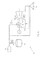
Figures 1 and2 are diagrammatic illustrations of a first embodiment of a solar thermal power system in first and second operating modes respectively; -
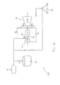
Figure 3 is a diagrammatic illustration of a second embodiment of a solar thermal power system; and -
Figure 4 is a diagrammatic illustration of a third embodiment of a solar thermal power system. - Embodiments of the present disclosure will now be described by way of example only and with reference to the accompanying drawings.
- Referring initially to
Figures 1 and2 , there is shown diagrammatically a solarthermal power system 10 including a solarreceiver steam generator 12. Although not shown in the drawings, the solarreceiver steam generator 12 comprises a solar radiation receiver mounted on top of a tower, solar radiation being reflected onto the solar radiation receiver by a heliostat field surrounding the tower. The heliostat field can be replaced by any other solar heating system such as Fresnel collectors . - The solar thermal power system includes a thermal
energy storage arrangement 14 which utilises molten salt as a sensible heat thermal energy storage fluid. Although not illustrated, in typical embodiments the thermalenergy storage arrangement 14 includes an insulated hot salt storage tank and a relatively cool salt storage tank, a first heat exchanger to transfer heat to the cool molten salt as it flows from the cool salt storage tank to the holt salt storage tank during a charging cycle, and a second heat exchanger to recover heat from the hot molten salt as it flows from the hot salt storage tank to the cool salt storage tank during a discharging cycle. - The solar
thermal power system 10 includes amultistage steam turbine 16 comprising a high pressure stage HP and intermediate and low pressure stages IP, LP downstream of the high pressure stage HP. Thesteam turbine 16 includes a highpressure turbine inlet 18 at the inlet region of the high pressure stage HP through which steam can be supplied to the high pressure stage HP for expansion through thesteam turbine 16. Superheated steam expanded through thesteam turbine 16 drives an electrical generator G to generate electrical power in a conventional manner. An air-cooledcondenser 20 is also provided. - The solar
thermal power system 10 is operated in different modes depending on the prevailing power generation requirements and the amount of solar radiation that is available. - During daylight hours, the solar
thermal power system 10 can be operated in a first operating mode (combined power generation/storage mode), as shown inFigure 1 , provided that there is a sufficient amount of solar radiation. In the first operating mode, water circulating in the solarreceiver steam generator 12 is heated by thermal energy arising from solar radiation reflected by the heliostat field onto the solar radiation receiver. This generates superheated steam, typically at a pressure in the region of 120 to 175 bar and a temperature in the region of 560°C to 590°C. In the illustrated embodiment, the generated superheated steam has a pressure of about 170 bar and a temperature of about 585°C. - In the first operating mode, a proportion of the mass flow rate of superheated steam generated by the solar
receiver steam generator 12 is supplied directly to the highpressure turbine inlet 18 for expansion through the high, intermediate and low pressure stages HP, IP, LP of thesteam turbine 16 in a conventional manner. As indicated above, expansion of the superheated steam in thesteam turbine 16 drives the electrical generator G, thereby generating electrical power. - A proportion of the mass flow rate of superheated steam generated by the solar
receiver steam generator 12 is supplied to the thermalenergy storage arrangement 14 and fed through the first heat exchanger during the charging cycle. The superheated steam is cooled in the first heat exchanger and heat is transferred from the superheated steam to the molten salt as it circulates from the cool salt storage tank to the hot salt storage tank. - In the embodiment of the first operating mode illustrated in
Figure 1 , about 50% of the mass flow rate of steam generated by the solarreceiver steam generator 12 is supplied to the highpressure turbine inlet 18 to support electrical power generation whilst the remaining 50% of the mass flow rate of steam is supplied to the thermalenergy storage arrangement 14 to heat the molten salt. These proportions can, of course, be varied as necessary by controlling the system valves. - In the first operating mode illustrated in
Figure 1 , the valves designated V1, V3, V4, V5 and V6 are open whilst the valve designated V2 is closed so that the superheated steam generated by the solarreceiver steam generator 12 flows along the path shown by the arrows. - At times when there is insufficient solar energy to directly heat the water circulating in the solar
receiver steam generator 12 to provide steam at the desired pressure and temperature for efficient operation of the solarthermal power system 10 in the first operating mode described above, the solarthermal power system 10 can be operated in a second operating mode (energy recovery mode), as shown inFigure 2 , to supply superheated steam to thesteam turbine 16. In the second operating mode, the second heat exchanger is used to recover thermal energy from hot molten salt during the discharging cycle as the hot molten salt flows from the hot salt storage tank to the cool salt storage tank. This operating mode is typically used during non-daylight hours when solar radiation is not available to generate steam in the solarreceiver steam generator 12. It can also be used during daylight hours if there is insufficient solar radiation to generate steam in the solarreceiver steam generator 12 at the desired pressure and temperature for thesteam turbine 16, for example during overcast conditions. - Due to the exergy losses discussed above in the Technical Background section of this specification, the superheated steam generated during the second operating mode by recovering thermal energy from the hot molten salt during the discharging cycle has a lower pressure and temperature than the superheated steam generated by the solar
receiver steam generator 12 during the first operating mode. In the illustrated embodiment, the steam generated by the thermalenergy storage arrangement 14 during the second operating mode of the solarthermal power system 10 has a pressure of about 80 bar and a temperature of about 360°C. The steam mass flow rate is about 45 % higer than during direct production. - In accordance with aspects of the present disclosure, the lower pressure and lower temperature steam generated during the second operating mode is injected into the intermediate stage IP of the
steam turbine 16, rather than into the high pressure stage HP via the highpressure turbine inlet 18, the intermediate stage being compatible with the lower pressure and lower temperature steam conditions during the second operating mode. The highpressure turbine inlet 18, and hence the high pressure stage HP of thesteam turbine 16, is therefore bypassed during the second operating mode. Steam is not expanded in the high pressure stage HP during the second operating mode and the high pressure stage HP does not contribute to the generation of electrical power. - As explained above, bypassing the high pressure stage HP provides steam at a higher pressure (about 80 bar) to the intermediate pressure stage IP than the steam flowing through the intermediate pressure stage IP during the first operating mode (when the pressure is about 50 bar). There is, therefore, a greater mass flow rate of steam (about 45% higher) through the intermediate pressure stage IP during the second operating mode than during the first operating mode () when the steam from the solar
receiver steam generator 12 is initially expanded in the high pressure stage HP. As a result of the increased steam mass flow rate, the power output of the intermediate pressure stage IP and also the low pressure stage LP is increased during the second operating mode, thereby providing a greater power output than would otherwise be achieved if the lower pressure and lower temperature steam was injected into the highpressure turbine inlet 18 and expanded through the high, intermediate and low pressure stages HP, IP, LP. - In the second operating mode illustrated in
Figure 2 , the valves designated V1, V2, V5 and V6 are open whilst the valves designated V3 and V4 are closed so that the superheated steam generated by the thermalenergy storage system 14 flows along the path shown by the arrows and bypasses the high pressure stage HP of thesteam turbine 16. Furthermore, the valve designated V7 is preferably open so that the high pressure stage HP is connected to thecondenser 20. This maintains the high pressure stage HP at a relatively low pressure during the second operating mode and thereby avoids excessive temperatures in the high pressure stage HP which is running empty. - Referring now to
Figure 3 , there is shown a second embodiment of a solarthermal power system 110 which is similar to the solarthermal power system 10 illustrated inFigures 1 and2 and in which corresponding components are identified using the same references. - The solar
thermal power system 110 ofFigure 3 operates in the same manner as the solarthermal power system 10 ofFigures 1 and2 during the first operating mode. During the second operating mode, the valve V3 is, however, partially open to allow a small cooling flow of steam generated by recovering thermal energy from the molten salt to be supplied to the high pressure stage HP of thesteam turbine 16 through the highpressure turbine inlet 18. The solarthermal power system 110 includes anelectrical superheater 22 which heats the cooling flow during the second operating mode to prevent excessive cooling of the high pressure stage HP. The cooling flow supplied to the high pressure stage HP does not contribute to the power output of thesteam turbine 16. The valve V7 is open during the second operating mode so that condensed steam from the high pressure stage HP can be fed to thecondenser 22. - Referring now to
Figure 4 , there is shown a third embodiment of a solarthermal power system 210 which is similar to the solarthermal power system 10 illustrated inFigures 1 and2 and in which corresponding components are identified using the same references. - The solar
thermal power system 210 includes aclutch device 24 which can be can be used during the second operating mode to decouple the high pressure stage HP of thesteam turbine 16 from the electrical generator G and the intermediate and low pressure stages IP, LP. Accordingly, the high pressure stage HP does not rotate during the second operating mode and it is thus not necessary to connect the high pressure stage HP to thecondenser 20 to maintain it at a low pressure as described above with reference toFigure 2 or to provide a cooling flow to thehigh pressure stage 20 as described above with reference toFigure 3 . - In principle an increased mass flow can also be achieved by means of having a parallel turbine in place.
- Although exemplary embodiments have been described in the preceding paragraphs, it should be understood that various modifications may be made to those embodiments without departing from the scope of the appended claims. Thus, the breadth and scope of the claims should not be limited to the above-described exemplary embodiments. Each feature disclosed in the specification, including the claims and drawings, may be replaced by alternative features serving the same, equivalent or similar purposes, unless expressly stated otherwise.
- For example, the steam pressures and temperatures at different points in the solar thermal power system are provided for illustrative purposes only. It should be understood that other steam pressures and temperatures are entirely within the scope of the appended claims.
- Although the thermal energy storage fluid is typically a molten salt, other thermal energy storage fluids having a high specific heat capacity could be employed. As well other thermal energy storage systems based on other storage media (e.g. solid media like concrete) could be employed.
- Unless the context clearly requires otherwise, throughout the description and the claims, the words "comprise", "comprising", and the like, are to be construed in an inclusive as opposed to an exclusive or exhaustive sense; that is to say, in the sense of "including, but not limited to".
Claims (15)
- A solar thermal power system (10, 110, 210) comprising a solar receiver steam generator (12), a thermal energy storage arrangement (14) including a thermal energy storage fluid, and a multistage steam turbine (16) for driving an electrical generator (G) to produce electrical power, wherein the solar thermal power system has:a first operating mode in which steam is generated by the solar receiver steam generator (12) and is supplied to the thermal energy storage arrangement (14) to heat the thermal energy storage fluid and to a high pressure turbine inlet (18) of the multistage steam turbine (16) to drive the steam turbine; anda second operating mode in which steam is generated by recovering stored thermal energy from the thermal energy storage fluid, the steam generated during the second operating mode having a storage discharge pressure and storage discharge temperature lower than the pressure and temperature of the steam generated during the first operating mode, characterised in that the lower pressure and lower temperature steam is injected into the multistage steam turbine (16) to drive the steam turbine at a turbine stage downstream of the high pressure turbine inlet (18) where the storage discharge pressure exceeds the pressure present in the turbine stage during the first operational mode and hence increase the mass flow through the turbine compared to the mass flow during the first operational mode.
- A solar thermal power system according to claim 1, wherein the high pressure turbine inlet (18) is provided at an inlet region of a high pressure stage (HP) of the multistage steam turbine (16).
- A solar thermal power system according to claim 2, wherein the multistage steam turbine (16) includes one or more lower pressure stages downstream of the high pressure stage (HP) and the steam at storage discharge pressure and storage discharge temperature generated during the second operating mode is injected into a turbine stage having a lower pressure stage during the first operational mode to drive the steam turbine.
- A solar thermal power system according to claim 3, wherein the multistage steam turbine (16) includes an intermediate pressure stage (IP) and a low pressure stage (LP) and the steam at storage discharge pressure and storage discharge temperature generated during the second operating mode is injected into the intermediate pressure stage (IP) to drive the steam turbine.
- A solar thermal power system according to claim 2, wherein the high pressure stage (HP) includes a first section and a second section downstream of the first section and the steam at storage discharge pressure and storage discharge temperature am generated during the second operating mode is injected into the second section of the high pressure stage (HP).
- A solar thermal power system according to any preceding claim, wherein the solar thermal power system is arranged to supply a proportion of the steam at storage discharge pressure and storage discharge temperature generated by the thermal energy storage arrangement (14) during the second operating mode to the high pressure turbine inlet (18) to act as a cooling flow for the high pressure region of the steam turbine (16).
- A solar thermal power system according to claim 6, further including an electrical superheater (22) to heat the cooling flow prior to injection into the high pressure turbine inlet (18).
- A solar thermal power system according to any of claims 1 to 5, wherein the solar thermal power system includes a condenser (20) which is connected to the high pressure region of the steam turbine (16) during the second operating mode to maintain the high pressure region at a low pressure.
- A solar thermal power system according to any of claims 1 to 5, wherein the solar thermal power system includes a clutch device (24) to decouple the high pressure region of the steam turbine (16) and thereby prevent its rotation during the second operating mode.
- A method for operating a solar thermal power system (10, 110, 210), the system comprising a solar receiver steam generator (12), a thermal energy storage arrangement (14) including a thermal energy storage fluid, and a multistage steam turbine (16) for driving an electrical generator (G) to produce electrical power, wherein the solar thermal power system has:a first operating mode in which steam is generated by the solar receiver steam generator (12); anda second operating mode in which steam is generated by recovering stored thermal energy from the thermal energy storage fluid, the storage steam generated during the second operating mode having a lower pressure and lower temperature than the steam generated during the first operating mode;wherein the operating method comprises supplying the steam generated during the first operating mode to the thermal energy storage arrangement (14) to heat the thermal energy storage fluid and to a high pressure turbine inlet (18) of the multistage steam turbine (16) to drive the steam turbine;characterised in that the operating method comprises injecting the storage steam generated during the second operating mode into the multistage steam turbine (16) at a turbine stage downstream of the high pressure turbine inlet (18) where the storage discharge steam pressure exceeds the pressure present in the turbine stage during the first operational mode and hence increase the mass flow through the turbine compared to the mass flow during the first operational mode.
- An operating method according to claim 10, wherein the high pressure turbine inlet (18) is provided at an inlet region of a high pressure stage (HP) of the multistage steam turbine (16).
- An operating method according to claim 11, wherein the multistage steam turbine (16) includes one or more lower pressure stages downstream of the high pressure stage (HP) and the operating method comprises injecting the steam at storage discharge pressure and storage discharge temperature generated during the second operating mode into a lower pressure stage to drive the steam turbine.
- An operating method according to claim 12, wherein the multistage steam turbine (16) includes an intermediate pressure stage (IP) and a low pressure stage (LP) and the operating method comprises injecting the lower pressure and lower temperature steam generated during the second operating mode into the intermediate pressure stage (IP) to drive the steam turbine.
- An operating method according to claim 11, wherein the high pressure stage (HP) includes a first section and a second section downstream of the first section and the operating method comprises injecting the steam at storage discharge pressure and storage discharge temperature generated during the second operating mode into the second section of the high pressure stage (HP).
- An operating method according to any of claims 10 to 14, further comprising:(a) supplying a proportion of the lower pressure and lower temperature steam to the high pressure turbine inlet (18) during the second operating mode to act as a cooling flow for the high pressure region of the steam turbine (16) and heating the cooling flow of steam prior to injection into the high pressure turbine inlet (18); or(b) maintaining the high pressure region of the steam turbine (16) at a low pressure during the second operating mode; or(c) decoupling the high pressure region of the steam turbine (16) during the second operating mode to prevent its rotation.
Priority Applications (7)
| Application Number | Priority Date | Filing Date | Title |
|---|---|---|---|
| PT121629067T PT2647841T (en) | 2012-04-02 | 2012-04-02 | Solar thermal power system |
| ES12162906T ES2835740T3 (en) | 2012-04-02 | 2012-04-02 | Solar thermal energy system |
| EP12162906.7A EP2647841B1 (en) | 2012-04-02 | 2012-04-02 | Solar thermal power system |
| TNP2013000116A TN2013000116A1 (en) | 2012-04-02 | 2013-03-18 | Solar thermal power system |
| US13/855,297 US9638173B2 (en) | 2012-04-02 | 2013-04-02 | Solar thermal power system |
| CN201310112008.2A CN103362762B (en) | 2012-04-02 | 2013-04-02 | Solar heat electric system |
| CY20201101197T CY1123828T1 (en) | 2012-04-02 | 2020-12-18 | SOLAR THERMAL ENERGY SYSTEM |
Applications Claiming Priority (1)
| Application Number | Priority Date | Filing Date | Title |
|---|---|---|---|
| EP12162906.7A EP2647841B1 (en) | 2012-04-02 | 2012-04-02 | Solar thermal power system |
Publications (2)
| Publication Number | Publication Date |
|---|---|
| EP2647841A1 true EP2647841A1 (en) | 2013-10-09 |
| EP2647841B1 EP2647841B1 (en) | 2020-09-23 |
Family
ID=46044365
Family Applications (1)
| Application Number | Title | Priority Date | Filing Date |
|---|---|---|---|
| EP12162906.7A Active EP2647841B1 (en) | 2012-04-02 | 2012-04-02 | Solar thermal power system |
Country Status (7)
| Country | Link |
|---|---|
| US (1) | US9638173B2 (en) |
| EP (1) | EP2647841B1 (en) |
| CN (1) | CN103362762B (en) |
| CY (1) | CY1123828T1 (en) |
| ES (1) | ES2835740T3 (en) |
| PT (1) | PT2647841T (en) |
| TN (1) | TN2013000116A1 (en) |
Cited By (3)
| Publication number | Priority date | Publication date | Assignee | Title |
|---|---|---|---|---|
| US20150082791A1 (en) * | 2013-09-26 | 2015-03-26 | General Electric Company | Steam turbine system with steam turbine clutch |
| EP2944812A1 (en) * | 2014-05-15 | 2015-11-18 | Kabushiki Kaisha Kobe Seiko Sho (Kobe Steel, Ltd.) | Thermal energy recovery device and control method |
| EP3056695A1 (en) * | 2015-02-10 | 2016-08-17 | General Electric Technology GmbH | Single shaft combined cycle power plant shaft arrangement |
Families Citing this family (13)
| Publication number | Priority date | Publication date | Assignee | Title |
|---|---|---|---|---|
| WO2012093354A2 (en) * | 2011-01-03 | 2012-07-12 | Brightsource Industries (Israel) Ltd. | Thermal storage system and methods |
| US9541071B2 (en) | 2012-12-04 | 2017-01-10 | Brightsource Industries (Israel) Ltd. | Concentrated solar power plant with independent superheater |
| ITFI20120273A1 (en) * | 2012-12-07 | 2014-06-08 | Nuovo Pignone Srl | "A CONCENTRATED SOLAR THERMAL POWER PLANT AND METHOD" |
| US20150128558A1 (en) * | 2013-11-11 | 2015-05-14 | Bechtel Power Corporation | Solar fired combined cycle with supercritical turbine |
| PL2930422T3 (en) * | 2014-04-08 | 2016-12-30 | Method to operate a steam turbine, steam turbine and concentrated solar power plant | |
| US10323543B2 (en) * | 2014-07-28 | 2019-06-18 | Third Power, LLC | Conversion of power plants to energy storage resources |
| US10254012B2 (en) * | 2015-09-08 | 2019-04-09 | Peter B. Choi | Sensible thermal energy storage (STES) systems |
| CN105888752B (en) * | 2015-09-25 | 2017-08-25 | 浙江秀舟热电有限公司 | Power generation system optimal control method |
| CN105298568B (en) * | 2015-10-07 | 2017-01-18 | 京蓝能科技术有限公司 | Power generation system and control method thereof |
| DE102016214447B4 (en) * | 2016-08-04 | 2020-12-24 | Siemens Aktiengesellschaft | Power plant with phase change material heat storage and method for operating a power plant with phase change material heat storage |
| EP3730749A1 (en) * | 2019-04-24 | 2020-10-28 | Siemens Gamesa Renewable Energy GmbH & Co. KG | Effective charging process of an energy conversion system |
| US11661857B2 (en) | 2020-06-16 | 2023-05-30 | Cyrq Energy, Inc. | Electricity generating systems with thermal energy storage coupled superheaters |
| CN114992619B (en) * | 2022-05-23 | 2023-11-03 | 西安热工研究院有限公司 | Combined heat and power generation unit based on fused salt heat storage |
Citations (3)
| Publication number | Priority date | Publication date | Assignee | Title |
|---|---|---|---|---|
| US4164123A (en) * | 1976-08-25 | 1979-08-14 | Smith Otto J M | Solar thermal electric power plant |
| JP2004340093A (en) * | 2003-05-19 | 2004-12-02 | Hideo Tamai | Solar heat power generator |
| WO2011119413A2 (en) * | 2010-03-22 | 2011-09-29 | Skibo Systems Llc | Systems and methods for integrating concentrated solar thermal and geothermal power plants using multistage thermal energy storage |
Family Cites Families (4)
| Publication number | Priority date | Publication date | Assignee | Title |
|---|---|---|---|---|
| CN101413719B (en) * | 2007-10-17 | 2011-10-12 | 中国科学院工程热物理研究所 | Tower type solar heat power generation system with double-stage thermal storage |
| US8544273B2 (en) | 2008-09-17 | 2013-10-01 | Siemens Concentrated Solar Power Ltd. | Solar thermal power plant |
| US20120255300A1 (en) | 2009-12-22 | 2012-10-11 | Birnbaum Juergen | Solar thermal power plant and method for operating a solar thermal power plant |
| CN101876299B (en) * | 2010-05-24 | 2012-06-20 | 北京京仪集团有限责任公司 | Method and system for combing solar energy thermal power generation with biomass power generation |
-
2012
- 2012-04-02 ES ES12162906T patent/ES2835740T3/en active Active
- 2012-04-02 PT PT121629067T patent/PT2647841T/en unknown
- 2012-04-02 EP EP12162906.7A patent/EP2647841B1/en active Active
-
2013
- 2013-03-18 TN TNP2013000116A patent/TN2013000116A1/en unknown
- 2013-04-02 CN CN201310112008.2A patent/CN103362762B/en active Active
- 2013-04-02 US US13/855,297 patent/US9638173B2/en active Active
-
2020
- 2020-12-18 CY CY20201101197T patent/CY1123828T1/en unknown
Patent Citations (3)
| Publication number | Priority date | Publication date | Assignee | Title |
|---|---|---|---|---|
| US4164123A (en) * | 1976-08-25 | 1979-08-14 | Smith Otto J M | Solar thermal electric power plant |
| JP2004340093A (en) * | 2003-05-19 | 2004-12-02 | Hideo Tamai | Solar heat power generator |
| WO2011119413A2 (en) * | 2010-03-22 | 2011-09-29 | Skibo Systems Llc | Systems and methods for integrating concentrated solar thermal and geothermal power plants using multistage thermal energy storage |
Cited By (5)
| Publication number | Priority date | Publication date | Assignee | Title |
|---|---|---|---|---|
| US20150082791A1 (en) * | 2013-09-26 | 2015-03-26 | General Electric Company | Steam turbine system with steam turbine clutch |
| EP2944812A1 (en) * | 2014-05-15 | 2015-11-18 | Kabushiki Kaisha Kobe Seiko Sho (Kobe Steel, Ltd.) | Thermal energy recovery device and control method |
| US9797272B2 (en) | 2014-05-15 | 2017-10-24 | Kobe Steel, Ltd. | Thermal energy recovery device and control method |
| EP3056695A1 (en) * | 2015-02-10 | 2016-08-17 | General Electric Technology GmbH | Single shaft combined cycle power plant shaft arrangement |
| US10544706B2 (en) | 2015-02-10 | 2020-01-28 | General Electric Technology Gmbh | Single shaft combined cycle power plant shaft arrangement |
Also Published As
| Publication number | Publication date |
|---|---|
| PT2647841T (en) | 2020-12-09 |
| CY1123828T1 (en) | 2022-03-24 |
| US20130255254A1 (en) | 2013-10-03 |
| CN103362762A (en) | 2013-10-23 |
| ES2835740T3 (en) | 2021-06-23 |
| TN2013000116A1 (en) | 2014-06-25 |
| CN103362762B (en) | 2015-09-23 |
| EP2647841B1 (en) | 2020-09-23 |
| US9638173B2 (en) | 2017-05-02 |
Similar Documents
| Publication | Publication Date | Title |
|---|---|---|
| EP2647841B1 (en) | Solar thermal power system | |
| EP2718565B1 (en) | Solar thermal power plant | |
| US10247174B2 (en) | Solar thermal power generation system and solar thermal power generation method | |
| US9322295B2 (en) | Thermal energy storage unit with steam and gas turbine system | |
| US7685820B2 (en) | Supercritical CO2 turbine for use in solar power plants | |
| US8567196B2 (en) | Steam turbine power plant and operating method thereof | |
| AU2008228211B2 (en) | Method and device for intermediate superheating in solar direct evaporation in a solar-thermal power plant | |
| US8938966B2 (en) | Storage of electrical energy with thermal storage and return through a thermodynamic cycle | |
| CN102483263B (en) | Vapour only cycling of heat transfer fluid for the thermal storage of solar energy | |
| US20120216536A1 (en) | Supercritical carbon dioxide power cycle configuration for use in concentrating solar power systems | |
| US20120151917A1 (en) | Steam power plant having solar collectors | |
| KR101660923B1 (en) | Steam turbine plant | |
| JP2014092086A (en) | Solar heat power plant, and solar heat storage and radiation apparatus | |
| US9957954B2 (en) | Solar thermal power generation system | |
| US20130047611A1 (en) | Solar power plant part of a solar thermal power plant and solar thermal power plant provided with solar collector surfaces for a heat transfer medium and working medium | |
| US20080034757A1 (en) | Method and system integrating solar heat into a regenerative rankine cycle | |
| WO2013064425A1 (en) | Solar power system and method of operating a solar power system | |
| US20190323384A1 (en) | Boilor plant and method for operating the same | |
| KR101399428B1 (en) | Safety system of orc generation system | |
| KR20220148907A (en) | Renewable Power Generation Systems and Methods | |
| US9581051B2 (en) | Power generation plant and method of operating a power generation plant | |
| JP2001055906A (en) | Combined power generating method and system therefor | |
| Belverato et al. | Part-Load of Steam Rankine Cycles for Solar Salts-Based Concentrating Solar Power Plants | |
| JP2015161284A (en) | control system and heat supply method | |
| US9634169B1 (en) | Hybrid solar concentrator utilizing a dielectric spectrum splitter |
Legal Events
| Date | Code | Title | Description |
|---|---|---|---|
| PUAI | Public reference made under article 153(3) epc to a published international application that has entered the european phase |
Free format text: ORIGINAL CODE: 0009012 |
|
| AK | Designated contracting states |
Kind code of ref document: A1 Designated state(s): AL AT BE BG CH CY CZ DE DK EE ES FI FR GB GR HR HU IE IS IT LI LT LU LV MC MK MT NL NO PL PT RO RS SE SI SK SM TR |
|
| AX | Request for extension of the european patent |
Extension state: BA ME |
|
| 17P | Request for examination filed |
Effective date: 20131023 |
|
| RBV | Designated contracting states (corrected) |
Designated state(s): AL AT BE BG CH CY CZ DE DK EE ES FI FR GB GR HR HU IE IS IT LI LT LU LV MC MK MT NL NO PL PT RO RS SE SI SK SM TR |
|
| RAP1 | Party data changed (applicant data changed or rights of an application transferred) |
Owner name: GENERAL ELECTRIC TECHNOLOGY GMBH |
|
| STAA | Information on the status of an ep patent application or granted ep patent |
Free format text: STATUS: EXAMINATION IS IN PROGRESS |
|
| 17Q | First examination report despatched |
Effective date: 20190726 |
|
| GRAP | Despatch of communication of intention to grant a patent |
Free format text: ORIGINAL CODE: EPIDOSNIGR1 |
|
| STAA | Information on the status of an ep patent application or granted ep patent |
Free format text: STATUS: GRANT OF PATENT IS INTENDED |
|
| INTG | Intention to grant announced |
Effective date: 20200422 |
|
| GRAS | Grant fee paid |
Free format text: ORIGINAL CODE: EPIDOSNIGR3 |
|
| GRAA | (expected) grant |
Free format text: ORIGINAL CODE: 0009210 |
|
| STAA | Information on the status of an ep patent application or granted ep patent |
Free format text: STATUS: THE PATENT HAS BEEN GRANTED |
|
| AK | Designated contracting states |
Kind code of ref document: B1 Designated state(s): AL AT BE BG CH CY CZ DE DK EE ES FI FR GB GR HR HU IE IS IT LI LT LU LV MC MK MT NL NO PL PT RO RS SE SI SK SM TR |
|
| REG | Reference to a national code |
Ref country code: GB Ref legal event code: FG4D |
|
| REG | Reference to a national code |
Ref country code: CH Ref legal event code: EP |
|
| REG | Reference to a national code |
Ref country code: IE Ref legal event code: FG4D |
|
| REG | Reference to a national code |
Ref country code: AT Ref legal event code: REF Ref document number: 1316627 Country of ref document: AT Kind code of ref document: T Effective date: 20201015 Ref country code: DE Ref legal event code: R096 Ref document number: 602012072415 Country of ref document: DE |
|
| REG | Reference to a national code |
Ref country code: PT Ref legal event code: SC4A Ref document number: 2647841 Country of ref document: PT Date of ref document: 20201209 Kind code of ref document: T Free format text: AVAILABILITY OF NATIONAL TRANSLATION Effective date: 20201203 |
|
| PG25 | Lapsed in a contracting state [announced via postgrant information from national office to epo] |
Ref country code: HR Free format text: LAPSE BECAUSE OF FAILURE TO SUBMIT A TRANSLATION OF THE DESCRIPTION OR TO PAY THE FEE WITHIN THE PRESCRIBED TIME-LIMIT Effective date: 20200923 Ref country code: FI Free format text: LAPSE BECAUSE OF FAILURE TO SUBMIT A TRANSLATION OF THE DESCRIPTION OR TO PAY THE FEE WITHIN THE PRESCRIBED TIME-LIMIT Effective date: 20200923 Ref country code: BG Free format text: LAPSE BECAUSE OF FAILURE TO SUBMIT A TRANSLATION OF THE DESCRIPTION OR TO PAY THE FEE WITHIN THE PRESCRIBED TIME-LIMIT Effective date: 20201223 Ref country code: SE Free format text: LAPSE BECAUSE OF FAILURE TO SUBMIT A TRANSLATION OF THE DESCRIPTION OR TO PAY THE FEE WITHIN THE PRESCRIBED TIME-LIMIT Effective date: 20200923 Ref country code: NO Free format text: LAPSE BECAUSE OF FAILURE TO SUBMIT A TRANSLATION OF THE DESCRIPTION OR TO PAY THE FEE WITHIN THE PRESCRIBED TIME-LIMIT Effective date: 20201223 |
|
| REG | Reference to a national code |
Ref country code: AT Ref legal event code: MK05 Ref document number: 1316627 Country of ref document: AT Kind code of ref document: T Effective date: 20200923 |
|
| PG25 | Lapsed in a contracting state [announced via postgrant information from national office to epo] |
Ref country code: RS Free format text: LAPSE BECAUSE OF FAILURE TO SUBMIT A TRANSLATION OF THE DESCRIPTION OR TO PAY THE FEE WITHIN THE PRESCRIBED TIME-LIMIT Effective date: 20200923 Ref country code: LV Free format text: LAPSE BECAUSE OF FAILURE TO SUBMIT A TRANSLATION OF THE DESCRIPTION OR TO PAY THE FEE WITHIN THE PRESCRIBED TIME-LIMIT Effective date: 20200923 |
|
| REG | Reference to a national code |
Ref country code: NL Ref legal event code: MP Effective date: 20200923 |
|
| REG | Reference to a national code |
Ref country code: LT Ref legal event code: MG4D |
|
| PG25 | Lapsed in a contracting state [announced via postgrant information from national office to epo] |
Ref country code: EE Free format text: LAPSE BECAUSE OF FAILURE TO SUBMIT A TRANSLATION OF THE DESCRIPTION OR TO PAY THE FEE WITHIN THE PRESCRIBED TIME-LIMIT Effective date: 20200923 Ref country code: CZ Free format text: LAPSE BECAUSE OF FAILURE TO SUBMIT A TRANSLATION OF THE DESCRIPTION OR TO PAY THE FEE WITHIN THE PRESCRIBED TIME-LIMIT Effective date: 20200923 Ref country code: LT Free format text: LAPSE BECAUSE OF FAILURE TO SUBMIT A TRANSLATION OF THE DESCRIPTION OR TO PAY THE FEE WITHIN THE PRESCRIBED TIME-LIMIT Effective date: 20200923 Ref country code: NL Free format text: LAPSE BECAUSE OF FAILURE TO SUBMIT A TRANSLATION OF THE DESCRIPTION OR TO PAY THE FEE WITHIN THE PRESCRIBED TIME-LIMIT Effective date: 20200923 Ref country code: SM Free format text: LAPSE BECAUSE OF FAILURE TO SUBMIT A TRANSLATION OF THE DESCRIPTION OR TO PAY THE FEE WITHIN THE PRESCRIBED TIME-LIMIT Effective date: 20200923 Ref country code: RO Free format text: LAPSE BECAUSE OF FAILURE TO SUBMIT A TRANSLATION OF THE DESCRIPTION OR TO PAY THE FEE WITHIN THE PRESCRIBED TIME-LIMIT Effective date: 20200923 |
|
| PG25 | Lapsed in a contracting state [announced via postgrant information from national office to epo] |
Ref country code: PL Free format text: LAPSE BECAUSE OF FAILURE TO SUBMIT A TRANSLATION OF THE DESCRIPTION OR TO PAY THE FEE WITHIN THE PRESCRIBED TIME-LIMIT Effective date: 20200923 Ref country code: IS Free format text: LAPSE BECAUSE OF FAILURE TO SUBMIT A TRANSLATION OF THE DESCRIPTION OR TO PAY THE FEE WITHIN THE PRESCRIBED TIME-LIMIT Effective date: 20210123 Ref country code: AT Free format text: LAPSE BECAUSE OF FAILURE TO SUBMIT A TRANSLATION OF THE DESCRIPTION OR TO PAY THE FEE WITHIN THE PRESCRIBED TIME-LIMIT Effective date: 20200923 Ref country code: AL Free format text: LAPSE BECAUSE OF FAILURE TO SUBMIT A TRANSLATION OF THE DESCRIPTION OR TO PAY THE FEE WITHIN THE PRESCRIBED TIME-LIMIT Effective date: 20200923 |
|
| REG | Reference to a national code |
Ref country code: ES Ref legal event code: FG2A Ref document number: 2835740 Country of ref document: ES Kind code of ref document: T3 Effective date: 20210623 |
|
| REG | Reference to a national code |
Ref country code: DE Ref legal event code: R097 Ref document number: 602012072415 Country of ref document: DE |
|
| PG25 | Lapsed in a contracting state [announced via postgrant information from national office to epo] |
Ref country code: SK Free format text: LAPSE BECAUSE OF FAILURE TO SUBMIT A TRANSLATION OF THE DESCRIPTION OR TO PAY THE FEE WITHIN THE PRESCRIBED TIME-LIMIT Effective date: 20200923 |
|
| PLBE | No opposition filed within time limit |
Free format text: ORIGINAL CODE: 0009261 |
|
| STAA | Information on the status of an ep patent application or granted ep patent |
Free format text: STATUS: NO OPPOSITION FILED WITHIN TIME LIMIT |
|
| PG25 | Lapsed in a contracting state [announced via postgrant information from national office to epo] |
Ref country code: SI Free format text: LAPSE BECAUSE OF FAILURE TO SUBMIT A TRANSLATION OF THE DESCRIPTION OR TO PAY THE FEE WITHIN THE PRESCRIBED TIME-LIMIT Effective date: 20200923 Ref country code: DK Free format text: LAPSE BECAUSE OF FAILURE TO SUBMIT A TRANSLATION OF THE DESCRIPTION OR TO PAY THE FEE WITHIN THE PRESCRIBED TIME-LIMIT Effective date: 20200923 |
|
| 26N | No opposition filed |
Effective date: 20210624 |
|
| REG | Reference to a national code |
Ref country code: DE Ref legal event code: R119 Ref document number: 602012072415 Country of ref document: DE |
|
| PG25 | Lapsed in a contracting state [announced via postgrant information from national office to epo] |
Ref country code: MC Free format text: LAPSE BECAUSE OF FAILURE TO SUBMIT A TRANSLATION OF THE DESCRIPTION OR TO PAY THE FEE WITHIN THE PRESCRIBED TIME-LIMIT Effective date: 20200923 |
|
| GBPC | Gb: european patent ceased through non-payment of renewal fee |
Effective date: 20210402 |
|
| PG25 | Lapsed in a contracting state [announced via postgrant information from national office to epo] |
Ref country code: LU Free format text: LAPSE BECAUSE OF NON-PAYMENT OF DUE FEES Effective date: 20210402 |
|
| REG | Reference to a national code |
Ref country code: BE Ref legal event code: MM Effective date: 20210430 |
|
| PG25 | Lapsed in a contracting state [announced via postgrant information from national office to epo] |
Ref country code: CH Free format text: LAPSE BECAUSE OF NON-PAYMENT OF DUE FEES Effective date: 20210430 Ref country code: LI Free format text: LAPSE BECAUSE OF NON-PAYMENT OF DUE FEES Effective date: 20210430 Ref country code: GB Free format text: LAPSE BECAUSE OF NON-PAYMENT OF DUE FEES Effective date: 20210402 Ref country code: FR Free format text: LAPSE BECAUSE OF NON-PAYMENT OF DUE FEES Effective date: 20210430 Ref country code: DE Free format text: LAPSE BECAUSE OF NON-PAYMENT OF DUE FEES Effective date: 20211103 |
|
| PG25 | Lapsed in a contracting state [announced via postgrant information from national office to epo] |
Ref country code: IE Free format text: LAPSE BECAUSE OF NON-PAYMENT OF DUE FEES Effective date: 20210402 |
|
| PG25 | Lapsed in a contracting state [announced via postgrant information from national office to epo] |
Ref country code: IS Free format text: LAPSE BECAUSE OF FAILURE TO SUBMIT A TRANSLATION OF THE DESCRIPTION OR TO PAY THE FEE WITHIN THE PRESCRIBED TIME-LIMIT Effective date: 20210123 |
|
| PG25 | Lapsed in a contracting state [announced via postgrant information from national office to epo] |
Ref country code: BE Free format text: LAPSE BECAUSE OF NON-PAYMENT OF DUE FEES Effective date: 20210430 |
|
| PG25 | Lapsed in a contracting state [announced via postgrant information from national office to epo] |
Ref country code: HU Free format text: LAPSE BECAUSE OF FAILURE TO SUBMIT A TRANSLATION OF THE DESCRIPTION OR TO PAY THE FEE WITHIN THE PRESCRIBED TIME-LIMIT; INVALID AB INITIO Effective date: 20120402 |
|
| PGFP | Annual fee paid to national office [announced via postgrant information from national office to epo] |
Ref country code: TR Payment date: 20230322 Year of fee payment: 12 Ref country code: IT Payment date: 20230322 Year of fee payment: 12 |
|
| P01 | Opt-out of the competence of the unified patent court (upc) registered |
Effective date: 20230523 |
|
| PGFP | Annual fee paid to national office [announced via postgrant information from national office to epo] |
Ref country code: ES Payment date: 20230502 Year of fee payment: 12 Ref country code: CY Payment date: 20230322 Year of fee payment: 12 |
|
| PGFP | Annual fee paid to national office [announced via postgrant information from national office to epo] |
Ref country code: GR Payment date: 20240322 Year of fee payment: 13 |
|
| PG25 | Lapsed in a contracting state [announced via postgrant information from national office to epo] |
Ref country code: MK Free format text: LAPSE BECAUSE OF FAILURE TO SUBMIT A TRANSLATION OF THE DESCRIPTION OR TO PAY THE FEE WITHIN THE PRESCRIBED TIME-LIMIT Effective date: 20200923 |
|
| PGFP | Annual fee paid to national office [announced via postgrant information from national office to epo] |
Ref country code: PT Payment date: 20240321 Year of fee payment: 13 |