EP2641027B1 - Device and method for controlling opening of a valve in an hvac system - Google Patents
Device and method for controlling opening of a valve in an hvac system Download PDFInfo
- Publication number
- EP2641027B1 EP2641027B1 EP11773661.1A EP11773661A EP2641027B1 EP 2641027 B1 EP2641027 B1 EP 2641027B1 EP 11773661 A EP11773661 A EP 11773661A EP 2641027 B1 EP2641027 B1 EP 2641027B1
- Authority
- EP
- European Patent Office
- Prior art keywords
- energy
- valve
- flow
- per
- opening
- Prior art date
- Legal status (The legal status is an assumption and is not a legal conclusion. Google has not performed a legal analysis and makes no representation as to the accuracy of the status listed.)
- Active
Links
- 238000000034 method Methods 0.000 title claims description 18
- 239000012530 fluid Substances 0.000 claims description 52
- 230000001276 controlling effect Effects 0.000 claims description 33
- 238000005259 measurement Methods 0.000 claims description 12
- 230000001105 regulatory effect Effects 0.000 claims description 4
- 230000003247 decreasing effect Effects 0.000 claims description 3
- 102220293834 rs1553603207 Human genes 0.000 claims description 2
- 102220076183 rs796052896 Human genes 0.000 claims description 2
- 238000010586 diagram Methods 0.000 description 11
- 238000010438 heat treatment Methods 0.000 description 6
- 238000004590 computer program Methods 0.000 description 5
- 238000001816 cooling Methods 0.000 description 5
- 238000001595 flow curve Methods 0.000 description 5
- 102220559234 Voltage-dependent L-type calcium channel subunit alpha-1C_S30H_mutation Human genes 0.000 description 2
- 102220358403 c.89C>G Human genes 0.000 description 2
- 230000006870 function Effects 0.000 description 2
- 238000005070 sampling Methods 0.000 description 2
- 238000004378 air conditioning Methods 0.000 description 1
- 230000005540 biological transmission Effects 0.000 description 1
- 239000002826 coolant Substances 0.000 description 1
- 230000001419 dependent effect Effects 0.000 description 1
- 238000009434 installation Methods 0.000 description 1
- 239000007788 liquid Substances 0.000 description 1
- 238000005457 optimization Methods 0.000 description 1
- XLYOFNOQVPJJNP-UHFFFAOYSA-N water Substances O XLYOFNOQVPJJNP-UHFFFAOYSA-N 0.000 description 1
Images


Classifications
-
- F—MECHANICAL ENGINEERING; LIGHTING; HEATING; WEAPONS; BLASTING
- F24—HEATING; RANGES; VENTILATING
- F24F—AIR-CONDITIONING; AIR-HUMIDIFICATION; VENTILATION; USE OF AIR CURRENTS FOR SCREENING
- F24F11/00—Control or safety arrangements
- F24F11/70—Control systems characterised by their outputs; Constructional details thereof
- F24F11/80—Control systems characterised by their outputs; Constructional details thereof for controlling the temperature of the supplied air
- F24F11/83—Control systems characterised by their outputs; Constructional details thereof for controlling the temperature of the supplied air by controlling the supply of heat-exchange fluids to heat-exchangers
- F24F11/84—Control systems characterised by their outputs; Constructional details thereof for controlling the temperature of the supplied air by controlling the supply of heat-exchange fluids to heat-exchangers using valves
-
- F—MECHANICAL ENGINEERING; LIGHTING; HEATING; WEAPONS; BLASTING
- F24—HEATING; RANGES; VENTILATING
- F24F—AIR-CONDITIONING; AIR-HUMIDIFICATION; VENTILATION; USE OF AIR CURRENTS FOR SCREENING
- F24F11/00—Control or safety arrangements
- F24F11/70—Control systems characterised by their outputs; Constructional details thereof
- F24F11/72—Control systems characterised by their outputs; Constructional details thereof for controlling the supply of treated air, e.g. its pressure
- F24F11/74—Control systems characterised by their outputs; Constructional details thereof for controlling the supply of treated air, e.g. its pressure for controlling air flow rate or air velocity
-
- F—MECHANICAL ENGINEERING; LIGHTING; HEATING; WEAPONS; BLASTING
- F24—HEATING; RANGES; VENTILATING
- F24F—AIR-CONDITIONING; AIR-HUMIDIFICATION; VENTILATION; USE OF AIR CURRENTS FOR SCREENING
- F24F11/00—Control or safety arrangements
- F24F11/70—Control systems characterised by their outputs; Constructional details thereof
- F24F11/80—Control systems characterised by their outputs; Constructional details thereof for controlling the temperature of the supplied air
- F24F11/83—Control systems characterised by their outputs; Constructional details thereof for controlling the temperature of the supplied air by controlling the supply of heat-exchange fluids to heat-exchangers
-
- F—MECHANICAL ENGINEERING; LIGHTING; HEATING; WEAPONS; BLASTING
- F24—HEATING; RANGES; VENTILATING
- F24F—AIR-CONDITIONING; AIR-HUMIDIFICATION; VENTILATION; USE OF AIR CURRENTS FOR SCREENING
- F24F3/00—Air-conditioning systems in which conditioned primary air is supplied from one or more central stations to distributing units in the rooms or spaces where it may receive secondary treatment; Apparatus specially designed for such systems
- F24F3/06—Air-conditioning systems in which conditioned primary air is supplied from one or more central stations to distributing units in the rooms or spaces where it may receive secondary treatment; Apparatus specially designed for such systems characterised by the arrangements for the supply of heat-exchange fluid for the subsequent treatment of primary air in the room units
Definitions
- the present invention relates to a device and a method for controlling opening of a valve in a Heating, Ventilating and Air Conditioning (HVAC) system. Specifically, the present invention relates to a method and a control device for controlling the opening of a valve in an HVAC system to regulate the flow of a fluid through a thermal energy exchanger of the HVAC system and to thereby adjust the amount of energy exchanged by the thermal energy exchanger.
- HVAC Heating, Ventilating and Air Conditioning
- thermal energy exchangers of an HVAC system By regulating the flow of fluid through thermal energy exchangers of an HVAC system, it is possible to adjust the amount of energy exchanged by the thermal energy exchangers, e.g. to adjust the amount of energy delivered by a heat exchanger to heat or cool a room in a building or the amount of energy drawn by a chiller for cooling purposes. While the fluid transport through the fluid circuit of the HVAC system is driven by one or more pumps, the flow is typically regulated by varying the opening or position of valves, e.g. manually or by way of actuators. It is known that the efficiency of thermal energy exchangers is reduced at high flow rates where the fluid rushes at an increased rate through the thermal energy exchangers, without resulting in a corresponding increase in energy exchange.
- US 6,352,106 describes a self-balancing valve having a temperature sensor for measuring the temperature of a fluid passing through the valve. According to US 6,352,106 , the range and thus the maximum opening of the valve are adjusted dynamically, depending on the measured temperature.
- the opening of the valve is modulated based on a stored temperature threshold value, the current fluid temperature, and a position command signal from a load controller. Specifically, the opening range of the valve is set periodically by a position controller, based on a temperature threshold value stored at the position controller, the current fluid temperature, and the difference between the previously measured fluid temperature and the current fluid temperature.
- US 6,352,106 further describes an alternative embodiment with two temperature sensors, one placed on the supply line and the other one placed on the return line, for measuring the actual differential temperature over the load, i.e. the thermal energy exchanger.
- the threshold temperature is a threshold differential temperature across the load determined by system requirements of the load.
- US 6,352,106 describes controlling the flow based on a change in fluid temperature or a change in a differential temperature over the load. Accordingly, the flow is controlled based on a comparison of determined temperature changes to fixed threshold temperatures or threshold differential temperatures, respectively, which must be predefined and stored at the valve's position controller.
- Document DE 10 2009 004 319 A1 discloses a method for operating a heating or cooling system, whereby the temperature difference between supply temperature and return temperature or only the return temperature is controlled, so that a temperature-based hydraulic balancing of each heat exchanger of the heating or cooling system is achieved, and said balancing is newly adjusted and optimized at each changing of the operation conditions.
- a temperature difference between supply temperature and return temperature is used for control, there is neither a flow meter disclosed, nor the measurement of an energy flow through the heat exchanger, nor the determination of the functional dependency of the energy flow from the mass flow of the heating or cooling medium, nor the use of the gradient of such energy flow/mass flow function as a control parameter.
- the above-mentioned objects are particularly achieved in that for controlling opening (or position) of a valve in an HVAC system to regulate the flow ⁇ of a fluid through a thermal energy exchanger of the HVAC system and thereby adjust the amount of energy E exchanged by the thermal energy exchanger, an energy-per-flow gradient dE d ⁇ is determined, and the opening (or position) of the valve is controlled depending on the energy-per-flow gradient dE d ⁇ .
- the opening of the valve is controlled depending on the slope of the energy-per-flow curve, i.e. the amount of energy E exchanged by the thermal energy exchanger as a function of the flow of fluid through the thermal energy exchanger.
- this energy-per-flow gradient (slope) dE d ⁇ may depend to some extent on the type of thermal energy exchanger, its characteristics for a specific type of thermal energy exchanger can be determined dynamically quite efficiently. Specifically, it is possible to determine easily and efficiently for a specific type of thermal energy exchanger its characteristic energy-per-flow gradient dE d ⁇ (slope) in the essentially linear range of the energy-per-flow curve where energy is exchanged efficiently by the thermal energy exchanger. Accordingly, for specific thermal energy exchangers, slope threshold values can be calculated dynamically based on the characteristic energy-per-flow gradient dE d ⁇ (slope) determined for the thermal energy exchangers. Consequently, there is no need for storing fixed threshold values.
- the opening of the valve is controlled to regulate the flow ⁇ of the fluid through the heat exchanger of the HVAC system in that the energy-per-flow gradient dE d ⁇ is determined while the opening of the valve is being increased; and the opening of the valve is controlled by comparing the energy-per-flow gradient dE d ⁇ to a slope threshold, and stopping the increase of the opening when the energy-per-flow gradient dE d ⁇ is below the slope threshold.
- the opening of the valve is controlled to regulate the flow ⁇ of the fluid through the chiller of the HVAC system in that the energy-per-flow gradient dE d ⁇ is determined while the opening of the valve is being increased or decreased; and the opening of the valve is controlled by comparing the energy-per-flow gradient dE d ⁇ to a lower slope threshold value and an upper slope threshold value, and by stopping the decrease or increase of the opening when the energy-per-flow gradient dE d ⁇ is below the lower slope threshold value or above the upper slope threshold value, respectively.
- the slope threshold is determined by determining the energy-per-flow gradient dE d ⁇ at an initial point in time, when the valve is being opened from a closed position, and by setting the slope threshold value based on the energy-per-flow gradient dE d ⁇ determined at the initial point in time.
- the slope threshold value is defined as a defined percentage of the energy-per-flow gradient dE d ⁇ determined for the initial point in time.
- the lower slope threshold value and/or the upper slope threshold value are defined as a defined percentage of the energy-per-flow gradient dE d ⁇ determined for the initial point in time.
- the energy-per-flow gradient dE d ⁇ determined at the initial point in time represents the characteristic energy-per-flow gradient dE d ⁇ (slope) of a thermal energy exchanger in the essentially linear range of the energy-per-flow curve where energy is exchanged efficiently by the thermal energy exchanger.
- calibrated are control signal levels which are used to control an actuator of the valve for opening the valve, by setting the control signal to a defined maximum value for placing the valve to a maximum opening position, by reducing the value of the control signal to reduce the opening of the valve while determining the energy-per-flow gradient dE d ⁇ , and by assigning the maximum value of the control signal to the setting of the valve opening at which the energy-per-flow gradient dE d ⁇ becomes equal or greater than a slope threshold value.
- the present invention also relates to a control device for controlling the opening of the valve, whereby the control device comprises a gradient generator configured to determine the energy-per-flow gradient dE d ⁇ , and a control module configured to control the opening of the valve depending on the energy-per-flow gradient dE d ⁇ .
- the present invention also relates to a computer program product comprising computer program code for controlling one or more processors of a control device for controlling the opening of the valve, preferably a computer program product comprising a tangible computer-readable medium having stored thereon the computer program code.
- the computer program code is configured to control the control device such that the control device determines the energy-per-flow gradient dE d ⁇ , and controls the opening of the valve depending on the energy-per-flow gradient dE d ⁇ .
- reference numeral 100 refers to an HVAC system with a fluid circuit 101 comprising a pump 3, a valve 10, a thermal energy exchanger 2, e.g. a heat exchanger for heating or cooling a room, and optionally a further thermal energy exchanger in the form of a chiller 5, which are interconnected by way of pipes.
- the valve 10 is provided with an actuator 11, e.g. an electrical motor, for opening and closing the valve 10 and thus controlling the flow through the fluid circuit 101, using different positions of the valve 10.
- the pump(s) 3 may themselves vary the flow through the fluid circuit 101.
- the HVAC system 100 further comprises a building control system 4 connected to the valve 10 or actuator 11, respectively.
- the HVAC system 100 may include a plurality of fluid circuits 101, having in each case one or more pumps 3, valves 19, thermal energy exchangers 2, and optional chillers 5.
- the thermal energy exchanger 2 is provided with two temperature sensors 21, 22 arranged at the inlet of the thermal energy exchanger 2, for measuring the input temperature T in of the fluid entering the thermal energy exchanger 2, and at the exit of the thermal energy exchanger 2, for measuring the output temperature T out of the fluid exiting the thermal energy exchanger 2.
- the fluid is a liquid heat transportation medium such as water.
- the fluid circuit 101 further comprises a flow sensor 13 for measuring the flow ⁇ , i.e. the rate of fluid flow, through the valve 10 or fluid circuit 101, respectively.
- the flow sensor 13 is arranged in or at the valve 10, or in or at a pipe section 12 connected to the valve 10.
- the flow sensor 13 is an ultrasonic sensor or a heat transport sensor.
- reference numeral 1 refers to a control device for controlling the valve 10 or the actuator 11, respectively, to adjust the opening (or position) of the valve 10. Accordingly, the control device 1 regulates the flow ⁇ , i.e. the rate of fluid flow, through the valve 10 and, thus, through the thermal energy exchanger 2. Consequently, the control device 1 regulates the amount of thermal energy exchanged by the thermal energy exchanger 2 with its environment.
- the control device 1 is arranged at the valve 10, e.g. as an integral part of the valve 10 or attached to the valve 10, or the control device 1 is arranged at a pipe section 12 connected to the valve 10.
- the control device 1 comprises a microprocessor with program and data memory, or another programmable unit.
- the control device 1 comprises various functional modules including a gradient generator 14, a control module 15, and a calibration module 16.
- the functional modules are implemented as programmed software modules.
- the programmed software modules comprise computer code for controlling one or more processors or another programmable unit of the control device 1, as will be explained later in more detail.
- the computer code is stored on a computer-readable medium which is connected to the control device 1 in a fixed or removable way.
- the functional modules can be implemented partly or fully by way of hardware components.
- the flow sensor 13 is connected to the control device 1 for providing timely or current-time measurement values of the flow ⁇ to the control device 1. Furthermore, the control device 1 is connected to the actuator 11 for supplying control signals Z to the actuator 11 for controlling the actuator 11 to open and/or close the valve 10, i.e. to adjust the opening (or position) of the valve 10.
- the temperature sensors 21, 22 of the thermal energy exchanger 2 are connected to the control device 1 for providing to the control device 1 timely or current-time measurement values of the input temperature T in and the output temperature T out of the fluid entering or exiting the thermal energy exchanger 2, respectively.
- control device 1 is further connected to the building control system 4 for receiving from the building control system 4 control parameters, e.g. user settings for a desired room temperature, and/or measurement values, such as the load demand (from zero BTU to maximum BTU) or transport energy E T currently used by the pump 3 to transport the fluid through the fluid circuit 101, as measured by energy measurement unit 31.
- control parameters e.g. user settings for a desired room temperature
- measurement values such as the load demand (from zero BTU to maximum BTU) or transport energy E T currently used by the pump 3 to transport the fluid through the fluid circuit 101, as measured by energy measurement unit 31.
- the building control system 4 is configured to optimize the overall efficiency of the HVAC system 100, e.g.
- an energy sensor arranged at the pump 3 is connected directly to the control device 1 for providing the current measurement value of the transport energy E T to the control device 1.
- step S3 the control device 1 controls the opening of the valve 10. Specifically, in step S31, the gradient generator 14 determines the energy-per-flow gradient dE d ⁇ . In step S32, the control module 15 controls the opening of the valve 10 depending on the energy-per-flow gradient dE d ⁇ .
- the gradient generator 14 determines the flow ⁇ n -1 through the valve 10 at a defined time t n -1 .
- the gradient generator 14 determines the flow ⁇ n -1 by sampling, polling or reading the flow sensor 13 at the defined time t n -1 or by reading a data store containing the flow ⁇ n -1 measured by the flow sensor 13 at the defined time t n -1 .
- step S312 the gradient generator 14 determines the amount of energy E n -1 exchanged by the thermal energy exchanger 2 at the defined time t n -1 .
- step S313 the gradient generator 14 determines from the flow sensor 13 the flow ⁇ n through the valve 10 at a defined subsequent time t n .
- step S314 the gradient generator 14 determines the amount of energy E n exchanged by the thermal energy exchanger 2 at the defined subsequent time t n .
- the energy-per-flow gradient dE d ⁇ is repeatedly and continuously determined for consecutive measurement time intervals [ t n -1 , t n ] or [ t n , t n +1 ], respectively, whereby the length of a measurement time interval, i.e. the duration between measurement times t n -1 , t n , t n +1 is, for example, in the range of 1sec to 30sec, e.g. 12sec.
- the gradient generator 14 determines the input and output temperatures T in , T out measured at the inlet or outlet, respectively, of the thermal energy exchanger 2 at the defined time t n .
- the gradient generator 14 determines the input and output temperatures T in , T out by sampling, polling or reading the temperature sensors 21, 22 at the defined time t n , or by reading a data store containing the input and output temperatures T in , T out measured by the temperature sensors 21, 22 at the defined time t n .
- the control module 15 checks the energy transport efficiency in step S30 and, subsequently, controls the opening of the valve depending on the energy transport efficiency. If the energy transport efficiency is sufficient, processing continues in step S31; otherwise, further opening of the valve 10 is stopped and/or the opening of the valve 10 is reduced, e.g. by reducing the control signal Z by a defined decrement.
- step S301 the control module 15 measures the transport energy E T used by the pump 3 to transport the fluid through the fluid circuit 101 to the thermal energy exchanger 2.
- the control module 15 determines the transport energy E T by polling or reading the energy measurement unit 31 at a defined time t n , or by reading a data store containing the transport energy E T measured by the energy measurement unit 31 at a defined time t n .
- step S302 the control module 15 or the gradient generator 14, respectively, determines the amount of energy E n exchanged by the thermal energy exchanger 2 at the defined time t n .
- step S305 the control module 15 checks the energy transport efficiency by comparing the calculated energy balance E B to an efficiency threshold K E .
- the efficiency threshold K E is a fixed value stored in the control device 1 or entered from an external source.
- step S3 for controlling the valve opening is preceded by optional steps S1 and/or S2 for determining one or more slope threshold values and/or calibrating the control signal Z values for controlling the actuator 11 to open and/or close the valve 10.
- the calibration sequence including steps S1 and/or S2 is not only performed initially, at start-up time, but is re-initiated automatically upon occurrence of defined events, specifically, upon changes of defined system variables such as changes in the input temperature T in as sensed by the temperature sensor 21; rapid and/or significant changes of various inputs from the building control system 4 such as return air temperature, outside air temperature, temperature drop across the air side of the heat exchanger 2; or any signal that represents a change in the load conditions.
- the control module 15 opens the valve from an initial closed position. Specifically, in this initial phase, the valve 10 is opened to a defined opening level and/or by a defined increment of the value of the control signal Z.
- step S11 during this initial phase, the gradient generator 14 determines the energy-per-flow gradient dE 0 d ⁇ 0 at an initial point in time t 0 (see Figure 12 ), as described above with reference to Figure 3 .
- step S12 the control module 15 sets the slope threshold value(s) based on the energy-per-flow gradient dE 0 d ⁇ 0 determined for the initial point in time t 0 .
- a lower slope threshold value K L and an upper slope threshold value K H are set in each case to a defined percentage C
- D of the energy-per-flow gradient K L D ⁇ dE 0 d ⁇ 0 , e.g.
- the slope threshold value K 0 defines a point P K where for a flow ⁇ K and amount of energy E K exchanged by the thermal energy exchanger 2, the energy-per-flow gradient dE 0 d ⁇ 0 is equal to the slope threshold value K 0 .
- the slope thresholds K 0 , K L , K H are defined (constant) values assigned specifically to the thermal energy exchanger 2, e.g. type-specific constants entered and/or stored in a data store of the control device 1 or the thermal energy exchanger 2.
- the calibration module 16 sets the control signal Z to a defined maximum control signal value Z max , e.g. 10V. Accordingly, in the calibration phase, the actuator 11 drives the valve 10 to a maximum opening position, e.g. to a fully open position with maximum flow ⁇ max corresponding to a maximum BTU (British Thermal Unit).
- step S22 the gradient generator 14 determines the energy-per-flow gradient dE d ⁇ as described above with reference to Figure 3 for the current valve opening.
- step S23 the calibration module 16 checks if the determined energy-per-flow gradient dE d ⁇ is greater than the defined slope threshold K 0 . If dE d ⁇ > K 0 , processing continues in step S25; otherwise, if dE d ⁇ ⁇ K 0 , processing continues in step 524.
- step S24 the calibration module 16 reduces the valve opening, e.g. by reducing the control signal Z by a defined decrement, e.g. by 0.1V, to a lower control signal level Z n+1 , Z n and continues by determining the energy-per-flow gradient dE d ⁇ for the reduced opening of the valve 10 with reduced flow ⁇ n+1 , ⁇ n .
- step S25 when the valve 10 is set to an opening where the energy-per-flow gradient dE d ⁇ exceeds the defined slope threshold K 0 , e.g. for a control signal Z n with flow ⁇ n , the calibration module 16 calibrates the control signal Z by assigning the maximum value for the control signal Z max to the current opening level of the valve 10. For example, if dE d ⁇ > K 0 is reached with a control signal Z n of 8V at an opening level of the valve 10 of 80% with flow ⁇ n , the maximum value Z max of e.g. 10V for the control signal Z is assigned to the opening level of 80%. When the control signal Z is subsequently set to its maximum level Z max , e.g.
- the valve 10 is set to an opening level with flow ⁇ n that results in an energy-per-flow gradient dE n d ⁇ n equal to or greater than the defined slope threshold value K' 0 .
- Figure 10 illustrates an exemplary sequence of steps S3H for controlling the valve opening for a thermal energy converter 2 in the form of a heat exchanger.
- step S30H the control module 15 opens the valve 10 from an initial closed position. Specifically, in this initial phase, the valve 10 is opened to a defined opening level and/or by a defined increment of the value of the control signal Z.
- step S31H the gradient generator 14 determines the energy-per-flow gradient dE d ⁇ as described above with reference to Figure 3 for the current valve opening.
- step S32H the control module 15 checks whether the determined energy-per-flow gradient dE d ⁇ is smaller than the defined slope threshold K 0 .
- step S30H If the energy-per-flow gradient dE d ⁇ is greater or equal to the defined slope threshold K 0 , processing continues in step S30H by continuing to increase the control signal Z to further open the valve 10. Otherwise, if the energy-per-flow gradient dE d ⁇ is below the defined slope threshold K 0 , processing continues in step S33H by stopping further opening of the valve 10 and/or by reducing the opening of the valve 10, e.g. by reducing the control signal Z by a defined decrement.
- Figure 11 illustrates an exemplary sequence of steps S3C for controlling the valve opening for a thermal energy converter in the form of a chiller 5.
- step S30C the control module 15 opens the valve 10 from an initial closed position or reduces the opening from an initial open position. Specifically, in this initial phase, the valve 10 is opened or its opening is reduced, respectively, to a defined opening level and/or by a defined increment (or decrement) of the value of the control signal Z.
- step S31C the gradient generator 14 determines the energy-per-flow gradient dE d ⁇ as described above with reference to Figure 3 for the current valve opening.
- step S32C the control module 15 checks whether the determined energy-per-flow gradient dE d ⁇ is smaller than the defined lower slope threshold value K L or greater than the defined upper slope threshold value K H .
- step S30C If the energy-per-flow gradient dE d ⁇ is greater or equal to the defined lower slope threshold K L and smaller or equal to the upper slope threshold K H , processing continues in step S30C by continuing to increase the control signal Z to further open the valve 10 or by continuing to decrease the control signal Z to further close the valve 10, respectively. Otherwise, if the energy-per-flow gradient dE d ⁇ is smaller than the defined lower slope threshold value K L or greater than the defined upper slope threshold value K H , processing continues in step S33C by stopping further opening or closing of the valve 10, respectively, as the chiller 5 no longer operates in the efficient range.
Description
- The present invention relates to a device and a method for controlling opening of a valve in a Heating, Ventilating and Air Conditioning (HVAC) system. Specifically, the present invention relates to a method and a control device for controlling the opening of a valve in an HVAC system to regulate the flow of a fluid through a thermal energy exchanger of the HVAC system and to thereby adjust the amount of energy exchanged by the thermal energy exchanger.
- By regulating the flow of fluid through thermal energy exchangers of an HVAC system, it is possible to adjust the amount of energy exchanged by the thermal energy exchangers, e.g. to adjust the amount of energy delivered by a heat exchanger to heat or cool a room in a building or the amount of energy drawn by a chiller for cooling purposes. While the fluid transport through the fluid circuit of the HVAC system is driven by one or more pumps, the flow is typically regulated by varying the opening or position of valves, e.g. manually or by way of actuators. It is known that the efficiency of thermal energy exchangers is reduced at high flow rates where the fluid rushes at an increased rate through the thermal energy exchangers, without resulting in a corresponding increase in energy exchange.
-
US 6,352,106 describes a self-balancing valve having a temperature sensor for measuring the temperature of a fluid passing through the valve. According toUS 6,352,106 , the range and thus the maximum opening of the valve are adjusted dynamically, depending on the measured temperature. The opening of the valve is modulated based on a stored temperature threshold value, the current fluid temperature, and a position command signal from a load controller. Specifically, the opening range of the valve is set periodically by a position controller, based on a temperature threshold value stored at the position controller, the current fluid temperature, and the difference between the previously measured fluid temperature and the current fluid temperature.US 6,352,106 further describes an alternative embodiment with two temperature sensors, one placed on the supply line and the other one placed on the return line, for measuring the actual differential temperature over the load, i.e. the thermal energy exchanger. According toUS 6,352,10 , in this alternative embodiment, the threshold temperature is a threshold differential temperature across the load determined by system requirements of the load. Thus,US 6,352,106 describes controlling the flow based on a change in fluid temperature or a change in a differential temperature over the load. Accordingly, the flow is controlled based on a comparison of determined temperature changes to fixed threshold temperatures or threshold differential temperatures, respectively, which must be predefined and stored at the valve's position controller. Consequently, to avoid incorrect and inefficient settings of the valve, it must be ensured, at initial installation time of the system and whenever thermal energy exchangers are replaced with new models, that the stored threshold temperatures or threshold differential temperatures, respectively, match the type and design parameters of thermal energy exchangers used in the HVAC system. -
Document DE 10 2009 004 319 A1 discloses a method for operating a heating or cooling system, whereby the temperature difference between supply temperature and return temperature or only the return temperature is controlled, so that a temperature-based hydraulic balancing of each heat exchanger of the heating or cooling system is achieved, and said balancing is newly adjusted and optimized at each changing of the operation conditions. Although a temperature difference between supply temperature and return temperature is used for control, there is neither a flow meter disclosed, nor the measurement of an energy flow through the heat exchanger, nor the determination of the functional dependency of the energy flow from the mass flow of the heating or cooling medium, nor the use of the gradient of such energy flow/mass flow function as a control parameter. - It is an object of this invention to provide a method and a control device for controlling the opening of a valve in an HVAC system, which method and a control device do not have at least some of the disadvantages of the prior art. In particular, it is an object of the present invention to provide a method and a control device for controlling the opening of a valve in an HVAC system, without the requirement of having to store fixed threshold temperatures or threshold differential temperatures, respectively.
- According to the present invention, these objects are achieved through the features of the independent claims. In addition, further advantageous embodiments follow from the dependent claims and the description.
- According to the present invention, the above-mentioned objects are particularly achieved in that for controlling opening (or position) of a valve in an HVAC system to regulate the flow ϕ of a fluid through a thermal energy exchanger of the HVAC system and thereby adjust the amount of energy E exchanged by the thermal energy exchanger, an energy-per-flow gradient


- In a preferred embodiment, the energy-per-flow gradient


- In an embodiment, the amount of energy exchanged by the thermal energy exchanger is determined by measuring the flow ϕ through the valve, determining, between an input temperature Tin of the fluid entering the thermal energy exchanger and an output temperature Tout of the fluid exiting the thermal energy exchanger, a temperature difference ΔT = Tin - Tout , and calculating, based on the flow ϕ through the valve and the temperature difference ΔT, the amount of energy E = ΔT · ϕ exchanged by the thermal energy exchanger.
- In a further embodiment, transport efficiency is considered by measuring a transport energy ET used to transport the fluid through the HVAC system; determining the amount of energy E exchanged by the thermal energy exchanger; determining, based on the transport energy ET and the amount of energy E exchanged by the thermal energy exchanger, an energy balance EB = E - ET ; comparing the energy balance EB to an efficiency threshold; and controlling the opening of the valve depending on the comparing.
- In case of the thermal energy exchanger of the HVAC system being a heat exchanger, for heating or cooling a room, the opening of the valve is controlled to regulate the flow ϕ of the fluid through the heat exchanger of the HVAC system in that the energy-per-flow gradient


- In case of the thermal energy exchanger of the HVAC system being a chiller, the opening of the valve is controlled to regulate the flow ϕ of the fluid through the chiller of the HVAC system in that the energy-per-flow gradient


- In an embodiment, the slope threshold is determined by determining the energy-per-flow gradient


- In a further embodiment, calibrated are control signal levels which are used to control an actuator of the valve for opening the valve, by setting the control signal to a defined maximum value for placing the valve to a maximum opening position, by reducing the value of the control signal to reduce the opening of the valve while determining the energy-per-flow gradient


- In addition to the method of controlling the opening of a valve in an HVAC system, the present invention also relates to a control device for controlling the opening of the valve, whereby the control device comprises a gradient generator configured to determine the energy-per-flow gradient


- Furthermore, the present invention also relates to a computer program product comprising computer program code for controlling one or more processors of a control device for controlling the opening of the valve, preferably a computer program product comprising a tangible computer-readable medium having stored thereon the computer program code. Specifically, the computer program code is configured to control the control device such that the control device determines the energy-per-flow gradient


- The present invention will be explained in more detail, by way of example, with reference to the drawings in which:
-
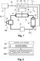
Figure 1 shows a block diagram illustrating schematically an HVAC system with a fluid circuit comprising a pump, a valve, and a thermal energy exchanger, and a control device for controlling the opening of the valve to regulate the amount of energy exchanged by the thermal energy exchanger. -
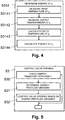
Figure 2 shows a flow diagram illustrating an exemplary sequence of steps for controlling the opening of the valve. -
Figure 3 shows a flow diagram illustrating an exemplary sequence of steps for determining the energy-per-flow gradient of the thermal energy exchanger. -
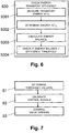
Figure 4 shows a flow diagram illustrating an exemplary sequence of steps for determining the energy exchanged by the thermal energy exchanger at a given point in time. -
Figure 5 shows a flow diagram illustrating an exemplary sequence of steps for controlling the opening of the valve including the checking of the efficiency of energy transport in the fluid circuit. -
Figure 6 shows a flow diagram illustrating an exemplary sequence of steps for checking the efficiency of the energy transport in the fluid circuit. -
Figure 7 shows a flow diagram illustrating an exemplary sequence of steps for determining threshold values and/or calibrating control signals used for controlling the opening of the valve. -
Figure 8 shows a flow diagram illustrating an exemplary sequence of steps for determining threshold values used for controlling the opening of the valve. -
Figure 9 shows a flow diagram illustrating an exemplary sequence of steps for calibrating control signals used for controlling an actuator of the valve. -
Figure 10 shows a flow diagram illustrating an exemplary sequence of steps for controlling the opening of the valve in a fluid circuit with a heat exchanger. -
Figure 11 shows a flow diagram illustrating an exemplary sequence of steps for controlling the opening of the valve in a fluid circuit with a chiller. -
Figure 12 shows a graph illustrating an example of the energy-per-flow curve with different points in time for determining the energy-per-flow gradient for different levels of flow and corresponding amounts of energy exchanged by the thermal energy exchanger. -
Figure 13 shows a graph illustrating an example of the energy-per-flow curve with different points in time for determining different energy-per-flow gradients in the process of calibrating control signals used to control an actuator of the valve. - In
Figure 1 ,reference numeral 100 refers to an HVAC system with afluid circuit 101 comprising apump 3, avalve 10, athermal energy exchanger 2, e.g. a heat exchanger for heating or cooling a room, and optionally a further thermal energy exchanger in the form of achiller 5, which are interconnected by way of pipes. Thevalve 10 is provided with anactuator 11, e.g. an electrical motor, for opening and closing thevalve 10 and thus controlling the flow through thefluid circuit 101, using different positions of thevalve 10. Further, the pump(s) 3 may themselves vary the flow through thefluid circuit 101. As illustrated schematically, theHVAC system 100 further comprises abuilding control system 4 connected to thevalve 10 oractuator 11, respectively. One skilled in the art will understand that the depiction of theHVAC system 100 is very simplified and that theHVAC system 100 may include a plurality offluid circuits 101, having in each case one ormore pumps 3, valves 19,thermal energy exchangers 2, andoptional chillers 5. - As illustrated schematically in
Figure 1 , thethermal energy exchanger 2 is provided with twotemperature sensors thermal energy exchanger 2, for measuring the input temperature Tin of the fluid entering thethermal energy exchanger 2, and at the exit of thethermal energy exchanger 2, for measuring the output temperature Tout of the fluid exiting thethermal energy exchanger 2. For example, the fluid is a liquid heat transportation medium such as water. - The
fluid circuit 101 further comprises aflow sensor 13 for measuring the flow ϕ, i.e. the rate of fluid flow, through thevalve 10 orfluid circuit 101, respectively. Depending on the embodiment, theflow sensor 13 is arranged in or at thevalve 10, or in or at apipe section 12 connected to thevalve 10. For example, theflow sensor 13 is an ultrasonic sensor or a heat transport sensor. - In
Figure 1 ,reference numeral 1 refers to a control device for controlling thevalve 10 or theactuator 11, respectively, to adjust the opening (or position) of thevalve 10. Accordingly, thecontrol device 1 regulates the flow ϕ, i.e. the rate of fluid flow, through thevalve 10 and, thus, through thethermal energy exchanger 2. Consequently, thecontrol device 1 regulates the amount of thermal energy exchanged by thethermal energy exchanger 2 with its environment. Depending on the embodiment, thecontrol device 1 is arranged at thevalve 10, e.g. as an integral part of thevalve 10 or attached to thevalve 10, or thecontrol device 1 is arranged at apipe section 12 connected to thevalve 10. - The
control device 1 comprises a microprocessor with program and data memory, or another programmable unit. Thecontrol device 1 comprises various functional modules including agradient generator 14, acontrol module 15, and acalibration module 16. Preferably, the functional modules are implemented as programmed software modules. The programmed software modules comprise computer code for controlling one or more processors or another programmable unit of thecontrol device 1, as will be explained later in more detail. The computer code is stored on a computer-readable medium which is connected to thecontrol device 1 in a fixed or removable way. One skilled in the art will understand, however, that in alternative embodiments, the functional modules can be implemented partly or fully by way of hardware components. - As is illustrated in
Figure 1 , theflow sensor 13 is connected to thecontrol device 1 for providing timely or current-time measurement values of the flow ϕ to thecontrol device 1. Furthermore, thecontrol device 1 is connected to theactuator 11 for supplying control signals Z to theactuator 11 for controlling theactuator 11 to open and/or close thevalve 10, i.e. to adjust the opening (or position) of thevalve 10. - Moreover, the
temperature sensors thermal energy exchanger 2 are connected to thecontrol device 1 for providing to thecontrol device 1 timely or current-time measurement values of the input temperature Tin and the output temperature Tout of the fluid entering or exiting thethermal energy exchanger 2, respectively. - Preferably, the
control device 1 is further connected to thebuilding control system 4 for receiving from thebuilding control system 4 control parameters, e.g. user settings for a desired room temperature, and/or measurement values, such as the load demand (from zero BTU to maximum BTU) or transport energy ET currently used by thepump 3 to transport the fluid through thefluid circuit 101, as measured byenergy measurement unit 31. Based on the transport energy ET used by a plurality ofpumps 3 and received at thebuilding control system 4 from a plurality of fluid circuits 101 (through transmission in push mode or retrieval in pull mode), thebuilding control system 4 is configured to optimize the overall efficiency of theHVAC system 100, e.g. by setting the flow ϕ through thevalve 10 of one or morefluid circuits 101 based on the total value of the transport energy ET used by all thepumps 3 of theHVAC system 100. In an alternative or additional embodiment, an energy sensor arranged at thepump 3 is connected directly to thecontrol device 1 for providing the current measurement value of the transport energy ET to thecontrol device 1. - In the following paragraphs, described with reference to
Figures 2-11 are possible sequences of steps performed by the functional modules of thecontrol device 1 for controlling the opening (or position) of thevalve 10 to regulate the flow ϕ through thethermal energy exchanger 2. - As illustrated in
Figure 2 , in step S3, thecontrol device 1 controls the opening of thevalve 10. Specifically, in step S31, thegradient generator 14 determines the energy-per-flow gradient
control module 15 controls the opening of thevalve 10 depending on the energy-per-flow gradient
- As illustrated in
Figures 3 and12 , for determining the energy-per-flow gradient
gradient generator 14 determines the flow ϕ n-1 through thevalve 10 at a defined time t n-1. Depending on the embodiment, thegradient generator 14 determines the flow ϕn-1 by sampling, polling or reading theflow sensor 13 at the defined time t n-1 or by reading a data store containing the flow ϕ n-1 measured by theflow sensor 13 at the defined time t n-1 . - In step S312, the
gradient generator 14 determines the amount of energy E n-1 exchanged by thethermal energy exchanger 2 at the defined time t n-1 . - In step S313, the
gradient generator 14 determines from theflow sensor 13 the flow ϕn through thevalve 10 at a defined subsequent time tn. - In step S314, the
gradient generator 14 determines the amount of energy En exchanged by thethermal energy exchanger 2 at the defined subsequent time tn. - In step S315, based on the flow ϕ n-1 , ϕn and exchanged energy E n-1 , En determined for the defined times t n-1 tn, the
gradient generator 14 calculates the energy-per-flow gradient
- Subsequently, the
gradient generator 14 proceeds in steps S313 and S314 by determining the flow ϕ n+1 and exchanged energy E n+1 for the defined time t n+1 , and calculates the energy-per-flow gradient
Figure 12 , the energy-per-flow gradient
- As illustrated in
Figure 4 , for determining the amount of energy En exchanged by thethermal energy exchanger 2 at the defined time tn, in steps S3141 and S3142, thegradient generator 14 determines the input and output temperatures Tin , Tout measured at the inlet or outlet, respectively, of thethermal energy exchanger 2 at the defined time tn. Depending on the embodiment, thegradient generator 14 determines the input and output temperatures Tin , Tout by sampling, polling or reading thetemperature sensors temperature sensors - In step S3143, the
gradient generator 14 calculates the temperature difference ΔT = Tin - Tout between the input temperature Tin and the output temperature Tout. - In step S3144, the
gradient generator 14 calculates the amount of energy En = ΔT · ϕn exchanged by thethermal energy exchanger 2 from the flow ϕn and the temperature difference ΔT determined for the defined time tn. - In the embodiment according to
Figure 5 , before the energy-per-flow gradient
control module 15 checks the energy transport efficiency in step S30 and, subsequently, controls the opening of the valve depending on the energy transport efficiency. If the energy transport efficiency is sufficient, processing continues in step S31; otherwise, further opening of thevalve 10 is stopped and/or the opening of thevalve 10 is reduced, e.g. by reducing the control signal Z by a defined decrement. - As is illustrated in
Figure 6 , for checking the energy transport efficiency, in step S301 thecontrol module 15 measures the transport energy ET used by thepump 3 to transport the fluid through thefluid circuit 101 to thethermal energy exchanger 2. Depending on the embodiment, thecontrol module 15 determines the transport energy ET by polling or reading theenergy measurement unit 31 at a defined time tn, or by reading a data store containing the transport energy ET measured by theenergy measurement unit 31 at a defined time tn. - In step S302, the
control module 15 or thegradient generator 14, respectively, determines the amount of energy En exchanged by thethermal energy exchanger 2 at the defined time tn. - In step S303, the
control module 15 calculates the energy balance EB = En - ET from the determined transport energy ET and amount of exchanged energy En. - In step S305, the
control module 15 checks the energy transport efficiency by comparing the calculated energy balance EB to an efficiency threshold KE . For example, the energy efficiency is considered positive, if the energy balance EB exceeds the efficiency threshold EB > KE , e.g. KE = 0. Depending on the embodiment, the efficiency threshold KE is a fixed value stored in thecontrol device 1 or entered from an external source. - In the embodiment according to
Figure 7 , step S3 for controlling the valve opening is preceded by optional steps S1 and/or S2 for determining one or more slope threshold values and/or calibrating the control signal Z values for controlling theactuator 11 to open and/or close thevalve 10. Preferably, for a continuous optimization of system accuracy, the calibration sequence, including steps S1 and/or S2, is not only performed initially, at start-up time, but is re-initiated automatically upon occurrence of defined events, specifically, upon changes of defined system variables such as changes in the input temperature Tin as sensed by thetemperature sensor 21; rapid and/or significant changes of various inputs from thebuilding control system 4 such as return air temperature, outside air temperature, temperature drop across the air side of theheat exchanger 2; or any signal that represents a change in the load conditions. - As illustrated in
Figure 8 , for determining the slope threshold value(s) for controlling the valve opening, in step S10, thecontrol module 15 opens the valve from an initial closed position. Specifically, in this initial phase, thevalve 10 is opened to a defined opening level and/or by a defined increment of the value of the control signal Z. - In step S11, during this initial phase, the
gradient generator 14 determines the energy-per-flow gradient 
Figure 12 ), as described above with reference toFigure 3 . - In step S12, the
control module 15 sets the slope threshold value(s) based on the energy-per-flow gradient 
flow gradient 
chiller 5, a lower slope threshold value KL and an upper slope threshold value KH are set in each case to a defined percentage C, D of the energy-per-flow gradient

Figure 12 , the slope threshold value K 0 defines a point PK where for a flow ϕK and amount of energy EK exchanged by thethermal energy exchanger 2, the energy-per-flow gradient 
- In an alternative less preferred embodiment, the slope thresholds K 0, KL , KH are defined (constant) values assigned specifically to the
thermal energy exchanger 2, e.g. type-specific constants entered and/or stored in a data store of thecontrol device 1 or thethermal energy exchanger 2. - As illustrated in
Figures 9 and13 , for calibrating the values of the control signal Z, in step S21, thecalibration module 16 sets the control signal Z to a defined maximum control signal value Zmax, e.g. 10V. Accordingly, in the calibration phase, theactuator 11 drives thevalve 10 to a maximum opening position, e.g. to a fully open position with maximum flow ϕmax corresponding to a maximum BTU (British Thermal Unit). - In step S22, the
gradient generator 14 determines the energy-per-flow gradient
Figure 3 for the current valve opening. - In step S23, the
calibration module 16 checks if the determined energy-per-flow gradient


- In step S24, the
calibration module 16 reduces the valve opening, e.g. by reducing the control signal Z by a defined decrement, e.g. by 0.1V, to a lower control signal level Zn+1, Zn and continues by determining the energy-per-flow gradient
valve 10 with reduced flow ϕ n+1, ϕ n. - In step S25, when the
valve 10 is set to an opening where the energy-per-flow gradient
calibration module 16 calibrates the control signal Z by assigning the maximum value for the control signal Zmax to the current opening level of thevalve 10. For example, if
valve 10 of 80% with flow ϕ n, the maximum value Zmax of e.g. 10V for the control signal Z is assigned to the opening level of 80%. When the control signal Z is subsequently set to its maximum level Zmax, e.g. as required by a load demand from thebuilding control system 4, thevalve 10 is set to an opening level with flow ϕ n that results in an energy-per-flow gradient
-
Figure 10 illustrates an exemplary sequence of steps S3H for controlling the valve opening for athermal energy converter 2 in the form of a heat exchanger. - In step S30H, the
control module 15 opens thevalve 10 from an initial closed position. Specifically, in this initial phase, thevalve 10 is opened to a defined opening level and/or by a defined increment of the value of the control signal Z. - In step S31H, the
gradient generator 14 determines the energy-per-flow gradient
Figure 3 for the current valve opening. - In step S32H, the
control module 15 checks whether the determined energy-per-flow gradient
- If the energy-per-flow gradient

valve 10. Otherwise, if the energy-per-flow gradient
valve 10 and/or by reducing the opening of thevalve 10, e.g. by reducing the control signal Z by a defined decrement. -
Figure 11 illustrates an exemplary sequence of steps S3C for controlling the valve opening for a thermal energy converter in the form of achiller 5. - In step S30C, the
control module 15 opens thevalve 10 from an initial closed position or reduces the opening from an initial open position. Specifically, in this initial phase, thevalve 10 is opened or its opening is reduced, respectively, to a defined opening level and/or by a defined increment (or decrement) of the value of the control signal Z. - In step S31C, the
gradient generator 14 determines the energy-per-flow gradient
Figure 3 for the current valve opening. - In step S32C, the
control module 15 checks whether the determined energy-per-flow gradient
- If the energy-per-flow gradient

valve 10 or by continuing to decrease the control signal Z to further close thevalve 10, respectively. Otherwise, if the energy-per-flow gradient
valve 10, respectively, as thechiller 5 no longer operates in the efficient range.
Claims (15)
- A method of controlling opening (S3) of a valve (10) in an HVAC system (100) to regulate the flow ϕ of a fluid through a thermal energy exchanger (2) of the HVAC system (100) and adjust the amount of energy E exchanged by the thermal energy exchanger (2), the method comprising:determining (S31) an energy-per-flow gradient
 controlling the opening (S32) of the valve (10) depending on the energy-per-flow gradient
- The method of claim 1, wherein determining (S31) the energy-per-flow gradient


- The method of one of claims 1 or 2, wherein determining (S314) the amount of energy exchanged by the thermal energy exchanger (2) comprises measuring the flow ϕ (S313) through the valve (10), determining (S3143) between an input temperature Tin of the fluid entering the thermal energy exchanger (2) and an output temperature T out of the fluid exiting the thermal energy exchanger (2) a temperature difference ΔT = Tin - Tout , and calculating (S3144), based on the flow ϕ through the valve (10) and the temperature difference ΔT, the amount of energy E = ΔT · ϕ exchanged by the thermal energy exchanger (2).
- The method of one of claims 1 to 3, further comprising measuring (S301) a transport energy ET used to transport the fluid through the HVAC system (100); determining (S302) the amount of energy E exchanged by the thermal energy exchanger (2); determining (S303), based on the transport energy ET and the amount of energy E exchanged by the thermal energy exchanger (2), an energy balance EB = E - ET ; comparing (S304) the energy balance EB to an efficiency threshold; and controlling the opening of the valve (10) depending on the comparing.
- The method of one of claims 1 to 4, wherein the opening of valve (10) is controlled (S3H) to regulate the flow ϕ of the fluid through a heat exchanger of the HVAC system (100); the energy-per-flow gradient


- The method of one of claims 1 to 5, wherein the valve (10) is controlled (S3C) to regulate the flow ϕ of the fluid through a chiller (5) of the HVAC system (100); the energy-per-flow gradient


- The method of one of claims 5 or 6, further comprising determining (S1) the slope threshold by determining (S11) the energy-per-flow gradient


- The method of one of claims 1 to 7, further comprising calibrating (S2) control signal (Z) levels which are used to control an actuator (11) of the valve (10) for opening the valve (10), by setting (S21) the control signal (Z) to a defined maximum value for placing the valve (10) to a maximum opening position, reducing (S24) the value of the control signal (Z) to reduce the opening of the valve (10) while determining the energy-per-flow gradient


- A control device (1) for controlling opening of a valve (10) in an HVAC system (100) to regulate the flow ϕ of a fluid through a thermal energy exchanger (2) of the HVAC system (100) and adjust the amount of energy E exchanged by the thermal energy exchanger (2), the control device (1) is characterised in that:a gradient generator (14) configured to determine an energyper-flow gradient
 a control module (15) configured to control the opening of the valve (10) depending on the energy-per-flow gradient
- The control device (1) of claim 9, wherein the gradient generator (14) is configured to calculate the energy-per-flow gradient

- The control device (1) of one of claims 9 or 10, wherein the gradient generator (14) is configured to calculate the amount of energy E = ΔT · ϕ exchanged by the thermal energy exchanger (2) from a measurement of the flow ϕ through the valve (10), and a temperature difference ΔT = Tin - Tout determined between an input temperature Tin of the fluid entering the thermal energy exchanger (2) and an output temperature Tout of the fluid exiting the thermal energy exchanger (2).
- The control device (1) of one of claims 9 to 11, wherein, for regulating the flow ϕ of the fluid through a heat exchanger of the HVAC system (100), the control module (15) is configured to control the opening of the valve (10) by having the gradient generator (14) determine the energy-per-flow gradient


- The control device (1) of one of claims 9 to 12, wherein, for regulating the flow ϕ of the fluid through a chiller (5) of the HVAC system (100), the control module (15) is configured to control the opening of the valve (10) by having the gradient generator (14) determine the energy-per-flow gradient


- The control device (1) of one of claims 12 or 13, wherein the control module (15) is further configured to determine the slope threshold by having the gradient generator (14) determine the energy-per-flow gradient


- The control device (1) of one of claims 9 to 14, further comprising a calibration module (16) configured to calibrate control signal levels (Z) which are used to control an actuator (11) of the valve (10) for opening the valve (10), by setting the control signal (Z) to a defined maximum value for placing the valve (10) to a maximum opening position, reducing the value of the control signal (Z) to reduce the opening of the valve (10) while having the gradient generator (14) determine the energy-per-flow gradient


Applications Claiming Priority (2)
| Application Number | Priority Date | Filing Date | Title |
|---|---|---|---|
| CH19262010 | 2010-11-17 | ||
| PCT/CH2011/000246 WO2012065275A1 (en) | 2010-11-17 | 2011-10-18 | Device and method for controlling opening of a valve in an hvac system |
Publications (2)
| Publication Number | Publication Date |
|---|---|
| EP2641027A1 EP2641027A1 (en) | 2013-09-25 |
| EP2641027B1 true EP2641027B1 (en) | 2017-11-22 |
Family
ID=43710375
Family Applications (1)
| Application Number | Title | Priority Date | Filing Date |
|---|---|---|---|
| EP11773661.1A Active EP2641027B1 (en) | 2010-11-17 | 2011-10-18 | Device and method for controlling opening of a valve in an hvac system |
Country Status (7)
| Country | Link |
|---|---|
| US (1) | US9631831B2 (en) |
| EP (1) | EP2641027B1 (en) |
| CN (1) | CN103228996B (en) |
| CA (1) | CA2811775A1 (en) |
| DK (1) | DK2641027T3 (en) |
| RU (1) | RU2573378C2 (en) |
| WO (1) | WO2012065275A1 (en) |
Families Citing this family (22)
| Publication number | Priority date | Publication date | Assignee | Title |
|---|---|---|---|---|
| EP3506521A1 (en) * | 2010-10-01 | 2019-07-03 | CommScope Technologies LLC | Distributed antenna system for mimo signals |
| WO2012160598A1 (en) * | 2011-05-23 | 2012-11-29 | 三菱電機株式会社 | Air conditioner |
| CH706146A2 (en) * | 2012-02-29 | 2013-08-30 | Oblamatik Ag | Method and system for tempering components. |
| US9534795B2 (en) | 2012-10-05 | 2017-01-03 | Schneider Electric Buildings, Llc | Advanced valve actuator with remote location flow reset |
| US10295080B2 (en) | 2012-12-11 | 2019-05-21 | Schneider Electric Buildings, Llc | Fast attachment open end direct mount damper and valve actuator |
| SI2971901T1 (en) * | 2013-03-15 | 2019-01-31 | Schneider Electric Buildings, Llc | Advanced valve actuator with integral energy metering |
| EP2971883B8 (en) | 2013-03-15 | 2020-07-15 | Schneider Electric Buildings, LLC | Advanced valve actuator with true flow feedback |
| CN105378575B (en) * | 2013-05-16 | 2018-09-07 | 贝利莫控股公司 | Device and method for the aperture for controlling the valve in HVAC system |
| EP3344925B1 (en) * | 2015-09-01 | 2021-05-26 | Belimo Holding AG | Method and system for operating a thermal energy exchanger |
| ITUB20153497A1 (en) | 2015-09-09 | 2017-03-09 | Fimcim Spa | AIR-CONDITIONING AND / OR HEATING SYSTEM AND PROCESS OF CONTROL OF THE SAME PLANT |
| ITUB20153506A1 (en) | 2015-09-09 | 2017-03-09 | Fimcim Spa | AIR-CONDITIONING AND / OR HEATING SYSTEM AND PROCESS OF CONTROL OF THE SAME PLANT |
| WO2019040884A1 (en) | 2017-08-25 | 2019-02-28 | Johnson Controls Technology Company | Temperature control valve |
| CN112424538A (en) * | 2018-06-12 | 2021-02-26 | 贝利莫控股公司 | Method and system for controlling energy transfer of a thermal energy exchanger |
| US10739017B2 (en) | 2018-08-20 | 2020-08-11 | Computime Ltd. | Determination of hydronic valve opening point |
| EP3623896B1 (en) * | 2018-09-12 | 2021-04-28 | Fimcim S.P.A. | Method and device for controlling the flow of a fluid in an air-conditioning and/or heating system |
| US11092354B2 (en) | 2019-06-20 | 2021-08-17 | Johnson Controls Tyco IP Holdings LLP | Systems and methods for flow control in an HVAC system |
| US11149976B2 (en) * | 2019-06-20 | 2021-10-19 | Johnson Controls Tyco IP Holdings LLP | Systems and methods for flow control in an HVAC system |
| US11391480B2 (en) | 2019-12-04 | 2022-07-19 | Johnson Controls Tyco IP Holdings LLP | Systems and methods for freeze protection of a coil in an HVAC system |
| US11624524B2 (en) | 2019-12-30 | 2023-04-11 | Johnson Controls Tyco IP Holdings LLP | Systems and methods for expedited flow sensor calibration |
| US11519631B2 (en) | 2020-01-10 | 2022-12-06 | Johnson Controls Tyco IP Holdings LLP | HVAC control system with adaptive flow limit heat exchanger control |
| WO2023030943A1 (en) * | 2021-08-30 | 2023-03-09 | Belimo Holding Ag | A method of operating an hvac system |
| WO2023180095A1 (en) | 2022-03-21 | 2023-09-28 | Belimo Holding Ag | Method and devices for controlling a flow control system |
Family Cites Families (16)
| Publication number | Priority date | Publication date | Assignee | Title |
|---|---|---|---|---|
| US4215408A (en) * | 1977-12-12 | 1980-07-29 | United Technologies Corporation | Temperature control of unoccupied living spaces |
| DE2811153A1 (en) * | 1978-03-15 | 1979-09-20 | Wolfgang Behm | Automatic room heating control system - uses supply and return flow temps. under stationary conditions to establish flow temp. and control circuit |
| US4279381A (en) * | 1979-09-28 | 1981-07-21 | Yang Yueh | Method for uniformly heating a multi-level building |
| CH641889A5 (en) * | 1980-02-04 | 1984-03-15 | Landis & Gyr Ag | HEATING SYSTEM. |
| SE446905B (en) * | 1985-04-29 | 1986-10-13 | Tour & Andersson Ab | SETS AND MEASURES TO REGULATE THE FLOOD RESP TEMPERATURE Separately AT FLOOR HEATING INSTALLATIONS |
| JPH06103130B2 (en) * | 1990-03-30 | 1994-12-14 | 株式会社東芝 | Air conditioner |
| FI92868C (en) | 1993-07-07 | 1996-02-06 | Abb Installaatiot Oy | Method and apparatus for controlling the heat transfer in an air-exchange or air-conditioning system |
| US6352106B1 (en) | 1999-05-07 | 2002-03-05 | Thomas B. Hartman | High-efficiency pumping and distribution system incorporating a self-balancing, modulating control valve |
| US7426910B2 (en) * | 2006-10-30 | 2008-09-23 | Ford Global Technologies, Llc | Engine system having improved efficiency |
| JP2009031866A (en) * | 2007-07-24 | 2009-02-12 | Yamatake Corp | Flow control valve and flow control method |
| US7848853B2 (en) * | 2008-05-13 | 2010-12-07 | Solarlogic, Llc | System and method for controlling hydronic systems having multiple sources and multiple loads |
| DE102009004319A1 (en) | 2009-01-10 | 2010-07-22 | Henry Klein | Method for performing hydraulic balance of heat exchanger of circulatory composite system in building, involves detecting return temperature at heat exchanger and controlling volumetric flow rate by heat exchanger as function of temperature |
| WO2011099065A1 (en) * | 2010-02-10 | 2011-08-18 | 三菱電機株式会社 | Air conditioner |
| US9995493B2 (en) * | 2010-04-14 | 2018-06-12 | Robert J. Mowris | Efficient fan controller |
| JP5370560B2 (en) * | 2011-09-30 | 2013-12-18 | ダイキン工業株式会社 | Refrigerant cycle system |
| CN105378575B (en) * | 2013-05-16 | 2018-09-07 | 贝利莫控股公司 | Device and method for the aperture for controlling the valve in HVAC system |
-
2011
- 2011-10-18 WO PCT/CH2011/000246 patent/WO2012065275A1/en active Application Filing
- 2011-10-18 EP EP11773661.1A patent/EP2641027B1/en active Active
- 2011-10-18 US US13/885,925 patent/US9631831B2/en active Active
- 2011-10-18 RU RU2013127193/12A patent/RU2573378C2/en not_active IP Right Cessation
- 2011-10-18 CA CA2811775A patent/CA2811775A1/en not_active Abandoned
- 2011-10-18 DK DK11773661.1T patent/DK2641027T3/en active
- 2011-10-18 CN CN201180055591.7A patent/CN103228996B/en active Active
Also Published As
| Publication number | Publication date |
|---|---|
| CN103228996A (en) | 2013-07-31 |
| CN103228996B (en) | 2015-12-16 |
| CA2811775A1 (en) | 2012-05-24 |
| DK2641027T3 (en) | 2018-03-05 |
| EP2641027A1 (en) | 2013-09-25 |
| US20140083673A1 (en) | 2014-03-27 |
| WO2012065275A1 (en) | 2012-05-24 |
| RU2013127193A (en) | 2014-12-27 |
| US9631831B2 (en) | 2017-04-25 |
| RU2573378C2 (en) | 2016-01-20 |
Similar Documents
| Publication | Publication Date | Title |
|---|---|---|
| EP2641027B1 (en) | Device and method for controlling opening of a valve in an hvac system | |
| EP2997430B1 (en) | Device and method for controlling the opening of a valve in an hvac system | |
| US10635120B2 (en) | Method for operating and/or monitoring an HVAC system | |
| US6522954B1 (en) | Smart control strategy for regulating a temperature controller | |
| EP3483690B1 (en) | A method for controlling a fluid flow through a valve | |
| EP3306216B1 (en) | Control device for heat-pump-using system, and heat-pump-using system provided with same | |
| US10801737B2 (en) | Method for adapting a heating curve | |
| US9702569B2 (en) | Method for the temperature control of components | |
| EP1496316B1 (en) | Air conditioner, and method of controlling air conditioner | |
| EP3751381B1 (en) | Flow control module and method for controlling the flow in a hydronic system | |
| RU2557150C2 (en) | Equalising valve | |
| US9671120B2 (en) | Thermal source instrument controlling device and air-conditioning system | |
| EP3073205B1 (en) | Method for operating a hydronic heating and/or cooling system, control valve and hydronic heating and/or cooling system | |
| US11609019B2 (en) | Device and method for controlling an orifice of a valve in an HVAC system | |
| US20230127979A1 (en) | Automated Swimming Pool Heat Pump Flow Rate Controller | |
| EP3525060B1 (en) | Flow control module and method for controlling the flow in a hydronic system | |
| US20200340701A1 (en) | System and method for building climate control | |
| CN116989443A (en) | Self-learning feedback calibration method and device for regional energy heating and cooling system |
Legal Events
| Date | Code | Title | Description |
|---|---|---|---|
| PUAI | Public reference made under article 153(3) epc to a published international application that has entered the european phase |
Free format text: ORIGINAL CODE: 0009012 |
|
| 17P | Request for examination filed |
Effective date: 20130320 |
|
| AK | Designated contracting states |
Kind code of ref document: A1 Designated state(s): AL AT BE BG CH CY CZ DE DK EE ES FI FR GB GR HR HU IE IS IT LI LT LU LV MC MK MT NL NO PL PT RO RS SE SI SK SM TR |
|
| DAX | Request for extension of the european patent (deleted) | ||
| GRAP | Despatch of communication of intention to grant a patent |
Free format text: ORIGINAL CODE: EPIDOSNIGR1 |
|
| STAA | Information on the status of an ep patent application or granted ep patent |
Free format text: STATUS: GRANT OF PATENT IS INTENDED |
|
| INTG | Intention to grant announced |
Effective date: 20170407 |
|
| GRAS | Grant fee paid |
Free format text: ORIGINAL CODE: EPIDOSNIGR3 |
|
| GRAA | (expected) grant |
Free format text: ORIGINAL CODE: 0009210 |
|
| STAA | Information on the status of an ep patent application or granted ep patent |
Free format text: STATUS: THE PATENT HAS BEEN GRANTED |
|
| AK | Designated contracting states |
Kind code of ref document: B1 Designated state(s): AL AT BE BG CH CY CZ DE DK EE ES FI FR GB GR HR HU IE IS IT LI LT LU LV MC MK MT NL NO PL PT RO RS SE SI SK SM TR |
|
| REG | Reference to a national code |
Ref country code: GB Ref legal event code: FG4D |
|
| REG | Reference to a national code |
Ref country code: CH Ref legal event code: EP Ref country code: CH Ref legal event code: NV Representative=s name: RENTSCH PARTNER AG, CH |
|
| REG | Reference to a national code |
Ref country code: IE Ref legal event code: FG4D |
|
| REG | Reference to a national code |
Ref country code: AT Ref legal event code: REF Ref document number: 948777 Country of ref document: AT Kind code of ref document: T Effective date: 20171215 |
|
| REG | Reference to a national code |
Ref country code: DE Ref legal event code: R096 Ref document number: 602011043598 Country of ref document: DE |
|
| REG | Reference to a national code |
Ref country code: DK Ref legal event code: T3 Effective date: 20180226 |
|
| REG | Reference to a national code |
Ref country code: NL Ref legal event code: MP Effective date: 20171122 |
|
| REG | Reference to a national code |
Ref country code: LT Ref legal event code: MG4D |
|
| REG | Reference to a national code |
Ref country code: AT Ref legal event code: MK05 Ref document number: 948777 Country of ref document: AT Kind code of ref document: T Effective date: 20171122 |
|
| PG25 | Lapsed in a contracting state [announced via postgrant information from national office to epo] |
Ref country code: NL Free format text: LAPSE BECAUSE OF FAILURE TO SUBMIT A TRANSLATION OF THE DESCRIPTION OR TO PAY THE FEE WITHIN THE PRESCRIBED TIME-LIMIT Effective date: 20171122 Ref country code: NO Free format text: LAPSE BECAUSE OF FAILURE TO SUBMIT A TRANSLATION OF THE DESCRIPTION OR TO PAY THE FEE WITHIN THE PRESCRIBED TIME-LIMIT Effective date: 20180222 Ref country code: ES Free format text: LAPSE BECAUSE OF FAILURE TO SUBMIT A TRANSLATION OF THE DESCRIPTION OR TO PAY THE FEE WITHIN THE PRESCRIBED TIME-LIMIT Effective date: 20171122 Ref country code: SE Free format text: LAPSE BECAUSE OF FAILURE TO SUBMIT A TRANSLATION OF THE DESCRIPTION OR TO PAY THE FEE WITHIN THE PRESCRIBED TIME-LIMIT Effective date: 20171122 Ref country code: LT Free format text: LAPSE BECAUSE OF FAILURE TO SUBMIT A TRANSLATION OF THE DESCRIPTION OR TO PAY THE FEE WITHIN THE PRESCRIBED TIME-LIMIT Effective date: 20171122 Ref country code: FI Free format text: LAPSE BECAUSE OF FAILURE TO SUBMIT A TRANSLATION OF THE DESCRIPTION OR TO PAY THE FEE WITHIN THE PRESCRIBED TIME-LIMIT Effective date: 20171122 |
|
| PG25 | Lapsed in a contracting state [announced via postgrant information from national office to epo] |
Ref country code: RS Free format text: LAPSE BECAUSE OF FAILURE TO SUBMIT A TRANSLATION OF THE DESCRIPTION OR TO PAY THE FEE WITHIN THE PRESCRIBED TIME-LIMIT Effective date: 20171122 Ref country code: BG Free format text: LAPSE BECAUSE OF FAILURE TO SUBMIT A TRANSLATION OF THE DESCRIPTION OR TO PAY THE FEE WITHIN THE PRESCRIBED TIME-LIMIT Effective date: 20180222 Ref country code: AT Free format text: LAPSE BECAUSE OF FAILURE TO SUBMIT A TRANSLATION OF THE DESCRIPTION OR TO PAY THE FEE WITHIN THE PRESCRIBED TIME-LIMIT Effective date: 20171122 Ref country code: GR Free format text: LAPSE BECAUSE OF FAILURE TO SUBMIT A TRANSLATION OF THE DESCRIPTION OR TO PAY THE FEE WITHIN THE PRESCRIBED TIME-LIMIT Effective date: 20180223 Ref country code: HR Free format text: LAPSE BECAUSE OF FAILURE TO SUBMIT A TRANSLATION OF THE DESCRIPTION OR TO PAY THE FEE WITHIN THE PRESCRIBED TIME-LIMIT Effective date: 20171122 Ref country code: LV Free format text: LAPSE BECAUSE OF FAILURE TO SUBMIT A TRANSLATION OF THE DESCRIPTION OR TO PAY THE FEE WITHIN THE PRESCRIBED TIME-LIMIT Effective date: 20171122 |
|
| PG25 | Lapsed in a contracting state [announced via postgrant information from national office to epo] |
Ref country code: CZ Free format text: LAPSE BECAUSE OF FAILURE TO SUBMIT A TRANSLATION OF THE DESCRIPTION OR TO PAY THE FEE WITHIN THE PRESCRIBED TIME-LIMIT Effective date: 20171122 Ref country code: SK Free format text: LAPSE BECAUSE OF FAILURE TO SUBMIT A TRANSLATION OF THE DESCRIPTION OR TO PAY THE FEE WITHIN THE PRESCRIBED TIME-LIMIT Effective date: 20171122 Ref country code: CY Free format text: LAPSE BECAUSE OF FAILURE TO SUBMIT A TRANSLATION OF THE DESCRIPTION OR TO PAY THE FEE WITHIN THE PRESCRIBED TIME-LIMIT Effective date: 20171122 Ref country code: EE Free format text: LAPSE BECAUSE OF FAILURE TO SUBMIT A TRANSLATION OF THE DESCRIPTION OR TO PAY THE FEE WITHIN THE PRESCRIBED TIME-LIMIT Effective date: 20171122 |
|
| REG | Reference to a national code |
Ref country code: DE Ref legal event code: R097 Ref document number: 602011043598 Country of ref document: DE |
|
| PG25 | Lapsed in a contracting state [announced via postgrant information from national office to epo] |
Ref country code: RO Free format text: LAPSE BECAUSE OF FAILURE TO SUBMIT A TRANSLATION OF THE DESCRIPTION OR TO PAY THE FEE WITHIN THE PRESCRIBED TIME-LIMIT Effective date: 20171122 Ref country code: PL Free format text: LAPSE BECAUSE OF FAILURE TO SUBMIT A TRANSLATION OF THE DESCRIPTION OR TO PAY THE FEE WITHIN THE PRESCRIBED TIME-LIMIT Effective date: 20171122 Ref country code: IT Free format text: LAPSE BECAUSE OF FAILURE TO SUBMIT A TRANSLATION OF THE DESCRIPTION OR TO PAY THE FEE WITHIN THE PRESCRIBED TIME-LIMIT Effective date: 20171122 Ref country code: SM Free format text: LAPSE BECAUSE OF FAILURE TO SUBMIT A TRANSLATION OF THE DESCRIPTION OR TO PAY THE FEE WITHIN THE PRESCRIBED TIME-LIMIT Effective date: 20171122 |
|
| PLBE | No opposition filed within time limit |
Free format text: ORIGINAL CODE: 0009261 |
|
| STAA | Information on the status of an ep patent application or granted ep patent |
Free format text: STATUS: NO OPPOSITION FILED WITHIN TIME LIMIT |
|
| 26N | No opposition filed |
Effective date: 20180823 |
|
| PG25 | Lapsed in a contracting state [announced via postgrant information from national office to epo] |
Ref country code: SI Free format text: LAPSE BECAUSE OF FAILURE TO SUBMIT A TRANSLATION OF THE DESCRIPTION OR TO PAY THE FEE WITHIN THE PRESCRIBED TIME-LIMIT Effective date: 20171122 |
|
| GBPC | Gb: european patent ceased through non-payment of renewal fee |
Effective date: 20181018 |
|
| REG | Reference to a national code |
Ref country code: BE Ref legal event code: MM Effective date: 20181031 |
|
| PG25 | Lapsed in a contracting state [announced via postgrant information from national office to epo] |
Ref country code: MC Free format text: LAPSE BECAUSE OF FAILURE TO SUBMIT A TRANSLATION OF THE DESCRIPTION OR TO PAY THE FEE WITHIN THE PRESCRIBED TIME-LIMIT Effective date: 20171122 Ref country code: LU Free format text: LAPSE BECAUSE OF NON-PAYMENT OF DUE FEES Effective date: 20181018 |
|
| REG | Reference to a national code |
Ref country code: IE Ref legal event code: MM4A |
|
| PG25 | Lapsed in a contracting state [announced via postgrant information from national office to epo] |
Ref country code: FR Free format text: LAPSE BECAUSE OF NON-PAYMENT OF DUE FEES Effective date: 20181031 Ref country code: BE Free format text: LAPSE BECAUSE OF NON-PAYMENT OF DUE FEES Effective date: 20181031 |
|
| PG25 | Lapsed in a contracting state [announced via postgrant information from national office to epo] |
Ref country code: IE Free format text: LAPSE BECAUSE OF NON-PAYMENT OF DUE FEES Effective date: 20181018 Ref country code: GB Free format text: LAPSE BECAUSE OF NON-PAYMENT OF DUE FEES Effective date: 20181018 |
|
| PG25 | Lapsed in a contracting state [announced via postgrant information from national office to epo] |
Ref country code: MT Free format text: LAPSE BECAUSE OF NON-PAYMENT OF DUE FEES Effective date: 20181018 |
|
| PGFP | Annual fee paid to national office [announced via postgrant information from national office to epo] |
Ref country code: DK Payment date: 20191023 Year of fee payment: 9 |
|
| PG25 | Lapsed in a contracting state [announced via postgrant information from national office to epo] |
Ref country code: TR Free format text: LAPSE BECAUSE OF FAILURE TO SUBMIT A TRANSLATION OF THE DESCRIPTION OR TO PAY THE FEE WITHIN THE PRESCRIBED TIME-LIMIT Effective date: 20171122 |
|
| PG25 | Lapsed in a contracting state [announced via postgrant information from national office to epo] |
Ref country code: PT Free format text: LAPSE BECAUSE OF FAILURE TO SUBMIT A TRANSLATION OF THE DESCRIPTION OR TO PAY THE FEE WITHIN THE PRESCRIBED TIME-LIMIT Effective date: 20171122 |
|
| PG25 | Lapsed in a contracting state [announced via postgrant information from national office to epo] |
Ref country code: MK Free format text: LAPSE BECAUSE OF NON-PAYMENT OF DUE FEES Effective date: 20171122 Ref country code: HU Free format text: LAPSE BECAUSE OF FAILURE TO SUBMIT A TRANSLATION OF THE DESCRIPTION OR TO PAY THE FEE WITHIN THE PRESCRIBED TIME-LIMIT; INVALID AB INITIO Effective date: 20111018 |
|
| PG25 | Lapsed in a contracting state [announced via postgrant information from national office to epo] |
Ref country code: AL Free format text: LAPSE BECAUSE OF FAILURE TO SUBMIT A TRANSLATION OF THE DESCRIPTION OR TO PAY THE FEE WITHIN THE PRESCRIBED TIME-LIMIT Effective date: 20171122 Ref country code: IS Free format text: LAPSE BECAUSE OF FAILURE TO SUBMIT A TRANSLATION OF THE DESCRIPTION OR TO PAY THE FEE WITHIN THE PRESCRIBED TIME-LIMIT Effective date: 20180322 |
|
| REG | Reference to a national code |
Ref country code: DK Ref legal event code: EBP Effective date: 20201031 |
|
| PG25 | Lapsed in a contracting state [announced via postgrant information from national office to epo] |
Ref country code: DK Free format text: LAPSE BECAUSE OF NON-PAYMENT OF DUE FEES Effective date: 20201031 |
|
| P01 | Opt-out of the competence of the unified patent court (upc) registered |
Effective date: 20230513 |
|
| PGFP | Annual fee paid to national office [announced via postgrant information from national office to epo] |
Ref country code: DE Payment date: 20231018 Year of fee payment: 13 Ref country code: CH Payment date: 20231102 Year of fee payment: 13 |