EP2639580B1 - Monitoring the function of an electrolytic gas sensor with three electrodes and a hazard warning device and gas measuring device - Google Patents
Monitoring the function of an electrolytic gas sensor with three electrodes and a hazard warning device and gas measuring device Download PDFInfo
- Publication number
- EP2639580B1 EP2639580B1 EP13172931.1A EP13172931A EP2639580B1 EP 2639580 B1 EP2639580 B1 EP 2639580B1 EP 13172931 A EP13172931 A EP 13172931A EP 2639580 B1 EP2639580 B1 EP 2639580B1
- Authority
- EP
- European Patent Office
- Prior art keywords
- gas
- voltage
- output
- case
- impermissible
- Prior art date
- Legal status (The legal status is an assumption and is not a legal conclusion. Google has not performed a legal analysis and makes no representation as to the accuracy of the status listed.)
- Active
Links
- 238000012544 monitoring process Methods 0.000 title claims description 26
- 238000012545 processing Methods 0.000 claims description 27
- 238000000034 method Methods 0.000 claims description 20
- 238000005259 measurement Methods 0.000 claims description 12
- 230000007257 malfunction Effects 0.000 claims description 9
- 238000004891 communication Methods 0.000 claims description 7
- 230000001105 regulatory effect Effects 0.000 claims description 4
- 239000000779 smoke Substances 0.000 claims description 4
- 230000036962 time dependent Effects 0.000 claims description 4
- 238000001914 filtration Methods 0.000 claims description 3
- 238000011144 upstream manufacturing Methods 0.000 claims description 2
- 239000007789 gas Substances 0.000 description 151
- 238000001514 detection method Methods 0.000 description 25
- 230000006870 function Effects 0.000 description 13
- UGFAIRIUMAVXCW-UHFFFAOYSA-N Carbon monoxide Chemical compound [O+]#[C-] UGFAIRIUMAVXCW-UHFFFAOYSA-N 0.000 description 12
- 229910002091 carbon monoxide Inorganic materials 0.000 description 12
- 230000003287 optical effect Effects 0.000 description 12
- 230000008859 change Effects 0.000 description 5
- 238000006243 chemical reaction Methods 0.000 description 5
- 238000004590 computer program Methods 0.000 description 4
- VNWKTOKETHGBQD-UHFFFAOYSA-N methane Chemical compound C VNWKTOKETHGBQD-UHFFFAOYSA-N 0.000 description 4
- 239000003990 capacitor Substances 0.000 description 3
- 230000001419 dependent effect Effects 0.000 description 3
- 238000012360 testing method Methods 0.000 description 3
- QGZKDVFQNNGYKY-UHFFFAOYSA-N Ammonia Chemical compound N QGZKDVFQNNGYKY-UHFFFAOYSA-N 0.000 description 2
- CURLTUGMZLYLDI-UHFFFAOYSA-N Carbon dioxide Chemical compound O=C=O CURLTUGMZLYLDI-UHFFFAOYSA-N 0.000 description 2
- LFQSCWFLJHTTHZ-UHFFFAOYSA-N Ethanol Chemical compound CCO LFQSCWFLJHTTHZ-UHFFFAOYSA-N 0.000 description 2
- 230000001276 controlling effect Effects 0.000 description 2
- 239000001257 hydrogen Substances 0.000 description 2
- 229910052739 hydrogen Inorganic materials 0.000 description 2
- 230000002093 peripheral effect Effects 0.000 description 2
- 238000011084 recovery Methods 0.000 description 2
- 230000004044 response Effects 0.000 description 2
- 238000002604 ultrasonography Methods 0.000 description 2
- MGWGWNFMUOTEHG-UHFFFAOYSA-N 4-(3,5-dimethylphenyl)-1,3-thiazol-2-amine Chemical compound CC1=CC(C)=CC(C=2N=C(N)SC=2)=C1 MGWGWNFMUOTEHG-UHFFFAOYSA-N 0.000 description 1
- RWSOTUBLDIXVET-UHFFFAOYSA-N Dihydrogen sulfide Chemical compound S RWSOTUBLDIXVET-UHFFFAOYSA-N 0.000 description 1
- UFHFLCQGNIYNRP-UHFFFAOYSA-N Hydrogen Chemical compound [H][H] UFHFLCQGNIYNRP-UHFFFAOYSA-N 0.000 description 1
- 230000032683 aging Effects 0.000 description 1
- 229910021529 ammonia Inorganic materials 0.000 description 1
- 230000003321 amplification Effects 0.000 description 1
- QVGXLLKOCUKJST-UHFFFAOYSA-N atomic oxygen Chemical compound [O] QVGXLLKOCUKJST-UHFFFAOYSA-N 0.000 description 1
- 230000006399 behavior Effects 0.000 description 1
- 229910002092 carbon dioxide Inorganic materials 0.000 description 1
- 239000001569 carbon dioxide Substances 0.000 description 1
- 125000004122 cyclic group Chemical group 0.000 description 1
- 238000010586 diagram Methods 0.000 description 1
- 238000005516 engineering process Methods 0.000 description 1
- 238000011156 evaluation Methods 0.000 description 1
- 230000005284 excitation Effects 0.000 description 1
- 238000004868 gas analysis Methods 0.000 description 1
- 238000009499 grossing Methods 0.000 description 1
- 150000002431 hydrogen Chemical class 0.000 description 1
- 229910000037 hydrogen sulfide Inorganic materials 0.000 description 1
- 238000007689 inspection Methods 0.000 description 1
- 238000007620 mathematical function Methods 0.000 description 1
- JCXJVPUVTGWSNB-UHFFFAOYSA-N nitrogen dioxide Inorganic materials O=[N]=O JCXJVPUVTGWSNB-UHFFFAOYSA-N 0.000 description 1
- 238000003199 nucleic acid amplification method Methods 0.000 description 1
- 239000001301 oxygen Substances 0.000 description 1
- 229910052760 oxygen Inorganic materials 0.000 description 1
- 239000002245 particle Substances 0.000 description 1
- 238000004886 process control Methods 0.000 description 1
- 230000000284 resting effect Effects 0.000 description 1
- 230000000630 rising effect Effects 0.000 description 1
- 238000005070 sampling Methods 0.000 description 1
- 230000000638 stimulation Effects 0.000 description 1
- 230000035882 stress Effects 0.000 description 1
- 230000002123 temporal effect Effects 0.000 description 1
Images


Classifications
-
- G—PHYSICS
- G01—MEASURING; TESTING
- G01N—INVESTIGATING OR ANALYSING MATERIALS BY DETERMINING THEIR CHEMICAL OR PHYSICAL PROPERTIES
- G01N27/00—Investigating or analysing materials by the use of electric, electrochemical, or magnetic means
- G01N27/26—Investigating or analysing materials by the use of electric, electrochemical, or magnetic means by investigating electrochemical variables; by using electrolysis or electrophoresis
- G01N27/416—Systems
- G01N27/4163—Systems checking the operation of, or calibrating, the measuring apparatus
-
- G—PHYSICS
- G08—SIGNALLING
- G08B—SIGNALLING OR CALLING SYSTEMS; ORDER TELEGRAPHS; ALARM SYSTEMS
- G08B21/00—Alarms responsive to a single specified undesired or abnormal condition and not otherwise provided for
- G08B21/02—Alarms for ensuring the safety of persons
- G08B21/12—Alarms for ensuring the safety of persons responsive to undesired emission of substances, e.g. pollution alarms
- G08B21/14—Toxic gas alarms
Definitions
- the present invention relates to a method and a device for monitoring the function of an electrolytic, sensitive to a specific gas gas sensor with three electrodes, in particular with a working, reference and counter electrode, electrical faults such as short circuit, short to ground and interruptions of the individual electrodes or combinations thereof ,
- a voltage applied between the reference and working electrode differential voltage Based on this, the potential of the counter electrode is then regulated in such a way that the differential voltage becomes as small as possible. In this case, an approximately proportional to the gas concentration of the gas to be detected in the counter electrode flowing into a measuring current turns.
- a monitoring method for electrochemical sensors is known in which a small amplitude alternating voltage is applied to the sensor electrode. Subsequently, the impedance between the individual electrodes is measured in order to judge the condition of the sensor.
- the invention further relates to a hazard detector which has at least one electrolytic gas sensor sensitive to a specific gas and such a device for monitoring function.
- the hazard detector is preferably a gas detector, in particular a CO gas detector or carbon monoxide gas detector.
- the hazard detector has a first output unit for outputting a warning or alarm message when a determined respective gas concentration exceeds a predetermined threshold value or a time value dependent on the respective gas concentration threshold value. It has a second output unit for outputting an error message in the event of a determined malfunction of the respective gas sensor.
- Such danger detectors which are typically designed as point detectors, are used to detect an undesired occurrence of a dangerous situation, such as leakage and / or the emergence of a dangerous gas such as carbon monoxide, at an early stage. They are typically mounted in a hazard-monitored area, such as at appropriate locations within a building.
- the hazard detector can also have other detection units for hazard reporting, such as an operating according to the scattered light method optical detection unit for the detection of smoke particles or a temperature detection unit for the detection of heat in the event of a fire.
- Such a hazard detector is also referred to as a multi-criteria hazard detector.
- the respective detection signals are used to reduce False alarms and for more reliable output of a detected hazard combined.
- Such a hazard detector may also be a part of a hazard detection system or a comprehensive building management system, which in addition to a center has several trained as peripherals hazard detector.
- the peripheral devices may be directly or indirectly connected to the center via a wireline or wireless communication link.
- the invention relates to a gas measuring device with at least one electrolytic, in each case sensitive to a specific gas gas sensor and with such a device for monitoring the function of the respective gas sensor.
- the gas measuring device has a measuring output unit for outputting a respective gas concentration and a second output unit for outputting an error message in the event of a determined functional inability of the respective gas sensor.
- a working, counter and reference voltage applied to the three electrodes is detected and monitored in each case for an impermissible deviation. In an invalid case, an associated error message is output.
- the values of the detected working, counter and reference voltages can also be mathematically evaluated, eg weighted.
- the respective mathematical evaluations are then monitored for a respective impermissible deviation and then issue an associated error message in an invalid case.
- an “online” monitoring of the electrochemical gas sensor is advantageously possible.
- On another interruption of the measuring operation in which voltage pulses, pulse trains or small AC voltages are applied to the electrodes for test purposes, can be dispensed with.
- “online” monitoring is meant that all electrode voltages are detected and evaluated at least approximately at the same time.
- an impermissible deviation of a working, counter and reference voltage is meant the deviation of a currently detected working, counter and reference voltage value from a respective predetermined reference voltage value, namely "up” and / or “down”, i. if the respective upper reference voltage value is exceeded and / or if the respective lower reference voltage value is undershot.
- the output of the error message may be transmitted by optical means, e.g. by means of a light signal.
- the output may alternatively or additionally be acoustical, e.g. by means of a warning tone.
- the error message can alternatively or additionally be output to a higher-level control center.
- the error message may alternatively or additionally be wired or wireless, e.g. by radio, by means of ultrasound or by means of infrared.
- the (first) error message can be a collective message which indicates that one of the currently detected working, counter and reference voltage values is from a given one
- the reference voltage value has deviated in an inadmissible way.
- this error message is merely binary information.
- the error message can also be coded so that the respective impermissible deviation can be displayed individually.
- the measuring current is first converted into a proportional measuring voltage, in which case this measuring voltage represents the gas concentration which is approximately proportional thereto.
- this measuring voltage represents the gas concentration which is approximately proportional thereto.
- a warning or alarm message is output if the measuring voltage representing the gas concentration exceeds or falls below a predetermined threshold value or a threshold value dependent on the gas concentration.
- thresholds are e.g. specified in Europe according to the standard EN 50291 for the detection of carbon monoxide (CO) in homes for gas detectors.
- CO carbon monoxide
- an alarm must be given at the earliest after 120 minutes.
- the US standard UL 2034 regulates alarm conditions for CO gas detectors.
- the measuring voltage is monitored for an impermissible voltage deviation.
- An assigned second error message is then output in an inadmissible case. This is the case, for example, when the measuring voltage has a negative voltage value should or should the measurement voltage have a positive voltage value that falls below or exceeds a predetermined minimum or maximum reference value.
- the second error message can also be output if the measuring voltage changes abruptly, such a temporal change not being plausible with a physical change in the gas concentration or not corresponding to the sensor response.
- the change in the output signal of the CO sensor amplifier must not rise from a quiescent value to the maximum value within 1 to 2 measurement cycles. The same applies to a fall from a maximum value to a resting value.
- At least one combination of the measuring, working, counter and reference voltages is monitored in each case for a further impermissible deviation.
- An assigned third error message is then output in an impermissible case.
- This may involve the monitoring of a differential voltage, e.g. the difference voltage between the reference and counter electrode, to be an inadmissible deviation.
- the combination can be an addition, a subtraction, a weighted addition or a subtraction.
- additional mathematical functions can be considered for a weighted combination, which allow reliable or more reliable detection of a fault.
- the object of the invention is further achieved by a corresponding method according to the invention for monitoring the function of an electrolytic, sensitive to a specific gas gas sensor with a working, reference and counter electrode.
- the device has a potentiostat for amplifying a voltage applied between the reference and working electrode differential voltage and for controlling the potential of the counter electrode, so that the differential voltage is as small as possible.
- the device has an electronic processing unit for detecting a in the counter electrode flowing into, in approximately proportional to a gas concentration of the gas to be detected adjusting measuring current.
- the electronic processing unit is additionally set up to detect, independently of the determination of the gas concentration, a respective working, counter and reference voltage applied to the three electrodes, in each case to monitor an impermissible deviation and in an impermissible case an associated (first) error message issue.
- the electronic processing unit is preferably a processor-based electronic processing unit, e.g. a microcontroller.
- the electronic processing unit may also be realized "analog", e.g. by several window comparators for the detection of the respective impermissible deviation and possibly by one or more downstream logic gates for the output of a digital signal for the error message.
- the device has a transimpedance amplifier for converting the measuring current into a measuring voltage proportional thereto and the electronic processing unit for detecting the measuring voltage then representing the gas concentration. Due to the gain and impedance conversion, the subsequent voltage-based measured value acquisition is simplified considerably.
- the electronic processing unit is adapted to monitor the measuring voltage for an impermissible voltage deviation and to output an associated second error message in an impermissible case.
- the measuring voltage and the working, counter and reference voltage have a common reference potential.
- This reference potential is typically the ground.
- the processing unit has an A / D converter for converting the measuring voltage and the working, counter and reference voltage into corresponding digital values.
- the processing unit may also be connected to an A / D converter in terms of data technology.
- the A / D converter is preferably multi-channeled, e.g. four- or eight-channel, so that the measured voltage to be detected and the electrode voltages in parallel, i. at the same time, can be recorded.
- the processing unit is set up to monitor the digital values for a digital value corresponding to the impermissible deviation and to output the respective associated error message in an impermissible case.
- the electronic processing unit is a microcontroller.
- Such components typically already have a multi-channel A / D converter and other analog and digital inputs and outputs.
- the digital values which correspond to the respective impermissible deviations are preferably stored as data values in a nonvolatile data memory of the microcontroller.
- the comparison of the converted digital values, the digital comparison of these on an impermissible deviation as well as the output of the second error message is carried out by program means, i. by means of a suitable computer program executed on the microcontroller.
- the processing unit is set up to monitor at least one combination of two digital values corresponding to each of the measurement, operating, counter and reference voltages for a further impermissible deviation and to output an assigned third error message in an impermissible case.
- the measuring voltage as well as the working, counter and reference voltage by means of the A / D converter at least approximately at the same time with a sampling rate in a range of 0.25 to 4 Hertz in the corresponding Digital values can be implemented. Since the digital conversion of the detected input voltages at the A / D converter as well as the computational comparison and possibly the generation of an error message is typically only a few milliseconds, the microcontroller requires significant electrical power only for these short cyclic phases, while in the vast majority of cases Pausenphasen only a small negligible quiescent power needed. As a result, a battery-powered operation of a hazard alarm over several years is advantageously possible.
- the device has a low-pass noise filter connected upstream of the A / D converter for filtering the measurement voltage with a cut-off frequency of less than 10 hertz, in particular less than 1 hertz to hertz.
- the object of the invention is further achieved by a hazard detector with at least one electrolytic, in each case sensitive to a specific gas sensor.
- the hazard detector has an inventive device for monitoring the function of the respective gas sensor.
- the hazard detector furthermore has a first output unit for outputting a warning or alarm message when a respective determined gas concentration exceeds or falls below a predetermined threshold value or a threshold value that is time-dependent on the respective gas concentration. It also has a second output unit for outputting an error message in the event of a determined malfunction of the respective gas sensor.
- the output of the error message may be transmitted by optical means, e.g. by means of a flashing LED of the danger detector.
- the output may alternatively or additionally be acoustical, e.g. by means of a loudspeaker or a buzzer of the danger detector.
- the error message can occur via a communication interface of the hazard alarm to a higher-level control center.
- the communication interface may be configured for wired output of the error message, e.g. to a connected detector bus.
- the communication interface for wireless output of the error message can be set up.
- the communication interface may be a radio interface, an ultrasound interface or an infrared interface.
- the two output units can also be combined in a common output unit.
- the object of the invention is further achieved by a gas measuring instrument which has at least one electrolytic gas sensor sensitive to a specific gas and an apparatus according to the invention for monitoring the function of the respective gas sensor.
- the gas measuring device has a measuring output unit for outputting a respective gas concentration and a second output unit for outputting an error message in the event of a determined functional inability of the respective gas sensor.
- the concentration value can be output as an analog signal, such as in the form of an analog current or voltage signal, or as a digital signal, such as digitally encoded or pulse width modulated. In the simplest case, the concentration value is a percentage, a per mille value or a numerical value in ppm (for parts per million).
- the concentration value can be output assigned for each gas to be detected.
- the output of the concentration value may be output on a display unit such as an LCD of the gas meter as a numerical value. He can alternatively or additionally via a communication interface to a (central) measuring station output, such as via a data cable or wirelessly, such as via radio or infrared.
- the output of the error message can be as described above for the hazard alarm.
- the error message can be output on the display unit of the gas meter.
- the two output units can in turn be combined in a common output unit.
- FIG. 1 shows an example of a device 1 for monitoring the operation of an electrolytic gas sensor 2 with three electrodes 21, 22, 23 according to the invention.
- the gas sensor 2 to be monitored is already connected to the device 1.
- the gas sensor 2 is not part of the device 1 itself.
- the to be monitored, sensitive to a specific gas electrolytic gas sensor 2 has a working, reference and counter electrode 21, 22, 23.
- the gas sensor 2 may be sensitive to, for example, carbon monoxide, methane, hydrogen, ammonia, hydrogen sulfide, nitrogen dioxide, etc.
- the apparatus 1 further comprises a known from the electrolytic gas analysis potentiostat 3, which is provided to amplify a voltage applied between the reference and working electrode 22, 21 differential voltage dU and for controlling the potential of the counter electrode 23, so that the differential voltage dU is as small as possible ,
- the potentiostat 3 comprises an operational amplifier 31 whose output is connected via a capacitor 33 to its inverting input.
- the inverting input is also connected to the reference electrode 22 via a resistor 32.
- a measuring current i GAS flowing into the counterelectrode 23 sets in, which is approximately proportional to a gas concentration GAS of the gas to be detected.
- this measuring current i GAS can be detected via a current measuring device.
- the current value range is typically in the micro and nanoampere range and is therefore difficult to detect by measurement.
- the device 1 already has a transimpedance amplifier 4 for converting the measuring current i GAS into a proportional measuring voltage U GAS .
- the measuring voltage U GAS represents the gas concentration GAS of the gas to be detected.
- the known per se transimpedance amplifier 4 has for impedance conversion and measurement signal amplification, a number of electrical components, such as two resistors 42, 43 and a capacitor 44, for the appropriate wiring of another operational amplifier 41 for the technical realization the transimpedance gain on. In this case, the voltage drop across the resistor 42 and proportional to the measuring current i GAS flowing therethrough is amplified.
- the actual amplified measuring signal is then present as a measuring voltage U GAS at the output of the operational amplifier 41.
- Reference symbol 45 also denotes a reference voltage source for setting an offset voltage U OFF in order to enable an optimum operating point for the operation of the electrolytic gas sensor 2.
- the device 1 has an electronic processing unit 5 with an analog measuring unit 51.
- the latter is set up to detect the measuring current i GAS flowing into the counter electrode 23 or to detect the measuring voltage U GAS already converted by means of the transimpedance amplifier 4.
- the processing unit 5 or the analog measuring unit 51 is adapted to detect, independently of the determination of the gas concentration GAS, a respective working, counter and reference voltage U A , U G , U R applied to the three electrodes 21-23 and respectively to monitor for an impermissible deviation ⁇ U A , ⁇ U G , ⁇ U R out.
- the measuring voltage U GAS and the working, counter and reference voltages U A , U G , U R have a common reference potential GND.
- the aforementioned voltages U GAS , U A , U G , U R are all related to a common potential, typically to the common ground, ie the ground potential.
- the analog measurement detection unit 51 may consist of several window comparators for the detection of the respective impermissible deviation .DELTA.U A, .DELTA.U G, .DELTA.U R and optionally by one or more subsequent logic gate to output a digital signal for a respective associated error message F to be realized. It can also be set up to also monitor the measuring voltage U GAS for an impermissible voltage deviation ⁇ U GAs and to output an assigned second error message FGAS in an impermissible case.
- a window comparator each may be provided for discriminating the measuring voltage U GAS and the electrode voltages U A , U G , U R.
- a window comparator can be realized, for example, by two operational amplifiers connected as comparators with corresponding resistance circuitry.
- the processing unit 5 or the analog measuring unit 51 may also be configured to output a warning or alarm message WARN, AL, when the measuring voltage U GAS representing the gas concentration GAS exceeds a predetermined threshold value or a threshold time dependent on the gas concentration GAS. Also in this case, then the analog measuring unit 51 one or more window comparators and analog timers and possibly one or more downstream logic gates for the digital output of the warning or alarm message WARN, AL have.
- the processing unit 5 or the analog measuring unit 51 may be configured to monitor at least one combination of the measuring, working, counter and reference voltages U GAS , U A , U G , U R in each case for a further impermissible deviation and then issue an associated third error message in an invalid case.
- One possible combination may be, for example, the difference or the sum of two of the aforementioned voltages U GAS , U A , U G , U R.
- the technical realization can take place with the aid of window comparators as well as with analog adders and subtracters and possibly further downstream logic gates.
- the device 1 shown can have a low-pass noise filter 46 for filtering the measurement voltage U GAS .
- the corner frequency of the noise filter 46 is in a range of 0.1 to 10 hertz.
- the low-pass noise filter 46 shown is implemented, for example, as a first-order RC filter.
- FIG. 2 shows an embodiment of the device 1 after FIG. 1 according to the invention.
- the device 1 according to FIG. 2 differs from the device 1 according to FIG. 1 in that the processing unit 5 has an A / D converter 50 for converting the measuring voltage U GAS and the working, counter and reference voltages U A , U G , U R into corresponding digital values DGAS, DA, DG, DR.
- the processing unit 5 is preferably a microcontroller which already has an integrated A / D converter 50.
- the shown A / D converter 50 has four analog measuring channels A1 to A4.
- the microcontroller 5 is set up to provide the digital values DGAS, DA, DG, DR provided by the A / D converter 50 in each case to a digital value DGAS, DA, DG corresponding to the impermissible deviation ⁇ U GAS , ⁇ U A , ⁇ U G , ⁇ U R. DR monitor and issue the respective assigned error message F, FGAS in an impermissible case.
- This is preferably achieved by a suitable computer program PRG, which is stored in a memory of the microcontroller 5 or is externally charged by it, and which is then executed by the microcontroller.
- the microcontroller 5 can be set up or have a suitable (further) computer program PRG to output a warning or alarm message WARN, AL, if a respective determined gas concentration GAS exceeds a predetermined threshold value or a threshold value dependent on the respective gas concentration GAS , It can e.g. with rising gas concentration GAS one or more warning messages WARN are issued before the alarm message AL is output.
- the microcontroller 5 can be set up to output an error message F, FGAS if the malfunction of the respective gas sensor 2 to be monitored has been established.
- FIG. 3 shows an exemplary hazard detector 10 with two gas sensors 2, an optical detector 11, a temperature sensor 12 and a respective device 1 for monitoring the function of the gas sensors 2 according to the invention.
- the danger detector 10 shown can also be referred to as a multi-criteria detector, in which for the detection of a danger, such as e.g. a fire, several metrologically detected input quantities are combined to increase the reliability of a hazard detection and to minimize false alarms.
- a danger such as e.g. a fire
- several metrologically detected input quantities are combined to increase the reliability of a hazard detection and to minimize false alarms.
- the danger detector 10 has a bus interface 17 for the possible output of the determined errors or error messages F, FGAS and the warning and alarm messages WARN, AL on a connected detector bus BUS.
- the detector bus BUS is typically connected to a not shown alarm center for processing the incoming messages F, FGAS, AL, WARN and to take appropriate countermeasures.
- the countermeasures may e.g. the forwarding of a reported gas alarm to the fire brigade or the request of an exchange of the inoperable reported hazard alarm to the service personnel.
- the hazard detector 10 comprises another optical output unit 15, such as e.g. an LED, to output the error message F, FGAS.
- a e.g. red flashing LED 15 can then inform a person present in the vicinity of the hazard alarm on a detected malfunction of the hazard detector 10.
- the microcontroller 5 shown is set up to simultaneously control and control two devices 1 according to the invention for monitoring the function of the respective gas sensor, as well as an optical detector 11 for smoke detection and a temperature detector 12 for overtemperature detection.
- FIG. 4 shows an exemplary gas meter 20 with three gas sensors 2 and each with a device 1 for monitoring the function of the gas sensors 2 according to the invention.
- the gas detector 20 shown has a bus interface 17 for outputting the determined digital gas concentration values DGAS and for outputting any errors or error messages F, FGAS to a connected data bus DATA. At the latter, further gas detectors 20 or e.g. a PC or a process control unit connected.
- the output of the determined digital gas concentration values DGAS can be made on a display 16, e.g. on an LCD.
- the output of the error or error messages F, FGAS to an optical output unit 15 and / or to the display 16 can take place. In the latter case, concrete information on the detected error F, FGAS can be output, such. "Failure of gas sensor 2: Ground fault detected!”
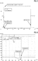
- FIG. 5 shows the malfunction in a faulty open counter electrode of an electrolytic gas sensor and its detection by the inventive method.
- a differential voltage applied between the reference and working electrodes is amplified and, based on this, the potential of the counterelectrode is regulated in such a way that this difference voltage becomes as small as possible.
- a measuring current which flows into the counterelectrode and which represents the gas concentration sets in approximately in proportion to a gas concentration of the gas to be detected.
- the counter voltage U G is detected on an impermissible deviation from the ground potential, wherein the counter-voltage U G is within the normal error-free operation mode at about the -potential U off.
- the impermissible deviation is shown in the example of the present figure in a sudden increase of the counter voltage U G. This error typically occurs when the electrical connection between the counter electrode and the ground potential is interrupted, ie open. This invalid case is then output as an assigned error message.
- the right end of the FIG. 5 again shows the proper function of the gas sensor.
- FIG. 6 shows the time course of a malfunction in case of faulty short circuit of the working, reference and counter electrode with each other (no ground fault) and its detection by the inventive method.
- the measurement voltage U GAS corresponding to a current gas concentration breaks down abruptly.
- This impermissible change in the measuring voltage U G is then output as a second error message. In the present For example, this is the case when the error counter has counted down to the value 0 again.
- FIG. 7 shows by way of example a functional failure of an electrolytic gas sensor with impermissible deviation of the voltage difference between the working voltage and the reference voltage as at least one combination of the measuring, working, counter and reference voltage.
- an assigned third error message is output.
- the counter voltage U G changes abruptly to extreme voltage values with an unexplained speed of the sensor response time.
- the measuring voltage U GAS equalizes the offset voltage U OFF .
- the digital values corresponding to the offset voltage U OFF can be stored, for example, for monitoring in the microcontroller.
- the measuring voltage U GAS drops to extreme voltage values below the offset voltage U OFF , which is not possible during proper operation.
- the measuring voltage U GAS jumps briefly to extreme, not plausible values with subsequent recovery.
Description
Die vorliegende Erfindung betrifft ein Verfahren sowie eine Vorrichtung zur Funktionsüberwachung eines elektrolytischen, auf ein spezifisches Gas empfindlichen Gassensors mit drei Elektroden, insbesondere mit einer Arbeits-, Referenz- und Gegenelektrode, auf elektrische Fehler wie Kurzschluss, Masseschluss und Unterbrüche der einzelnen Elektroden oder Kombinationen davon. Zur messtechnischen Ermittlung einer Gaskonzentration ist es dabei bekannt, eine zwischen der Referenz- und Arbeitselektrode anliegende Differenzspannung zu verstärken. Darauf basierend wird dann das Potential der Gegenelektrode derart geregelt, dass die Differenzspannung möglichst klein wird. Es stellt sich dabei ein in etwa proportional zu der Gaskonzentration des zu detektierenden Gases in die Gegenelektrode hineinfliessender Messstrom ein.The present invention relates to a method and a device for monitoring the function of an electrolytic, sensitive to a specific gas gas sensor with three electrodes, in particular with a working, reference and counter electrode, electrical faults such as short circuit, short to ground and interruptions of the individual electrodes or combinations thereof , For the metrological determination of a gas concentration, it is known to increase a voltage applied between the reference and working electrode differential voltage. Based on this, the potential of the counter electrode is then regulated in such a way that the differential voltage becomes as small as possible. In this case, an approximately proportional to the gas concentration of the gas to be detected in the counter electrode flowing into a measuring current turns.
Aus dem Stand der Technik sind zahlreiche Verfahren bekannt, die eine Überwachung des Gassensors erlauben, indem an die Elektroden des Gassensors z.B. ein Spannungspuls oder eine Pulsreihe angelegt wird und indem nachfolgend verschiedene elektrische Kenngrössen gemessen werden.Numerous methods are known in the prior art which permit monitoring of the gas sensor by applying to the electrodes of the gas sensor e.g. a voltage pulse or a pulse train is applied and by subsequently measuring various electrical parameters.
In der
Aus der
Aus der internationalen Veröffentlichung
Die Erfindung betrifft weiterhin einen Gefahrenmelder, der zumindest einen elektrolytischen, jeweils auf ein spezifisches Gas empfindlichen Gassensor und eine derartige Vorrichtung zur Funktionsüberwachung aufweist. Der Gefahrenmelder ist vorzugsweise ein Gasmelder, insbesondere ein CO-Gasmelder bzw. Kohlenstoffmonoxid-Gasmelder. Der Gefahrenmelder weist eine erste Ausgabeeinheit zur Ausgabe einer Warn- oder Alarmmeldung auf, wenn eine ermittelte jeweilige Gaskonzentration einen vorgegebenen Schwellwert oder einen von der jeweiligen Gaskonzentration zeitabhängigen Schwellwert überschreitet. Er weist eine zweite Ausgabeeinheit zur Ausgabe einer Fehlermeldung im Falle einer ermittelten Funktionsunfähigkeit des jeweiligen Gassensors auf.The invention further relates to a hazard detector which has at least one electrolytic gas sensor sensitive to a specific gas and such a device for monitoring function. The hazard detector is preferably a gas detector, in particular a CO gas detector or carbon monoxide gas detector. The hazard detector has a first output unit for outputting a warning or alarm message when a determined respective gas concentration exceeds a predetermined threshold value or a time value dependent on the respective gas concentration threshold value. It has a second output unit for outputting an error message in the event of a determined malfunction of the respective gas sensor.
Derartige typischerweise als Punktmelder ausgebildete Gefahrenmelder werden eingesetzt, um ein unerwünschtes Auftreten einer Gefahrensituation wie beispielsweise ein Austreten und/oder ein Entstehen eines gefährlichen Gases wie Kohlenmonoxid frühzeitig zu erkennen. Sie sind typischerweise in einem gefahrenüberwachten Bereich angebracht, wie z.B. an geeigneten Stellen innerhalb eines Gebäudes. Der Gefahrenmelder kann auch weitere Detektionseinheiten zur Gefahrenmeldung aufweisen, wie z.B. eine nach dem Streulichtverfahren arbeitende optische Detektionseinheit zur Detektion von Rauchpartikeln oder eine Temperaturdetektionseinheit zur Detektion von Hitze im Falle eines Brandes. Ein derartiger Gefahrenmelder wird auch als Multikriterien-Gefahrenmelder bezeichnet. Die jeweiligen Detektionssignale werden zur Reduzierungen von Fehlalarmen sowie zur zuverlässigeren Ausgabe einer detektierten Gefahr miteinander kombiniert.Such danger detectors, which are typically designed as point detectors, are used to detect an undesired occurrence of a dangerous situation, such as leakage and / or the emergence of a dangerous gas such as carbon monoxide, at an early stage. They are typically mounted in a hazard-monitored area, such as at appropriate locations within a building. The hazard detector can also have other detection units for hazard reporting, such as an operating according to the scattered light method optical detection unit for the detection of smoke particles or a temperature detection unit for the detection of heat in the event of a fire. Such a hazard detector is also referred to as a multi-criteria hazard detector. The respective detection signals are used to reduce False alarms and for more reliable output of a detected hazard combined.
Ein derartiger Gefahrenmelder kann auch ein Teil eines Gefahrenmeldesystems oder eines umfassenden Gebäudemanagementsystems sein, welches neben einer Zentrale mehrere als Peripheriegeräte ausgebildete Gefahrenmelder aufweist. Die Peripheriegeräte können mit der Zentrale über eine leitungsgebundene oder eine drahtlose Kommunikationsverbindung direkt oder eine indirekt verbunden sein.Such a hazard detector may also be a part of a hazard detection system or a comprehensive building management system, which in addition to a center has several trained as peripherals hazard detector. The peripheral devices may be directly or indirectly connected to the center via a wireline or wireless communication link.
Schliesslich betrifft die Erfindung ein Gasmessgerät mit zumindest einem elektrolytischen, jeweils auf ein spezifisches Gas empfindlichen Gassensor und mit einer derartigen Vorrichtung zur Funktionsüberwachung des jeweiligen Gassensors. Das Gasmessgerät weist eine Messausgabeeinheit zur Ausgabe einer jeweiligen Gaskonzentration und eine zweite Ausgabeeinheit zur Ausgabe einer Fehlermeldung im Falle einer ermittelten Funktionsunfähigkeit des jeweiligen Gassensors auf.Finally, the invention relates to a gas measuring device with at least one electrolytic, in each case sensitive to a specific gas gas sensor and with such a device for monitoring the function of the respective gas sensor. The gas measuring device has a measuring output unit for outputting a respective gas concentration and a second output unit for outputting an error message in the event of a determined functional inability of the respective gas sensor.
Ausgehend von dem eingangs genannten Stand der Technik ist es eine Aufgabe der Erfindung, ein Verfahren zur Funktionsüberwachung eines elektrolytischen Gassensors anzugeben, welches zuverlässig und besonders einfach zu realisieren ist und welches den Sensorbetrieb möglichst wenig beeinträchtigt.Based on the above-mentioned prior art, it is an object of the invention to provide a method for monitoring the operation of an electrolytic gas sensor, which is reliable and particularly easy to implement and which affects the sensor operation as little as possible.
Erfindungsgemäss wird unabhängig von der Ermittlung des Messstroms, welcher die Gaskonzentration repräsentiert, eine an den drei Elektroden anliegende Arbeits-, Gegen- und Referenzspannung erfasst und jeweils auf eine unzulässige Abweichung hin überwacht. In einem unzulässigen Fall wird dann eine zugeordnete Fehlermeldung ausgegeben.According to the invention, independently of the determination of the measuring current, which represents the gas concentration, a working, counter and reference voltage applied to the three electrodes is detected and monitored in each case for an impermissible deviation. In an invalid case, an associated error message is output.
Die Werte der erfassten Arbeits-, Gegen- und Referenzspannung können zudem jeweils mathematisch bewertet werden, wie z.B. gewichtet. Es werden dann die jeweiligen mathematischen Bewertungen auf eine jeweilige unzulässige Abweichung hin überwacht und dann in einem unzulässigen Fall eine zugeordnete Fehlermeldung ausgegeben.The values of the detected working, counter and reference voltages can also be mathematically evaluated, eg weighted. The respective mathematical evaluations are then monitored for a respective impermissible deviation and then issue an associated error message in an invalid case.
Dadurch ist vorteilhaft eine "Online"-Überwachung des elektrochemischen Gassensors möglich. Auf eine sonstige Unterbrechung des Messbetriebs, in welchem Spannungsimpulse, Impulsfolgen oder kleine Wechselspannungen an die Elektroden zu Testzwecken angelegt werden, kann verzichtet werden. Mit "Online"-Überwachung ist gemeint, dass alle Elektrodenspannungen zumindest in etwa zeitgleich erfasst und ausgewertet werden.As a result, an "online" monitoring of the electrochemical gas sensor is advantageously possible. On another interruption of the measuring operation, in which voltage pulses, pulse trains or small AC voltages are applied to the electrodes for test purposes, can be dispensed with. By "online" monitoring is meant that all electrode voltages are detected and evaluated at least approximately at the same time.
Darüber hinaus kann vorteilhaft auf zusätzlich erforderliche Bauelemente für die Realisierung des Testbetriebs, wie z.B. auf eine Wechselspannungsquelle bei der
Mit unzulässiger Abweichung einer Arbeits-, Gegen- und Referenzspannung ist die Abweichung eines aktuell erfassten Arbeits-, Gegen- und Referenzspannungswertes von einem jeweils vorgegebenen Vergleichsspannungswert gemeint, und zwar nach "oben" und/oder nach "unten", d.h. wenn der jeweilige obere Vergleichsspannungswert überschritten wird und/oder wenn der jeweilige untere Vergleichsspannungswert unterschritten wird.With an impermissible deviation of a working, counter and reference voltage is meant the deviation of a currently detected working, counter and reference voltage value from a respective predetermined reference voltage value, namely "up" and / or "down", i. if the respective upper reference voltage value is exceeded and / or if the respective lower reference voltage value is undershot.
Die Ausgabe der Fehlermeldung kann auf optischem Wege, wie z.B. mittels eines Lichtsignals, erfolgen. Die Ausgabe kann alternativ oder zusätzlich auf akustischem Wege erfolgen, wie z.B. mittels eines Warntons. Die Fehlermeldung kann alternativ oder zusätzlich an eine übergeordnete Zentrale ausgegeben werden. Die Fehlermeldung kann alternativ oder zusätzlich leitungsgebunden oder drahtlos, wie z.B. mittels Funk, mittels Ultraschall oder mittels Infrarot, ausgegeben werden.The output of the error message may be transmitted by optical means, e.g. by means of a light signal. The output may alternatively or additionally be acoustical, e.g. by means of a warning tone. The error message can alternatively or additionally be output to a higher-level control center. The error message may alternatively or additionally be wired or wireless, e.g. by radio, by means of ultrasound or by means of infrared.
Die (erste) Fehlermeldung kann eine Sammelmeldung sein, welche anzeigt, dass einer der aktuell erfassten Arbeits-, Gegen- und Referenzspannungswerte von einem jeweils vorgegebenen Vergleichsspannungswert in unzulässiger Weise abgewichen ist. Im einfachsten Falle ist diese Fehlermeldung lediglich eine binäre Information. Die Fehlermeldung kann auch kodiert sein, so dass individuell die jeweilige unzulässige Abweichung angezeigt werden kann.The (first) error message can be a collective message which indicates that one of the currently detected working, counter and reference voltage values is from a given one The reference voltage value has deviated in an inadmissible way. In the simplest case, this error message is merely binary information. The error message can also be coded so that the respective impermissible deviation can be displayed individually.
Nach einer bevorzugten Verfahrensvariante wird der Messstrom zuerst in eine dazu proportionale Messspannung umgewandelt, wobei dann diese Messspannung die dazu in etwa proportionale Gaskonzentration repräsentiert. Die dadurch einfacher mögliche messtechnische Erfassung wird mittels eines Transimpedanzwandlers bzw. vorzugsweise mittels eines Transimpedanzverstärkers realisiert.According to a preferred variant of the method, the measuring current is first converted into a proportional measuring voltage, in which case this measuring voltage represents the gas concentration which is approximately proportional thereto. The thereby simpler possible metrological detection is realized by means of a transimpedance transducer or preferably by means of a transimpedance amplifier.
Einer weiteren Verfahrensvariante zufolge wird eine Warn- oder Alarmmeldung ausgegeben, wenn die die Gaskonzentration repräsentierende Messspannung einen vorgegebenen Schwellwert oder einen von der Gaskonzentration zeitabhängigen Schwellwert über- oder unterschreitet. Derartige Schwellwerte sind z.B. in Europa nach der Norm EN 50291 für die Detektion von Kohlenmonoxid (CO) in Wohnhäusern für Gasmelder vorgegeben. Demnach ist z.B. bei Detektion einer CO-Gaskonzentration von 330 ± 30 ppm innerhalb von 3 Minuten zu alarmieren, während z.B. bei Detektion einer CO-Gaskonzentration von 33 ± 3 ppm frühestens nach 120 Minuten eine Alarmierung erfolgen darf. In ähnlicher Weise regelt die in den USA gültige Norm UL 2034 die Alarmierungsbedingungen für CO-Gasmelder.According to a further variant of the method, a warning or alarm message is output if the measuring voltage representing the gas concentration exceeds or falls below a predetermined threshold value or a threshold value dependent on the gas concentration. Such thresholds are e.g. specified in Europe according to the standard EN 50291 for the detection of carbon monoxide (CO) in homes for gas detectors. Thus, e.g. upon detection of a CO gas concentration of 330 ± 30 ppm within 3 minutes, while e.g. upon detection of a CO gas concentration of 33 ± 3 ppm, an alarm must be given at the earliest after 120 minutes. Similarly, the US standard UL 2034 regulates alarm conditions for CO gas detectors.
Natürlich können für andere zu detektierende Gase, wie z.B. von Kohlenstoffdioxid (CO2), Ethanol oder Methan, andere Schwellwerte vorgegeben sein. Es kann auch bei Erreichen eines einzigen Schwellwertes sofort eine Alarmierung erfolgen.Of course, for other gases to be detected, such as carbon dioxide (CO 2 ), ethanol or methane, other thresholds may be specified. Even if a single threshold value is reached, an alarm can be issued immediately.
Nach einer weiteren Verfahrensvariante wird die Messspannung auf eine unzulässige Spannungsabweichung hin überwacht. Es wird dann in einem unzulässigen Fall eine zugeordnete zweite Fehlermeldung ausgegeben. Dies ist z.B. dann der Fall, wenn die Messspannung einen negativen Spannungswert aufweisen sollte oder wenn die Messspannung einen positiven Spannungswert aufweisen sollte, der einen vorgegebenen minimalen oder maximalen Vergleichswert unter- bzw. überschreitet.According to another variant of the method, the measuring voltage is monitored for an impermissible voltage deviation. An assigned second error message is then output in an inadmissible case. This is the case, for example, when the measuring voltage has a negative voltage value should or should the measurement voltage have a positive voltage value that falls below or exceeds a predetermined minimum or maximum reference value.
Die zweite Fehlermeldung kann auch ausgegeben werden, wenn sich die Messspannung sprungartig ändert, wobei eine derartige zeitliche Änderung nicht plausibel mit einer physikalischen Änderung der Gaskonzentration ist bzw. nicht der Sensorantwort entspricht. Zum Beispiel darf die Änderung des Ausgangssignals des CO-Sensorverstärkers nicht innerhalb von 1 bis 2 Messzyklen von einem Ruhewert auf den Maximalwert ansteigen. Selbiges trifft auf einen Abfall von einem Maximalwert auf einen Ruhewert zu.The second error message can also be output if the measuring voltage changes abruptly, such a temporal change not being plausible with a physical change in the gas concentration or not corresponding to the sensor response. For example, the change in the output signal of the CO sensor amplifier must not rise from a quiescent value to the maximum value within 1 to 2 measurement cycles. The same applies to a fall from a maximum value to a resting value.
Einer weiteren Verfahrensvariante zufolge wird zumindest eine Kombination aus der Mess-, Arbeits-, Gegen- und Referenzspannung jeweils auf eine weitere unzulässige Abweichung hin überwacht. Es wird dann in einem unzulässigen Fall eine zugeordnete dritte Fehlermeldung ausgegeben. Dies kann die Überwachung einer Differenzspannung, wie z.B. die Differenzspannung zwischen der Referenz- und Gegenelektrode, auf eine unzulässige Abweichung hin sein. Die Kombination kann eine Addition, eine Subtraktion, eine gewichtete Addition oder Subtraktion sein. Es können prinzipiell für eine bewertete Kombination weitere mathematische Funktionen in Betracht gezogen werden, die eine zuverlässige bzw. zuverlässigere Detektion eines Fehlers erlauben.According to a further variant of the method, at least one combination of the measuring, working, counter and reference voltages is monitored in each case for a further impermissible deviation. An assigned third error message is then output in an impermissible case. This may involve the monitoring of a differential voltage, e.g. the difference voltage between the reference and counter electrode, to be an inadmissible deviation. The combination can be an addition, a subtraction, a weighted addition or a subtraction. In principle, additional mathematical functions can be considered for a weighted combination, which allow reliable or more reliable detection of a fault.
Die Aufgabe der Erfindung wird weiterhin durch eine zum erfindungsgemässen Verfahren korrespondierende Vorrichtung zur Funktionsüberwachung eines elektrolytischen, auf ein spezifisches Gas empfindlichen Gassensors mit einer Arbeits-, Referenz- und Gegenelektrode gelöst. Die Vorrichtung weist einen Potentiostaten zur Verstärkung einer zwischen der Referenz- und Arbeitselektrode anliegenden Differenzspannung sowie zur Regelung des Potentials der Gegenelektrode auf, so dass die Differenzspannung möglichst klein wird. Die Vorrichtung weist eine elektronische Verarbeitungseinheit zur Erfassung eines in die Gegenelektrode hineinfliessenden, sich in etwa proportional zu einer Gaskonzentration des zu detektierenden Gases einstellenden Messstroms auf. Die elektronische Verarbeitungseinheit ist zusätzlich dazu eingerichtet, unabhängig von der Ermittlung der Gaskonzentration eine jeweils an den drei Elektroden anliegende Arbeits-, Gegen- und Referenzspannung zu erfassen, jeweils auf eine unzulässige Abweichung hin zu überwachen und in einem unzulässigen Fall eine zugeordnete (erste) Fehlermeldung auszugeben.The object of the invention is further achieved by a corresponding method according to the invention for monitoring the function of an electrolytic, sensitive to a specific gas gas sensor with a working, reference and counter electrode. The device has a potentiostat for amplifying a voltage applied between the reference and working electrode differential voltage and for controlling the potential of the counter electrode, so that the differential voltage is as small as possible. The device has an electronic processing unit for detecting a in the counter electrode flowing into, in approximately proportional to a gas concentration of the gas to be detected adjusting measuring current. The electronic processing unit is additionally set up to detect, independently of the determination of the gas concentration, a respective working, counter and reference voltage applied to the three electrodes, in each case to monitor an impermissible deviation and in an impermissible case an associated (first) error message issue.
Die Funktionsweise eines Potentiostaten auf dem Gebiet der elektrolytischen Gassensorik ist aus dem Stand der Technik hinreichend bekannt. Die elektronische Verarbeitungseinheit ist vorzugsweise eine prozessorgestützte elektronische Verarbeitungseinheit, wie z.B. ein Mikrocontroller. Alternativ kann die elektronische Verarbeitungseinheit auch "analog" realisiert sein, wie z.B. durch mehrere Fensterkomparatoren für die Detektion der jeweiligen unzulässigen Abweichung und ggf. durch ein oder mehrere nachgeschaltete Logikgatter für die Ausgabe eines digitalen Signals für die Fehlermeldung.The operation of a potentiostat in the field of electrolytic gas sensors is well known in the art. The electronic processing unit is preferably a processor-based electronic processing unit, e.g. a microcontroller. Alternatively, the electronic processing unit may also be realized "analog", e.g. by several window comparators for the detection of the respective impermissible deviation and possibly by one or more downstream logic gates for the output of a digital signal for the error message.
Nach einer bevorzugten Ausführungsform weist die Vorrichtung einen Transimpedanzverstärker zur Umwandlung des Messstroms in eine dazu proportionale Messspannung sowie die elektronische Verarbeitungseinheit zur Erfassung der dann die Gaskonzentration repräsentierenden Messspannung auf. Durch die Verstärkung und Impedanzwandlung vereinfacht sich die nachfolgende spannungsbasierte Messwerterfassung erheblich.According to a preferred embodiment, the device has a transimpedance amplifier for converting the measuring current into a measuring voltage proportional thereto and the electronic processing unit for detecting the measuring voltage then representing the gas concentration. Due to the gain and impedance conversion, the subsequent voltage-based measured value acquisition is simplified considerably.
Einer weiteren Ausführungsform zufolge ist die elektronische Verarbeitungseinheit dazu eingerichtet, die Messspannung auf eine unzulässige Spannungsabweichung hin zu überwachen und in einem unzulässigen Fall eine zugeordnete zweite Fehlermeldung auszugeben.According to a further embodiment, the electronic processing unit is adapted to monitor the measuring voltage for an impermissible voltage deviation and to output an associated second error message in an impermissible case.
Vorzugsweise weisen die Messspannung sowie die Arbeits-, Gegen- und Referenzspannung ein gemeinsames Bezugspotential auf. Dieses Bezugspotential ist typischerweise die Masse.Preferably, the measuring voltage and the working, counter and reference voltage have a common reference potential. This reference potential is typically the ground.
Nach einer weiteren vorteilhaften Ausführungsform weist die Verarbeitungseinheit einen A/D-Umsetzer zur Umsetzung der Messspannung sowie der Arbeits-, Gegen- und Referenzspannung in entsprechende Digitalwerte auf. Alternativ kann die Verarbeitungseinheit auch mit einem A/D-Umsetzer datentechnisch verbunden sein. Der A/D-Umsetzer ist vorzugsweise mehrkanalig ausgeführt, wie z.B. vier- oder achtkanalig, so dass die zu erfassende Messspannung und die Elektrodenspannungen parallel, d.h. gleichzeitig, erfasst werden können. Die Verarbeitungseinheit ist dazu eingerichtet, die Digitalwerte jeweils auf einen der unzulässigen Abweichung entsprechenden Digitalwert hin zu überwachen und in einem unzulässigen Fall die jeweilige zugeordnete Fehlermeldung auszugeben.According to a further advantageous embodiment, the processing unit has an A / D converter for converting the measuring voltage and the working, counter and reference voltage into corresponding digital values. Alternatively, the processing unit may also be connected to an A / D converter in terms of data technology. The A / D converter is preferably multi-channeled, e.g. four- or eight-channel, so that the measured voltage to be detected and the electrode voltages in parallel, i. at the same time, can be recorded. The processing unit is set up to monitor the digital values for a digital value corresponding to the impermissible deviation and to output the respective associated error message in an impermissible case.
Vorzugsweise ist die elektronische Verarbeitungseinheit ein Mikrocontroller. Derartige Bauelemente weisen typischerweise bereits einen mehrkanaligen A/D-Umsetzer sowie weitere analoge und digitale Ein- und Ausgänge auf. Die Digitalwerte, welche den jeweiligen unzulässigen Abweichungen entsprechen, sind vorzugsweise als Datenwerte in einem nichtflüchtigen Datenspeicher des Mikrocontrollers abgelegt. Der Vergleich der umgesetzten Digitalwerte, der digitale Vergleich dieser auf eine unzulässige Abweichung hin sowie die Ausgabe der zweiten Fehlermeldung erfolgt mit programmtechnischen Mitteln, d.h. mittels eines auf dem Mikrocontroller ausgeführten geeigneten Computerprogramms.Preferably, the electronic processing unit is a microcontroller. Such components typically already have a multi-channel A / D converter and other analog and digital inputs and outputs. The digital values which correspond to the respective impermissible deviations are preferably stored as data values in a nonvolatile data memory of the microcontroller. The comparison of the converted digital values, the digital comparison of these on an impermissible deviation as well as the output of the second error message is carried out by program means, i. by means of a suitable computer program executed on the microcontroller.
Einer weiteren Ausführungsform zufolge ist die Verarbeitungseinheit dazu eingerichtet, zumindest eine Kombination aus je zwei der Mess-, Arbeits-, Gegen- und Referenzspannung entsprechenden Digitalwerten jeweils auf eine weitere unzulässige Abweichung hin zu überwachen und in einem unzulässigen Fall eine zugeordnete dritte Fehlermeldung auszugeben.According to another embodiment, the processing unit is set up to monitor at least one combination of two digital values corresponding to each of the measurement, operating, counter and reference voltages for a further impermissible deviation and to output an assigned third error message in an impermissible case.
Nach einer bevorzugten Ausführungsform sind die Messspannung sowie die Arbeits-, Gegen- und Referenzspannung mittels des A/D-Umsetzers zumindest in etwa zeitgleich mit einer Abtastrate in einem Bereich von 0.25 bis 4 Hertz in die entsprechenden Digitalwerte umsetzbar. Da die digitale Umsetzung der erfassten Eingangsspannungen an dem A/D-Umsetzer sowie der rechnerische Vergleich und ggf. die Generierung einer Fehlermeldung typischerweise nur wenige Millisekunden beträgt, benötigt der Mikrocontroller nur für diese kurze zyklischen Phasen eine signifikante elektrische Leistung, während er in den überwiegenden Pausenphasen nur eine geringe vernachlässigbaren Ruheleistung benötigt. Dadurch ist ein batteriegestützter Betrieb eines Gefahrenmelders über mehrere Jahre hinweg vorteilhaft möglich.According to a preferred embodiment, the measuring voltage as well as the working, counter and reference voltage by means of the A / D converter at least approximately at the same time with a sampling rate in a range of 0.25 to 4 Hertz in the corresponding Digital values can be implemented. Since the digital conversion of the detected input voltages at the A / D converter as well as the computational comparison and possibly the generation of an error message is typically only a few milliseconds, the microcontroller requires significant electrical power only for these short cyclic phases, while in the vast majority of cases Pausenphasen only a small negligible quiescent power needed. As a result, a battery-powered operation of a hazard alarm over several years is advantageously possible.
Einer weiteren, besonders vorteilhaften Ausführungsform weist die Vorrichtung ein dem A/D-Umsetzer vorgeschaltetes Tiefpass-Rauschfilter zur Filterung der Messspannung mit einer Eckfrequenz von weniger als 10 Hertz, insbesondere von weniger als 1 Hertz auf Hertz, auf.In a further, particularly advantageous embodiment, the device has a low-pass noise filter connected upstream of the A / D converter for filtering the measurement voltage with a cut-off frequency of less than 10 hertz, in particular less than 1 hertz to hertz.
Durch die Glättung der Messspannung ist eine vergleichsweise langsame leistungssparende A/D-Umsetzung möglich. Dagegen benötigt eine vergleichsweise hochfrequente A/D-Umsetzung im Bereich von mehreren Kilohertz mit nachgeschaltem Digitalfilter ein Vielfaches der elektrischen Leistung, um den hohen Rauschanteil in der Messspannung wieder zu eliminieren.By smoothing the measuring voltage, a comparatively slow power-saving A / D conversion is possible. In contrast, a comparatively high-frequency A / D conversion in the range of several kilohertz with a downstream digital filter requires a multiple of the electrical power in order to eliminate the high noise component in the measuring voltage again.
Die Aufgabe der Erfindung wird weiterhin durch einen Gefahrenmelder mit zumindest einem elektrolytischen, jeweils auf ein spezifisches Gas empfindlichen Gassensor gelöst. Der Gefahrenmelder weist dabei eine erfindungsgemässe Vorrichtung zur Funktionsüberwachung des jeweiligen Gassensors auf. Der Gefahrenmelder weist weiterhin eine erste Ausgabeeinheit zur Ausgabe einer Warn- oder Alarmmeldung auf, wenn eine jeweilige ermittelte Gaskonzentration einen vorgegebenen Schwellwert oder einen von der jeweiligen Gaskonzentration zeitabhängigen Schwellwert über- oder unterschreitet. Er weist zudem eine zweite Ausgabeeinheit zur Ausgabe einer Fehlermeldung im Falle einer ermittelten Funktionsunfähigkeit des jeweiligen Gassensors auf.The object of the invention is further achieved by a hazard detector with at least one electrolytic, in each case sensitive to a specific gas sensor. The hazard detector has an inventive device for monitoring the function of the respective gas sensor. The hazard detector furthermore has a first output unit for outputting a warning or alarm message when a respective determined gas concentration exceeds or falls below a predetermined threshold value or a threshold value that is time-dependent on the respective gas concentration. It also has a second output unit for outputting an error message in the event of a determined malfunction of the respective gas sensor.
Die Ausgabe der Fehlermeldung kann auf optischem Wege, wie z.B. mittels einer blinkenden LED des Gefahrenmelders, erfolgen. Die Ausgabe kann alternativ oder zusätzlich auf akustischem Wege erfolgen, wie z.B. mittels eines Lautsprechers oder eines Buzzers des Gefahrenmelders. Die Fehlermeldung kann alternativ oder zusätzlich über eine Kommunikationsschnittstelle des Gefahrenmelders an eine übergeordnete Zentrale erfolgen. Die Kommunikationsschnittstelle kann zur drahtgebunden Ausgabe der Fehlermeldung eingerichtet sein, wie z.B. an einen angeschlossenen Melderbus. Alternativ oder zusätzlich kann die Kommunikationsschnittstelle zur drahtlosen Ausgabe der Fehlermeldung eingerichtet sein. In diesem Fall kann die Kommunikationsschnittstelle eine Funkschnittstelle, eine Ultraschallschnittstelle oder eine Infrarot-Schnittstelle sein. Die beiden Ausgabeeinheiten können selbstverständlich auch in einer gemeinsamen Ausgabeeinheit zusammengefasst sein.The output of the error message may be transmitted by optical means, e.g. by means of a flashing LED of the danger detector. The output may alternatively or additionally be acoustical, e.g. by means of a loudspeaker or a buzzer of the danger detector. Alternatively or additionally, the error message can occur via a communication interface of the hazard alarm to a higher-level control center. The communication interface may be configured for wired output of the error message, e.g. to a connected detector bus. Alternatively or additionally, the communication interface for wireless output of the error message can be set up. In this case, the communication interface may be a radio interface, an ultrasound interface or an infrared interface. Of course, the two output units can also be combined in a common output unit.
Die Aufgabe der Erfindung wird weiterhin durch ein Gasmessgerät gelöst, welches zumindest einen elektrolytischen, jeweils auf ein spezifisches Gas empfindlichen Gassensor und eine erfindungsgemässe Vorrichtung zur Funktionsüberwachung des jeweiligen Gassensors aufweist. Das Gasmessgerät weist eine Messausgabeeinheit zur Ausgabe einer jeweiligen Gaskonzentration und eine zweite Ausgabeeinheit zur Ausgabe einer Fehlermeldung im Falle einer ermittelten Funktionsunfähigkeit des jeweiligen Gassensors auf.The object of the invention is further achieved by a gas measuring instrument which has at least one electrolytic gas sensor sensitive to a specific gas and an apparatus according to the invention for monitoring the function of the respective gas sensor. The gas measuring device has a measuring output unit for outputting a respective gas concentration and a second output unit for outputting an error message in the event of a determined functional inability of the respective gas sensor.
Der Konzentrationswert kann als analoges Signal, wie z.B. in Form eines analogen Strom- oder Spannungssignals, oder als digitales Signal ausgegeben werden, wie z.B. digital kodiert oder pulsweitenmoduliert. Im einfachsten Fall ist der Konzentrationswert ein Prozentwert, ein Promillewert oder ein Zahlenwert in ppm (für parts per million). Der Konzentrationswert kann für jedes zu detektierende Gas zugeordnet ausgegeben werden. Die Ausgabe des Konzentrationswerts kann auf einer Anzeigeeinheit, wie z.B. auf einem LCD, des Gasmessgeräts als Zahlenwert ausgegeben werden. Er kann alternativ oder zusätzlich über eine Kommunikationsschnittstelle an eine (zentrale) Messstation ausgegeben werden, wie z.B. über ein Datenkabel oder drahtlos, wie z.B. über Funk oder Infrarot.The concentration value can be output as an analog signal, such as in the form of an analog current or voltage signal, or as a digital signal, such as digitally encoded or pulse width modulated. In the simplest case, the concentration value is a percentage, a per mille value or a numerical value in ppm (for parts per million). The concentration value can be output assigned for each gas to be detected. The output of the concentration value may be output on a display unit such as an LCD of the gas meter as a numerical value. He can alternatively or additionally via a communication interface to a (central) measuring station output, such as via a data cable or wirelessly, such as via radio or infrared.
Die Ausgabe der Fehlermeldung kann wie zuvor bei dem Gefahrenmelder beschrieben, erfolgen. Alternativ oder zusätzlich kann die Fehlermeldung auf der Anzeigeeinheit des Gasmessgerätes ausgegeben werden. Die beiden Ausgabeeinheiten können wiederum in einer gemeinsamen Ausgabeeinheit zusammengefasst sein.The output of the error message can be as described above for the hazard alarm. Alternatively or additionally, the error message can be output on the display unit of the gas meter. The two output units can in turn be combined in a common output unit.
Die Erfindung sowie vorteilhafte Ausführungen der vorliegenden Erfindung sind am Beispiel der nachfolgenden Figuren ersichtlich. Dabei zeigen
- FIG 1
- ein Beispiel für eine Vorrichtung zur Funktionsüberwachung eines elektrolytischen Gassensors mit drei Elektroden gemäss der Erfindung,
- FIG 2
- eine Ausführungsform der Vorrichtung nach
FIG 1 gemäss der Erfindung, - FIG 3
- einen beispielhaften Gefahrenmelder mit zwei Gassensoren, einem optischen Detektor, einem Temperatursensor und je einer Vorrichtung zur Funktionsüberwachung der Gassensoren gemäss der Erfindung,
- FIG 4
- ein beispielhaftes Gasmessgerät mit drei Gassensoren und mit je einer Vorrichtung zur Funktionsüberwachung der Gassensoren gemäss der Erfindung, und
- FIG 5 - FIG 7
- jeweils einen Funktionsausfall eines elektrolytischen Gassensors und der Detektion durch das erfindungsgemässe Verfahren.
- FIG. 1
- an example of a device for monitoring the operation of a three-electrode electrolytic gas sensor according to the invention,
- FIG. 2
- an embodiment of the device according to
FIG. 1 according to the invention, - FIG. 3
- an exemplary hazard detector with two gas sensors, an optical detector, a temperature sensor and a respective device for monitoring the function of the gas sensors according to the invention,
- FIG. 4
- an exemplary gas meter with three gas sensors and each with a device for monitoring the function of the gas sensors according to the invention, and
- FIG. 5 - FIG. 7
- in each case a malfunction of an electrolytic gas sensor and the detection by the inventive method.
Der zu überwachende, auf ein spezifisches Gas empfindliche elektrolytische Gassensor 2 weist eine Arbeits-, Referenz- und Gegenelektrode 21, 22, 23 auf. Der Gassensor 2 kann z.B. auf Kohlenmonoxid, Methan, Wasserstoff, Ammoniak, Wasserstoffsulfid, Stickstoffdioxid usw. empfindlich sein. Die Vorrichtung 1 weist weiterhin einen aus der elektrolytischen Gasanalyse bekannten Potentiostaten 3 auf, der zur Verstärkung einer zwischen der Referenz- und Arbeitselektrode 22, 21 anliegenden Differenzspannung dU sowie zur Regelung des Potentials der Gegenelektrode 23 vorgesehen ist, so dass die Differenzspannung dU möglichst klein wird. Der Potentiostat 3 umfasst einen Operationsverstärker 31, dessen Ausgang über einen Kondensator 33 mit dessen invertierenden Eingang verbunden ist. Der invertierende Eingang ist zudem über einen Widerstand 32 an der Referenzelektrode 22 angeschlossen. Ausgangsseitig stellt sich dann ein in die Gegenelektrode 23 hineinfliessender Messstrom iGAS ein, der in etwa proportional zu einer Gaskonzentration GAS des zu detektierenden Gases ist. Prinzipiell ist dieser Messstrom iGAS über eine Strommesseinrichtung erfassbar. Der Stromwertebereich liegt dabei typischerweise im Mikro- und Nanoampere-Bereich und ist folglich messtechnisch schwierig zu erfassen.The to be monitored, sensitive to a specific gas
Im Beispiel der vorliegenden
Weiterhin weist die Vorrichtung 1 eine elektronische Verarbeitungseinheit 5 mit einer analogen Messerfassungseinheit 51 auf. Letztere ist zur Erfassung des in die Gegenelektrode 23 hineinfliessenden Messstroms iGAS bzw. zur Erfassung der bereits mittels des Transimpendanzverstärkers 4 umgesetzten Messspannung UGAS eingerichtet. Erfindungsgemäss ist die Verarbeitungseinheit 5 bzw. die analoge Messerfassungseinheit 51 dazu eingerichtet, unabhängig von der Ermittlung der Gaskonzentration GAS eine jeweils an den drei Elektroden 21-23 anliegende Arbeits-, Gegen- und Referenzspannung UA, UG, UR zu erfassen und jeweils auf eine unzulässige Abweichung ΔUA, ΔUG, ΔUR hin zu überwachen. Prinzipiell weisen die Messspannung UGAS sowie die Arbeits-, Gegen- und Referenzspannung UA, UG, UR ein gemeinsames Bezugspotential GND auf. Mit anderen Worten sind die zuvor genannten Spannungen UGAS, UA, UG, UR allesamt auf ein gemeinsames Potential, typischerweise auf die gemeinsame Masse, d.h. dem Massepotential bezogen.Furthermore, the
Die analoge Messerfassungseinheit 51 kann aus mehreren Fensterkomparatoren für die Detektion der jeweiligen unzulässigen Abweichung ΔUA, ΔUG, ΔUR und ggf. durch ein oder mehrere nachgeschaltete Logikgatter für die Ausgabe eines digitalen Signals für eine entsprechende zugeordnete Fehlermeldung F realisiert sein. Sie kann zudem dazu eingerichtet sein, auch die Messspannung UGAS auf eine unzulässige Spannungsabweichung ΔUGAs hin zu überwachen und in einem unzulässigen Fall eine zugeordnete zweite Fehlermeldung FGAS auszugeben.The analog
Mit A1 bis A4 sind die jeweiligen Messeingänge bezeichnet. Es kann z.B. jeweils ein Fensterkomparator für die Diskriminierung der Messspannung UGAS sowie der Elektrodenspannungen UA, UG, UR vorgesehen sein. Ein Fensterkomparator kann z.B. durch zwei als Komparatoren beschaltete Operationsverstärker mit entsprechender Widerstandsbeschaltung realisiert sein.With A1 to A4 the respective measuring inputs are designated. For example, one window comparator each may be provided for discriminating the measuring voltage U GAS and the electrode voltages U A , U G , U R. A window comparator can be realized, for example, by two operational amplifiers connected as comparators with corresponding resistance circuitry.
Die Verarbeitungseinheit 5 bzw. die analoge Messerfassungseinheit 51 kann zudem dazu eingerichtet sein, eine Warn- oder Alarmmeldung WARN, AL auszugeben, wenn die die Gaskonzentration GAS repräsentierende Messspannung UGAS einen vorgegebenen Schwellwert oder einen von der Gaskonzentration GAS zeitabhängigen Schwellwert überschreitet. Auch in diesem Fall dann die analoge Messerfassungseinheit 51 einen oder mehrere Fensterkomparatoren sowie analoge Zeitglieder und ggf. ein oder mehrere nachgeschaltete Logikgatter für die digitale Ausgabe der Warn- oder Alarmmeldung WARN, AL aufweisen.The
Ferner kann die Verarbeitungseinheit 5 bzw. die analoge Messerfassungseinheit 51 dazu eingerichtet sein, zumindest eine Kombination aus der Mess-, Arbeits-, Gegen- und Referenzspannung UGAS, UA, UG, UR jeweils auf eine weitere unzulässige Abweichung hin zu überwachen und dann in einem unzulässigen Fall eine zugeordnete dritte Fehlermeldung auszugeben. Eine mögliche Kombination kann z.B. die Differenz oder die Summe aus jeweils zwei der zuvor genannten Spannungen UGAS, UA, UG, UR sein. Die technische Realisierung kann mit Hilfe von Fensterkomparatoren sowie mit analogen Addierern und Subtrahierern und ggf. weiterer nachgeschalteter Logikgattern erfolgen.Furthermore, the
Schliesslich kann die gezeigte Vorrichtung 1 einen Tiefpass-Rauschfilter 46 zur Filterung der Messspannung UGAS aufweisen. Vorzugsweise liegt die Eckfrequenz des Rauschfilters 46 in einem Bereich von 0.1 bis 10 Hertz. Das gezeigte Tiefpass-Rauschfilter 46 ist z.B. als RC-Filter erster Ordnung realisiert.Finally, the
Darüber hinaus kann der Mikrocontroller 5 dazu eingerichtet sein bzw. ein geeignetes (weiteres) Computerprogramm PRG aufweisen, um eine Warn- oder Alarmmeldung WARN, AL auszugeben, wenn eine jeweilige ermittelte Gaskonzentration GAS einen vorgegebenen Schwellwert oder einen von der jeweiligen Gaskonzentration GAS zeitabhängigen Schwellwert überschreitet. Es können z.B. mit steigender Gaskonzentration GAS vor der Ausgabe der Alarmmeldung AL auch eine oder mehrere Vorwarnmeldungen WARN ausgegeben werden. Schliesslich kann der Mikrocontroller 5 dazu eingerichtet sein, eine Fehlermeldung F, FGAS auszugeben, falls die Funktionsunfähigkeit des jeweiligen zu überwachenden Gassensors 2 festgestellt worden ist.In addition, the
Der gezeigte Gefahrenmelder 10 kann auch als Multikriterienmelder bezeichnet werden, bei dem für die Detektion einer Gefahr, wie z.B. eines Brandes, mehrere messtechnisch erfasste Eingangsgrössen miteinander kombiniert werden, um die Zuverlässigkeit einer Gefahrendetektion zu erhöhen und um Fehlalarme zu minimieren.The
Der Gefahrenmelder 10 weist eine Busschnittstelle 17 zur möglichen Ausgabe der ermittelten Fehler bzw. Fehlermeldungen F, FGAS sowie der Warn- und Alarmmeldungen WARN, AL auf einen angeschlossenen Melderbus BUS auf. Der Melderbus BUS ist typischerweise mit einer nicht gezeigten Gefahrenmeldezentrale zur Verarbeitung der eingehenden Meldungen F, FGAS, AL, WARN und zur Einleitung entsprechender Gegenmassnahmen angeschlossen. Die Gegenmassnahmen können z.B. die Weiterleitung eines gemeldeten Gasalarms an die Feuerwehr oder die Aufforderung eines Tausches des funktionsunfähig gemeldeten Gefahrenmelders an das Servicepersonal sein.The
Alternativ oder zusätzlich kann die Ausgabe der zuvor genannten Warn- und Alarmmeldungen WARN, AL an eine optische Ausgabeeinheit 13, wie z.B. an eine Blitzleuchte, und/oder an eine akustische Ausgabeeinheit 14, wie z.B. an einen Sounder oder Buzzer, erfolgen. Im vorliegenden Beispiel weist der Gefahrenmelder 10 eine weitere optische Ausgabeeinheit 15, wie z.B. eine LED, zur Ausgabe der Fehlermeldung F, FGAS an. Eine z.B. rot blinkende LED 15 kann dann eine im Umfeld des Gefahrenmelders anwesende Person auf eine festgestellte Funktionsunfähigkeit des Gefahrenmelders 10 informieren.Alternatively or additionally, the output of the aforementioned warning and alarm messages WARN, AL to an
Im vorliegenden Beispiel ist der gezeigte Mikrocontroller 5 dazu eingerichtet, zwei erfindungsgemässe Vorrichtungen 1 zur Funktionsüberwachung des jeweiligen Gassensors sowie einen optischen Detektor 11 für die Rauchdetektion sowie einen Temperaturdetektor 12 für die Übertemperaturdetektion gleichzeitig zu steuern und zu kontrollieren.In the present example, the
Der gezeigte Gasmelder 20 weist eine Busschnittstelle 17 zur Ausgabe der ermittelten digitalen Gaskonzentrationswerte DGAS sowie zur Ausgabe etwaiger Fehler bzw. Fehlermeldungen F, FGAS an einen angeschlossenen Datenbus DATA auf. An letzterem können weitere Gasmelder 20 oder z.B. ein Messauswerte-PC oder eine Prozesssteuergerät angeschlossen sein.The
Alternativ oder zusätzlich kann die Ausgabe der ermittelten digitalen Gaskonzentrationswerte DGAS auf einem Display 16 erfolgen, wie z.B. auf einem LCD. Es kann weiterhin alternativ oder zusätzlich die Ausgabe der Fehler bzw. Fehlermeldungen F, FGAS an eine optische Ausgabeeinheit 15 und/oder auf das Display 16 erfolgen. Im letzteren Fall können auch konkrete Angaben zu dem ermittelten Fehler F, FGAS ausgeben werden, wie z.B. "Ausfall Gassensors 2: Masseschluss detektiert!"Alternatively or additionally, the output of the determined digital gas concentration values DGAS can be made on a
Im gezeigten Zeitdiagramm sind über der Ordinate sogenannte "Counts" aufgetragen. Diese entsprechen dem jeweiligen Digitalwert der mittels eines ADCs umgesetzten analogen, gestrichelt eingetragenen Gegenspannung UG. Über der Abszisse ist die Zeit in Minuteneinheiten aufgetragen. Durchgezogen eingetragen ist zur Information der zeitliche Verlauf des Zählerstandes eines Fehlerzählers. Dieser wird für jeden auftretenden Fehler um einen Zählerwert verringert. Bei einem Zählerstand von 0 erfolgt die Ausgabe eines Fehlers. Durch das einstellbare "Herunterzählen" wird erreicht, dass kurzzeitig auftretende Fehler in der Messkette nicht zu einer sofortigen Fehlerauslösung beitragen, sondern erst eine gewisse vorgegebene Anzahl von Fehlerereignissen erreicht sein muss.In the time diagram shown so-called "counts" are plotted above the ordinate. These correspond to the respective digital value of the analog, dashed counter voltage U G converted by means of an ADC. The abscissa shows the time in minutes. Traced is entered for information the time course of the count of an error counter. This value is reduced by one counter value for each occurring error. With a count of 0, the output of an error takes place. The adjustable "counting down" ensures that short-term errors in the measuring chain do not contribute to an immediate triggering of the error, but that a certain predetermined number of error events must first be achieved.
Im normalen fehlerfreien Betriebsmodus wird eine zwischen der Referenz- und Arbeitselektrode anliegende Differenzspannung verstärkt und darauf basierend das Potential der Gegenelektrode derart geregelt, dass diese Differenzspannung möglichst klein wird. Daraufhin stellt sich ein in etwa proportional zu einer Gaskonzentration des zu detektierenden Gases in die Gegenelektrode hineinfliessender Messstrom ein, welcher die Gaskonzentration repräsentiert. Gemäss der Erfindung wird nun unabhängig von der Ermittlung des Messstroms bzw. einer dazu proportionalen Messspannung eine jeweils an den drei Elektroden anliegende Arbeits-, Gegen- und Referenzspannung erfasst und jeweils auf eine unzulässige Abweichung hin überwacht.In the normal error-free operating mode, a differential voltage applied between the reference and working electrodes is amplified and, based on this, the potential of the counterelectrode is regulated in such a way that this difference voltage becomes as small as possible. Thereupon, a measuring current which flows into the counterelectrode and which represents the gas concentration sets in approximately in proportion to a gas concentration of the gas to be detected. According to the invention, regardless of the determination of the measuring current or a measuring voltage proportional thereto, a working, counter and reference voltage applied to the three electrodes is detected and monitored in each case for an impermissible deviation.
Im vorliegenden Fall wird die Gegenspannung UG auf eine unzulässige Abweichung gegenüber dem Massepotential erfasst, wobei die Gegenspannung UG im normalen fehlerfreien Betriebsmodus in etwa auf dem Uoff-Potential liegt. Die unzulässige Abweichung zeigt sich im Beispiel der vorliegenden Figur in einem sprunghaften Anstieg der Gegenspannung UG. Dieser Fehler tritt typischerweise dann in Erscheinung, wenn die elektrische Verbindung zwischen der Gegenelektrode und dem Massepotential unterbrochen, d.h. offen ist. Dieser unzulässige Fall wird dann als zugeordnete Fehlermeldung ausgegeben. Das rechte Ende der
Im Folgenden werden weitere eindeutig detektierbare Fehlerfälle beschrieben:In the following, further clearly detectable error cases are described:
Die Gegenspannung UG ändert sich sprunghaft zu extremen Spannungswerten mit einer nicht erklärbaren Geschwindigkeit der Sensor-Antwortzeit.The counter voltage U G changes abruptly to extreme voltage values with an unexplained speed of the sensor response time.
Die Spannungsdifferenzen aus Gegen- und Referenzspannung UG-UR sowie aus Arbeits- und Referenzspannung UA-UR driften ausserhalb definierter Grenzwerte, die im ordnungsgemässen Betrieb nicht verlassen werden.The voltage differences from counter and reference voltage U G -U R as well as from working and reference voltage U A -U R drift outside defined limit values which are not left during proper operation.
Die Messspannung UGAS gleicht sich der Offsetspannung UOFF an. Die der Offsetspannung UOFF entsprechenden Digitalwerte können z.B. zur Überwachung im Mikrocontroller hinterlegt sein.The measuring voltage U GAS equalizes the offset voltage U OFF . The digital values corresponding to the offset voltage U OFF can be stored, for example, for monitoring in the microcontroller.
Die Messspannung UGAS sinkt zu extremen Spannungswerten unter die Offsetspannung UOFF, was im ordnungsgemässen Betrieb nicht möglich ist.The measuring voltage U GAS drops to extreme voltage values below the offset voltage U OFF , which is not possible during proper operation.
Die Messspannung UGAS springt kurzzeitig zu extremen, nicht plausiblen Werten mit anschliessender Erholung.The measuring voltage U GAS jumps briefly to extreme, not plausible values with subsequent recovery.
Dies führt zu unzulässig hohem Stromverbrauch des Gassensors, so dass sich der Gefahrenmelder bzw. das Gasmessgerät abmeldet. Der Gassensor kann in diesem Fall nicht mehr mit ausreichend Strom für einen ordnungsgemässen Messbetrieb versorgt werden. Es kann alternativ oder zusätzlich eine weitere, vierte Fehlermeldung ausgegeben werden.This leads to unacceptably high power consumption of the gas sensor, so that the danger detector or the gas meter logs off. In this case, the gas sensor can no longer be supplied with sufficient current for a proper measuring operation. Alternatively or additionally, a further, fourth error message can be output.
- 11
- Vorrichtung zur FunktionsüberwachungDevice for function monitoring
- 22
- Gassensor, elektrolytischer GassensorGas sensor, electrolytic gas sensor
- 33
- Potentiostatpotentiostat
- 44
- TransimpedanzverstärkerTransimpedance amplifier
- 55
- elektronische Verarbeitungseinheit, Mikrocontrollerelectronic processing unit, microcontroller
- 1010
- Gefahrenmelder, Gasmelder, Rauchgasmelder, BrandmelderHazard detectors, gas detectors, smoke detectors, fire detectors
- 1111
- optische Detektionseinheitoptical detection unit
- 1212
- TemperaturdetektionseinheitTemperature detection unit
- 1313
- optische Ausgabeeinheit, Blitzleuchteoptical output unit, strobe light
- 1414
- akustische Ausgabeeinheit, Sounder, Sireneacoustic output unit, sounder, siren
- 1515
- optische Ausgabeeinheit, LEDoptical output unit, LED
- 1616
- Display, AnzeigeeinheitDisplay, display unit
- 1717
- Schnittstelle, BusschnittstelleInterface, bus interface
- 2020
- Gasmessgerätgas meter
- 2121
- Arbeitselektrodeworking electrode
- 2222
- Referenzelektrodereference electrode
- 2323
- Gegenelektrodecounter electrode
- 31, 4131, 41
- Operationsverstärkeroperational amplifiers
- 32, 42, 4332, 42, 43
- ohmscher Widerstandohmic resistance
- 33, 4433, 44
- Kondensator, KapazitätCapacitor, capacity
- 4545
- ReferenzspannungsquelleReference voltage source
- 4646
- Tiefpassfilter, RauschfilterLow-pass filter, noise filter
- 5050
- ADC, Analog-/Digital-UmsetzerADC, analog / digital converter
- 5151
- analoge Messerfassungseinheitanalogue measuring unit
- A1-A4A1-A4
- analoge Eingängeanalog inputs
- ALAL
- Alarmsignal, AlarmmeldungAlarm signal, alarm message
- BUSBUS
- Melderlinie, Melderbus, MelderschleifeDetector line, detector bus, detector loop
- COUNTSCOUNTS
- Fehlerzählererror count
- dUyou
- Differenzspannungdifferential voltage
- DA, DG, DATADA, DG, DATA
- Digitalwerte der Elektrodenspannungen Datenkabel, BuskabelDigital values of the electrode voltages Data cable, bus cable
- DR DGASDR DGAS
- Digitalwert der MessspannungDigital value of the measuring voltage
- ΔUA, ΔUR, Δ UG, ΔUGAS, ΔUAR ΔU A , ΔU R , Δ U G , ΔU GAS , ΔU AR
- Abweichungdeviation
- ΔA, ΔG,ΔA, ΔG,
- Digitalwert der AbweichungDigital value of the deviation
- ΔR, ΔGASΔR, ΔGAS
- Digitalwert der AbweichungenDigital value of the deviations
- F, FGASF, FGAS
- Fehlersignal, FehlermeldungError signal, error message
- GASGAS
- Gaskonzentrationgas concentration
- GNDGND
- Bezugspotential, Masse, MassepotentialReference potential, ground, ground potential
- iGAS i GAS
- Messstrommeasuring current
- PRGPRG
- Programm, ComputerprogrammProgram, computer program
- tt
- ZeitTime
- UA U A
- Arbeitsspannungworking voltage
- UR U R
- Referenzspannungreference voltage
- UG U G
- Gegenspannungagainst stress
- UGAS U GAS
- Messspannungmeasuring voltage
- UOFF U OFF
- Offsetspannungoffset voltage
- WARNWARN
- Warnsignal, WarnmeldungWarning signal, warning message
Claims (15)
- Method for the functional monitoring of an electrolytic gas sensor (2) which is sensitive to a specific gas, wherein the gas sensor (2) has a working, reference and counter electrode (21-23), wherein a differential voltage (dU) present between the reference and working electrodes (22, 21) is amplified and on this basis the potential of the counter electrode (23) is regulated such that the differential voltage (dU) becomes as small as possible, whereupon a measured current (iGAS) arises which flows into the counter electrode (23) and is approximately proportional to a gas concentration (GAS) of the gas to be detected, wherein independently of the determination of the measured current (iGAS) which represents the gas concentration (GAS), a working, counter and reference voltage (UA, UG, UR) which is present in each case at the three electrodes (21-23) is captured and in each case is monitored for an impermissible deviation (ΔUA, ΔUG, ΔUR), and wherein then in an impermissible case an assigned error message (F) is output.
- Method according to claim 1, wherein the measured current (igas) is first converted into a measured voltage (UGAS) proportional thereto, wherein then this measured voltage (UGAS) represents the gas concentration (GAS) approximately proportional thereto.
- Method according to claim 2, wherein a warning or alarm message (WARN, AL) is output if the measured voltage (UGAS) representing the gas concentration (GAS) exceeds or undershoots a predefined threshold value or a threshold value which is time-dependent on the gas concentration (GAS).
- Method according to claim 2 or 3, wherein the measured voltage (UGAS) can be monitored for an impermissible voltage deviation (ΔUGAS) and wherein in an impermissible case an assigned second error message (FGAS) is output.
- Method according to one of claims 2 to 4, wherein at least one combination of the measurement, working, counter and reference voltages (UGAS, UA, UG, UR) is monitored in each case for another impermissible deviation and wherein then in an impermissible case an assigned third error message is output.
- Apparatus for the functional monitoring of an electrolytic gas sensor (2) which is sensitive to a specific gas and which has a working, reference and counter electrode (21-23), wherein the apparatus has- the gas sensor (2) connected to the apparatus,- a potentiostat (3) for amplifying a differential voltage (dU) present between the reference and working electrodes (22, 21) and for regulating the potential of the counter electrode (23) so that the differential voltage (dU) becomes as small as possible, and- an electronic processing unit (5) for capturing a measured current (iGAs) which flows into the counter electrode (23) and is approximately proportional to a gas concentration (GAS) of the gas to be detected, wherein the electronic processing unit (5) is additionally set up to capture a working, counter and reference voltage (UA, UG, UR) which is present in each case at the three electrodes (21-23), independently of the determination of the gas concentration (GAS), in each case to monitor it for an impermissible deviation (ΔUA, ΔUG, ΔUR) and in an impermissible case to output an assigned error message (F).
- Apparatus according to claim 6, having a transimpedance amplifier (4) for converting the measured current (iGAs) into a measured voltage (UGAS) proportional thereto and having the electronic processing unit (5) for capturing the measured voltage (UGAS) then representing the gas concentration (GAS).
- Apparatus according to claim 7, wherein the electronic processing unit (5) is set up to monitor the measured voltage (UGAS) for an impermissible voltage deviation (ΔUGAS) and in an impermissible case to output an assigned second error message (FGAS).
- Apparatus according to claim 7 or 8, wherein the measured voltage (UGAS) and the working, counter and reference voltages (UA, UG, UR) have a common reference potential (GND).
- Apparatus according to one of claims 7 to 9, wherein the processing unit (5) has an A/D converter (50) for converting the measured voltage (UGAS) and the working, counter and reference voltages (UA, UG, UR) into corresponding digital values (DGAS, DA, DG, DR) or which is connected to an A/D converter (50) by way of a data communications link, and wherein the processing unit (5) is set up to monitor the digital values (DGAS, DA, DG, DR) in each case for a digital value (DGAS, DA, DG, DR) corresponding to the impermissible deviation (ΔUGAS, ΔUA, ΔUG, ΔUR) and in an impermissible case to output the respective assigned error message (F, FGAS).
- Apparatus according to claim 10, wherein the processing unit (5) is set up to monitor at least one combination of digital values (DGAS, DA, DG, DR) corresponding to two of the measurement, working, counter and reference voltages (UGAS, UA, UG, UR) in each case for another impermissible deviation and in an impermissible case to output an assigned third error message.
- Apparatus according to claim 10 or 11, wherein the measured voltage (UGAS) and the working, counter and reference voltages (UA, UG, UR) can be converted by means of the A/D converter (50) into the corresponding digital values (DGAS, DA, DG, DR) at least approximately simultaneously, with a scanning rate in a range between 0.25 and 4 Hertz.
- Apparatus according to one of claims 7 to 12, having a low-pass smoke filter (46) upstream of the A/D converter (50) for filtering the measured voltage (UGAS) with an edge frequency of less than 10 Hertz, in particular of less than 1 Hertz.
- Hazard alarm having at least one electrolytic gas sensor (2) which is sensitive to a specific gas and having an apparatus (1) according to one of claims 6 to 13 for the functional monitoring of the respective gas sensor (2), wherein the hazard alarm has a first output unit (13, 14) for outputting a warning or alarm message (WARN, AL) if a respective determined gas concentration (GAS) exceeds or undershoots a predefined threshold value or a threshold value which is time-dependent on the respective gas concentration (GAS), and wherein the hazard alarm has a second output unit (15-17) for outputting an error message (F, FGAS) in the event of a malfunction of the respective gas sensor (2) being determined.
- Gas measuring device having at least one electrolytic gas sensor (2) which is sensitive to a specific gas and having an apparatus (1) according to one of claims 6 to 13 for the functional monitoring of the respective gas sensor (2), wherein the gas measuring device has a measurement output unit (16, 17) for outputting a respective gas concentration (GAS) and a second output unit (15-17) for outputting an error message (F, FGAS) in the event of a malfunction of the respective gas sensor (2) being determined.
Priority Applications (3)
| Application Number | Priority Date | Filing Date | Title |
|---|---|---|---|
| EP13172931.1A EP2639580B1 (en) | 2013-06-20 | 2013-06-20 | Monitoring the function of an electrolytic gas sensor with three electrodes and a hazard warning device and gas measuring device |
| ES13172931.1T ES2647815T3 (en) | 2013-06-20 | 2013-06-20 | Functional control of an electrolytic gas sensor with three electrodes, as well as danger alarm and gas meter |
| US14/310,107 US9360449B2 (en) | 2013-06-20 | 2014-06-20 | Functional monitoring of an electrolytic gas sensor having three electrodes, and hazard alarm and gas measuring device |
Applications Claiming Priority (1)
| Application Number | Priority Date | Filing Date | Title |
|---|---|---|---|
| EP13172931.1A EP2639580B1 (en) | 2013-06-20 | 2013-06-20 | Monitoring the function of an electrolytic gas sensor with three electrodes and a hazard warning device and gas measuring device |
Publications (2)
| Publication Number | Publication Date |
|---|---|
| EP2639580A1 EP2639580A1 (en) | 2013-09-18 |
| EP2639580B1 true EP2639580B1 (en) | 2017-08-16 |
Family
ID=48628552
Family Applications (1)
| Application Number | Title | Priority Date | Filing Date |
|---|---|---|---|
| EP13172931.1A Active EP2639580B1 (en) | 2013-06-20 | 2013-06-20 | Monitoring the function of an electrolytic gas sensor with three electrodes and a hazard warning device and gas measuring device |
Country Status (3)
| Country | Link |
|---|---|
| US (1) | US9360449B2 (en) |
| EP (1) | EP2639580B1 (en) |
| ES (1) | ES2647815T3 (en) |
Families Citing this family (124)
| Publication number | Priority date | Publication date | Assignee | Title |
|---|---|---|---|---|
| US11871901B2 (en) | 2012-05-20 | 2024-01-16 | Cilag Gmbh International | Method for situational awareness for surgical network or surgical network connected device capable of adjusting function based on a sensed situation or usage |
| US11504192B2 (en) | 2014-10-30 | 2022-11-22 | Cilag Gmbh International | Method of hub communication with surgical instrument systems |
| KR102357741B1 (en) * | 2015-05-06 | 2022-02-03 | 삼성전자주식회사 | Method for controlling gas and electronic device thereof |
| US11229436B2 (en) | 2017-10-30 | 2022-01-25 | Cilag Gmbh International | Surgical system comprising a surgical tool and a surgical hub |
| US11291510B2 (en) | 2017-10-30 | 2022-04-05 | Cilag Gmbh International | Method of hub communication with surgical instrument systems |
| US11510741B2 (en) | 2017-10-30 | 2022-11-29 | Cilag Gmbh International | Method for producing a surgical instrument comprising a smart electrical system |
| US10980560B2 (en) | 2017-10-30 | 2021-04-20 | Ethicon Llc | Surgical instrument systems comprising feedback mechanisms |
| US11801098B2 (en) | 2017-10-30 | 2023-10-31 | Cilag Gmbh International | Method of hub communication with surgical instrument systems |
| US11911045B2 (en) | 2017-10-30 | 2024-02-27 | Cllag GmbH International | Method for operating a powered articulating multi-clip applier |
| US11311342B2 (en) | 2017-10-30 | 2022-04-26 | Cilag Gmbh International | Method for communicating with surgical instrument systems |
| US11026687B2 (en) | 2017-10-30 | 2021-06-08 | Cilag Gmbh International | Clip applier comprising clip advancing systems |
| US11564756B2 (en) | 2017-10-30 | 2023-01-31 | Cilag Gmbh International | Method of hub communication with surgical instrument systems |
| US11317919B2 (en) | 2017-10-30 | 2022-05-03 | Cilag Gmbh International | Clip applier comprising a clip crimping system |
| US11410259B2 (en) | 2017-12-28 | 2022-08-09 | Cilag Gmbh International | Adaptive control program updates for surgical devices |
| US11696760B2 (en) | 2017-12-28 | 2023-07-11 | Cilag Gmbh International | Safety systems for smart powered surgical stapling |
| US11051876B2 (en) * | 2017-12-28 | 2021-07-06 | Cilag Gmbh International | Surgical evacuation flow paths |
| US11253315B2 (en) | 2017-12-28 | 2022-02-22 | Cilag Gmbh International | Increasing radio frequency to create pad-less monopolar loop |
| US11069012B2 (en) | 2017-12-28 | 2021-07-20 | Cilag Gmbh International | Interactive surgical systems with condition handling of devices and data capabilities |
| US11304763B2 (en) | 2017-12-28 | 2022-04-19 | Cilag Gmbh International | Image capturing of the areas outside the abdomen to improve placement and control of a surgical device in use |
| US11446052B2 (en) | 2017-12-28 | 2022-09-20 | Cilag Gmbh International | Variation of radio frequency and ultrasonic power level in cooperation with varying clamp arm pressure to achieve predefined heat flux or power applied to tissue |
| US11202570B2 (en) | 2017-12-28 | 2021-12-21 | Cilag Gmbh International | Communication hub and storage device for storing parameters and status of a surgical device to be shared with cloud based analytics systems |
| US11419667B2 (en) | 2017-12-28 | 2022-08-23 | Cilag Gmbh International | Ultrasonic energy device which varies pressure applied by clamp arm to provide threshold control pressure at a cut progression location |
| US11633237B2 (en) | 2017-12-28 | 2023-04-25 | Cilag Gmbh International | Usage and technique analysis of surgeon / staff performance against a baseline to optimize device utilization and performance for both current and future procedures |
| US11278281B2 (en) | 2017-12-28 | 2022-03-22 | Cilag Gmbh International | Interactive surgical system |
| US11308075B2 (en) | 2017-12-28 | 2022-04-19 | Cilag Gmbh International | Surgical network, instrument, and cloud responses based on validation of received dataset and authentication of its source and integrity |
| US11045591B2 (en) | 2017-12-28 | 2021-06-29 | Cilag Gmbh International | Dual in-series large and small droplet filters |
| US11969142B2 (en) | 2017-12-28 | 2024-04-30 | Cilag Gmbh International | Method of compressing tissue within a stapling device and simultaneously displaying the location of the tissue within the jaws |
| US11304745B2 (en) | 2017-12-28 | 2022-04-19 | Cilag Gmbh International | Surgical evacuation sensing and display |
| US11786251B2 (en) | 2017-12-28 | 2023-10-17 | Cilag Gmbh International | Method for adaptive control schemes for surgical network control and interaction |
| US11376002B2 (en) | 2017-12-28 | 2022-07-05 | Cilag Gmbh International | Surgical instrument cartridge sensor assemblies |
| US11234756B2 (en) | 2017-12-28 | 2022-02-01 | Cilag Gmbh International | Powered surgical tool with predefined adjustable control algorithm for controlling end effector parameter |
| US11903601B2 (en) | 2017-12-28 | 2024-02-20 | Cilag Gmbh International | Surgical instrument comprising a plurality of drive systems |
| US10755813B2 (en) | 2017-12-28 | 2020-08-25 | Ethicon Llc | Communication of smoke evacuation system parameters to hub or cloud in smoke evacuation module for interactive surgical platform |
| US11571234B2 (en) | 2017-12-28 | 2023-02-07 | Cilag Gmbh International | Temperature control of ultrasonic end effector and control system therefor |
| US11076921B2 (en) | 2017-12-28 | 2021-08-03 | Cilag Gmbh International | Adaptive control program updates for surgical hubs |
| US11364075B2 (en) | 2017-12-28 | 2022-06-21 | Cilag Gmbh International | Radio frequency energy device for delivering combined electrical signals |
| US11273001B2 (en) | 2017-12-28 | 2022-03-15 | Cilag Gmbh International | Surgical hub and modular device response adjustment based on situational awareness |
| US11969216B2 (en) | 2017-12-28 | 2024-04-30 | Cilag Gmbh International | Surgical network recommendations from real time analysis of procedure variables against a baseline highlighting differences from the optimal solution |
| US11179175B2 (en) | 2017-12-28 | 2021-11-23 | Cilag Gmbh International | Controlling an ultrasonic surgical instrument according to tissue location |
| US11464535B2 (en) | 2017-12-28 | 2022-10-11 | Cilag Gmbh International | Detection of end effector emersion in liquid |
| US10943454B2 (en) | 2017-12-28 | 2021-03-09 | Ethicon Llc | Detection and escalation of security responses of surgical instruments to increasing severity threats |
| US11013563B2 (en) | 2017-12-28 | 2021-05-25 | Ethicon Llc | Drive arrangements for robot-assisted surgical platforms |
| US11056244B2 (en) | 2017-12-28 | 2021-07-06 | Cilag Gmbh International | Automated data scaling, alignment, and organizing based on predefined parameters within surgical networks |
| US11147607B2 (en) | 2017-12-28 | 2021-10-19 | Cilag Gmbh International | Bipolar combination device that automatically adjusts pressure based on energy modality |
| US11672605B2 (en) | 2017-12-28 | 2023-06-13 | Cilag Gmbh International | Sterile field interactive control displays |
| US11179208B2 (en) | 2017-12-28 | 2021-11-23 | Cilag Gmbh International | Cloud-based medical analytics for security and authentication trends and reactive measures |
| US11109866B2 (en) | 2017-12-28 | 2021-09-07 | Cilag Gmbh International | Method for circular stapler control algorithm adjustment based on situational awareness |
| US11266468B2 (en) | 2017-12-28 | 2022-03-08 | Cilag Gmbh International | Cooperative utilization of data derived from secondary sources by intelligent surgical hubs |
| US11832899B2 (en) | 2017-12-28 | 2023-12-05 | Cilag Gmbh International | Surgical systems with autonomously adjustable control programs |
| US11419630B2 (en) | 2017-12-28 | 2022-08-23 | Cilag Gmbh International | Surgical system distributed processing |
| US10987178B2 (en) | 2017-12-28 | 2021-04-27 | Ethicon Llc | Surgical hub control arrangements |
| US11132462B2 (en) | 2017-12-28 | 2021-09-28 | Cilag Gmbh International | Data stripping method to interrogate patient records and create anonymized record |
| US11559308B2 (en) | 2017-12-28 | 2023-01-24 | Cilag Gmbh International | Method for smart energy device infrastructure |
| US11896443B2 (en) | 2017-12-28 | 2024-02-13 | Cilag Gmbh International | Control of a surgical system through a surgical barrier |
| US11311306B2 (en) | 2017-12-28 | 2022-04-26 | Cilag Gmbh International | Surgical systems for detecting end effector tissue distribution irregularities |
| US20190201118A1 (en) | 2017-12-28 | 2019-07-04 | Ethicon Llc | Display arrangements for robot-assisted surgical platforms |
| US11864728B2 (en) | 2017-12-28 | 2024-01-09 | Cilag Gmbh International | Characterization of tissue irregularities through the use of mono-chromatic light refractivity |
| US11771487B2 (en) | 2017-12-28 | 2023-10-03 | Cilag Gmbh International | Mechanisms for controlling different electromechanical systems of an electrosurgical instrument |
| US10966791B2 (en) | 2017-12-28 | 2021-04-06 | Ethicon Llc | Cloud-based medical analytics for medical facility segmented individualization of instrument function |
| US11589888B2 (en) | 2017-12-28 | 2023-02-28 | Cilag Gmbh International | Method for controlling smart energy devices |
| US11324557B2 (en) | 2017-12-28 | 2022-05-10 | Cilag Gmbh International | Surgical instrument with a sensing array |
| US11160605B2 (en) | 2017-12-28 | 2021-11-02 | Cilag Gmbh International | Surgical evacuation sensing and motor control |
| US10932872B2 (en) | 2017-12-28 | 2021-03-02 | Ethicon Llc | Cloud-based medical analytics for linking of local usage trends with the resource acquisition behaviors of larger data set |
| US11844579B2 (en) | 2017-12-28 | 2023-12-19 | Cilag Gmbh International | Adjustments based on airborne particle properties |
| US11559307B2 (en) | 2017-12-28 | 2023-01-24 | Cilag Gmbh International | Method of robotic hub communication, detection, and control |
| US11304699B2 (en) | 2017-12-28 | 2022-04-19 | Cilag Gmbh International | Method for adaptive control schemes for surgical network control and interaction |
| US11818052B2 (en) | 2017-12-28 | 2023-11-14 | Cilag Gmbh International | Surgical network determination of prioritization of communication, interaction, or processing based on system or device needs |
| US11096693B2 (en) | 2017-12-28 | 2021-08-24 | Cilag Gmbh International | Adjustment of staple height of at least one row of staples based on the sensed tissue thickness or force in closing |
| US11291495B2 (en) | 2017-12-28 | 2022-04-05 | Cilag Gmbh International | Interruption of energy due to inadvertent capacitive coupling |
| US11832840B2 (en) | 2017-12-28 | 2023-12-05 | Cilag Gmbh International | Surgical instrument having a flexible circuit |
| US11678881B2 (en) | 2017-12-28 | 2023-06-20 | Cilag Gmbh International | Spatial awareness of surgical hubs in operating rooms |
| US11432885B2 (en) | 2017-12-28 | 2022-09-06 | Cilag Gmbh International | Sensing arrangements for robot-assisted surgical platforms |
| US11602393B2 (en) | 2017-12-28 | 2023-03-14 | Cilag Gmbh International | Surgical evacuation sensing and generator control |
| US11423007B2 (en) | 2017-12-28 | 2022-08-23 | Cilag Gmbh International | Adjustment of device control programs based on stratified contextual data in addition to the data |
| US10892995B2 (en) | 2017-12-28 | 2021-01-12 | Ethicon Llc | Surgical network determination of prioritization of communication, interaction, or processing based on system or device needs |
| US11529187B2 (en) | 2017-12-28 | 2022-12-20 | Cilag Gmbh International | Surgical evacuation sensor arrangements |
| US11744604B2 (en) | 2017-12-28 | 2023-09-05 | Cilag Gmbh International | Surgical instrument with a hardware-only control circuit |
| US11540855B2 (en) | 2017-12-28 | 2023-01-03 | Cilag Gmbh International | Controlling activation of an ultrasonic surgical instrument according to the presence of tissue |
| US11659023B2 (en) | 2017-12-28 | 2023-05-23 | Cilag Gmbh International | Method of hub communication |
| US10758310B2 (en) | 2017-12-28 | 2020-09-01 | Ethicon Llc | Wireless pairing of a surgical device with another device within a sterile surgical field based on the usage and situational awareness of devices |
| US11100631B2 (en) | 2017-12-28 | 2021-08-24 | Cilag Gmbh International | Use of laser light and red-green-blue coloration to determine properties of back scattered light |
| US11896322B2 (en) | 2017-12-28 | 2024-02-13 | Cilag Gmbh International | Sensing the patient position and contact utilizing the mono-polar return pad electrode to provide situational awareness to the hub |
| US11166772B2 (en) | 2017-12-28 | 2021-11-09 | Cilag Gmbh International | Surgical hub coordination of control and communication of operating room devices |
| US11576677B2 (en) | 2017-12-28 | 2023-02-14 | Cilag Gmbh International | Method of hub communication, processing, display, and cloud analytics |
| US11857152B2 (en) | 2017-12-28 | 2024-01-02 | Cilag Gmbh International | Surgical hub spatial awareness to determine devices in operating theater |
| US11937769B2 (en) | 2017-12-28 | 2024-03-26 | Cilag Gmbh International | Method of hub communication, processing, storage and display |
| US10849697B2 (en) | 2017-12-28 | 2020-12-01 | Ethicon Llc | Cloud interface for coupled surgical devices |
| US11284936B2 (en) | 2017-12-28 | 2022-03-29 | Cilag Gmbh International | Surgical instrument having a flexible electrode |
| US11464559B2 (en) | 2017-12-28 | 2022-10-11 | Cilag Gmbh International | Estimating state of ultrasonic end effector and control system therefor |
| US11786245B2 (en) | 2017-12-28 | 2023-10-17 | Cilag Gmbh International | Surgical systems with prioritized data transmission capabilities |
| US10892899B2 (en) | 2017-12-28 | 2021-01-12 | Ethicon Llc | Self describing data packets generated at an issuing instrument |
| US11666331B2 (en) | 2017-12-28 | 2023-06-06 | Cilag Gmbh International | Systems for detecting proximity of surgical end effector to cancerous tissue |
| US11257589B2 (en) | 2017-12-28 | 2022-02-22 | Cilag Gmbh International | Real-time analysis of comprehensive cost of all instrumentation used in surgery utilizing data fluidity to track instruments through stocking and in-house processes |
| US11304720B2 (en) | 2017-12-28 | 2022-04-19 | Cilag Gmbh International | Activation of energy devices |
| US10944728B2 (en) | 2017-12-28 | 2021-03-09 | Ethicon Llc | Interactive surgical systems with encrypted communication capabilities |
| US11317937B2 (en) | 2018-03-08 | 2022-05-03 | Cilag Gmbh International | Determining the state of an ultrasonic end effector |
| US11424027B2 (en) | 2017-12-28 | 2022-08-23 | Cilag Gmbh International | Method for operating surgical instrument systems |
| US11389164B2 (en) | 2017-12-28 | 2022-07-19 | Cilag Gmbh International | Method of using reinforced flexible circuits with multiple sensors to optimize performance of radio frequency devices |
| US11259830B2 (en) | 2018-03-08 | 2022-03-01 | Cilag Gmbh International | Methods for controlling temperature in ultrasonic device |
| US11337746B2 (en) | 2018-03-08 | 2022-05-24 | Cilag Gmbh International | Smart blade and power pulsing |
| US11399858B2 (en) | 2018-03-08 | 2022-08-02 | Cilag Gmbh International | Application of smart blade technology |
| US11096688B2 (en) | 2018-03-28 | 2021-08-24 | Cilag Gmbh International | Rotary driven firing members with different anvil and channel engagement features |
| US11471156B2 (en) | 2018-03-28 | 2022-10-18 | Cilag Gmbh International | Surgical stapling devices with improved rotary driven closure systems |
| US11207067B2 (en) | 2018-03-28 | 2021-12-28 | Cilag Gmbh International | Surgical stapling device with separate rotary driven closure and firing systems and firing member that engages both jaws while firing |
| US11090047B2 (en) | 2018-03-28 | 2021-08-17 | Cilag Gmbh International | Surgical instrument comprising an adaptive control system |
| US11278280B2 (en) | 2018-03-28 | 2022-03-22 | Cilag Gmbh International | Surgical instrument comprising a jaw closure lockout |
| US11219453B2 (en) | 2018-03-28 | 2022-01-11 | Cilag Gmbh International | Surgical stapling devices with cartridge compatible closure and firing lockout arrangements |
| US11166716B2 (en) | 2018-03-28 | 2021-11-09 | Cilag Gmbh International | Stapling instrument comprising a deactivatable lockout |
| US11589865B2 (en) | 2018-03-28 | 2023-02-28 | Cilag Gmbh International | Methods for controlling a powered surgical stapler that has separate rotary closure and firing systems |
| US10973520B2 (en) | 2018-03-28 | 2021-04-13 | Ethicon Llc | Surgical staple cartridge with firing member driven camming assembly that has an onboard tissue cutting feature |
| JP2020077156A (en) * | 2018-11-07 | 2020-05-21 | 矢崎エナジーシステム株式会社 | Alarm |
| CN111323462A (en) * | 2018-12-14 | 2020-06-23 | 霍尼韦尔国际公司 | Electronic circuit for electrochemical gas sensor |
| US11298130B2 (en) | 2019-02-19 | 2022-04-12 | Cilag Gmbh International | Staple cartridge retainer with frangible authentication key |
| US11369377B2 (en) | 2019-02-19 | 2022-06-28 | Cilag Gmbh International | Surgical stapling assembly with cartridge based retainer configured to unlock a firing lockout |
| US11317915B2 (en) | 2019-02-19 | 2022-05-03 | Cilag Gmbh International | Universal cartridge based key feature that unlocks multiple lockout arrangements in different surgical staplers |
| US11751872B2 (en) | 2019-02-19 | 2023-09-12 | Cilag Gmbh International | Insertable deactivator element for surgical stapler lockouts |
| US11357503B2 (en) | 2019-02-19 | 2022-06-14 | Cilag Gmbh International | Staple cartridge retainers with frangible retention features and methods of using same |
| US10969357B2 (en) * | 2019-04-15 | 2021-04-06 | Jing-Cheng Wei | Method of enhancing judgment of gas detector |
| CN110071481B (en) * | 2019-05-07 | 2021-08-13 | 北京中瑞和电气有限公司 | Digital gas protection device and method for power transformer |
| USD950728S1 (en) | 2019-06-25 | 2022-05-03 | Cilag Gmbh International | Surgical staple cartridge |
| USD952144S1 (en) | 2019-06-25 | 2022-05-17 | Cilag Gmbh International | Surgical staple cartridge retainer with firing system authentication key |
| USD964564S1 (en) | 2019-06-25 | 2022-09-20 | Cilag Gmbh International | Surgical staple cartridge retainer with a closure system authentication key |
| CN113250813B (en) * | 2021-06-23 | 2022-12-16 | 绍兴毅诚电机有限公司 | CO alarm for super capacitive generator |
| US11846600B2 (en) | 2021-09-01 | 2023-12-19 | Cirrus Logic Inc. | Circuitry for analyte measurement |
Family Cites Families (10)
| Publication number | Priority date | Publication date | Assignee | Title |
|---|---|---|---|---|
| EP0241601B1 (en) | 1986-04-15 | 1990-02-07 | Yokogawa Europe B.V. | Device for testing the integrity of an electrode in a potentiometric measuring electrode system |
| GB8907564D0 (en) * | 1989-04-04 | 1989-05-17 | Neotronics Technology Plc | Fault detection in electrochemical gas sensing equipment |
| EP0417347B1 (en) * | 1989-09-15 | 1994-02-02 | Hewlett-Packard GmbH | Electrochemical detector |
| JP2613316B2 (en) * | 1990-11-26 | 1997-05-28 | 新コスモス電機株式会社 | Function check method and device of constant potential electrolytic gas sensor |
| NL9200207A (en) * | 1992-02-05 | 1993-09-01 | Nedap Nv | IMPLANTABLE BIOMEDICAL SENSOR DEVICE, IN PARTICULAR FOR MEASUREMENT OF THE GLUCOSE CONCENTRATION. |
| US8465425B2 (en) * | 1998-04-30 | 2013-06-18 | Abbott Diabetes Care Inc. | Analyte monitoring device and methods of use |
| US8974386B2 (en) * | 1998-04-30 | 2015-03-10 | Abbott Diabetes Care Inc. | Analyte monitoring device and methods of use |
| US6428684B1 (en) * | 2000-08-02 | 2002-08-06 | Industrial Scientific Corporation | Method and apparatus for diagnosing the condition of a gas sensor |
| US7774038B2 (en) * | 2005-12-30 | 2010-08-10 | Medtronic Minimed, Inc. | Real-time self-calibrating sensor system and method |
| ATE530110T1 (en) * | 2007-09-01 | 2011-11-15 | Hoffmann La Roche | MEASURING SYSTEM FOR MONITORING AN ANALYTE CONCENTRATION IN VIVO AND METHOD FOR DETECTING A MALFUNCTION OF SUCH A MEASURING SYSTEM |
-
2013
- 2013-06-20 EP EP13172931.1A patent/EP2639580B1/en active Active
- 2013-06-20 ES ES13172931.1T patent/ES2647815T3/en active Active
-
2014
- 2014-06-20 US US14/310,107 patent/US9360449B2/en active Active
Non-Patent Citations (1)
| Title |
|---|
| None * |
Also Published As
| Publication number | Publication date |
|---|---|
| ES2647815T3 (en) | 2017-12-26 |
| EP2639580A1 (en) | 2013-09-18 |
| US20140375463A1 (en) | 2014-12-25 |
| US9360449B2 (en) | 2016-06-07 |
Similar Documents
| Publication | Publication Date | Title |
|---|---|---|
| EP2639580B1 (en) | Monitoring the function of an electrolytic gas sensor with three electrodes and a hazard warning device and gas measuring device | |
| WO2016138597A1 (en) | Measuring bridge arrangement with improved error detection | |
| EP2898490B1 (en) | Fire alarm system and fire alarm network comprising a plurality of fire alarm systems | |
| WO2017089185A1 (en) | Method for determining thresholds of a state monitoring unit for a fire detection and/or extinguishing control center, state monitoring unit, and system comprising same | |
| DE102016116426B4 (en) | Method for processing a single-edge nibble transmission signal, data receiving device and data transmission device | |
| EP2553479B1 (en) | Method for monitoring lines by determining the electrical resistance | |
| EP2898491B1 (en) | Evaluation device for a surveillance system and surveillance system having said evaluation device | |
| EP2985580B1 (en) | Method for detecting an error status in a thermal protection system and device for carrying out the method | |
| DE19820207A1 (en) | Antenna test arrangement for vehicle control system | |
| DE102012212377A1 (en) | Power tool and method for its operation | |
| DE102012025178A1 (en) | Method for automatic characterization and monitoring of electrical system by comparing correlations between measured values, involves performing comparison through evaluation of mutual correlations of pairs of measurement variables | |
| EP2378145A2 (en) | Method for monitoring a linear guide | |
| EP1339476A1 (en) | Method for monitoring filtering installations | |
| EP1894028B1 (en) | Method for detecting component faults in an analog signal processing circuit for a measuring transducer | |
| WO2018234005A1 (en) | Method for monitoring an electrically conductive object which is cathodically protected against corrosion | |
| EP3404430B1 (en) | Method for monitoring an operation of a binary interface and related binary interface | |
| DE102016225645A1 (en) | Apparatus and method for detecting vehicle motion in a tire pressure monitoring system | |
| EP3449219B1 (en) | Field device for determining a process variable in process automation | |
| WO2006056510A1 (en) | Circuit for controlling and monitoring a plurality of signal lamps | |
| EP2595132A2 (en) | Danger warning system | |
| DE10349461A1 (en) | A method of operating a shockwave electromagnetic source and an electromagnetic shockwave source operated by this method | |
| DE102021129602A1 (en) | Circuit for an inductive conductivity sensor, inductive conductivity sensor and method of operating the circuit | |
| DE10141409B4 (en) | Measuring device for measuring an electrochemical variable | |
| DE19620141C2 (en) | Measuring arrangement for detecting earth faults in the excitation circuit of an electrical machine | |
| DE102019124533A1 (en) | microphone |
Legal Events
| Date | Code | Title | Description |
|---|---|---|---|
| PUAI | Public reference made under article 153(3) epc to a published international application that has entered the european phase |
Free format text: ORIGINAL CODE: 0009012 |
|
| AK | Designated contracting states |
Kind code of ref document: A1 Designated state(s): AL AT BE BG CH CY CZ DE DK EE ES FI FR GB GR HR HU IE IS IT LI LT LU LV MC MK MT NL NO PL PT RO RS SE SI SK SM TR |
|
| AX | Request for extension of the european patent |
Extension state: BA ME |
|
| 17P | Request for examination filed |
Effective date: 20140219 |
|
| RBV | Designated contracting states (corrected) |
Designated state(s): AL AT BE BG CH CY CZ DE DK EE ES FI FR GB GR HR HU IE IS IT LI LT LU LV MC MK MT NL NO PL PT RO RS SE SI SK SM TR |
|
| RAP1 | Party data changed (applicant data changed or rights of an application transferred) |
Owner name: SIEMENS AKTIENGESELLSCHAFT |
|
| RAP1 | Party data changed (applicant data changed or rights of an application transferred) |
Owner name: SIEMENS SCHWEIZ AG |
|
| GRAP | Despatch of communication of intention to grant a patent |
Free format text: ORIGINAL CODE: EPIDOSNIGR1 |
|
| STAA | Information on the status of an ep patent application or granted ep patent |
Free format text: STATUS: GRANT OF PATENT IS INTENDED |
|
| INTG | Intention to grant announced |
Effective date: 20170316 |
|
| GRAS | Grant fee paid |
Free format text: ORIGINAL CODE: EPIDOSNIGR3 |
|
| GRAA | (expected) grant |
Free format text: ORIGINAL CODE: 0009210 |
|
| STAA | Information on the status of an ep patent application or granted ep patent |
Free format text: STATUS: THE PATENT HAS BEEN GRANTED |
|
| AK | Designated contracting states |
Kind code of ref document: B1 Designated state(s): AL AT BE BG CH CY CZ DE DK EE ES FI FR GB GR HR HU IE IS IT LI LT LU LV MC MK MT NL NO PL PT RO RS SE SI SK SM TR |
|
| REG | Reference to a national code |
Ref country code: GB Ref legal event code: FG4D Free format text: NOT ENGLISH |
|
| REG | Reference to a national code |
Ref country code: CH Ref legal event code: EP |
|
| REG | Reference to a national code |
Ref country code: IE Ref legal event code: FG4D Free format text: LANGUAGE OF EP DOCUMENT: GERMAN |
|
| REG | Reference to a national code |
Ref country code: AT Ref legal event code: REF Ref document number: 919545 Country of ref document: AT Kind code of ref document: T Effective date: 20170915 |
|
| REG | Reference to a national code |
Ref country code: DE Ref legal event code: R096 Ref document number: 502013008072 Country of ref document: DE |
|
| REG | Reference to a national code |
Ref country code: SE Ref legal event code: TRGR |
|
| REG | Reference to a national code |
Ref country code: NL Ref legal event code: FP |
|
| REG | Reference to a national code |
Ref country code: ES Ref legal event code: FG2A Ref document number: 2647815 Country of ref document: ES Kind code of ref document: T3 Effective date: 20171226 |
|
| REG | Reference to a national code |
Ref country code: LT Ref legal event code: MG4D |
|
| PG25 | Lapsed in a contracting state [announced via postgrant information from national office to epo] |
Ref country code: NO Free format text: LAPSE BECAUSE OF FAILURE TO SUBMIT A TRANSLATION OF THE DESCRIPTION OR TO PAY THE FEE WITHIN THE PRESCRIBED TIME-LIMIT Effective date: 20171116 Ref country code: FI Free format text: LAPSE BECAUSE OF FAILURE TO SUBMIT A TRANSLATION OF THE DESCRIPTION OR TO PAY THE FEE WITHIN THE PRESCRIBED TIME-LIMIT Effective date: 20170816 Ref country code: LT Free format text: LAPSE BECAUSE OF FAILURE TO SUBMIT A TRANSLATION OF THE DESCRIPTION OR TO PAY THE FEE WITHIN THE PRESCRIBED TIME-LIMIT Effective date: 20170816 |
|
| PG25 | Lapsed in a contracting state [announced via postgrant information from national office to epo] |
Ref country code: RS Free format text: LAPSE BECAUSE OF FAILURE TO SUBMIT A TRANSLATION OF THE DESCRIPTION OR TO PAY THE FEE WITHIN THE PRESCRIBED TIME-LIMIT Effective date: 20170816 Ref country code: BG Free format text: LAPSE BECAUSE OF FAILURE TO SUBMIT A TRANSLATION OF THE DESCRIPTION OR TO PAY THE FEE WITHIN THE PRESCRIBED TIME-LIMIT Effective date: 20171116 Ref country code: PL Free format text: LAPSE BECAUSE OF FAILURE TO SUBMIT A TRANSLATION OF THE DESCRIPTION OR TO PAY THE FEE WITHIN THE PRESCRIBED TIME-LIMIT Effective date: 20170816 Ref country code: LV Free format text: LAPSE BECAUSE OF FAILURE TO SUBMIT A TRANSLATION OF THE DESCRIPTION OR TO PAY THE FEE WITHIN THE PRESCRIBED TIME-LIMIT Effective date: 20170816 Ref country code: IS Free format text: LAPSE BECAUSE OF FAILURE TO SUBMIT A TRANSLATION OF THE DESCRIPTION OR TO PAY THE FEE WITHIN THE PRESCRIBED TIME-LIMIT Effective date: 20171216 Ref country code: GR Free format text: LAPSE BECAUSE OF FAILURE TO SUBMIT A TRANSLATION OF THE DESCRIPTION OR TO PAY THE FEE WITHIN THE PRESCRIBED TIME-LIMIT Effective date: 20171117 |
|
| PG25 | Lapsed in a contracting state [announced via postgrant information from national office to epo] |
Ref country code: CZ Free format text: LAPSE BECAUSE OF FAILURE TO SUBMIT A TRANSLATION OF THE DESCRIPTION OR TO PAY THE FEE WITHIN THE PRESCRIBED TIME-LIMIT Effective date: 20170816 Ref country code: RO Free format text: LAPSE BECAUSE OF FAILURE TO SUBMIT A TRANSLATION OF THE DESCRIPTION OR TO PAY THE FEE WITHIN THE PRESCRIBED TIME-LIMIT Effective date: 20170816 Ref country code: DK Free format text: LAPSE BECAUSE OF FAILURE TO SUBMIT A TRANSLATION OF THE DESCRIPTION OR TO PAY THE FEE WITHIN THE PRESCRIBED TIME-LIMIT Effective date: 20170816 |
|
| REG | Reference to a national code |
Ref country code: DE Ref legal event code: R097 Ref document number: 502013008072 Country of ref document: DE |
|
| PG25 | Lapsed in a contracting state [announced via postgrant information from national office to epo] |
Ref country code: SK Free format text: LAPSE BECAUSE OF FAILURE TO SUBMIT A TRANSLATION OF THE DESCRIPTION OR TO PAY THE FEE WITHIN THE PRESCRIBED TIME-LIMIT Effective date: 20170816 Ref country code: SM Free format text: LAPSE BECAUSE OF FAILURE TO SUBMIT A TRANSLATION OF THE DESCRIPTION OR TO PAY THE FEE WITHIN THE PRESCRIBED TIME-LIMIT Effective date: 20170816 Ref country code: EE Free format text: LAPSE BECAUSE OF FAILURE TO SUBMIT A TRANSLATION OF THE DESCRIPTION OR TO PAY THE FEE WITHIN THE PRESCRIBED TIME-LIMIT Effective date: 20170816 |
|
| REG | Reference to a national code |
Ref country code: FR Ref legal event code: PLFP Year of fee payment: 6 |
|
| PLBE | No opposition filed within time limit |
Free format text: ORIGINAL CODE: 0009261 |
|
| STAA | Information on the status of an ep patent application or granted ep patent |
Free format text: STATUS: NO OPPOSITION FILED WITHIN TIME LIMIT |
|
| 26N | No opposition filed |
Effective date: 20180517 |
|
| PG25 | Lapsed in a contracting state [announced via postgrant information from national office to epo] |
Ref country code: SI Free format text: LAPSE BECAUSE OF FAILURE TO SUBMIT A TRANSLATION OF THE DESCRIPTION OR TO PAY THE FEE WITHIN THE PRESCRIBED TIME-LIMIT Effective date: 20170816 |
|
| PG25 | Lapsed in a contracting state [announced via postgrant information from national office to epo] |
Ref country code: MT Free format text: LAPSE BECAUSE OF FAILURE TO SUBMIT A TRANSLATION OF THE DESCRIPTION OR TO PAY THE FEE WITHIN THE PRESCRIBED TIME-LIMIT Effective date: 20170816 |
|
| REG | Reference to a national code |
Ref country code: BE Ref legal event code: MM Effective date: 20180630 |
|
| PG25 | Lapsed in a contracting state [announced via postgrant information from national office to epo] |
Ref country code: LU Free format text: LAPSE BECAUSE OF NON-PAYMENT OF DUE FEES Effective date: 20180620 Ref country code: MC Free format text: LAPSE BECAUSE OF FAILURE TO SUBMIT A TRANSLATION OF THE DESCRIPTION OR TO PAY THE FEE WITHIN THE PRESCRIBED TIME-LIMIT Effective date: 20170816 |
|
| PG25 | Lapsed in a contracting state [announced via postgrant information from national office to epo] |
Ref country code: BE Free format text: LAPSE BECAUSE OF NON-PAYMENT OF DUE FEES Effective date: 20180630 |
|
| PG25 | Lapsed in a contracting state [announced via postgrant information from national office to epo] |
Ref country code: TR Free format text: LAPSE BECAUSE OF FAILURE TO SUBMIT A TRANSLATION OF THE DESCRIPTION OR TO PAY THE FEE WITHIN THE PRESCRIBED TIME-LIMIT Effective date: 20170816 |
|
| PG25 | Lapsed in a contracting state [announced via postgrant information from national office to epo] |
Ref country code: PT Free format text: LAPSE BECAUSE OF FAILURE TO SUBMIT A TRANSLATION OF THE DESCRIPTION OR TO PAY THE FEE WITHIN THE PRESCRIBED TIME-LIMIT Effective date: 20170816 Ref country code: HU Free format text: LAPSE BECAUSE OF FAILURE TO SUBMIT A TRANSLATION OF THE DESCRIPTION OR TO PAY THE FEE WITHIN THE PRESCRIBED TIME-LIMIT; INVALID AB INITIO Effective date: 20130620 |
|
| PG25 | Lapsed in a contracting state [announced via postgrant information from national office to epo] |
Ref country code: CY Free format text: LAPSE BECAUSE OF FAILURE TO SUBMIT A TRANSLATION OF THE DESCRIPTION OR TO PAY THE FEE WITHIN THE PRESCRIBED TIME-LIMIT Effective date: 20170816 Ref country code: HR Free format text: LAPSE BECAUSE OF FAILURE TO SUBMIT A TRANSLATION OF THE DESCRIPTION OR TO PAY THE FEE WITHIN THE PRESCRIBED TIME-LIMIT Effective date: 20170816 Ref country code: MK Free format text: LAPSE BECAUSE OF NON-PAYMENT OF DUE FEES Effective date: 20170816 |
|
| PG25 | Lapsed in a contracting state [announced via postgrant information from national office to epo] |
Ref country code: AL Free format text: LAPSE BECAUSE OF FAILURE TO SUBMIT A TRANSLATION OF THE DESCRIPTION OR TO PAY THE FEE WITHIN THE PRESCRIBED TIME-LIMIT Effective date: 20170816 |
|
| PGFP | Annual fee paid to national office [announced via postgrant information from national office to epo] |
Ref country code: SE Payment date: 20220609 Year of fee payment: 10 Ref country code: NL Payment date: 20220620 Year of fee payment: 10 Ref country code: IT Payment date: 20220623 Year of fee payment: 10 Ref country code: IE Payment date: 20220621 Year of fee payment: 10 |
|
| PGFP | Annual fee paid to national office [announced via postgrant information from national office to epo] |
Ref country code: AT Payment date: 20220509 Year of fee payment: 10 |
|
| PGFP | Annual fee paid to national office [announced via postgrant information from national office to epo] |
Ref country code: FR Payment date: 20220621 Year of fee payment: 10 |
|
| PGFP | Annual fee paid to national office [announced via postgrant information from national office to epo] |
Ref country code: GB Payment date: 20220714 Year of fee payment: 10 Ref country code: ES Payment date: 20220920 Year of fee payment: 10 |
|
| PGFP | Annual fee paid to national office [announced via postgrant information from national office to epo] |
Ref country code: CH Payment date: 20220914 Year of fee payment: 10 |
|
| PGFP | Annual fee paid to national office [announced via postgrant information from national office to epo] |
Ref country code: DE Payment date: 20220630 Year of fee payment: 11 |
|
| REG | Reference to a national code |
Ref country code: SE Ref legal event code: EUG |
|
| REG | Reference to a national code |
Ref country code: CH Ref legal event code: PL |
|
| REG | Reference to a national code |
Ref country code: NL Ref legal event code: MM Effective date: 20230701 |
|
| REG | Reference to a national code |
Ref country code: AT Ref legal event code: MM01 Ref document number: 919545 Country of ref document: AT Kind code of ref document: T Effective date: 20230620 |
|
| GBPC | Gb: european patent ceased through non-payment of renewal fee |
Effective date: 20230620 |
|
| REG | Reference to a national code |
Ref country code: IE Ref legal event code: MM4A |
|
| PG25 | Lapsed in a contracting state [announced via postgrant information from national office to epo] |
Ref country code: NL Free format text: LAPSE BECAUSE OF NON-PAYMENT OF DUE FEES Effective date: 20230701 |
|
| PG25 | Lapsed in a contracting state [announced via postgrant information from national office to epo] |
Ref country code: IE Free format text: LAPSE BECAUSE OF NON-PAYMENT OF DUE FEES Effective date: 20230620 |
|
| PG25 | Lapsed in a contracting state [announced via postgrant information from national office to epo] |
Ref country code: AT Free format text: LAPSE BECAUSE OF NON-PAYMENT OF DUE FEES Effective date: 20230620 |
|
| PG25 | Lapsed in a contracting state [announced via postgrant information from national office to epo] |
Ref country code: IE Free format text: LAPSE BECAUSE OF NON-PAYMENT OF DUE FEES Effective date: 20230620 Ref country code: AT Free format text: LAPSE BECAUSE OF NON-PAYMENT OF DUE FEES Effective date: 20230620 Ref country code: GB Free format text: LAPSE BECAUSE OF NON-PAYMENT OF DUE FEES Effective date: 20230620 Ref country code: CH Free format text: LAPSE BECAUSE OF NON-PAYMENT OF DUE FEES Effective date: 20230630 |