EP2635210B1 - Clamping assembly with links - Google Patents
Clamping assembly with links Download PDFInfo
- Publication number
- EP2635210B1 EP2635210B1 EP11785539.5A EP11785539A EP2635210B1 EP 2635210 B1 EP2635210 B1 EP 2635210B1 EP 11785539 A EP11785539 A EP 11785539A EP 2635210 B1 EP2635210 B1 EP 2635210B1
- Authority
- EP
- European Patent Office
- Prior art keywords
- jaw
- clamp
- links
- jaws
- clamp assembly
- Prior art date
- Legal status (The legal status is an assumption and is not a legal conclusion. Google has not performed a legal analysis and makes no representation as to the accuracy of the status listed.)
- Active
Links
- 210000000988 bone and bone Anatomy 0.000 claims description 17
- 238000000926 separation method Methods 0.000 claims description 6
- 238000001356 surgical procedure Methods 0.000 claims description 3
- 230000000087 stabilizing effect Effects 0.000 claims 1
- 230000007246 mechanism Effects 0.000 description 3
- 230000007935 neutral effect Effects 0.000 description 3
- 230000008859 change Effects 0.000 description 2
- 230000007423 decrease Effects 0.000 description 2
- 238000003780 insertion Methods 0.000 description 2
- 230000037431 insertion Effects 0.000 description 2
- 230000004075 alteration Effects 0.000 description 1
- 230000000903 blocking effect Effects 0.000 description 1
- 238000010276 construction Methods 0.000 description 1
- 230000003247 decreasing effect Effects 0.000 description 1
- 230000007812 deficiency Effects 0.000 description 1
- 230000001419 dependent effect Effects 0.000 description 1
- 210000003811 finger Anatomy 0.000 description 1
- 230000001939 inductive effect Effects 0.000 description 1
- 238000000034 method Methods 0.000 description 1
- 230000008569 process Effects 0.000 description 1
- 230000004044 response Effects 0.000 description 1
- 239000007787 solid Substances 0.000 description 1
- 230000006641 stabilisation Effects 0.000 description 1
- 238000011105 stabilization Methods 0.000 description 1
- 238000006467 substitution reaction Methods 0.000 description 1
- 210000003813 thumb Anatomy 0.000 description 1
- 210000001519 tissue Anatomy 0.000 description 1
Images


Classifications
-
- A—HUMAN NECESSITIES
- A61—MEDICAL OR VETERINARY SCIENCE; HYGIENE
- A61B—DIAGNOSIS; SURGERY; IDENTIFICATION
- A61B17/00—Surgical instruments, devices or methods, e.g. tourniquets
- A61B17/56—Surgical instruments or methods for treatment of bones or joints; Devices specially adapted therefor
- A61B17/58—Surgical instruments or methods for treatment of bones or joints; Devices specially adapted therefor for osteosynthesis, e.g. bone plates, screws, setting implements or the like
- A61B17/60—Surgical instruments or methods for treatment of bones or joints; Devices specially adapted therefor for osteosynthesis, e.g. bone plates, screws, setting implements or the like for external osteosynthesis, e.g. distractors, contractors
- A61B17/64—Devices extending alongside the bones to be positioned
- A61B17/6466—Devices extending alongside the bones to be positioned with pin-clamps movable along a solid connecting rod
-
- F—MECHANICAL ENGINEERING; LIGHTING; HEATING; WEAPONS; BLASTING
- F16—ENGINEERING ELEMENTS AND UNITS; GENERAL MEASURES FOR PRODUCING AND MAINTAINING EFFECTIVE FUNCTIONING OF MACHINES OR INSTALLATIONS; THERMAL INSULATION IN GENERAL
- F16B—DEVICES FOR FASTENING OR SECURING CONSTRUCTIONAL ELEMENTS OR MACHINE PARTS TOGETHER, e.g. NAILS, BOLTS, CIRCLIPS, CLAMPS, CLIPS OR WEDGES; JOINTS OR JOINTING
- F16B2/00—Friction-grip releasable fastenings
- F16B2/02—Clamps, i.e. with gripping action effected by positive means other than the inherent resistance to deformation of the material of the fastening
- F16B2/18—Clamps, i.e. with gripping action effected by positive means other than the inherent resistance to deformation of the material of the fastening using cams, levers, eccentrics, or toggles
Definitions
- This application is directed to a clamping system for an external fixation system.
- External fixation systems are used to stabilize fractured bones or secure bones after corrective surgery. They are usually made up of structural members held together by clamps, all assembled by the surgeon during surgery. The clamps are placed on bone pins and are attached to bars, creating a frame to hold the bones in particular relationships. Typically, the external fixation frame is assembled in the configuration the surgeon desires, then the fracture is reduced and the clamps are tightened. Some conventional clamps have to be tightened partially to provisionally lock the bone pin or bar into the clamp. Others require insertion of a fixation element against a spring force possibly making insertion more difficult than necessary.
- the present disclosure overcomes one or more of the deficiencies in the prior art.
- US 4,388, 747 A discloses a clamp assembly for ducting or cabling, comprising a first jaw and a second jaw, the first and second jaws together forming a passage for receiving the ducting or cabling, a first link attached to the first jaw, a second link attachted to the second jaw, wherein the first and second links are pivotable between a first position and a second position, the first and second links being configured in a manner that the first and second jaws are open when the first and second links are disposed in the first position and are closed when the first and second links are in the second position, the links being configured to control the relative motion of the first and second jaws, the links being arranged such that, when the first and second jaws are closed, the first and second links resist separation of the jaws.
- the present invention is directed to a clamp assembly as defined in claim 1.
- Preferred embodiments are defined in the dependent claims.
- the external fixation system disclosed herein includes a clamping device having one or more clamps, arranged to receive and secure fixation rods or bars (or other fixation elements) and/or pins (or other fixation elements) that extend into and secure patient tissue.
- These clamps may be arranged to open to a first condition wider than the width of the fixation element to be received, and configured to close or clamp onto the fixation element.
- a user can lock the clamp in the closed position by pressing a unique linking system that secures the fixation element within the clamp.
- Fig. 1 shows an exemplary external fixation system 10 including rigid bars 12, 14 and a clamping device 100.
- bars 12, 14 and later references pins it should be understood that any fixation element may be used, including bone pins, wires, rings, struts, bars, rods, or other structural members.
- each bar 12, 14 is received into the clamping device 100 by inserting it between facing jaws of a clamp of the clamping device 100 as is described further below, to establish the external fixation framework for bone stabilization.
- the bars 12, 14 may be held in the clamp in a provisionally locked position. In this position, the respective clamp can be rotated about the fixation element and may be axially displaced along the fixation element.
- At least one of the clamps may rotate about a longitudinal axis of the clamping device 100 while the jaws maintain the fixation element in the clamp. Additional bar-to-bar fixation clamps and/or bar-to-pin fixation clamps may be added to expand and create an external fixation frame as required. Once properly created, the frame may be locked by changing the clamp from a provisionally locked condition to the fully locked condition.
- FIGs. 2 and 3 show additional details of an embodiment of the clamping device 100 according to one exemplary aspect of the present disclosure. Some like elements may be labeled with a suffix or separate reference number for clarity.
- the exemplary clamping device 100 includes a clamp 102, a clamp 104, and a locking assembly 106.
- Each clamp 102, 104 independently receives and secures a bar, pin or other fixation element.
- each clamp is configured as a bar clamp.
- Other embodiments of the clamping device 100 include a bar clamp and a pin clamp, while others include two pin clamps. Yet other embodiments include only a single clamp on one end, with a multi-clamp set or other arrangement on the other end.
- Each clamp 102, 104 of the clamping device 100 provides multiple degrees of freedom, including a roll axis and a yaw axis.
- the roll axis is the axis of a fixation element within one of the clamps and about which the clamping device 100 may rotate when the clamp is only provisionally locked.
- the yaw axis is defined by a stud (described below) and about which one of the clamps 102, 104 can rotate relative to the other.
- Figs. 2 and 3 respectively show a cross-sectional view and an exploded view of the clamping device 100.
- the clamps 102, 104 each include an outer jaw 108, an inner jaw 110, a block 112, a link 114, and three axles 116a-116c.
- the locking assembly 106 includes a stud shown as a bolt 118 and a locking member shown as a nut 120.
- the clamping device 100 includes a washer 122 disposed adjacent each outer jaw 108 and includes a biasing member 124 disposed between the inner jaws 110.
- the clamps 102, 104 open for reception of a fixation element, such as the fixation rod 12 in Fig. 1 . These cooperate with the block 112 and the link 114 to apply loading that clamps the fixation element in a passage between the inner and outer jaws.
- Figs. 4 and 5 shows the clamp 102 in greater detail.
- Fig. 4 shows a perspective view and
- Fig. 5 shows a cross-sectional view of the clamp 102.
- Fig. 6 shows another view of the inner jaw 110 separate from and independent of other elements of the clamp 102.
- the inner jaw 110 cooperates with the outer jaw 108 to clamp onto and secure a fixation element.
- the inner jaw 110 includes an inner clamp face 130 that faces toward the outer jaw 108 and includes an outer clamp face 132 (see Fig. 3 ) that faces and interfaces with the clamp 104 ( Fig. 3 ).
- a central bore 133 extends from the inner clamp face 130 to the outer clamp face 132 and is sized to receive the bolt 118.
- the central bore 133 includes a spring recess configured to receive the biasing member 124.
- the inner jaw 110 includes a track 134 and a connector portion shown as a boss 136 formed on each lateral side.
- the boss 136 in this embodiment is formed as a half-cylinder projecting laterally from the inner jaw 110.
- the boss 136 includes an axis formed by the cylindrical shape that is coincident with the plane of the inner clamp face 130.
- the track 134 is formed between the boss 136 and a cylindrical surface 138 concentric with the cylindrical surface of the boss 136.
- the inner clamp face 130 includes a gripping surface portion 146 configured to interface with a fixation element such as a rod 12 from Fig. 1 .
- the gripping surface portion 146 is a lateral recess.
- the gripping surface portion may include a plurality of transverse teeth formed therein extending from one lateral side to the other that may interface or engage with a fixation element that is held between the inner and outer jaws 110, 108.
- the gripping surface portion 154 may be formed with a rounded bottom portion, flats, faces, some other engaging surface, or some combination of these.
- the outer clamp face 132 includes a clamp interfacing portion 148 that selectively interfaces with the opposing clamp to restrict relative rotation when the clamping device 100 is in a fully locked condition.
- the clamp interfacing portion 148 includes interdigitating portions. In some examples, these include poker-chip type surfaces, such as radially extending splines configured to interdigitate with the corresponding splines on the opposing clamp.
- the clamp interfacing portion 148 in place of the splines, includes knurling, a roughened surface or other friction inducing features to enable the inner jaw 110 and the opposing interfacing surface of the opposing clamp to be selectively secured relative to each other. Some embodiments have smooth surfaces that frictionally engage under load to provide for and prevent selective relative rotation.
- a rear portion 139 of the inner jaw 110 includes a seat 140 shaped to receive the link 114.
- the seat 140 is formed in the rear surface and in the inner clamp face 130 of the inner jaw 110. As seen in Figs. 5 and 6 , it includes a sloping surface and a curved basin at the bottom that matches the profile of the link 114.
- a block seat 141 is disposed adjacent the seat 140 and is configured to receive ends of a portion of the block 112 described below.
- An axle hole 142 passes through lateral sides of the inner jaw 110 and into the seat 140.
- One of the axles 116c extends through the hole 142 and into the link 114, pivotably connecting the link 114 and the inner jaw 110.
- Fig. 7 shows the outer jaw 108 in greater detail.
- the outer jaw 108 includes a central bore 148, an inner clamp face 150, and an outer clamp face 152.
- the inner clamp face 150 includes a fixation element-receiving gripping surface portion 154 formed as a transverse groove and extending from one lateral side to another. It is shaped to cooperate with the inner jaw 126 to receive and secure a bar, pin or other fixation element in place between the inner and outer jaws.
- the gripping surface portion 154 may be formed with a rounded bottom portion, flats, faces, some other engaging surface, or some combination of these.
- the gripping surfaced portion 146 and the gripping surface portion 154 form a passage therebetween for receiving and capturing a fixation element, such as a spinal rod, a bone pin, or other fixation element.
- Connector portions extend from the inner clamp face 150. These connector portions are arranged to interface with the bosses 136 on the inner jaw 110.
- the connector portions are J-shaped hooks 156 that extend into the track 134 and about the bosses 136. These hooks 156 enable the outer jaw 108 to pivot about the bosses 136 on the inner jaw 110, including about the center of the J-shaped hook.
- the bosses 136 are semi-cylindrically shaped having an axis coincident with the inner clamp face 130, the pivot axis substantially corresponds to the inner clamp face 130.
- the tracks 134 limit and guide the motion of the hooks 156, and the hook shape prevents undesired removal.
- the spacing of the track 134 and the length of the hook 156 maintain a desired spacing between the inner and outer jaws 110, 108.
- the outer jaw 108 also includes lateral recesses 158 toward a rear portion 159 that receive and cooperate with the block 112.
- a hole 160 passes transversely through the outer jaw 108 and into the lateral recesses 158.
- the axle 116a may be received into the hole 160 and through the block 112 to connect the block 112 to the outer jaw 108.
- the outer clamp face 152 in this example is a smooth spherically-shaped surface that is configured to pivot or slide next to the washer 122.
- the washer 122 has a smooth spherical surface that nests with the outer clamp face 152.
- the central bore 148 includes features that enable it to articulate relative to the bolt 118. As such, the central bore 148 is relatively oval shaped, with curved ends connected by parallel sides that allow the outer jaw 108 to displace within a plane relative to the bolt.
- the block 112 includes two arm portions 164 connected by a back portion 166.
- the arm portions 164 are configured to cooperate with the inner jaw 110 and the outer jaw 108 to physically restrict or block the rear portions of the jaws from coming together, thereby restricting or blocking separation of the front ends of the jaws 108, 110. This can prevent undesirable removal of the fixation element.
- the arm portions 164 each include a first end 168 and a second end 170 configured to respectively fit within or seat on the block seat 141 on the inner jaw 110 and the lateral recesses 158 on the outer jaw 108.
- the arm portions 164 With the arm portions 164 within their seats 141, 158, they provide interference that prevents the jaws' rear portions 139, 159 from moving together and thereby prevents separation of the front end of the jaws.
- Sets of holes 172 extend through each of the ends 168, 170 of the arm portions 164.
- the sets of holes 172 in each arm portion 164 align with each other, such that a single axle 116 fits through each set of holes 170, although separate axles or other arrangements may be employed.
- the back portion 166 extends between and connects the arm portions 164.
- the back portion 166 includes tabs 174 that longitudinally extend in the direction of the arm portions 164.
- tabs 174 form a plate configured to be pressed by a user's finger or thumb to secure the clamp 102 on a fixation element. As shown in Fig. 4 , first ends 168 of the arm portions 164 are received into the lateral recesses 158 formed in the outer jaw 108, and the second ends 170 of the arm portions 164 are received into the block seats 141 in the inner jaw 110.
- the block 112 may be disposed between the jaws 108, 110 in a manner that mechanically prevents the rear portions 139, 159 from moving towards each other as discussed above, other embodiments rely upon the arrangement of the links and the axles to restrict the rear portions 139, 159 from moving toward each other. For example, simply restricting the link 114 from swinging towards the center of the clamp 102 prevents the rear portion 159 of the outer jaw 108 from moving downward toward the rear portion 139 of the inner jaw 110.
- the load may instead go through the axles. Since the axles 116 are relatively small pins, the recesses and the block seat in Figs. 5-7 allow the load to be carried by the block 112 while reducing the chance of overstressing the axles.
- the link 114 is a solid block configured to fit between the arm portions 164 of the block 112. Each end of the link 114 includes a hole 176 for receiving one of the axles 116. As can be seen in Fig. 5 , the link 114 is configured to be received within the seat 140.
- the inner jaw 110 is configured to receive the axle 116c through the hole 142.
- the link 114 has two holes 176, one of which also receives the axle 116c.
- the other hole 176 receives the similar axle 116b.
- This axle 116b is also received in a hole 172 in the block 112, pivotably connecting the link 114 and the block 112.
- the other end of the arm portion 164 of the block 112 receives the axle 116a, which is also received in the hole 160 in the outer jaw 108.
- the hook 156 of the outer jaw 108 bears against the inner jaw 110.
- This hook 156 is also captured by the boss 136 of the inner jaw 110, preventing or limiting the distance that the outer jaw 108 can travel.
- the hook 156 has a cross-sectional width smaller than a cross-sectional width of the track 134 so that the hook 156 can not only pivot about the boss 136, but the hook 156, and thus the outer jaw 108 as a whole, can also displace vertically relative to the inner jaw 110.
- the J-hook is sized to be smaller than the track 134 so the outer jaw 110 can lift up when the links are pushed over center (as described below with reference to Fig. 8C ), and so the outer and inner jaws 108, 110 can be pushed together when tightening the nut 120.
- the section view in Fig. 5 shows the holes 176 in the link 114 for receiving the axles 116b, 116c, and also shows the hole 160 in the outer jaw 108, for receiving axle 116a.
- the clamp 102 includes four cooperating components that act as links of a linkage - the inner jaw 110, the outer jaw 108, the link 114, and the block 112. These together, pivoting about the three axles 116 and about the pivot connection formed at the hook and boss, help control the response to user manipulation of the block 112, as manipulated by its back portion 166 or its tab 174.
- the biasing member 124 biases the forward ends of the inner and outer jaws of each clamp 102, 104 apart from each other based on one position of the linkage and also biases the forward ends of inner and outer jaws of each clamp 102, 104 towards each other based on another position of the linkage.
- each of the clamps are biased into the open, fixation element receiving position.
- each of the clamps are biased into a closed, provisionally locked position.
- the outer jaw 108 moves to a provisionally locked position.
- the biasing element 124 biases the inner and outer jaws 108, 110 together to hold the clamp in the closed position.
- the inner jaw 110 and outer jaw 108 must move apart at their forward ends, where in this exemplary embodiment, they contact the fixation element. In Fig. 2 , this can be seen with the jaws 108, 110 and the points 184, 186. In order to accommodate separation of the jaws 108, 110 at their front ends, the back portion of the jaws 108, 110 must move closer together.
- the clamping force from the locking assembly 106 is relieved by loosening the nut 120. Once this is loosened enough to provide sufficient travel for the outer jaw 108, the block 112 can be pulled away from the middle of the clamp 102 so that it is no longer between the inner and outer jaws 110, 108, and the outer jaw 108 will rotate to a fixation element receiving position.
- Figs. 8A-8D show the steps of locking a fixation element in the clamping device 100 in even greater detail. Although operation is the same between clamps, the description below references the clamp 104 rather than the clamp 102.
- Fig. 8A shows the clamping device 100 with the clamp 104 in an open position.
- Fig. 8B shows the clamping device 100 with the clamp 104 in the half-open position.
- Fig. 8C shows the clamping device 100 with the linkage of the clamp 104 in the top-center position.
- Fig. 8D shows the clamping device 100 with the clamp 104 in the closed, provisionally locked condition.
- Fig. 2 described above shows the clamping device 100 in the fully locked condition.
- the link 114 is connected to and pivots about the axle 116a extending into the inner jaw 110, and the block 112 is connected to and pivots about the axle 116c extending into the outer jaw 108.
- the axle 116b pivotably connects the block 112 and the link 114.
- these four elements pivotably connect and form a linkage that can secure the fixation element within the clamp.
- the surgeon pulls the tab 174 away from the jaws 108, 110.
- a reference line transverse to and passing through the axles 116a, 116b forms an angle with a reference line transverse to and passing through the axles 116b, 116c.
- the angle formed between the axles 116a, 116b on the block 112 and the axle 116b, 116c on the link 114 increases, the distance between the rear portions 139, 159 of the outer and inner jaws 108, 110 decreases, and the jaw tips defining an opening to the passage separate further opening the jaws to receive the fixation element.
- the outer jaw 108 pivots relative to the inner jaw 110 at the connector portions, which in this example includes hooks 156 pivoting about bosses 136 on either side of the clamp 104.
- the track 134 and cylindrical surface 138 prevent the outer jaw 108 from collapsing onto the inner jaw 110 and maintains the desired separation distance between the jaws 108, 110. Accordingly, the outer jaw 108 pivots relative to the inner jaw 110 about the center of the J-hook.
- the biasing member 124 biases the empty clamp 104 to the open position when the link 114 and block 112 are in the position shown in Fig. 8A .
- Fig. 8B shows the clamp in a half closed position, with the outer and inner jaws 108, 110 together contacting the fixation element 12 on four sides. Accordingly, the fixation element 12 is fixed in place and does not move further into the passage formed between the jaws 108, 110 and does not move out of the passage. Accordingly, the angle formed between the axles 116a, 116b, on the block 112 and the axles 116b, 116c on the link 114 decreases, bringing the axles 116a, 116b, 116c closer to alignment, increasing the distance between the rear portions 139, 159 of the outer and inner jaws 108, 110, and decreasing the distance between the jaw tips.
- the pivot point changes from the J-hook center to the center of the fixation element 12.
- the biasing member 124 continues to bias the clamp 104 to the open position when the link 114 and block 112 are in the position shown in Fig. 8B .
- this movement correspondingly opposes the biasing force and somewhat compresses the biasing member 124.
- the biasing element 124 is still biasing the rearward portion of the inner jaws toward each other, thereby biasing the jaws toward an open position.
- Fig. 8C shows the linkage at the top center position with the axles 116a, 116b, and 116c aligned. Accordingly, at this point, the angle has become zero, as the links pass from a from a position forming a positive angle to a position forming a negative angle. With the angle at zero, the links are in a neutral position.
- the outer and inner jaws 108, 110 are supported primarily at two locations: at the front of the jaws by the fixation element and the rear portions of the jaws by the block 112 and the link 114.
- the biasing element 124 is biasing the inner jaw 108 toward the outer jaw 110, thereby biasing the jaws toward each other to a closed, provisionally locked position.
- the biasing element 124 will bias the jaws toward an open position by pushing the rear portions together.
- the biasing element 124 will bias the jaws toward a closed, provisionally locked position by pushing the linkage into the position shown in Fig. 8D .
- Fig. 8D shows the linkage in its seated, stable position.
- the biasing member 124 biases the inner jaw 110 toward the outer jaw 108 in a manner that any applied force to open the jaws would actually drive the linkage, and ultimately the clamp, tighter into the closed position.
- the force would be transferred to the front of the jaws, which would push the rear portions 139, 159 closer together. Pushing the rear portions 139, 159 closer together results in more tightly compressing the block 112.
- the link 112 is fully seated in the seat 140 in the inner jaw 110.
- the fixation element 12 is provisionally locked within the clamp 104. Accordingly, the clamp may pivot or slide about the fixation element and the clamp 104 may be rotated relative to the clamp 102 about the bolt 118.
- Fig. 3 shows the clamping device 100 in a fully locked condition.
- the clamping device arrives at this condition when the surgeon tightens the locking mechanism 106, which in this example includes tightening the nut 120 on the bolt 118. This drives the clamps 102, 104 toward each other compressing the biasing element 124.
- their respective clamp interfacing portions 148 engage and may prevent relative rotation.
- interdigitations formed on the inner jaws 110 may engage and prevent relative rotation.
- tightening the locking mechanism 106 further presses the outer and inner jaws 108, 110 together, tightening them down on the fixation element 12 until the fixation element is secured against movement relative to the clamping device 100, rigidly locking the clamping device 100. In this position, the clamping device 100 is in a fully locked condition.
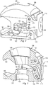
- Figs. 9-12 show a second embodiment of a clamping device, referenced herein by the numeral 300.
- This embodiment is similar in many respects to the embodiment described above, but includes a pin clamp 304 in combination with the rod clamp 102.
- the clamping device 300 is a part of a fixation system that may include a bone pin and a fixation rod.
- Other clamp embodiments are also contemplated, and the surgeon can build a structure to meet the needs of the particular case utilizing bar to bar clamps, bar to pin clamps, bars and bone pins.
- the pin clamp 304 includes an outer jaw 308 and an inner jaw 310 that are shaped to receive a bone pin, which typically includes a smaller diameter than a fixation rod. Accordingly, the outer and inner jaws 308, 310 differ in construct to accommodate the bone pin while maintaining all other aspects the same, including the block 112 and the link 114.
- the clamping device 300 operates in the same manner described above. That is, a surgeon may use the clamping assembly 300 as a part of an external fixation system to fix a rod to a bone pin or a rod to another rod. With the clamps 102, 304 in the open position shown in Figs. 9 and 10 , the surgeon may introduce the rods or pins into the openings formed between the inner and outer jaws. The surgeon may then manually actuate the block 112 of each respective clamp so that the respective clamp snaps onto or otherwise closes about the rod or pin, to capture the rod or pin. Actuating the block 112 may include pressing the tab 174 on the block 112 so that it pivots about the axles.
- the block 112 rotates, guided by the links 114 and axles 116, so that an interference portion of the block 112 advances between the rear portions of the inner and outer jaws.
- the rear portion of the outer jaw moves away from the rear portion of the inner jaw, creating a gap therebetween that is filled by the advancing block 112.
- the front ends of the jaws move toward each other in manner that captures the rod or pin therebetween.
- the rod or pin is captured between the inner and outer jaws.
- the captured rod or pin can be rotated within the jaws and the clamping assembly may be slid in the direction of the rod axis along the rod.
- the locking system 106 To rigidly lock the clamp on the rod or pin, the locking system 106 must be actuated as described above.
- opening the clamp occurs by using the tab 174 to pull the block 112 out from between the inner and outer clamps.
- the biasing member 124 here shown as a coil spring, biases the jaws open as soon as the block is removed sufficiently from the space between the backs of the jaws.
Landscapes
- Health & Medical Sciences (AREA)
- Orthopedic Medicine & Surgery (AREA)
- Life Sciences & Earth Sciences (AREA)
- Surgery (AREA)
- Biomedical Technology (AREA)
- Engineering & Computer Science (AREA)
- Nuclear Medicine, Radiotherapy & Molecular Imaging (AREA)
- Heart & Thoracic Surgery (AREA)
- Medical Informatics (AREA)
- Molecular Biology (AREA)
- Animal Behavior & Ethology (AREA)
- General Health & Medical Sciences (AREA)
- Public Health (AREA)
- Veterinary Medicine (AREA)
- Surgical Instruments (AREA)
Description
- This application is directed to a clamping system for an external fixation system.
- External fixation systems are used to stabilize fractured bones or secure bones after corrective surgery. They are usually made up of structural members held together by clamps, all assembled by the surgeon during surgery. The clamps are placed on bone pins and are attached to bars, creating a frame to hold the bones in particular relationships. Typically, the external fixation frame is assembled in the configuration the surgeon desires, then the fracture is reduced and the clamps are tightened. Some conventional clamps have to be tightened partially to provisionally lock the bone pin or bar into the clamp. Others require insertion of a fixation element against a spring force possibly making insertion more difficult than necessary.
- The present disclosure overcomes one or more of the deficiencies in the prior art.
-
US 4,388, 747 A discloses a clamp assembly for ducting or cabling, comprising a first jaw and a second jaw,
the first and second jaws together forming a passage for receiving the ducting or cabling,
a first link attached to the first jaw,
a second link attachted to the second jaw,
wherein the first and second links are pivotable between a first position and a second position, the first and second links being configured in a manner that the first and second jaws are open when the first and second links are disposed in the first position and are closed when the first and second links are in the second position, the links being configured to control the relative motion of the first and second jaws, the links being arranged such that, when the first and second jaws are closed, the first and second links resist separation of the jaws. - The present invention is directed to a clamp assembly as defined in claim 1. Preferred embodiments are defined in the dependent claims.
- Aspects of the present disclosure are best understood from the following detailed description when read with the accompanying figures.
-
Fig. 1 is an isometric view of a portion of an external fixation system showing one exemplary embodiment of a clamping assembly clamped onto fixation bars. -
Fig. 2 is a section view of the exemplary clamp assembly ofFig. 1 taken through lines 2-2, and showing only one of the fixation bars. -
Fig. 3 is an illustration of an exploded view of the exemplary clamp assembly ofFig. 1 . -
Fig. 4 is an illustration of a perspective view of a clamp of the exemplary clamping assembly ofFig. 1 . -
Fig. 5 is an illustration of a cross-sectional view of the clamp ofFig. 4 . -
Fig. 6 is an illustration of a perspective view of an inner jaw of the clamp ofFig. 4 . -
Fig. 7 is an illustration of a perspective view of an outer jaw of the clamp ofFig. 4 . -
Figs. 8A-8D are illustrations of cross-sectional views of the clamping assembly in different stages between open and closed according to one exemplary aspect of the present disclosure. -
Fig. 9 is an illustration of a side view of a second embodiment of an external fixation system with a clamp assembly having a pin clamp and a rod clamp according to one exemplary aspect of the present disclosure. -
Fig. 10 is a cross-sectional view through the clamping assembly ofFig. 9 showing the pin and rod clamps in the open condition without the fixation elements. -
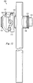
Fig. 11 is an isometric view of a portion of an external fixation system showing one exemplary embodiment of a clamp assembly clamped onto one bar and one bone pin. -
Fig. 12 is a side view of the portion of the external fixation system shown inFig. 11 , showing the exemplary clamp assembly clamped onto one bar and one bone pin. - It is to be understood that the following disclosure provides many different embodiments, or examples, for implementing different features of various embodiments. Specific examples of components and arrangements are described below to simplify the present disclosure. These are, of course, merely examples and are not intended to be limiting. In addition, the present disclosure may repeat reference numerals and/or letters in the various examples. This repetition is for the purpose of simplicity and clarity and does not in itself dictate a relationship between the various embodiments and/or configurations discussed.
- The external fixation system disclosed herein includes a clamping device having one or more clamps, arranged to receive and secure fixation rods or bars (or other fixation elements) and/or pins (or other fixation elements) that extend into and secure patient tissue. These clamps, however, may be arranged to open to a first condition wider than the width of the fixation element to be received, and configured to close or clamp onto the fixation element. A user can lock the clamp in the closed position by pressing a unique linking system that secures the fixation element within the clamp.
-
Fig. 1 shows an exemplary external fixation system 10 includingrigid bars clamping device 100. Although this disclosure references bars 12, 14 and later references pins, it should be understood that any fixation element may be used, including bone pins, wires, rings, struts, bars, rods, or other structural members. In the example inFig. 1 , eachbar clamping device 100 by inserting it between facing jaws of a clamp of theclamping device 100 as is described further below, to establish the external fixation framework for bone stabilization. Thebars clamping device 100 while the jaws maintain the fixation element in the clamp. Additional bar-to-bar fixation clamps and/or bar-to-pin fixation clamps may be added to expand and create an external fixation frame as required. Once properly created, the frame may be locked by changing the clamp from a provisionally locked condition to the fully locked condition. -
Figs. 2 and3 show additional details of an embodiment of theclamping device 100 according to one exemplary aspect of the present disclosure. Some like elements may be labeled with a suffix or separate reference number for clarity. - The
exemplary clamping device 100 includes aclamp 102, aclamp 104, and alocking assembly 106. Eachclamp clamping device 100 include a bar clamp and a pin clamp, while others include two pin clamps. Yet other embodiments include only a single clamp on one end, with a multi-clamp set or other arrangement on the other end. - Each
clamp clamping device 100 provides multiple degrees of freedom, including a roll axis and a yaw axis. The roll axis is the axis of a fixation element within one of the clamps and about which theclamping device 100 may rotate when the clamp is only provisionally locked. The yaw axis is defined by a stud (described below) and about which one of theclamps -
Figs. 2 and3 respectively show a cross-sectional view and an exploded view of theclamping device 100. Referring toFigs. 1-3 , theclamps outer jaw 108, aninner jaw 110, ablock 112, alink 114, and threeaxles 116a-116c. Thelocking assembly 106 includes a stud shown as abolt 118 and a locking member shown as anut 120. In addition to these elements of theclamps locking assembly 106, theclamping device 100 includes awasher 122 disposed adjacent eachouter jaw 108 and includes abiasing member 124 disposed between theinner jaws 110. - The
clamps fixation rod 12 inFig. 1 . These cooperate with theblock 112 and thelink 114 to apply loading that clamps the fixation element in a passage between the inner and outer jaws. -
Figs. 4 and 5 shows theclamp 102 in greater detail.Fig. 4 shows a perspective view andFig. 5 shows a cross-sectional view of theclamp 102.Fig. 6 shows another view of theinner jaw 110 separate from and independent of other elements of theclamp 102. - Referring to these Figures, the
inner jaw 110 cooperates with theouter jaw 108 to clamp onto and secure a fixation element. Theinner jaw 110 includes aninner clamp face 130 that faces toward theouter jaw 108 and includes an outer clamp face 132 (seeFig. 3 ) that faces and interfaces with the clamp 104 (Fig. 3 ). Acentral bore 133 extends from theinner clamp face 130 to theouter clamp face 132 and is sized to receive thebolt 118. Thecentral bore 133 includes a spring recess configured to receive the biasingmember 124. In addition, theinner jaw 110 includes atrack 134 and a connector portion shown as aboss 136 formed on each lateral side. Theboss 136 in this embodiment is formed as a half-cylinder projecting laterally from theinner jaw 110. Here, theboss 136 includes an axis formed by the cylindrical shape that is coincident with the plane of theinner clamp face 130. Thetrack 134 is formed between theboss 136 and acylindrical surface 138 concentric with the cylindrical surface of theboss 136. - The
inner clamp face 130 includes agripping surface portion 146 configured to interface with a fixation element such as arod 12 fromFig. 1 . In this example, thegripping surface portion 146 is a lateral recess. Although shown as smooth, the gripping surface portion may include a plurality of transverse teeth formed therein extending from one lateral side to the other that may interface or engage with a fixation element that is held between the inner andouter jaws gripping surface portion 154 may be formed with a rounded bottom portion, flats, faces, some other engaging surface, or some combination of these. - The
outer clamp face 132 includes aclamp interfacing portion 148 that selectively interfaces with the opposing clamp to restrict relative rotation when theclamping device 100 is in a fully locked condition. In one embodiment, theclamp interfacing portion 148 includes interdigitating portions. In some examples, these include poker-chip type surfaces, such as radially extending splines configured to interdigitate with the corresponding splines on the opposing clamp. In some examples, in place of the splines, theclamp interfacing portion 148 includes knurling, a roughened surface or other friction inducing features to enable theinner jaw 110 and the opposing interfacing surface of the opposing clamp to be selectively secured relative to each other. Some embodiments have smooth surfaces that frictionally engage under load to provide for and prevent selective relative rotation. - A
rear portion 139 of theinner jaw 110 includes aseat 140 shaped to receive thelink 114. Theseat 140 is formed in the rear surface and in theinner clamp face 130 of theinner jaw 110. As seen inFigs. 5 and6 , it includes a sloping surface and a curved basin at the bottom that matches the profile of thelink 114. Ablock seat 141 is disposed adjacent theseat 140 and is configured to receive ends of a portion of theblock 112 described below. - An
axle hole 142 passes through lateral sides of theinner jaw 110 and into theseat 140. One of theaxles 116c extends through thehole 142 and into thelink 114, pivotably connecting thelink 114 and theinner jaw 110. -
Fig. 7 shows theouter jaw 108 in greater detail. With reference toFig. 7 , and with reference toFigs. 4 and 5 , theouter jaw 108 includes acentral bore 148, aninner clamp face 150, and anouter clamp face 152. Theinner clamp face 150 includes a fixation element-receivinggripping surface portion 154 formed as a transverse groove and extending from one lateral side to another. It is shaped to cooperate with the inner jaw 126 to receive and secure a bar, pin or other fixation element in place between the inner and outer jaws. Like thegripping surface portion 146, thegripping surface portion 154 may be formed with a rounded bottom portion, flats, faces, some other engaging surface, or some combination of these. The gripping surfacedportion 146 and thegripping surface portion 154 form a passage therebetween for receiving and capturing a fixation element, such as a spinal rod, a bone pin, or other fixation element. - Connector portions extend from the
inner clamp face 150. These connector portions are arranged to interface with thebosses 136 on theinner jaw 110. In this example, the connector portions are J-shapedhooks 156 that extend into thetrack 134 and about thebosses 136. Thesehooks 156 enable theouter jaw 108 to pivot about thebosses 136 on theinner jaw 110, including about the center of the J-shaped hook. In this case, since thebosses 136 are semi-cylindrically shaped having an axis coincident with theinner clamp face 130, the pivot axis substantially corresponds to theinner clamp face 130. Thetracks 134 limit and guide the motion of thehooks 156, and the hook shape prevents undesired removal. In addition, the spacing of thetrack 134 and the length of thehook 156 maintain a desired spacing between the inner andouter jaws - The
outer jaw 108 also includeslateral recesses 158 toward arear portion 159 that receive and cooperate with theblock 112. Ahole 160 passes transversely through theouter jaw 108 and into the lateral recesses 158. Theaxle 116a may be received into thehole 160 and through theblock 112 to connect theblock 112 to theouter jaw 108. - The
outer clamp face 152 in this example is a smooth spherically-shaped surface that is configured to pivot or slide next to thewasher 122. In this example, thewasher 122 has a smooth spherical surface that nests with theouter clamp face 152. However, other shapes are contemplated. Thecentral bore 148 includes features that enable it to articulate relative to thebolt 118. As such, thecentral bore 148 is relatively oval shaped, with curved ends connected by parallel sides that allow theouter jaw 108 to displace within a plane relative to the bolt. - Returning to
Figs. 3 and4 , theblock 112 includes twoarm portions 164 connected by aback portion 166. As explained further below, thearm portions 164 are configured to cooperate with theinner jaw 110 and theouter jaw 108 to physically restrict or block the rear portions of the jaws from coming together, thereby restricting or blocking separation of the front ends of thejaws arm portions 164 each include afirst end 168 and asecond end 170 configured to respectively fit within or seat on theblock seat 141 on theinner jaw 110 and the lateral recesses 158 on theouter jaw 108. With thearm portions 164 within theirseats rear portions holes 172 extend through each of theends arm portions 164. The sets ofholes 172 in eacharm portion 164 align with each other, such that asingle axle 116 fits through each set ofholes 170, although separate axles or other arrangements may be employed. Theback portion 166 extends between and connects thearm portions 164. In this example, theback portion 166 includestabs 174 that longitudinally extend in the direction of thearm portions 164. Thesetabs 174 form a plate configured to be pressed by a user's finger or thumb to secure theclamp 102 on a fixation element. As shown inFig. 4 , first ends 168 of thearm portions 164 are received into the lateral recesses 158 formed in theouter jaw 108, and the second ends 170 of thearm portions 164 are received into the block seats 141 in theinner jaw 110. - Although the
block 112 may be disposed between thejaws rear portions rear portions link 114 from swinging towards the center of theclamp 102 prevents therear portion 159 of theouter jaw 108 from moving downward toward therear portion 139 of theinner jaw 110. For example, the load may instead go through the axles. Since theaxles 116 are relatively small pins, the recesses and the block seat inFigs. 5-7 allow the load to be carried by theblock 112 while reducing the chance of overstressing the axles. - The
link 114 is a solid block configured to fit between thearm portions 164 of theblock 112. Each end of thelink 114 includes ahole 176 for receiving one of theaxles 116. As can be seen inFig. 5 , thelink 114 is configured to be received within theseat 140. - In the example shown, the
inner jaw 110 is configured to receive theaxle 116c through thehole 142. Thelink 114 has twoholes 176, one of which also receives theaxle 116c. Theother hole 176 receives thesimilar axle 116b. Thisaxle 116b is also received in ahole 172 in theblock 112, pivotably connecting thelink 114 and theblock 112. The other end of thearm portion 164 of theblock 112 receives theaxle 116a, which is also received in thehole 160 in theouter jaw 108. - The
hook 156 of theouter jaw 108 bears against theinner jaw 110. Thishook 156 is also captured by theboss 136 of theinner jaw 110, preventing or limiting the distance that theouter jaw 108 can travel. When thetab 174 on theblock 112 is pressed in towards the middle of theclamp 102, theouter jaw 108 rotates around theboss 136, and theouter jaw 108 closes on a fixation element between thejaws hook 156 has a cross-sectional width smaller than a cross-sectional width of thetrack 134 so that thehook 156 can not only pivot about theboss 136, but thehook 156, and thus theouter jaw 108 as a whole, can also displace vertically relative to theinner jaw 110. As such, while the three axle pivot points are nearly fully constrained in this embodiment, the J-hook is sized to be smaller than thetrack 134 so theouter jaw 110 can lift up when the links are pushed over center (as described below with reference toFig. 8C ), and so the outer andinner jaws nut 120. - The section view in
Fig. 5 shows theholes 176 in thelink 114 for receiving theaxles hole 160 in theouter jaw 108, for receivingaxle 116a. - In the exemplary embodiment shown, the
clamp 102 includes four cooperating components that act as links of a linkage - theinner jaw 110, theouter jaw 108, thelink 114, and theblock 112. These together, pivoting about the threeaxles 116 and about the pivot connection formed at the hook and boss, help control the response to user manipulation of theblock 112, as manipulated by itsback portion 166 or itstab 174. - Returning to
Figs. 2 and3 , the biasingmember 124 biases the forward ends of the inner and outer jaws of eachclamp clamp jaws clamp clamp - When the
block 112 is pressed in towards the middle of theclamp 102, theouter jaw 108 moves to a provisionally locked position. In this position, the biasingelement 124 biases the inner andouter jaws clamp 102 in any direction besides the direction of the long axis of the fixation element, theinner jaw 110 andouter jaw 108 must move apart at their forward ends, where in this exemplary embodiment, they contact the fixation element. InFig. 2 , this can be seen with thejaws points jaws jaws block 112 is disposed between the inner andouter jaws Figs. 2 and4 . Additionally, force to remove the fixation element would apply loading that would separate thepoints 184, 186 (Fig. 2 ), thereby increasing the force on theblock 112. This is the case when just spring force of the biasingmember 124 biases the inner and outer jaws together. Additional clamping force applied by thelocking mechanism 106 formed of thenut 120 and bolt 118 squeezes the fixation element and theblock 112 even tighter, preventing a user from opening theclamp 102. Accordingly, the additional clamping force may change the provisionally locked condition, which may permit rotation and some manipulation of theclamp assembly 100 relative to the fixation elements, to a final or fully locked condition lock where theclamp assembly 100 is rigidly fixed in place relative to the fixation elements. - To open the
clamp systems 102 the clamping force from the lockingassembly 106 is relieved by loosening thenut 120. Once this is loosened enough to provide sufficient travel for theouter jaw 108, theblock 112 can be pulled away from the middle of theclamp 102 so that it is no longer between the inner andouter jaws outer jaw 108 will rotate to a fixation element receiving position. -
Figs. 8A-8D show the steps of locking a fixation element in theclamping device 100 in even greater detail. Although operation is the same between clamps, the description below references theclamp 104 rather than theclamp 102.Fig. 8A shows theclamping device 100 with theclamp 104 in an open position.Fig. 8B shows theclamping device 100 with theclamp 104 in the half-open position.Fig. 8C shows theclamping device 100 with the linkage of theclamp 104 in the top-center position.Fig. 8D shows theclamping device 100 with theclamp 104 in the closed, provisionally locked condition.Fig. 2 described above shows theclamping device 100 in the fully locked condition. - Referring first to
Fig. 8A , as can be seen and as described above, thelink 114 is connected to and pivots about theaxle 116a extending into theinner jaw 110, and theblock 112 is connected to and pivots about theaxle 116c extending into theouter jaw 108. Theaxle 116b pivotably connects theblock 112 and thelink 114. As described above, these four elements pivotably connect and form a linkage that can secure the fixation element within the clamp. To place theclamp 104 in position shown inFig. 8A , the surgeon pulls thetab 174 away from thejaws axles axles axles block 112 and theaxle link 114 increases, the distance between therear portions inner jaws Fig. 4 , theouter jaw 108 pivots relative to theinner jaw 110 at the connector portions, which in this example includeshooks 156 pivoting aboutbosses 136 on either side of theclamp 104. Thetrack 134 andcylindrical surface 138 prevent theouter jaw 108 from collapsing onto theinner jaw 110 and maintains the desired separation distance between thejaws outer jaw 108 pivots relative to theinner jaw 110 about the center of the J-hook. The biasingmember 124 biases theempty clamp 104 to the open position when thelink 114 and block 112 are in the position shown inFig. 8A . -
Fig. 8B shows the clamp in a half closed position, with the outer andinner jaws fixation element 12 on four sides. Accordingly, thefixation element 12 is fixed in place and does not move further into the passage formed between thejaws axles block 112 and theaxles link 114 decreases, bringing theaxles rear portions inner jaws fixation element 12. The biasingmember 124 continues to bias theclamp 104 to the open position when thelink 114 and block 112 are in the position shown inFig. 8B . However, since the change in angle forces the rearward end of thejaws member 124. Accordingly, at this point, the biasingelement 124 is still biasing the rearward portion of the inner jaws toward each other, thereby biasing the jaws toward an open position. -
Fig. 8C shows the linkage at the top center position with theaxles inner jaws block 112 and thelink 114. At this point, the biasingelement 124 is biasing theinner jaw 108 toward theouter jaw 110, thereby biasing the jaws toward each other to a closed, provisionally locked position. If the linkage moves from the neutral position to a position having a positive angle (away from the center of the clamp), the biasingelement 124 will bias the jaws toward an open position by pushing the rear portions together. In contrast, if the linkage moves from the neutral position to a position having a negative angle (toward the center of the clamp), the biasingelement 124 will bias the jaws toward a closed, provisionally locked position by pushing the linkage into the position shown inFig. 8D . -
Fig. 8D shows the linkage in its seated, stable position. In this position, the biasingmember 124 biases theinner jaw 110 toward theouter jaw 108 in a manner that any applied force to open the jaws would actually drive the linkage, and ultimately the clamp, tighter into the closed position. For example, if the surgeon were to attempt to remove thefixation element 12 from between the outer andinner jaws rear portions rear portions block 112. In this position, as can be seen inFig. 8D , thelink 112 is fully seated in theseat 140 in theinner jaw 110. Likewise, thearm portions 164 of theblock 112 are fully seated in theblock seat 141 and in the lateral recesses 158. Since the biasingelement 124 is biasing the jaws together inFig. 8D , the chance of inadvertent opening of the clamp is reduced or entirely prevented. - With the
clamping device 100 arranged as shown inFig. 8D , thefixation element 12 is provisionally locked within theclamp 104. Accordingly, the clamp may pivot or slide about the fixation element and theclamp 104 may be rotated relative to theclamp 102 about thebolt 118. -
Fig. 3 shows theclamping device 100 in a fully locked condition. The clamping device arrives at this condition when the surgeon tightens thelocking mechanism 106, which in this example includes tightening thenut 120 on thebolt 118. This drives theclamps element 124. When theclamps clamp interfacing portions 148 engage and may prevent relative rotation. For example, interdigitations formed on theinner jaws 110 may engage and prevent relative rotation. At the same time, tightening thelocking mechanism 106 further presses the outer andinner jaws fixation element 12 until the fixation element is secured against movement relative to theclamping device 100, rigidly locking theclamping device 100. In this position, theclamping device 100 is in a fully locked condition. -
Figs. 9-12 show a second embodiment of a clamping device, referenced herein by the numeral 300. This embodiment is similar in many respects to the embodiment described above, but includes apin clamp 304 in combination with therod clamp 102. In this example theclamping device 300 is a part of a fixation system that may include a bone pin and a fixation rod. Other clamp embodiments are also contemplated, and the surgeon can build a structure to meet the needs of the particular case utilizing bar to bar clamps, bar to pin clamps, bars and bone pins. In this example, thepin clamp 304 includes anouter jaw 308 and aninner jaw 310 that are shaped to receive a bone pin, which typically includes a smaller diameter than a fixation rod. Accordingly, the outer andinner jaws block 112 and thelink 114. - The
clamping device 300 operates in the same manner described above. That is, a surgeon may use the clampingassembly 300 as a part of an external fixation system to fix a rod to a bone pin or a rod to another rod. With theclamps Figs. 9 and10 , the surgeon may introduce the rods or pins into the openings formed between the inner and outer jaws. The surgeon may then manually actuate theblock 112 of each respective clamp so that the respective clamp snaps onto or otherwise closes about the rod or pin, to capture the rod or pin. Actuating theblock 112 may include pressing thetab 174 on theblock 112 so that it pivots about the axles. As thetab 174 is pressed, theblock 112 rotates, guided by thelinks 114 andaxles 116, so that an interference portion of theblock 112 advances between the rear portions of the inner and outer jaws. As it advances, the rear portion of the outer jaw moves away from the rear portion of the inner jaw, creating a gap therebetween that is filled by the advancingblock 112. As the inner and outer jaws move away from each other at the rear portion, the front ends of the jaws move toward each other in manner that captures the rod or pin therebetween. - In this condition, the rod or pin is captured between the inner and outer jaws. However, in this embodiment, the captured rod or pin can be rotated within the jaws and the clamping assembly may be slid in the direction of the rod axis along the rod. To rigidly lock the clamp on the rod or pin, the
locking system 106 must be actuated as described above. - As described above, opening the clamp occurs by using the
tab 174 to pull theblock 112 out from between the inner and outer clamps. The biasingmember 124, here shown as a coil spring, biases the jaws open as soon as the block is removed sufficiently from the space between the backs of the jaws. - The foregoing has outlined features of several embodiments. Those skilled in the art should appreciate that they may readily use the present disclosure as a basis for designing or modifying other processes and structures for carrying out the same purposes and/or achieving the same advantages of the embodiments introduced herein. Those skilled in the art should also realize that such equivalent constructions do not depart from the spirit and scope of the present disclosure, and that they may make various changes, substitutions and alterations herein without departing from the spirit and scope of the present disclosure,
- The scope of the present invention is defined by the appended claims.
Claims (11)
- A clamp assembly (100) for an external fixation system for stabilizing fractured bones or securing bones after corrective surgery, comprising:a first jaw (108);a second jaw (110) having an inner surface (130) facing the first jaw (108),the first and second jaws together forming a passage for receiving a first fixation element of the external fixation system;a first link (112) attached to the first jaw (108); anda second link (114) attached to the second jaw (110), the first and second links (112, 114) being:the clamp assembly (100) further comprising a biasing element (124) arranged so as to bias the clamp open when the first and second links (112,114) are disposed in the first position.pivotable between a first position and a second position,the first and second links (112, 114) being configured in a manner that the first and second jaws (108, 110) are open when the first and second links (112, 114) are disposed in the first position and are closed when the first and second links (112, 114) are in the second position, the links (112, 114) being configured to control the relative motion of the first and second jaws (108, 110),the links (112, 114) being arranged such that, when the first and second jaws are closed,the first and second links (112, 114) resist separation of the jaws;
- The clamp assembly (100) of claim 1, wherein the clamp is arranged so that the biasing element (124) biases the clamp closed when the first and second links (112, 114) are disposed in the second position.
- The clamp assembly (100) of claim 1, wherein the first and second links (112, 114) are directly attached via a pivot connection.
- The clamp assembly (100) of claim 1, wherein the first jaw (108) includes a first connector portion (156) and wherein the second jaw (110) includes a second connector portion (136, 138), the first and second jaws (108, 110) being connected at the first and second connector portions (156, 136, 138).
- The clamp assembly (100) of claim 4, wherein the first connector portion (156) pivots about the second connector portion (136).
- The clamp assembly (100) of claim 4, wherein the first connector portion is a J-hook (156) and the second connector portion is a boss (136), the J-hook extending about the boss.
- The clamp assembly (100) of claim 4, wherein the first connector portion (156) is sized relative to the second connector portion (136, 138) to allow a limited amount of travel of the first jaw (108) relative to the second jaw (110).
- The clamp assembly (100) of claim 1, wherein the first link (112) comprises first and second arm portions (164) and a back portion (166) connecting the first and second arm portions (164), the second link (114) being disposable between the first and second arm portions (164).
- The clamp assembly (100) of claim 1, wherein the first jaw (108) is connected to the first link (112) via a first axle (116a) and wherein the second jaw (110) is connected to the second link (114) via a second axle (116c) and wherein the first and second links (112, 114) are connected via a third axle (116b).
- The clamp assembly (100) of claim 1, wherein the first and second links (112, 114) are arranged to pivot from the first position forming a positive angle between the first and second links (112, 114) to the second position forming a negative angle between the first and second links (112, 114).
- The clamp assembly of claim 1, wherein the first jaw (108) comprises a first seat (159) and the second jaw (110) comprises a second seat (141), the first link (112) being disposable into both the first and the second seats when the first and second jaws (108, 110) are closed.
Applications Claiming Priority (2)
| Application Number | Priority Date | Filing Date | Title |
|---|---|---|---|
| US41024810P | 2010-11-04 | 2010-11-04 | |
| PCT/US2011/059303 WO2012061692A1 (en) | 2010-11-04 | 2011-11-04 | Clamping assembly with links |
Publications (2)
| Publication Number | Publication Date |
|---|---|
| EP2635210A1 EP2635210A1 (en) | 2013-09-11 |
| EP2635210B1 true EP2635210B1 (en) | 2017-03-29 |
Family
ID=45002139
Family Applications (1)
| Application Number | Title | Priority Date | Filing Date |
|---|---|---|---|
| EP11785539.5A Active EP2635210B1 (en) | 2010-11-04 | 2011-11-04 | Clamping assembly with links |
Country Status (3)
| Country | Link |
|---|---|
| US (2) | US8728078B2 (en) |
| EP (1) | EP2635210B1 (en) |
| WO (1) | WO2012061692A1 (en) |
Families Citing this family (17)
| Publication number | Priority date | Publication date | Assignee | Title |
|---|---|---|---|---|
| EP1920720B1 (en) * | 2006-10-13 | 2014-03-19 | Stryker Trauma SA | Prevention of re-use of a medical device |
| IT1396145B1 (en) * | 2009-11-05 | 2012-11-16 | Citieffe Srl | MULTI-PURPOSE EXTERNAL FIXER. |
| EP2635210B1 (en) | 2010-11-04 | 2017-03-29 | Zimmer, Inc. | Clamping assembly with links |
| US20130180200A1 (en) * | 2012-01-12 | 2013-07-18 | Peter W. Gavin | Adjustable Rebar Connector |
| US9155561B2 (en) | 2013-03-06 | 2015-10-13 | Stryker Trauma Sa | Mini-rail external fixator |
| US9463045B2 (en) | 2013-03-15 | 2016-10-11 | Biomet Manufacturing, Llc | Polyaxial pivot housing for external fixation system |
| DE102013103486B4 (en) * | 2013-04-08 | 2014-11-27 | Rattunde & Co Gmbh | Clamping system for 7-fold cutting |
| DE102013103587B3 (en) | 2013-04-10 | 2014-05-22 | Rattunde & Co Gmbh | twin tensioner |
| US9962188B2 (en) | 2013-10-29 | 2018-05-08 | Cardinal Health 247. Inc. | External fixation system and methods of use |
| WO2016035050A1 (en) * | 2014-09-04 | 2016-03-10 | Mikai S.P.A. | External fixing system for orthopaedic exoskeleton |
| US10531896B2 (en) | 2015-08-10 | 2020-01-14 | Stryker European Holdings I, Llc | Distraction tube with wire clamp |
| US10945765B2 (en) * | 2017-12-06 | 2021-03-16 | Austin Miller Trauma LLC | Fixation clamp with spacer |
| MX2021008734A (en) * | 2019-01-22 | 2021-10-01 | Core Arms Llc | Mounting system, devices, methods and uses thereof. |
| US11627991B2 (en) | 2019-10-03 | 2023-04-18 | DePuy Synthes Products, Inc. | Adjustable combination clamp assembly |
| US11737786B2 (en) | 2019-12-31 | 2023-08-29 | Orthopediatrics Corp. | Multiple track system for positioning of bone segments |
| CN113413205B (en) * | 2021-05-25 | 2022-03-18 | 温州医科大学附属第二医院(温州医科大学附属育英儿童医院) | Medical screw clamping device |
| IT202100022832A1 (en) * | 2021-09-03 | 2023-03-03 | Citieffe Srl | EXTERNAL FIXATOR DEVICE CLAMP |
Family Cites Families (92)
| Publication number | Priority date | Publication date | Assignee | Title |
|---|---|---|---|---|
| US1706215A (en) | 1926-01-26 | 1929-03-19 | American Safety Device Co | Adjustable coupling means |
| US2705603A (en) | 1953-06-09 | 1955-04-05 | John O Bitz | Antenna pole clamp |
| US3154331A (en) | 1960-04-25 | 1964-10-27 | Armin E Engelhardt | Shaft clamping devices |
| US3044512A (en) | 1960-05-31 | 1962-07-17 | Monogram Prec Ind Inc | Clamp |
| US3406987A (en) | 1965-04-26 | 1968-10-22 | Minnesota Mining & Mfg | Split-sleeve sheet metal pipe coupling |
| US3373465A (en) | 1966-03-24 | 1968-03-19 | Up Right Inc | Locking hook with arcuately slidable locking member |
| CH558890A (en) | 1973-06-26 | 1975-02-14 | Glatz Ag | DEVICE FOR ADJUSTABLE CONNECTION OF AT LEAST TWO CONSTRUCTION ELEMENTS, IN PARTICULAR FOR PIPES OR BARS. |
| US4037978A (en) | 1974-08-23 | 1977-07-26 | B.C. Investments Ltd. | Resilient swivel connector |
| US4115966A (en) | 1977-02-14 | 1978-09-26 | Delee Barry | Clamping device for display structures |
| DE2830096A1 (en) | 1978-07-08 | 1980-01-17 | Raymond A Fa | ELASTIC CLAMP FOR RODS WITH VARIABLE DIAMETERS |
| US4388747A (en) * | 1981-08-10 | 1983-06-21 | Plummer Walter A | One-piece molded toggle clamp |
| DE3244819A1 (en) | 1982-12-03 | 1984-06-07 | Ortopedia Gmbh, 2300 Kiel | DEVICE FOR EXTERNAL FIXING OF BONE FRAGMENTS |
| US4483334A (en) | 1983-04-11 | 1984-11-20 | Murray William M | External fixation device |
| US4895141A (en) | 1984-04-26 | 1990-01-23 | Harrington Arthritis Research Center | Unilateral external fixation device |
| US4653481A (en) | 1985-07-24 | 1987-03-31 | Howland Robert S | Advanced spine fixation system and method |
| US4620533A (en) | 1985-09-16 | 1986-11-04 | Pfizer Hospital Products Group Inc. | External bone fixation apparatus |
| USD295725S (en) | 1985-12-06 | 1988-05-17 | Nifco Inc. | Retainer clamp for elongated bodies or the like |
| DE3604325A1 (en) | 1986-02-12 | 1987-08-13 | Ulrich Kreusel | CROSS-CONNECTOR FOR TWO CROSSING PIPES |
| JPH0339605Y2 (en) | 1986-07-23 | 1991-08-21 | ||
| HU209061B (en) | 1989-03-14 | 1994-03-28 | Tatar | External fastener for medicating fractures of bone |
| GB9000191D0 (en) * | 1990-01-04 | 1990-03-07 | Legge Philip | Scaffold couplers |
| WO1992012683A1 (en) | 1991-01-15 | 1992-08-06 | Confida S.A.S. | Single-use locking fastener device and bone support device |
| US5827282A (en) | 1991-07-12 | 1998-10-27 | Orthofix S.R.1. | Clamping coupling |
| US5312405A (en) | 1992-07-06 | 1994-05-17 | Zimmer, Inc. | Spinal rod coupler |
| JPH0796833B2 (en) | 1992-09-25 | 1995-10-18 | 政太郎 佐藤 | Clamp bracket assembly for connecting pipes |
| US5860728A (en) | 1993-02-08 | 1999-01-19 | Mag Instrument, Inc. | Holder clamp assembly |
| IT1262781B (en) | 1993-03-15 | 1996-07-04 | Giovanni Faccioli | TOOL AND METHOD FOR THE EXTERNAL REDUCTION OF FRACTURES |
| CH690293A5 (en) | 1994-09-06 | 2000-07-14 | Jaquet Orthopedie | Joint for components of an external fixator. |
| US5683389A (en) | 1994-12-05 | 1997-11-04 | Smith & Nephew, Inc. | External fixator for distal radius fractures |
| US5976141A (en) | 1995-02-23 | 1999-11-02 | Synthes (U.S.A.) | Threaded insert for bone plate screw hole |
| DE29515007U1 (en) | 1995-09-19 | 1995-12-07 | Pennig Dietmar | Osteosynthesis tools |
| US5800548A (en) | 1996-03-05 | 1998-09-01 | Bruno Franck | Device for transverse spinal connection |
| WO1997035527A1 (en) | 1996-03-25 | 1997-10-02 | Synthes Ag Chur | Adjustable clamp for bone fixation element |
| US5746741A (en) | 1996-05-06 | 1998-05-05 | Tufts University | External fixator system |
| US5891144A (en) | 1996-05-10 | 1999-04-06 | Jaquet Orthopedie S.A. | External fixator |
| EP1016187B1 (en) | 1996-05-29 | 2003-09-24 | Abb Ab | Conductor for high-voltage windings and a rotating electric machine comprising a winding including the conductor |
| US5899627A (en) | 1996-09-12 | 1999-05-04 | Minnesota Scientific, Inc. | Clamp for retractor support |
| US5727899A (en) | 1996-09-13 | 1998-03-17 | Minnesota Scientific, Inc. | Fulcrum clamp |
| IT1293941B1 (en) | 1997-02-13 | 1999-03-11 | Orthofix Srl | ORTHOPEDIC TOOL PARTICULARLY FOR THE SURGICAL CORRECTION OF BONE DEFORMATIONS |
| US5897555A (en) | 1997-05-15 | 1999-04-27 | Wright Medical Technology, Inc. | External fixation system and method |
| US5941879A (en) | 1997-11-18 | 1999-08-24 | Electro-Biology, Inc. | Method and apparatus for external fixation of bones |
| EP0838196A3 (en) | 1997-11-30 | 1998-07-01 | Daniel Spitzer | Clamping connector for medical tools and apparatus |
| DE59813676D1 (en) | 1998-05-19 | 2006-09-14 | Synthes Ag | CONNECTING ELEMENT FOR MONOLATERAL EXTERNAL FIXATION SYSTEM FOR TRAUMATOLOGY AND ORTHOPEDICS |
| AU742282B2 (en) | 1998-05-19 | 2001-12-20 | Synthes Gmbh | Cheek for a one-sided external fixation system for traumatology and orthopedics |
| AUPP396598A0 (en) | 1998-06-09 | 1998-07-02 | Pine Ridge Holdings Pty Ltd | Single action clamp |
| FR2787697B1 (en) | 1998-12-29 | 2001-06-15 | France Etat | MONOLATERAL ORTHOPEDIC EXTERNAL FIXATION DEVICE FOR BONE FRACTURE IMMOBILIZATION |
| CH693164A5 (en) | 1998-12-29 | 2003-03-27 | Stryker Trauma Sa | A locating and locking. |
| IT1307909B1 (en) | 1999-01-21 | 2001-11-29 | Medicalplastic S R L | EXTERNAL FIXER FOR ORTHOPEDICS AND TRAUMATOLOGY. |
| US6442805B2 (en) | 1999-03-26 | 2002-09-03 | Joel W. Pfister | Attachment system for configured slots |
| US6277119B1 (en) | 1999-10-21 | 2001-08-21 | Electro-Biology, Inc. | External fixation system |
| US6613049B2 (en) | 2000-02-02 | 2003-09-02 | Robert A. Winquist | Adjustable bone stabilizing frame system |
| US6622980B2 (en) | 2000-03-28 | 2003-09-23 | Hill-Rom Services, Inc. | Socket and rail clamp apparatus |
| US6386786B1 (en) | 2000-04-07 | 2002-05-14 | Delaware Capital Formation, Inc. | Rotating clamp |
| US7320556B2 (en) | 2000-07-11 | 2008-01-22 | Dall Vagn-Erik | Gripping devices |
| GB2367695B (en) | 2000-09-27 | 2004-09-08 | Alan Dick & Company Ltd | Cable clamp |
| JP2004527327A (en) | 2001-05-23 | 2004-09-09 | ボス インストルメンツ、リミテッド | Traction clamp assembly |
| US6887197B2 (en) | 2001-10-05 | 2005-05-03 | Boss Instruments Ltd. | Side loading surgical retractor having offset cavity |
| US7261713B2 (en) | 2001-10-09 | 2007-08-28 | Synthes (Usa) | Adjustable fixator |
| US6716212B1 (en) | 2002-01-25 | 2004-04-06 | Tyrone Sam Pickens | Universal modular external fixation system |
| US7048735B2 (en) | 2002-02-04 | 2006-05-23 | Smith & Nephew | External fixation system |
| US7004943B2 (en) | 2002-02-04 | 2006-02-28 | Smith & Nephew, Inc. | Devices, systems, and methods for placing and positioning fixation elements in external fixation systems |
| FR2835734B1 (en) | 2002-02-11 | 2004-10-29 | Scient X | CONNECTION SYSTEM BETWEEN A SPINAL ROD AND A CROSS BAR |
| US6637082B1 (en) | 2002-09-27 | 2003-10-28 | Chun-Yuan Chang | Quick holder |
| CA2530721C (en) | 2003-06-26 | 2012-04-10 | Synthes (U.S.A.) | Clamp for external fixation |
| EP1522266A1 (en) | 2003-10-06 | 2005-04-13 | Stryker Trauma SA | External fixation elements |
| US7241071B2 (en) | 2004-03-08 | 2007-07-10 | Jiffy Clip, Inc. | Swiveling multi-clamp fastener |
| AU2004318297A1 (en) | 2004-04-19 | 2005-10-27 | Synthes Gmbh | Elastic element produced from radiolucent material for a medical device |
| CA2495357A1 (en) | 2004-06-10 | 2005-12-10 | Newtrax Technologies Inc. | Rf volumetric intrusion detection device, system and method |
| US7314331B1 (en) | 2004-08-11 | 2008-01-01 | Tibor Koros | Multi-position locking mechanisms for clamping assemblies |
| ES2326269T3 (en) | 2004-08-20 | 2009-10-06 | Stryker Trauma Sa | TIGHTENING ELEMENT AND GASKET ELEMENT. |
| ES2303038T3 (en) | 2004-11-30 | 2008-08-01 | Stryker Trauma Sa | INSERTION PIECE FOR A CLAMPING ELEMENT, CLAMPING ELEMENT WITH AN INSERTION PIECE OF THIS TYPE, AND ARTICULATED UNION FORMED IN THIS MODE. |
| US7562855B2 (en) | 2004-12-15 | 2009-07-21 | Blanking Systems, Inc. | Clamping mechanism for folder gluer machine |
| US7473223B2 (en) | 2005-02-07 | 2009-01-06 | Peter Edward Fetzer | Push-button activated grasper for surgical retractor |
| DE502005005095D1 (en) | 2005-02-09 | 2008-10-02 | Stryker Trauma Sa | Insert for a clamping element, clamping element with such an insert and articulated connection formed therefrom |
| US7575575B2 (en) | 2005-03-18 | 2009-08-18 | Ron Anthon Olsen | Adjustable splint for osteosynthesis with modular components |
| DE202005005444U1 (en) | 2005-04-01 | 2005-06-02 | Tantum Ag | Particularly stable bone fixing device, assembled of two central elements and two fixing rods holding devices |
| US20060271045A1 (en) | 2005-05-27 | 2006-11-30 | Depuy Spine, Inc. | Spinal cross-connector |
| US8523858B2 (en) | 2005-06-21 | 2013-09-03 | DePuy Synthes Products, LLC | Adjustable fixation clamp and method |
| US20070038217A1 (en) | 2005-08-09 | 2007-02-15 | Brown Daniel G | Orthopaedic fixation clamp and method |
| US7628799B2 (en) | 2005-08-23 | 2009-12-08 | Aesculap Ag & Co. Kg | Rod to rod connector |
| US7588537B2 (en) | 2005-09-07 | 2009-09-15 | West Coast Surgical, Llc. | Connector with safety latch for a surgical retractor |
| EP1820461B1 (en) | 2006-02-21 | 2009-08-05 | Stryker Trauma SA | Clamping and articulation element |
| US7708736B2 (en) | 2006-02-22 | 2010-05-04 | Extraortho, Inc. | Articulation apparatus for external fixation device |
| EP1920720B1 (en) | 2006-10-13 | 2014-03-19 | Stryker Trauma SA | Prevention of re-use of a medical device |
| US7744632B2 (en) | 2006-12-20 | 2010-06-29 | Aesculap Implant Systems, Inc. | Rod to rod connector |
| GB2451227A (en) | 2007-07-03 | 2009-01-28 | Martin Arthur Elloy | External fixator pin clamp |
| WO2009042836A1 (en) | 2007-09-27 | 2009-04-02 | Qfx Technologies, Incorporated | Method and clamping apparatus for external fixation and stabilization |
| EP2294994B1 (en) | 2009-09-11 | 2018-04-04 | Stryker European Holdings I, LLC | External fixation component |
| CN103260535B (en) | 2010-07-01 | 2016-08-03 | 捷迈有限公司 | Multi-lock fixed pattern external fixation clamp |
| US8734446B2 (en) | 2010-10-12 | 2014-05-27 | Zimmer, Inc. | External fixation surgical clamp with swivel |
| EP3388007A3 (en) | 2010-10-12 | 2019-02-20 | Zimmer, Inc. | Single lock external fixation clamp arrangement |
| EP2635210B1 (en) | 2010-11-04 | 2017-03-29 | Zimmer, Inc. | Clamping assembly with links |
-
2011
- 2011-11-04 EP EP11785539.5A patent/EP2635210B1/en active Active
- 2011-11-04 WO PCT/US2011/059303 patent/WO2012061692A1/en active Application Filing
- 2011-11-04 US US13/289,214 patent/US8728078B2/en active Active
-
2014
- 2014-03-28 US US14/228,809 patent/US9510859B2/en active Active
Non-Patent Citations (1)
| Title |
|---|
| None * |
Also Published As
| Publication number | Publication date |
|---|---|
| US9510859B2 (en) | 2016-12-06 |
| US8728078B2 (en) | 2014-05-20 |
| EP2635210A1 (en) | 2013-09-11 |
| US20120289959A1 (en) | 2012-11-15 |
| WO2012061692A1 (en) | 2012-05-10 |
| US20140214033A1 (en) | 2014-07-31 |
Similar Documents
| Publication | Publication Date | Title |
|---|---|---|
| EP2635210B1 (en) | Clamping assembly with links | |
| US9750535B2 (en) | Method and clamping apparatus for external fixation and stabilization | |
| US10485586B2 (en) | Multi-locking external fixation clamp | |
| EP2627273B1 (en) | External fixation surgical clamp with swivel | |
| US9532805B2 (en) | Single lock external fixation clamp arrangement and method | |
| US9149296B2 (en) | Cam driven jaw for external fixation clamps |
Legal Events
| Date | Code | Title | Description |
|---|---|---|---|
| PUAI | Public reference made under article 153(3) epc to a published international application that has entered the european phase |
Free format text: ORIGINAL CODE: 0009012 |
|
| 17P | Request for examination filed |
Effective date: 20130604 |
|
| AK | Designated contracting states |
Kind code of ref document: A1 Designated state(s): AL AT BE BG CH CY CZ DE DK EE ES FI FR GB GR HR HU IE IS IT LI LT LU LV MC MK MT NL NO PL PT RO RS SE SI SK SM TR |
|
| DAX | Request for extension of the european patent (deleted) | ||
| RAP1 | Party data changed (applicant data changed or rights of an application transferred) |
Owner name: ZIMMER, INC. |
|
| RAP1 | Party data changed (applicant data changed or rights of an application transferred) |
Owner name: ZIMMER, INC. |
|
| 17Q | First examination report despatched |
Effective date: 20151102 |
|
| GRAP | Despatch of communication of intention to grant a patent |
Free format text: ORIGINAL CODE: EPIDOSNIGR1 |
|
| INTG | Intention to grant announced |
Effective date: 20161006 |
|
| RIN1 | Information on inventor provided before grant (corrected) |
Inventor name: MILLER, STEPHEN T. |
|
| GRAS | Grant fee paid |
Free format text: ORIGINAL CODE: EPIDOSNIGR3 |
|
| GRAA | (expected) grant |
Free format text: ORIGINAL CODE: 0009210 |
|
| AK | Designated contracting states |
Kind code of ref document: B1 Designated state(s): AL AT BE BG CH CY CZ DE DK EE ES FI FR GB GR HR HU IE IS IT LI LT LU LV MC MK MT NL NO PL PT RO RS SE SI SK SM TR |
|
| REG | Reference to a national code |
Ref country code: GB Ref legal event code: FG4D |
|
| REG | Reference to a national code |
Ref country code: CH Ref legal event code: EP |
|
| REG | Reference to a national code |
Ref country code: CH Ref legal event code: NV Representative=s name: MICHELI AND CIE SA, CH |
|
| REG | Reference to a national code |
Ref country code: AT Ref legal event code: REF Ref document number: 879021 Country of ref document: AT Kind code of ref document: T Effective date: 20170415 |
|
| REG | Reference to a national code |
Ref country code: IE Ref legal event code: FG4D |
|
| REG | Reference to a national code |
Ref country code: DE Ref legal event code: R096 Ref document number: 602011036483 Country of ref document: DE |
|
| PG25 | Lapsed in a contracting state [announced via postgrant information from national office to epo] |
Ref country code: FI Free format text: LAPSE BECAUSE OF FAILURE TO SUBMIT A TRANSLATION OF THE DESCRIPTION OR TO PAY THE FEE WITHIN THE PRESCRIBED TIME-LIMIT Effective date: 20170329 Ref country code: HR Free format text: LAPSE BECAUSE OF FAILURE TO SUBMIT A TRANSLATION OF THE DESCRIPTION OR TO PAY THE FEE WITHIN THE PRESCRIBED TIME-LIMIT Effective date: 20170329 Ref country code: LT Free format text: LAPSE BECAUSE OF FAILURE TO SUBMIT A TRANSLATION OF THE DESCRIPTION OR TO PAY THE FEE WITHIN THE PRESCRIBED TIME-LIMIT Effective date: 20170329 Ref country code: NO Free format text: LAPSE BECAUSE OF FAILURE TO SUBMIT A TRANSLATION OF THE DESCRIPTION OR TO PAY THE FEE WITHIN THE PRESCRIBED TIME-LIMIT Effective date: 20170629 Ref country code: GR Free format text: LAPSE BECAUSE OF FAILURE TO SUBMIT A TRANSLATION OF THE DESCRIPTION OR TO PAY THE FEE WITHIN THE PRESCRIBED TIME-LIMIT Effective date: 20170630 |
|
| REG | Reference to a national code |
Ref country code: NL Ref legal event code: MP Effective date: 20170329 |
|
| REG | Reference to a national code |
Ref country code: AT Ref legal event code: MK05 Ref document number: 879021 Country of ref document: AT Kind code of ref document: T Effective date: 20170329 |
|
| PG25 | Lapsed in a contracting state [announced via postgrant information from national office to epo] |
Ref country code: RS Free format text: LAPSE BECAUSE OF FAILURE TO SUBMIT A TRANSLATION OF THE DESCRIPTION OR TO PAY THE FEE WITHIN THE PRESCRIBED TIME-LIMIT Effective date: 20170329 Ref country code: BG Free format text: LAPSE BECAUSE OF FAILURE TO SUBMIT A TRANSLATION OF THE DESCRIPTION OR TO PAY THE FEE WITHIN THE PRESCRIBED TIME-LIMIT Effective date: 20170629 Ref country code: LV Free format text: LAPSE BECAUSE OF FAILURE TO SUBMIT A TRANSLATION OF THE DESCRIPTION OR TO PAY THE FEE WITHIN THE PRESCRIBED TIME-LIMIT Effective date: 20170329 Ref country code: SE Free format text: LAPSE BECAUSE OF FAILURE TO SUBMIT A TRANSLATION OF THE DESCRIPTION OR TO PAY THE FEE WITHIN THE PRESCRIBED TIME-LIMIT Effective date: 20170329 |
|
| REG | Reference to a national code |
Ref country code: FR Ref legal event code: PLFP Year of fee payment: 7 |
|
| PG25 | Lapsed in a contracting state [announced via postgrant information from national office to epo] |
Ref country code: NL Free format text: LAPSE BECAUSE OF FAILURE TO SUBMIT A TRANSLATION OF THE DESCRIPTION OR TO PAY THE FEE WITHIN THE PRESCRIBED TIME-LIMIT Effective date: 20170329 |
|
| PG25 | Lapsed in a contracting state [announced via postgrant information from national office to epo] |
Ref country code: RO Free format text: LAPSE BECAUSE OF FAILURE TO SUBMIT A TRANSLATION OF THE DESCRIPTION OR TO PAY THE FEE WITHIN THE PRESCRIBED TIME-LIMIT Effective date: 20170329 Ref country code: CZ Free format text: LAPSE BECAUSE OF FAILURE TO SUBMIT A TRANSLATION OF THE DESCRIPTION OR TO PAY THE FEE WITHIN THE PRESCRIBED TIME-LIMIT Effective date: 20170329 Ref country code: AT Free format text: LAPSE BECAUSE OF FAILURE TO SUBMIT A TRANSLATION OF THE DESCRIPTION OR TO PAY THE FEE WITHIN THE PRESCRIBED TIME-LIMIT Effective date: 20170329 Ref country code: ES Free format text: LAPSE BECAUSE OF FAILURE TO SUBMIT A TRANSLATION OF THE DESCRIPTION OR TO PAY THE FEE WITHIN THE PRESCRIBED TIME-LIMIT Effective date: 20170329 Ref country code: SK Free format text: LAPSE BECAUSE OF FAILURE TO SUBMIT A TRANSLATION OF THE DESCRIPTION OR TO PAY THE FEE WITHIN THE PRESCRIBED TIME-LIMIT Effective date: 20170329 Ref country code: EE Free format text: LAPSE BECAUSE OF FAILURE TO SUBMIT A TRANSLATION OF THE DESCRIPTION OR TO PAY THE FEE WITHIN THE PRESCRIBED TIME-LIMIT Effective date: 20170329 |
|
| PG25 | Lapsed in a contracting state [announced via postgrant information from national office to epo] |
Ref country code: SM Free format text: LAPSE BECAUSE OF FAILURE TO SUBMIT A TRANSLATION OF THE DESCRIPTION OR TO PAY THE FEE WITHIN THE PRESCRIBED TIME-LIMIT Effective date: 20170329 Ref country code: PT Free format text: LAPSE BECAUSE OF FAILURE TO SUBMIT A TRANSLATION OF THE DESCRIPTION OR TO PAY THE FEE WITHIN THE PRESCRIBED TIME-LIMIT Effective date: 20170731 Ref country code: IS Free format text: LAPSE BECAUSE OF FAILURE TO SUBMIT A TRANSLATION OF THE DESCRIPTION OR TO PAY THE FEE WITHIN THE PRESCRIBED TIME-LIMIT Effective date: 20170729 Ref country code: PL Free format text: LAPSE BECAUSE OF FAILURE TO SUBMIT A TRANSLATION OF THE DESCRIPTION OR TO PAY THE FEE WITHIN THE PRESCRIBED TIME-LIMIT Effective date: 20170329 |
|
| REG | Reference to a national code |
Ref country code: DE Ref legal event code: R097 Ref document number: 602011036483 Country of ref document: DE |
|
| PG25 | Lapsed in a contracting state [announced via postgrant information from national office to epo] |
Ref country code: DK Free format text: LAPSE BECAUSE OF FAILURE TO SUBMIT A TRANSLATION OF THE DESCRIPTION OR TO PAY THE FEE WITHIN THE PRESCRIBED TIME-LIMIT Effective date: 20170329 |
|
| PLBE | No opposition filed within time limit |
Free format text: ORIGINAL CODE: 0009261 |
|
| STAA | Information on the status of an ep patent application or granted ep patent |
Free format text: STATUS: NO OPPOSITION FILED WITHIN TIME LIMIT |
|
| 26N | No opposition filed |
Effective date: 20180103 |
|
| PG25 | Lapsed in a contracting state [announced via postgrant information from national office to epo] |
Ref country code: SI Free format text: LAPSE BECAUSE OF FAILURE TO SUBMIT A TRANSLATION OF THE DESCRIPTION OR TO PAY THE FEE WITHIN THE PRESCRIBED TIME-LIMIT Effective date: 20170329 |
|
| PG25 | Lapsed in a contracting state [announced via postgrant information from national office to epo] |
Ref country code: MC Free format text: LAPSE BECAUSE OF FAILURE TO SUBMIT A TRANSLATION OF THE DESCRIPTION OR TO PAY THE FEE WITHIN THE PRESCRIBED TIME-LIMIT Effective date: 20170329 |
|
| PG25 | Lapsed in a contracting state [announced via postgrant information from national office to epo] |
Ref country code: LU Free format text: LAPSE BECAUSE OF NON-PAYMENT OF DUE FEES Effective date: 20171104 |
|
| REG | Reference to a national code |
Ref country code: BE Ref legal event code: MM Effective date: 20171130 |
|
| PG25 | Lapsed in a contracting state [announced via postgrant information from national office to epo] |
Ref country code: MT Free format text: LAPSE BECAUSE OF NON-PAYMENT OF DUE FEES Effective date: 20171104 |
|
| REG | Reference to a national code |
Ref country code: FR Ref legal event code: PLFP Year of fee payment: 8 |
|
| PG25 | Lapsed in a contracting state [announced via postgrant information from national office to epo] |
Ref country code: BE Free format text: LAPSE BECAUSE OF NON-PAYMENT OF DUE FEES Effective date: 20171130 |
|
| PG25 | Lapsed in a contracting state [announced via postgrant information from national office to epo] |
Ref country code: HU Free format text: LAPSE BECAUSE OF FAILURE TO SUBMIT A TRANSLATION OF THE DESCRIPTION OR TO PAY THE FEE WITHIN THE PRESCRIBED TIME-LIMIT; INVALID AB INITIO Effective date: 20111104 |
|
| PG25 | Lapsed in a contracting state [announced via postgrant information from national office to epo] |
Ref country code: CY Free format text: LAPSE BECAUSE OF NON-PAYMENT OF DUE FEES Effective date: 20170329 |
|
| PG25 | Lapsed in a contracting state [announced via postgrant information from national office to epo] |
Ref country code: MK Free format text: LAPSE BECAUSE OF FAILURE TO SUBMIT A TRANSLATION OF THE DESCRIPTION OR TO PAY THE FEE WITHIN THE PRESCRIBED TIME-LIMIT Effective date: 20170329 |
|
| PG25 | Lapsed in a contracting state [announced via postgrant information from national office to epo] |
Ref country code: TR Free format text: LAPSE BECAUSE OF FAILURE TO SUBMIT A TRANSLATION OF THE DESCRIPTION OR TO PAY THE FEE WITHIN THE PRESCRIBED TIME-LIMIT Effective date: 20170329 |
|
| PG25 | Lapsed in a contracting state [announced via postgrant information from national office to epo] |
Ref country code: AL Free format text: LAPSE BECAUSE OF FAILURE TO SUBMIT A TRANSLATION OF THE DESCRIPTION OR TO PAY THE FEE WITHIN THE PRESCRIBED TIME-LIMIT Effective date: 20170329 |
|
| REG | Reference to a national code |
Ref country code: DE Ref legal event code: R082 Ref document number: 602011036483 Country of ref document: DE Representative=s name: VENNER SHIPLEY GERMANY LLP, DE Ref country code: DE Ref legal event code: R082 Ref document number: 602011036483 Country of ref document: DE Representative=s name: VENNER SHIPLEY LLP, DE |
|
| P01 | Opt-out of the competence of the unified patent court (upc) registered |
Effective date: 20230525 |
|
| PGFP | Annual fee paid to national office [announced via postgrant information from national office to epo] |
Ref country code: GB Payment date: 20231010 Year of fee payment: 13 |
|
| PGFP | Annual fee paid to national office [announced via postgrant information from national office to epo] |
Ref country code: IT Payment date: 20231002 Year of fee payment: 13 Ref country code: IE Payment date: 20231009 Year of fee payment: 13 Ref country code: FR Payment date: 20231011 Year of fee payment: 13 Ref country code: DE Payment date: 20231010 Year of fee payment: 13 Ref country code: CH Payment date: 20231202 Year of fee payment: 13 |