EP2633595B1 - A protection relay for sensitive earth fault portection - Google Patents
A protection relay for sensitive earth fault portection Download PDFInfo
- Publication number
- EP2633595B1 EP2633595B1 EP11817484.6A EP11817484A EP2633595B1 EP 2633595 B1 EP2633595 B1 EP 2633595B1 EP 11817484 A EP11817484 A EP 11817484A EP 2633595 B1 EP2633595 B1 EP 2633595B1
- Authority
- EP
- European Patent Office
- Prior art keywords
- current
- protection relay
- self powered
- earth
- protection
- Prior art date
- Legal status (The legal status is an assumption and is not a legal conclusion. Google has not performed a legal analysis and makes no representation as to the accuracy of the status listed.)
- Active
Links
- 238000005259 measurement Methods 0.000 claims description 19
- 238000001514 detection method Methods 0.000 claims description 17
- 238000000034 method Methods 0.000 claims description 9
- 238000012545 processing Methods 0.000 claims description 9
- 230000001629 suppression Effects 0.000 claims description 8
- 238000000691 measurement method Methods 0.000 claims description 4
- 238000004364 calculation method Methods 0.000 claims description 2
- 238000011156 evaluation Methods 0.000 claims description 2
- 238000013461 design Methods 0.000 description 8
- 230000035945 sensitivity Effects 0.000 description 5
- 230000006870 function Effects 0.000 description 4
- 230000008569 process Effects 0.000 description 3
- 238000010586 diagram Methods 0.000 description 2
- 238000012986 modification Methods 0.000 description 2
- 230000004048 modification Effects 0.000 description 2
- 208000032366 Oversensing Diseases 0.000 description 1
- 230000003044 adaptive effect Effects 0.000 description 1
- 230000000903 blocking effect Effects 0.000 description 1
- 230000008859 change Effects 0.000 description 1
- 239000000284 extract Substances 0.000 description 1
- 230000006698 induction Effects 0.000 description 1
- 230000001939 inductive effect Effects 0.000 description 1
- 238000009434 installation Methods 0.000 description 1
- 238000002955 isolation Methods 0.000 description 1
- 238000005457 optimization Methods 0.000 description 1
- 238000013139 quantization Methods 0.000 description 1
- 239000007787 solid Substances 0.000 description 1
Images

Classifications
-
- H—ELECTRICITY
- H02—GENERATION; CONVERSION OR DISTRIBUTION OF ELECTRIC POWER
- H02H—EMERGENCY PROTECTIVE CIRCUIT ARRANGEMENTS
- H02H3/00—Emergency protective circuit arrangements for automatic disconnection directly responsive to an undesired change from normal electric working condition with or without subsequent reconnection ; integrated protection
- H02H3/16—Emergency protective circuit arrangements for automatic disconnection directly responsive to an undesired change from normal electric working condition with or without subsequent reconnection ; integrated protection responsive to fault current to earth, frame or mass
-
- H—ELECTRICITY
- H02—GENERATION; CONVERSION OR DISTRIBUTION OF ELECTRIC POWER
- H02H—EMERGENCY PROTECTIVE CIRCUIT ARRANGEMENTS
- H02H1/00—Details of emergency protective circuit arrangements
- H02H1/04—Arrangements for preventing response to transient abnormal conditions, e.g. to lightning or to short duration over voltage or oscillations; Damping the influence of dc component by short circuits in ac networks
- H02H1/043—Arrangements for preventing response to transient abnormal conditions, e.g. to lightning or to short duration over voltage or oscillations; Damping the influence of dc component by short circuits in ac networks to inrush currents
-
- H—ELECTRICITY
- H02—GENERATION; CONVERSION OR DISTRIBUTION OF ELECTRIC POWER
- H02H—EMERGENCY PROTECTIVE CIRCUIT ARRANGEMENTS
- H02H3/00—Emergency protective circuit arrangements for automatic disconnection directly responsive to an undesired change from normal electric working condition with or without subsequent reconnection ; integrated protection
- H02H3/16—Emergency protective circuit arrangements for automatic disconnection directly responsive to an undesired change from normal electric working condition with or without subsequent reconnection ; integrated protection responsive to fault current to earth, frame or mass
- H02H3/162—Emergency protective circuit arrangements for automatic disconnection directly responsive to an undesired change from normal electric working condition with or without subsequent reconnection ; integrated protection responsive to fault current to earth, frame or mass for ac systems
- H02H3/165—Emergency protective circuit arrangements for automatic disconnection directly responsive to an undesired change from normal electric working condition with or without subsequent reconnection ; integrated protection responsive to fault current to earth, frame or mass for ac systems for three-phase systems
-
- H—ELECTRICITY
- H02—GENERATION; CONVERSION OR DISTRIBUTION OF ELECTRIC POWER
- H02H—EMERGENCY PROTECTIVE CIRCUIT ARRANGEMENTS
- H02H1/00—Details of emergency protective circuit arrangements
- H02H1/06—Arrangements for supplying operative power
- H02H1/063—Arrangements for supplying operative power primary power being supplied by fault current
-
- H—ELECTRICITY
- H02—GENERATION; CONVERSION OR DISTRIBUTION OF ELECTRIC POWER
- H02H—EMERGENCY PROTECTIVE CIRCUIT ARRANGEMENTS
- H02H3/00—Emergency protective circuit arrangements for automatic disconnection directly responsive to an undesired change from normal electric working condition with or without subsequent reconnection ; integrated protection
- H02H3/08—Emergency protective circuit arrangements for automatic disconnection directly responsive to an undesired change from normal electric working condition with or without subsequent reconnection ; integrated protection responsive to excess current
- H02H3/10—Emergency protective circuit arrangements for automatic disconnection directly responsive to an undesired change from normal electric working condition with or without subsequent reconnection ; integrated protection responsive to excess current additionally responsive to some other abnormal electrical conditions
- H02H3/105—Emergency protective circuit arrangements for automatic disconnection directly responsive to an undesired change from normal electric working condition with or without subsequent reconnection ; integrated protection responsive to excess current additionally responsive to some other abnormal electrical conditions responsive to excess current and fault current to earth
Definitions
- the invention relates to the field of electrical power distribution.
- the invention specifically relates to design of protection feature in a self powered protection relay.
- a protection relay also referred as Intelligent Electronic Device (IED) is a microcontroller based intelligent electronic device with a basic function to protect electrical equipment by tripping a circuit breaker and interrupting a power line in case of over current or earth fault situations.
- the tripping signal on behalf of a trip coil or other actuator of the circuit breaker is generated by the protection relay typically when the measured current in the line exceeds a nominal or preset value for a predefined time period.
- a self-supplied relay may be preferably used.
- the self-supplied protection relay utilizes energy from the current sensing transformers to supply to the relay electronics circuit and the energy required to operate trip coils.
- Inrush is mainly observed during switching in the large inductive loads like transformer, induction motor.
- the protection personnel set the earth fault settings on higher side (or even double) so as to avoid any mal-operation because of inrush at load start up. They then reduce the settings to lower values once load is under normal operation condition. This is only possible where point load (a single load like a motor or transformer) is being protected. The same may not be possible when a feeder is being protected. There could be different loads being switched in and out of the feeder and hence there could be multiple possibilities of inrush presence.
- US 4,068,283 relates to a circuit breaker solid state trip unit incorporating trip indicating circuit.
- US 3,739,229 describes a sectionalizing switch control with an overcurrent sensing circuit and an inrush current restraint circuit actuated by means for sensing the presence of voltage at the sectionalizing switch. If a fault occurs which is not in the feeder line in which the sectionalizing switch is located, voltage will continue to be present at the sectionalizing switch if a branch line repeating circuit breaker opens or will be present upon reclosing of the main repeating circuit breaker. When this voltage is present at the sectionalizing switch following reclosing of the main circuit breaker, the voltage sensing means will actuate the inrush current restraint means so that the ground fault overcurrent sensing means will not operate to produce a signal to the sectionalizing switch counting means due to load inrush current.
- the restraint means will operate for a length of time determined by the time required for the inrush load current to subside. If the fault is a ground fault in the feeder line in which the sectionalizing switch is located and is not remote from the sectionalizing switch, the voltage sensing means will also sense voltage at the sectionalizing switch when the main repeating circuit breaker recloses. However, the greater current available due to a fault causes the overcurrent sensing means to operate in spite of the restraint means and produce an output signal to the sectionalizing switch counting means.
- the ground fault overcurrent sensing means will produce a sufficient number of signals to the counting means for the latter to actuate the sectionalizing switch opening means to thereby cause opening of the switch contacts and isolation of the feeder line. Since the energy available from a ground fault overcurrent is relatively low compared to the energy available from the system voltage or current at the sectionalizing switch during the fault, power for operating the sectionalizing switch control is obtained from system voltage or current.
- the typical values for I nominal (In) are 1A and 5A.
- the nominal current for illustration purpose for the relay described in the invention is taken as 1A.
- the range 0.1 In to 20 In for earth setting is usual with auxiliary powered relay.
- the self powered relays require minimum time and phase currents to get powered on. Also, the inrush detection requires some additional time. With all these constraints it is required that relay shall give trip within claimed minimum trip time if there is a genuine fault. Further, the design of the relay needs to account for good current detection sensitivity.
- the sensitivity here, refers the ability to sense the minimum of earth fault leakage currents. Better sensitivity helps to identify possible major fault earlier. Only high end or point load protection relays have inrush protection in built as a feature. So, implementation of inrush protection in case of self powered relay with sensitive earth fault protection makes it a unique feature.
- the invention presents an efficient self-powered three phase non-directional overcurrent and earth-fault protection IED.
- Said relay offers sensitive earth fault protection. This protection is being achieved in tandem with optimal power on trip time (switching to fault) and with integrated logic for inrush discrimination.
- a self powered protection relay for providing electrical protection in an electrical system.
- the self supplied protection relay is powered on by the line current, at least one phase line that it is measuring.
- the relay requires certain minimum current and time.
- the threshold limits are set high creating difficulty in providing sensitive earth fault detection.
- the self supplied protection relay is provided with a current processing module adapted to measure and evaluate line current to generate trip signal.
- the current processing module has an inrush current suppression to block earth fault detection during an inrush condition and thereby increase sensitivity of fault detection.
- the self powered protection relay is adapted to provide wide operating range of 0.1 times the nominal current to 20 times the nominal current for protection setting and offers Definite Minimum Time (DMT) and Inverse Definite Minimum Time (IDMT) characteristics curve settings.
- the relay is adapted to provide a selectable external and internal earth current measurement technique to provide earth fault protection.
- the relay performs harmonic analysis using Discrete Fourier Transform (DFT) techniques to automatically detect fundamental frequency and performs internal settings.
- the harmonic contents (for second harmonics) are also computed to use for computation of harmonics factor to detect inrush condition.
- the inrush condition detection is provided as a firmware solution in the relay.
- the relay utilizes previous stored calibration factors for correcting phase current and earth current measurements obtained from calibration procedure relating measured output value with the provided input in all the gain sections (gain sub ranges in automatic gain control module) provided in the relay.
- the inrush suppression logic used in the relay uses detection of the conditions such as a) current signal not being in a steady state condition; b) the value of current being more than approximately 10% of the current sensor nominal value; c) the value of current being below the preset fault threshold value; and d) the harmonic content in the current signal at the second harmonic as a ratio to the harmonic content at the fundamental frequency exceeds the preset harmonic ratio threshold, to detect inrush condition.
- the conditions such as a) current signal not being in a steady state condition; b) the value of current being more than approximately 10% of the current sensor nominal value; c) the value of current being below the preset fault threshold value; and d) the harmonic content in the current signal at the second harmonic as a ratio to the harmonic content at the fundamental frequency exceeds the preset harmonic ratio threshold, to detect inrush condition.
- the steady state condition is detected based on any of the following condition a) the value of current at the fundamental frequency falls approximately below 10% of the current sensor nominal value; and b) the value of current at the fundamental frequency falls approximately in the range of 95% to 105% of the value of current at the fundamental frequency in the previous period when measured for at least one period.
- the invention describes an efficient self-powered three phase non-directional overcurrent and earth-fault protection IED provided with various DMT and IDMT characteristics curves for configuration.
- the self powered relays derive their operating power from the very current transformers that are being used for the measurement. They do not use any auxiliary power to operate their electronics circuit. Therefore, self powered relays do require minimum current to get fully powered on. Higher the current above the minimum required current, lower will be the time required for relay to get powered on. Higher the current means more is the energy available to power the relay.
- the self powered relay provides both earth fault protection and also the inrush protection.
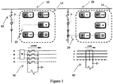
- the earth fault protection is provided in the manner depicted in Figure 1 .
- the relay 12 on detection of fault trips the circuit breaker 14. The following configurations are provided by the relay 12:
- the relay has two stage low-set and high-set non-directional overcurrent and earth-fault protection stages.
- the relay supports Definite time (DMT) and inverse DMT (IDMT) characteristics for both phase and earth-fault protection.
- DMT Definite time
- IDMT inverse DMT
- the operation of the low-set overcurrent stage I> and the low-set earth fault stage 10> is based on definite time or inverse time characteristics, as selected by the user.
- the high-set stage has instantaneous and definite time characteristics.
- the operating time of the stage will be a function of the current; the higher the current, the shorter the operating time.
- the stage includes seven time/current curve sets- four according to the BS 142 and IEC 60255 standards namely normal inverse, very inverse, extremely inverse and long time inverse and three special curves, name RI type curve, HR fuse curve and FR fuse curve.
- the relay offers sensitive earth fault protection with wide operating range of 0.1 I nominal to 20 I nominal , in both selectable external or internal vector summation earth current measuring techniques.
- the nominal value is 1 A in case of external earth and will be same as overcurrent stage in case of internal earth selection.
- Earth fault protection has both low-set and high-set stages with wide settings range.
- the low-set stage is also available with selectable DMT/IDMT characteristics where along with four standard IDMT characteristics (i.e.NI, EI, VI and LI) it also has special characteristics eg. RI, HR and FR, for better co-ordination within the electrical network.
- These protection stages are made adaptive to operating frequency of line inputs (range from 45Hz to 65Hz) by incorporating frequency estimation algorithm.
- a reliable protection is achieved by incorporating better design of earth CT and employing algorithm for curve fitting with calibration process of earth CT characteristics.
- the challenge with the CT design is the size against the required dynamic faithful measurement range 0.1A to 20A absolute at a given burden of 0.1VA. With respect to size to VA ratio, it is a difficult design. Precision is required with respect to CT performance at lower currents. All above this, sensitivity at lower points is further improved and false tripping avoided by inrush discrimination protection algorithm which utilizes fundamental and second harmonic component values measured by a DFT (Discrete Fourier Transform) algorithm. In case any inrush detection in phase, the earth protection gets blocked automatically. This helps in allowing system power on with sensitive earth fault protection settings.
- DFT Discrete Fourier Transform
- the relay has input terminals for interface to three phase line, 205 and earth line, 25 by using sensing CTs (not shown in this figure).
- the relay is a self powered relay that extracts power from the 3 phase line currents for getting into operation fully, dynamic control of current flow i.e. VBUS control is required and that is provided with controlled MOSFET Switching, 210 to power the relay without disturbing current measurement and effective charging the power supply for the relay from the current in the line (minimize time).
- the relay has a controller 240 to perform software computation and manage operation of the relay.
- the other modules relevant for calibration are zero cross over sensing module, 220 and harmonic analyzer (not shown in the figure) using DFT algorithm to provide automatic frequency detection and measurement of current signal.
- Current evaluation module 250 is also depicted in the figure as it represents the firmware used in the relay for operations involving processing of current signal for measurement and protection.
- the gain control module 230 using multiplexer (Mux) and various amplifiers along with the output module 260 are depicted in the figure and these modules help selection of appropriate gain for measurement and also operated in calibration procedure.
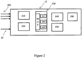
- the relay with its separate analog measurement channels for 3 phase and 1 earth currents provides phase and earth current measurement range (e.g. for earth current it is 0.1A to 20A absolute and for phase it is 75mA to 6.5A absolute on the secondary side of the external current transformer) and to provide for this range, for better measurement, the range has been divided in to 3 sections (depicted in the gain control module 230 in Figure 2 ) called the gain stages in the relay. Each gain stage helps to condition or scale given current section in to 0V to 3.3V. This is required for accurate current measurement.
- the relay is designed to have 3 gain stages called, Gain 1 Gain 8 and Gain 32
- Power on trip time is a term being used for any relay (auxiliary or self powered) when relays are being switched in to a faulty system.
- the time taken by relay to clear the fault when switched in (relay power "off to "on” condition and protection function time set to minimum possible by relay) to faulty system is called the "power on trip time”.
- the optimal power on trip time refers the minimum power on trip time for a given self powered relay. Design optimization is made to minimize the power on trip time by having efficient algorithm for measurement and protection and with a good balance between the hardware and firmware implementation of the features of the relay.
- the algorithm for detection of the steady-state condition is based on detection of the following condition:
- Protection IEC ANSI Three phase overcurrent protection, low-set stage 3I> 51 Three phase overcurrent protection, high-set stage 3I>> 50 / 51 Earth-fault protection, low-set stage I 0 > 51N Earth-fault protection, high-set stage I 0 >> 50N / 51N Three phase transformer inrush detector 3I 2f > 68
- the feature described in the invention though illustrated for self powered protection relay is also applicable for protection relay including self powered relay provided with auxiliary power source.
- the inrush suppression feature though illustrated for earth fault protection is also applicable for phase current fault or any other fault condition that requires inrush suppression for better performance.
Landscapes
- Engineering & Computer Science (AREA)
- Power Engineering (AREA)
- Emergency Protection Circuit Devices (AREA)
Description
- The invention relates to the field of electrical power distribution. The invention specifically relates to design of protection feature in a self powered protection relay.
- A protection relay, also referred as Intelligent Electronic Device (IED), is a microcontroller based intelligent electronic device with a basic function to protect electrical equipment by tripping a circuit breaker and interrupting a power line in case of over current or earth fault situations. The tripping signal on behalf of a trip coil or other actuator of the circuit breaker is generated by the protection relay typically when the measured current in the line exceeds a nominal or preset value for a predefined time period. In certain situations such as Ring Main Units (RMU) installations in urban areas, a self-supplied relay may be preferably used. The self-supplied protection relay utilizes energy from the current sensing transformers to supply to the relay electronics circuit and the energy required to operate trip coils. The design of self-supplied relay have several constrains associated with it to ensure the measurements are accurate and sensitive. Also, special provisions are required to make its circuitry efficient and optimized for power consumption. Some of these constraints and method to generate power supply by controlled charging are disclosed in the WIPO publication
WO 2009101463 . - Inrush is mainly observed during switching in the large inductive loads like transformer, induction motor. In field, usually, the protection personnel set the earth fault settings on higher side (or even double) so as to avoid any mal-operation because of inrush at load start up. They then reduce the settings to lower values once load is under normal operation condition. This is only possible where point load (a single load like a motor or transformer) is being protected. The same may not be possible when a feeder is being protected. There could be different loads being switched in and out of the feeder and hence there could be multiple possibilities of inrush presence.
US 4,068,283 relates to a circuit breaker solid state trip unit incorporating trip indicating circuit.US 3,739,229 describes a sectionalizing switch control with an overcurrent sensing circuit and an inrush current restraint circuit actuated by means for sensing the presence of voltage at the sectionalizing switch. If a fault occurs which is not in the feeder line in which the sectionalizing switch is located, voltage will continue to be present at the sectionalizing switch if a branch line repeating circuit breaker opens or will be present upon reclosing of the main repeating circuit breaker. When this voltage is present at the sectionalizing switch following reclosing of the main circuit breaker, the voltage sensing means will actuate the inrush current restraint means so that the ground fault overcurrent sensing means will not operate to produce a signal to the sectionalizing switch counting means due to load inrush current. The restraint means will operate for a length of time determined by the time required for the inrush load current to subside. If the fault is a ground fault in the feeder line in which the sectionalizing switch is located and is not remote from the sectionalizing switch, the voltage sensing means will also sense voltage at the sectionalizing switch when the main repeating circuit breaker recloses. However, the greater current available due to a fault causes the overcurrent sensing means to operate in spite of the restraint means and produce an output signal to the sectionalizing switch counting means. If the ground fault continues during a predetermined number of opening operations by the main repeating circuit breaker, the ground fault overcurrent sensing means will produce a sufficient number of signals to the counting means for the latter to actuate the sectionalizing switch opening means to thereby cause opening of the switch contacts and isolation of the feeder line. Since the energy available from a ground fault overcurrent is relatively low compared to the energy available from the system voltage or current at the sectionalizing switch during the fault, power for operating the sectionalizing switch control is obtained from system voltage or current. The typical values for I nominal (In) are 1A and 5A. The nominal current for illustration purpose for the relay described in the invention is taken as 1A. The range 0.1 In to 20 In for earth setting is usual with auxiliary powered relay. Even in such relays, it is difficult to set relays for 0.1 In earth setting in field if they are not having inrush blocking protection. At places where inrush is evident and if relays are not having inrush protection and if relay is set for lower earth fault settings (of the order of 0.1 In), the relay generates trip imagining an earth fault. This is however, not a true earth fault as an inrush is not a fault condition.
In such cases, it could be possible that sensitive (lower) earth fault settings like 0.1 In is not used. The same is applicable to phase protection also. As a result, there are relays with a feature of automatic setting double the value for a limited time to avoid mal operation because of inrush.
Further, achieving the functionality for self powered relay is complicated. The self powered relays require minimum time and phase currents to get powered on. Also, the inrush detection requires some additional time. With all these constraints it is required that relay shall give trip within claimed minimum trip time if there is a genuine fault.
Further, the design of the relay needs to account for good current detection sensitivity. The sensitivity, here, refers the ability to sense the minimum of earth fault leakage currents. Better sensitivity helps to identify possible major fault earlier.
Only high end or point load protection relays have inrush protection in built as a feature. So, implementation of inrush protection in case of self powered relay with sensitive earth fault protection makes it a unique feature.
The invention presents an efficient self-powered three phase non-directional overcurrent and earth-fault protection IED. - It is an objective of the invention to provide a self powered relay according to
claim 1. Said relay offers sensitive earth fault protection. This protection is being achieved in tandem with optimal power on trip time (switching to fault) and with integrated logic for inrush discrimination. - In an aspect of the invention, a self powered protection relay for providing electrical protection in an electrical system is provided. The self supplied protection relay is powered on by the line current, at least one phase line that it is measuring. To power on the self supplied relay and to have it fully operational, the relay requires certain minimum current and time. During the power ON condition for the relay (eg during reset of fault condition) or when there is a load change, inrush condition may result and in order to have the relay not generate trip signal to trip the line, usually the threshold limits are set high creating difficulty in providing sensitive earth fault detection. The self supplied protection relay is provided with a current processing module adapted to measure and evaluate line current to generate trip signal. The current processing module has an inrush current suppression to block earth fault detection during an inrush condition and thereby increase sensitivity of fault detection.
- In one embodiment, the self powered protection relay is adapted to provide wide operating range of 0.1 times the nominal current to 20 times the nominal current for protection setting and offers Definite Minimum Time (DMT) and Inverse Definite Minimum Time (IDMT) characteristics curve settings. In another embodiment, the relay is adapted to provide a selectable external and internal earth current measurement technique to provide earth fault protection.
- In another embodiment, the relay performs harmonic analysis using Discrete Fourier Transform (DFT) techniques to automatically detect fundamental frequency and performs internal settings. The harmonic contents (for second harmonics) are also computed to use for computation of harmonics factor to detect inrush condition. The inrush condition detection is provided as a firmware solution in the relay.
- In another embodiment, the relay utilizes previous stored calibration factors for correcting phase current and earth current measurements obtained from calibration procedure relating measured output value with the provided input in all the gain sections (gain sub ranges in automatic gain control module) provided in the relay.
- In yet another embodiment, the inrush suppression logic used in the relay is provided. The logic uses detection of the conditions such as a) current signal not being in a steady state condition; b) the value of current being more than approximately 10% of the current sensor nominal value; c) the value of current being below the preset fault threshold value; and d) the harmonic content in the current signal at the second harmonic as a ratio to the harmonic content at the fundamental frequency exceeds the preset harmonic ratio threshold, to detect inrush condition. \
- In the embodiment, the steady state condition is detected based on any of the following condition a) the value of current at the fundamental frequency falls approximately below 10% of the current sensor nominal value; and b) the value of current at the fundamental frequency falls approximately in the range of 95% to 105% of the value of current at the fundamental frequency in the previous period when measured for at least one period.
- Other features and advantages will become apparent to those skilled in the art upon reading the description of the preferred exemplary embodiments in conjunction with the accompanying drawings, wherein:
-
Figure 1 provides configurations for the protection relay as per an embodiment of the invention; -
Figure 2 provides a block diagram of components of the protection relay; -
Figure 3 provides an inrush suppression logic for earth current protection. - The invention describes an efficient self-powered three phase non-directional overcurrent and earth-fault protection IED provided with various DMT and IDMT characteristics curves for configuration.
- The self powered relays derive their operating power from the very current transformers that are being used for the measurement. They do not use any auxiliary power to operate their electronics circuit. Therefore, self powered relays do require minimum current to get fully powered on. Higher the current above the minimum required current, lower will be the time required for relay to get powered on. Higher the current means more is the energy available to power the relay.
- The self powered relay provides both earth fault protection and also the inrush protection. The earth fault protection is provided in the manner depicted in
Figure 1 . Therelay 12 on detection of fault trips thecircuit breaker 14. The following configurations are provided by the relay 12: - 1. Internal earth fault protection: In this
configuration 10, the relay, 12 measures the earth current by soft calculation, 15. It measures the 3 phase currents with the residualcurrent measurement arrangement 30 and their vector summation gives the earth current magnitude and phase. - 2. Earth fault protection through dedicated earth fault CT: In this
configuration 20, the relay, 12 has a connection, 25 for an external core balance CT (CBCT) used for earth fault detection with thearrangement 40. The CBCT magnetically senses the resultant of 3 phase currents that is nothing but the system earth current. This type of measurement may be preferred for more accurate and sensitive measurement. - The relay has two stage low-set and high-set non-directional overcurrent and earth-fault protection stages. The relay supports Definite time (DMT) and inverse DMT (IDMT) characteristics for both phase and earth-fault protection. The operation of the low-set overcurrent stage I> and the low-set
earth fault stage 10> is based on definite time or inverse time characteristics, as selected by the user. The high-set stage has instantaneous and definite time characteristics. - When IDMT characteristic has been selected, the operating time of the stage will be a function of the current; the higher the current, the shorter the operating time. The stage includes seven time/current curve sets- four according to the BS 142 and IEC 60255 standards namely normal inverse, very inverse, extremely inverse and long time inverse and three special curves, name RI type curve, HR fuse curve and FR fuse curve.
- The relay offers sensitive earth fault protection with wide operating range of 0.1 Inominal to 20 Inominal, in both selectable external or internal vector summation earth current measuring techniques. The nominal value is 1 A in case of external earth and will be same as overcurrent stage in case of internal earth selection. Earth fault protection has both low-set and high-set stages with wide settings range. The low-set stage is also available with selectable DMT/IDMT characteristics where along with four standard IDMT characteristics (i.e.NI, EI, VI and LI) it also has special characteristics eg. RI, HR and FR, for better co-ordination within the electrical network. These protection stages are made adaptive to operating frequency of line inputs (range from 45Hz to 65Hz) by incorporating frequency estimation algorithm.
- A reliable protection is achieved by incorporating better design of earth CT and employing algorithm for curve fitting with calibration process of earth CT characteristics. The challenge with the CT design is the size against the required dynamic faithful measurement range 0.1A to 20A absolute at a given burden of 0.1VA. With respect to size to VA ratio, it is a difficult design. Precision is required with respect to CT performance at lower currents. All above this, sensitivity at lower points is further improved and false tripping avoided by inrush discrimination protection algorithm which utilizes fundamental and second harmonic component values measured by a DFT (Discrete Fourier Transform) algorithm. In case any inrush detection in phase, the earth protection gets blocked automatically. This helps in allowing system power on with sensitive earth fault protection settings.
- The components relevant for calibration from the block diagram of the relay is illustrated in
Figure 2 . The relay has input terminals for interface to three phase line, 205 and earth line, 25 by using sensing CTs (not shown in this figure). As the relay is a self powered relay that extracts power from the 3 phase line currents for getting into operation fully, dynamic control of current flow i.e. VBUS control is required and that is provided with controlled MOSFET Switching, 210 to power the relay without disturbing current measurement and effective charging the power supply for the relay from the current in the line (minimize time). The relay has acontroller 240 to perform software computation and manage operation of the relay. The other modules relevant for calibration are zero cross over sensing module, 220 and harmonic analyzer (not shown in the figure) using DFT algorithm to provide automatic frequency detection and measurement of current signal.Current evaluation module 250 is also depicted in the figure as it represents the firmware used in the relay for operations involving processing of current signal for measurement and protection. Thegain control module 230 using multiplexer (Mux) and various amplifiers along with theoutput module 260 are depicted in the figure and these modules help selection of appropriate gain for measurement and also operated in calibration procedure. - The relay with its separate analog measurement channels for 3 phase and 1 earth currents provides phase and earth current measurement range (e.g. for earth current it is 0.1A to 20A absolute and for phase it is 75mA to 6.5A absolute on the secondary side of the external current transformer) and to provide for this range, for better measurement, the range has been divided in to 3 sections (depicted in the
gain control module 230 inFigure 2 ) called the gain stages in the relay. Each gain stage helps to condition or scale given current section in to 0V to 3.3V. This is required for accurate current measurement. - The relay is designed to have 3 gain stages called,
Gain 1
Gain 8 and
Gain 32 - Calibration is required to eliminate or minimize the measurement errors coming because of analog circuit components and quantization errors. Each of the gain forms a different analog circuit for a given analog channel. For example if we consider
phase 1, it has got 3 analog channel routs: one forgain 1, second for gain 8 and third for gain 32. It is therefore, important that relay gets calibrated for each of the phase and each of the gain. - So, in total there are 12 calibration constants identified during calibration process for 3 phases plus 1 external earth channel.
- In calibration process reference signal at 50 Hz for each line currents at different gain stages as an input are given to calibrate the system. For that it computes calibration factors & stores them in the nonvolatile memory (EEPROM) provided in the relay.
- Power on trip time is a term being used for any relay (auxiliary or self powered) when relays are being switched in to a faulty system. The time taken by relay to clear the fault when switched in (relay power "off to "on" condition and protection function time set to minimum possible by relay) to faulty system is called the "power on trip time". Here, the optimal power on trip time refers the minimum power on trip time for a given self powered relay. Design optimization is made to minimize the power on trip time by having efficient algorithm for measurement and protection and with a good balance between the hardware and firmware implementation of the features of the relay.
- The power on trip time is minimal, also with the inrush suppression feature to provide sensitive earth fault protection. As an exemplary illustration of the design of this feature, the logic for inrush detection is depicted in
Figure 3 and the algorithm is as follows: - If for at least one phase current, the logical combination of the following parameters may be considered:
- 1. Current is not in steady-state condition, (
steady state condition 330 is negated in the logic block 350)
AND - 2. Current value at fundamental frequency is above 10% of sensor nominal value(i.e. min. current threshold), 310
AND - 3. Current value is below the preset threshold (i.e. Fault current threshold), 320
AND - 4.
Harmonic ratio 340 between current values at 2nd harmonic 307 and that at thefundamental frequency 305 exceeds the preset threshold (i.e. Harmonic ratio threshold), - The algorithm for detection of the steady-state condition is based on detection of the following condition:
- 1. Current value at fundamental frequency falls below 10% of sensor nominal value OR
- 2. Current value at fundamental frequency is between 95% and 105% of the previous period for at least one period.
- The symbols/reference numbers used in the inventions are:
Protection IEC ANSI Three phase overcurrent protection, low-set stage 3I> 51 Three phase overcurrent protection, high-set stage 3I>> 50 / 51 Earth-fault protection, low-set stage I0> 51N Earth-fault protection, high-set stage I0>> 50N / 51N Three phase transformer inrush detector 3I2f> 68 - The feature described in the invention though illustrated for self powered protection relay is also applicable for protection relay including self powered relay provided with auxiliary power source. The inrush suppression feature though illustrated for earth fault protection is also applicable for phase current fault or any other fault condition that requires inrush suppression for better performance.
- While only certain features of the invention have been illustrated and described herein, many modifications and changes will occur to those skilled in the art. It is, therefore, to be understood that the appended claims are intended to cover all such modifications.
Claims (9)
- A self powered protection relay (12) for providing electrical protection in an electrical system, the electrical protection provided by measurement of current in at least one phase line in a medium voltage power line and generation of a trip signal on detection of overcurrent and earth fault condition in the medium voltage power line to operate a circuit breaker (14) for electrical protection comprising:a power supply module adapted to power the self powered protection relay from the at least one phase line that the self-powered relay is measuring to offer electrical protection in the electrical system; anda current processing module adapted to measure and evaluate current in the at least one phase line to generate the trip signal;wherein the current processing module is adapted to provide inrush current suppression to block detection of earth fault condition during an inrush condition; characterized in thatthe self powered protection relay (12) is adapted to providea selectable external (20) and internal (10) earth current measurement technique to provide earth fault protection, wherein the earth current is measured by soft calculation (15) in the internal (10) earth current measurement technique, and wherein the external (20) earth current measurement technique employs a connection (25) for an external core balance current transformer CT for sensing a system earth current.
- The self powered protection relay according to claim 1, characterized in that the self-powered protection relay (12) provides a provision for low threshold value setting for earth fault protection of approximately 0.1 times the nominal current rating of the self powered protection relay (12).
- The self powered protection relay according to claim 1, characterized in that the self powered protection relay (12) is adapted to provide fault protection in approximately the operating range of 0.1 times the nominal current rating of the self powered protection relay (12) to 20 times the nominal current rating of the self powered protection relay (12).
- The self powered protection relay according to claim 1, further comprises a selectable Definite Minimum Time (DMT) and Inverse Definite Minimum Time (IDMT) characteristics for protection.
- The self powered protection relay according to claim 1, characterized in that the current processing module automatically detects a medium voltage power line fundamental frequency from evaluation of current in the at least one phase line.
- The self powered protection relay according to claim 1, characterized in that the inrush condition detection is provided as a firmware in the self powered protection relay (12).
- The self powered protection relay according to claim 1, characterized in that the current processing module provides accurate measurement of current in the at least one phase line with the help of stored calibration factors obtained from calibration procedures to relate measured values with signals at an input for phase and external earth channels in the self powered protection relay.
- The self powered protection relay according to claim 1, characterized in that the current processing module determines inrush condition in the at least one phase line based on one or more states of a) current signal not being in a steady state condition; b) the value of current being more than approximately 10% of the current sensor nominal value; c) the value of current being below the preset fault threshold value (320); and d) the harmonic content in the current signal at the second harmonic (307) as a ratio (340) to the harmonic content at the fundamental frequency (305) exceeds a preset harmonic ratio threshold.
- The self powered protection relay according to claim 8, characterized in that the current processing module determines the state condition as steady based on one or more states of a) the value of current at the fundamental frequency falls approximately below 10% of the current sensor nominal value; and b) the value of current at the fundamental frequency (305) falls approximately in the range of 95% to 105% of the value of current at the fundamental frequency (305) in the previous period when measured for at least one period of the current signal.
Applications Claiming Priority (2)
| Application Number | Priority Date | Filing Date | Title |
|---|---|---|---|
| IN3213CH2010 | 2010-10-28 | ||
| PCT/IB2011/002524 WO2012056287A2 (en) | 2010-10-28 | 2011-10-21 | A protection relay for sensitive earth fault prtection |
Publications (2)
| Publication Number | Publication Date |
|---|---|
| EP2633595A2 EP2633595A2 (en) | 2013-09-04 |
| EP2633595B1 true EP2633595B1 (en) | 2017-12-13 |
Family
ID=45592750
Family Applications (1)
| Application Number | Title | Priority Date | Filing Date |
|---|---|---|---|
| EP11817484.6A Active EP2633595B1 (en) | 2010-10-28 | 2011-10-21 | A protection relay for sensitive earth fault portection |
Country Status (5)
| Country | Link |
|---|---|
| US (1) | US9343895B2 (en) |
| EP (1) | EP2633595B1 (en) |
| CN (1) | CN103354967B (en) |
| BR (1) | BR112013010580A8 (en) |
| WO (1) | WO2012056287A2 (en) |
Cited By (1)
| Publication number | Priority date | Publication date | Assignee | Title |
|---|---|---|---|---|
| US10804045B2 (en) | 2014-11-26 | 2020-10-13 | Siemens Aktiengesellschaft | Configurable circuit-breaker |
Families Citing this family (9)
| Publication number | Priority date | Publication date | Assignee | Title |
|---|---|---|---|---|
| US9046560B2 (en) * | 2012-06-04 | 2015-06-02 | Eaton Corporation | System and method for high resistance ground fault detection and protection in power distribution systems |
| CN105144526B (en) * | 2012-12-04 | 2018-03-30 | Abb研究有限公司 | The confession protective relay of module with improving performance |
| ES2903115T3 (en) * | 2013-06-10 | 2022-03-31 | Abb Schweiz Ag | Method and means for protection against complex and universal earth faults in high and medium voltage power systems |
| GB2539863A (en) * | 2013-09-19 | 2017-01-04 | Graham Chadwick David | Active current protection and monitoring device (ACPMD) |
| US9543886B2 (en) * | 2014-06-06 | 2017-01-10 | Actron Technology Corporation | Short circuit detection circuit and short circuit detection method for multi-phase rectifier at frequency domain |
| EP2955835B1 (en) * | 2014-06-12 | 2018-03-07 | Actron Technology Corporation | Short circuit detection circuit and short circuit detection method for multi-phase rectifier at frequency domain |
| US11342738B2 (en) | 2018-09-28 | 2022-05-24 | Florida Power & Light Company | Power generator protection system with arc flash incident energy reduction |
| US11031767B2 (en) | 2018-09-28 | 2021-06-08 | Florida Power & Light Company | Power relay system with arc flash incident energy reduction |
| TWI773479B (en) * | 2021-08-10 | 2022-08-01 | 上銀科技股份有限公司 | Relay safety system and robot arm controller |
Citations (1)
| Publication number | Priority date | Publication date | Assignee | Title |
|---|---|---|---|---|
| US3739229A (en) * | 1971-09-20 | 1973-06-12 | Mc Graw Edison Co | Overcurrent sensing and restraint control for sectionalizing switch |
Family Cites Families (11)
| Publication number | Priority date | Publication date | Assignee | Title |
|---|---|---|---|---|
| US4068283A (en) * | 1976-10-01 | 1978-01-10 | General Electric Company | Circuit breaker solid state trip unit incorporating trip indicating circuit |
| JPS57500313A (en) * | 1980-02-23 | 1982-02-18 | ||
| DE3114213C3 (en) * | 1980-04-15 | 1994-09-01 | Westinghouse Electric Corp | Method of operating a circuit breaker |
| US4402028A (en) * | 1981-08-17 | 1983-08-30 | Electric Power Research Institute, Inc. | Protective relay methods and apparatus |
| US6653899B2 (en) * | 2000-06-16 | 2003-11-25 | Niles Audio Corporation | Audio amplifier power and temperature controller having network detecting and associated methods |
| US6671144B1 (en) * | 2000-06-26 | 2003-12-30 | Premier Aviation, Inc. | Method and apparatus for detecting ground faults and for isolating power supply from the ground faults |
| GB2388482B (en) * | 2002-05-07 | 2005-06-15 | Alstom | Improved power line protection |
| CN2717084Y (en) * | 2004-05-20 | 2005-08-10 | 江苏东源电器集团股份有限公司 | Intelligent control and protection arrangement for high voltage vacuum circuit breaker |
| US20090154046A1 (en) * | 2007-12-18 | 2009-06-18 | Robinson Judy A | Trip unit and electrical switching apparatus including a movable indicator to indicate selection of an arc reduction maintenance system current condition |
| WO2009101463A1 (en) * | 2008-02-15 | 2009-08-20 | Abb Technology Ag | A standalone self-supplied numeric controlled relay |
| US8384292B2 (en) * | 2010-04-02 | 2013-02-26 | Osram Sylvania Inc. | Inrush current protection |
-
2011
- 2011-10-21 CN CN201180063289.6A patent/CN103354967B/en active Active
- 2011-10-21 EP EP11817484.6A patent/EP2633595B1/en active Active
- 2011-10-21 WO PCT/IB2011/002524 patent/WO2012056287A2/en active Application Filing
- 2011-10-21 BR BR112013010580A patent/BR112013010580A8/en not_active Application Discontinuation
-
2013
- 2013-04-29 US US13/872,554 patent/US9343895B2/en active Active
Patent Citations (1)
| Publication number | Priority date | Publication date | Assignee | Title |
|---|---|---|---|---|
| US3739229A (en) * | 1971-09-20 | 1973-06-12 | Mc Graw Edison Co | Overcurrent sensing and restraint control for sectionalizing switch |
Cited By (2)
| Publication number | Priority date | Publication date | Assignee | Title |
|---|---|---|---|---|
| US10804045B2 (en) | 2014-11-26 | 2020-10-13 | Siemens Aktiengesellschaft | Configurable circuit-breaker |
| DE102014224173B4 (en) | 2014-11-26 | 2023-08-10 | Siemens Aktiengesellschaft | circuit breaker |
Also Published As
| Publication number | Publication date |
|---|---|
| BR112013010580A8 (en) | 2017-12-19 |
| US9343895B2 (en) | 2016-05-17 |
| CN103354967A (en) | 2013-10-16 |
| WO2012056287A3 (en) | 2012-08-02 |
| EP2633595A2 (en) | 2013-09-04 |
| WO2012056287A2 (en) | 2012-05-03 |
| CN103354967B (en) | 2016-05-11 |
| BR112013010580A2 (en) | 2016-08-09 |
| US20130242441A1 (en) | 2013-09-19 |
Similar Documents
| Publication | Publication Date | Title |
|---|---|---|
| EP2633595B1 (en) | A protection relay for sensitive earth fault portection | |
| US8593133B2 (en) | Current measuring systems and methods of assembling the same | |
| AU2013401941B2 (en) | Distributed arc fault protection between outlet and circuit breaker | |
| KR101454203B1 (en) | Low current arc detecting system | |
| US7570465B2 (en) | Industrial arc fault circuit interrupter and method of detecting arcing conditions | |
| US8542021B2 (en) | Multi-pole arcing fault circuit breaker including a neutral current sensor | |
| US9178350B2 (en) | Electric distribution system protection | |
| KR101759598B1 (en) | Digital relay with sensibility of secondary circuit opening | |
| US20100149700A1 (en) | Power distribution system and electrical switching apparatus employing a filter trap circuit to provide arc fault trip coordination | |
| US11218023B2 (en) | Recloser control fast open circuit detection | |
| WO2016109690A1 (en) | Circuit breaker with current monitoring | |
| RU2550751C2 (en) | Method and device for detection of ground short-circuit | |
| JP6509029B2 (en) | Distribution board | |
| US11411390B2 (en) | Secure and dependable restricted earth fault protection for electric power generators and transformers | |
| AU2019447727B2 (en) | Electric line (L) protection device for detecting a leakage fault, a short-circuit, fault, an overcurrent fault and an arc fault | |
| Fidigatti et al. | Effect of harmonic pollution on low voltage overcurrent protection | |
| Blánquez et al. | Consideration of multi-phase criterion in the differential protection algorithm for high-impedance grounded synchronous generators | |
| KR20130114496A (en) | Over current ground relay and operating method thereof | |
| US7724488B2 (en) | Method for controlling an electronic overcurrent trip for low-voltage circuit breakers | |
| ITMI20011327A1 (en) | DIFFERENTIAL SWITCH FOR PROTECTION AGAINST EARTH LEAKAGE CURRENTS | |
| JP5656291B2 (en) | Shut-off device | |
| CN112753147B (en) | Low-voltage circuit breaker and fault arc identification unit | |
| Finney et al. | Ground fault protection for mv bus connected generators | |
| Yuvraj et al. | A MICROCONTROLLER BASED CONFIGURABLE PROTECTION RELAY TO PROTECT THE EQUIPMENTS AGAINST SINGLE PHASE AC-LINE FAULTS |
Legal Events
| Date | Code | Title | Description |
|---|---|---|---|
| PUAI | Public reference made under article 153(3) epc to a published international application that has entered the european phase |
Free format text: ORIGINAL CODE: 0009012 |
|
| 17P | Request for examination filed |
Effective date: 20130521 |
|
| AK | Designated contracting states |
Kind code of ref document: A2 Designated state(s): AL AT BE BG CH CY CZ DE DK EE ES FI FR GB GR HR HU IE IS IT LI LT LU LV MC MK MT NL NO PL PT RO RS SE SI SK SM TR |
|
| DAX | Request for extension of the european patent (deleted) | ||
| 17Q | First examination report despatched |
Effective date: 20150907 |
|
| GRAP | Despatch of communication of intention to grant a patent |
Free format text: ORIGINAL CODE: EPIDOSNIGR1 |
|
| RIC1 | Information provided on ipc code assigned before grant |
Ipc: H02H 1/06 20060101ALI20170508BHEP Ipc: H02H 3/10 20060101ALI20170508BHEP Ipc: H02H 3/16 20060101ALI20170508BHEP Ipc: H01H 83/00 20060101ALI20170508BHEP Ipc: H02H 1/04 20060101AFI20170508BHEP Ipc: H01H 71/12 20060101ALI20170508BHEP |
|
| INTG | Intention to grant announced |
Effective date: 20170602 |
|
| RIN1 | Information on inventor provided before grant (corrected) |
Inventor name: DESAI, PRIYANK Inventor name: SUTHAR, NIRAJ Inventor name: SHAH, VISHAL H. Inventor name: SHAFI, MOHAMMED, Y. |
|
| RAP1 | Party data changed (applicant data changed or rights of an application transferred) |
Owner name: ABB SCHWEIZ AG |
|
| GRAJ | Information related to disapproval of communication of intention to grant by the applicant or resumption of examination proceedings by the epo deleted |
Free format text: ORIGINAL CODE: EPIDOSDIGR1 |
|
| GRAR | Information related to intention to grant a patent recorded |
Free format text: ORIGINAL CODE: EPIDOSNIGR71 |
|
| GRAS | Grant fee paid |
Free format text: ORIGINAL CODE: EPIDOSNIGR3 |
|
| GRAA | (expected) grant |
Free format text: ORIGINAL CODE: 0009210 |
|
| INTC | Intention to grant announced (deleted) | ||
| INTG | Intention to grant announced |
Effective date: 20171030 |
|
| AK | Designated contracting states |
Kind code of ref document: B1 Designated state(s): AL AT BE BG CH CY CZ DE DK EE ES FI FR GB GR HR HU IE IS IT LI LT LU LV MC MK MT NL NO PL PT RO RS SE SI SK SM TR |
|
| REG | Reference to a national code |
Ref country code: GB Ref legal event code: FG4D |
|
| REG | Reference to a national code |
Ref country code: AT Ref legal event code: REF Ref document number: 955229 Country of ref document: AT Kind code of ref document: T Effective date: 20171215 Ref country code: CH Ref legal event code: EP |
|
| REG | Reference to a national code |
Ref country code: IE Ref legal event code: FG4D |
|
| REG | Reference to a national code |
Ref country code: DE Ref legal event code: R096 Ref document number: 602011044223 Country of ref document: DE |
|
| REG | Reference to a national code |
Ref country code: NL Ref legal event code: MP Effective date: 20171213 |
|
| REG | Reference to a national code |
Ref country code: LT Ref legal event code: MG4D |
|
| PG25 | Lapsed in a contracting state [announced via postgrant information from national office to epo] |
Ref country code: NO Free format text: LAPSE BECAUSE OF FAILURE TO SUBMIT A TRANSLATION OF THE DESCRIPTION OR TO PAY THE FEE WITHIN THE PRESCRIBED TIME-LIMIT Effective date: 20180313 Ref country code: SE Free format text: LAPSE BECAUSE OF FAILURE TO SUBMIT A TRANSLATION OF THE DESCRIPTION OR TO PAY THE FEE WITHIN THE PRESCRIBED TIME-LIMIT Effective date: 20171213 Ref country code: LT Free format text: LAPSE BECAUSE OF FAILURE TO SUBMIT A TRANSLATION OF THE DESCRIPTION OR TO PAY THE FEE WITHIN THE PRESCRIBED TIME-LIMIT Effective date: 20171213 |
|
| REG | Reference to a national code |
Ref country code: AT Ref legal event code: MK05 Ref document number: 955229 Country of ref document: AT Kind code of ref document: T Effective date: 20171213 |
|
| PG25 | Lapsed in a contracting state [announced via postgrant information from national office to epo] |
Ref country code: LV Free format text: LAPSE BECAUSE OF FAILURE TO SUBMIT A TRANSLATION OF THE DESCRIPTION OR TO PAY THE FEE WITHIN THE PRESCRIBED TIME-LIMIT Effective date: 20171213 Ref country code: GR Free format text: LAPSE BECAUSE OF FAILURE TO SUBMIT A TRANSLATION OF THE DESCRIPTION OR TO PAY THE FEE WITHIN THE PRESCRIBED TIME-LIMIT Effective date: 20180314 Ref country code: BG Free format text: LAPSE BECAUSE OF FAILURE TO SUBMIT A TRANSLATION OF THE DESCRIPTION OR TO PAY THE FEE WITHIN THE PRESCRIBED TIME-LIMIT Effective date: 20180313 Ref country code: HR Free format text: LAPSE BECAUSE OF FAILURE TO SUBMIT A TRANSLATION OF THE DESCRIPTION OR TO PAY THE FEE WITHIN THE PRESCRIBED TIME-LIMIT Effective date: 20171213 Ref country code: RS Free format text: LAPSE BECAUSE OF FAILURE TO SUBMIT A TRANSLATION OF THE DESCRIPTION OR TO PAY THE FEE WITHIN THE PRESCRIBED TIME-LIMIT Effective date: 20171213 |
|
| PG25 | Lapsed in a contracting state [announced via postgrant information from national office to epo] |
Ref country code: NL Free format text: LAPSE BECAUSE OF FAILURE TO SUBMIT A TRANSLATION OF THE DESCRIPTION OR TO PAY THE FEE WITHIN THE PRESCRIBED TIME-LIMIT Effective date: 20171213 |
|
| PG25 | Lapsed in a contracting state [announced via postgrant information from national office to epo] |
Ref country code: CY Free format text: LAPSE BECAUSE OF FAILURE TO SUBMIT A TRANSLATION OF THE DESCRIPTION OR TO PAY THE FEE WITHIN THE PRESCRIBED TIME-LIMIT Effective date: 20171213 Ref country code: EE Free format text: LAPSE BECAUSE OF FAILURE TO SUBMIT A TRANSLATION OF THE DESCRIPTION OR TO PAY THE FEE WITHIN THE PRESCRIBED TIME-LIMIT Effective date: 20171213 Ref country code: CZ Free format text: LAPSE BECAUSE OF FAILURE TO SUBMIT A TRANSLATION OF THE DESCRIPTION OR TO PAY THE FEE WITHIN THE PRESCRIBED TIME-LIMIT Effective date: 20171213 Ref country code: SK Free format text: LAPSE BECAUSE OF FAILURE TO SUBMIT A TRANSLATION OF THE DESCRIPTION OR TO PAY THE FEE WITHIN THE PRESCRIBED TIME-LIMIT Effective date: 20171213 Ref country code: ES Free format text: LAPSE BECAUSE OF FAILURE TO SUBMIT A TRANSLATION OF THE DESCRIPTION OR TO PAY THE FEE WITHIN THE PRESCRIBED TIME-LIMIT Effective date: 20171213 |
|
| PG25 | Lapsed in a contracting state [announced via postgrant information from national office to epo] |
Ref country code: AT Free format text: LAPSE BECAUSE OF FAILURE TO SUBMIT A TRANSLATION OF THE DESCRIPTION OR TO PAY THE FEE WITHIN THE PRESCRIBED TIME-LIMIT Effective date: 20171213 Ref country code: SM Free format text: LAPSE BECAUSE OF FAILURE TO SUBMIT A TRANSLATION OF THE DESCRIPTION OR TO PAY THE FEE WITHIN THE PRESCRIBED TIME-LIMIT Effective date: 20171213 Ref country code: RO Free format text: LAPSE BECAUSE OF FAILURE TO SUBMIT A TRANSLATION OF THE DESCRIPTION OR TO PAY THE FEE WITHIN THE PRESCRIBED TIME-LIMIT Effective date: 20171213 Ref country code: IS Free format text: LAPSE BECAUSE OF FAILURE TO SUBMIT A TRANSLATION OF THE DESCRIPTION OR TO PAY THE FEE WITHIN THE PRESCRIBED TIME-LIMIT Effective date: 20180413 Ref country code: PL Free format text: LAPSE BECAUSE OF FAILURE TO SUBMIT A TRANSLATION OF THE DESCRIPTION OR TO PAY THE FEE WITHIN THE PRESCRIBED TIME-LIMIT Effective date: 20171213 |
|
| REG | Reference to a national code |
Ref country code: DE Ref legal event code: R097 Ref document number: 602011044223 Country of ref document: DE |
|
| PLBE | No opposition filed within time limit |
Free format text: ORIGINAL CODE: 0009261 |
|
| STAA | Information on the status of an ep patent application or granted ep patent |
Free format text: STATUS: NO OPPOSITION FILED WITHIN TIME LIMIT |
|
| REG | Reference to a national code |
Ref country code: FR Ref legal event code: PLFP Year of fee payment: 8 |
|
| 26N | No opposition filed |
Effective date: 20180914 |
|
| PG25 | Lapsed in a contracting state [announced via postgrant information from national office to epo] |
Ref country code: DK Free format text: LAPSE BECAUSE OF FAILURE TO SUBMIT A TRANSLATION OF THE DESCRIPTION OR TO PAY THE FEE WITHIN THE PRESCRIBED TIME-LIMIT Effective date: 20171213 |
|
| PG25 | Lapsed in a contracting state [announced via postgrant information from national office to epo] |
Ref country code: SI Free format text: LAPSE BECAUSE OF FAILURE TO SUBMIT A TRANSLATION OF THE DESCRIPTION OR TO PAY THE FEE WITHIN THE PRESCRIBED TIME-LIMIT Effective date: 20171213 |
|
| REG | Reference to a national code |
Ref country code: CH Ref legal event code: PL |
|
| REG | Reference to a national code |
Ref country code: BE Ref legal event code: MM Effective date: 20181031 |
|
| PG25 | Lapsed in a contracting state [announced via postgrant information from national office to epo] |
Ref country code: LU Free format text: LAPSE BECAUSE OF NON-PAYMENT OF DUE FEES Effective date: 20181021 Ref country code: MC Free format text: LAPSE BECAUSE OF FAILURE TO SUBMIT A TRANSLATION OF THE DESCRIPTION OR TO PAY THE FEE WITHIN THE PRESCRIBED TIME-LIMIT Effective date: 20171213 |
|
| REG | Reference to a national code |
Ref country code: IE Ref legal event code: MM4A |
|
| PG25 | Lapsed in a contracting state [announced via postgrant information from national office to epo] |
Ref country code: LI Free format text: LAPSE BECAUSE OF NON-PAYMENT OF DUE FEES Effective date: 20181031 Ref country code: CH Free format text: LAPSE BECAUSE OF NON-PAYMENT OF DUE FEES Effective date: 20181031 Ref country code: BE Free format text: LAPSE BECAUSE OF NON-PAYMENT OF DUE FEES Effective date: 20181031 |
|
| PG25 | Lapsed in a contracting state [announced via postgrant information from national office to epo] |
Ref country code: IE Free format text: LAPSE BECAUSE OF NON-PAYMENT OF DUE FEES Effective date: 20181021 |
|
| PG25 | Lapsed in a contracting state [announced via postgrant information from national office to epo] |
Ref country code: MT Free format text: LAPSE BECAUSE OF NON-PAYMENT OF DUE FEES Effective date: 20181021 |
|
| PG25 | Lapsed in a contracting state [announced via postgrant information from national office to epo] |
Ref country code: TR Free format text: LAPSE BECAUSE OF FAILURE TO SUBMIT A TRANSLATION OF THE DESCRIPTION OR TO PAY THE FEE WITHIN THE PRESCRIBED TIME-LIMIT Effective date: 20171213 |
|
| PG25 | Lapsed in a contracting state [announced via postgrant information from national office to epo] |
Ref country code: PT Free format text: LAPSE BECAUSE OF FAILURE TO SUBMIT A TRANSLATION OF THE DESCRIPTION OR TO PAY THE FEE WITHIN THE PRESCRIBED TIME-LIMIT Effective date: 20171213 |
|
| PG25 | Lapsed in a contracting state [announced via postgrant information from national office to epo] |
Ref country code: MK Free format text: LAPSE BECAUSE OF NON-PAYMENT OF DUE FEES Effective date: 20171213 Ref country code: HU Free format text: LAPSE BECAUSE OF FAILURE TO SUBMIT A TRANSLATION OF THE DESCRIPTION OR TO PAY THE FEE WITHIN THE PRESCRIBED TIME-LIMIT; INVALID AB INITIO Effective date: 20111021 |
|
| PG25 | Lapsed in a contracting state [announced via postgrant information from national office to epo] |
Ref country code: AL Free format text: LAPSE BECAUSE OF FAILURE TO SUBMIT A TRANSLATION OF THE DESCRIPTION OR TO PAY THE FEE WITHIN THE PRESCRIBED TIME-LIMIT Effective date: 20171213 |
|
| PGFP | Annual fee paid to national office [announced via postgrant information from national office to epo] |
Ref country code: GB Payment date: 20231020 Year of fee payment: 13 |
|
| PGFP | Annual fee paid to national office [announced via postgrant information from national office to epo] |
Ref country code: IT Payment date: 20231026 Year of fee payment: 13 Ref country code: FR Payment date: 20231025 Year of fee payment: 13 Ref country code: FI Payment date: 20231020 Year of fee payment: 13 Ref country code: DE Payment date: 20231020 Year of fee payment: 13 |