EP2632150A2 - Method for correcting the drift of an infrared radiation detector comprising an array of resistive imaging bolometers and device implementing such a method - Google Patents
Method for correcting the drift of an infrared radiation detector comprising an array of resistive imaging bolometers and device implementing such a method Download PDFInfo
- Publication number
- EP2632150A2 EP2632150A2 EP13155702.7A EP13155702A EP2632150A2 EP 2632150 A2 EP2632150 A2 EP 2632150A2 EP 13155702 A EP13155702 A EP 13155702A EP 2632150 A2 EP2632150 A2 EP 2632150A2
- Authority
- EP
- European Patent Office
- Prior art keywords
- ref
- shut
- temperature
- bolometer
- value
- Prior art date
- Legal status (The legal status is an assumption and is not a legal conclusion. Google has not performed a legal analysis and makes no representation as to the accuracy of the status listed.)
- Granted
Links
- 238000000034 method Methods 0.000 title claims abstract description 74
- 238000003384 imaging method Methods 0.000 title description 39
- 230000005855 radiation Effects 0.000 title description 16
- 210000001525 retina Anatomy 0.000 claims abstract description 53
- 238000012937 correction Methods 0.000 claims description 92
- 239000000758 substrate Substances 0.000 claims description 44
- 230000004913 activation Effects 0.000 claims description 42
- 239000000463 material Substances 0.000 claims description 35
- 229910021417 amorphous silicon Inorganic materials 0.000 claims description 32
- 238000004364 calculation method Methods 0.000 claims description 24
- 230000010354 integration Effects 0.000 claims description 21
- 230000014509 gene expression Effects 0.000 claims description 18
- 239000006185 dispersion Substances 0.000 claims description 15
- 230000004044 response Effects 0.000 claims description 14
- 229910000577 Silicon-germanium Inorganic materials 0.000 claims description 11
- 239000003990 capacitor Substances 0.000 claims description 11
- LEVVHYCKPQWKOP-UHFFFAOYSA-N [Si].[Ge] Chemical compound [Si].[Ge] LEVVHYCKPQWKOP-UHFFFAOYSA-N 0.000 claims description 10
- 229910045601 alloy Inorganic materials 0.000 claims description 10
- 239000000956 alloy Substances 0.000 claims description 10
- 230000002207 retinal effect Effects 0.000 claims description 6
- 230000001419 dependent effect Effects 0.000 claims description 4
- 230000008569 process Effects 0.000 description 23
- 239000011159 matrix material Substances 0.000 description 22
- 230000006870 function Effects 0.000 description 19
- 239000000523 sample Substances 0.000 description 17
- 238000005259 measurement Methods 0.000 description 16
- 239000012528 membrane Substances 0.000 description 11
- 238000010606 normalization Methods 0.000 description 11
- 230000010287 polarization Effects 0.000 description 7
- 230000001105 regulatory effect Effects 0.000 description 7
- 238000012360 testing method Methods 0.000 description 7
- 238000005286 illumination Methods 0.000 description 6
- 238000001931 thermography Methods 0.000 description 6
- 238000010521 absorption reaction Methods 0.000 description 5
- 230000008859 change Effects 0.000 description 5
- 230000003287 optical effect Effects 0.000 description 5
- 238000012545 processing Methods 0.000 description 5
- 230000006399 behavior Effects 0.000 description 4
- 230000015572 biosynthetic process Effects 0.000 description 4
- 238000009826 distribution Methods 0.000 description 4
- 230000000694 effects Effects 0.000 description 4
- 230000002035 prolonged effect Effects 0.000 description 4
- 229910000927 Ge alloy Inorganic materials 0.000 description 3
- 238000001514 detection method Methods 0.000 description 3
- 230000001627 detrimental effect Effects 0.000 description 3
- 238000010438 heat treatment Methods 0.000 description 3
- 238000002347 injection Methods 0.000 description 3
- 239000007924 injection Substances 0.000 description 3
- 230000004048 modification Effects 0.000 description 3
- 238000012986 modification Methods 0.000 description 3
- 230000035945 sensitivity Effects 0.000 description 3
- 239000000243 solution Substances 0.000 description 3
- 241000135309 Processus Species 0.000 description 2
- XHCLAFWTIXFWPH-UHFFFAOYSA-N [O-2].[O-2].[O-2].[O-2].[O-2].[V+5].[V+5] Chemical compound [O-2].[O-2].[O-2].[O-2].[O-2].[V+5].[V+5] XHCLAFWTIXFWPH-UHFFFAOYSA-N 0.000 description 2
- 230000009471 action Effects 0.000 description 2
- 230000003542 behavioural effect Effects 0.000 description 2
- 230000008901 benefit Effects 0.000 description 2
- 238000004422 calculation algorithm Methods 0.000 description 2
- 230000007547 defect Effects 0.000 description 2
- 238000003331 infrared imaging Methods 0.000 description 2
- 238000009413 insulation Methods 0.000 description 2
- 230000007774 longterm Effects 0.000 description 2
- 238000004519 manufacturing process Methods 0.000 description 2
- 230000002123 temporal effect Effects 0.000 description 2
- 229910001935 vanadium oxide Inorganic materials 0.000 description 2
- 238000006677 Appel reaction Methods 0.000 description 1
- 238000012935 Averaging Methods 0.000 description 1
- 229910000676 Si alloy Inorganic materials 0.000 description 1
- XUIMIQQOPSSXEZ-UHFFFAOYSA-N Silicon Chemical compound [Si] XUIMIQQOPSSXEZ-UHFFFAOYSA-N 0.000 description 1
- 206010042496 Sunburn Diseases 0.000 description 1
- 241001080024 Telles Species 0.000 description 1
- 240000008042 Zea mays Species 0.000 description 1
- 238000013459 approach Methods 0.000 description 1
- 230000033228 biological regulation Effects 0.000 description 1
- 230000000903 blocking effect Effects 0.000 description 1
- 238000009529 body temperature measurement Methods 0.000 description 1
- 238000011088 calibration curve Methods 0.000 description 1
- 238000006243 chemical reaction Methods 0.000 description 1
- 230000000052 comparative effect Effects 0.000 description 1
- 230000008878 coupling Effects 0.000 description 1
- 238000010168 coupling process Methods 0.000 description 1
- 238000005859 coupling reaction Methods 0.000 description 1
- 230000002089 crippling effect Effects 0.000 description 1
- 238000009795 derivation Methods 0.000 description 1
- 238000013461 design Methods 0.000 description 1
- 238000011161 development Methods 0.000 description 1
- 230000008030 elimination Effects 0.000 description 1
- 238000003379 elimination reaction Methods 0.000 description 1
- 238000005516 engineering process Methods 0.000 description 1
- 230000007613 environmental effect Effects 0.000 description 1
- 238000000605 extraction Methods 0.000 description 1
- 230000004907 flux Effects 0.000 description 1
- GNPVGFCGXDBREM-UHFFFAOYSA-N germanium atom Chemical compound [Ge] GNPVGFCGXDBREM-UHFFFAOYSA-N 0.000 description 1
- 230000017525 heat dissipation Effects 0.000 description 1
- 230000001939 inductive effect Effects 0.000 description 1
- 238000003780 insertion Methods 0.000 description 1
- 230000037431 insertion Effects 0.000 description 1
- 238000002955 isolation Methods 0.000 description 1
- 230000004807 localization Effects 0.000 description 1
- 230000008520 organization Effects 0.000 description 1
- 230000002093 peripheral effect Effects 0.000 description 1
- 230000002085 persistent effect Effects 0.000 description 1
- 230000008521 reorganization Effects 0.000 description 1
- 238000005070 sampling Methods 0.000 description 1
- 239000004065 semiconductor Substances 0.000 description 1
- 229910052710 silicon Inorganic materials 0.000 description 1
- 239000010703 silicon Substances 0.000 description 1
- 239000002210 silicon-based material Substances 0.000 description 1
- 238000003860 storage Methods 0.000 description 1
- 230000002459 sustained effect Effects 0.000 description 1
- 238000004861 thermometry Methods 0.000 description 1
- 229910052720 vanadium Inorganic materials 0.000 description 1
Images


Classifications
-
- G—PHYSICS
- G01—MEASURING; TESTING
- G01J—MEASUREMENT OF INTENSITY, VELOCITY, SPECTRAL CONTENT, POLARISATION, PHASE OR PULSE CHARACTERISTICS OF INFRARED, VISIBLE OR ULTRAVIOLET LIGHT; COLORIMETRY; RADIATION PYROMETRY
- G01J5/00—Radiation pyrometry, e.g. infrared or optical thermometry
- G01J5/10—Radiation pyrometry, e.g. infrared or optical thermometry using electric radiation detectors
- G01J5/20—Radiation pyrometry, e.g. infrared or optical thermometry using electric radiation detectors using resistors, thermistors or semiconductors sensitive to radiation, e.g. photoconductive devices
- G01J5/22—Electrical features thereof
- G01J5/24—Use of specially adapted circuits, e.g. bridge circuits
-
- G—PHYSICS
- G01—MEASURING; TESTING
- G01J—MEASUREMENT OF INTENSITY, VELOCITY, SPECTRAL CONTENT, POLARISATION, PHASE OR PULSE CHARACTERISTICS OF INFRARED, VISIBLE OR ULTRAVIOLET LIGHT; COLORIMETRY; RADIATION PYROMETRY
- G01J5/00—Radiation pyrometry, e.g. infrared or optical thermometry
- G01J5/10—Radiation pyrometry, e.g. infrared or optical thermometry using electric radiation detectors
- G01J5/20—Radiation pyrometry, e.g. infrared or optical thermometry using electric radiation detectors using resistors, thermistors or semiconductors sensitive to radiation, e.g. photoconductive devices
- G01J5/22—Electrical features thereof
-
- G—PHYSICS
- G01—MEASURING; TESTING
- G01J—MEASUREMENT OF INTENSITY, VELOCITY, SPECTRAL CONTENT, POLARISATION, PHASE OR PULSE CHARACTERISTICS OF INFRARED, VISIBLE OR ULTRAVIOLET LIGHT; COLORIMETRY; RADIATION PYROMETRY
- G01J5/00—Radiation pyrometry, e.g. infrared or optical thermometry
- G01J5/80—Calibration
-
- H—ELECTRICITY
- H04—ELECTRIC COMMUNICATION TECHNIQUE
- H04N—PICTORIAL COMMUNICATION, e.g. TELEVISION
- H04N5/00—Details of television systems
- H04N5/30—Transforming light or analogous information into electric information
- H04N5/33—Transforming infrared radiation
Definitions
- the present invention relates to the field of imaging and infrared thermography bo lométrique.
- the present invention relates to a method for correcting the calibration drift of an infrared detection device, or detector, intended for imaging, or thermographic imaging (measurement of the temperature of the scene based on the radiative thermal energy received) from infrared radiation from a matrix of so-called resistive imaging bolometers.
- the detectors intended for infrared imaging of this type are conventionally made in the form of a two-dimensional matrix of elementary detectors, or bolometers, each elementary detector of said matrix being formed of a membrane suspended via support arms above a collective manufacturing support substrate.
- a matrix of elementary detectors is usually referred to as the "retina" imaging.
- the substrate usually made of silicon
- electronic sequential addressing means elementary detectors and forming an electrical signal in relation to each bolometer, then possibly more or less developed processing of said signal. All of the electronics directly connected to the bolometers are known as the “reading circuit” (or designated by the acronym ROIC for " R ead O ut I ntegrated C ircuit ").
- the image of the scene is projected through an optics adapted to the matrix of elementary detectors, this matrix being placed in the focal plane of the optics.
- Timed electrical stimuli are applied via the read circuit to each of the elementary detectors, or to each row of such detectors, in order to obtain an electrical signal constituting the image of the temperature reached by each of said elementary detectors.
- This electrical signal directly related to the electrical resistance of each elementary detector is used by the application system in which the detector is integrated, to form the thermal image of the observed scene.
- Such a system is conventionally called "camera”.
- bolometric materials usually used for the manufacture of an imaging bolometer such as for example amorphous silicon (a-Si), silicon alloy and germanium (a-Si x Ge 1-x ) or vanadium oxide (VO x ) exhibit a more or less pronounced drift in their electrical resistance as a function of time, for exposure conditions corresponding to the normal use of the detector.
- a-Si amorphous silicon
- silicon alloy and germanium a-Si x Ge 1-x
- VO x vanadium oxide
- drift of a bolometer characterizes the fact that, for given environmental and operating conditions, hereinafter referred to as “reference conditions”, for example the incident radiation on the bolometer, the ambient temperature for it (internal temperature of the camera) and the electrical reading signals, the electrical characteristics of the bolometer have deviated over time from their initial value, referred to as reference, which are manifested in such conditions, especially during a particular acquisition operation factory called calibration, before the operational commissioning of the detector.
- reference conditions for example the incident radiation on the bolometer, the ambient temperature for it (internal temperature of the camera) and the electrical reading signals
- the difference observed between the signal obtained during the calibration operation and the signal that would be obtained at any later time during the life of the detector if it was replaced exactly under the same conditions is called “drift", whether it is a variation linked to a slow evolution, generally uniform spatially, of the sensitivity characteristics of all the bolometers of the detector, in relation to the relative natural instability of the materials thermometrics traditionally used, or much faster variations (at their onset, then their subsequent relaxation) spatially distributed and temporally variable, resulting from too prolonged observation of a source of intense radiation.
- this calibration process comprises the elaboration of two-dimensional parameters of corrections (usually called “tables") of offsets and gains of the matrix retina which are then used during the operation of the detector to correct the dispersions of the characteristics of the bolometers.
- the offsets table is obtained by measuring and memorizing all of the output signals obtained in front of a first uniform temperature scene (for example a reference blackbody brought to a first temperature T1 ).
- the output signal (or n evel ontinu c) is designated by NC T1
- the particular signal of a coordinate bolometer (i, j) in the array of bolometers is designated by NC T1 (i, j).
- the offsets table thus simply collects the set of NC values T1 (i, j) , which represent the distribution (dispersion) of the output signal under these reference conditions.
- the detector is then placed in front of a second scene of different uniform temperature, for example a second reference black body brought to a second temperature T2 , and a new table NC T2 (i, j) is acquired and stored.
- the type notation V where V is a "table" of scalar values of the same dimensions as the retina, represents the algebraic mean of said table.
- the table G ref ( i , j) represents the relative distribution (dispersion) of the response or responsivity (" responsivity" in the Anglo-Saxon literature) of all bolometers of the retina.
- Each raw signal S (i, j) is thus corrected for its individual deviation from the average of the imager in terms of offset and gain.
- the camera is provided with a shutter ( "shutter"), interposed between the optical and sensitive focal plane, for forming the equivalent of a uniform thermal scene at the temperature of the shutter.
- a shutter "shutter"
- the shutter is activated, and NC T1 offsets table is updated, for example replaced, by a new table NC shut raw output signals corresponding to the closed shutter.
- the answer is therefore partly determined by architectural or design parameters, such as the area A , the thermal resistance R th , the coefficient ⁇ , and various parameters of the optics equipping the detector appearing in the last term ⁇ ( ⁇ scene ) .
- architectural or design parameters such as the area A , the thermal resistance R th , the coefficient ⁇ , and various parameters of the optics equipping the detector appearing in the last term ⁇ ( ⁇ scene ) .
- the value of this first group of parameters to which can be added the parameters of the read circuit intended for the formation of the raw signal S (i, j) , does not change substantially over time and therefore remains substantially constant throughout the life of the detector.
- thermometric material namely its electrical resistance R ac (through its resistivity ⁇ ), and its coefficient of relative resistance variation.
- TCR 1 R ac ⁇ ⁇ R ac ⁇ T
- T the temperature of the bolometer membrane.
- the electrical resistance R ac of conventional bolometry materials can intrinsically vary by a few percent over the lifetime of the detector.
- This resistance can also vary under the effect of a particularly high temperature rise caused by intense and / or prolonged infrared irradiation, which is more detrimental in terms of image quality because the disturbance generally only concerns part of the retina.
- An "artificial" contrast spot is thus formed on the image that is not linked to the scene, which disappears after offset correction alone, that is, after updating the "one point” correction, but on which the initial thermographic calibration is distorted, because the initial table of gains is no longer exact on the part of the retina which has been modified.
- the correction consists, while the detector is in "service”, to acquire the raw signals corresponding to the shutter, to deduce from these signals a relative evolution of this reference resistance with respect to its initial value then to multiply the gains of the current earnings table by a factor proportional to said relative evolution.
- service detector it should be understood that the correction can be performed while the camera is for example available to the user, by a procedure not using the calibration methods applied by the manufacturer in the factory, especially with the help of black bodies.
- the correction practiced can be global (unique and valid throughout the retina) or individual (adapted to each sensitive point) in the case where the reference resistance is the bolometer itself.
- the thus updated discount table is then applied to the correction, for example numeric, of the raw signals. It is thus obtained a substantial correction of the errors related to the drift of response.
- This method is effective in that it eliminates most of the differences in calibration, and in case of individual implementation, also the main drifts related to intense local irradiation.
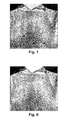
- the figure 1 is a thermal image obtained from a bolometric detector of the state of the art based on amorphous silicon implementing the teachings of the document FR 2 936 052 and illustrating the phenomenon of over-correction.
- the image of the figure 1 is obtained after a correction "two points" of the state of the art, after the offsets table was corrected while the camera, and therefore the shutter, had an average temperature of 60 ° C.
- the observed scene has an average temperature of 30 ° C.
- the gray scale of this image assigns a clear tone to the highest temperatures, the overall dynamics of the image in terms of scene temperature being of the order of 4 ° C.
- the dark spots are the "ghost images" before the two-point correction, coming from the presence of the sun in the image field of the detector during an implementation prior to the acquisition of the image of the figure 1 , according to various durations of exposure, at several points of the retina. These spots would appear in very clear contrast in the absence of correction, but appear in dark contrast on the corrected image, which means that these spots are over-corrected.
- the object of the present invention is therefore to propose a method for correcting the output signals of a bolometric detector, capable of substantially maintaining the initial accuracy of calibration over the entire life of the detector, without residual ghost images (artifacts of imaging) in case of excessive irradiation, despite the temporal and / or spatial drifts inherent to the bolometric material used in the detector, and in all the operational conditions of the camera in terms of ambient temperature.
- the subject of the invention is a method for correcting a gain table used in a correction of a response dispersion of resistive bolometers of a retina of resistive bolometers suspended over a substrate of a bolometric detector, said correction being applied to raw read signals from said bolometers, and each gain of the pay table being associated with a bolometer of the retina.
- the invention also relates to a bolometric detector comprising means for implementing the aforementioned method.
- the inventors have found that there is a relation between the value of the activation energy at least in the case of a bolometric material of amorphous silicon or silicon-germanium alloy and its electrical resistance. .
- the variation of the electrical resistance caused by a drift of the intrinsic characteristics of the bolometric material it is thus possible to estimate a corresponding variation of the coefficient TCR , and thus to re-calibrate the table of gains without implementing classical empirical re-calibration procedures based on reference black bodies.
- the invention therefore advantageously exploits said relationship. It will be understood that there are many ways of exploiting a mathematical relation as a function of the signals available at the output of the reading circuits, the computing power or the memory space of the on-board calculation units of the cameras, the type of analog circuit used, etc.
- the invention therefore covers the direct or indirect exploitation of this relationship in the context of the determination of a pay table.
- the invention implements size estimators, it being understood that these quantities are generally not directly measured, but rather estimated as a function of the signals available at the output of the retina and of various operating parameters of the detector, such as, for example parameters relating to the type of polarization used, or the type of architecture used to "read" the bolometer of the retina.
- the invention involves temperatures.
- the various relationships relate, or derive directly, from the temperature behavior of the bolometers themselves.
- the temperatures are those of the bolometers. Measuring the temperature of a bolometer is typically done using a measure of its resistance. However, it will then be impossible to discriminate the effect of the characteristic drift of the bolometers that is to be corrected. In this context, it is necessary to estimate this temperature by another means.
- a temperature probe may be provided near each bolometer, or one or more temperature probes may be provided for measuring the temperature of the substrate at one or more points thereof.
- the membranes of the bolometers are in thermal relationship with the substrate that carries them, and are therefore in equilibrium therewith, that is to say at an average temperature close to that of the substrate.
- the term "average temperature” means the effective temperature on a time scale, for example from a few seconds to a few minutes. It is known that the instantaneous temperature (on the scale typically of a few microseconds) of the membrane of a bolometer is capable of rapid variations of a few degrees during the electric reading pulse, under the effect of the Joule heating (also known as self heating ) which occurs once per frame in the most common case of line-by-line scanned polarization signal formation, as described later.
- the steady-state equilibrium (after several frames) between the self-heating phases related to the reading, and the thermal relaxation between frames towards the temperature of the substrate, leads to consider an average temperature generally greater by a few degrees than to that of the substrate. This difference also appears in case of continuous polarization, for which the average and instantaneous temperatures are equivalent.
- This average temperature difference is substantially constant, at least until the reading stimuli are changed. In particular, it appears as much at the so-called "previous” instant, as at the instant called “acquisition” of the signals in the preceding statement, so that it is not necessary in the general case of to know it to obtain a very good correction according to the invention. If it were necessary, for example, for the refinement of the correction, this difference could be estimated and integrated into the implementation of the method according to the invention, for example in the form of correction of the quantities T ref and T shut .
- the temperature of the bolometer depends on the incident radiation, that is to say on the temperature of the observed scene, so that this scene temperature contributes to defining the average temperature of the bolometer.
- this contribution remains very small compared to that of the substrate which carries it, usually of the order of a hundred times less. It follows that at least in the case where the so-called “prior” instants and “acquisition” signals correspond to scenes whose temperature is not very far from the temperature of the bolometers, for example less than 20 ° C, there is no substantial disturbance of the quality of the correction according to the invention.
- This condition is typically achieved when the camera is equipped with a shutter, since the inside of the camera is usually roughly insulated.
- the substrate itself may have a higher average temperature than other parts of the camera, including the shutter if there is one, because of the heat dissipation specific to its operation.
- the temperature of the bolometers is thus approximated by the temperature of the substrate, which constitutes a satisfactory estimate within the scope of the invention.
- the measurement of the temperature of the substrate at a point thereof can be considered, from the point of view of the bolometers, as a satisfactory approximation of their temperature.
- the temperature of the bolometers and the temperature at a point on the substrate, the nature of the temperatures used appearing distinctly from the context.
- the temperature of the substrate may also be referred to as the "focal plane temperature” since the substrate is placed in the focal plane of an optical equipping the bolometric detector or "temperature of the detector ".
- this estimate is obtained by means of an interpolation model between the points of the array of probes.
- T ref and T shut appearing in the derived expressions according to the invention, in the case of implementation of one of the preceding special provisions or their variants that the person skilled in the art will be able to put in place without departing from the The spirit of the invention is to be replaced by tabulated quantities T ref (i , j) and T shut (i , j).
- the application of a pay table is intended to substantially cancel the effect of the gross response dispersion Resp of each bolometric element of the retina around the average value. Re sp responses from all the elements of the retina.
- the earnings table is "normalized", that is to say that its average value is conventionally equal to 1.
- the average responsivity Re sp calibrated as explained above makes it possible to match the corrected signal, if this is necessary for the application (case of thermography for example), a scene temperature.
- Re sp averages at several temperatures characteristic of the camera, or more easily, of the focal plane ( TPF ).
- TPF responsivity curve
- the direct knowledge of the evolution of the calibration without it being necessary to measure the variations with the temperature is thus advantageous.
- the scalar N can be directly exploited as a relevant correction of the average response, that is to say implemented at the level of the relation (3).
- the document FR 2 936 052 does not use normalized gain tables G (i, j) which contain only the relative dispersion of responsivity, but rather to dimensioned tables of responsivity (or sensitivity S ), directly connecting the signals formed from each element from the retina to changes in the temperature of the scene.
- the quantities S (i, j) of the prior document therefore correspond to the quantities G (i, j).
- the N factor carries the global drift corrections of bolometric retinal characteristics, and / or average temperature drift in unregulated systems.
- this one expresses a double dependence of the responsivity vis-à-vis the bolometric material used, namely on the one hand a dependence as a function of the resistance R ac , and on the other hand a dependence according to the coefficient of variation in temperature TCR.
- the concept underlying the invention is to also take into account the dependence of responsivity as a function of the TCR coefficient in order to correct "second order" global or local drifts of the retina.
- This operation also requires acquiring the coefficients TCR at the temperature T shut at the time of closing the shutter. Since the TCR coefficients are strongly temperature dependent, the direct acquisition of their value in service requires carrying the focal plane of the camera, and therefore the retina, at two different temperatures, for example and typically by means of a Peltier module ( or “TEC” for " t hermo e lectric c ooler "). The TCR values of each bolometer are then extractable from two closed-shutter resistance measurements obtained at these two temperatures. In addition to the crippling fact that more and more commercial detectors are devoid of Peltier module, this operation is necessarily very time consuming, and would be very delicate at the operating level to obtain the required precision, since it is sought a correction "of the second order ".
- TEC Peltier module
- the invention thus proposes a method of second-order correction of global or local drifts of the retina which is also valid for the non-temperature-regulated detectors and which does not require that the measurements be made at the same temperature, although obviously the invention is also perfectly applicable under these conditions.
- the invention proposes to determine the gain table at the current temperature of the detector and to make disappear in the analytical model or models used any reference to the coefficients TCR.
- the invention is based on a previously acquired table of gains, and this even if this table was acquired at another temperature, including a temperature far removed from the current temperature of the detector. As will be detailed later, this working hypothesis is surprisingly very little detrimental to the quality of the second-order correction of drifting bolometers.
- the activation energy Ea depends of various intrinsic characteristics of the particular material considered, and that if these characteristics do not change, that is to say that if the material does not undergo drift, the activation energy Ea is substantially constant in temperature on the extended operating conditions of the detectors.
- the Applicant has found that the activation energy Ea substantially reversibly and reproducibly tracks the resistivity of the bolometric material, when it is caused to change for a reason other than a change in temperature. For a given material temperature, it is therefore possible to estimate the variation of the activation energy Ea of a bolometer using the variation of the resistance R ac thereof.
- the value of the factor K is for example calibrated experimentally for the material used for the development of the retina, by imposing a deliberate drift of various amplitudes to one or more bolometers of a calibration device, by measuring the resistances and the activation energies associated with these various drift states, and extracting the K- factor from these measurements, by the usual methods of linearization of relations (8) or (9).
- a value of the factor K of the order of 0.055 eV is typically relevant.
- other values in this order of magnitude may be better suited.
- the relations (8) and (9) do not impose a predefined generic link between the value of the resistance R ac and the value of the coefficient TCR or the value of the activation energy Ea.
- the relations (8) and (9) are in no way a reformulation of the law of Arrhenius expressed by the relation (5).
- the asymptotic resistance R ac0 and the activation energy Ea do not have a fixed or predetermined value and depend on the particular and momentary state of the bolometric material.
- the inventors have found that the implementation of the unique empirical relations (8) and (9) between the activation energy E a and the resistance R ac to produce the second-order gain correction object of the invention, remains valid at least on the extent of variation of R ac related to drift bolometers, found by the Applicant as being in the most extreme cases ordinarily incurred of the order of 10% of the value of the resistance R ac bolometers when commissioning the camera.
- the ratios ⁇ ( i , j ) and ⁇ ( i , j ) are respectively denominated first-order and second-order correction factors of the drifts sustained by the bolometers.
- Embodiments according to the invention will now be described applied to a particular bolometric detector which imposes particular signals S (i , j) or NC (i , j) because of the electronic circuitry implemented. It is however specified that the particular parameters and quantities which are then used in relation to this circuitry are in no way limiting and represent only a particular application of the invention.
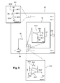
- the figure 2 schematically illustrates a bolometric detector according to the invention.
- This detector is unregulated in temperature, the temperature of its focal plane is therefore free to evolve, and detects the radiation of a scene to be observed in the infrared range.
- the detector comprises a matrix 10 of elementary thermal detectors, or bolometers, each comprising a bolometric membrane suspended above a substrate by supporting arms, polarization and thermal insulation.
- a reading circuit 20 and at least one temperature probe 30 are also formed in the substrate, and the suspended diaphragms of the bolometers together form a matrix retina disposed in the focal plane of an optic 40.
- a controllable shutter 50 is further provided in the optical path between the optics 40 and the matrix 10 of bolometers.
- the read circuit 20 provides a digital video stream representative of the thermal image of the observed scene formed by the optics 40, and the temperature probe 30 provides a digitized signal representative of the measured temperature and associated with the video stream.
- the management of the output signals of the circuit 20 is for example made by sampling-blocking then multiplexing using a circuit 60, in a manner known per se of the state of the art.
- the output data of the read circuit 20 constitute "raw" data, that is to say without analog or digital processing to correct the defects of the bolometers.
- a pixel of an image of the video stream delivered by the circuit 20 thus corresponds to the raw value S (i , j) or NC (i , j) (in front of a uniform scene) issuing from a bolometer.
- the imaging bolometers 1011 are usually constituted by a membrane suspended by support arms above the substrate in which are formed the various electronic elements necessary for reading.
- the bolometric material of the membranes is amorphous silicon (a-Si) or an amorphous silicon-germanium alloy (a-Si x Ge 1-x ).
- Each elementary point 101 of the matrix 10 furthermore comprises a reading switch 1012 , controllable by means of a " Select " signal and connected to the inverting terminal (-) of the operational amplifier 2021 of the associated circuit 202 , and a first NMOS transistor 1013 of injection, whose gate is driven by a voltage VFID so as to impose a voltage Vac across the bolometer 1011, whose source is connected to a terminal of the bolometer 1011, and whose drain is connected to the another terminal of the reading switch 1012 .
- the other terminal of the bolometer 1011 is connected to a constant low voltage VDET , for example the mass of the detector.
- Each compensation circuit 201 of the common mode current comprises a resistive compensation bolometer 2011 made of the same material as the imaging bolometer 1011, of electrical resistance R av , essentially insensitive to radiation from the scene, for example in that it has a low thermal resistance towards the substrate, and is provided, optionally or alternatively, with an opaque screen 2012.
- the compensation bolometer 2011 is connected to one of its terminals at a predetermined voltage VSK and to the one of its terminals, at the source of a second PMOS injection transistor 2013 of the circuit 201 whose gate is driven by a voltage GSK so as to impose a voltage V av across the bolometer 2011.
- the compensation circuit 201 also optionally comprises a resistance measuring switch 2014, controllable by the timing circuit 203 by means of a signal " Der2 ", and arranged between the drain of the Injection transistor 2013 and the inverting input (-) of the operational amplifier 2021 of the associated integration circuit 202 .
- a resistance measuring switch 2014 controllable by the timing circuit 203 by means of a signal " Der2 ", and arranged between the drain of the Injection transistor 2013 and the inverting input (-) of the operational amplifier 2021 of the associated integration circuit 202 .
- This switch will be described in more detail below according to the modes of implementation of the invention.
- the polarities of the pixels 101 and the circuits 201 can be reversed by means of inversion of the type of the MOS transistors.
- a compensation circuit 201 and the pixels 101 of the column of the matrix 10 associated with the compensation circuit being connected to a current summation point C connected to the inverting input "-" of an operational amplifier 2021, the potential of this summation point is maintained at a reference potential equal, at an offset voltage, to the potential VBUS .
- all the bolometers 1011 of the same line of the matrix 10 are polarized and "read" simultaneously, and the whole of the matrix 10 is scanned line by line by means of a sequential addressing of the lines, a compensation circuit 201 being common to each pixel 101 of the same column.
- the resistance measuring switches 2014 of the compensation circuits 201 are in their closed state and the reset switch 2023 of each integration circuit 202, which is closed during a preliminary reset cycle of the capacitor 2022, is switched to its open state by the timing circuit 203. The latter then closes. the switch 1012 for selecting the pixels 101 of the line being read.
- the difference between the current i ac crossing an imaging bolometer 1011 and the current i av through the associated compensation bolometer 1012 is then integrated by the capacitor 2022 of the corresponding circuit 202 .
- T int When a predetermined integration time T int has elapsed since the closing of the read switches 1012, the timing circuit 203 then opens them.
- the difference between the electrical resistance of the imaging bolometer 1011 and the associated compensation bolometer resistance 2011 , which induces the current difference at the input of the integration circuit 202, is then essentially representative of the variation ⁇ R ac of the electrical resistance R ac of the imaging bolometer 1011 induced by the radiation from the scene and incident on it .
- the voltages V out of the line being read are sent to the circuit 60 for sampling - blocking and multiplexing.
- the raw output signal NC associated with an imaging bolometer 1011 is, in the example illustrated here, the sampled value of the voltage V out .
- the substrate temperature signal (s) produced by the temperature sensor (s) 30 are also inserted into the output data stream of the multiplexer 60 according to known techniques.
- Such a bolometric detector structure is conventional and will not be explained in more detail later.
- the detector according to the invention also comprises a quick calculation circuit 70, such as a DSP (for "d igital s ignal p rocessor") connected to the output of the read circuit 20.
- the calculation circuit 70 applies to each image of the output stream of the reading circuit 20 has a two-point correction of offset and gain in order to correct the offset and gain dispersions of the bolometers 1011 of the matrix 10 by means of a d 801 offsets and a gain table 802 of a memory unit 80 of the detector.
- a calculation circuit 90 receives the stream of corrected images and then determines a temperature ⁇ stage (or any quantity of interest at the output in relation to ⁇ scene if the application is not strictly thermographic) of the IR infrared radiation incident on each imaging bolometer 1011 as a function of the corrected signals at the output of the calculation circuit 70, of the responsivity Resp 809 of the detector 10 with respect to the temperature of the scene, stored in a memory unit 80, and the table of gains 802.
- a calculation unit 100 is also provided for updating the offsets tables 801 and 802 and is connected to the shutter 50, the read circuit 20, and the memory unit 80.
- the calculation unit 100 includes an internal clock 1001 and a memory 1002 for storing its intermediate calculations.
- the unit 100 is also adapted to receive update commands 1003 from the user of the detector.
- units 70, 80, 90, 100 can be implemented in one or more microprocessors, the emphasis being placed in the illustrated example on the functions implemented rather than on the equipment that could be used. to be really used.
- This first embodiment applies more generally to any type of detector implementing an estimate of the values of the resistances of the imaging bolometers 1011 or any quantities representative thereof. As will appear below, the determination of a new pay table is independent of the particular parameters of the read circuit.
- the method begins with a first phase 200 of factory calibration to obtain the initial data for the subsequent implementation of the determination of a new table of earnings according to the relationship (10).
- the calibration phase 200 begins with the acquisition, in 2001, of two raw signal tables of the bolometers 1011 of the retina 10, when the camera is arranged in front of two black bodies at uniform temperatures T1 and T2 , designated respectively by NC T1 (i, j) and NC T2 (i, j).
- the NC tables T1 (i, j) and NC T2 (i, j) are formed preferentially, as is known per se, from the average value of several successively acquired frames, typically at least ten successive frames, in order to filter the dispersions related to acquisition noise or inherent to the detector.
- one of the acquired tables for example the NC table T1 (i, j) , is stored as initial offsets table 801 in the memory 80.
- the algebraic average NC T 1 of the table NC T1 (i, j) which is also used in the correction "two points", is also stored in the memory space 801.
- the table NC T1 (i, j) and its mean NC T 1 are furthermore stored in a space 803 of the memory 80 as a table of raw reference signals NC ref ( i , j ) and reference average NC ref .
- the table G ref ( i , j ) is also stored as a reference pay table in a space 804 of the memory 80.
- the temperature of the substrate during this calibration operation is also stored as a reference temperature T ref in a space 805 of the memory 80. According to a more elaborate form of estimation of this quantity by means of several temperature probes, a shape Tabulated T ref (i , j) of the reference temperature T ref is established and stored in the space 805.
- the value of the resistances R ac_ref ( i, j ) of the imaging bolometers 1011 is calculated as a function of the parameters of the read circuit 20 in a manner known per se, for example by means of an implementation described in the document FR 2 936 052 in relation to the embodiment of the figure 5 of said document, by arranging the camera in front of the black body of temperature T 1 , and a corresponding resistor table is stored in a space 806 in the memory 80.
- the resistance measuring switches 2014 of the compensation circuits 201 are switched into their open state by the timing circuit 203, and the bolometer array 10 is read line by line.
- V out V bus + 1 VS int ⁇ 0 T int ' i ac i ⁇ j ⁇ t ⁇ dt
- T ' int is a reduced integration time selected not to saturate the capacitor 2022 when measuring the drift of an imaging bolometer 1011
- i ac ( i , j ) ( t ) is the instantaneous current flowing in the imaging bolometer.
- R ac_ref ( i , j ) measurements are applicable, even in the absence of the switch 2014, for example by successively applying two different VFID voltages, inducing two different V ac polarizations, or else imposing two integration times T int different.
- a linear first order relation is then obtained between the values V out obtained and the resistors R ac_ref (i , j) , from which a measure of the resistances R ac_ref ( i , j ), or at least a substantially proportional magnitude, is extracted, such as it will be described in more detail below.
- the average activation energy Ea ref bolometers 1010 of the retina 10 is stored in a space 807 of the memory 80.
- the reference activation energies Ea ref ( i , j ) of the bolometers 1011 are all asked equal to the average energy Ea ref .
- Ea ref 0.170 eV.
- the activation energy Ea ref ( i , j ) of each imaging bolometer is acquired in a manner known per se, for example by measuring the resistances R ac at two uniform focal plane temperatures, typically distant a few degrees C, and a reference activation energy table is stored in the space 807 of the memory 80.
- this prior activation energy measurement is more accurate because the temperature difference imposed between the two measurements of R ac is measured or modeled at any point in the retina.
- the coefficient K of the relations (8) and (9) is stored in a space 808 of the memory 80.
- K 0.055 eV in a wide range of temperatures around 30 ° C.
- the coefficient K is for example obtained by extracting, before the sequence of operations described here, the directing coefficient of the experimental points connecting the activation energy Ea to the logarithm of the resistances, measured on a component whose pixels have been locally modified. by intense illumination, and therefore for which the sensitive materials constituting the resistors R ac ( i , j ) have more or less modified.
- the extraction of the values of the coefficient K may, in addition possibly, be extended over the full range of temperatures of interest, so as to obtain the behavioral curve K (TPF) as a function of the temperature of the focal plane.
- TPF behavioral curve K
- This empirical behavioral relationship can then be expressed in analytical form, for example polynomial.
- the various coefficients necessary for the implementation of the invention are in this case also stored in the space 808.
- the parameter K is not critical in terms of correction quality, at least +/- 20%, even when the detector temperature varies in very large proportions, and / or that the bolometer considered derives, for example, from +/- 10% in resistivity (at constant temperature), which represents a really extreme case.
- the responsivity is calibrated over the entire operating temperature range of the camera, so that some points of the curve are established and memorized.
- Re sp ref f (T) , T ref being only a particular point in which the resistance table R ac_ref was acquired in 2003 .
- this step can be omitted if it is preferable to use the corrective scalar N of normalization of the tables of gains resulting from the implementation of the invention, at least in the case of bolometers based on amorphous silicon or silicon-germanium alloys.
- the process then continues with a second phase 300 implemented while the detector is in use.
- the second phase 300 comprises a step 3001 of switching on the detector which opens the shutter 50 and triggers a process 3002 for acquiring a video stream of the observed scene.
- the process 3002 comprises the acquisition, in 30021, of a raw signal table S (i, j) by the reading circuit 20, followed, in 30022, by a "two-point" correction of the table S (i , j) by the calculating circuit 70 according to the relation:
- S corr i ⁇ j BOY WUT 802 i ⁇ j .
- G 802 ( i , j ), NC 801 ( i , j ) and NC 801 are respectively the gain table stored in the space 802 of the memory 80, and the offsets table and its mean stored in the space 801 of the memory 80.
- step 30023 loops back to step 30021 for acquiring and processing a new raw signal table.
- the activation step 3001 triggers a process 3003 for updating the offsets table 801, the paytable 802 and the average responsivity 809 implemented. by the calculation unit 100.
- the process 3003 of updating includes a first test step 30031 of the occurrence of an update condition data.
- the calculation unit 100 tests whether an order has been issued by the user to carry out such an update, and / or whether the time elapsed since the last update is greater than a predetermined threshold duration. and / or if the temperature of the substrate delivered by the temperature sensor 30 is different from the temperature of the substrate during the last update of more than a predetermined threshold value.
- the computing unit may also implement a processing algorithm to determine whether the retina 10 has undergone intense illumination signifying a modification of the intrinsic characteristics of the bolometers thus overexposed, and therefore a possible drift thereof.
- the occurrence of a temperature update condition may take into account several of these signals, or combinations of these signals with each other or with other parameters deemed useful or relevant in this context of interest taking into account global or local variations of focal plane temperature.
- the process 3003 continues by closing, in 30032, the shutter 50. If the camera has no shutter, the system (and / or the user ) will engage the step 30032, after satisfaction of a condition of sufficient uniformity scene, or activate any system to standardize as much as possible the perceived image on the retina.
- a raw signal table NC shut ( i , j ) is then stored in the memory 1002 of the unit 100, this table being preferably formed of the average of several successive frames, for example ten.
- the temperature of the substrate T shut delivered by the sensor 30 at the time of acquisition of the table NC shut ( i , j ) and the mean algebraic NC shut of the NC shut ( i , j ) table are also stored in the memory 1002 of the unit 100.
- the process continues, in 30034, by the calculation by unit 100 of the resistance values R ac_shut (i , j) according to a method for example proposed in the document FR 2 936 052 according to the parameters of the read circuit 20, in a manner similar to that described in relation to step 2003 by closing the shutter 50.
- the resistance values R ac_ref ( i , j ) @ T shut are estimated as a function of the resistance values R ac_ref (i , j) , the activation energy or energies Ea ref and the temperature T ref stored in the memory 80, and the temperature T shut stored in the unit 100.
- This estimate is for example implemented using the relation (11) directly in this form, or at least one form digital or linearized thereof. It is understood that T ref and T shut can also be tabulated.
- the resistance values R ac_ref ( i , j ) @ T shut and R ac_shut (i , j) are stored in corresponding tables in the memory 1002 of the unit 100.
- first-order correction factors ⁇ i ⁇ j R ac_shut i ⁇ j R ac_ref i ⁇ j are calculated and stored by the unit 100.
- the first embodiment of the invention applies to detectors which make it possible to determine the value of the resistances of the bolometers. This determination may consist of a calculation performed as a function of the raw signals delivered at the output of the read circuit or by any other means.
- a detector comprising switches 2014 in compensation circuits 201 for measuring voltages V out associated only with imaging bolometers 1011.
- Other architectures for measuring resistance are possible.
- the capacitance C int value of the capacitors 2022 is increased so that they do not saturate during an integration of duration T int used during normal operation. of the detector.
- each integrator 202 comprises two capacitors, a first being selected by the timing circuit 203 when reading the imaging matrix 10, and the second being selected when measuring the resistance of the imaging bolometers 1011. .
- the architecture described in the document FR 2 936 052 in relation to figures 1 and 2 measuring the difference between the resistance of the imaging bolometers and known reference resistors, is used to measure the resistances of the imaging bolometers 1011.
- the detector described in particular in relation to the figure 3 remains however a particular application, although privileged, of the first embodiment.
- the first embodiment also applies to detectors having different polarization circuitry, for example current bias circuits or else different common mode compensation circuits.
- the first embodiment of course also applies to temperature-regulated detectors, in which case the measurement of the temperature of the substrate is optional, the temperature T shut being identical to the temperature T ref subject of the temperature control.
- the preceding relations are then simplified accordingly, and in particular do not include a temperature ratio and do not require the estimation of the values R ac_ref ( i , j ) @ T shut which are by definition equal to the values R ac_ref ( i , j ).
- the invention also applies to detectors which do not include software and / or hardware means for determining the values of the bolometer resistances, which makes it possible to apply the invention to detectors of the state of the art without modification. the detector itself or hardware and software proximity for example piloting and formatting raw signals.
- the value of the term ⁇ NC ( i , j) NC shut ( i , j ) -NC ref ( i , j ), between a current instant of substrate temperature T shut and a previous instant substrate temperature T ref , depends for a part of drift bolometers 1011 and therefore includes information on it.
- the second embodiment therefore proposes to extract from the term ⁇ NC ( i , j ) most of the component related to the intrinsic drift, that is to say excluding temperature variation, bolometers 1011.
- R av_shut (j) and R av_ref (j) are respectively the values of the 2011 compensation bolometer resistances associated with the j th column of the retina 10 at the instant of acquisition of the new playback signals shut NC (i, j) , and at the previous time of acquisition of NC read signals ref (i, j) .
- the second embodiment is based on the comparison of this term with the mean ⁇ NC ND associated with imaging bolometers 1011 not having drifted at the moment of acquisition of NC shut ( i , j ) and at the temperature T shut , namely forming the differences according to the relation: ⁇ ⁇ NC i ⁇ j - ⁇ ⁇ NC ND ⁇
- ⁇ NC ND ⁇ NC .
- a second variant which estimates more precisely ⁇ NC ND , and which is for example useful when the detector is subjected to repeated irradiations, or to a high optical field, which scan or concern a non-negligible relative surface of the retina, an identification of the bolometers having derived, and therefore bolometers n ' having not derived, is implemented.
- a software-controlled spatial selection of the imaging bolometers 1011 associated with the elements of the table of gains that have undergone a significant modification during the last update (s) of this table is implemented.
- the bolometers 1011 that have truly drifted are thus identified for the current update.
- the ⁇ value NC ND is then calculated by averaging the raw signals of non-drifting bolometers. A very precise estimate of the magnitude ⁇ NC ND is thus obtained, and therefore second-order corrections to be applied. In other words, it is proposed here to apply a selective spatial mask.
- ⁇ NC ND T int VS int ⁇ 1 R ac_shut ND i ⁇ j - 1 R ac_ref ND i ⁇ j ⁇ .
- V ac - ⁇ BC or R ac_ref ND i ⁇ j and R ac_shut ND i ⁇ j are respectively the values of the resistances R ac _ ref ( i , j ) and R ac_shut ( i , j ) at the moment of the acquisition of the NC read signals shut ( i, j ), and at the previous instant of acquisition of NC reading signals ref (i, j) of the well-known bolometers not drifting among all retinal bolometers, that is to say in the general case as indicated, the essential of the bolometer population.
- the dispersion of the resistors R ac_ref ( i , j ) is moderated, in particular because these values correspond to the resistances of the bolometers at the factory outlet while they have not undergone any drift. So, the term 1 R ac_ref i ⁇ j - 1 R ac_ref ND can be neglected.
- the ratio of the relation (23) represents a relative variation between the resistances of the non-drifting bolometers 1011 (represented by the average term in the numerator) and the resistances of the drifting bolometers (represented by the denominator table).
- the term ⁇ NC ND that appears in the operating terms D (i, j) is generally correctly approximated by the mean ⁇ NC .
- Thermographic calibration can however be obtained as usual with an initial series of factory acquisitions of average responsivity at various temperatures. In this case, it is not necessary to form and store in memory the normalization factor N and its components.
- the second embodiment begins with a factory calibration phase 400 comprising the steps 2001 to 2007 previously described.
- a factory calibration phase 400 comprising the steps 2001 to 2007 previously described.
- the resistance values R ac_ref ( i , j ) imaging bolometers 1011 that are available in the factory means necessary to obtain at step 2003 an estimate of their average value R ac_ref stored in the space 806 at the temperature T ref stored in the space 805 in the step 2002, and ensure that their dispersion is sufficiently limited to allow the satisfactory application of previously established corrections.
- the calibration phase further comprises a step 4008 for storing the parameters of the read circuit 20, for example in an additional memory space of the memory 80, namely the value T int of the integration duration, the value C int of the integration capacity 2022, and the value V ac of the bias voltage of the imaging bolometers 1011.
- This second phase comprises the step 3001 and the process 3002 previously described, as well as a process of updating 5003 of the 803 and 801 offsets and the 809 average responsivity tables .
- the update process 5003 includes the steps of test 30031, shutter closure 30032 and acquisition of raw signal table 30033, previously described.
- the table D ( i, j ) ⁇ NC ( i , j ) - ⁇ NC is calculated, and the average resistance value R ac _ ref @ T shut is estimated as previously described in step 30034 using the relation (11), all of these data being stored in corresponding tables in the memory 1002 of the unit 100.
- this process is enriched by a subprocess of spatial determination of resistances that have not drifted.
- This sub-process exploits, for example, a comparison of the terms of the last earnings table or tables previously established during the previous iterations of update of the earnings table, as previously mentioned.
- the mean ⁇ NC ND values ⁇ NC ( i , j) of these particular resistances is then calculated in place of ⁇ NC .
- the unit 100 also forms the means ⁇ and ⁇ if a "two-point" correction using an approximated normalized gain table according to relation (29) is implemented.
- a new pay table is then calculated by the unit 100.
- the "two-point" correction is implemented using an "exactly normalized” pay table calculated according to the relation (28), and the unit 100 calculates a new pay table according to this relationship.
- the "two-point" correction is implemented using an approximately normalized earnings table according to the relation (29), and the unit 100 calculates a new earnings table according to this relationship.
- the method then continues with the step 30037 for updating the data of the memory 80 previously described.
- the calculation of a new earnings table has been presented under a succession of elementary calculation steps for the sake of clarity.
- the new pay table can be calculated in one step or elementary steps can be grouped in one step.
- Embodiments have been described in which the offsets table is also updated.
- the update of the pay table requiring the acquisition of a raw signal table corresponding to the shutter, this table is advantageously acquired to also update the offsets table.
- this The day of the offsets table although privileged, is optional.
- updating the offsets table by simply replacing it is only one possibility among others.
- Other types of update of the offsets table can be implemented.
- Embodiments have been described using a shutter forming a substantially uniform radiation scene when closed.
- the use of a shutter not only makes it possible to obtain such a scene independently of the environment of the detector, but also makes it possible to obtain a temperature scene close to the point of view of the bolometers, the temperature of those and the substrate.
- no shutter is used, and the read signals used to perform the correction of the gain table are those corresponding to a scene observed by the detector.
- this scene should be substantially uniform, or rendered uniform at the focal plane, for example by means of a defocusing of the image, and preferably at a temperature of the order of that of the focal plane, typically distant from said temperature of less than 20 ° C.
- the figure 6 is a thermal image obtained from a bolometric detector according to the second embodiment under the same operating conditions as those described in connection with the figure 1 . As can be seen, the dark spots resulting from an insufficient correction of the state of the art are now perfectly corrected.
Abstract
Description
La présente invention a trait au domaine de l'imagerie et de la thermographie infrarouge bo lométrique.The present invention relates to the field of imaging and infrared thermography bo lométrique.
Plus précisément, la présente invention concerne un procédé de correction de la dérive de calibration d'un dispositif de détection infrarouge, ou détecteur, destiné à l'imagerie, ou à l'imagerie thermographique (mesure de température de la scène basée sur l'énergie thermique radiative reçue) d'un rayonnement infrarouge à partir d'une matrice de bolomètres résistifs dits d'imagerie.More specifically, the present invention relates to a method for correcting the calibration drift of an infrared detection device, or detector, intended for imaging, or thermographic imaging (measurement of the temperature of the scene based on the radiative thermal energy received) from infrared radiation from a matrix of so-called resistive imaging bolometers.
Dans le domaine de l'imagerie et de la thermographie infrarouge, il est classique de mettre en oeuvre des détecteurs fonctionnant au voisinage de la température ambiante, ce terme recouvrant par exemple des températures comprises entre - 40 °C et + 90 °C, dits « non refroidis ». Ces détecteurs peuvent être régulés en température au niveau de leur plan focal, typiquement à l'aide d'un module Peltier (« TEC » en anglais). Le plus généralement, le plan focal est au contraire libre de varier en température (ou « TEC-less » en littérature anglo-saxonne). Ces dispositifs utilisent la variation d'une grandeur physique d'un matériau approprié, en fonction de la température, au voisinage de 300K. Dans le cas le plus répandu des détecteurs dits bolométriques, cette grandeur physique est la résistivité électrique.In the field of infrared imaging and thermography, it is conventional to implement detectors operating in the vicinity of ambient temperature, this term covering, for example, temperatures between -40 ° C. and + 90 ° C., known as "Uncooled". These detectors can be regulated in temperature at their focal plane, typically using a Peltier module ( "TEC" in English). Most generally, the focal plane is instead free to vary in temperature (or " TEC-less " in Anglo-Saxon literature). These devices use the variation of a physical quantity of a suitable material, depending on the temperature, in the vicinity of 300K. In the most widespread case of so-called bolometric detectors, this physical quantity is the electrical resistivity.
Un détecteur élémentaire d'un tel dispositif de détection associe généralement :
- ■ des moyens d'absorption du rayonnement infrarouge et de conversion de celui-ci en chaleur ;
- ■ des moyens d'isolation thermique du détecteur, de telle sorte à permettre à celui-ci de s'échauffer sous l'action du rayonnement infrarouge ;
- ■ des moyens de thermométrie qui, dans le cadre d'un détecteur bolométrique, mettent en oeuvre un élément résistif ;
- ■ et des moyens de lecture des signaux électriques fournis par les moyens de thermométrie.
- Means for absorbing infrared radiation and converting it into heat;
- ■ thermal insulation means of the detector, so as to allow it to heat up under the action of infrared radiation;
- Thermometric means which, in the context of a bolometric detector, implement a resistive element;
- And means for reading the electrical signals supplied by the thermometry means.
Les détecteurs destinés à l'imagerie infrarouge de ce type sont classiquement réalisés sous la forme d'une matrice bidimensionnelle de détecteurs élémentaires, ou bolomètres, chaque détecteur élémentaire de ladite matrice étant formé d'une membrane suspendue via des bras de soutien au dessus d'un substrat support de fabrication collective. Une telle matrice de détecteurs élémentaires est usuellement désignée sous l'expression de « rétine » d'imagerie.The detectors intended for infrared imaging of this type are conventionally made in the form of a two-dimensional matrix of elementary detectors, or bolometers, each elementary detector of said matrix being formed of a membrane suspended via support arms above a collective manufacturing support substrate. Such a matrix of elementary detectors is usually referred to as the "retina" imaging.
Il est par ailleurs ménagé dans le substrat, usuellement en silicium, des moyens électroniques d'adressage séquentiel des détecteurs élémentaires, et de formation d'un signal électrique en relation avec chaque bolomètre, puis éventuellement de traitement plus ou moins élaboré dudit signal. L'ensemble de l'électronique directement connectée aux bolomètres est connu sous l'appellation « circuit de lecture » (ou désigné par l'acronyme anglo-saxon ROIC pour « Read Out Integrated Circuit »).It is also provided in the substrate, usually made of silicon, electronic sequential addressing means elementary detectors, and forming an electrical signal in relation to each bolometer, then possibly more or less developed processing of said signal. All of the electronics directly connected to the bolometers are known as the "reading circuit" (or designated by the acronym ROIC for " R ead O ut I ntegrated C ircuit ").
Pour obtenir l'image d'une scène par l'intermédiaire de ce détecteur, l'image de la scène est projetée à travers une optique adaptée sur la matrice de détecteurs élémentaires, cette matrice étant placée dans le plan focal de l'optique. Des stimuli électriques cadencés sont appliqués par l'intermédiaire du circuit de lecture à chacun des détecteurs élémentaires, ou à chaque rangée de tels détecteurs, afin d'obtenir un signal électrique constituant l'image de la température atteinte par chacun desdits détecteurs élémentaires. Ce signal électrique directement lié à la résistance électrique de chaque détecteur élémentaire est utilisé par le système applicatif dans lequel le détecteur est intégré, pour former l'image thermique de la scène observée. Un tel système est appelé par convention « caméra ».To obtain the image of a scene via this detector, the image of the scene is projected through an optics adapted to the matrix of elementary detectors, this matrix being placed in the focal plane of the optics. Timed electrical stimuli are applied via the read circuit to each of the elementary detectors, or to each row of such detectors, in order to obtain an electrical signal constituting the image of the temperature reached by each of said elementary detectors. This electrical signal directly related to the electrical resistance of each elementary detector is used by the application system in which the detector is integrated, to form the thermal image of the observed scene. Such a system is conventionally called "camera".
Or, il est généralement observé que les matériaux bolométriques habituellement utilisés pour la fabrication d'un bolomètre d'imagerie, comme par exemple du silicium amorphe (a-Si), de l'alliage de silicium et de germanium (a-SixGe1-x) ou de l'oxyde de vanadium (VOx), présentent une dérive de leur résistance électrique plus ou moins prononcée en fonction du temps, pour des conditions d'exposition correspondant à l'usage normal du détecteur.However, it is generally observed that the bolometric materials usually used for the manufacture of an imaging bolometer, such as for example amorphous silicon (a-Si), silicon alloy and germanium (a-Si x Ge 1-x ) or vanadium oxide (VO x ) exhibit a more or less pronounced drift in their electrical resistance as a function of time, for exposure conditions corresponding to the normal use of the detector.
De manière encore plus critique, on constate également une dérive lorsque ces détecteurs ont été momentanément irradiés par une source très intense dans l'infrarouge, par exemple le soleil ou des sources radiatives puissantes (projecteurs, etc.). On parle dans ce cas plutôt de « rémanence », car la « dérive » ne concerne pas l'ensemble des points élémentaires du détecteur, mais seulement les zones correspondant à l'image de la source chaude à travers l'optique, qui forment une « image » rémanente après que la source à l'origine de cette empreinte ait disparu. On parle souvent dans ce cas « d'image fantôme » (ou « ghost image » ou encore « sunburn » dans la littérature anglo-saxonne), qui disparait plus ou moins rapidement avec le temps, car le matériau sensible des points d'image concernés par cette irradiation élevée a été modifié temporairement, puis revient plus ou moins rapidement vers son état avant irradiation. Ces artefacts sont préjudiciables à la qualité de l'image, et surtout dérèglent localement la calibration du détecteur, c'est-à-dire le rapport entre le signal en sortie et la température de la scène observée.Even more critically, there is also a drift when these detectors have been momentarily irradiated by a very intense source in the infrared, for example the sun or powerful radiative sources (projectors, etc.). In this case we speak rather of "remanence", because the "drift" does not concern all the elementary points of the detector, but only the zones corresponding to the image of the hot source through the optics, which form a "Image" after the source of the footprint has disappeared. We often speak in this case "of image ghost "(or" ghost image "or" sunburn "in the Anglo-Saxon literature), which disappears more or less rapidly over time, because the sensitive material of the image points involved in this high irradiation has been temporarily modified, then returns more or less rapidly to its state before irradiation. These artifacts are detrimental to the quality of the image, and above all locally disturb the calibration of the detector, that is to say the ratio between the output signal and the temperature of the scene observed.
Dans le cadre de la présente invention, le terme général de « dérive » d'un bolomètre caractérise le fait que, pour des conditions environnementales et de fonctionnement données, désignées ci-après par l'expression « conditions de référence », comme par exemple le rayonnement incident sur le bolomètre, la température ambiante pour celui-ci (température interne de la caméra) et les signaux électriques de lecture, les caractéristiques électriques du bolomètre se sont écartées au cours du temps de leur valeur initiale, dites de référence, qui se manifestent dans de telles conditions, notamment lors d'une opération particulière d'acquisition en usine dite de calibration, avant la mise en service opérationnelle du détecteur.In the context of the present invention, the general term "drift" of a bolometer characterizes the fact that, for given environmental and operating conditions, hereinafter referred to as "reference conditions", for example the incident radiation on the bolometer, the ambient temperature for it (internal temperature of the camera) and the electrical reading signals, the electrical characteristics of the bolometer have deviated over time from their initial value, referred to as reference, which are manifested in such conditions, especially during a particular acquisition operation factory called calibration, before the operational commissioning of the detector.
Dans le cadre de l'invention, l'écart constaté entre le signal obtenu lors de l'opération de calibration et le signal qui serait obtenu à un instant quelconque ultérieur lors de la vie du détecteur s'il était replacé exactement dans les mêmes conditions, est appelé « dérive », qu'il s'agisse d'une variation liée à une évolution lente, en général uniforme spatialement, des caractéristiques de sensibilité de l'ensemble des bolomètres du détecteur, en relation avec la relative instabilité naturelle des matériaux thermométriques traditionnellement mis en oeuvre, ou des variations beaucoup plus rapides (lors de leur apparition, puis de leur relaxation ultérieure) distribuées spatialement et variables temporellement, résultant de l'observation trop prolongée d'une source de rayonnement intense.In the context of the invention, the difference observed between the signal obtained during the calibration operation and the signal that would be obtained at any later time during the life of the detector if it was replaced exactly under the same conditions , is called "drift", whether it is a variation linked to a slow evolution, generally uniform spatially, of the sensitivity characteristics of all the bolometers of the detector, in relation to the relative natural instability of the materials thermometrics traditionally used, or much faster variations (at their onset, then their subsequent relaxation) spatially distributed and temporally variable, resulting from too prolonged observation of a source of intense radiation.
Pour bien introduire ce qui suit, il convient de détailler le processus dit de calibration le plus courant de l'état de la technique.To properly introduce the following, it should detail the so-called process of calibration most common state of the art.
Très généralement, ce processus de calibration comporte l'élaboration des paramètres bidimensionnels de corrections (usuellement appelés « tables ») d'offsets et de gains de la rétine matricielle qui sont ensuite utilisées au cours du fonctionnement du détecteur pour corriger les dispersions des caractéristiques des bolomètres.Very generally, this calibration process comprises the elaboration of two-dimensional parameters of corrections (usually called "tables") of offsets and gains of the matrix retina which are then used during the operation of the detector to correct the dispersions of the characteristics of the bolometers.
La table d'offsets est obtenue en mesurant et mémorisant l'ensemble des signaux de sortie obtenus devant une première scène de température uniforme (par exemple un corps noir de référence porté à une première température T1). Le signal de sortie (ou niveau continu) est désigné par NCT1 , et le signal particulier d'un bolomètre de coordonnées (i,j) dans la matrice de bolomètres est désigné par NCT1(i,j). La table d'offsets rassemble ainsi simplement l'ensemble des valeurs NCT1(i,j), qui représentent la distribution (la dispersion) du signal de sortie dans ces conditions de référence.The offsets table is obtained by measuring and memorizing all of the output signals obtained in front of a first uniform temperature scene (for example a reference blackbody brought to a first temperature T1 ). The output signal (or n evel ontinu c) is designated by NC T1, and the particular signal of a coordinate bolometer (i, j) in the array of bolometers is designated by NC T1 (i, j). The offsets table thus simply collects the set of NC values T1 (i, j) , which represent the distribution (dispersion) of the output signal under these reference conditions.
Le détecteur est ensuite placé devant une seconde scène de température uniforme différente, par exemple un second corps noir de référence porté à une seconde température T2, et une nouvelle table NCT2(i,j) est acquise et mémorisée.The detector is then placed in front of a second scene of different uniform temperature, for example a second reference black body brought to a second temperature T2 , and a new table NC T2 (i, j) is acquired and stored.
La table de gains de référence Gref(i,j) définie par la relation : 
La table Gref (i,j) représente la distribution (dispersion) relative de la réponse ou responsivité (« responsivity » dans la littérature anglo-saxonne) de l'ensemble des bolomètres de la rétine.The table G ref ( i , j) represents the relative distribution (dispersion) of the response or responsivity ("responsivity" in the Anglo-Saxon literature) of all bolometers of the retina.
Ces tables d'offsets et de gains, résultats de la calibration, sont mémorisées dans la caméra et utilisées, après sa mise en service, par une unité de calcul intégrée à la caméra pour pratiquer la traditionnelle « correction deux points » de chaque signal brut S(i,j) de chaque trame d'image, pour obtenir le signal corrigé Scorr(i,j) selon la relation : ![]()
![]()
Chaque signal brut S(i,j) est ainsi corrigé de son écart individuel par rapport à la moyenne de l'imageur en termes d'offset et de gain.Each raw signal S (i, j) is thus corrected for its individual deviation from the average of the imager in terms of offset and gain.
Habituellement, la caméra est pourvue d'un obturateur (« shutter »), interposé entre l'optique et le plan focal sensible, destiné à former l'équivalent d'une scène thermique uniforme à la température de l'obturateur. Lorsqu'il est jugé que le signal de sortie Scorr (i,j) n'est plus assez précis, par exemple à cause d'une dérive de température ou de la dispersion de température du plan focal, notamment pour les détecteurs « TEC-less » dépourvus de régulation de température, ou en raison des petites dérives individuelles ou globales des bolomètres, l'obturateur est activé, et la table d'offsets NCT1 est mise à jour, par exemple remplacée, par une nouvelle table NCshut des signaux bruts de sortie correspondant à l'obturateur fermé.Typically, the camera is provided with a shutter ( "shutter"), interposed between the optical and sensitive focal plane, for forming the equivalent of a uniform thermal scene at the temperature of the shutter. When it is judged that the output signal S corr ( i , j ) is no longer accurate enough, for example because of a temperature drift or of the focal plane temperature dispersion, in particular for the " TEC " detectors -less "without temperature regulation, or because of the small individual or global drifts of bolometers, the shutter is activated, and NC T1 offsets table is updated, for example replaced, by a new table NC shut raw output signals corresponding to the closed shutter.
L'usage traditionnel d'un obturateur procure ainsi un moyen simple et précis de formation de tables d'offsets de bonne qualité. Cependant l'observation d'une scène naturellement essentiellement uniforme à température ambiante, sans obturateur, ou la mise en oeuvre d'un moyen d'uniformisation du rayonnement de scène, par exemple par défocalisation de l'image, est également praticable dans le cadre de l'invention. Par la suite pour simplifier les notations, on écrira que la table NCshut « correspond à l'obturateur » sans que cela implique nécessairement la présence d'un obturateur mécanique.The traditional use of a shutter thus provides a simple and accurate way of forming offsets tables of good quality. However, the observation of a naturally essentially uniform scene at ambient temperature, without a shutter, or the implementation of a means of uniformizing the scene radiation, for example by defocusing the image, is also practicable in the context of of the invention. Subsequently to simplify the notations, it will be written that the NC shut table "corresponds to the shutter" without necessarily implying the presence of a mechanical shutter.
Les images obtenues après réouverture de l'obturateur sont alors de nouveau efficacement corrigées à l'aide de la nouvelle table d'offsets.The images obtained after reopening the shutter are then again efficiently corrected using the new offsets table.
Usuellement, il est considéré qu'il n'est pas nécessaire de mettre à jour la table de gains, car les phénomènes physiques à l'origine des dispersions relatives de réponse, par rapport à la valeur moyenne, ne varient pratiquement pas pendant toute la durée de vie du détecteur.Usually, it is considered that it is not necessary to update the earnings table, because the physical phenomena causing the relative dispersion of the response, with respect to the average value, do not vary substantially throughout lifetime of the detector.
En effet, la réponse Resp d'un bolomètre polarisé en tension, (c'est-à-dire soumis à une tension constante et sans autre contrainte extérieure sur le courant circulant dans le bolomètre), s'exprime de manière générique par l'expression suivante : 
- ■ Rac est la résistance électrique du bolomètre ;
- ■ A est l'aire du bolomètre dédiée à l'absorption du rayonnement ;
- ■ Rth est la résistance thermique entre la membrane du bolomètre et le substrat au dessus duquel elle est suspendue ;
- ■ ε est le coefficient de couplage (ou d'absorption) optique efficace de la membrane ;
- ■ TCR est le coefficient de variation de la résistance électrique du bolomètre en fonction de sa température ;
- ■ Φ est le flux d'énergie radiative incident sur le bolomètre ; et
- ■ θ scène est la température de scène
- ■ R ac is the electrical resistance of the bolometer;
- ■ A is the area of the bolometer dedicated to the absorption of radiation;
- ■ R th is the thermal resistance between the bolometer membrane and the substrate above which it is suspended;
- ■ ε is the effective optical coupling (or absorption) coefficient of the membrane;
- ■ TCR is the coefficient of variation of the electrical resistance of the bolometer as a function of its temperature;
- ■ Φ is the flow of incident radiative energy on the bolometer; and
- ■ θ scene is the scene temperature
La réponse est donc déterminée pour une part par des paramètres architecturaux ou de design, tels que l'aire A, la résistance thermique Rth , le coefficient ε, et divers paramètres de l'optique équipant le détecteur apparaissant dans le dernier terme Φ(θ scène ). Or, on constate que la valeur de ce premier groupe de paramètres, auquel on peut ajouter les paramètres du circuit de lecture destinés à la formation du signal brut S(i,j), n'évolue pas sensiblement dans le temps et reste donc sensiblement constante tout au long de la vie du détecteur.The answer is therefore partly determined by architectural or design parameters, such as the area A , the thermal resistance R th , the coefficient ε, and various parameters of the optics equipping the detector appearing in the last term Φ ( θ scene ) . However, it can be seen that the value of this first group of parameters, to which can be added the parameters of the read circuit intended for the formation of the raw signal S (i, j) , does not change substantially over time and therefore remains substantially constant throughout the life of the detector.
Un autre groupe de paramètres intervient cependant dans la réponse du bolomètre, sous la forme des caractères liés au matériau thermométrique de celui-ci, à savoir sa résistance électrique Rac (à travers sa résistivité ρ), et son coefficient de variation relative de résistance avec la température TCR défini par la relation : 
Ces paramètres de matériau sont eux susceptibles de dériver de manière significative, comme il a déjà été signalé. En particulier, la résistance électrique Rac des matériaux usuels en bolométrie (oxydes de vanadium et silicium amorphe essentiellement) peut intrinsèquement varier de quelques pourcents sur la durée de vie du détecteur. Cette résistance peut également varier sous l'effet d'un échauffement particulièrement élevé provoqué par une irradiation infrarouge intense et/ou prolongée, ce qui est plus préjudiciable en termes de qualité d'image du fait que la perturbation ne concerne en général qu'une partie de la rétine. Il se forme donc sur l'image une tache de contraste « artificielle » non liée à la scène, qui disparait après correction d'offset seul, c'est-à-dire après mise à jour de la correction « un point », mais sur laquelle la calibration thermographique initiale est faussée, car la table de gains initiale n'est plus exacte sur la partie de la rétine qui a été modifiée.These material parameters are likely to drift significantly, as has already been reported. In particular, the electrical resistance R ac of conventional bolometry materials (mainly vanadium oxides and amorphous silicon) can intrinsically vary by a few percent over the lifetime of the detector. This resistance can also vary under the effect of a particularly high temperature rise caused by intense and / or prolonged infrared irradiation, which is more detrimental in terms of image quality because the disturbance generally only concerns part of the retina. An "artificial" contrast spot is thus formed on the image that is not linked to the scene, which disappears after offset correction alone, that is, after updating the "one point" correction, but on which the initial thermographic calibration is distorted, because the initial table of gains is no longer exact on the part of the retina which has been modified.
Ces variations ou dérives de calibration, peuvent être significatives en regard de la précision des images ou mesures thermiques qu'on entend réaliser. Ainsi donc, la table de gains utilisée dans la correction « deux points » nécessite d'être re-calibrée régulièrement si l'on souhaite une qualité d'image constante au cours de la vie du détecteur.These variations or calibration drifts can be significant compared to the accuracy of the images or thermal measurements that are intended to be made. Thus, the pay table used in the "two-point" correction needs to be re-calibrated regularly if a constant image quality is desired during the life of the detector.
Il a ainsi été proposé des méthodes de correction de ces dérives, par exemple dans le document
Par détecteur en « service », il convient de comprendre que la correction peut être effectuée alors que la caméra est par exemple à la disposition de l'utilisateur, par une procédure ne faisant pas appel aux méthodes de calibration appliquées par le constructeur en usine, notamment à l'aide de corps noirs.By "service" detector, it should be understood that the correction can be performed while the camera is for example available to the user, by a procedure not using the calibration methods applied by the manufacturer in the factory, especially with the help of black bodies.
La correction pratiquée peut être globale (unique et valable sur l'ensemble de la rétine) ou individuelle (adaptée à chaque point sensible) dans le cas où la résistance de référence est le bolomètre lui-même. La table de gains ainsi actualisée est ensuite appliquée à la correction, par exemple numérique, des signaux bruts. Il est ainsi obtenu une correction substantielle des erreurs liées à la dérive de réponse.The correction practiced can be global (unique and valid throughout the retina) or individual (adapted to each sensitive point) in the case where the reference resistance is the bolometer itself. The thus updated discount table is then applied to the correction, for example numeric, of the raw signals. It is thus obtained a substantial correction of the errors related to the drift of response.
Cette méthode est efficace, en ce sens qu'elle élimine l'essentiel des écarts de calibration, et en cas de mise en oeuvre individuelle, également l'essentiel des dérives liées aux irradiations locales intenses.This method is effective in that it eliminates most of the differences in calibration, and in case of individual implementation, also the main drifts related to intense local irradiation.
Cependant, il est constaté que les perturbations spatiales de réponse de type « rémanents » faisant suite à une irradiation intense localisée ne sont pas parfaitement corrigées dans toutes les conditions de fonctionnement de la caméra. En effet, lorsque la température de l'obturateur lors de la calibration est proche de la température moyenne de la scène observée par la suite, l'image corrigée « deux points » qui résulte des tables d'offset et de gains actualisées est satisfaisante.However, it is found that the spatial disturbances of "remanent" type response following intense localized irradiation are not perfectly corrected in all operating conditions of the camera. Indeed, when the shutter temperature during calibration is close to the average temperature of the scene observed thereafter, the corrected "two-point" image resulting from the offset and updated earnings tables is satisfactory.
En revanche, lorsque la température de la caméra, et donc la température de l'obturateur, est éloignée de la température moyenne de scène, il subsiste après correction « deux points » une image fantôme bien visible des zones préalablement perturbées, en particulier sur des images à faible contraste thermique, qui tendent à être sur-corrigées, conduisant à une inversion du contraste local sur l'image après correction.On the other hand, when the temperature of the camera, and therefore the temperature of the shutter, is removed from the average scene temperature, there remains after a "two-point" correction a very visible ghost image of the previously disturbed zones, in particular on images with low thermal contrast, which tend to be over-corrected, leading to a local contrast reversal on the image after correction.
La
Les taches foncées sont les « images fantômes » avant la correction deux points, provenant de la présence du soleil dans le champ image du détecteur lors d'une mise en oeuvre antérieure à l'acquisition de l'image de la
Cet exemple du domaine de l'imagerie est également illustratif de la limitation de l'art antérieur dans le domaine de la thermographie. En effet, l'estimation de température de scène qui serait extraite des points situés dans les zones perturbées sera faussée par rapport à la mesure correcte fournie par les points environnants non perturbés.This example of the field of imaging is also illustrative of the limitation of the prior art in the field of thermography. Indeed, the estimate of the scene temperature that would be extracted from the points located in the disturbed areas will be distorted compared to the correct measurement provided by the undisturbed surrounding points.
Ces défauts d'imagerie et de calibration sont corrigeables au moyen d'une re-calibration du détecteur en usine, en réitérant le processus d'exposition devant deux corps noirs à deux températures de référence T1 et T2, pour déterminer une nouvelle table de gains comme précédemment décrit. Cependant, outre que cette opération complexe est impossible à mettre en oeuvre pour les systèmes en service, du fait qu'il faut replacer la caméra dans les mêmes conditions thermiques que lors de la calibration, il conviendrait de la reproduire de manière répétitive lors des phases de retour vers l'équilibre (dit relaxation) après irradiation excessive. De fait, cette solution n'est pas envisageable sans une mise hors service prolongée de la caméra.These imaging and calibration defects are correctable by means of a re-calibration of the detector at the factory, by reiterating the exposure process in front of two black bodies with two reference temperatures T1 and T2 , to determine a new table of gains. as previously described. However, besides this complex operation is impossible to implement for the systems in use, because it is necessary to replace the camera in the same thermal conditions as during calibration, it should be reproduced repetitively during phases back to balance (called relaxation) after excessive irradiation. In fact, this solution is not possible without a prolonged shutdown of the camera.
Le document
Il subsiste donc un besoin manifeste de disposer d'une méthode adéquate pour l'élimination substantielle des erreurs résiduelles de calibration, et plus précisément des artefacts nuisibles en imagerie et thermographie consécutifs à des périodes d'exposition excessive à un rayonnement thermique intense, toujours constatés après correction selon l'état de l'art.There is therefore still a clear need for an adequate method for the substantial elimination of residual calibration errors, and more specifically artifacts harmful to imaging and thermography resulting from periods of excessive exposure to intense thermal radiation, which are still observed. after correction according to the state of the art.
De plus, il subsiste un besoin de disposer d'un protocole de correction de dérive et desdits artefacts qui ne nécessite pas de recourir à des conditions particulières, nécessitant la mise hors service prolongée du détecteur.In addition, there remains a need for a drift correction protocol and said artifacts that does not require the use of special conditions, requiring the prolonged shutdown of the detector.
Il subsiste également un besoin de proposer un protocole de correction de dérive ou desdits artefacts applicable aux caméras en service pourvues d'une circuiterie de lecture standard de l'état de la technique, et de surcroît valide quelle que soit la mise en oeuvre thermique du détecteur, c'est-à-dire de type régulé en température de plan focal, ou non régulé (« TEC-Less »).There is also a need to propose a drift correction protocol or said artifacts applicable to cameras in service provided with a standard reading circuitry of the state of the art, and moreover valid regardless of the thermal implementation of the device. detector, that is to say of type regulated in focal plane temperature, or unregulated (" TEC-Less ").
Le but de la présente invention est donc de proposer une méthode de correction des signaux de sortie d'un détecteur bolométrique, capable de substantiellement maintenir la précision initiale de calibration sur toute la durée de vie du détecteur, sans images fantômes résiduelles (artefacts d'imagerie) en cas d'irradiation excessive, malgré les dérives temporelles et/ou spatiales inhérentes au matériau bolométrique utilisé dans le détecteur, et dans toutes les conditions opérationnelles de la caméra en termes de température ambiante.The object of the present invention is therefore to propose a method for correcting the output signals of a bolometric detector, capable of substantially maintaining the initial accuracy of calibration over the entire life of the detector, without residual ghost images (artifacts of imaging) in case of excessive irradiation, despite the temporal and / or spatial drifts inherent to the bolometric material used in the detector, and in all the operational conditions of the camera in terms of ambient temperature.
A cet effet, l'invention a pour objet un procédé de correction d'une table de gains utilisée dans une correction d'une dispersion en réponse de bolomètres résistifs d'une rétine de bolomètres résistifs suspendue au dessus d'un substrat d'un détecteur bolométrique, ladite correction étant appliquée à des signaux bruts de lecture issus desdits bolomètres, et chaque gain de la table de gains étant associé à un bolomètre de la rétine.To this end, the subject of the invention is a method for correcting a gain table used in a correction of a response dispersion of resistive bolometers of a retina of resistive bolometers suspended over a substrate of a bolometric detector, said correction being applied to raw read signals from said bolometers, and each gain of the pay table being associated with a bolometer of the retina.
Selon l'invention, le procédé consiste :
- ■ à acquérir des signaux de lecture de la rétine correspondant à une scène sensiblement uniforme en température ;
- ■ à calculer une table de correction g de la table de gain en fonction des signaux de lecture acquis selon la relation :

- ■ et à corriger la table de gains selon la relation :

expressions dans lesquelles :- ■ (i,j) représentent les coordonnées des bolomètres dans la rétine et les tables ;
- ■ Gref et Gshut sont respectivement la table de gains avant correction et la table de gains corrigée ;
- ■ Rac_shut(i,j) est la valeur de résistance du bolomètre de coordonnées (i,j) à l'instant d'acquisition des signaux de lecture ;
- ■ Rac_ref(i,j) est une valeur de la résistance du bolomètre de coordonnées (i,j) à un instant antérieur ;
- ■ TCRshut(i,j) est une valeur du coefficient de variation en température du bolomètre de coordonnées (i,j) à l'instant d'acquisition des signaux de lecture ;
- ■ TCRref(i,j) est une valeur du coefficient de variation en température du bolomètre de coordonnées (i,j) à l'instant antérieur ; et
- ■ N est un facteur scalaire de normalisation de la table de gains Gshut.
- ■ acquire retinal reading signals corresponding to a substantially uniform temperature scene;
- ■ calculating a correction table g of the gain table as a function of the reading signals acquired according to the relation:
- ■ and correct the earnings table according to the relationship:
expressions in which:- ■ ( i , j ) represent the coordinates of bolometers in the retina and tables;
- ■ G ref and G shut are respectively the earnings table before correction and the corrected earnings table;
- ■ R ac_shut (i, j) is the resistance value of the coordinate bolometer ( i , j ) at the acquisition time of the read signals;
- ■ R ac_ref (i , j) is a value of the resistance of the coordinate bolometer ( i , j ) at an earlier time;
- ■ TCR shut (i , j) is a value of the temperature variation coefficient of the coordinate bolometer ( i , j ) at the acquisition time of the read signals;
- ■ TCR ref (i , j) is a value of the temperature variation coefficient of the coordinate bolometer ( i , j ) at the previous instant; and
- ■ N is a scalar factor for normalizing the G shutdown table .
Le facteur N est avantageusement égal à la moyenne algébrique de tous les éléments du numérateur N(i,j) = g(i,j).Gref (i,j), auquel cas, on a : 
L'invention a également pour objet un détecteur bolométrique comportant des moyens de mise en oeuvre du procédé précité.The invention also relates to a bolometric detector comprising means for implementing the aforementioned method.
Selon un mode de réalisation de l'invention, le matériau bolométrique des bolomètres résistifs est du silicium amorphe ou un alliage de silicium-germanium, les valeurs Rac_ref(i,j) sont des valeurs de résistance des bolomètres pour une température moyenne Tref de ceux-ci, et le terme 

- ■ Tshut est une température moyenne des bolomètres à l'instant d'acquisition des signaux ;
- ■ K est un coefficient prédéterminé dépendant des bolomètres résistifs ;
- ■ Ea_ref est une valeur prédéterminée de l'énergie d'activation des bolomètres ;
- ■ In est le logarithme népérien ; et
- ■ Rac_ref (i,j)@Tshut est une valeur à l'instant antérieur de la résistance du bolomètre de coordonnées (i,j) pour la température Tshut .
- ■ T shut is an average temperature of the bolometers at the time of acquisition of the signals;
- K is a predetermined coefficient dependent on resistive bolometers;
- ■ E a_ref is a predetermined value of the activation energy of bolometers;
- ■ In is the natural logarithm; and
- ■ R ac_ref ( i , j ) @ T shut is a value at the previous time of the resistance of the coordinate bolometer ( i , j ) for the temperature T shut .
En d'autres termes, les inventeurs ont constaté qu'il existe une relation entre la valeur de l'énergie d'activation au moins dans le cas d'un matériau bolométrique en silicium amorphe ou en alliage de silicium-germanium et sa résistance électrique. En connaissant la variation de la résistance électrique provoquée par une dérive des caractéristiques intrinsèques du matériau bolométrique, il est donc possible d'estimer une variation correspondante du coefficient TCR, et donc de re-calibrer la table de gains sans pour autant mettre en oeuvre des procédures classiques de re-calibration empirique à base de corps noirs de référence.In other words, the inventors have found that there is a relation between the value of the activation energy at least in the case of a bolometric material of amorphous silicon or silicon-germanium alloy and its electrical resistance. . By knowing the variation of the electrical resistance caused by a drift of the intrinsic characteristics of the bolometric material, it is thus possible to estimate a corresponding variation of the coefficient TCR , and thus to re-calibrate the table of gains without implementing classical empirical re-calibration procedures based on reference black bodies.
L'invention exploite donc avantageusement ladite relation. On comprendra qu'il existe de nombreuses manières d'exploiter une relation mathématique en fonction des signaux disponibles en sortie des circuits de lecture, de la puissance de calcul ou de l'espace mémoire des unités de calcul embarquées dans les caméras, du type de circuit analogique utilisé, etc.The invention therefore advantageously exploits said relationship. It will be understood that there are many ways of exploiting a mathematical relation as a function of the signals available at the output of the reading circuits, the computing power or the memory space of the on-board calculation units of the cameras, the type of analog circuit used, etc.
L'invention couvre donc l'exploitation directe ou indirecte de cette relation dans le cadre de la détermination d'une table de gains. Notamment, l'invention met en oeuvre des estimateurs de grandeurs, étant entendu que ces grandeurs ne sont généralement pas directement mesurées, mais plutôt estimées en fonction des signaux disponibles en sortie de la rétine et de divers paramètres de fonctionnement du détecteur, comme par exemple des paramètres relatifs au type de polarisation utilisé, ou encore au type d'architecture utilisée pour « lire » les bolomètres de la rétine.The invention therefore covers the direct or indirect exploitation of this relationship in the context of the determination of a pay table. In particular, the invention implements size estimators, it being understood that these quantities are generally not directly measured, but rather estimated as a function of the signals available at the output of the retina and of various operating parameters of the detector, such as, for example parameters relating to the type of polarization used, or the type of architecture used to "read" the bolometer of the retina.
On notera par ailleurs que l'invention fait intervenir des températures. Comme il apparaîtra plus clairement ci-dessous, les diverses relations concernent, ou dérivent directement, du comportement en température des bolomètres eux-mêmes. En théorie donc, les températures sont celles des bolomètres. Mesurer la température d'un bolomètre se pratique typiquement à l'aide d'une mesure de sa résistance. Toutefois, il sera alors impossible de discriminer l'effet de la dérive de caractéristique des bolomètres qu'il est question de corriger. Il est dans ce contexte nécessaire d'estimer cette température par un autre moyen. Par exemple, une sonde de température peut être prévue à proximité de chaque bolomètre, ou une ou plusieurs sondes de températures peuvent être prévues pour mesurer la température du substrat en un ou plusieurs points de celui-ci. En effet, les membranes des bolomètres sont en relation thermique avec le substrat qui les porte, et sont donc en équilibre avec celui-ci, c'est-à-dire à une température moyenne proche de celle du substrat.It will be noted moreover that the invention involves temperatures. As will become clearer below, the various relationships relate, or derive directly, from the temperature behavior of the bolometers themselves. In theory, therefore, the temperatures are those of the bolometers. Measuring the temperature of a bolometer is typically done using a measure of its resistance. However, it will then be impossible to discriminate the effect of the characteristic drift of the bolometers that is to be corrected. In this context, it is necessary to estimate this temperature by another means. For example, a temperature probe may be provided near each bolometer, or one or more temperature probes may be provided for measuring the temperature of the substrate at one or more points thereof. Indeed, the membranes of the bolometers are in thermal relationship with the substrate that carries them, and are therefore in equilibrium therewith, that is to say at an average temperature close to that of the substrate.
On entend par « température moyenne » la température effective sur une échelle de temps par exemple de quelques secondes à quelques minutes. Il est connu que la température instantanée (à l'échelle typiquement de quelques microsecondes) de la membrane d'un bolomètre est susceptible de variations rapides de quelques degrés lors de l'impulsion électrique de lecture, sous l'effet de l'auto-échauffement par effet Joule (également connu sous l'expression de «self heating ») qui se manifeste une fois par trame dans le cas le plus fréquent de la formation de signal par polarisation en mode balayé ligne par ligne, tel que décrit ultérieurement. L'équilibre en régime établi (après plusieurs trames) entre les phases d'auto-échauffement liées à la lecture, et de relaxation thermique entre trames vers la température du substrat, conduit à considérer une température moyenne en général supérieure de quelques degrés par rapport à celle du substrat. Cette différence apparait aussi en cas de polarisation continue, pour lequel les températures moyenne et instantanée sont équivalentes.The term "average temperature" means the effective temperature on a time scale, for example from a few seconds to a few minutes. It is known that the instantaneous temperature (on the scale typically of a few microseconds) of the membrane of a bolometer is capable of rapid variations of a few degrees during the electric reading pulse, under the effect of the Joule heating (also known as self heating ) which occurs once per frame in the most common case of line-by-line scanned polarization signal formation, as described later. The steady-state equilibrium (after several frames) between the self-heating phases related to the reading, and the thermal relaxation between frames towards the temperature of the substrate, leads to consider an average temperature generally greater by a few degrees than to that of the substrate. This difference also appears in case of continuous polarization, for which the average and instantaneous temperatures are equivalent.
Cette différence de température moyenne est substantiellement constante, au moins tant que les stimuli de lecture ne sont pas modifiés. En particulier, elle apparait autant à l'instant dit « antérieur », qu'à l'instant dit « d'acquisition » des signaux dans l'exposé précédent, de sorte qu'il n'est pas nécessaire dans le cas général de la connaitre pour obtenir une très bonne correction selon l'invention. S'il était besoin à des fins par exemple de raffinement de la correction, cette différence pourrait être estimée et intégrée dans la mise en oeuvre de la méthode selon l'invention, par exemple sous forme de correction des grandeurs Tref et Tshut. This average temperature difference is substantially constant, at least until the reading stimuli are changed. In particular, it appears as much at the so-called "previous" instant, as at the instant called "acquisition" of the signals in the preceding statement, so that it is not necessary in the general case of to know it to obtain a very good correction according to the invention. If it were necessary, for example, for the refinement of the correction, this difference could be estimated and integrated into the implementation of the method according to the invention, for example in the form of correction of the quantities T ref and T shut .
De par son principe même, la température du bolomètre dépend du rayonnement incident, c'est à dire de la température de la scène observée, de sorte que cette température de scène contribue à définir la température moyenne du bolomètre. Toutefois, cette contribution demeure très faible devant celle du substrat qui le porte, ordinairement de l'ordre de cent fois moins. Il en résulte qu'au moins dans le cas où les instants dits « antérieurs » et d'« acquisition » des signaux correspondent à des scènes dont la température n'est pas très éloignée de la température des bolomètres, par exemple moins de 20 °C, il n'y a pas de perturbation substantielle de la qualité de la correction selon l'invention. Cette condition est typiquement obtenue lorsque la caméra est équipée d'un obturateur, du fait que l'intérieur de la caméra est usuellement grossièrement isotherme. Par « grossièrement », il est entendu par exemple que le substrat peut lui-même présenter une température moyenne plus élevée que d'autres parties de la caméra, dont l'obturateur s'il y en a un, du fait de la dissipation thermique propre à son fonctionnement.By its very principle, the temperature of the bolometer depends on the incident radiation, that is to say on the temperature of the observed scene, so that this scene temperature contributes to defining the average temperature of the bolometer. However, this contribution remains very small compared to that of the substrate which carries it, usually of the order of a hundred times less. It follows that at least in the case where the so-called "prior" instants and "acquisition" signals correspond to scenes whose temperature is not very far from the temperature of the bolometers, for example less than 20 ° C, there is no substantial disturbance of the quality of the correction according to the invention. This condition is typically achieved when the camera is equipped with a shutter, since the inside of the camera is usually roughly insulated. By "roughly" it is understood for example that the substrate itself may have a higher average temperature than other parts of the camera, including the shutter if there is one, because of the heat dissipation specific to its operation.
Ces petits écarts peuvent être négligés pour la mise en oeuvre satisfaisante de l'invention. Pour de plus gros écarts de température, on observe une correction de qualité inférieure mais qui permet cependant de réduire les phénomènes d'image fantôme décrit précédemment.These small differences can be neglected for the satisfactory implementation of the invention. For larger temperature differences, a lower quality correction is observed but which nevertheless makes it possible to reduce the ghosting phenomena described above.
De manière avantageuse, la température des bolomètres est donc approximée par la température du substrat, qui constitue une estimation satisfaisante dans le cadre de l'invention. Aussi donc, la mesure de température du substrat en un point de celui-ci peut être considérée, du point de vue des bolomètres, comme une approximation satisfaisante de leur température. Dans ce qui suit, pour des raisons de clarté et de concision, il ne sera donc pas fait de distinction particulière entre la température des bolomètres et la température en un point du substrat, la nature des températures utilisées apparaissant distinctement du contexte. En outre, et conformément aux notations usuelles du domaine, la température du substrat peut également être désignée sous l'expression de « température plan focal » puisque le substrat est placé dans le plan focal d'une optique équipant le détecteur bolométrique ou « température du détecteur ».Advantageously, the temperature of the bolometers is thus approximated by the temperature of the substrate, which constitutes a satisfactory estimate within the scope of the invention. Thus, the measurement of the temperature of the substrate at a point thereof can be considered, from the point of view of the bolometers, as a satisfactory approximation of their temperature. In the following, for the sake of clarity and brevity, therefore, no particular distinction will be made between the temperature of the bolometers and the temperature at a point on the substrate, the nature of the temperatures used appearing distinctly from the context. In addition, and in accordance with the usual notations of the field, the temperature of the substrate may also be referred to as the "focal plane temperature" since the substrate is placed in the focal plane of an optical equipping the bolometric detector or "temperature of the detector ".
Toutefois, dans le cas où un gradient spatial non négligeable de température, permanent ou variable de manière transitoire se manifesterait sur la portion de substrat portant la rétine sensible, il est avantageux de disposer plusieurs sondes de température en de multiples points du substrat permettant d'obtenir une estimation de la température du substrat à proximité de chaque bolomètre. Cette estimation est par exemple directement fournie de manière simple par le signal de la sonde la plus proche d'un bolomètre donné, avec une distribution spatiale des sondes selon un réseau régulier beaucoup moins dense que la matrice de bolomètres. Ce réseau est par exemple à maille carrée ou hexagonale, et étendu au moins sur une partie du substrat portant la rétine sensible.However, in the case where a non-negligible spatial gradient of temperature, which is permanent or transiently variable, would manifest itself on the substrate portion carrying the sensitive retina, it is advantageous to have several temperature probes at multiple points on the substrate allowing obtain an estimate of the temperature of the substrate near each bolometer. This estimate is for example directly provided in a simple manner by the signal of the probe closest to a given bolometer, with a spatial distribution of the probes in a regular network much less dense than the matrix of bolometers. This network is for example square mesh or hexagonal, and extended at least on a portion of the substrate bearing the sensitive retina.
De manière alternative plus raffinée si besoin, cette estimation est obtenue au moyen d'un modèle d'interpolation entre les points du réseau de sondes.In a more refined alternative way if necessary, this estimate is obtained by means of an interpolation model between the points of the array of probes.
De manière à limiter le nombre de sondes nécessaires à la formation d'une estimation de température locale du substrat suffisamment fine, et qui évite de manière avantageuse l'insertion de sondes dans l'emprise de la circuiterie régulière de lecture disposée dans la zone sensible de la rétine, il est disposé par exemple en divers points périphériques à la rétine sensible, une pluralité de sondes fournissant chacune une mesure locale de température du substrat. Le ou les signaux de température sont exportés vers la sortie de manière classique, par exemple et typiquement après numérisation et intégration au flux de données vidéo. L'estimation de la distribution spatiale de température du substrat au voisinage de chaque bolomètre est ensuite formée au moyen d'un modèle thermique du détecteur intégré dans l'algorithme de correction selon l'invention.In such a way as to limit the number of probes necessary for the formation of a sufficiently fine local substrate temperature estimate, and which advantageously avoids the insertion of probes in the right-of-way of the regular reading circuit arranged in the sensitive zone of the retina, it is arranged for example at various points peripheral to the sensitive retina, a plurality of probes each providing a local temperature measurement of the substrate. The temperature signal (s) are exported to the output in a conventional manner, for example and typically after digitization and integration with the video data stream. The estimation of the spatial temperature distribution of the substrate at The neighborhood of each bolometer is then formed by means of a thermal model of the detector integrated in the correction algorithm according to the invention.
Les grandeurs Tref et Tshut apparaissant dans les expressions dérivées selon l'invention, en cas de mise en oeuvre de l'une des dispositions particulières précédentes ou leurs variantes que l'homme de l'art saura mettre en place sans sortir de l'esprit de l'invention, sont à remplacer par des grandeurs tabulées Tref(i,j) et Tshut(i,j). The quantities T ref and T shut appearing in the derived expressions according to the invention, in the case of implementation of one of the preceding special provisions or their variants that the person skilled in the art will be able to put in place without departing from the The spirit of the invention is to be replaced by tabulated quantities T ref (i , j) and T shut (i , j).
Selon l'état de la technique, l'application d'une table de gains est destinée à substantiellement annuler l'effet de la dispersion de réponse Resp brute de chaque élément bolométrique de la rétine autour de la valeur moyenne
La responsivité moyenne 
Typiquement, pour les systèmes de l'état de la technique dont le plan focal n'est pas régulé en température, il est habituellement nécessaire de mesurer et mémoriser en usine une série de responsivités
Les variations de responsivité dues aux variations de Rac et de TCR avec la température de caméra sont comprises dans la formation de cette courbe empirique de calibration en usine.The responsivity variations due to the variations of R ac and TCR with the camera temperature are included in the formation of this empirical calibration curve in the factory.
Il peut être procédé de même pour la table de gains à ces mêmes températures, de manière à mémoriser une série de tables Gref destinées à interpolation ultérieure en fonctionnement, de manière à baser les corrections selon l'invention sur une table Gref (TPF) plus précise.The same can be done for the table of gains at these same temperatures, so as to memorize a series of tables G ref intended for subsequent interpolation in operation, so as to base the corrections according to the invention on a table G ref ( TPF ) more precise.
Cependant, au moins dans le cas des détecteurs basés sur du silicium amorphe, ou d'alliages de silicium-germanium amorphes, il est avantageusement constaté qu'il n'est pas besoin d'acquérir plusieurs tables de gains. Au contraire, il est constaté qu'une table de gains obtenue lors de la phase initiale de calibration à une température Tref reste substantiellement pertinente, en dehors des problèmes dont l'invention entend fournir une solution, quelle que soit la température ultérieure de fonctionnementHowever, at least in the case of detectors based on amorphous silicon, or amorphous silicon-germanium alloys, it is advantageously found that it is not necessary to acquire several tables of gains. On the contrary, it is found that a table of gains obtained during the initial calibration phase at a temperature T ref remains substantially relevant, apart from the problems of which the invention intends to provide a solution, regardless of the subsequent temperature of operation.
Cependant encore, au moins dans le cas des détecteurs basés sur du silicium amorphe, ou d'alliages de silicium-germanium amorphes, il est avantageusement constaté qu'au moins dans le cas d'une excursion limitée de température autour de la valeur centrale ou la plus probable du domaine d'utilisation, il n'est pas besoin d'acquérir cette courbe. L'acquisition de la valeur de responsivité moyenne
Dans ce contexte particulier thermographique, la connaissance directe de l'évolution de la calibration sans qu'il soit nécessaire d'en mesurer les variations avec la température est ainsi avantageuse. En effet, le scalaire N peut être directement exploité comme correctif pertinent de la réponse moyenne, c'est-à-dire mis en oeuvre au niveau de la relation (3).In this particular thermographic context, the direct knowledge of the evolution of the calibration without it being necessary to measure the variations with the temperature is thus advantageous. Indeed, the scalar N can be directly exploited as a relevant correction of the average response, that is to say implemented at the level of the relation (3).
Le document
Les inventeurs ont constaté, comme cela est illustré à la
En revenant à la relation (1), celle-ci exprime une double dépendance de la responsivité vis-à-vis du matériau bolométrique utilisé, à savoir d'une part une dépendance en fonction de la résistance Rac , et d'autre part une dépendance en fonction du coefficient de variation en température TCR. Returning to relation (1), this one expresses a double dependence of the responsivity vis-à-vis the bolometric material used, namely on the one hand a dependence as a function of the resistance R ac , and on the other hand a dependence according to the coefficient of variation in temperature TCR.
Les enseignements du document
Le concept sous-jacent à l'invention est de tenir compte également de la dépendance de la responsivité en fonction du coefficient TCR afin de corriger « au second ordre » les dérives globales ou locales de la rétine.The concept underlying the invention is to also take into account the dependence of responsivity as a function of the TCR coefficient in order to correct "second order" global or local drifts of the retina.
L'invention consiste ainsi à appliquer également une correction au second ordre d'une table de gains précédemment acquise Gref (i,j) pour obtenir une table de gains corrigée Gshut (i,j) selon la relation : 
- ■ Gshut(i,j) est la nouvelle table de gains, déterminée pour la température courante Tshut du détecteur;
- ■ Rac_shut(i,j) sont les valeurs des résistances des bolomètres à l'instant de détermination de la nouvelle table de gains Gshut(i,j) et pour la température Tshut à cet instant;
- ■ Rac_ref(i,j) sont les valeurs de résistance des bolomètres à l'instant de détermination de la table de gains Gref et pour la température Tref à cet instant; et
- ■ TCRref(i,j) sont les valeurs des coefficients de variation en température à l'instant de détermination de la table de gains Gref et pour la température Tref à cet instant;
- ■ TCRshut(i,j) sont les valeurs des coefficients de variation en température à l'instant d'acquisition de la nouvelle table de gains Gshut(i,j) et pour la température Tshut ; et
- ■ N est un facteur de normalisation, avantageusement égal à la moyenne de tous les éléments du numérateur.
- ■ G shut (i , j) is the new table of gains, determined for the current temperature T shut of the detector;
- ■ R ac_shut (i , j) are the values of the bolometer resistances at the instant of determination of the new gain table G shut (i , j) and for the temperature T shut at this instant;
- ■ R ac_ref (i, j) are the resistance values of the bolometers at the instant of determination of the gain table G ref and for the temperature T ref at this instant; and
- ■ TCR ref (i, j) are the values of the coefficients of variation in temperature at the moment of determination of the table of gains G ref and for the temperature T ref at this moment;
- ■ TCR shut (i, j) are the values of the coefficients of variation in temperature at the moment of acquisition of the new table of gains G shut (i , j) and for the temperature T shut ; and
- ■ N is a normalization factor, advantageously equal to the average of all elements of the numerator.
Toutefois, la mise en oeuvre d'une correction de la table de gains utilisant la relation (4) n'est pas simple. En effet, cela suppose de disposer de moyens pour mesurer les résistances Rac à la température Tshut lorsque l'obturateur est fermé. Cette opération peut être considérée comme accessible, quoique cela implique que la configuration du circuit de lecture et de sa mise en oeuvre soient prévues dans ce sens.However, the implementation of a correction of the pay table using the relation (4) is not simple. Indeed, this supposes having means for measuring the resistances R ac at the temperature T shut when the shutter is closed. This operation can be considered as accessible, although this implies that the configuration of the read circuit and its implementation are provided in this sense.
Cette opération nécessite aussi d'acquérir les coefficients TCR à la température Tshut au moment de l'obturation du shutter. Les coefficients TCR dépendant fortement de la température, l'acquisition directe de leur valeur en service nécessite de porter le plan focal de la caméra, et donc la rétine, à deux températures différentes, par exemple et typiquement au moyen d'un module Peltier (ou « TEC » pour « thermo electric cooler »). Les valeurs de TCR de chaque bolomètre sont alors extractibles de deux mesures de résistance, à obturateur fermé, obtenues à ces deux températures. Outre le fait rédhibitoire que de plus en plus de détecteurs commerciaux sont dépourvus de module Peltier, cette opération est nécessairement très consommatrice de temps, et serait fort délicate au niveau opératoire pour obtenir la précision requise, puisqu'il est recherché une correction « du second ordre ».This operation also requires acquiring the coefficients TCR at the temperature T shut at the time of closing the shutter. Since the TCR coefficients are strongly temperature dependent, the direct acquisition of their value in service requires carrying the focal plane of the camera, and therefore the retina, at two different temperatures, for example and typically by means of a Peltier module ( or "TEC" for " t hermo e lectric c ooler "). The TCR values of each bolometer are then extractable from two closed-shutter resistance measurements obtained at these two temperatures. In addition to the crippling fact that more and more commercial detectors are devoid of Peltier module, this operation is necessarily very time consuming, and would be very delicate at the operating level to obtain the required precision, since it is sought a correction "of the second order ".
L'invention propose donc un procédé de correction au second ordre des dérives globales ou locales de la rétine qui soit valable également pour les détecteurs non régulés en température et qui ne nécessite pas que les mesures soient réalisées à la même température, bien qu'évidemment l'invention soit également parfaitement applicable dans ces conditions.The invention thus proposes a method of second-order correction of global or local drifts of the retina which is also valid for the non-temperature-regulated detectors and which does not require that the measurements be made at the same temperature, although obviously the invention is also perfectly applicable under these conditions.
Plus particulièrement, l'invention propose de déterminer la table de gains à la température courante du détecteur et de faire disparaître dans le ou les modèles analytiques utilisés toute référence aux coefficients TCR. More particularly, the invention proposes to determine the gain table at the current temperature of the detector and to make disappear in the analytical model or models used any reference to the coefficients TCR.
L'invention s'appuie sur une table de gains précédemment acquise, et cela même si cette table a été acquise à une autre température, y compris une température très éloignée de la température courante du détecteur. Comme cela sera détaillé par la suite, cette hypothèse de travail s'avère étonnamment très peu préjudiciable à la qualité de la correction au second ordre de la dérive des bolomètres.The invention is based on a previously acquired table of gains, and this even if this table was acquired at another temperature, including a temperature far removed from the current temperature of the detector. As will be detailed later, this working hypothesis is surprisingly very little detrimental to the quality of the second-order correction of drifting bolometers.
Ensuite, dans le cas habituel où le matériau bolométrique utilisé pour former la résistance bolométrique est de type semi-conducteur, comme le sont par exemple le silicium amorphe et les alliages amorphes de silicium et de germanium, la résistance Rac d'un bolomètre se comporte en température de manière connue selon une loi d'Arrhenius : 
- ■ Ea(i,j) est l'énergie d'activation de la résistivité du matériau bolométrique du bolomètre;
- ■ Rac0(i,j) est le paramètre de résistance asymptotique à température « infinie » de ce matériau;
- ■ k est la constante de Boltzmann; et
- ■ T est la température du matériau bolométrique du bolomètre.
- Ea (i , j) is the activation energy of the resistivity of the bolometer bolometer material;
- ■ R ac0 (i , j) is the "infinite" temperature asymptotic resistance parameter of this material;
- ■ k is the Boltzmann constant; and
- ■ T is the bolometer material temperature of the bolometer.
Cette relation permet d'exprimer le coefficient 

Ensuite, les inventeurs ont constaté qu'au moins dans le cas des matériaux silicium amorphe (a-Si) et des alliages amorphes de silicium et de germanium (a-SixGe1-x), l'énergie d'activation Ea dépend de diverses caractéristiques intrinsèques du matériau particulier considéré, et que si ces caractéristiques ne changent pas, c'est-à-dire que si le matériau ne subit pas de dérive, l'énergie d'activation Ea est sensiblement constante en température sur l'étendue des conditions de fonctionnement des détecteurs. En combinant les relations (4) et (6), la relation (4) peut ainsi être reformulée selon la relation : 
Selon la relation (7), l'information utile concernant la correction au second ordre est donc à présent contenue dans les énergies d'activation Ea. According to the relation (7), the useful information concerning the second-order correction is now contained in the activation energies Ea.
Ensuite, le Demandeur a constaté que l'énergie d'activation Ea suit de manière sensiblement réversible et reproductible la résistivité du matériau bolométrique, lorsque celle-ci est amenée à changer pour une raison autre qu'une variation de température. Pour une température du matériau donnée, il est donc possible d'estimer la variation de l'énergie d'activation Ea d'un bolomètre à l'aide de la variation de la résistance Rac de celui-ci.Then, the Applicant has found that the activation energy Ea substantially reversibly and reproducibly tracks the resistivity of the bolometric material, when it is caused to change for a reason other than a change in temperature. For a given material temperature, it is therefore possible to estimate the variation of the activation energy Ea of a bolometer using the variation of the resistance R ac thereof.
Plus particulièrement, lorsqu'un même bolomètre de résistance initiale Rac_init(i,j) pour la température Tinit , est modifié en raison d'une dérive, et acquiert une nouvelle valeur de résistance Rac_final(i,j) pour cette même température Tinit , qu'on notera Rac_final (i,j), il a été constaté que les énergies d'activation respectives Eainit(i,j) et Eafinal (i,j) du bolomètre avant et après la dérive obéissent sensiblement à la relation : 

Dans la relation (9), le rapport des résistances est donné à Tinit , cette valeur peut être arbitrairement fixée à Tfinal , l'important étant de comparer les résistances à une même température. Dans la suite, la température commune servant à l'établissement des formules de correction de la table de gains correspondra à la température finale Tfinal. In relation (9), the ratio of the resistances is given to T init , this value can be arbitrarily fixed at final T , the important thing being to compare the resistances at the same temperature. In the following, the common temperature used to establish the correction formulas of the table of gains will correspond to the final final temperature T.
Pour la variété de silicium amorphe usuellement mis en oeuvre par le Demandeur, une valeur du facteur K de l'ordre de 0,055 eV est typiquement pertinente. Pour d'autres matériaux, d'autres valeurs dans cet ordre de grandeur peuvent être mieux adaptées.For the variety of amorphous silicon usually used by the Applicant, a value of the factor K of the order of 0.055 eV is typically relevant. For other materials, other values in this order of magnitude may be better suited.
Comme indiqué dans les relations (8) et (9), il peut être utile, en relation avec le comportement particulier du matériau sensible mis en oeuvre, ou/et en cas d'excursion extrême de la température de fonctionnement du détecteur, d'exprimer une éventuelle variation du paramètre K avec la température de l'élément sensible. L'étalonnage préalable expérimental du comportement K(TPF) du matériau sensible en fonction de la température du plan focal TPF permet ainsi d'affiner dans les relations (8) ou (9) la valeur du paramètre K de correction ainsi noté K(TPF), par exemple au moyen d'une expression polynomiale. Cependant, dans la plupart des cas de mise en oeuvre de silicium amorphe ou alliages amorphes de silicium-germanium, ce raffinement est superflu et l'usage d'un paramètre K constant est adéquat.As indicated in relations (8) and (9), it may be useful, in relation to the particular behavior of the sensitive material used, and / or in case of extreme excursion of the operating temperature of the detector, of express a possible variation of parameter K with the temperature of the sensitive element. The experimental preliminary calibration of the behavior K (TPF) of the sensitive material as a function of the temperature of the focal plane TPF thus makes it possible to refine in the relations (8) or (9) the value of the correction parameter K thus denoted K (TPF ) , for example by means of a polynomial expression. However, in most cases of implementation of amorphous silicon or amorphous silicon-germanium alloys, this refinement is superfluous and the use of a constant K parameter is adequate.
Il convient de noter que les relations (8) et (9) n'imposent en rien un lien générique prédéfini entre la valeur de la résistance Rac et la valeur du coefficient TCR ou la valeur de l'énergie d'activation Ea. Dit autrement, les relations (8) et (9) ne sont en aucun cas une reformulation de la loi d'Arrhenius exprimée par la relation (5). En effet, la résistance asymptotique Rac0 et l'énergie d'activation Ea n'ont pas de valeur fixe ou prédéterminée et dépendent de l'état particulier et momentané du matériau bolométrique. Ainsi par exemple, lorsque l'on mesure les énergies d'activation de bolomètres considérés comme identiques, c'est-à-dire formés d'un matériau sensible obtenu selon un procédé constant, voire prélevés dans une unique série expérimentale, montrant une résistance substantiellement semblable, on constate une dispersion des résultats, en dehors de l'erreur métrologique, de l'ordre de quelques %. Il en va de même lorsque l'on mesure l'énergie d'activation d'une série de dispositifs bolométriques après irradiation intense, et dont la résistance Rac a été modifiée, pourtant réputés identiques.It should be noted that the relations (8) and (9) do not impose a predefined generic link between the value of the resistance R ac and the value of the coefficient TCR or the value of the activation energy Ea. In other words, the relations (8) and (9) are in no way a reformulation of the law of Arrhenius expressed by the relation (5). Indeed, the asymptotic resistance R ac0 and the activation energy Ea do not have a fixed or predetermined value and depend on the particular and momentary state of the bolometric material. For example, when one measures the activation energies of bolometers considered to be identical, that is to say formed of a sensitive material obtained according to a constant process, or even taken from a single experimental series, showing a resistance Substantially similar, there is a dispersion of the results, apart from the metrological error, of the order of a few%. The same is true when one measures the activation energy of a series of bolometric devices after intense irradiation, and whose resistance R ac has been modified, yet considered identical.
De plus, les inventeurs ont constaté que la mise en oeuvre des relations empiriques (8) et (9) uniques entre l'énergie d'activation Ea et la résistance Rac pour produire la correction de gain au second ordre objet de l'invention, reste valable au moins sur l'étendue de variation de Rac liée à la dérive des bolomètres, constaté par le Demandeur comme étant dans les cas les plus extrêmes ordinairement encourus de l'ordre de 10% de la valeur de la résistance Rac des bolomètres lors de la mise en service de la caméra.In addition, the inventors have found that the implementation of the unique empirical relations (8) and (9) between the activation energy E a and the resistance R ac to produce the second-order gain correction object of the invention, remains valid at least on the extent of variation of R ac related to drift bolometers, found by the Applicant as being in the most extreme cases ordinarily incurred of the order of 10% of the value of the resistance R ac bolometers when commissioning the camera.
En combinant les relations (5), (7) et (9), la relation (7) peut donc se réécrire selon les relations : 

Les rapports α(i,j) et β(i,j) sont respectivement dénommés des facteurs de correction au premier ordre et au second ordre des dérives subies par les bolomètres.The ratios α ( i , j ) and β ( i , j ) are respectively denominated first-order and second-order correction factors of the drifts sustained by the bolometers.
De cette manière, il est obtenu une table de gains corrigée des variations de température du plan focal et de dérive globale et locale des bolomètres.In this way, a gain table corrected for variations in focal plane temperature and overall and local drift of the bolometers is obtained.
Ainsi donc, connaissant une table de gains et des valeurs de résistance et d'énergie d'activation initiales, il est possible à tout moment et à n'importe quelle température du détecteur de déterminer une nouvelle table de gains, et donc de tenir compte au second ordre des dérives des bolomètres, suite par exemple à une illumination trop intense.Thus, knowing a table of gains and values of resistance and initial activation energy, it is possible at any time and at any temperature of the detector to determine a new table of gains, and thus to take into account the second order drifts bolometers, following for example a too intense illumination.
L'invention sera mieux comprise à la lecture de la description qui va suivre, donnée uniquement à titre d'exemple, et dans lesquels des références identiques désignent des éléments identiques, et dans lesquels :
- ■ la
figure 1 est une image thermique d'une scène, obtenue au moyen d'un détecteur infrarouge bolométrique préalablement exposé délibérément en divers points au rayonnement solaire, dans des conditions où l'obturateur et la scène sont portés à des températures éloignées d'environ 30 °C, et corrigée selon une correction du premier ordre de l'état de la technique; - ■ la
figure 2 est une vue schématique d'ensemble d'un détecteur mettant en oeuvre le procédé selon l'invention; - ■ la
figure 3 est une vue schématique de la matrice de bolomètres et du circuit de lecture entrant dans la constitution du détecteur de lafigure 2 ; - ■ la
figure 4 est un organigramme d'un procédé selon un premier mode de réalisation de l'invention; - ■ la
figure 5 est un organigramme d'un procédé selon un second mode de réalisation de l'invention; et - ■ la
figure 6 est une image de la même scène de lafigure 1 , obtenue dans les mêmes conditions opératoires mais corrigée selon le procédé selon l'invention.
- ■ the
figure 1 is a thermal image of a scene, obtained by means of a bolometric infrared detector previously deliberately exposed at various points to solar radiation, under conditions where the shutter and the scene are brought to temperatures at a distance of about 30 ° C , and corrected according to a first-order correction of the state of the art; - ■ the
figure 2 is a schematic overview of a detector implementing the method according to the invention; - ■ the
figure 3 is a schematic view of the matrix of bolometers and the reading circuit entering the constitution of the detector of thefigure 2 ; - ■ the
figure 4 is a flowchart of a method according to a first embodiment of the invention; - ■ the
figure 5 is a flowchart of a method according to a second embodiment of the invention; and - ■ the
figure 6 is an image of the same scene from thefigure 1 obtained under the same operating conditions but corrected according to the process according to the invention.
Il va à présent être décrit des modes de réalisation selon l'invention appliqués à un détecteur bolométrique particulier qui impose des signaux S(i,j) ou NC(i,j) particuliers en raison de la circuiterie électronique mise en oeuvre. Il est toutefois précisé que les paramètres et grandeurs particuliers qui sont dès lors employés en relation avec cette circuiterie, ne sont nullement limitatifs et représentent uniquement une application particulière de l'invention.Embodiments according to the invention will now be described applied to a particular bolometric detector which imposes particular signals S (i , j) or NC (i , j) because of the electronic circuitry implemented. It is however specified that the particular parameters and quantities which are then used in relation to this circuitry are in no way limiting and represent only a particular application of the invention.
La
Le détecteur comporte une matrice 10 de détecteurs thermiques élémentaires, ou bolomètres, comportant chacun une membrane bolométrique suspendue au dessus d'un substrat par des bras de soutien, de polarisation et d'isolation thermique.The detector comprises a
Un circuit de lecture 20 ainsi qu'au moins une sonde de température 30, sont par ailleurs formés dans le substrat, et les membranes suspendues des bolomètres forment ensemble une rétine matricielle disposée dans le plan focal d'une optique 40. Un obturateur pilotable 50 est par ailleurs prévu dans le trajet optique entre l'optique 40 et la matrice 10 de bolomètres. Le circuit de lecture 20 fournit un flux vidéo numérique représentatif de l'image thermique de la scène observée formée par l'optique 40, et la sonde de température 30 fournit un signal numérisé représentatif de la température mesurée et associée au flux vidéo. La gestion des signaux de sortie du circuit 20 est par exemple réalisée par échantillonnage-blocage puis multiplexage à l'aide d'un circuit 60, d'une manière connue en soi de l'état de la technique.A
Les données en sortie du circuit de lecture 20 constituent des données « brutes », c'est-à-dire sans traitement analogique ou numérique visant à corriger les défauts des bolomètres. Un pixel d'une image du flux vidéo délivrée par le circuit 20 correspond donc à la valeur brute S(i,j) ou NC(i,j) (devant une scène uniforme) issue d'un bolomètre.The output data of the read
La
- ■ une matrice bidimensionnelle 10 comprenant n lignes et m colonnes de points élémentaires d'imagerie bolométrique 101, ou « pixels », comprenant chacun un bolomètre résistif d'imagerie 1011, où n et m sont des entiers supérieurs ou égaux à 1;
- ■ une ligne de
circuits 201 de compensation de mode commun, chacun associé à une colonne de la matrice 10; - ■ une ligne d'intégrateurs 202, chacun associé à une colonne de la matrice 10 ; et
- ■ un circuit de cadencement et d'adressage ligne
par ligne 203 de la matrice 10.
- ■ a two-
dimensional array 10 comprising n rows and m columns of elementary pointsbolometric imaging 101, or "pixels", each comprising aresistive bolometer imaging 1011, where n and m are integers greater than or equal to 1; - A common mode
compensation circuit line 201 , each associated with a column of thematrix 10; - A line of
integrators 202, each associated with a column of thematrix 10; and - A line-by-line timing and addressing
circuit 203 of thematrix 10.
Comme cela est connu en soi, les bolomètres d'imagerie 1011 sont usuellement constitués d'une membrane suspendue par des bras de soutien au dessus du substrat dans lequel sont formés les divers éléments électroniques nécessaires à la lecture. Le matériau bolométrique des membranes est du silicium amorphe (a-Si) ou un alliage amorphe de silicium et de germanium (a-SixGe1-x).As is known per se, the
Chaque circuit d'intégration 202 comprend :
- ■
un amplificateur opérationnel 2021, dont la borne non inverseuse (+) est mise à une tension constante VBUS prédéterminée ; - ■
un condensateur 2022 de capacité C int prédéterminée, connecté entre la borne inverseuse (-) de l'amplificateur 2021 et la sortie de celui-ci ; et - ■ un interrupteur de remise à zéro 2023 connecté en parallèle du condensateur 2022 et pilotable au moyen d'un signal « Reset » produit par le circuit de cadencement 203.
- An
operational amplifier 2021 whose non-inverting terminal (+) is set to a predetermined constant voltage VBUS ; - A
capacitor 2022 of predetermined capacitance C int , connected between the inverting terminal (-) of theamplifier 2021 and the output thereof; and - A resetting
switch 2023 connected in parallel with thecapacitor 2022 and controllable by means of a " Reset " signal produced by thetiming circuit 203.
Chaque point élémentaire 101 de la matrice 10 comporte par ailleurs un interrupteur 1012 de lecture, pilotable au moyen d'un signal « Select » et connecté à la borne inverseuse (-) de l'amplificateur opérationnel 2021 du circuit 202 associé, et un premier transistor NMOS 1013 d'injection, dont la grille est piloté par une tension VFID de manière à imposer une tension Vac aux bornes du bolomètre 1011, dont la source est connectée à une borne du bolomètre 1011, et dont le drain est connecté à l'autre borne de l'interrupteur 1012 de lecture. L'autre borne du bolomètre 1011 est connectée à un potentiel bas constant VDET, par exemple la masse du détecteur.Each
Chaque circuit de compensation 201 du courant de mode commun comprend un bolomètre résistif de compensation 2011 réalisé dans le même matériau que le bolomètre d'imagerie 1011, de résistance électrique Rav , essentiellement insensible au rayonnement issu de la scène, par exemple en ce qu'il présente une faible résistance thermique vers le substrat, et est pourvu, de manière optionnelle ou alternative, d'un écran opaque 2012. Le bolomètre de compensation 2011 est connecté à l'une de ses bornes à une tension prédéterminée VSK et à l'autre de ses bornes, à la source d'un second transistor PMOS d'injection 2013 du circuit 201 dont la grille est pilotée par une tension GSK de manière à imposer une tension Vav aux bornes du bolomètre 2011. Le circuit de compensation 201 comprend également de manière optionnelle un interrupteur de mesure de résistance 2014, pilotable par le circuit de cadencement 203 au moyen d'un signal « Der2 », et agencé entre le drain du transistor d'injection 2013 et l'entrée inverseuse (-) de l'amplificateur opérationnel 2021 du circuit d'intégration 202 associé. La fonction de cet interrupteur sera décrite plus en détail ci-dessous en fonction des modes de mise en oeuvre de l'invention.Each
Bien entendu, les polarités des pixels 101 et des circuits 201 peuvent être inversées moyennant inversion de type des transistors MOS.Of course, the polarities of the
Un circuit de compensation 201 et les pixels 101 de la colonne de la matrice 10 associée au circuit de compensation étant connectés à un point de sommation de courant C connecté à l'entrée inverseuse « - » d'un amplificateur opérationnel 2021, le potentiel de ce point de sommation est maintenu à un potentiel de référence égal, à une tension d'offset près, au potentiel VBUS.A
Typiquement, tous les bolomètres 1011 d'une même ligne de la matrice 10 sont polarisés et « lus » simultanément, et l'ensemble de la matrice 10 est balayé ligne après ligne au moyen d'un adressage séquentiel des lignes, un circuit de compensation 201 étant commun à chaque pixel 101 d'une même colonne.Typically, all the
Lors d'un cycle de lecture d'une ligne de la matrice d'imagerie 10 pour déterminer la température de la scène détectée par celle-ci, les interrupteurs de mesure de résistance 2014 des circuits de compensation 201 sont dans leur état fermé et l'interrupteur de remise à zéro 2023 de chaque circuit d'intégration 202, qui est fermé au cours d'un cycle préliminaire de remise à zéro du condensateur 2022, est basculé dans son état ouvert par le circuit de cadencement 203. Ce dernier ferme alors l'interrupteur 1012 de sélection des pixels 101 de la ligne en cours de lecture. La différence entre le courant iac traversant un bolomètre d'imagerie 1011 et le courant iav traversant le bolomètre de compensation 1012 associé est alors intégré par le condensateur 2022 du circuit 202 correspondant. Lorsqu'une durée d'intégration Tint prédéterminée s'est écoulée depuis la fermeture des interrupteurs de lecture 1012, le circuit de cadencement 203 ouvre alors ceux-ci. La tension Vout en sortie d'un circuit d'intégration 202 est alors donnée par l'expression : 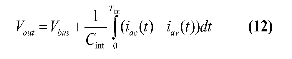
On peut écrire la relation (12) de manière équivalente, au premier ordre, c'est-à-dire en admettant que les courants iac et iav sont constants sur la durée d'intégration Tint : 
Comme le courant iav traversant le bolomètre de compensation 2011 est sensiblement égal au courant de mode commun traversant le bolomètre d'imagerie 1011, la différence entre la résistance électrique du bolomètre d'imagerie 1011 et la résistance du bolomètre de compensation 2011 associé, qui induit la différence de courant en entrée du circuit d'intégration 202, est alors essentiellement représentative de la variation ΔRac de la résistance électrique Rac du bolomètre d'imagerie 1011 induite par le rayonnement issu de la scène et incident sur celui-ci.Since the current i av across the 2011 compensating bolometer is substantially equal to the common mode current flowing through the
Les tensions Vout de la ligne en cours de lecture sont envoyées au circuit 60 pour un échantillonnage - blocage et multiplexage. Le signal brut de sortie NC associé à un bolomètre d'imagerie 1011 est donc, dans l'exemple illustré ici, la valeur échantillonnée de la tension Vout . Par souci de clarté afin de ne pas alourdir les notations, les valeurs analogiques seront par la suite employées dans les relations algébriques, étant entendu qu'en réalité, il s'agit plutôt des valeurs digitales fournies par un convertisseur analogique-numérique (ADC pour les anglo-saxons) qui sont utilisées. Selon ce raccourci, on a donc Vout = S ou Vout = NC. The voltages V out of the line being read are sent to the
Le ou les signaux de température du substrat produits par la ou les sondes de température 30 sont également insérés dans le flux de données en sortie du multiplexeur 60 selon des techniques connues.The substrate temperature signal (s) produced by the temperature sensor (s) 30 are also inserted into the output data stream of the
Une telle structure de détecteurs bolométriques est classique et ne sera pas expliquée plus en détail par la suite. Pour de plus amples informations, on pourra utilement se reporter par exemple au document
En se référant de nouveau à la
Un circuit de calcul 90 reçoit le flux d'images corrigées et détermine alors une température θ scène (ou toute grandeur d'intérêt en sortie en relation avec θ scène si l'application n'est pas strictement thermographique) du rayonnement infrarouge IR incident sur chaque bolomètre d'imagerie 1011 en fonction des signaux corrigés en sortie du circuit de calcul 70, de la responsivité Resp 809 du détecteur 10 par rapport à la température de la scène, conservée dans une unité de mémoire 80, ainsi que la table de gains 802. A
Une unité de calcul 100 est par ailleurs prévue pour la mise à jour des tables d'offsets 801 et de gains 802 et est raccordée à l'obturateur 50, au circuit de lecture 20, et à l'unité de mémoire 80. Pour son fonctionnement, l'unité de calcul 100 comporte une horloge interne 1001 ainsi qu'une mémoire 1002 pour stocker ses calculs intermédiaires. L'unité 100 est également adaptée pour recevoir des ordres de mise à jour 1003 de la part de l'utilisateur du détecteur.A
Bien évidemment, on comprendra que les unités 70, 80, 90, 100 puissent être mises en oeuvre dans un ou plusieurs microprocesseurs, l'accent ayant été mis dans l'exemple illustré sur les fonctions mises en oeuvre plutôt que sur le matériel qui pourrait être réellement utilisé.Of course, it will be understood that the
Il va à présent être décrit, en relation avec l'organigramme de la
Ce premier mode de réalisation s'applique plus généralement à tout type de détecteur mettant en oeuvre une estimation des valeurs des résistances des bolomètres d'imagerie 1011 ou de toutes grandeurs représentatives de celles-ci. Comme cela apparaîtra ci-dessous, la détermination d'une nouvelle table de gains est indépendante des paramètres particuliers du circuit de lecture.This first embodiment applies more generally to any type of detector implementing an estimate of the values of the resistances of the
Le procédé débute par une première phase 200 de calibration en usine visant à obtenir les données initiales permettant la mise en oeuvre ultérieure de la détermination d'une nouvelle table de gains selon la relation (10). The method begins with a
Plus particulièrement, la phase de calibration 200 débute par l'acquisition, en 2001, de deux tables de signaux bruts des bolomètres 1011 de la rétine 10, lorsque la caméra est disposée devant deux corps noirs portés aux températures uniformes T1 et T2, désignées respectivement par NCT1(i,j) et NCT2(i,j). Les tables NCT1(i,j) et NCT2(i,j) sont formées préférentiellement, comme cela est connu en soi, de la valeur moyenne de plusieurs trames acquises successivement, typiquement au moins dix trames successives, afin de filtrer les dispersions liées au bruit d'acquisition ou inhérent au détecteur.More particularly, the
En 2002, l'une des tables acquises, par exemple la table NCT1(i,j), est mémorisée en tant que table d'offsets initiale 801 dans la mémoire 80. La moyenne algébrique
De même, toujours en 2002, une table de gains initiale, ou « de référence » est calculée selon la relation 
La température du substrat pendant cette opération de calibration est également mémorisée en tant que température de référence Tref dans un espace 805 de la mémoire 80. Selon une forme plus élaborée d'estimation de cette grandeur au moyen de plusieurs sondes de température, une forme tabulée Tref(i,j) de la température de référence Tref est établie et mémorisée dans l'espace 805. The temperature of the substrate during this calibration operation is also stored as a reference temperature T ref in a
En 2003, la valeur des résistances Rac_ref (i,j) des bolomètres d'imagerie 1011 est calculée en fonction des paramètres du circuit de lecture 20 d'une manière connue en soi, par exemple au moyen d'une mise en oeuvre décrite dans le document 
L'unité de calcul 100 détermine alors une résistance électrique Rac_ref (i,j) du bolomètre d'imagerie 1011 en fonction de la tension Vout , par exemple en supposant que cette résistance est sensiblement constante pendant la durée d'intégration, auquel cas 
D'autres mises en oeuvre des mesures de Rac_ref (i,j) sont applicables, même en l'absence de l'interrupteur 2014, par exemple en appliquant successivement deux tensions VFID différentes, induisant deux polarisations Vac différentes, ou encore en imposant deux temps d'intégration Tint différents. On obtient alors une relation au premier ordre linéaire entre les grandeurs Vout obtenues et les résistances Rac_ref(i,j), dont on extrait une mesure des résistances Rac_ref (i,j), ou au moins une grandeur substantiellement proportionnelle, comme il sera décrit plus en détail ci-dessous.Other implementations of R ac_ref ( i , j ) measurements are applicable, even in the absence of the
En 2004, selon une variante préférée, l'énergie d'activation moyenne
Par exemple, dans le cas d'un matériau bolométrique constitué d'une variété particulière de silicium amorphe,
Selon une autre variante, l'énergie d'activation Earef (i,j) de chaque bolomètre d'imagerie est acquise de manière connue en soi, par exemple en mesurant les résistances Rac à deux températures uniformes de plan focal, typiquement distantes de quelques degrés C, et une table d'énergie d'activation de référence est mémorisée dans l'espace 807 de la mémoire 80. Dans le cas où plusieurs sondes de température sont disponibles, cette mesure préalable d'énergie d'activation est d'autant plus précise du fait que la différence de température imposée entre les deux mesures de Rac est mesurée ou modélisée en tout point de la rétine.According to another variant, the activation energy Ea ref ( i , j ) of each imaging bolometer is acquired in a manner known per se, for example by measuring the resistances R ac at two uniform focal plane temperatures, typically distant a few degrees C, and a reference activation energy table is stored in the
En 2006, le coefficient K des relations (8) et (9) est mémorisé dans un espace 808 de la mémoire 80. Par exemple, dans le cas d'une variété particulière de matériaux bolométriques constitués de silicium amorphe, K = 0,055 eV dans une large gamme de températures autour de 30 °C.In 2006, the coefficient K of the relations (8) and (9) is stored in a
Le coefficient K est par exemple obtenu en extrayant, préalablement à la séquence d'opérations exposée ici, le coefficient directeur des points expérimentaux reliant l'énergie d'activation Ea au logarithme des résistances, mesurés sur un composant dont les pixels ont été localement modifiés par éclairement intense, et donc pour lesquels les matériaux sensibles constituant les résistances Rac (i,j) ont plus ou moins été modifiés.The coefficient K is for example obtained by extracting, before the sequence of operations described here, the directing coefficient of the experimental points connecting the activation energy Ea to the logarithm of the resistances, measured on a component whose pixels have been locally modified. by intense illumination, and therefore for which the sensitive materials constituting the resistors R ac ( i , j ) have more or less modified.
L'extraction des valeurs du coefficient K peut, en complément éventuel, être étendue sur la plage complète de températures d'intérêt, de manière à obtenir la courbe comportementale K(TPF) en fonction de la température du plan focal. Cette relation comportementale empirique peut ensuite être exprimée sous forme analytique, par exemple polynomiale. Les divers coefficients nécessaires à la mise en oeuvre de l'invention sont dans ce cas également stockés dans l'espace 808. The extraction of the values of the coefficient K may, in addition possibly, be extended over the full range of temperatures of interest, so as to obtain the behavioral curve K (TPF) as a function of the temperature of the focal plane. This empirical behavioral relationship can then be expressed in analytical form, for example polynomial. The various coefficients necessary for the implementation of the invention are in this case also stored in the
Les inventeurs ont cependant constaté que le paramètre K(TPF) n'est pas critique en termes de qualité de correction, à au moins +/- 20% près, même lorsque la température du détecteur varie dans de très larges proportions, et/ou que le bolomètre considéré dérive par exemple de +/- 10% en résistivité (à température constante), ce qui représente un cas vraiment extrême.The inventors have however found that the parameter K (TPF) is not critical in terms of correction quality, at least +/- 20%, even when the detector temperature varies in very large proportions, and / or that the bolometer considered derives, for example, from +/- 10% in resistivity (at constant temperature), which represents a really extreme case.
Il est entendu que les valeurs proposées pour les paramètres
Enfin, en 2007, la responsivité moyenne 
Comme précisé précédemment, la responsivité est étalonnée sur l'ensemble de la gamme de températures opérationnelles de la caméra, de sorte qu'on établit et mémorise quelques points de la courbe
Le procédé se poursuit alors par une deuxième phase 300 mise en oeuvre alors que le détecteur est en service. La deuxième phase 300 comprend une étape 3001 de mise en marche du détecteur qui ouvre l'obturateur 50 et déclenche un processus 3002 d'acquisition d'un flux vidéo de la scène observée.The process then continues with a
Le processus 3002 comporte l'acquisition, en 30021, d'une table de signaux bruts S(i,j) par le circuit de lecture 20, suivi, en 30022, d'une correction « deux points » de la table S(i,j) par le circuit de calcul 70 selon la relation : 
Le processus 3002 se poursuit par le calcul, en 30023, d'une image thermométrique (ou plus généralement « d'intérêt ») θ(i,j) par le circuit de calcul 90 à partir de la table de signaux corrigés Scorr(i,j) délivrée par le circuit de calcul 70 selon une relation du type θ scene (i,j) = f(Scorr (i,j),
Enfin, l'étape 30023 reboucle sur l'étape 30021 pour l'acquisition et le traitement d'une nouvelle table de signaux bruts.Finally, step 30023 loops back to step 30021 for acquiring and processing a new raw signal table.
Parallèlement au processus 3002 d'acquisition du flux vidéo, l'étape 3001 de mise en marche déclenche un processus 3003 de mise à jour de la table d'offsets 801, de la table de gains 802 et de la responsivité moyenne 809 mise en oeuvre par l'unité de calcul 100. In parallel with the
Le processus 3003 de mise à jour comporte une première étape 30031 de test de l'occurrence d'une condition de mise à jour de ces données. Par exemple, l'unité de calcul 100 teste si un ordre a été émis par l'utilisateur pour procéder à une telle mise à jour, et/ou si la durée écoulée depuis la dernière mise à jour est supérieure à une durée de seuil prédéterminée, et/ou si la température du substrat délivrée par le capteur de température 30 est différente de la température du substrat lors de la dernière mise à jour de plus d'une valeur de seuil prédéterminé. L'unité de calcul peut également mettre en oeuvre un algorithme de traitement pour déterminer si la rétine 10 a subi une illumination intense signifiant une modification des caractéristiques intrinsèques des bolomètres ainsi surexposés, et donc une possible dérive de ceux-ci.The
Si la température du substrat est tabulée pour chaque bolomètre, selon une forme plus élaborée d'estimation de cette grandeur au moyen du signal fourni par plusieurs sondes, l'occurrence d'une condition de mise à jour relative à la température peut prendre en compte plusieurs de ces signaux, ou combinaisons de ces signaux entre eux ou avec d'autres paramètres réputés utiles ou pertinents dans ce contexte d'intérêt de prise en compte des variations globales ou locales de température du plan focal.If the temperature of the substrate is tabulated for each bolometer, according to a more elaborate form of estimation of this quantity by means of the signal supplied by several probes, the occurrence of a temperature update condition may take into account several of these signals, or combinations of these signals with each other or with other parameters deemed useful or relevant in this context of interest taking into account global or local variations of focal plane temperature.
Si l'une des conditions de mise à jour est satisfaite, le processus 3003 se poursuit par la fermeture, en 30032, de l'obturateur 50. Si la caméra ne comporte pas d'obturateur, le système (et/ou l'utilisateur) n'engagera l'étape 30032 qu'après satisfaction d'une condition d'uniformité de scène suffisante, ou activera tout système destiné à uniformiser autant que possible l'image perçue sur la rétine.If one of the updating conditions is satisfied, the
En 30033, une table de signaux bruts NCshut (i,j)est alors mémorisée dans la mémoire 1002 de l'unité 100, cette table étant de préférence formée de la moyenne de plusieurs trames successives, par exemple dix. La température du substrat Tshut délivrée par le capteur 30 à l'instant d'acquisition de la table NCshut (i,j) et la moyenne algébrique
Le processus se poursuit, en 30034, par le calcul par l'unité 100 des valeurs de résistance Rac_shut(i,j) selon une méthode par exemple proposée dans le document
De même, toujours en 30034, les valeurs de résistance Rac_ref (i,j)@Tshut sont estimées en fonction des valeurs de résistance Rac_ref(i,j), de la ou des énergies d'activation Earef et de la température Tref mémorisée dans la mémoire 80, ainsi que de la température Tshut mémorisée dans l'unité 100. Cette estimation est par exemple mise en oeuvre en utilisant la relation (11) directement sous cette forme, ou à tout le moins une forme numérique ou linéarisée de celle-ci. Il est entendu que Tref et Tshut peuvent aussi être tabulées.Similarly, again at 30034, the resistance values R ac_ref ( i , j ) @ T shut are estimated as a function of the resistance values R ac_ref (i , j) , the activation energy or energies Ea ref and the temperature T ref stored in the
Les valeurs de résistance Rac_ref (i,j)@Tshut et Rac_shut(i,j) sont mémorisées dans des tables correspondantes dans la mémoire 1002 de l'unité 100. The resistance values R ac_ref ( i , j ) @ T shut and R ac_shut (i , j) are stored in corresponding tables in the
Ensuite, en 30035, les facteurs de correction au premier ordre 
De même, les facteurs de correction au second ordre β(i,j) sont calculés et mémorisés par l'unité 100, par exemple en utilisant la relation β(i,j) de la relation (10) directement sous cette forme, ou de manière avantageuse, notamment pour une plus grande rapidité de calcul, en mettant en oeuvre une forme linéarisée au premier ordre de cette relation selon l'expression : 
En 30036, une nouvelle table de gains est alors calculée par l'unité 100. In 30036, a new pay table is then calculated by
La nouvelle table de gains est alors calculée selon la relation : 
Toujours en 30036, optionnellement, l'unité 100 calcule une nouvelle responsivité moyenne
Enfin, la mise à jour 3003 se termine, en 30037, par la mise à jour des données de la mémoire 80, à savoir :
- ■ le remplacement des valeurs courantes de la table d'offsets NC 801(i,j) et de sa moyenne mémorisée
NC 801 dans l'espace mémoire 801 respectivement par la table de valeurs brutes NCshut (i,j) et la moyenne algébriqueNCshut de celle-ci; - ■ optionnellement, le remplacement de la valeur de la responsivité moyenne mémorisée dans l'espace mémoire 809 par la responsivité moyenne nouvellement calculée
Re spshut ; - ■ la mémorisation de données utilisées pour
le test 30031 de déclenchement de la mise à jour, notamment la température Tshut et des données d'horodatage Hshut de l'instant de la mise à jour, par exemple dans la mémoire 80 ; - ■ l'ouverture de l'obturateur 50; et
- ■ le rebouclage sur l'étape de
test 30031 pour la scrutation de l'occurrence des conditions de déclenchement de la mise à jour.
- ■ replacing the current values of the NC 801 ( i , j ) offsets table and its stored average
NC 801 in thememory space 801 respectively by the table of raw values NC shut ( i , j ) and the average algebraicNC shut of it; - Optionally, the replacement of the value of the average responsivity stored in the
memory space 809 by the newly calculated average responsivityRe sp shut ; - Storage of data used for the
test 30031 for triggering the update, in particular the temperature T shut and timestamp data H shut of the instant of the update, for example in thememory 80; - ■ the opening of the
shutter 50; and - ■ the loopback on the
test step 30031 for the polling of the occurrence of the conditions for triggering the update.
Il s'entend que s'il est mis en oeuvre une pluralité de sondes de température en divers points du substrat, une forme tabulée des paramètres Tref et Tshut sera typiquement utilisée partout où ces paramètres apparaissent, comme il a été indiqué.It is understood that if a plurality of temperature probes are implemented at various points on the substrate, a tabulated form of the parameters T ref and T shut will typically be used wherever these parameters appear, as indicated.
Comme dit précédemment, le premier mode de réalisation de l'invention s'applique à des détecteurs qui permettent de déterminer la valeur des résistances des bolomètres. Cette détermination peut consister en un calcul réalisé en fonction des signaux bruts délivrés en sortie du circuit de lecture ou par tout autre moyen. Notamment, il est décrit un détecteur comportant des interrupteurs 2014 dans les circuits de compensation 201 permettant la mesure de tensions Vout associées uniquement aux bolomètres d'imagerie 1011. D'autres architectures de mesure de résistances sont possibles. En variante, plutôt que de réduire la durée d'intégration, la valeur de la capacité C int des condensateurs 2022 est augmentée de manière à ce que ceux-ci ne saturent pas lors d'une intégration de durée T int utilisée lors du fonctionnement normal du détecteur. Par exemple, chaque intégrateur 202 comporte deux condensateurs, un premier étant sélectionné par le circuit de cadencement 203 lors de la lecture de la matrice d'imagerie 10, et le second étant sélectionné lors de la mesure de la résistance des bolomètres d'imagerie 1011. As said above, the first embodiment of the invention applies to detectors which make it possible to determine the value of the resistances of the bolometers. This determination may consist of a calculation performed as a function of the raw signals delivered at the output of the read circuit or by any other means. In particular, there is described a
En variante, l'architecture décrite dans le document
Il convient cependant de préciser qu'il n'y a pas besoin d'estimer les résistances Rac_shut(i,j) proprement dites pour mettre en oeuvre le premier mode de réalisation. En effet, les tables de gains Gshut (i,j) sont invariantes lorsque l'échelle des rapports de « Rac » introduits dans les relations précédentes est spatialement uniforme. L'usage de n'importe quel protocole de « mesure » des résistances produit le résultat attendu, pourvu que la proportionnalité du résultat de ce protocole par rapport aux résistances Rac soit au moins approximative, et que ledit protocole soit spatialement reproductible pour tous les bolomètres de la rétine.It should be noted, however, that there is no need to estimate the resistances R ac_shut (i , j) proper to implement the first embodiment. Indeed, the gain tables G shut ( i , j ) are invariant when the scale of the ratios of " R ac " introduced in the previous relations is spatially uniform. The use of any protocol for "measuring" the resistances produces the expected result, provided that the proportionality of the result of this protocol with respect to the resistances R ac is at least approximately, and that said protocol is spatially reproducible for all bolometers of the retina.
Ces conditions sont satisfaites par exemple selon les enseignements du document
Le détecteur décrit notamment en relation avec la
On comprendra que le premier mode de réalisation s'applique également à des détecteurs ayant des circuiteries de polarisation différentes, par exemple des circuits de polarisation en courant ou encore des circuits de compensation de mode commun différents. Le premier mode de réalisation s'applique bien entendu également à des détecteurs régulés en température, auquel cas la mesure de la température du substrat est optionnelle, la température Tshut étant identique à la température Tref objet de la régulation de température. Les relations précédentes sont alors simplifiées en conséquence, et notamment ne comprennent pas de rapport de température et ne nécessitent pas d'estimer les valeurs Rac_ref (i,j)@Tshut qui sont par définition égales aux valeurs Rac_ref (i,j).It will be understood that the first embodiment also applies to detectors having different polarization circuitry, for example current bias circuits or else different common mode compensation circuits. The first embodiment of course also applies to temperature-regulated detectors, in which case the measurement of the temperature of the substrate is optional, the temperature T shut being identical to the temperature T ref subject of the temperature control. The preceding relations are then simplified accordingly, and in particular do not include a temperature ratio and do not require the estimation of the values R ac_ref ( i , j ) @ T shut which are by definition equal to the values R ac_ref ( i , j ).
L'invention s'applique également aux détecteurs qui ne comprennent pas de moyens logiciels et/ou matériels de détermination des valeurs des résistances des bolomètres, ce qui permet d'appliquer l'invention à des détecteurs de l'état de la technique sans modification du détecteur lui-même ni des matériels et logiciels de proximité par exemple de pilotage et formatage des signaux bruts.The invention also applies to detectors which do not include software and / or hardware means for determining the values of the bolometer resistances, which makes it possible to apply the invention to detectors of the state of the art without modification. the detector itself or hardware and software proximity for example piloting and formatting raw signals.
Le second mode de réalisation de l'invention est à présent décrit en relation avec l'organigramme de la
Le problème du second mode de réalisation, par rapport au premier mode exposé précédemment, est posé par l'absence en service de mesure directe, par exemple substantiellement proportionnelle, ou indirecte, par exemple substantiellement linéaire, de résistance. En effet, cette mesure permet de quantifier directement, pour chaque bolomètre d'imagerie 1011, la quantité de variation de résistance attribuable à une véritable dérive, c'est-à-dire à laquelle est associée une variation de Ea. Dans le premier mode de réalisation décrit précédemment, la conséquence d'une variation de température de la caméra, qui n'implique aucune variation significative de l'énergie d'activation, est ainsi différenciée d'une variation de résistivité intrinsèque d'un bolomètre 1011 particulier, à laquelle correspond une variation calculable d'énergie d'activation grâce aux relations (8) ou (9). The problem of the second embodiment, with respect to the first mode explained above, is posed by the absence in the direct measurement service, for example substantially proportional, or indirect, for example substantially linear, of resistance. Indeed, this measurement makes it possible to directly quantify, for each
Il est maintenant nécessaire, en l'absence de grandeur directement utilisable pour estimer chaque résistance, de former pour chaque bolomètre 1011 de la rétine 10 une grandeur sur laquelle appliquer de manière pertinente une correction au second ordre.It is now necessary, in the absence of a directly usable quantity to estimate each resistance, to form for each
Tout d'abord, on note que la valeur du terme ΔNC(i,j) = NCshut (i,j)-NCref (i,j), entre un instant courant de température de substrat Tshut et un instant antérieur de température de substrat Tref , dépend pour une partie de la dérive des bolomètres 1011 et comporte donc des informations concernant celle-ci. Le second mode de réalisation se propose donc d'extraire du terme ΔNC(i,j) l'essentiel de la composante liée à la dérive intrinsèque, c'est-à-dire hors variation de température, des bolomètres 1011. Firstly, it is noted that the value of the term Δ NC ( i , j) = NC shut ( i , j ) -NC ref ( i , j ), between a current instant of substrate temperature T shut and a previous instant substrate temperature T ref , depends for a part of
En se référant à la relation (13), le terme ΔNC(i,j) se formule au premier ordre selon la relation : 
Les écarts 
La mise en oeuvre de plusieurs sondes de température donne l'information nécessaire si besoin pour corriger chaque écart associé aux membres 
La relation (22) se simplifie donc en la relation : 
Ensuite, pour isoler la portion du terme ΔNC(i,j) liée à la dérive des bolomètres, le second mode de réalisation repose sur la comparaison de ce terme avec la moyenne Δ 
Selon une première variante, on observe qu'en général, seule une petite fraction des bolomètres d'imagerie 1011 est concernée par le phénomène de dérive à corriger. C'est typiquement le cas des rétines de grand format après observation du soleil sur une durée limitée (par exemple quelques minutes), car au pire, quelques % du nombre total des bolomètres 1011 sont touchés par la dérive. Dans ce cas, on constate que Δ
Selon une seconde variante qui estime de manière plus précise Δ
Par exemple, une sélection spatiale gérée par logiciel des bolomètres d'imagerie 1011 associés aux éléments de la table de gains ayant subi une modification importante lors de la (ou des) dernière(s) mises à jour de cette table est mise en oeuvre. Les bolomètres 1011 qui ont véritablement dérivé sont ainsi identifiés pour la mise à jour en cours. La valeur Δ
Par ailleurs, la grandeur Δ 
![]()
![]()
![]()
![]()
En combinant les relations (20) et (21), il est alors obtenu au premier ordre : 
Or, selon le cas général, la dispersion des résistances Rac_ref (i,j) est modérée, notamment parce que ces valeurs correspondent aux résistances des bolomètres en sortie d'usine alors qu'ils n'ont pas subi de dérive. Ainsi donc, le terme 
Une réorganisation de l'équation (22) sans ce second terme conduit alors à la relation suivante : 
![]()

![]()
Le rapport de la relation (23) représente une variation relative entre les résistances des bolomètres 1011 non touchés par une dérive (représentés par le terme moyen au numérateur) et les résistances des bolomètres qui ont dérivé (représentés par la table du dénominateur).The ratio of the relation (23) represents a relative variation between the resistances of the non-drifting bolometers 1011 (represented by the average term in the numerator) and the resistances of the drifting bolometers (represented by the denominator table).
Le facteur α(i,j) peut alors s'exprimer ainsi en exploitant la relation (24) : 
En reprenant la relation (23) dans la relation précédente, on obtient : 
Le facteur β(i,j) est obtenu en combinant les relations (10), (23) et (24) selon l'expression : 
Comme par ailleurs les inventeurs ont constaté que dans le cas général le second terme de l'argument logarithmique du dénominateur est très inférieur à 1, la relation (26) peut se réécrire au premier ordre selon la relation : 
Ainsi donc, les relations (10) se réécrivent selon les relations : 
Une bonne approximation de la table de gains normalisée simplifiant les calculs mis en oeuvre est obtenue selon l'expression suivante : 
Le facteur de correction de responsivité moyenne, utile pour maintenir avantageusement la calibration thermographique à partir d'une seule acquisition en usine, est dans ce cas très bien approximé par N = α.β. En outre, s'il n'est pas appliqué de processus de discrimination des éléments réputés avoir ou non dérivé, le terme Δ
Les relations (28) et (29) reprennent donc toujours la table initiale de gains, qui est corrigée au niveau dispersif par l'évolution « au premier ordre » des résistances (termes α) et « au second ordre » selon l'invention par l'évolution du TCR (termes β). Enfin, tout comme selon le premier mode de réalisation, l'évolution de responsivité moyenne est accessible via le facteur de normalisation N disponible à l'issue de la séquence de calcul de la table de gains corrigée. Il est enfin entendu que dans les expressions précédentes, le paramètre K peut être exprimé en fonction de Tshut si besoin, et les températures Tref et Tshut tabulées si estimé utile pour la précision des corrections.The relations (28) and (29) thus always take up the initial table of gains, which is corrected at the dispersive level by the "first order" evolution of the resistances (terms α) and "second order" according to the invention by the evolution of the TCR (terms β). Finally, as in the first embodiment, the evolution of average responsivity is accessible via the normalization factor N available at the end of the calculation sequence of the corrected gain table. It is finally understood that in the preceding expressions, the parameter K can be expressed as a function of T shut if necessary, and the temperatures T ref and T shut tabulated if estimated useful for the accuracy of the corrections.
La calibration thermographique peut cependant être obtenue comme habituellement avec une série initiale d'acquisitions en usine de la responsivité moyenne à diverses températures. Dans ce cas il n'est pas besoin de former ni de conserver en mémoire le facteur de normalisation N ni ses composantes.Thermographic calibration can however be obtained as usual with an initial series of factory acquisitions of average responsivity at various temperatures. In this case, it is not necessary to form and store in memory the normalization factor N and its components.
On notera à la lecture de la relation (28) ou (29), qu'il convient selon ce second mode de réalisation de disposer de l'estimation de la valeur moyenne des résistances
Il va à présent être décrit plus en détail un exemple de réalisation du second mode de réalisation en relation avec la
Le second mode de réalisation débute par une phase de calibration en usine 400 comportant les étapes 2001 à 2007 précédemment décrites. On notera concernant les valeurs de résistance Rac_ref (i,j) des bolomètres d'imagerie 1011 qu'on dispose en usine des moyens nécessaires pour obtenir à l'étape 2003 une estimation de leur valeur moyenne
La phase de calibration comporte en outre une étape 4008 de mémorisation des paramètres du circuit de lecture 20, par exemple dans un espace mémoire supplémentaire de la mémoire 80, à savoir la valeur Tint de la durée d'intégration, la valeur Cint de la capacité d'intégration 2022, et la valeur Vac de la tension de polarisation des bolomètres d'imagerie 1011. The calibration phase further comprises a
Le procédé se poursuit alors par une deuxième phase 500 mise en oeuvre alors que le détecteur est en service. Cette deuxième phase comporte l'étape 3001 et le processus 3002 décrits précédemment, ainsi qu'un processus de mise à jour 5003 des tables de gains 803 et d'offsets 801 et de la responsivité moyenne 809. The process then continues with a
Le processus de mise à jour 5003 comporte les étapes de test 30031, de fermeture de l'obturateur 30032 et d'acquisition de la table de signaux bruts 30033, décrites précédemment.The
Le processus de mise à jour 5003 se poursuit par une étape 50034 de détermination de la table ΔNC(i,j) = NCshut (i,j)-NCref (i,j) et de la moyenne algébrique Δ
Toujours en 50034, la table D(i,j) = ΔNC(i,j) - Δ
De manière alternative plus précise, ce processus est enrichi par un sous-processus de détermination spatiale des résistances qui n'ont pas dérivé. Ce sous-processus exploite par exemple une comparaison des termes de la ou des dernière(s) table(s) de gains précédemment établies lors des itérations précédentes de mise à jour de la table de gains, comme il a été évoqué précédemment. La moyenne Δ
Ensuite, en 50035, les facteurs de correction au premier ordre α(i,j) et les facteurs de correction au second ordre β(i,j) sont calculés et mémorisés par l'unité 100. Optionnellement, l'unité 100 forme également les moyennes α et β si une correction « deux points » utilisant une table de gains normalisée approximée selon la relation (29) est mise en oeuvre.Then, in 50035, the first order correction factors α ( i , j ) and the second order correction factors β ( i , j ) are calculated and stored by the
En 50036, une nouvelle table de gains est alors calculée par l'unité 100. Selon une première variante, la correction « deux points » est mise en oeuvre en utilisant une table de gains « exactement normalisée » calculée selon la relation (28), et l'unité 100 calcule une nouvelle table de gains selon cette relation. Selon une deuxième variante, la correction « deux points » est mise en oeuvre en utilisant une table de gains approximativement normalisée selon la relation (29), et l'unité 100 calcule une nouvelle table de gains selon cette relation.In 50036, a new pay table is then calculated by the
Toujours en 50036, optionnellement, l'unité 100 calcule une nouvelle responsivité moyenne
Le procédé se poursuit alors par l'étape 30037 de mise à jour des données de la mémoire 80 précédemment décrite.The method then continues with the
Il n'est utilisé pour simplification des expressions qu'une température mesurée en un point du substrat. S'il est mis en oeuvre une pluralité de sondes de température en divers points du substrat, une forme tabulée des paramètres Tref et Tshut sera typiquement utilisée partout où ces paramètres apparaissent. De même, la définition des conditions de mise à jour de la table de gains dépendantes de la température plan focal est basée sur l'exploitation d'un seul, de plusieurs, ou d'une combinaison de ces signaux de température plan focal entre eux ou avec d'autres paramètres.It is used to simplify expressions only a temperature measured at a point of the substrate. If a plurality of temperature probes are implemented at various points on the substrate, a tabulated form of the parameters T ref and T shut will typically be used wherever these parameters occur. Similarly, the definition of the update conditions of the focal plane temperature dependent gain table is based on the exploitation of one, more, or a combination of these focal plane temperature signals between them. or with other parameters.
Dans les premier et second modes de réalisation précédemment décrits, le calcul d'une nouvelle table de gains a été présenté sous une succession d'étapes élémentaires de calcul pour des raisons de clarté. Bien entendu, la nouvelle table de gains peut être calculée en une seule étape ou des étapes élémentaires peuvent être regroupées en une seule étape.In the first and second embodiments described above, the calculation of a new earnings table has been presented under a succession of elementary calculation steps for the sake of clarity. Of course, the new pay table can be calculated in one step or elementary steps can be grouped in one step.
De même, ces modes présentent l'avantage de pouvoir utiliser une seule et unique table de gains pour la correction « deux points » et ceci pour tout le domaine de fonctionnement en température du détecteur. Si l'application le nécessite, plusieurs tables de gains peuvent être utilisées et mises à jour d'une manière analogue à celle décrite ci-dessus.In the same way, these modes have the advantage of being able to use a single table of gains for the correction "two points" and this for all the domain of operation in temperature of the detector. If the application requires it, several pay tables can be used and updated in a manner similar to that described above.
Il a été décrit des modes de réalisation dans lequel la table d'offsets est également mise à jour. La mise à jour de la table de gains nécessitant l'acquisition d'une table de signaux bruts correspondant à l'obturateur, cette table est avantageusement acquise pour mettre également à jour la table d'offsets. Toutefois, on comprendra que cette mise à jour de la table d'offsets, bien que privilégiée, est optionnelle. De même, la mise à jour de la table d'offsets par un simple remplacement de celle-ci n'est qu'une possibilité parmi d'autres. D'autres types de mise à jour de la table d'offsets peuvent être mis en oeuvre.Embodiments have been described in which the offsets table is also updated. The update of the pay table requiring the acquisition of a raw signal table corresponding to the shutter, this table is advantageously acquired to also update the offsets table. However, it will be understood that this The day of the offsets table, although privileged, is optional. Similarly, updating the offsets table by simply replacing it is only one possibility among others. Other types of update of the offsets table can be implemented.
Il a été décrit des modes de réalisation utilisant un obturateur formant une scène sensiblement uniforme en rayonnement lorsqu'il est fermé. L'utilisation d'un obturateur permet non seulement l'obtention d'une telle scène indépendamment de l'environnement du détecteur, mais permet également d'obtenir une scène de température proche, du point de vue des bolomètres, de la température de ceux-ci et du substrat. En variante de chacun des modes de réalisation décrits précédemment, il n'est pas utilisé d'obturateur, et les signaux de lecture utilisés pour réaliser la correction de la table de gain sont ceux correspondants à une scène observée par le détecteur. Il convient cependant que cette scène soit sensiblement uniforme, ou rendue uniforme au niveau du plan focal par exemple au moyen d'une défocalisation de l'image, et de préférence à une température de l'ordre de celle du plan focal, typiquement distante de ladite température de moins de 20 °C.Embodiments have been described using a shutter forming a substantially uniform radiation scene when closed. The use of a shutter not only makes it possible to obtain such a scene independently of the environment of the detector, but also makes it possible to obtain a temperature scene close to the point of view of the bolometers, the temperature of those and the substrate. As a variant of each of the embodiments described above, no shutter is used, and the read signals used to perform the correction of the gain table are those corresponding to a scene observed by the detector. However, this scene should be substantially uniform, or rendered uniform at the focal plane, for example by means of a defocusing of the image, and preferably at a temperature of the order of that of the focal plane, typically distant from said temperature of less than 20 ° C.
La
Il résulte de ce qui précède les nombreux avantages de l'invention, parmi lesquels :
- ■ une correction efficace des dérives des bolomètres liées à un changement intrinsèque de leur caractéristique, notamment suite à de fortes illuminations, et ce, sans faire appel à des procédures de calibration nécessitant un retour chez le constructeur ;
- ■ la possibilité de n'utiliser qu'une seule et même table de gains pour tout le domaine de fonctionnement en température du détecteur ;
- ■ une correction efficace des dérives des bolomètres, globales (affectant tous les pixels simultanément) ou locales (images dites rémanentes), que le détecteur soit ou non régulé en température ;
- ■ la faculté d'utiliser le facteur de normalisation N de la table de gains corrigée pour la correction de la calibration thermométrique de responsivité, même avec une simplification de la calibration en usine de responsivité moyenne à une seule température plan focal de référence ;
- ■ la possibilité de mettre en oeuvre la correction des dérives locales, y compris sur des détecteurs qui ne mettent pas en oeuvre d'estimation des valeurs des résistances. Le procédé s'applique donc à ce type de détecteur déjà en service, au moyen de la mise à jour du processus de correction selon la méthode de l'invention ;
- ■ en outre selon l'invention, les contributions aux variations de responsivité moyenne dues respectivement à la dérive globale ou locale des caractéristiques intrinsèques des bolomètres, et aux évolutions (dérive) de température du plan focal (pour les caméras à plan focal non régulées en température) sont connues indépendamment. Il est ainsi possible d'exploiter ces contributions indépendamment de manière avantageuse, par exemple pour fournir des informations particulières utiles à l'utilisateur de la caméra, déclencher des processus de mémorisation (logging) de la vie du système, déclencher des protocoles opératoires automatiques hors du champ de l'invention, autoriser des traitements de données particuliers également au-delà du champ de l'invention. On peut ainsi former des statistiques de datation, récurrence, intensité, densité et localisation spatiale des épisodes d'irradiation intense.
- ■ effective correction of drifts of bolometers related to an intrinsic change in their characteristic, especially following strong illuminations, and without using calibration procedures requiring return to the manufacturer;
- ■ the possibility of using only one and the same table of gains for the whole temperature operating domain of the detector;
- ■ effective correction of drifts bolometers, global (affecting all pixels simultaneously) or local (so-called persistent images), regardless of whether the detector is temperature controlled;
- ■ the ability to use the normalization factor N of the corrected gain table for the correction of the responsivity thermometric calibration, even with a simplification of the average responsivity factory calibration at a single reference focal plane temperature;
- ■ the possibility of implementing the correction of local drifts, including detectors that do not implement an estimate of the values of the resistors. The method therefore applies to this type of detector already in service, by means of updating the correction process according to the method of the invention;
- In addition according to the invention, the contributions to the variations of average responsivity due respectively to the global or local drift of the intrinsic characteristics of the bolometers, and to the changes (drift) of the focal plane temperature (for the non-regulated focal plane cameras in temperature) are known independently. It is thus possible to exploit these contributions independently in an advantageous manner, for example to provide particular information useful to the user of the camera, to trigger logging processes of the life of the system, to trigger automatic operating protocols out of of the scope of the invention, allow special data processing also beyond the scope of the invention. It is thus possible to form dating, recurrence, intensity, density and spatial location statistics of intense irradiation episodes.
On notera également que les relations (8) et (9) permettant de déduire une variation d'énergie d'activation d'un bolomètre résistif en fonction d'une variation de sa résistance électrique peuvent faire l'objet de nombreuses autres applications.It will also be noted that the relationships (8) and (9) making it possible to deduce an activation energy variation of a resistive bolometer as a function of a variation in its electrical resistance can be the subject of many other applications.
Elles peuvent par exemple être utilisées dans des simulateurs numériques pour modéliser l'évolution de l'énergie d'activation des bolomètres à partir de données expérimentales.For example, they can be used in digital simulators to model the evolution of bolometer activation energy from experimental data.
Ces relations peuvent également faire l'objet de dispositifs de diagnostic pour déterminer le comportement de bolomètres pour une température donnée. En effet, en connaissant la résistance électrique et l'énergie d'activation initiales d'un bolomètre pour une température donnée, et en mesurant la résistance courante du bolomètre pour cette même température, il est possible de détecter de manière simple si des bolomètres ont fortement dérivé, par exemple suite à une irradiation intense, en calculant l'énergie d'activation courante à l'aide des relations (8) et (9) et en comparant la valeur calculée à la valeur initiale de l'énergie d'activation.
Il est ainsi possible de détecter les bolomètres ayant dérivé dans une rétine afin par exemple d'opérer un fenêtrage particulier dans les trames issues de cette rétine. Cette détection des bolomètres ayant dérivé peut ainsi avantageusement être mise en oeuvre dans le dispositif de correction des phénomènes de rémanence décrit dans le document
It is thus possible to detect bolometers having derived in a retina, for example to operate a particular windowing in the frames resulting from this retina. This detection of the bolometers having derived can thus advantageously be implemented in the device for correcting the phenomena of remanence described in the document
Claims (16)


expressions dans lesquelles :
expressions in which:


expression dans laquelle :
expression in which:

expression dans laquelle :
expression in which:
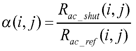

expression dans laquelle :
expression in which:

où :
or :
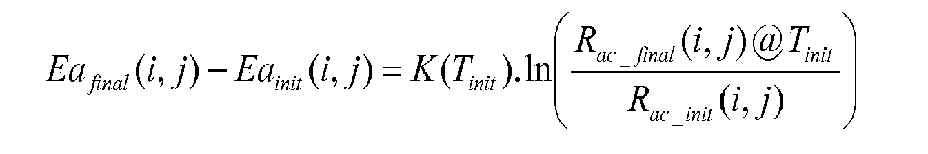
expression dans laquelle :
expression in which:
Applications Claiming Priority (1)
| Application Number | Priority Date | Filing Date | Title |
|---|---|---|---|
| FR1251592A FR2987210B1 (en) | 2012-02-22 | 2012-02-22 | METHOD FOR CORRECTING THE DERIVATIVE OF AN INFRARED RADIATION DETECTOR COMPRISING A RESISTIVE IMAGING BOLOMETER MATRIX AND DEVICE USING SUCH A METHOD |
Publications (3)
| Publication Number | Publication Date |
|---|---|
| EP2632150A2 true EP2632150A2 (en) | 2013-08-28 |
| EP2632150A3 EP2632150A3 (en) | 2016-02-17 |
| EP2632150B1 EP2632150B1 (en) | 2019-05-08 |
Family
ID=46963769
Family Applications (1)
| Application Number | Title | Priority Date | Filing Date |
|---|---|---|---|
| EP13155702.7A Active EP2632150B1 (en) | 2012-02-22 | 2013-02-19 | Method for correcting the drift of an infrared radiation detector comprising an array of resistive imaging bolometers and device implementing such a method |
Country Status (5)
| Country | Link |
|---|---|
| US (1) | US9442020B2 (en) |
| EP (1) | EP2632150B1 (en) |
| CN (1) | CN103292908B (en) |
| FR (1) | FR2987210B1 (en) |
| IL (1) | IL224627A (en) |
Cited By (4)
| Publication number | Priority date | Publication date | Assignee | Title |
|---|---|---|---|---|
| EP2940991A1 (en) * | 2014-04-30 | 2015-11-04 | Ulis | Method for processing an infrared image for correction of non-uniformities |
| EP3062074A1 (en) * | 2015-02-27 | 2016-08-31 | Axis AB | Method and system for detecting a need for recalibrating a microbolometer, and method and system for recalibrating a microbolometer |
| WO2020221773A1 (en) * | 2019-04-30 | 2020-11-05 | Lynred | Method and device for removing remanence in an infrared image of a changing scene |
| US11875484B2 (en) | 2019-04-30 | 2024-01-16 | Lynred | Method and device for removing remanence in an infrared image of a static scene |
Families Citing this family (18)
| Publication number | Priority date | Publication date | Assignee | Title |
|---|---|---|---|---|
| DE102013017911A1 (en) | 2013-10-29 | 2015-05-21 | Julian Pablo Berz | Method and device for improving and stabilizing the accuracy of infrared cameras for real-time temperature measurement |
| WO2016028755A1 (en) * | 2014-08-20 | 2016-02-25 | Seek Thermal, Inc. | Adaptive adjustment of operating bias of an imaging system |
| US9797942B2 (en) * | 2014-08-28 | 2017-10-24 | Seek Thermal, Inc. | Radiometric test and configuration of an infrared focal plane array at wafer probe |
| US10025685B2 (en) * | 2015-03-27 | 2018-07-17 | Intel Corporation | Impedance compensation based on detecting sensor data |
| RU2603338C1 (en) * | 2015-09-03 | 2016-11-27 | Российская Федерация, от имени которой выступает Государственная корпорация по атомной энергии "Росатом" (Госкорпорация "Росатом") | Method of calibrating sensor containing heat-sensitive element |
| CN106092326B (en) * | 2016-07-08 | 2023-04-07 | 无锡艾立德智能科技有限公司 | Compensation circuit and compensation method of infrared focal plane detector reading circuit |
| US10511793B2 (en) | 2017-06-05 | 2019-12-17 | Adasky, Ltd. | Techniques for correcting fixed pattern noise in shutterless FIR cameras |
| US10929955B2 (en) | 2017-06-05 | 2021-02-23 | Adasky, Ltd. | Scene-based nonuniformity correction using a convolutional recurrent neural network |
| US10699386B2 (en) | 2017-06-05 | 2020-06-30 | Adasky, Ltd. | Techniques for scene-based nonuniformity correction in shutterless FIR cameras |
| EP3621850B1 (en) * | 2017-06-05 | 2023-08-30 | Adasky, Ltd. | Shutterless far infrared (fir) camera for automotive safety and driving systems |
| US11012594B2 (en) * | 2017-06-05 | 2021-05-18 | Adasky, Ltd. | Techniques for correcting oversaturated pixels in shutterless FIR cameras |
| DE102018001076A1 (en) * | 2018-02-10 | 2019-08-14 | Diehl Defence Gmbh & Co. Kg | Method for determining characteristic correction factors of a matrix detector imaging in the infrared spectral region |
| US10681289B2 (en) | 2018-04-25 | 2020-06-09 | L3 Cincinnati Electronics Corporation | Designs and methods of multi-function digital readout integrated circuits with an embedded programmable gate array |
| FR3088512B1 (en) * | 2018-11-09 | 2020-10-30 | Schneider Electric Ind Sas | PROCESS FOR PROCESSING AN IMAGE |
| CN110187195B (en) * | 2019-06-11 | 2021-06-15 | 中国电子科技集团公司第十三研究所 | Radiometer front end and terminal equipment |
| KR20210021271A (en) * | 2019-08-17 | 2021-02-25 | 삼성전자주식회사 | Method and system for reducing thermal shading in image sensor using on chip localized heat source |
| FR3100886B1 (en) * | 2019-09-13 | 2021-12-03 | Lynred | INFRARED SENSOR AND ASSOCIATED CONTROL PROCESS |
| CN112710397B (en) * | 2020-12-16 | 2021-11-19 | 电子科技大学 | Two-point correction method and system based on temperature substitution |
Citations (3)
| Publication number | Priority date | Publication date | Assignee | Title |
|---|---|---|---|---|
| US7030378B2 (en) | 2003-08-05 | 2006-04-18 | Bae Systems Information And Electronic Systems Integration, Inc. | Real-time radiation sensor calibration |
| FR2936052A1 (en) | 2008-09-16 | 2010-03-19 | Ulis | DEVICE FOR THE DETECTION OF INFRARED RADIATION COMPRISING A RESISTIVE IMAGING BOLOMETER, SYSTEM COMPRISING A MATRIX OF SUCH A BOLOMETER, AND METHOD FOR READING AN IMAGING BOLOMETER INTEGRATED IN SUCH A SYSTEM |
| WO2010037944A1 (en) | 2008-10-03 | 2010-04-08 | Ulis | Method and device for controlling the resistance of the sensitive member of a bolometric sensor |
Family Cites Families (5)
| Publication number | Priority date | Publication date | Assignee | Title |
|---|---|---|---|---|
| US6610984B2 (en) * | 2000-03-17 | 2003-08-26 | Infrared Components Corporation | Method and apparatus for correction of microbolometer output |
| FR2925159B1 (en) * | 2007-12-12 | 2012-04-27 | Ulis | DEVICE FOR DETECTING INFRARED RADIATION COMPRISING A RESISTIVE IMAGING BOLOMETER, SYSTEM COMPRISING A MATRIX OF SUCH A BOLOMETER, AND METHOD FOR READING AN IMAGING BOLOMETER INTEGRATED IN SUCH A SYSTEM |
| FR2925158B1 (en) * | 2007-12-12 | 2011-07-01 | Ulis | DEVICE FOR THE DETECTION OF ELECTROMAGNETIC RADIATION COMPRISING A RESISTIVE IMAGING BOLOMETER, SYSTEM COMPRISING A MATRIX OF SUCH DEVICES AND METHOD FOR READING AN IMAGING BOLOMETER OF SUCH A SYSTEM |
| FR2934679B1 (en) * | 2008-07-29 | 2010-09-24 | Ulis | DEVICE AND METHOD FOR DETECTING INFRARED RADIATION USING A RESISTIVE BOLOMETER MATRIX. |
| FR2951895B1 (en) * | 2009-10-22 | 2012-07-13 | Ulis | METHOD OF CORRECTING IMAGES DELIVERED BY A DETECTOR NOT REGULATED IN TEMPERATURE, AND DETECTOR USING SUCH A METHOD |
-
2012
- 2012-02-22 FR FR1251592A patent/FR2987210B1/en not_active Expired - Fee Related
-
2013
- 2013-02-07 IL IL224627A patent/IL224627A/en active IP Right Grant
- 2013-02-19 EP EP13155702.7A patent/EP2632150B1/en active Active
- 2013-02-20 US US13/771,950 patent/US9442020B2/en active Active
- 2013-02-21 CN CN201310055537.3A patent/CN103292908B/en active Active
Patent Citations (3)
| Publication number | Priority date | Publication date | Assignee | Title |
|---|---|---|---|---|
| US7030378B2 (en) | 2003-08-05 | 2006-04-18 | Bae Systems Information And Electronic Systems Integration, Inc. | Real-time radiation sensor calibration |
| FR2936052A1 (en) | 2008-09-16 | 2010-03-19 | Ulis | DEVICE FOR THE DETECTION OF INFRARED RADIATION COMPRISING A RESISTIVE IMAGING BOLOMETER, SYSTEM COMPRISING A MATRIX OF SUCH A BOLOMETER, AND METHOD FOR READING AN IMAGING BOLOMETER INTEGRATED IN SUCH A SYSTEM |
| WO2010037944A1 (en) | 2008-10-03 | 2010-04-08 | Ulis | Method and device for controlling the resistance of the sensitive member of a bolometric sensor |
Non-Patent Citations (1)
| Title |
|---|
| E. MOTTIN ET AL.: "Uncooled amorphous silicon enhancement for 25,um pixel pitch achievement", INFRARED TECHNOLOGY AND APPLICATION XXVIII, SPIE, vol. 4820 |
Cited By (8)
| Publication number | Priority date | Publication date | Assignee | Title |
|---|---|---|---|---|
| EP2940991A1 (en) * | 2014-04-30 | 2015-11-04 | Ulis | Method for processing an infrared image for correction of non-uniformities |
| FR3020735A1 (en) * | 2014-04-30 | 2015-11-06 | Ulis | |
| US10015425B2 (en) | 2014-04-30 | 2018-07-03 | Ulis | Method of infrared image processing for non-uniformity correction |
| EP3062074A1 (en) * | 2015-02-27 | 2016-08-31 | Axis AB | Method and system for detecting a need for recalibrating a microbolometer, and method and system for recalibrating a microbolometer |
| WO2020221773A1 (en) * | 2019-04-30 | 2020-11-05 | Lynred | Method and device for removing remanence in an infrared image of a changing scene |
| FR3095713A1 (en) * | 2019-04-30 | 2020-11-06 | Ulis | Method and device for removing afterglow in an infrared image of a changing scene |
| US11875484B2 (en) | 2019-04-30 | 2024-01-16 | Lynred | Method and device for removing remanence in an infrared image of a static scene |
| US11875483B2 (en) | 2019-04-30 | 2024-01-16 | Lynred | Method and device for removing remanence in an infrared image of a changing scene |
Also Published As
| Publication number | Publication date |
|---|---|
| FR2987210B1 (en) | 2014-02-21 |
| US20130218500A1 (en) | 2013-08-22 |
| IL224627A (en) | 2016-10-31 |
| FR2987210A1 (en) | 2013-08-23 |
| EP2632150B1 (en) | 2019-05-08 |
| CN103292908A (en) | 2013-09-11 |
| US9442020B2 (en) | 2016-09-13 |
| CN103292908B (en) | 2017-03-01 |
| EP2632150A3 (en) | 2016-02-17 |
Similar Documents
| Publication | Publication Date | Title |
|---|---|---|
| EP2632150B1 (en) | Method for correcting the drift of an infrared radiation detector comprising an array of resistive imaging bolometers and device implementing such a method | |
| EP2307864B1 (en) | Device and method for detecting infrared radiation through a resistive bolometer matrix | |
| CA2760468C (en) | System and method for detecting infrared radiation | |
| EP2208976B1 (en) | Device for detecting electromagnetic radiation | |
| EP2012101B1 (en) | Device for detecting electromagnetic radiation, in particular infrared | |
| EP2163871A1 (en) | Device for detecting infrared radiation using a bolometer and method for reading out such a bolometer integrated into a bolometer array | |
| EP2770312B1 (en) | Bolometric detector having a temperature dependent controlled polarisation | |
| CA2632505C (en) | Infrared radiation detection device with bolometric detectors | |
| CA2647370C (en) | Infrared radiation detection device including a resistive imaging bolometer, system including a matrix of such bolometers, and process for reading an imaging bolometer in such a system | |
| EP2071310B1 (en) | Device for detecting electromagnetic radiation comprising an imaging resistive bolometer, system comprising an array of such devices and method of reading an imaging bolometer of such a system | |
| EP2833622B1 (en) | Diagnosis of the faulty state of a bolometric detection matrix | |
| EP2894445A1 (en) | Device and method for infrared detection | |
| WO2010037944A1 (en) | Method and device for controlling the resistance of the sensitive member of a bolometric sensor | |
| EP2209305B1 (en) | Device for detecting electromagnetic radiation | |
| FR3107116A1 (en) | Method of calibrating an optoelectronic device | |
| EP2579009A1 (en) | System and method for detecting infrared radiation | |
| FR2942074A1 (en) | Electromagnetic radiation i.e. infrared radiation, detecting device for use in thermal imagery field, has logical block determining state of switch during integration time by cumulated sequential addition of capacities of two capacitors | |
| WO2020221773A1 (en) | Method and device for removing remanence in an infrared image of a changing scene |
Legal Events
| Date | Code | Title | Description |
|---|---|---|---|
| PUAI | Public reference made under article 153(3) epc to a published international application that has entered the european phase |
Free format text: ORIGINAL CODE: 0009012 |
|
| AK | Designated contracting states |
Kind code of ref document: A2 Designated state(s): AL AT BE BG CH CY CZ DE DK EE ES FI FR GB GR HR HU IE IS IT LI LT LU LV MC MK MT NL NO PL PT RO RS SE SI SK SM TR |
|
| AX | Request for extension of the european patent |
Extension state: BA ME |
|
| RIC1 | Information provided on ipc code assigned before grant |
Ipc: G01J 5/24 20060101ALI20151016BHEP Ipc: H04N 5/33 20060101AFI20151016BHEP |
|
| PUAL | Search report despatched |
Free format text: ORIGINAL CODE: 0009013 |
|
| AK | Designated contracting states |
Kind code of ref document: A3 Designated state(s): AL AT BE BG CH CY CZ DE DK EE ES FI FR GB GR HR HU IE IS IT LI LT LU LV MC MK MT NL NO PL PT RO RS SE SI SK SM TR |
|
| AX | Request for extension of the european patent |
Extension state: BA ME |
|
| RIC1 | Information provided on ipc code assigned before grant |
Ipc: H04N 5/33 20060101AFI20160114BHEP Ipc: G01J 5/24 20060101ALI20160114BHEP |
|
| 17P | Request for examination filed |
Effective date: 20160729 |
|
| RBV | Designated contracting states (corrected) |
Designated state(s): AL AT BE BG CH CY CZ DE DK EE ES FI FR GB GR HR HU IE IS IT LI LT LU LV MC MK MT NL NO PL PT RO RS SE SI SK SM TR |
|
| GRAP | Despatch of communication of intention to grant a patent |
Free format text: ORIGINAL CODE: EPIDOSNIGR1 |
|
| STAA | Information on the status of an ep patent application or granted ep patent |
Free format text: STATUS: GRANT OF PATENT IS INTENDED |
|
| GRAS | Grant fee paid |
Free format text: ORIGINAL CODE: EPIDOSNIGR3 |
|
| INTG | Intention to grant announced |
Effective date: 20190213 |
|
| GRAA | (expected) grant |
Free format text: ORIGINAL CODE: 0009210 |
|
| STAA | Information on the status of an ep patent application or granted ep patent |
Free format text: STATUS: THE PATENT HAS BEEN GRANTED |
|
| AK | Designated contracting states |
Kind code of ref document: B1 Designated state(s): AL AT BE BG CH CY CZ DE DK EE ES FI FR GB GR HR HU IE IS IT LI LT LU LV MC MK MT NL NO PL PT RO RS SE SI SK SM TR |
|
| REG | Reference to a national code |
Ref country code: GB Ref legal event code: FG4D Free format text: NOT ENGLISH |
|
| REG | Reference to a national code |
Ref country code: CH Ref legal event code: EP Ref country code: AT Ref legal event code: REF Ref document number: 1132053 Country of ref document: AT Kind code of ref document: T Effective date: 20190515 |
|
| REG | Reference to a national code |
Ref country code: DE Ref legal event code: R096 Ref document number: 602013054880 Country of ref document: DE Ref country code: IE Ref legal event code: FG4D Free format text: LANGUAGE OF EP DOCUMENT: FRENCH |
|
| REG | Reference to a national code |
Ref country code: SE Ref legal event code: TRGR |
|
| REG | Reference to a national code |
Ref country code: NL Ref legal event code: MP Effective date: 20190508 |
|
| REG | Reference to a national code |
Ref country code: LT Ref legal event code: MG4D |
|
| PG25 | Lapsed in a contracting state [announced via postgrant information from national office to epo] |
Ref country code: AL Free format text: LAPSE BECAUSE OF FAILURE TO SUBMIT A TRANSLATION OF THE DESCRIPTION OR TO PAY THE FEE WITHIN THE PRESCRIBED TIME-LIMIT Effective date: 20190508 Ref country code: PT Free format text: LAPSE BECAUSE OF FAILURE TO SUBMIT A TRANSLATION OF THE DESCRIPTION OR TO PAY THE FEE WITHIN THE PRESCRIBED TIME-LIMIT Effective date: 20190908 Ref country code: NL Free format text: LAPSE BECAUSE OF FAILURE TO SUBMIT A TRANSLATION OF THE DESCRIPTION OR TO PAY THE FEE WITHIN THE PRESCRIBED TIME-LIMIT Effective date: 20190508 Ref country code: HR Free format text: LAPSE BECAUSE OF FAILURE TO SUBMIT A TRANSLATION OF THE DESCRIPTION OR TO PAY THE FEE WITHIN THE PRESCRIBED TIME-LIMIT Effective date: 20190508 Ref country code: ES Free format text: LAPSE BECAUSE OF FAILURE TO SUBMIT A TRANSLATION OF THE DESCRIPTION OR TO PAY THE FEE WITHIN THE PRESCRIBED TIME-LIMIT Effective date: 20190508 Ref country code: LT Free format text: LAPSE BECAUSE OF FAILURE TO SUBMIT A TRANSLATION OF THE DESCRIPTION OR TO PAY THE FEE WITHIN THE PRESCRIBED TIME-LIMIT Effective date: 20190508 Ref country code: FI Free format text: LAPSE BECAUSE OF FAILURE TO SUBMIT A TRANSLATION OF THE DESCRIPTION OR TO PAY THE FEE WITHIN THE PRESCRIBED TIME-LIMIT Effective date: 20190508 Ref country code: NO Free format text: LAPSE BECAUSE OF FAILURE TO SUBMIT A TRANSLATION OF THE DESCRIPTION OR TO PAY THE FEE WITHIN THE PRESCRIBED TIME-LIMIT Effective date: 20190808 |
|
| PG25 | Lapsed in a contracting state [announced via postgrant information from national office to epo] |
Ref country code: LV Free format text: LAPSE BECAUSE OF FAILURE TO SUBMIT A TRANSLATION OF THE DESCRIPTION OR TO PAY THE FEE WITHIN THE PRESCRIBED TIME-LIMIT Effective date: 20190508 Ref country code: RS Free format text: LAPSE BECAUSE OF FAILURE TO SUBMIT A TRANSLATION OF THE DESCRIPTION OR TO PAY THE FEE WITHIN THE PRESCRIBED TIME-LIMIT Effective date: 20190508 Ref country code: GR Free format text: LAPSE BECAUSE OF FAILURE TO SUBMIT A TRANSLATION OF THE DESCRIPTION OR TO PAY THE FEE WITHIN THE PRESCRIBED TIME-LIMIT Effective date: 20190809 Ref country code: BG Free format text: LAPSE BECAUSE OF FAILURE TO SUBMIT A TRANSLATION OF THE DESCRIPTION OR TO PAY THE FEE WITHIN THE PRESCRIBED TIME-LIMIT Effective date: 20190808 |
|
| REG | Reference to a national code |
Ref country code: AT Ref legal event code: MK05 Ref document number: 1132053 Country of ref document: AT Kind code of ref document: T Effective date: 20190508 |
|
| PG25 | Lapsed in a contracting state [announced via postgrant information from national office to epo] |
Ref country code: SK Free format text: LAPSE BECAUSE OF FAILURE TO SUBMIT A TRANSLATION OF THE DESCRIPTION OR TO PAY THE FEE WITHIN THE PRESCRIBED TIME-LIMIT Effective date: 20190508 Ref country code: CZ Free format text: LAPSE BECAUSE OF FAILURE TO SUBMIT A TRANSLATION OF THE DESCRIPTION OR TO PAY THE FEE WITHIN THE PRESCRIBED TIME-LIMIT Effective date: 20190508 Ref country code: DK Free format text: LAPSE BECAUSE OF FAILURE TO SUBMIT A TRANSLATION OF THE DESCRIPTION OR TO PAY THE FEE WITHIN THE PRESCRIBED TIME-LIMIT Effective date: 20190508 Ref country code: RO Free format text: LAPSE BECAUSE OF FAILURE TO SUBMIT A TRANSLATION OF THE DESCRIPTION OR TO PAY THE FEE WITHIN THE PRESCRIBED TIME-LIMIT Effective date: 20190508 Ref country code: AT Free format text: LAPSE BECAUSE OF FAILURE TO SUBMIT A TRANSLATION OF THE DESCRIPTION OR TO PAY THE FEE WITHIN THE PRESCRIBED TIME-LIMIT Effective date: 20190508 Ref country code: EE Free format text: LAPSE BECAUSE OF FAILURE TO SUBMIT A TRANSLATION OF THE DESCRIPTION OR TO PAY THE FEE WITHIN THE PRESCRIBED TIME-LIMIT Effective date: 20190508 |
|
| REG | Reference to a national code |
Ref country code: DE Ref legal event code: R097 Ref document number: 602013054880 Country of ref document: DE |
|
| PG25 | Lapsed in a contracting state [announced via postgrant information from national office to epo] |
Ref country code: SM Free format text: LAPSE BECAUSE OF FAILURE TO SUBMIT A TRANSLATION OF THE DESCRIPTION OR TO PAY THE FEE WITHIN THE PRESCRIBED TIME-LIMIT Effective date: 20190508 Ref country code: IT Free format text: LAPSE BECAUSE OF FAILURE TO SUBMIT A TRANSLATION OF THE DESCRIPTION OR TO PAY THE FEE WITHIN THE PRESCRIBED TIME-LIMIT Effective date: 20190508 |
|
| PLBE | No opposition filed within time limit |
Free format text: ORIGINAL CODE: 0009261 |
|
| STAA | Information on the status of an ep patent application or granted ep patent |
Free format text: STATUS: NO OPPOSITION FILED WITHIN TIME LIMIT |
|
| PG25 | Lapsed in a contracting state [announced via postgrant information from national office to epo] |
Ref country code: TR Free format text: LAPSE BECAUSE OF FAILURE TO SUBMIT A TRANSLATION OF THE DESCRIPTION OR TO PAY THE FEE WITHIN THE PRESCRIBED TIME-LIMIT Effective date: 20190508 |
|
| 26N | No opposition filed |
Effective date: 20200211 |
|
| PG25 | Lapsed in a contracting state [announced via postgrant information from national office to epo] |
Ref country code: PL Free format text: LAPSE BECAUSE OF FAILURE TO SUBMIT A TRANSLATION OF THE DESCRIPTION OR TO PAY THE FEE WITHIN THE PRESCRIBED TIME-LIMIT Effective date: 20190508 |
|
| PG25 | Lapsed in a contracting state [announced via postgrant information from national office to epo] |
Ref country code: SI Free format text: LAPSE BECAUSE OF FAILURE TO SUBMIT A TRANSLATION OF THE DESCRIPTION OR TO PAY THE FEE WITHIN THE PRESCRIBED TIME-LIMIT Effective date: 20190508 |
|
| REG | Reference to a national code |
Ref country code: CH Ref legal event code: PL |
|
| REG | Reference to a national code |
Ref country code: BE Ref legal event code: MM Effective date: 20200229 |
|
| PG25 | Lapsed in a contracting state [announced via postgrant information from national office to epo] |
Ref country code: LU Free format text: LAPSE BECAUSE OF NON-PAYMENT OF DUE FEES Effective date: 20200219 Ref country code: MC Free format text: LAPSE BECAUSE OF FAILURE TO SUBMIT A TRANSLATION OF THE DESCRIPTION OR TO PAY THE FEE WITHIN THE PRESCRIBED TIME-LIMIT Effective date: 20190508 |
|
| PG25 | Lapsed in a contracting state [announced via postgrant information from national office to epo] |
Ref country code: CH Free format text: LAPSE BECAUSE OF NON-PAYMENT OF DUE FEES Effective date: 20200229 Ref country code: LI Free format text: LAPSE BECAUSE OF NON-PAYMENT OF DUE FEES Effective date: 20200229 |
|
| PG25 | Lapsed in a contracting state [announced via postgrant information from national office to epo] |
Ref country code: IE Free format text: LAPSE BECAUSE OF NON-PAYMENT OF DUE FEES Effective date: 20200219 |
|
| PG25 | Lapsed in a contracting state [announced via postgrant information from national office to epo] |
Ref country code: BE Free format text: LAPSE BECAUSE OF NON-PAYMENT OF DUE FEES Effective date: 20200229 |
|
| PG25 | Lapsed in a contracting state [announced via postgrant information from national office to epo] |
Ref country code: MT Free format text: LAPSE BECAUSE OF FAILURE TO SUBMIT A TRANSLATION OF THE DESCRIPTION OR TO PAY THE FEE WITHIN THE PRESCRIBED TIME-LIMIT Effective date: 20190508 Ref country code: CY Free format text: LAPSE BECAUSE OF FAILURE TO SUBMIT A TRANSLATION OF THE DESCRIPTION OR TO PAY THE FEE WITHIN THE PRESCRIBED TIME-LIMIT Effective date: 20190508 |
|
| PG25 | Lapsed in a contracting state [announced via postgrant information from national office to epo] |
Ref country code: MK Free format text: LAPSE BECAUSE OF FAILURE TO SUBMIT A TRANSLATION OF THE DESCRIPTION OR TO PAY THE FEE WITHIN THE PRESCRIBED TIME-LIMIT Effective date: 20190508 Ref country code: IS Free format text: LAPSE BECAUSE OF FAILURE TO SUBMIT A TRANSLATION OF THE DESCRIPTION OR TO PAY THE FEE WITHIN THE PRESCRIBED TIME-LIMIT Effective date: 20190908 |
|
| PGFP | Annual fee paid to national office [announced via postgrant information from national office to epo] |
Ref country code: FR Payment date: 20230227 Year of fee payment: 11 |
|
| PGFP | Annual fee paid to national office [announced via postgrant information from national office to epo] |
Ref country code: SE Payment date: 20230220 Year of fee payment: 11 |
|
| PGFP | Annual fee paid to national office [announced via postgrant information from national office to epo] |
Ref country code: DE Payment date: 20240216 Year of fee payment: 12 Ref country code: GB Payment date: 20240222 Year of fee payment: 12 |