EP2621030A1 - Rotary connector device - Google Patents
Rotary connector device Download PDFInfo
- Publication number
- EP2621030A1 EP2621030A1 EP13000262.9A EP13000262A EP2621030A1 EP 2621030 A1 EP2621030 A1 EP 2621030A1 EP 13000262 A EP13000262 A EP 13000262A EP 2621030 A1 EP2621030 A1 EP 2621030A1
- Authority
- EP
- European Patent Office
- Prior art keywords
- rotor
- flat cable
- main body
- annular space
- disc
- Prior art date
- Legal status (The legal status is an assumption and is not a legal conclusion. Google has not performed a legal analysis and makes no representation as to the accuracy of the status listed.)
- Granted
Links
Images


Classifications
-
- H—ELECTRICITY
- H01—ELECTRIC ELEMENTS
- H01R—ELECTRICALLY-CONDUCTIVE CONNECTIONS; STRUCTURAL ASSOCIATIONS OF A PLURALITY OF MUTUALLY-INSULATED ELECTRICAL CONNECTING ELEMENTS; COUPLING DEVICES; CURRENT COLLECTORS
- H01R35/00—Flexible or turnable line connectors, i.e. the rotation angle being limited
- H01R35/04—Turnable line connectors with limited rotation angle with frictional contact members
-
- B—PERFORMING OPERATIONS; TRANSPORTING
- B60—VEHICLES IN GENERAL
- B60R—VEHICLES, VEHICLE FITTINGS, OR VEHICLE PARTS, NOT OTHERWISE PROVIDED FOR
- B60R16/00—Electric or fluid circuits specially adapted for vehicles and not otherwise provided for; Arrangement of elements of electric or fluid circuits specially adapted for vehicles and not otherwise provided for
- B60R16/02—Electric or fluid circuits specially adapted for vehicles and not otherwise provided for; Arrangement of elements of electric or fluid circuits specially adapted for vehicles and not otherwise provided for electric constitutive elements
- B60R16/023—Electric or fluid circuits specially adapted for vehicles and not otherwise provided for; Arrangement of elements of electric or fluid circuits specially adapted for vehicles and not otherwise provided for electric constitutive elements for transmission of signals between vehicle parts or subsystems
- B60R16/027—Electric or fluid circuits specially adapted for vehicles and not otherwise provided for; Arrangement of elements of electric or fluid circuits specially adapted for vehicles and not otherwise provided for electric constitutive elements for transmission of signals between vehicle parts or subsystems between relatively movable parts of the vehicle, e.g. between steering wheel and column
-
- B—PERFORMING OPERATIONS; TRANSPORTING
- B60—VEHICLES IN GENERAL
- B60D—VEHICLE CONNECTIONS
- B60D1/00—Traction couplings; Hitches; Draw-gear; Towing devices
- B60D1/01—Traction couplings or hitches characterised by their type
- B60D1/04—Hook or hook-and-hasp couplings
-
- H—ELECTRICITY
- H01—ELECTRIC ELEMENTS
- H01R—ELECTRICALLY-CONDUCTIVE CONNECTIONS; STRUCTURAL ASSOCIATIONS OF A PLURALITY OF MUTUALLY-INSULATED ELECTRICAL CONNECTING ELEMENTS; COUPLING DEVICES; CURRENT COLLECTORS
- H01R35/00—Flexible or turnable line connectors, i.e. the rotation angle being limited
- H01R35/02—Flexible line connectors without frictional contact members
- H01R35/025—Flexible line connectors without frictional contact members having a flexible conductor wound around a rotation axis
Definitions
- the present invention relates to a rotary connector device which is used in relatively rotating components to perform an electrical connection for control of an air bag device incorporated in a steering device for an automobile or control of an audio device or a constant speed traveling device by a switch button provided on a steering wheel for an automobile.
- a device where a space is formed between a rotor coupled to a rotating steering shaft and a stator coupled to a vehicle fixed side, and a flat cable a winding direction of which is reversed in the halfway is accommodated in the space to be in a winding state.
- a flat cable a winding direction of which is reversed in the halfway is accommodated in the space to be in a winding state.
- the flat cable is reeled back from a cylindrical wall surface of the rotor corresponding to a rotating direction of the rotor to be wound around a cylindrical wall surface of the stator or reeled back from the cylindrical wall surface of the stator to be wound around the cylindrical wall surface of the rotor. This movement is repeated, so that an angular change between the rotor and the stator due to a relative rotation therebetween is absorbed by a change of the winding state of the flat cable.
- a spacer is arranged between the rotor and the stator for regulating a route of the flat cable.
- the above conventional rotary connector device has a problem that sliding noises between the flat cable and the rotor or sliding noises between the case and the rotor are generated at the rotating of the steering shaft.
- an excellent material in sliding properties is used as a member of the rotor to reduce the sliding noise between the rotor and the flat cable at the rotating of the steering shaft.
- the excellent material in sliding properties has a tendency of being insufficient in strength. As a result, as the excellent material in sliding properties is used in the rotor, it is difficult to ensure the strength of the rotary connector device.
- the present invention is made in view of the above described problems, and the present invention has an object to provide a rotary connector device which ensures the strength, as well as reduces sliding noises at the rotating of a steering shaft.
- a rotary connector device comprises a rotor, a stator forming an annular space with the rotor between the rotor and the stator, and a flat cable accommodated in the annular space, of which both sides are pulled out outside of the annular space via the rotor and the stator, wherein the rotor comprises:
- the rotor comprises the rotor cover portion and the rotor main body each made of a different material, and the excellent material in sliding properties is used in the rotor cover portion. Therefore the sliding properties at the rotating of the steering shaft can be enhanced to reduce the sliding noises.
- a rotary connector device 1 is configured to include a rotor 5 connected to a rotating steering shaft, a stator 30 connected to a fixed side of a vehicular body, and a spacer 50 and a flat cable 3 arranged in an annular space S between the rotor 5 and the stator 30.
- the rotor 5 and the stator 30 are provided to be rotatable relative to each other as similar to the steering shaft and the vehicular body.
- the rotor 5 comprises a rotor main body 6, a rotor cover portion 15 overlapping the rotor main body 6, and a rotor attachment 23.
- the rotor main body 6 is made of a resin material capable of ensuring strength thereof, for example, a PBT (polybutylene terephthalate) resin, and is configured to have a predetermined strength with a toughening agent or the like.
- the rotor main body 6 includes a disc-shaped disc portion 7, and a cylindrical portion 8 axially extending from the center of the disc portion 7.
- the cylindrical portion 8 is provided with a through hole 9 therein.
- a groove 11 is formed in a ring shape on the lower surface of the disc portion 7 at an inner diameter side just proximal to an outer peripheral potion thereof.
- a diameter enlarged portion 10 is formed from a lower end portion of the cylindrical portion 8 to a predetermined position.
- the rotor cover portion 15 is made of, for example, a high lubricating resin of a polyacetal group or the like, and comprises a disc portion 16 covering an inner diameter side of the disc portion 7 than the groove 11 of the disc portion 7, and a cylindrical portion 17 covering an outer peripheral surface of the cylindrical portion 8.
- the disc portion 16 has a lower surface defining an upper end of the annular space S and the cylindrical portion 17 has an outer peripheral surface defining an inner periphery of the annular space S.
- the rotor cover portion 15 is fixed to the rotor main body 6 by hook clicks 18 and hook clicks 56.
- the hook clicks 18 are provided at several locations in the disc portion 16 immediately inside of an outer peripheral edge thereof, and are engaged in engagement portions 13 of engagement holes 12 provided in the disc portion 7 near the outer periphery thereof.
- the hook clicks 56 are, as shown in FIG. 5A , provided in a lower end portion of the cylindrical portion 17 at the inner edge.
- the hook click 56 as shown in FIG. 5B , comprises a flange portion 56a extending toward an inner diameter side, and an engagement portion 56b extending upwards from a tip end of the flange portion 56a, and the engagement portion 56b enters into a side of the through hole 9 of the cylindrical portion 8 for the cylindrical portion 17 to be engaged to the cylindrical portion 8.
- a lower end portion of the cylindrical portion 17 is provided with a diameter reduced portion 19 at the outer peripheral side and a diameter enlarged portion 20 at the inner peripheral side.
- the rotor attachment 23 is formed in a short, cylindrical shape, and has a fitting portion 24 to be fitted in the diameter enlarged portion 10 of the cylindrical portion 8 in the rotor main body 6. As the fitting portion 24 is fitted in the diameter enlarged portion 10, an inner peripheral surface of the rotor attachment 23 is flush with an upper inner peripheral surface of the through hole 9 in the cylindrical portion 8. Further, the fitting portion 24 is provided with a flange portion 25 on the downward outer periphery. The flange portion 25 supports, as described later, a bottom cover 40 of the stator 30 from downward.
- the stator 30, as shown in FIG. 1 comprises a cylindrical case 31 an inner periphery of which defines an outer periphery of the annular space S, and the disc-shaped bottom cover 40 an upper surface of which defines a lower end of the annular space S.
- the case 31 is made of, for example, a high lubricating resin of a polyacetal group or the like, and is provided with a cylindrical inner wall 32 axially in parallel as a main part.
- a flange portion 34 is provided across an entire circumference in an upper end portion of the inner wall 32 at an outer diameter side thereof.
- An outer wall 33 rises in a ring shape across an entire circumference in an outer peripheral edge portion of the flange portion 34 to extend axially upwards.
- the outer wall 33 extends inside the groove 11 of the disc portion 7 in the rotor main body 6 in such a manner as not to make contact with the disc portion 7, and does not slide on the disc portion 7.
- a retaining flange portion 35 extends in an inner diameter direction from an upper end of the inner wall 32 by a predetermined amount across an entire circumference. An upper surface of the retaining flange portion 35 is flush with an upper surface of the flange portion 34. This retaining flange portion 35 serves to prevent the flat cable 3 from pulling out from a constant position where the flat cable 3 is wound inside the annular space S. Further, as shown in FIG. 2 , a diameter enlarged portion 36 is formed on an inner surface of the inner wall 32 at the lower end portion thereof across the entire periphery. The outer wall 33 extends further downwards from the flange portion 34 at several locations in the outer diameter side of the inner wall 32 to form outer walls 32a. A groove is formed at the inner peripheral side of the outer wall 33a between the outer wall 33a and the inner wall 32.
- the bottom cover 40 mainly comprises a disc portion 41, and a fitting wall 42 rising to an axial predetermined position in an outer peripheral edge of the disc portion 41.
- a tip end of the fitting wall 42 is fitted in the groove formed between the inner wall 32 and the outer wall 33a in the case 31, and the bottom cover 40 is integral with the case 31.
- a projecting portion 59 projecting across an entire circumference on an inner peripheral edge of the disc portion 41 is fitted into the diameter enlarged portion 20 at the lower end of the cylindrical portion 17 in the rotor cover portion 15.
- the disc portion 41 is relatively rotatably sandwiched between the cylindrical portion 17 and the flange portion 25 of the rotor attachment 23.
- the spacer 50 is made of a resin having high lubricating properties such as, for example, a polyacetal group, and, as shown in FIG. 4 , supports a roller 45 on an annular plate portion 51, as well as is provided with guide portions 55 and guide portions 60 having a plurality of different configurations from each other.
- the annular plate portion 51 is, as shown in FIG.
- the flat cable 3 is arranged between the cylindrical portion 17 of the rotor cover portion 15 and the guide portion 55 of the spacer 50 in the annular space S, and is reversed by a roller 45 and is arranged between the inner wall 32 of the case 31 and the guide portion 55 of the spacer 50 to be in a winding state.
- one end of the flat cable 3 in the winding state is pulled out outside of the annular space S from a side of the rotor 5, and the other end is pulled out outside of the annular space S from a side of the stator 30.
- the flat cable 3 is pulled out from the side of the rotor 5 to the annular space, but the flat cable 3 is accommodated in the side of the rotor 5.
- a flat cable groove 8a is formed across a circumferential predetermined range in a wall of the cylindrical portion 8 in the rotor main body 6.
- the flat cable groove 8a has a deeper section than a width of the flat cable 3 and is opened axially downwards, and both ends thereof in the circumferential direction have pulling-out openings of the flat cable 3 to an outer peripheral side.
- the unillustrated pulling-out opening of one end is a pulling-out opening to a side of the rotor main body 6 and the other end is a cable pulling-out opening 8b to a side of the annular space S shown in FIG. 3 .
- the cable pulling opening 8b is opened to be inclined from a radial direction to a circumferential direction in a direction in which the flat cable 3 is pulled out into the annular space S to be wound.
- the flat cable 3 is inserted from the downward side of the flat cable groove 8a, that is, from the open side to be retained therein.
- One end of the flat cable 3 in the side of the rotor 5 is pulled out from the pulling-out opening of the flat cable groove 8a at the side of the rotor main body 6 to be bent, and extends to a radial predetermined position along the lower surface of the disc portion 7.
- an opening portion 72 is formed in the rotor cover portion 15.
- the opening portion 72 is, as shown in FIG. 6 , connected to an opening portion 72a of the cylindrical portion 17 and an opening portion 72b of the disc portion 16.
- the opening portion 72a is configured by cutting off the cylindrical portion 17 from a position immediately above the diameter reduced portion 19 to the upper end of the cylindrical portion 17 by a circumferential opening angle of approximately 90 degrees connecting to the circumferential end portion of the opening portion 72b.
- the opening portion 72b is, as shown in FIG. 5A , configured by cutting off the disc portion 16 in an arc shape along an inner peripheral side of the disc plane.
- a radial direction of the opening portion 72b has a width of the order of one-half of the disc portion 16 in the inner side.
- Each of corner portions 73 at both ends of the opening portion 72b in the circumferential direction has a circular shape, which prevents the flat cable 3 from hooking into the opening portion 72b at assembling the rotor main body 6 and the rotor cover portion 15.
- a concave portion 70 is, as shown in FIG. 5A , provided in the disc portion 16 of the rotor cover portion 15.
- the concave portion 70 is, as shown in FIG. 3 , recessed from a side of the annular space S to a side of the disc portion 7.
- the concave portion 70 is, as shown in FIG. 5A , formed from a hole edge to an outer peripheral edge of the opening portion 72b in the disc portion 16, and across an angle of the order of 30 degrees as viewed from the center axis.
- the concave portion 70 is provided in a position shifted from the center of the arc of the opening portion 72b in a direction in which the flat cable 3 is pulled out in the annular space S.
- a bottom surface of the concave portion 70 in a side of the annular space S forms, as shown in FIG. 3 , a plane in parallel to the disc portion 16, and both side walls of the bottom surface form inclined surfaces opened toward the annular space S.
- the assembling of the rotor main body 6 and the rotor cover portion 15 is performed with the flat cable 3 being placed on the bottom surface of the concave portion 70 in the side of the annular space S, which prevents the flat cable 3 from dropping from the rotor main body 6. That is, the concave portion 70 is recessed in an axial direction of the disc portion 7 and a position where the flat cable 3 makes contact with the rotor cover portion 15 is made closer to the disc portion 7 by the recessed amount at the time of assembling the rotor main body 6 and the rotor cover portion 15. Thereby an axial shift of the flat cable 3 is made small.
- a diameter enlarged portion 75 is provided in an outer peripheral portion of the cylindrical portion 8 corresponding to a position and a size of the opening portion 72a (refer to FIG. 6 ).
- the diameter enlarged portion 75 has an outer diameter larger by a thickness of the cylindrical portion 17 than the cylindrical portion 8, and is fitted in a portion formed by cutting off the cylindrical portion 17 by the opening portion 72a.
- the diameter enlarged portion 75 is flush with an outer periphery of the cylindrical portion 17 to be integral therewith.
- the cable pulling-out opening 8b is formed on the diameter enlarged portion 75.
- a thickening portion 74 is provided in the disc portion 7.
- the thickening portion 74 is formed in an arc shape positioned and sized to correspond to the opening portion 72b, and is fitted in the opening portion 72b to be flush with the disc portion 16.
- the flat cable 3 makes direct contact with the rotor main body 6 not made of a high lubricating resin, but since the contact portion is near a position where the flat cable 3 is pulled out in the annular space S, a contact length between the flat cable 3 and the rotor main body 6 is small. Therefore there is no problem with generation of sliding noises.
- the disc portion 7 of the rotor main body 6 is adapted to be capable of taking out the wiring from a predetermined position on the upper surface.
- a cord housing 62 is provided as one of the taking-out openings.
- the cord housing 62 is provided to be swollen toward the upper side on the upper surface of the disc portion 7 in a position corresponding to a terminal of the flat cable 3 as shown in FIG. 7 .
- the cord housing 62 is configured such that an opening portion 62c opened toward the outer periphery of the rotor main body 6 is surrounded by both side surfaces 62e rising axially at a right angle from the upper surface of the disc portion 7 and a ceiling surface 62g.
- the backside of the cord housing 62 is opened, and forms a space for connecting the flat cable 3 and the cord 4.
- a fastening stopper 62a extends downwards from the ceiling surface 62g in the opening portion 62c of the cord housing 62.
- the fastening stopper 62a has a lower surface which is in parallel to the disc portion 16 and is provided with a sliding stop formed of fine, grooved, concave and convex portions cut at a right angle in a radial direction.
- the disc portion 7 has an outer peripheral portion including the groove 11, which is cut off by a constant width radially outwards from a position opposing the fastening stopper 62a.
- the rotor cover portion 15 is, as shown in FIG. 8 , provided with a fastening stopper 58a opposing the fastening portion 62a for retaining the cord 4, and an outer peripheral portion 58 corresponding to the cut-off portion of the disc portion 7 in the rotor main body 6.
- the outer peripheral portion 58 has the same configuration as the outer peripheral edge of the corresponding disc portion 7, and is provided with a groove 58b corresponding to the groove 11 of the rotor main body 6.
- the outer peripheral portion 58 is fitted into the cut-off portion of the cord housing 62 in an outer peripheral lower part thereof without a gap to be integral therewith, thus forming a smooth outer periphery of the rotor 5.
- the groove 58b in the inner diameter side of the outer periphery also becomes flush with the groove 11 to form an integrated groove in a smooth ring shape.
- the fastening stopper 58a rises up at a right angle from an outer peripheral edge of the rotor cover portion 15 toward the cord housing 62.
- An upper surface of the fastening stopper 58a is provided with a surface which is in parallel to the disc portion 16 and opposes a surface of a tip end portion of the fastening stopper 62a.
- a tip end portion of the fastening stopper 58a and the tip end portion of the fastening stopper 62a respectively have the same width in a radial direction.
- the cord 4 is, as shown in FIG. 8 , configured to be provided with cord core wires 4a inside and a cord covering portion 4b for covering the surrounding area of the cord core wires 4a.
- the several cord core wires 4a inside the cord covering portion 4b are appropriately put together so as to form a single wire, which is covered with the cord covering portion 4b.
- the cord covering portion 4b is made of a flexible material, for example, polyethylene.
- the cord 4 is sandwiched between the fastening stopper 58a and the fastening stopper 62a for the retaining by squeezing the cord covering portion 4b of the cord 4 therewith, and the cord 4 can be taken out of the rotor main body 6.
- a distance between the opposing fastening stopper 58a and fastening stopper 62a is made smaller than a diameter of the cord 4, and longer than a diameter of the cord core wire 4a.
- the retaining of the cord 4 by the fastening stopper 58a and the fastening stopper 62a prevents the cord 4 from being pulled out of the rotor 5 or shifted therefrom.
- the sliding stop formed of the grooved concave and convex portions provided on the lower surface of the fastening stopper 62a enhances this effect.
- the opening portion 62c is appropriately sectioned in the circumferential direction by providing projections in a circumferential direction of the cord 4, and configurations sectioned to correspond to the projections are provided also in the outer peripheral portion 58, thus making it possible to retain different kinds of cords 4 in a line at the same time.
- the present embodiment is configured as described above. That is, the present embodiment is provided with the rotary connector device 1 in which the annular space S is formed between the rotor 5 and the stator 30, and the flat cable 3, both ends of which are pulled out through the rotor 5 and the stator 30 outside of the annular space S, is accommodated in the annular space S in a state where the winding direction thereof is reversed in the halfway.
- the rotor 5 includes the rotor main body 6 made of PBT, and the rotor cover portion 15 made of a polyacetal resin, wherein the rotor main body 6 includes the disc portion 7 and the cylindrical portion 8 axially extending from the center of the disc portion 7, and the rotor cover portion 15 includes the disc portion 16 overlapping the disc portion 7 of the rotor main portion 6, and the cylindrical portion 17 overlapping the cylindrical portion 8 of the rotor main body 6, each facing the annular space S. Therefore the rotor main body 6 is made of the PBT resin, and the strength of the rotary connector device 1 can be ensured.
- the rotor cover portion 15 is made of the polyacetal resin, the sliding properties of the contact surface between the rotor 5 and the flat cable 3 can be enhanced to reduce generation of the sliding noises between the rotor 5 and the flat cable 3.
- the strength of the rotary connector device 1 can be ensured and at the same time, the generation of the sliding noises thereof can be reduced.
- the rotor main body 6 is made of the PBT resin, heat resistance properties and weather resistance properties of the rotary connector device 1 can be ensured.
- the case 31 and the spacer 50 each are made of the polyacetal resin. Therefore the sliding resistance between the case 31 and the flat cable 3 in the annular space S can be reduced to reduce the generation of the sliding noises, and similarly by reducing the sliding resistance between the spacer 50 and the flat cable 3, the generation of the sliding noises therebeween can be reduced. In addition, not only the sliding resistance to the flat cable 3 but also the direct sliding resistance between the bottom cover 40 and the rotor 5 can be reduced to reduce the generation of the sliding noises therebeween.
- the flat cable 3 is retained by the rotor main body 6 made of the PBT resin, and is pulled out into the annular space S from the opening portion 72 provided in the rotor cover portion 15. Therefore the terminal of the flat cable 3 can be stably retained by the material having the strength.
- the disc portion 16 of the rotor cover portion 15 is provided with the concave portion 70 recessed to a side of the disc portion 7 of the rotor main body 6 in a section of the disc portion 16 corresponding to the opening portion 72.
- the concave portion 70 is provided to be shifted in position from the center of the arc of the opening portion 72b in a direction where the flat cable 3 is pulled out. Therefore the flat cable 3 tends to be easily positioned on the bottom surface of the concave portion 70 at the time of assembling to enhance the effect of the shift prevention by the concave portion 70.
- the concave portion 70 is configured such that each of both side walls of the bottom surface is formed as an inclined surface opened toward the annular space S. Therefore at the time of passing the flat cable 3 through the opening portion 72 for assembly, the flat cable 3 tends to be easily led to the bottom surface in the side of the concave portion 70.
- the concave portion 70 can prevent the flat cable 3 from dropping from the rotor main body 6 at the time of assembling the rotor main body 6 and the rotor cover portion 15. As a result, work efficiency of an assembling work of the rotor main body 6 and the rotor cover portion 15 can be improved to reduce the manufacturing costs.
- the cord 4 which is connected to the flat cable 3 and is pulled out of the outer peripheral portion of the rotor 5, is sandwiched between the disc portion 16 of the rotor cover portion 15 and the disc portion 7 of the rotor main body 6 to be retained therebetween. Therefore the cord 4 can be sandwiched between the rotor main body 6 and the rotor cover portion 15 to be retained without using other new retaining members other than the rotor main body 6 and the rotor cover portion 15. Accordingly, the cord 4 can be pulled out of the rotor 5 without increasing the numbers of components in use to reduce costs and the assembling man-hours.
- the polyacetal resin is shown as an example of the high lubricating resin material used in the rotor cover portion 15, the case 31, and the spacer 50, but the other material having the similar properties may be used as needed as an alternative for it.
- a PTFE material may be used as the high lubricating resin material or a resin material appropriately containing a lubricating agent may be used.
- These alternatives may be used likewise instead of the PBT resin used in the rotor main body 6, and the other material having the appropriate strength, for example, a PEN resin may be used as an alternative.
- the present embodiment adopts the rotary connector device of reversing the winding direction of the flat cable 3 in the halfway, but the present invention may be applied to a rotary connector device of not reversing the winding direction of the flat cable 3 in the halfway, for example, of a spiral type.
- the configuration, the position, and the area of the opening portion 72 are not limited to those in the present embodiment, and may differ as needed.
- the angle of opening portion 72 is set to approximately 90 degrees, but may be 120 degrees or 60 degrees.
- the opening portion 72a is formed from a position immediately above the diameter reduced portion 19, but as long as the flat cable 3 can pass through the opening portion 72, a position thereof may be not formed immediately above it.
- the width of the opening portion 72b is set to the degree of one-half of the disc portion 16 at the inside, but is not limited thereto.
- the configuration, the position, the area, and the axial depth of the concave portion 70 are not limited to those of the present embodiment, and as long as the concave portion 70 can have an axial allowance for placing the flat cable 3 on the bottom surface at the time of assembling, the concave portion 70 may be changed as needed to a size and a position required at the time of assembling. While only the selected embodiment has been chosen to illustrate the present invention, it will be apparent to those skilled in the art from this disclosure that various changes and modifications can be made therein without departing from the scope of the invention as defined in the appended claims. Furthermore, the foregoing description of the embodiment according to the present invention is provided for illustration only, and not for the purpose of limiting the invention as defined by the appended claims and their equivalents.
Abstract
Description
- This application claims priority under 35 USC 119 from Japanese Patent Application No.
17233/2012 - The present invention relates to a rotary connector device which is used in relatively rotating components to perform an electrical connection for control of an air bag device incorporated in a steering device for an automobile or control of an audio device or a constant speed traveling device by a switch button provided on a steering wheel for an automobile.
- As an example of this kind of rotary connector device, there is provided a device where a space is formed between a rotor coupled to a rotating steering shaft and a stator coupled to a vehicle fixed side, and a flat cable a winding direction of which is reversed in the halfway is accommodated in the space to be in a winding state. For example, according to Japanese Patent Laid-Open Publication No.
2010-3514 - However, the above conventional rotary connector device has a problem that sliding noises between the flat cable and the rotor or sliding noises between the case and the rotor are generated at the rotating of the steering shaft. For overcoming this problem, it is considered that an excellent material in sliding properties is used as a member of the rotor to reduce the sliding noise between the rotor and the flat cable at the rotating of the steering shaft. The excellent material in sliding properties, however, has a tendency of being insufficient in strength. As a result, as the excellent material in sliding properties is used in the rotor, it is difficult to ensure the strength of the rotary connector device.
- Accordingly, the present invention is made in view of the above described problems, and the present invention has an object to provide a rotary connector device which ensures the strength, as well as reduces sliding noises at the rotating of a steering shaft.
- For this purpose, according to an aspect of the present invention, a rotary connector device comprises a rotor, a stator forming an annular space with the rotor between the rotor and the stator, and a flat cable accommodated in the annular space, of which both sides are pulled out outside of the annular space via the rotor and the stator, wherein
the rotor comprises: - a rotor main body made of a resin with high strength; and
- a rotor cover portion made of a resin with high lubricating properties,
- a disc portion; and
- a cylindrical portion axially extending from the center of the disc portion, and
- the rotor cover portion comprises:
- a disc portion overlapping the disc portion of the rotor main body; and
- a cylindrical portion overlapping the cylindrical portion of the rotor main body, the disc portion and the cylindrical portion respectively facing the annular space.
- According to the aspect of the present invention, the rotor comprises the rotor cover portion and the rotor main body each made of a different material, and the excellent material in sliding properties is used in the rotor cover portion. Therefore the sliding properties at the rotating of the steering shaft can be enhanced to reduce the sliding noises.
- Other objects, features, and advantages of the present invention will become more apparent from the following detailed description made with reference to the accompanying drawings, in which like parts are designated by like reference numbers and in which:
-
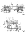
FIG. 1 is a general cross section showing a rotary connector device according to an embodiment in the present invention; -
FIG. 2 is an enlarged cross section of A portion inFIG. 1 ; -
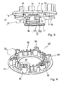
FIG. 3 is an exploded perspective view showing a rotor in the embodiment; -
FIG. 4 is a perspective view showing a spacer in the embodiment; -
FIG. 5A and FIG. 5B are views each showing a rotor cover portion in the embodiment; -
FIG. 6 is an enlarged cross section showing a section different from that inFIG. 2 ; -
FIG. 7 is a perspective view showing a cord housing in the embodiment; and -
FIG. 8 is an enlarged cross section showing the cord housing in the embodiment. - Hereinafter, an embodiment in the present invention will be explained with reference to the accompanying drawings.
As shown inFIG. 1 , a rotary connector device 1 is configured to include arotor 5 connected to a rotating steering shaft, a stator 30 connected to a fixed side of a vehicular body, and aspacer 50 and aflat cable 3 arranged in an annular space S between therotor 5 and the stator 30. Therotor 5 and the stator 30 are provided to be rotatable relative to each other as similar to the steering shaft and the vehicular body. - The
rotor 5 comprises a rotormain body 6, arotor cover portion 15 overlapping the rotormain body 6, and arotor attachment 23. The rotormain body 6 is made of a resin material capable of ensuring strength thereof, for example, a PBT (polybutylene terephthalate) resin, and is configured to have a predetermined strength with a toughening agent or the like. The rotormain body 6 includes a disc-shaped disc portion 7, and acylindrical portion 8 axially extending from the center of thedisc portion 7. Thecylindrical portion 8 is provided with athrough hole 9 therein. Agroove 11 is formed in a ring shape on the lower surface of thedisc portion 7 at an inner diameter side just proximal to an outer peripheral potion thereof. A diameter enlargedportion 10 is formed from a lower end portion of thecylindrical portion 8 to a predetermined position. - The
rotor cover portion 15 is made of, for example, a high lubricating resin of a polyacetal group or the like, and comprises adisc portion 16 covering an inner diameter side of thedisc portion 7 than thegroove 11 of thedisc portion 7, and acylindrical portion 17 covering an outer peripheral surface of thecylindrical portion 8. Thedisc portion 16 has a lower surface defining an upper end of the annular space S and thecylindrical portion 17 has an outer peripheral surface defining an inner periphery of the annular space S. Therotor cover portion 15 is fixed to the rotormain body 6 by hook clicks 18 and hookclicks 56. Thehook clicks 18 are provided at several locations in thedisc portion 16 immediately inside of an outer peripheral edge thereof, and are engaged inengagement portions 13 ofengagement holes 12 provided in thedisc portion 7 near the outer periphery thereof. In addition, thehook clicks 56 are, as shown inFIG. 5A , provided in a lower end portion of thecylindrical portion 17 at the inner edge. The hook click 56, as shown inFIG. 5B , comprises aflange portion 56a extending toward an inner diameter side, and anengagement portion 56b extending upwards from a tip end of theflange portion 56a, and theengagement portion 56b enters into a side of thethrough hole 9 of thecylindrical portion 8 for thecylindrical portion 17 to be engaged to thecylindrical portion 8. In addition, as shown inFIG. 2 , a lower end portion of thecylindrical portion 17 is provided with a diameter reducedportion 19 at the outer peripheral side and a diameter enlargedportion 20 at the inner peripheral side. - The
rotor attachment 23 is formed in a short, cylindrical shape, and has afitting portion 24 to be fitted in the diameter enlargedportion 10 of thecylindrical portion 8 in the rotormain body 6. As thefitting portion 24 is fitted in the diameter enlargedportion 10, an inner peripheral surface of therotor attachment 23 is flush with an upper inner peripheral surface of the throughhole 9 in thecylindrical portion 8. Further, thefitting portion 24 is provided with aflange portion 25 on the downward outer periphery. Theflange portion 25 supports, as described later, abottom cover 40 of the stator 30 from downward. - The stator 30, as shown in
FIG. 1 , comprises acylindrical case 31 an inner periphery of which defines an outer periphery of the annular space S, and the disc-shaped bottom cover 40 an upper surface of which defines a lower end of the annular space S. Thecase 31 is made of, for example, a high lubricating resin of a polyacetal group or the like, and is provided with a cylindricalinner wall 32 axially in parallel as a main part. Aflange portion 34 is provided across an entire circumference in an upper end portion of theinner wall 32 at an outer diameter side thereof. Anouter wall 33 rises in a ring shape across an entire circumference in an outer peripheral edge portion of theflange portion 34 to extend axially upwards. Theouter wall 33 extends inside thegroove 11 of thedisc portion 7 in the rotormain body 6 in such a manner as not to make contact with thedisc portion 7, and does not slide on thedisc portion 7. - A retaining
flange portion 35 extends in an inner diameter direction from an upper end of theinner wall 32 by a predetermined amount across an entire circumference. An upper surface of the retainingflange portion 35 is flush with an upper surface of theflange portion 34. This retainingflange portion 35 serves to prevent theflat cable 3 from pulling out from a constant position where theflat cable 3 is wound inside the annular space S. Further, as shown inFIG. 2 , a diameter enlargedportion 36 is formed on an inner surface of theinner wall 32 at the lower end portion thereof across the entire periphery. Theouter wall 33 extends further downwards from theflange portion 34 at several locations in the outer diameter side of theinner wall 32 to form outer walls 32a. A groove is formed at the inner peripheral side of theouter wall 33a between theouter wall 33a and theinner wall 32. - The
bottom cover 40 mainly comprises adisc portion 41, and afitting wall 42 rising to an axial predetermined position in an outer peripheral edge of thedisc portion 41. A tip end of thefitting wall 42 is fitted in the groove formed between theinner wall 32 and theouter wall 33a in thecase 31, and thebottom cover 40 is integral with thecase 31. On the other hand, a projectingportion 59 projecting across an entire circumference on an inner peripheral edge of thedisc portion 41 is fitted into the diameter enlargedportion 20 at the lower end of thecylindrical portion 17 in therotor cover portion 15. Thedisc portion 41 is relatively rotatably sandwiched between thecylindrical portion 17 and theflange portion 25 of therotor attachment 23. - The
spacer 50 is made of a resin having high lubricating properties such as, for example, a polyacetal group, and, as shown inFIG. 4 , supports aroller 45 on anannular plate portion 51, as well as is provided withguide portions 55 and guideportions 60 having a plurality of different configurations from each other. Theannular plate portion 51 is, as shown inFIG. 1 , positioned in a vertical direction by sandwiching the inner peripheral edge between thecylindrical portion 17 and thedisc portion 41 of thebottom cover 40 in the diameter reducedportion 19 of thecylindrical portion 17 in therotor cover portion 15, and by sandwiching the outer peripheral edge between theinner wall 32 and thedisc portion 41 of thebottom cover 40 in the diameter enlargedportion 36 of theinner wall 32 in thecase 31, and at the same time, is arranged to be rotatable relatively to therotor 5 and the stator 30. - The
flat cable 3 is arranged between thecylindrical portion 17 of therotor cover portion 15 and theguide portion 55 of thespacer 50 in the annular space S, and is reversed by aroller 45 and is arranged between theinner wall 32 of thecase 31 and theguide portion 55 of thespacer 50 to be in a winding state. In this arrangement, one end of theflat cable 3 in the winding state is pulled out outside of the annular space S from a side of therotor 5, and the other end is pulled out outside of the annular space S from a side of the stator 30. - In the present embodiment, the
flat cable 3 is pulled out from the side of therotor 5 to the annular space, but theflat cable 3 is accommodated in the side of therotor 5. For this reason, aflat cable groove 8a is formed across a circumferential predetermined range in a wall of thecylindrical portion 8 in the rotormain body 6. Theflat cable groove 8a has a deeper section than a width of theflat cable 3 and is opened axially downwards, and both ends thereof in the circumferential direction have pulling-out openings of theflat cable 3 to an outer peripheral side. The unillustrated pulling-out opening of one end is a pulling-out opening to a side of the rotormain body 6 and the other end is a cable pulling-outopening 8b to a side of the annular space S shown inFIG. 3 . Thecable pulling opening 8b is opened to be inclined from a radial direction to a circumferential direction in a direction in which theflat cable 3 is pulled out into the annular space S to be wound. - The
flat cable 3 is inserted from the downward side of theflat cable groove 8a, that is, from the open side to be retained therein. One end of theflat cable 3 in the side of therotor 5 is pulled out from the pulling-out opening of theflat cable groove 8a at the side of the rotormain body 6 to be bent, and extends to a radial predetermined position along the lower surface of thedisc portion 7. In addition, as shown inFIG. 3 , for pulling out theflat cable 3 to the side of the annular space S from theflat cable groove 8a, an openingportion 72 is formed in therotor cover portion 15. - The opening
portion 72 is, as shown inFIG. 6 , connected to anopening portion 72a of thecylindrical portion 17 and anopening portion 72b of thedisc portion 16. Theopening portion 72a is configured by cutting off thecylindrical portion 17 from a position immediately above the diameter reducedportion 19 to the upper end of thecylindrical portion 17 by a circumferential opening angle of approximately 90 degrees connecting to the circumferential end portion of theopening portion 72b. Theopening portion 72b is, as shown inFIG. 5A , configured by cutting off thedisc portion 16 in an arc shape along an inner peripheral side of the disc plane. A radial direction of theopening portion 72b has a width of the order of one-half of thedisc portion 16 in the inner side. Each ofcorner portions 73 at both ends of theopening portion 72b in the circumferential direction has a circular shape, which prevents theflat cable 3 from hooking into theopening portion 72b at assembling the rotormain body 6 and therotor cover portion 15. - In the present embodiment, as shown in
FIG. 3 , at the time of assembling the rotormain body 6 and therotor cover portion 15, it is required to pull theflat cable 3 out of the cable pulling-outopening 8b and to pass it through the openingportion 72 for leading it to the side of the annular space S in a state where the rotormain body 6 is axially separated from therotor cover portion 15. Here, when the rotormain body 6 is axially separated from therotor cover portion 15, a positional relation between the openingportion 72 and the cable pulling-outopening 8b is also axially shifted. At this time, in a case of passing theflat cable 3 through the openingportion 72, theflat cable 3 is axially pulled from the cable pulling-outopening 8b by thedisc portion 16, so that theflat cable 3 tends to be shifted out of theflat cable groove 8a. In addition, as theflat cable 3 is largely shifted in the axial direction, theflat cable 3 is shifted out of theflat cable groove 8a in which it is accommodated, to drop from the rotormain body 6. For prevention of the dropping, aconcave portion 70 is, as shown inFIG. 5A , provided in thedisc portion 16 of therotor cover portion 15. - The
concave portion 70 is, as shown inFIG. 3 , recessed from a side of the annular space S to a side of thedisc portion 7. Theconcave portion 70 is, as shown inFIG. 5A , formed from a hole edge to an outer peripheral edge of theopening portion 72b in thedisc portion 16, and across an angle of the order of 30 degrees as viewed from the center axis. In addition, theconcave portion 70 is provided in a position shifted from the center of the arc of theopening portion 72b in a direction in which theflat cable 3 is pulled out in the annular space S. Further, a bottom surface of theconcave portion 70 in a side of the annular space S forms, as shown inFIG. 3 , a plane in parallel to thedisc portion 16, and both side walls of the bottom surface form inclined surfaces opened toward the annular space S. - In addition, the assembling of the rotor
main body 6 and therotor cover portion 15 is performed with theflat cable 3 being placed on the bottom surface of theconcave portion 70 in the side of the annular space S, which prevents theflat cable 3 from dropping from the rotormain body 6. That is, theconcave portion 70 is recessed in an axial direction of thedisc portion 7 and a position where theflat cable 3 makes contact with therotor cover portion 15 is made closer to thedisc portion 7 by the recessed amount at the time of assembling the rotormain body 6 and therotor cover portion 15. Thereby an axial shift of theflat cable 3 is made small. In addition, as the axial shift of theflat cable 3 is made small at the assembling, the phenomenon that theflat cable 3 is out of theflat cable groove 8a and drops from the rotormain body 6 is prevented. Further, since theconcave portion 70 is shifted in position in a direction where theflat cable 3 is pulled out of the center of the arc of theopening portion 72b, theflat cable 3 tends to be easily positioned on the bottom surface of theconcave portion 70 at the assembling, thus easily bringing out the effect of the shift prevention by theconcave portion 70. Further, since both the side walls of theconcave portion 70 form the inclined surfaces, theflat cable 3 is easily led to the bottom surface of theconcave portion 70 at the time of passing theflat cable 3 through the openingportion 72 for assembly. - A diameter enlarged
portion 75 is provided in an outer peripheral portion of thecylindrical portion 8 corresponding to a position and a size of theopening portion 72a (refer toFIG. 6 ). The diameter enlargedportion 75 has an outer diameter larger by a thickness of thecylindrical portion 17 than thecylindrical portion 8, and is fitted in a portion formed by cutting off thecylindrical portion 17 by theopening portion 72a. As the diameter enlargedportion 75 is fitted therein, the diameter enlargedportion 75 is flush with an outer periphery of thecylindrical portion 17 to be integral therewith. In addition, the cable pulling-outopening 8b is formed on the diameter enlargedportion 75. In theopening portion 72b, a thickeningportion 74 is provided in thedisc portion 7. The thickeningportion 74 is formed in an arc shape positioned and sized to correspond to theopening portion 72b, and is fitted in theopening portion 72b to be flush with thedisc portion 16. Here, in the openingportion 72 in which the diameter enlargedportion 75 is fitted, theflat cable 3 makes direct contact with the rotormain body 6 not made of a high lubricating resin, but since the contact portion is near a position where theflat cable 3 is pulled out in the annular space S, a contact length between theflat cable 3 and the rotormain body 6 is small. Therefore there is no problem with generation of sliding noises. - In addition, in the present embodiment, the
disc portion 7 of the rotormain body 6 is adapted to be capable of taking out the wiring from a predetermined position on the upper surface. In addition, as shown inFIG. 7 , acord housing 62 is provided as one of the taking-out openings. Thecord housing 62 is provided to be swollen toward the upper side on the upper surface of thedisc portion 7 in a position corresponding to a terminal of theflat cable 3 as shown inFIG. 7 . In addition, thecord housing 62 is configured such that anopening portion 62c opened toward the outer periphery of the rotormain body 6 is surrounded by bothside surfaces 62e rising axially at a right angle from the upper surface of thedisc portion 7 and aceiling surface 62g. As shown inFIG. 8 , the backside of thecord housing 62 is opened, and forms a space for connecting theflat cable 3 and thecord 4. Afastening stopper 62a extends downwards from theceiling surface 62g in theopening portion 62c of thecord housing 62. Thefastening stopper 62a has a lower surface which is in parallel to thedisc portion 16 and is provided with a sliding stop formed of fine, grooved, concave and convex portions cut at a right angle in a radial direction. In addition, thedisc portion 7 has an outer peripheral portion including thegroove 11, which is cut off by a constant width radially outwards from a position opposing thefastening stopper 62a. - The
rotor cover portion 15 is, as shown inFIG. 8 , provided with afastening stopper 58a opposing thefastening portion 62a for retaining thecord 4, and an outerperipheral portion 58 corresponding to the cut-off portion of thedisc portion 7 in the rotormain body 6. The outerperipheral portion 58 has the same configuration as the outer peripheral edge of thecorresponding disc portion 7, and is provided with agroove 58b corresponding to thegroove 11 of the rotormain body 6. When therotor cover portion 15 is engaged to the rotormain body 6 for connection, as shown inFIG. 7 the outerperipheral portion 58 is fitted into the cut-off portion of thecord housing 62 in an outer peripheral lower part thereof without a gap to be integral therewith, thus forming a smooth outer periphery of therotor 5. Thegroove 58b in the inner diameter side of the outer periphery also becomes flush with thegroove 11 to form an integrated groove in a smooth ring shape. - The
fastening stopper 58a rises up at a right angle from an outer peripheral edge of therotor cover portion 15 toward thecord housing 62. An upper surface of thefastening stopper 58a is provided with a surface which is in parallel to thedisc portion 16 and opposes a surface of a tip end portion of thefastening stopper 62a. A tip end portion of thefastening stopper 58a and the tip end portion of thefastening stopper 62a respectively have the same width in a radial direction. Thecord 4 is, as shown inFIG. 8 , configured to be provided withcord core wires 4a inside and acord covering portion 4b for covering the surrounding area of thecord core wires 4a. The severalcord core wires 4a inside thecord covering portion 4b are appropriately put together so as to form a single wire, which is covered with thecord covering portion 4b. Thecord covering portion 4b is made of a flexible material, for example, polyethylene. - The
cord 4 is sandwiched between thefastening stopper 58a and thefastening stopper 62a for the retaining by squeezing thecord covering portion 4b of thecord 4 therewith, and thecord 4 can be taken out of the rotormain body 6. For thus sandwiching thecord 4 between thefastening stopper 58a and thefastening stopper 62a to be retained therebetween, a distance between the opposingfastening stopper 58a andfastening stopper 62a is made smaller than a diameter of thecord 4, and longer than a diameter of thecord core wire 4a. The retaining of thecord 4 by thefastening stopper 58a and thefastening stopper 62a prevents thecord 4 from being pulled out of therotor 5 or shifted therefrom. In addition, the sliding stop formed of the grooved concave and convex portions provided on the lower surface of thefastening stopper 62a enhances this effect. Further, the openingportion 62c is appropriately sectioned in the circumferential direction by providing projections in a circumferential direction of thecord 4, and configurations sectioned to correspond to the projections are provided also in the outerperipheral portion 58, thus making it possible to retain different kinds ofcords 4 in a line at the same time. - The present embodiment is configured as described above. That is, the present embodiment is provided with the rotary connector device 1 in which the annular space S is formed between the
rotor 5 and the stator 30, and theflat cable 3, both ends of which are pulled out through therotor 5 and the stator 30 outside of the annular space S, is accommodated in the annular space S in a state where the winding direction thereof is reversed in the halfway. In the rotary connector device 1, therotor 5 includes the rotormain body 6 made of PBT, and therotor cover portion 15 made of a polyacetal resin, wherein the rotormain body 6 includes thedisc portion 7 and thecylindrical portion 8 axially extending from the center of thedisc portion 7, and therotor cover portion 15 includes thedisc portion 16 overlapping thedisc portion 7 of the rotormain portion 6, and thecylindrical portion 17 overlapping thecylindrical portion 8 of the rotormain body 6, each facing the annular space S. Therefore the rotormain body 6 is made of the PBT resin, and the strength of the rotary connector device 1 can be ensured. In addition, since therotor cover portion 15 is made of the polyacetal resin, the sliding properties of the contact surface between therotor 5 and theflat cable 3 can be enhanced to reduce generation of the sliding noises between therotor 5 and theflat cable 3. By thus forming the rotormain body 6 and therotor cover portion 15 with the different materials, the strength of the rotary connector device 1 can be ensured and at the same time, the generation of the sliding noises thereof can be reduced. Further, since the rotormain body 6 is made of the PBT resin, heat resistance properties and weather resistance properties of the rotary connector device 1 can be ensured. - In addition to the above, in the present embodiment, the
case 31 and thespacer 50 each are made of the polyacetal resin. Therefore the sliding resistance between thecase 31 and theflat cable 3 in the annular space S can be reduced to reduce the generation of the sliding noises, and similarly by reducing the sliding resistance between thespacer 50 and theflat cable 3, the generation of the sliding noises therebeween can be reduced. In addition, not only the sliding resistance to theflat cable 3 but also the direct sliding resistance between thebottom cover 40 and therotor 5 can be reduced to reduce the generation of the sliding noises therebeween. - In the present embodiment, the
flat cable 3 is retained by the rotormain body 6 made of the PBT resin, and is pulled out into the annular space S from the openingportion 72 provided in therotor cover portion 15. Therefore the terminal of theflat cable 3 can be stably retained by the material having the strength. - Further, in the present embodiment, the
disc portion 16 of therotor cover portion 15 is provided with theconcave portion 70 recessed to a side of thedisc portion 7 of the rotormain body 6 in a section of thedisc portion 16 corresponding to the openingportion 72. according to this structure, when the assembling between the rotormain body 6 and therotor cover portion 15 is performed with theflat cable 3 being placed on the bottom surface of theconcave portion 70 in a side of the annular space S, the phenomenon that theflat cable 3 is out of theflat cable groove 8a to drop from the rotormain body 6 is prevented. - In addition, the
concave portion 70 is provided to be shifted in position from the center of the arc of theopening portion 72b in a direction where theflat cable 3 is pulled out. Therefore theflat cable 3 tends to be easily positioned on the bottom surface of theconcave portion 70 at the time of assembling to enhance the effect of the shift prevention by theconcave portion 70. Further, theconcave portion 70 is configured such that each of both side walls of the bottom surface is formed as an inclined surface opened toward the annular space S. Therefore at the time of passing theflat cable 3 through the openingportion 72 for assembly, theflat cable 3 tends to be easily led to the bottom surface in the side of theconcave portion 70. As described above, theconcave portion 70 can prevent theflat cable 3 from dropping from the rotormain body 6 at the time of assembling the rotormain body 6 and therotor cover portion 15. As a result, work efficiency of an assembling work of the rotormain body 6 and therotor cover portion 15 can be improved to reduce the manufacturing costs. - Further, in the present embodiment, the
cord 4, which is connected to theflat cable 3 and is pulled out of the outer peripheral portion of therotor 5, is sandwiched between thedisc portion 16 of therotor cover portion 15 and thedisc portion 7 of the rotormain body 6 to be retained therebetween. Therefore thecord 4 can be sandwiched between the rotormain body 6 and therotor cover portion 15 to be retained without using other new retaining members other than the rotormain body 6 and therotor cover portion 15. Accordingly, thecord 4 can be pulled out of therotor 5 without increasing the numbers of components in use to reduce costs and the assembling man-hours. - In the present embodiment, the polyacetal resin is shown as an example of the high lubricating resin material used in the
rotor cover portion 15, thecase 31, and thespacer 50, but the other material having the similar properties may be used as needed as an alternative for it. For example, a PTFE material may be used as the high lubricating resin material or a resin material appropriately containing a lubricating agent may be used. These alternatives may be used likewise instead of the PBT resin used in the rotormain body 6, and the other material having the appropriate strength, for example, a PEN resin may be used as an alternative. - Further, the present embodiment adopts the rotary connector device of reversing the winding direction of the
flat cable 3 in the halfway, but the present invention may be applied to a rotary connector device of not reversing the winding direction of theflat cable 3 in the halfway, for example, of a spiral type. - In addition, the configuration, the position, and the area of the opening
portion 72 are not limited to those in the present embodiment, and may differ as needed. For example, in the present embodiment, the angle of openingportion 72 is set to approximately 90 degrees, but may be 120 degrees or 60 degrees. Also in regard to the position of the openingportion 72, theopening portion 72a is formed from a position immediately above the diameter reducedportion 19, but as long as theflat cable 3 can pass through the openingportion 72, a position thereof may be not formed immediately above it. Further, in the present embodiment, the width of theopening portion 72b is set to the degree of one-half of thedisc portion 16 at the inside, but is not limited thereto. Further, the configuration, the position, the area, and the axial depth of theconcave portion 70 are not limited to those of the present embodiment, and as long as theconcave portion 70 can have an axial allowance for placing theflat cable 3 on the bottom surface at the time of assembling, theconcave portion 70 may be changed as needed to a size and a position required at the time of assembling.
While only the selected embodiment has been chosen to illustrate the present invention, it will be apparent to those skilled in the art from this disclosure that various changes and modifications can be made therein without departing from the scope of the invention as defined in the appended claims. Furthermore, the foregoing description of the embodiment according to the present invention is provided for illustration only, and not for the purpose of limiting the invention as defined by the appended claims and their equivalents. -
- 1
- Rotary connector device
- 3
- Flat cable
- 4
- Cord
- 4a
- Cord core wire
- 4b
- Cord covering portion
- 5
- Rotor
- 6
- Rotor main body
- 7
- Disc portion
- 8
- Cylindrical portion
- 8a
- Flat cable groove
- 8b
- Cable pulling-out opening
- 9
- Through hole
- 10
- Diameter enlarged portion
- 11
- Groove
- 12
- Engagement hole
- 13
- Engagement portion
- 15
- Rotor cover portion
- 16
- Disc portion
- 17
- Cylindrical portion
- 18
- Hook click
- 19
- Diameter reduced portion
- 20
- Diameter enlarged portion
- 23
- Rotor attachment
- 24
- Fitting portion
- 25
- Flange portion
- 30
- Stator
- 31
- Case
- 32
- Inner wall
- 33
- Outer wall
- 33a
- Outer wall
- 34
- Flange portion
- 35
- Retaining flange portion
- 36
- Diameter enlarged portion
- 40
- Bottom cover
- 41
- Disc portion
- 42
- Fitting wall
- 45
- Roller
- 50
- Spacer
- 51
- Annular plate portion
- 55
- Guide portion
- 56
- Hook portion
- 56a
- Flange portion
- 56b
- Engagement portion
- 58
- Outer peripheral portion
- 58a
- Fastening stopper
- 58b
- Groove
- 59
- Projecting portion
- 60
- Guide portion
- 62
- Cord housing
- 62a
- Fastening stopper
- 62c
- Opening portion
- 62e
- Side surface
- 62g
- Ceiling surface
- 70
- Concave portion
- 72
- Opening portion
- 72a
- Opening portion
- 72b
- Opening portion
- 73
- Corner portion
- 74
- Thickening portion
- 75
- Diameter enlarged portion
- S
- Annular space
the rotor main body comprises:
Claims (6)
- A rotary connector device comprising:a rotor (5);a stator (30) forming an annular space (S) with the rotor (5) between the rotor and the stator; anda flat cable (3) accommodated in the annular space (S), of which both sides are pulled out outside of the annular space (S) via the rotor (5) and the stator (30),wherein
the rotor (5) comprises:a rotor main body (6) made of a resin with high strength; anda rotor cover portion (15) made of a resin with high lubricating properties,wherein
the rotor main body (6) comprises:a disc portion (7); anda cylindrical portion (8) axially extending from the center of the disc portion (7), andthe rotor cover portion (15) comprises:a disc portion (16) overlapping the disc portion (7) of the rotor main body (6); anda cylindrical portion (17) overlapping the cylindrical portion (8) of the rotor main body (6), the disc portion (16) and the cylindrical portion (17) respectively facing the annular space (S). - A rotary connector device according to claim 1, wherein
the flat cable (3) is retained in the rotor main body (6), and is pulled out in the annular space (S) from an opening portion (72b) formed in the rotor cover portion (15). - A rotary connector device according to claim 2, wherein
a section of the disc portion (7) in the rotor cover portion (15) corresponding to the opening portion (72b) is provided with a concave portion (70) recessed in a disc portion side of the rotor main body (6). - A rotary connector device according to claim 3, wherein
the concave portion (70) is provided to be shifted in position in a direction where the flat cable (3) is pulled out from the center of the arc of the opening portion (72b). - A rotary connector device according to claim 3 or 4, wherein
the concave portion (70) is configured to form both side walls of the bottom as inclined surfaces opened toward the annular space (S). - A rotary connector device according to any of claims 1 to 5, further comprising:a cord (4) which is connected to the flat cable (3) and is pulled out of an outer peripheral portion (58) of the rotor (5), whereinthe cord (4) is sandwiched between the disc portion (16) of the rotor cover portion (15) and the disc portion (7) of the rotor main body (6) to be retained therebetween.
Applications Claiming Priority (1)
| Application Number | Priority Date | Filing Date | Title |
|---|---|---|---|
| JP2012017233A JP2013157209A (en) | 2012-01-30 | 2012-01-30 | Rotary connector device |
Publications (2)
| Publication Number | Publication Date |
|---|---|
| EP2621030A1 true EP2621030A1 (en) | 2013-07-31 |
| EP2621030B1 EP2621030B1 (en) | 2015-04-15 |
Family
ID=47709794
Family Applications (1)
| Application Number | Title | Priority Date | Filing Date |
|---|---|---|---|
| EP13000262.9A Not-in-force EP2621030B1 (en) | 2012-01-30 | 2013-01-18 | Rotary connector device |
Country Status (5)
| Country | Link |
|---|---|
| US (1) | US8986018B2 (en) |
| EP (1) | EP2621030B1 (en) |
| JP (1) | JP2013157209A (en) |
| KR (1) | KR101738185B1 (en) |
| CN (1) | CN103223916B (en) |
Families Citing this family (8)
| Publication number | Priority date | Publication date | Assignee | Title |
|---|---|---|---|---|
| CN104682326A (en) * | 2013-12-03 | 2015-06-03 | 国家电网公司 | Small-diameter bending spherical adjusting device for armored cable based on double convex rings |
| CN104319572B (en) * | 2014-10-16 | 2016-08-24 | 宁波帝杨电子科技有限公司 | Trailer electrical cnnector |
| CN104319573B (en) * | 2014-10-16 | 2017-02-15 | 宁波帝杨电子科技有限公司 | Trailer electric connector with switchable exposed interfaces |
| US10614328B2 (en) * | 2014-12-30 | 2020-04-07 | Joyson Safety Acquisition LLC | Occupant monitoring systems and methods |
| CN105416218B (en) * | 2015-12-11 | 2018-03-13 | 山西中航锦恒科技有限公司 | A kind of floated clock spring and its adjustment method |
| CN106655597B (en) * | 2016-11-22 | 2018-02-09 | 大工科技(上海)有限公司 | A kind of motor apparatus with rotation termination |
| WO2020121741A1 (en) * | 2018-12-13 | 2020-06-18 | 古河電気工業株式会社 | Rotary connector device |
| CN112928648B (en) * | 2021-03-29 | 2022-09-27 | 正耐电气股份有限公司 | High-voltage alternating-current metal closed ring network switch equipment |
Citations (2)
| Publication number | Priority date | Publication date | Assignee | Title |
|---|---|---|---|---|
| US20090317984A1 (en) * | 2008-06-19 | 2009-12-24 | Niles Co., Ltd. | Rotary Connector Device |
| EP2546937A1 (en) * | 2011-07-12 | 2013-01-16 | Niles Co., Ltd. | Rotational connector device |
Family Cites Families (8)
| Publication number | Priority date | Publication date | Assignee | Title |
|---|---|---|---|---|
| EP0659614B1 (en) * | 1993-12-22 | 1998-08-19 | Nihon Plast Co., Ltd. | Reel device for cable |
| US5593310A (en) * | 1993-12-27 | 1997-01-14 | Nihon Plast Co., Ltd. | Cable type electric connector |
| KR100295231B1 (en) * | 1996-06-28 | 2001-09-17 | 스즈키 다케토시 | Rotary Connector Device |
| DE19926278C1 (en) * | 1999-06-09 | 2001-02-15 | Kostal Leopold Gmbh & Co Kg | Device for transmitting energy |
| JP3676146B2 (en) * | 1999-10-22 | 2005-07-27 | 古河電気工業株式会社 | Rotating connector |
| JP4355229B2 (en) * | 2004-02-12 | 2009-10-28 | アルプス電気株式会社 | Rotating connector |
| DE102005002676B3 (en) * | 2005-01-20 | 2006-06-14 | Tyco Electronics Amp Gmbh | Spring mounting for steering columns comprises outer ring fixed to vehicle bodywork and inner ring which can rotate, flexible roller being mounted between rings and flat cable fitted into groove inside outer ring passing around it |
| JP4491013B2 (en) * | 2007-12-17 | 2010-06-30 | アルプス電気株式会社 | Rotating connector |
-
2012
- 2012-01-30 JP JP2012017233A patent/JP2013157209A/en active Pending
- 2012-12-21 CN CN201210562525.5A patent/CN103223916B/en not_active Expired - Fee Related
- 2012-12-26 KR KR1020120152891A patent/KR101738185B1/en active IP Right Grant
-
2013
- 2013-01-18 EP EP13000262.9A patent/EP2621030B1/en not_active Not-in-force
- 2013-01-29 US US13/752,676 patent/US8986018B2/en not_active Expired - Fee Related
Patent Citations (3)
| Publication number | Priority date | Publication date | Assignee | Title |
|---|---|---|---|---|
| US20090317984A1 (en) * | 2008-06-19 | 2009-12-24 | Niles Co., Ltd. | Rotary Connector Device |
| JP2010003514A (en) | 2008-06-19 | 2010-01-07 | Niles Co Ltd | Rotary connector device |
| EP2546937A1 (en) * | 2011-07-12 | 2013-01-16 | Niles Co., Ltd. | Rotational connector device |
Also Published As
| Publication number | Publication date |
|---|---|
| US8986018B2 (en) | 2015-03-24 |
| CN103223916A (en) | 2013-07-31 |
| CN103223916B (en) | 2015-11-18 |
| KR20130087998A (en) | 2013-08-07 |
| US20130196518A1 (en) | 2013-08-01 |
| EP2621030B1 (en) | 2015-04-15 |
| JP2013157209A (en) | 2013-08-15 |
| KR101738185B1 (en) | 2017-05-19 |
Similar Documents
| Publication | Publication Date | Title |
|---|---|---|
| EP2621030B1 (en) | Rotary connector device | |
| EP2612398B1 (en) | Shield connector | |
| EP1650838B1 (en) | Rotary connector | |
| EP2555345B1 (en) | Rotary connector device | |
| US7594819B2 (en) | Rotary connector | |
| JP5886148B2 (en) | Rotating connector device | |
| JP5568126B2 (en) | Worm wheel, reducer and motor with reducer | |
| US8727936B2 (en) | Rotary connector | |
| CN107492961B (en) | Rotor and motor having the same | |
| EP2860857A2 (en) | Outer-rotor motor | |
| US8851901B2 (en) | Rotary connector device | |
| US5952908A (en) | Coil bobbin and an exciting coil assembly | |
| US8740626B2 (en) | Rotational connector device including a spacer disposed in an annular space formed between a rotor and a stator | |
| CN209526599U (en) | Motor | |
| EP2848813A1 (en) | Electric pump apparatus | |
| EP3376645A1 (en) | Geared motor and method for producing geared motor | |
| US20200161925A1 (en) | Electric motor | |
| JP2023047076A (en) | wire harness | |
| KR102517687B1 (en) | Motor and method for manufacturing of the same | |
| CN205956187U (en) | Low noise automobile dragging line sleeve pipe | |
| WO2023234006A1 (en) | Wire harness | |
| US11843210B2 (en) | Rotary connector device | |
| CN113226892B (en) | Sensing apparatus | |
| WO2022059358A1 (en) | Wire harness | |
| JP2022057508A (en) | motor |
Legal Events
| Date | Code | Title | Description |
|---|---|---|---|
| PUAI | Public reference made under article 153(3) epc to a published international application that has entered the european phase |
Free format text: ORIGINAL CODE: 0009012 |
|
| AK | Designated contracting states |
Kind code of ref document: A1 Designated state(s): AL AT BE BG CH CY CZ DE DK EE ES FI FR GB GR HR HU IE IS IT LI LT LU LV MC MK MT NL NO PL PT RO RS SE SI SK SM TR |
|
| AX | Request for extension of the european patent |
Extension state: BA ME |
|
| 17P | Request for examination filed |
Effective date: 20131114 |
|
| RBV | Designated contracting states (corrected) |
Designated state(s): AL AT BE BG CH CY CZ DE DK EE ES FI FR GB GR HR HU IE IS IT LI LT LU LV MC MK MT NL NO PL PT RO RS SE SI SK SM TR |
|
| RAP1 | Party data changed (applicant data changed or rights of an application transferred) |
Owner name: VALEO JAPAN CO., LTD. |
|
| GRAP | Despatch of communication of intention to grant a patent |
Free format text: ORIGINAL CODE: EPIDOSNIGR1 |
|
| INTG | Intention to grant announced |
Effective date: 20141113 |
|
| GRAS | Grant fee paid |
Free format text: ORIGINAL CODE: EPIDOSNIGR3 |
|
| GRAA | (expected) grant |
Free format text: ORIGINAL CODE: 0009210 |
|
| AK | Designated contracting states |
Kind code of ref document: B1 Designated state(s): AL AT BE BG CH CY CZ DE DK EE ES FI FR GB GR HR HU IE IS IT LI LT LU LV MC MK MT NL NO PL PT RO RS SE SI SK SM TR |
|
| REG | Reference to a national code |
Ref country code: GB Ref legal event code: FG4D Ref country code: CH Ref legal event code: EP |
|
| REG | Reference to a national code |
Ref country code: IE Ref legal event code: FG4D |
|
| REG | Reference to a national code |
Ref country code: AT Ref legal event code: REF Ref document number: 722429 Country of ref document: AT Kind code of ref document: T Effective date: 20150515 |
|
| REG | Reference to a national code |
Ref country code: DE Ref legal event code: R096 Ref document number: 602013001482 Country of ref document: DE Effective date: 20150528 |
|
| REG | Reference to a national code |
Ref country code: NL Ref legal event code: VDEP Effective date: 20150415 |
|
| REG | Reference to a national code |
Ref country code: AT Ref legal event code: MK05 Ref document number: 722429 Country of ref document: AT Kind code of ref document: T Effective date: 20150415 |
|
| REG | Reference to a national code |
Ref country code: LT Ref legal event code: MG4D |
|
| PG25 | Lapsed in a contracting state [announced via postgrant information from national office to epo] |
Ref country code: NL Free format text: LAPSE BECAUSE OF FAILURE TO SUBMIT A TRANSLATION OF THE DESCRIPTION OR TO PAY THE FEE WITHIN THE PRESCRIBED TIME-LIMIT Effective date: 20150415 |
|
| PG25 | Lapsed in a contracting state [announced via postgrant information from national office to epo] |
Ref country code: HR Free format text: LAPSE BECAUSE OF FAILURE TO SUBMIT A TRANSLATION OF THE DESCRIPTION OR TO PAY THE FEE WITHIN THE PRESCRIBED TIME-LIMIT Effective date: 20150415 Ref country code: ES Free format text: LAPSE BECAUSE OF FAILURE TO SUBMIT A TRANSLATION OF THE DESCRIPTION OR TO PAY THE FEE WITHIN THE PRESCRIBED TIME-LIMIT Effective date: 20150415 Ref country code: PT Free format text: LAPSE BECAUSE OF FAILURE TO SUBMIT A TRANSLATION OF THE DESCRIPTION OR TO PAY THE FEE WITHIN THE PRESCRIBED TIME-LIMIT Effective date: 20150817 Ref country code: FI Free format text: LAPSE BECAUSE OF FAILURE TO SUBMIT A TRANSLATION OF THE DESCRIPTION OR TO PAY THE FEE WITHIN THE PRESCRIBED TIME-LIMIT Effective date: 20150415 Ref country code: NO Free format text: LAPSE BECAUSE OF FAILURE TO SUBMIT A TRANSLATION OF THE DESCRIPTION OR TO PAY THE FEE WITHIN THE PRESCRIBED TIME-LIMIT Effective date: 20150715 Ref country code: LT Free format text: LAPSE BECAUSE OF FAILURE TO SUBMIT A TRANSLATION OF THE DESCRIPTION OR TO PAY THE FEE WITHIN THE PRESCRIBED TIME-LIMIT Effective date: 20150415 |
|
| PG25 | Lapsed in a contracting state [announced via postgrant information from national office to epo] |
Ref country code: LV Free format text: LAPSE BECAUSE OF FAILURE TO SUBMIT A TRANSLATION OF THE DESCRIPTION OR TO PAY THE FEE WITHIN THE PRESCRIBED TIME-LIMIT Effective date: 20150415 Ref country code: GR Free format text: LAPSE BECAUSE OF FAILURE TO SUBMIT A TRANSLATION OF THE DESCRIPTION OR TO PAY THE FEE WITHIN THE PRESCRIBED TIME-LIMIT Effective date: 20150716 Ref country code: AT Free format text: LAPSE BECAUSE OF FAILURE TO SUBMIT A TRANSLATION OF THE DESCRIPTION OR TO PAY THE FEE WITHIN THE PRESCRIBED TIME-LIMIT Effective date: 20150415 Ref country code: RS Free format text: LAPSE BECAUSE OF FAILURE TO SUBMIT A TRANSLATION OF THE DESCRIPTION OR TO PAY THE FEE WITHIN THE PRESCRIBED TIME-LIMIT Effective date: 20150415 Ref country code: IS Free format text: LAPSE BECAUSE OF FAILURE TO SUBMIT A TRANSLATION OF THE DESCRIPTION OR TO PAY THE FEE WITHIN THE PRESCRIBED TIME-LIMIT Effective date: 20150815 |
|
| REG | Reference to a national code |
Ref country code: DE Ref legal event code: R097 Ref document number: 602013001482 Country of ref document: DE |
|
| REG | Reference to a national code |
Ref country code: FR Ref legal event code: PLFP Year of fee payment: 4 |
|
| PG25 | Lapsed in a contracting state [announced via postgrant information from national office to epo] |
Ref country code: EE Free format text: LAPSE BECAUSE OF FAILURE TO SUBMIT A TRANSLATION OF THE DESCRIPTION OR TO PAY THE FEE WITHIN THE PRESCRIBED TIME-LIMIT Effective date: 20150415 Ref country code: DK Free format text: LAPSE BECAUSE OF FAILURE TO SUBMIT A TRANSLATION OF THE DESCRIPTION OR TO PAY THE FEE WITHIN THE PRESCRIBED TIME-LIMIT Effective date: 20150415 |
|
| PLBE | No opposition filed within time limit |
Free format text: ORIGINAL CODE: 0009261 |
|
| STAA | Information on the status of an ep patent application or granted ep patent |
Free format text: STATUS: NO OPPOSITION FILED WITHIN TIME LIMIT |
|
| PG25 | Lapsed in a contracting state [announced via postgrant information from national office to epo] |
Ref country code: PL Free format text: LAPSE BECAUSE OF FAILURE TO SUBMIT A TRANSLATION OF THE DESCRIPTION OR TO PAY THE FEE WITHIN THE PRESCRIBED TIME-LIMIT Effective date: 20150415 Ref country code: RO Free format text: LAPSE BECAUSE OF NON-PAYMENT OF DUE FEES Effective date: 20150415 Ref country code: CZ Free format text: LAPSE BECAUSE OF FAILURE TO SUBMIT A TRANSLATION OF THE DESCRIPTION OR TO PAY THE FEE WITHIN THE PRESCRIBED TIME-LIMIT Effective date: 20150415 Ref country code: SK Free format text: LAPSE BECAUSE OF FAILURE TO SUBMIT A TRANSLATION OF THE DESCRIPTION OR TO PAY THE FEE WITHIN THE PRESCRIBED TIME-LIMIT Effective date: 20150415 |
|
| 26N | No opposition filed |
Effective date: 20160118 |
|
| PG25 | Lapsed in a contracting state [announced via postgrant information from national office to epo] |
Ref country code: IT Free format text: LAPSE BECAUSE OF FAILURE TO SUBMIT A TRANSLATION OF THE DESCRIPTION OR TO PAY THE FEE WITHIN THE PRESCRIBED TIME-LIMIT Effective date: 20150415 |
|
| PG25 | Lapsed in a contracting state [announced via postgrant information from national office to epo] |
Ref country code: SI Free format text: LAPSE BECAUSE OF FAILURE TO SUBMIT A TRANSLATION OF THE DESCRIPTION OR TO PAY THE FEE WITHIN THE PRESCRIBED TIME-LIMIT Effective date: 20150415 Ref country code: BE Free format text: LAPSE BECAUSE OF NON-PAYMENT OF DUE FEES Effective date: 20160131 |
|
| PG25 | Lapsed in a contracting state [announced via postgrant information from national office to epo] |
Ref country code: BE Free format text: LAPSE BECAUSE OF FAILURE TO SUBMIT A TRANSLATION OF THE DESCRIPTION OR TO PAY THE FEE WITHIN THE PRESCRIBED TIME-LIMIT Effective date: 20150415 Ref country code: LU Free format text: LAPSE BECAUSE OF FAILURE TO SUBMIT A TRANSLATION OF THE DESCRIPTION OR TO PAY THE FEE WITHIN THE PRESCRIBED TIME-LIMIT Effective date: 20160118 |
|
| REG | Reference to a national code |
Ref country code: CH Ref legal event code: PL |
|
| PG25 | Lapsed in a contracting state [announced via postgrant information from national office to epo] |
Ref country code: MC Free format text: LAPSE BECAUSE OF FAILURE TO SUBMIT A TRANSLATION OF THE DESCRIPTION OR TO PAY THE FEE WITHIN THE PRESCRIBED TIME-LIMIT Effective date: 20150415 |
|
| PG25 | Lapsed in a contracting state [announced via postgrant information from national office to epo] |
Ref country code: LI Free format text: LAPSE BECAUSE OF NON-PAYMENT OF DUE FEES Effective date: 20160131 Ref country code: CH Free format text: LAPSE BECAUSE OF NON-PAYMENT OF DUE FEES Effective date: 20160131 |
|
| REG | Reference to a national code |
Ref country code: IE Ref legal event code: MM4A |
|
| PG25 | Lapsed in a contracting state [announced via postgrant information from national office to epo] |
Ref country code: IE Free format text: LAPSE BECAUSE OF NON-PAYMENT OF DUE FEES Effective date: 20160118 |
|
| PG25 | Lapsed in a contracting state [announced via postgrant information from national office to epo] |
Ref country code: SE Free format text: LAPSE BECAUSE OF FAILURE TO SUBMIT A TRANSLATION OF THE DESCRIPTION OR TO PAY THE FEE WITHIN THE PRESCRIBED TIME-LIMIT Effective date: 20150415 |
|
| REG | Reference to a national code |
Ref country code: FR Ref legal event code: PLFP Year of fee payment: 5 |
|
| PG25 | Lapsed in a contracting state [announced via postgrant information from national office to epo] |
Ref country code: MT Free format text: LAPSE BECAUSE OF FAILURE TO SUBMIT A TRANSLATION OF THE DESCRIPTION OR TO PAY THE FEE WITHIN THE PRESCRIBED TIME-LIMIT Effective date: 20150415 |
|
| REG | Reference to a national code |
Ref country code: FR Ref legal event code: PLFP Year of fee payment: 6 |
|
| PG25 | Lapsed in a contracting state [announced via postgrant information from national office to epo] |
Ref country code: SM Free format text: LAPSE BECAUSE OF FAILURE TO SUBMIT A TRANSLATION OF THE DESCRIPTION OR TO PAY THE FEE WITHIN THE PRESCRIBED TIME-LIMIT Effective date: 20150415 Ref country code: HU Free format text: LAPSE BECAUSE OF FAILURE TO SUBMIT A TRANSLATION OF THE DESCRIPTION OR TO PAY THE FEE WITHIN THE PRESCRIBED TIME-LIMIT; INVALID AB INITIO Effective date: 20130118 Ref country code: CY Free format text: LAPSE BECAUSE OF FAILURE TO SUBMIT A TRANSLATION OF THE DESCRIPTION OR TO PAY THE FEE WITHIN THE PRESCRIBED TIME-LIMIT Effective date: 20150415 |
|
| PG25 | Lapsed in a contracting state [announced via postgrant information from national office to epo] |
Ref country code: TR Free format text: LAPSE BECAUSE OF FAILURE TO SUBMIT A TRANSLATION OF THE DESCRIPTION OR TO PAY THE FEE WITHIN THE PRESCRIBED TIME-LIMIT Effective date: 20150415 Ref country code: MT Free format text: LAPSE BECAUSE OF FAILURE TO SUBMIT A TRANSLATION OF THE DESCRIPTION OR TO PAY THE FEE WITHIN THE PRESCRIBED TIME-LIMIT Effective date: 20160131 Ref country code: MK Free format text: LAPSE BECAUSE OF FAILURE TO SUBMIT A TRANSLATION OF THE DESCRIPTION OR TO PAY THE FEE WITHIN THE PRESCRIBED TIME-LIMIT Effective date: 20150415 |
|
| PG25 | Lapsed in a contracting state [announced via postgrant information from national office to epo] |
Ref country code: BG Free format text: LAPSE BECAUSE OF FAILURE TO SUBMIT A TRANSLATION OF THE DESCRIPTION OR TO PAY THE FEE WITHIN THE PRESCRIBED TIME-LIMIT Effective date: 20150415 |
|
| PG25 | Lapsed in a contracting state [announced via postgrant information from national office to epo] |
Ref country code: AL Free format text: LAPSE BECAUSE OF FAILURE TO SUBMIT A TRANSLATION OF THE DESCRIPTION OR TO PAY THE FEE WITHIN THE PRESCRIBED TIME-LIMIT Effective date: 20150415 |
|
| PGFP | Annual fee paid to national office [announced via postgrant information from national office to epo] |
Ref country code: FR Payment date: 20201210 Year of fee payment: 9 |
|
| PGFP | Annual fee paid to national office [announced via postgrant information from national office to epo] |
Ref country code: GB Payment date: 20210106 Year of fee payment: 9 Ref country code: DE Payment date: 20210105 Year of fee payment: 9 |
|
| REG | Reference to a national code |
Ref country code: DE Ref legal event code: R119 Ref document number: 602013001482 Country of ref document: DE |
|
| GBPC | Gb: european patent ceased through non-payment of renewal fee |
Effective date: 20220118 |
|
| PG25 | Lapsed in a contracting state [announced via postgrant information from national office to epo] |
Ref country code: GB Free format text: LAPSE BECAUSE OF NON-PAYMENT OF DUE FEES Effective date: 20220118 Ref country code: DE Free format text: LAPSE BECAUSE OF NON-PAYMENT OF DUE FEES Effective date: 20220802 |
|
| PG25 | Lapsed in a contracting state [announced via postgrant information from national office to epo] |
Ref country code: FR Free format text: LAPSE BECAUSE OF NON-PAYMENT OF DUE FEES Effective date: 20220131 |