EP2619022B1 - Mixing element and mixing module for two air flows intersecting in an air conditioner - Google Patents
Mixing element and mixing module for two air flows intersecting in an air conditioner Download PDFInfo
- Publication number
- EP2619022B1 EP2619022B1 EP11754369.4A EP11754369A EP2619022B1 EP 2619022 B1 EP2619022 B1 EP 2619022B1 EP 11754369 A EP11754369 A EP 11754369A EP 2619022 B1 EP2619022 B1 EP 2619022B1
- Authority
- EP
- European Patent Office
- Prior art keywords
- mixing
- wall
- main
- air flow
- auxiliary
- Prior art date
- Legal status (The legal status is an assumption and is not a legal conclusion. Google has not performed a legal analysis and makes no representation as to the accuracy of the status listed.)
- Not-in-force
Links
Images

Classifications
-
- B—PERFORMING OPERATIONS; TRANSPORTING
- B01—PHYSICAL OR CHEMICAL PROCESSES OR APPARATUS IN GENERAL
- B01F—MIXING, e.g. DISSOLVING, EMULSIFYING OR DISPERSING
- B01F25/00—Flow mixers; Mixers for falling materials, e.g. solid particles
- B01F25/40—Static mixers
- B01F25/42—Static mixers in which the mixing is affected by moving the components jointly in changing directions, e.g. in tubes provided with baffles or obstructions
- B01F25/421—Static mixers in which the mixing is affected by moving the components jointly in changing directions, e.g. in tubes provided with baffles or obstructions by moving the components in a convoluted or labyrinthine path
- B01F25/423—Static mixers in which the mixing is affected by moving the components jointly in changing directions, e.g. in tubes provided with baffles or obstructions by moving the components in a convoluted or labyrinthine path by means of elements placed in the receptacle for moving or guiding the components
-
- B—PERFORMING OPERATIONS; TRANSPORTING
- B60—VEHICLES IN GENERAL
- B60H—ARRANGEMENTS OF HEATING, COOLING, VENTILATING OR OTHER AIR-TREATING DEVICES SPECIALLY ADAPTED FOR PASSENGER OR GOODS SPACES OF VEHICLES
- B60H1/00—Heating, cooling or ventilating [HVAC] devices
- B60H1/00007—Combined heating, ventilating, or cooling devices
- B60H1/00021—Air flow details of HVAC devices
- B60H1/00035—Air flow details of HVAC devices for sending an air stream of uniform temperature into the passenger compartment
-
- B—PERFORMING OPERATIONS; TRANSPORTING
- B60—VEHICLES IN GENERAL
- B60H—ARRANGEMENTS OF HEATING, COOLING, VENTILATING OR OTHER AIR-TREATING DEVICES SPECIALLY ADAPTED FOR PASSENGER OR GOODS SPACES OF VEHICLES
- B60H1/00—Heating, cooling or ventilating [HVAC] devices
- B60H1/00007—Combined heating, ventilating, or cooling devices
- B60H1/00021—Air flow details of HVAC devices
- B60H2001/00078—Assembling, manufacturing or layout details
- B60H2001/00092—Assembling, manufacturing or layout details of air deflecting or air directing means inside the device
Definitions
- the present invention relates to an air conditioner for two intersecting in the air conditioner air streams, which can be used in a vehicle, such as in FR 2 889 486 A1 ,
- HVAC Heating, Ventilating, and Air Conditioning
- Engl. Heating, ventilation and air conditioning the temperature control / temperature stratification requirements increase.
- mixing space or installation space in the HVAC is needed, in which cold and warm air can mix.
- the temperature control / stratification is achieved in many known HVAC with the help of Lucasleit tone and / or cold and warm channels.
- the present invention is based on the finding that two air streams with different temperatures in a small space can mix optimally when a mixing module with H-shaped section profile or an H-mixing module is used.
- the mixing module comprises at least one mixing element for improving the air mixing in air conditioning units and is suitable for two air streams which do not flow parallel to one another.
- the mixing element is formed with two quasi-parallel walls connected at the center by a wall normal to both walls and parallel to the intersecting air flows. A contact surface between cold and warm air is increased by such mixing elements by a multiple, whereby the mixing is significantly accelerated, the mixing module can, for. B. be installed after the radiator in the air conditioner. At the same time, the mixing elements serve as channels to guide air undisturbed at a certain temperature.
- the mixing module according to the invention necessary for temperature control and stratification control parts and channels in the air conditioner can be avoided, so that it does not come to high pressure losses and reduced power or recoverable amount of air conditioning. It also requires less space in the vehicle for the air conditioning.
- the above-mentioned internals in the form of the mixing module have a positive effect on the acoustics, so that noise can be minimized. It eliminates the optimization of the above-mentioned guiding parts, which development costs can be saved, especially in the trial and the calculation. Thus, a complex control of the system without high development costs is possible. The development costs are drastically reduced.
- the temperature stretch of the air at the channel outlets into the vehicle cabin can be advantageously solved thanks to the mixing space. Thereby the comfort for the passenger is positively influenced because there is no temperature stretch at the channel outlets.
- Ventilation and air conditioning are understood, as used for example in a vehicle.
- HVAC Heating, Ventilating, and Air Conditioning
- air streams of different temperatures can be generated and performed.
- these are a first and a second airflow.
- the air streams can be guided in this way that they intersect at a point in the air conditioner.
- the mixing element is arranged.
- the mixing element comprises the main wall and the two auxiliary walls.
- a sectional profile through the main wall and the side walls of the mixing element may be substantially H-shaped.
- the inflow directions of the two air streams in operation of the mixing element span the main extension plane of the main wall.
- the inflow directions can be predetermined by correspondingly arranged and shaped inlet openings or guide channels for the air streams.
- a shape of the mixing element may be adapted to a geometry of the space in which the mixing element is provided for obstruction. In particular, this applies to the side edges of the main wall to which no auxiliary walls are attached, and for the entire dimensioning of the mixing element. Edges of the main wall and the auxiliary walls may have a straight, curved or a mixture of a straight and curved course, for example a stepped and / or curved course.
- the main wall of the mixing area can be flowed around on both sides of its main extension plane of the first and the second air flow.
- the main wall is thus arranged in the mixing area. Both of their main surfaces can be touched by the two air streams. This offers the advantage that the mixing of the first and the second air stream can be carried out more efficiently, since the mixing zone is available on both sides of the main wall.
- a side edge of the first auxiliary wall and a side edge of the second auxiliary wall may have a projection over the main extension plane of the main wall.
- the projection over the main extension plane of the main wall may have the same amount in the first and the second auxiliary wall.
- the supernatant can be viewed from both main surfaces of the main wall.
- the first and the second auxiliary wall each extend over at least a half length of the side edge of the main wall to which they are attached. At least half the length can mean here in particular approximately the entire length. This has the advantage that the mixing of the air streams over the entire height of the mixing area is supported by the turbulence caused by the secondary walls and thus becomes more efficient.
- a width of one of the auxiliary walls can amount to at most one fifth of a distance between the first and the second auxiliary wall. This condition can apply to both auxiliary walls.
- the width of one of the auxiliary walls is the distance between the two side edges of the auxiliary wall where the first airflow passes. This offers the advantage that with this dimensional ratio a very good mixing and turbulence of the air flows results.
- the main walls of the at least two mixing elements may be arranged opposite each other and spaced from each other, wherein the main extension planes of the main walls may have a common orientation.
- the main extension levels of the main walls of the at least two mixing elements can in this case substantially or approximately parallel to each other.
- the arrangement of one of the at least two mixing elements with respect to another of the at least two mixing elements may be described by a displacement of the one to the other mixing element in a direction which is approximately orthogonal to the main extension planes of their main walls. This offers the advantage that a further mixing of the two air streams is further optimized by this arrangement of the at least two mixing elements.
- a distance between opposite side edges of the secondary walls of adjacent mixing elements of the at least two mixing elements can amount to at most five times a width of an auxiliary wall.
- the mixing space can be the installation space in the air conditioning unit in which the mixing module can be installed.
- the shape of the mixing room can be predetermined by the structural conditions of the air conditioner.
- the first and the second inlet channel and the outlet channel are arranged on different sides of the mixing space. The side of the first inlet channel and the opposite side of the outlet channel can both adjoin the bottom side with the second inlet channel.
- the distance between opposite side edges of the auxiliary walls of the two mixing elements of the mixing module can be at most one third of a dimension of the mixing space in the direction of this distance. This offers the advantage that by this condition to the size ratio, the mixing of the two air streams can be optimized.
- Fig. 1 shows an isometric view of a mixing module with two mixing elements 100, according to an embodiment of the present invention.
- Each of the mixing elements 100 has a main wall 110, a first auxiliary wall 120 and a second auxiliary wall 130.
- the auxiliary walls 120, 130 are attached to the main wall 110.
- the two mixing elements 100 are identical in construction and shape, so that with regard to only one of the two mixing elements 100 is described in more detail.
- the main wall 110 of the mixing element 100 is a plate-shaped body.
- the main wall 110 thus has two main surfaces.
- a floor plan of the main wall 110 is of asymmetrical shape.
- an upper edge of the main wall 110 is shown with a stepped shape. More specifically, the upper edge of the main wall 110 has a stepped shape that includes a plurality of descending steps from the side of the first sub-wall 120 toward the side of the second sub-wall 130. Further, left and right side edges of the main wall 110 and a lower edge of the main wall 110 are shown in FIG Fig. 1 shown with a concavely curved course.
- the main wall 110 extends along a main extension plane between the first auxiliary wall 120 and the second auxiliary wall 130.
- the first auxiliary wall 120 is in Fig. 1 shown attached to the left side edge of the main wall 110.
- the outline of the first auxiliary wall 120 is rectangular, with a length of a long side of a multiple length of a Narrow side corresponds. In other words, the layout of the first auxiliary wall 120 corresponds to an elongated rectangle.
- the first auxiliary wall 120 is curved. The curvature follows the curvature of the side edge of the main wall 110 to which the first auxiliary wall 120 is attached.
- the first sub-wall 120 is attached to an adjacent side edge of the main wall 110 so that the entire side edge of the first sub-wall 120 is covered.
- the first auxiliary wall 120 is continuously curved along its longitudinal direction.
- a main extension plane of the first auxiliary wall 120 is at an angle to the main plane of extension of the main wall 110. More specifically, this is a right angle.
- a width of the first auxiliary wall 120 along a narrow side is dimensioned such that the first auxiliary wall 120 projects beyond both main surfaces of the main wall 110, In Fig. 1
- the amount by which the first sub-wall 120 projects beyond each of the two main surfaces of the main wall 110 is approximately four times the thickness of the main wall 110.
- the second auxiliary wall 130 has in Fig. 1 In approximately the same plan, the same alignment with respect to the main wall 110 and the same dimensions as the first auxiliary wall 120 on. Therefore, only differences of the second auxiliary wall 130 with respect to the first auxiliary wall 120 are captured at this point.
- the second auxiliary wall 130 differs from the first auxiliary wall 120 in FIG Fig. 1 however, in its curvature along its longitudinal direction.
- the curvature along the longitudinal direction of the second auxiliary wall 130 is adapted to the curvature of the side edge of the main wall 110 to which the second auxiliary wall 130 is attached.
- Fig. 1 is indicated that the second auxiliary wall 130 is not continuously curved or bent along its longitudinal direction.
- the curvature of the second auxiliary wall 130 is mainly in an upper portion thereof.
- a course of the second auxiliary wall 130 in a lower portion thereof is approximately straight.
- the second auxiliary wall 130 does not extend all the way from an upper end of the adjacent side edge of the main wall 110 to the lower one End of the side edge. There remains a portion of the side wall adjacent to the second side wall 130 exposed. A length of this exposed portion corresponds approximately to the width of one of the auxiliary walls 120, 130,
- the two mixing elements 100 having the mixing module are arranged relative to each other so that main surfaces of the main walls 110 of the mixing elements 100 are opposed to each other.
- the mixing elements 100 are spaced apart along a direction orthogonal to the main planes of extension of the main walls 110 of the mixing element 100. In Fig. 1 the distance between respective opposite side edges of the auxiliary walls 120, 130 is approximately a width of one of the auxiliary walls 120, 130.
- Fig. 2 shows a side view of one of the mixing elements 100 of the mixing module Fig. 1 ,
- the main wall 110 is shown between the first auxiliary wall 120 and the second auxiliary wall 130.
- an air flow with a flow direction in the plane of Fig. 2 from a lower edge of the main wall 110 along a main extension direction of the main wall 110 to the upper edge of the main wall 110.
- the air flow 240 is an air flow with a temperature T u .
- the first auxiliary wall 120 is in Fig. 2 shown on the left and the second auxiliary wall 130 is shown on the right. From the main wall 110 is in Fig. 2 one of the main surfaces visible.
- the main wall 110 has four peripheral edges, representing an outline of the main wall 110.
- the upper edge of the main wall 110 has the step-shaped course, wherein the steps have different heights and lengths. In Fig. 2 For example, six such stages are shown.
- the lower edge of the main wall 110 has a slightly curved course.
- the lower edge of the main wall 110 forms an acute angle with the adjoining side edge.
- the side edges of the main wall 110 are at least partially curved.
- the left side edge of the main wall 110 is curved or bent substantially over its entire course.
- Fig. 1 The left side edge of the main wall 110 is curved or bent substantially over its entire course.
- the right-hand side edge of the main wall 110 has a curvature in its upper area, more precisely in its upper quarter, and has substantially no curvature in its remaining area.
- a length of the side edge shown on the left, to which the first auxiliary wall 120 is attached, is slightly smaller than a length of the side edge shown on the right, to which the second auxiliary wall 130 is attached.
- the first and the second auxiliary wall 120, 130 are bent or curved corresponding to the respectively adjacent side edges of the main wall 110 in the longitudinal profile.
- the longitudinal profile of the first auxiliary wall 120 follows the course of the adjacent, in Fig. 2 shown on the left, side edge of the main wall 110, Thus, the first auxiliary wall 120 is continuously curved in the longitudinal profile.
- the longitudinal profile of the second auxiliary wall 130 follows the course of the adjacent, in Fig. 2 Right side edge of the main wall 110.
- the second auxiliary wall 130 is curved in an upper portion and extends in a lower portion substantially straight.
- the second auxiliary wall 130 does not extend all the way from the upper end of the adjacent side edge of the main wall 110 to the lower end thereof.
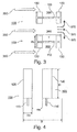
- Fig. 3 shows a top view of the mixing module Fig. 1 , In the plan view in Fig. 3 In addition to the two mixing elements 100, an air flow 350 indicated by three arrows, a mixing region 360, a mixed air flow 370 indicated by three further arrows, a secondary wall width Rv and a distance T of the first auxiliary wall 120 to the second auxiliary wall 130 are shown. From the top view of Fig. 3 opens up an H-shaped floor plan of each mixing element 100 in profile, which is formed respectively by the first auxiliary wall 120, the main wall 110 and the second auxiliary wall 130.
- the airflow 350 which in Fig. 3 From the left edge of the drawing flows in the plane to the right, first meets the first side walls 120 of the two mixing elements 100. The air flow 350 then flows past the first side walls 120 at their side edges and enters the mixing region 360, the air flow 350 has a temperature T o .
- the mixing region 360 also enters the air flow 240 at the temperature T u .
- the airflow 240 is in Fig. 3 Although not shown, but would be in this representation in the mixing area 360 out of the drawing plane in the direction of a viewer of Fig. 3 stream.
- the air flow 240 mixes with the temperature T u and the air flow 350 with the temperature T o .
- the mixing region 360 viewed in the flow direction of the air flow 350, begins at those main surfaces of the first auxiliary walls 120 that face the respective second auxiliary walls 130.
- the mixing area 360 extends as far as the second side walls 130, more precisely up to those main surfaces of the second side walls 130 which face the first side walls 120 or also extend beyond the second side walls 130 to the right in FIG Fig. 3 ,
- the mixing area 360 extends into Fig. 3 also between the mixing elements 100, as well as above and below the same. The exact limits of the mixing area 360 also depend on the geometry of the room in which the mixing module is installed.
- the mixed air flow 370 which is mixed from the air flow 240 and the air flow 350, exits the mixing region 360 in the region of the second auxiliary walls 130 of the mixing elements 100.
- the mixed airflow 370 initially runs along the same direction as the airflow 350.
- the mixed airflow 370 may also change direction after leaving the mixing area 360. For example, the mixed airflow 370 may divide after exiting the mixing area 360 as shown in FIG Fig. 3 is shown.
- the auxiliary wall width Rv and the distance T of the first auxiliary wall 120 to the second auxiliary wall 130 are in Fig. 3 drawn by way of example for the lower mixing element 100, but of course also apply to the upper mixing element 100 in Fig. 3 ,
- the auxiliary wall width Rv corresponds to an extension of a narrow side edge of a first auxiliary wall 120 of a mixing element 100.
- the distance T of the first auxiliary wall 120 to the second auxiliary wall 130 is measured between those main surfaces of the first and second auxiliary wall 120, 130, which are facing away from each other.
- Rv / T ⁇ 0.2 generally applies for a good mixing result in the mixing region 360.
- the ratio is approximately 0.5 and the two mixing elements 100 have substantially the same dimensions and size relationships.
- Fig. 4 shows a front view of the mixing module Fig. 1 ,
- the view in Fig. 4 on the mixing elements 100 of the mixing module takes place along the flow direction of the air flow 350 in Fig. 3 ,
- the main surfaces of the first auxiliary walls 120 facing the air flow 350 as well as lower portions of the narrow sides of the main walls 110 are visible in the illustration.
- the two mixing elements 100 have substantially the same dimensions and proportions.
- In the front view of Fig. 4 On the two illustrated mixing elements 100 further dimensions and size ratios are illustrated.
- a distance Rh between opposite side edges of the first side walls 120 of the two mixing elements 100, a width B of an entire air duct in the space in which the mixing module is installed, and a height H of the first side walls 120 of the mixing elements are shown.
- the height H of the first auxiliary walls 120 of the mixing elements 100 may also correspond to the height of the second auxiliary walls 130.
- the height H corresponds to the extent of a long side edge of a first auxiliary wall 120.
- the width B is in Fig. 4 chosen arbitrarily, since the entire air-carrying channel is not shown.
- the distance Rh need not only apply to the opposite side edges of the first side walls 120, but may also apply to the opposite side edges of the second side walls 130, although the same in FIG Fig. 4 are not shown.
- the secondary wall width Rv drawn drawn.
- the following proportions in the mixing module apply.
- this ratio is approximately 4.
- the secondary wall width Rv is related to the distance Rh here generally according to Rv / Rh ⁇ 0.2. In Fig. 4 this ratio is approximately 1.
- the height H is approximately four times the auxiliary wall width Rv.
Landscapes
- Physics & Mathematics (AREA)
- Thermal Sciences (AREA)
- Engineering & Computer Science (AREA)
- Mechanical Engineering (AREA)
- Chemical & Material Sciences (AREA)
- Dispersion Chemistry (AREA)
- Chemical Kinetics & Catalysis (AREA)
Description
Die vorliegende Erfindung bezieht sich auf ein Klimagerät für zwei sich in dem Klimagerät kreuzende Luftströme, das in einem Fahrzeug eingesetzt werden kann, wie z.B. in
Bei der Entwicklung moderner Klimageräte bzw. Klimaanlagen, insbesondere solchen, die in Fahrzeugen Anwendung finden, stellt sich das Problem, dass immer weniger Bauraum im Fahrzeug für die Klimaanlage (HVAC, Heating, Ventilating, and Air Conditioning; engl. Heizung, Lüftung und Luftkonditionierung) zur Verfügung gestellt wird und gleichzeitig die Anforderungen an die Temperaturregelung/Temperaturschichtung steigen. Um diese Aufgaben zu bewerkstelligen, wird Mischraum bzw. Bauraum im HVAC benötigt, in dem sich kalte und warme Luft vermischen können. Die Temperaturregelung/Schichtung wird in vielen bekannten HVAC mit Hilfe von Luftleitteilen und/oder Kalt- und Warmkanälen erreicht.In the development of modern air conditioners or air conditioning systems, especially those that are used in vehicles, the problem is that less and less space in the vehicle for the air conditioning (HVAC, Heating, Ventilating, and Air Conditioning; Engl. Heating, ventilation and air conditioning ) and at the same time the temperature control / temperature stratification requirements increase. In order to accomplish these tasks, mixing space or installation space in the HVAC is needed, in which cold and warm air can mix. The temperature control / stratification is achieved in many known HVAC with the help of Luftleitteilen and / or cold and warm channels.
Es ist die Aufgabe der vorliegenden Erfindung, ein verbessertes Klimagerät zu schaffen.It is the object of the present invention to provide an improved air conditioning unit.
Diese Aufgabe wird durch ein Klimagerät gemäß den unabhängigen und nebengeordneten Ansprüchen gelöst.This object is achieved by an air conditioner according to the independent and independent claims.
Der vorliegenden Erfindung liegt die Erkenntnis zugrunde, dass sich zwei Luftströme mit unterschiedlichen Temperaturen in kleinem Bauraum optimal durchmischen lassen, wenn ein Mischmodul mit H-förmigem Schnittprofil bzw. ein H-Mischmodul eingesetzt wird. Das Mischmodul umfasst zumindest ein Mischelement zur Verbesserung der Luftdurchmischung in Klimageräten und ist geeignet für zwei Luftströme, die nicht parallel zueinander strömen. Das Mischelement ist mit 2 quasi-parallelen Wänden gebildet, die in der Mitte durch eine Wand verbunden sind, die normal zu beiden Wänden und parallel zu den sich kreuzenden Luftströmungen angeordnet ist. Eine Kontaktfläche zwischen kalter und warmer Luft wird durch derartige Mischelemente um ein vielfaches vergrößert, wodurch die Durchmischung deutlich beschleunigt wird, Das Mischmodul kann z. B. nach dem Heizkörper im Klimagerät eingebaut sein. Gleichzeitig dienen die Mischelemente als Kanäle, um Luft mit einer bestimmten Temperatur ungestört zu führen.The present invention is based on the finding that two air streams with different temperatures in a small space can mix optimally when a mixing module with H-shaped section profile or an H-mixing module is used. The mixing module comprises at least one mixing element for improving the air mixing in air conditioning units and is suitable for two air streams which do not flow parallel to one another. The mixing element is formed with two quasi-parallel walls connected at the center by a wall normal to both walls and parallel to the intersecting air flows. A contact surface between cold and warm air is increased by such mixing elements by a multiple, whereby the mixing is significantly accelerated, the mixing module can, for. B. be installed after the radiator in the air conditioner. At the same time, the mixing elements serve as channels to guide air undisturbed at a certain temperature.
Vorteilhafterweise können durch Verwenden des erfindungsgemäßen Mischmoduls die für Temperaturregelung und Schichtung notwendigen Leitteile und Kanäle im Klimagerät vermieden werden, sodass es nicht zu hohen Druckverlusten und verringerter Leistung bzw. förderbarer Luftmenge einer Klimaanlage kommt. Es wird dadurch auch weniger Bauraum im Fahrzeug für die Klimaanlage benötigt. Die oben genannten Einbauten in Form des Mischmoduls wirken sich hinsichtlich der Akustik positiv aus, sodass Störgeräusche minimiert werden können. Es entfällt die Optimierung von oben genannten Leitteilen, wodurch Entwicklungsaufwand eingespart werden kann, insbesondere im Versuch und der Berechnung. Somit ist eine komplexe Regelung der Anlage ohne hohen Entwicklungsaufwand möglich. Die Entwicklungskosten werden drastisch reduziert. Ferner kann die Temperatursträhnigkeit der Luft an den Kanalauslässen in die Fahrzeugkabine dank des Mischraumes vorteilhaft gelöst werden. Dadurch wird der Komfort für den Passagier positiv beeinflusst, da keine Temperatursträhnigkeit an den Kanalauslässen vorliegt.Advantageously, by using the mixing module according to the invention necessary for temperature control and stratification control parts and channels in the air conditioner can be avoided, so that it does not come to high pressure losses and reduced power or recoverable amount of air conditioning. It also requires less space in the vehicle for the air conditioning. The above-mentioned internals in the form of the mixing module have a positive effect on the acoustics, so that noise can be minimized. It eliminates the optimization of the above-mentioned guiding parts, which development costs can be saved, especially in the trial and the calculation. Thus, a complex control of the system without high development costs is possible. The development costs are drastically reduced. Furthermore, the temperature stretch of the air at the channel outlets into the vehicle cabin can be advantageously solved thanks to the mixing space. Thereby the comfort for the passenger is positively influenced because there is no temperature stretch at the channel outlets.
Die vorliegende Erfindung schafft ein Klimagerät mit einem Mischmodul mit mindestens zwei Mischelementen für zwei sich in einem Klimagerät kreuzende Luftströme, wobei jedes Mischelement folgende Merkmale aufweist:
- eine Hauptwand eines Mischbereichs zum Mischen eines ersten Luftstroms und eines, sich mit dem ersten Luftstrom kreuzenden, zweiten Luftstroms, wobei die Hauptwand so angeordnet ist, dass in Betrieb des Mischelements eine Einströmrichtung des ersten Luftstroms in den Mischbereich und eine Einströmrichtung des zweiten Luftstroms in den Mischbereich längs bezüglich einer Haupterstreckungsebene der Hauptwand verlaufen; und
- eine erste und eine zweite Nebenwand des Mischbereichs, die jeweils mit einer Hauptoberfläche an gegenüberliegenden Seitenkanten der Hauptwand angebracht sind, wobei die erste und die zweite Nebenwand so angeordnet sind, dass in Betrieb des Mischelements die Einströmrichtung des ersten Luftstroms in den Mischbereich an einer Seitenkante der ersten Nebenwand vorbei und quer zu der Hautoberfläche der ersten Nebenwand verläuft, die Einströmrichtung des zweiten Luftstroms in den Mischbereich längs bezüglich der Hauptoberfläche der ersten Nebenwand verläuft, und eine Ausströmrichtung eines aus dem ersten und dem zweiten Luftstrom gemischten Luftstroms aus dem Mischbereich an einer Seitenkante der zweiten Nebenwand vorbei und quer zu der Hauptoberfläche der zweiten Nebenwand verläuft.
- a main wall of a mixing area for mixing a first air flow and a second air flow crossing with the first air flow, wherein the main wall is arranged so that in operation of the mixing element, an inflow direction of the first air flow into the mixing area and an inflow direction of the second air flow in the Blending area run longitudinally with respect to a main plane of extension of the main wall; and
- a first and a second auxiliary wall of the mixing area, each having a main surface attached to opposite side edges of the main wall, wherein the first and second side walls are arranged so that in operation of the mixing element, the inflow direction of the first air flow into the mixing area at a side edge of the the first auxiliary wall extends past and across the skin surface of the first auxiliary wall, the inflow direction of the second air flow extends into the mixing region longitudinally with respect to the main surface of the first auxiliary wall, and an outflow direction of an air flow mixed from the first and second air currents out of the mixing region at a side edge of the first second auxiliary wall passes and transverse to the main surface of the second secondary wall.
Unter einem Klimagerät kann hierbei eine Klimaanlage bzw. eine Anlage zur Heizung. Lüftung und Luftkonditionierung (HVAC, engl. Heating, Ventilating, and Air Conditioning) verstanden werden, wie sie beispielsweise in einem Fahrzeug zum Einsatz kommt. In einem derartigen Klimagerät können Luftströme unterschiedlicher Temperaturen erzeugt und geführt werden. Hier sind dies ein erster und ein zweiter Luftstrom. Die Luftströme können so geführt werden, dass sie sich an einer Stelle in dem Klimagerät kreuzen. An dieser Kreuzungsstelle, die einen Mischbereich der Luftströme darstellt, ist das Mischelement angeordnet. Das Mischelement umfasst die Hauptwand und die beiden Nebenwände. Ein Schnittprofil durch die Hauptwand und die Nebenwände des Mischelements kann im Wesentlichen H-förmig sein. Die Einströmrichtungen der beiden Luftströme in Betrieb des Mischelements spannen die Haupterstreckungsebene der Hauptwand auf. Dabei können die Einströmrichtungen durch entsprechend angeordnete und ausgeformte Eintrittsöffnungen oder Führungskanäle für die Luftströme vorgegeben sein. Eine Form des Mischelements kann an eine Geometrie des Raums angepasst sein, in dem das Mischelement zur Verbauung vorgesehen ist. Insbesondere gilt dies für die Seitenkanten der Hauptwand, an denen keine Nebenwände angebracht sind, sowie für die gesamte Dimensionierung des Mischelements. Kanten der Hauptwand und der Nebenwände können einen geraden, gekrümmten oder eine Mischung aus einem geraden und gekrümmten Verlauf aufweisen, beispielsweise einen stufenund/oder bogenförmigen Verlauf.Under an air conditioner can here an air conditioner or a system for heating. Ventilation and air conditioning (HVAC, engl. Heating, Ventilating, and Air Conditioning) are understood, as used for example in a vehicle. In such an air conditioner air streams of different temperatures can be generated and performed. Here these are a first and a second airflow. The air streams can be guided in this way that they intersect at a point in the air conditioner. At this intersection, which represents a mixing region of the air flows, the mixing element is arranged. The mixing element comprises the main wall and the two auxiliary walls. A sectional profile through the main wall and the side walls of the mixing element may be substantially H-shaped. The inflow directions of the two air streams in operation of the mixing element span the main extension plane of the main wall. In this case, the inflow directions can be predetermined by correspondingly arranged and shaped inlet openings or guide channels for the air streams. A shape of the mixing element may be adapted to a geometry of the space in which the mixing element is provided for obstruction. In particular, this applies to the side edges of the main wall to which no auxiliary walls are attached, and for the entire dimensioning of the mixing element. Edges of the main wall and the auxiliary walls may have a straight, curved or a mixture of a straight and curved course, for example a stepped and / or curved course.
Hierbei kann die Hauptwand des Mischbereichs auf beiden Seiten ihrer Haupterstreckungsebene von dem ersten und dem zweiten Luftstrom umströmbar sein. Die Hauptwand ist somit in dem Mischbereich angeordnet. Beide ihrer Hauptoberflächen können von den beiden Luftströmen berührt werden. Dies bietet den Vorteil, dass die Vermischung des ersten und des zweiten Luftstroms effizienter erfolgen kann, da auf beiden Seiten der Hauptwand der Mischbereich zur Verfügung steht.In this case, the main wall of the mixing area can be flowed around on both sides of its main extension plane of the first and the second air flow. The main wall is thus arranged in the mixing area. Both of their main surfaces can be touched by the two air streams. This offers the advantage that the mixing of the first and the second air stream can be carried out more efficiently, since the mixing zone is available on both sides of the main wall.
Ferner können eine Seitenkante der ersten Nebenwand und eine Seitenkante der zweiten Nebenwand einen Überstand über die Haupterstreckungsebene der Hauptwand aufweisen. Der Überstand über die Haupterstreckungsebene der Hauptwand kann bei der ersten und der zweiten Nebenwand den gleichen Betrag aufweisen. Der Überstand kann von beiden Hauptoberflächen der Hauptwand aus betrachtet vorliegen. Durch den Überstand stehen Seitenkanten der Nebenwände über jeweilige Hauptoberflächen der Hauptwand vor. Dies bietet den Vorteil, dass die Durchmischung der beiden Luftströme weiter verbessert wird. So können durch die von den Hauptoberflächen der Hauptwand vorstehenden Nebenwände Luftverwirbelungen entstehen, die eine Vermischung der Luftströme begünstigen.Furthermore, a side edge of the first auxiliary wall and a side edge of the second auxiliary wall may have a projection over the main extension plane of the main wall. The projection over the main extension plane of the main wall may have the same amount in the first and the second auxiliary wall. The supernatant can be viewed from both main surfaces of the main wall. By the projection stand side edges of the auxiliary walls on respective main surfaces of the main wall. This offers the advantage that the mixing of the two air streams is further improved. Thus, the turbulence caused by the main surfaces of the main wall projecting auxiliary walls air turbulence, which favor a mixing of the air streams.
Gemäß einer Ausführungsform können sich die erste und die zweite Nebenwand jeweils über mindestens eine halbe Länge der Seitenkante der Hauptwand erstrecken, an der sie angebracht sind. Mindestens die halbe Länge kann hier insbesondere annähernd die ganze Länge bedeuten. Dies bietet den Vorteil, dass die Vermischung der Luftströme über die gesamte Höhe des Mischbereichs durch die von den Nebenwänden bewirkten Verwirbelungen unterstützt wird und somit effizienter wird.According to one embodiment, the first and the second auxiliary wall each extend over at least a half length of the side edge of the main wall to which they are attached. At least half the length can mean here in particular approximately the entire length. This has the advantage that the mixing of the air streams over the entire height of the mixing area is supported by the turbulence caused by the secondary walls and thus becomes more efficient.
So kann eine Breite einer der Nebenwände höchstens ein Fünftel eines Abstands zwischen der ersten und der zweiten Nebenwand betragen. Diese Bedingung kann für beide Nebenwände gelten. Bei der Breite einer der Nebenwände handelt es sich um den Abstand zwischen den beiden Seitenkanten der Nebenwand, an denen der erste Luftstrom vorbeiströmt. Dies bietet den Vorteil, dass sich bei diesem Abmessungsverhältnis eine sehr gute Durchmischung und Verwirbelung der Luftströme ergibt.Thus, a width of one of the auxiliary walls can amount to at most one fifth of a distance between the first and the second auxiliary wall. This condition can apply to both auxiliary walls. The width of one of the auxiliary walls is the distance between the two side edges of the auxiliary wall where the first airflow passes. This offers the advantage that with this dimensional ratio a very good mixing and turbulence of the air flows results.
In dem Mischmodul werden erfindungsgemäße Mischelemente vorteilhaft eingesetzt.In the mixing module mixing elements according to the invention are advantageously used.
Hierbei können die Hauptwände der mindestens zwei Mischelemente einander gegenüberliegend und voneinander beabstandet angeordnet sein, wobei die Haupterstreckungsebenen der Hauptwände eine gemeinsame Ausrichtung aufweisen können. Die Haupterstreckungsebenen der Hauptwände der mindestens zwei Mischelemente können hierbei im Wesentlichen bzw. annähernd parallel zueinander verlaufen. So kann die Anordnung eines der mindestens zwei Mischelemente bezüglich eines anderen der mindestens zwei Mischelemente durch eine Verschiebung des einen zu dem anderen Mischelement in eine Richtung beschrieben sein, die annähernd orthogonal zu den Haupterstreckungsebenen ihrer Hauptwände ist. Dies bietet den Vorteil, dass durch diese Anordnung der mindestens zwei Mischelemente eine Durchmischung der zwei Luftströme weiter optimiert wird.Here, the main walls of the at least two mixing elements may be arranged opposite each other and spaced from each other, wherein the main extension planes of the main walls may have a common orientation. The main extension levels of the main walls of the at least two mixing elements can in this case substantially or approximately parallel to each other. Thus, the arrangement of one of the at least two mixing elements with respect to another of the at least two mixing elements may be described by a displacement of the one to the other mixing element in a direction which is approximately orthogonal to the main extension planes of their main walls. This offers the advantage that a further mixing of the two air streams is further optimized by this arrangement of the at least two mixing elements.
Ferner kann ein Abstand zwischen gegenüberliegenden Seitenkanten der Nebenwände benachbarter Mischelemente der mindestens zwei Mischelemente höchstens das Fünffache einer Breite einer Nebenwand betragen. Durch diese Bedingung an das Größenverhältnis kann die Vermischung der zwei Luftströme noch weiter verbessert werden.Furthermore, a distance between opposite side edges of the secondary walls of adjacent mixing elements of the at least two mixing elements can amount to at most five times a width of an auxiliary wall. By this condition to the size ratio, the mixing of the two air streams can be further improved.
Die vorliegende Erfindung schafft ferner ein Klimagerät, das folgende Merkmale aufweist:
- einen Vermischungsraum für zwei sich in dem Vermischungsraum kreuzende Luftströme;
- einen ersten Eintrittskanal für einen ersten Luftstrom, der an einer ersten Seite in den Vermischungsraum einmündend angeordnet ist;
- einen zweiten Eintrittskanal für einen zweiten Luftstrom, der an einer an die erste Seite angrenzenden Bodenseite in den Vermischungsraum einmündend angeordnet ist;
- einen Austrittskanal für einen gemischten Luftstrom, der an einer zweiten Seite gegenüber der ersten Seite aus dem Vermischungsraum austretend angeordnet ist; und
- ein erfindungsgemäßes Mischmodul, das in dem Vermischungsraum angeordnet ist, wobei in dem Mischmodul der erste und der zweite Luftstrom von den Eintrittskanälen mischbar sind und der gemischte Luftstrom in den Austrittskanal ausgebbar ist.
- a mixing space for two air streams crossing in the mixing space;
- a first inlet channel for a first air stream, which is arranged at a first side merging into the mixing space;
- a second inlet channel for a second air stream, which is arranged at a side adjacent to the first side bottom side merging into the mixing space;
- a mixed airflow exit channel disposed at a second side opposite the first side from the mixing space; and
- a mixing module according to the invention, which is arranged in the mixing space, wherein in the mixing module of the first and the second air flow from the inlet channels are miscible and the mixed air flow can be output into the outlet channel.
Bei dem Vermischungsraum kann es sich um den Bauraum in dem Klimagerät handeln, in dem das Mischmodul einbaubar ist. Die Form des Vermischungsraums kann von den baulichen Gegebenheiten des Klimageräts vorgegeben sein. Der erste und der zweite Eintrittskanal sowie der Austrittskanal sind an unterschiedlichen Seiten des Vermischungsraums angeordnet. Die Seite des ersten Eintrittskanals und die gegenüberliegende Seite des Austrittskanals können beide an die Bodenseite mit dem zweiten Eintrittskanal angrenzen.The mixing space can be the installation space in the air conditioning unit in which the mixing module can be installed. The shape of the mixing room can be predetermined by the structural conditions of the air conditioner. The first and the second inlet channel and the outlet channel are arranged on different sides of the mixing space. The side of the first inlet channel and the opposite side of the outlet channel can both adjoin the bottom side with the second inlet channel.
Hierbei kann der Abstand zwischen gegenüberliegenden Seitenkanten der Nebenwände der zwei Mischelemente des Mischmoduls höchstens ein Drittel einer Abmessung des Vermischungsraums in der Richtung dieses Abstands betragen. Dies bietet den Vorteil, dass durch diese Bedingung an das Größenverhältnis die Vermischung der zwei Luftströme optimiert werden kann.Here, the distance between opposite side edges of the auxiliary walls of the two mixing elements of the mixing module can be at most one third of a dimension of the mixing space in the direction of this distance. This offers the advantage that by this condition to the size ratio, the mixing of the two air streams can be optimized.
Vorteilhafte Ausfüllrungsbeispiele der vorliegenden Erfindung werden nachfolgend Bezug nehmend auf die beiliegenden Zeichnungen näher erläutert. Es zeigen:
- Fig. 1
- eine isometrische Ansicht eines Mischmoduls mit zwei Mischelementen. gemäß einem Ausführungsbeispiel der vorliegenden Erfindung;
- Fig. 2
- eine Seitenansicht eines der Mischelemente des Mischmoduls aus
Fig. 1 ; - Fig. 3
- eine Draufsicht des Mischmoduls aus
Fig. 1 ; und - Fig. 4
- eine Vorderansicht des Mischmoduls aus
Fig. 1 .
- Fig. 1
- an isometric view of a mixing module with two mixing elements. according to an embodiment of the present invention;
- Fig. 2
- a side view of one of the mixing elements of the mixing module
Fig. 1 ; - Fig. 3
- a top view of the mixing module
Fig. 1 ; and - Fig. 4
- a front view of the mixing module
Fig. 1 ,
In der nachfolgenden Beschreibung der bevorzugten Ausführungsbeispiele der vorliegenden Erfindung werden für die in den verschiedenen Zeichnungen dargestellten und ähnlich wirkenden Elemente gleiche oder ähnliche Bezugszeichen verwendet, wobei eine wiederholte Beschreibung dieser Elemente weggelassen wird.In the following description of the preferred embodiments of the present invention, the same or similar reference numerals are used for the elements shown in the various drawings and similar, and a repeated description of these elements will be omitted.
Die Hauptwand 110 des Mischelements 100 ist ein plattenförmiger Körper. Die Hauptwand 110 weist somit zwei Hauptoberflächen auf. Ein Grundriss der Hauptwand 110 ist von asymmetrischer Form. In
Die erste Nebenwand 120 ist in
Die zweite Nebenwand 130 weist in
Die zwei Mischelemente 100, die das Mischmodul aufweist, sind relativ zueinander so angeordnet, dass sich Hauptoberflächen der Hauptwände 110 der Mischelemente 100 gegenüberliegen. Die Mischelemente 100 sind entlang einer Richtung voneinander beabstandet, die orthogonal zu den Haupterstreckungsebenen der Hauptwände 110 der Mischelement 100 verläuft. In
Die Formen, Abmessungen und Anordnungen von Elementen, die in diesem Ausführungsbeispiel beschrieben sind, sind lediglich exemplarisch und es können weitere Ausführungsbeispiele davon abweichende Formen, Abmessungen und Anordnungen von Elementen aufweisen, je nach der Geometrie des Bauraums, in dem das Mischmodul zu verbauen ist.The shapes, dimensions and arrangements of elements described in this embodiment are merely exemplary and further embodiments thereof may have different shapes, dimensions and arrangements of elements depending on the geometry of the construction space in which the mixing module is to be installed.
Folglich ist die jeweilige Krümmung der beiden Hauptwände 120,130 erkennbar.Consequently, the respective curvature of the two main walls 120,130 can be seen.
Die Hauptwand 110 weist vier Umfangskanten auf, einen Umriss der Hauptwand 110 darstellen. Die obere Kante der Hauptwand 110 weist den stufenförmigen Verlauf auf, wobei die Stufen unterschiedliche Höhen und Längen aufweisen. In
Die erste und die zweite Nebenwand 120, 130 sind den jeweils angrenzenden Seitenkanten der Hauptwand 110 entsprechend im Längsprofil gebogen bzw. gekrümmt. Das Längsprofil der ersten Nebenwand 120 folgt dem Verlauf der angrenzenden, in
Der Luftstrom 350, der in
In den Mischbereich 360 tritt ebenfalls der Luftstrom 240 mit der Temperatur Tu ein. Der Luftstrom 240 ist in
Der gemischte Luftstrom 370, der aus dem Luftstrom 240 und dem Luftstrom 350 gemischt ist, tritt im Bereich der zweiten Nebenwände 130 der Mischelemente 100 aus dem Mischbereich 360 aus. Der gemischte Luftstrom 370 verläuft zunächst entlang der gleichen Richtung wie der Luftstrom 350. Abhängig von der Geometrie des Raumes, in dem das Mischmodul verbaut ist, kann der gemischte Luftstrom 370 nach Verlassen des Mischbereichs 360 auch seine Richtung ändern. Beispielsweise kann der gemischte Luftstrom 370 sich nach Verlassen des Mischbereichs 360 aufteilen, wie es in
Die Nebenwandbreite Rv und der Abstand T der ersten Nebenwand 120 zu der zweiten Nebenwand 130 sind in
So sind in
Für ein optimales Mischergebnis der beiden Luftströme gelten folgende Größenverhältnisse im Mischmodul. So gelte für die Beziehung zwischen der Breite B des gesamten Luft führenden Kanals und dem Abstand Rh im Allgemeinen das Verhältnis B/Rh ≥ 3. In
Die beschriebenen Ausführungsbeispiele sind nur beispielhaft gewählt und können miteinander kombiniert werden. Auch können Ausführungsbeispiele der vorliegenden Erfindung nur Teile der in den Figuren gezeigten Elemente aufweisen. The described embodiments are chosen only by way of example and can be combined with each other. Also, embodiments of the present invention may include only parts of the elements shown in the figures.
Claims (8)
- An air conditioner which comprises the following features:a mixing space for two airflows (240, 350) intersecting in the mixing space;a first inlet duct for a first air flow (350), which is arranged so as to lead into the mixing space on a first side;a second inlet duct for a second air flow (240), which is arranged so as to lead into the mixing space on a bottom side adjoining the first side;an outlet duct for a mixed air flow (370), which is arranged so as to lead out of the mixing space on a second side opposite the first side; anda mixing module for two air flows (240, 350) intersecting in an air conditioner being provided, wherein the mixing module has at least two mixing elements (100), wherein the mixing module is arranged in the mixing space, wherein the first and the second air flow (240, 350) from the inlet ducts can be mixed in the mixing module and the mixed air flow (370) can be discharged into the outlet duct, wherein a mixing element (100) for two air flows intersecting in an air conditioner is formed, wherein the mixing element (100) comprises the following features:a main wall (110) of a mixing region (360) for mixing a first air flow (350) and a second air flow (240) intersecting the first air flow (350), the main wall (110) being arranged such that in operation of the mixing element (100) an inflow direction of the first air flow (350) into the mixing region (360) and an inflow direction of the second air flow (240) into the mixing region (360) run longitudinally with respect to a main extension plane of the main wall (110); anda first and a second auxiliary wall (120, 130) of the mixing region (360) which are in each case mounted with a main surface on opposite side edges of the main wall (110), the first and the second auxiliary wall (120, 130) being arranged such that in operation of the mixing element (100) the inflow direction of the first air flow (350) into the mixing region (360) runs past a side edge of the first auxiliary wall (120) and transversely with respect to the main surface of the first auxiliary wall (120), the inflow direction of the second air flow (240) into the mixing region (360) runs longitudinally with respect to the main surface of the first auxiliary wall (120), and an outflow direction of an air flow (370) mixed from the first and the second air flow (240, 350) out of the mixing region (360) runs past a side edge of the second auxiliary wall (130) and transversely with respect to the main surface of the second auxiliary wall (130).
- The air conditioner as claimed in claim 1, wherein the first and the second air flow (240, 350) can flow around the main wall (110) of the mixing region (360) on both sides of its main extension plane.
- The air conditioner as claimed in one of the preceding claims, wherein a side edge of the first auxiliary wall (120) and a side edge of the second auxiliary wall (130) have a projection beyond the main extension plane of the main wall (110).
- The air conditioner as claimed in one of the preceding claims, wherein the first and the second auxiliary wall (120, 130) extend in each case over at least half a length of the side edge of the main wall (110) on which they are mounted.
- The air conditioner as claimed in one of the preceding claims, wherein a width (Rv) of one of the auxiliary walls (120, 130) is at most a fifth of a spacing (T) between the first and the second auxiliary wall (120, 130).
- The air conditioner as claimed in one of claims 1 to 5, wherein the main walls (110) of the at least two mixing elements (100) are arranged opposite and spaced apart from one another, the main extension planes of the main walls (110) having a common orientation.
- The air conditioner as claimed in claim 6, wherein a spacing (Rh) between opposite side edges of the auxiliary walls (120, 130) of adjacent mixing elements (100) of the at least two mixing elements (100) is at most five times a width (Rv) of an auxiliary wall (120, 130).
- The air conditioner as claimed in one of claims 1 to 7, wherein the spacing (Rh) between opposite side edges of the auxiliary walls (120, 130) of the two mixing elements (100) of the mixing module is at most a third of a dimension (B) of the mixing space in the direction of this spacing (Rh).
Applications Claiming Priority (2)
| Application Number | Priority Date | Filing Date | Title |
|---|---|---|---|
| DE102010041282A DE102010041282A1 (en) | 2010-09-23 | 2010-09-23 | Mixing element and mixing module for two air streams crossing in an air conditioner |
| PCT/EP2011/065349 WO2012038246A1 (en) | 2010-09-23 | 2011-09-06 | Mixing element and mixing module for two air flows intersecting in an air conditioner |
Publications (2)
| Publication Number | Publication Date |
|---|---|
| EP2619022A1 EP2619022A1 (en) | 2013-07-31 |
| EP2619022B1 true EP2619022B1 (en) | 2016-04-06 |
Family
ID=44583035
Family Applications (1)
| Application Number | Title | Priority Date | Filing Date |
|---|---|---|---|
| EP11754369.4A Not-in-force EP2619022B1 (en) | 2010-09-23 | 2011-09-06 | Mixing element and mixing module for two air flows intersecting in an air conditioner |
Country Status (5)
| Country | Link |
|---|---|
| US (1) | US9550155B2 (en) |
| EP (1) | EP2619022B1 (en) |
| CN (1) | CN103153658B (en) |
| DE (1) | DE102010041282A1 (en) |
| WO (1) | WO2012038246A1 (en) |
Families Citing this family (2)
| Publication number | Priority date | Publication date | Assignee | Title |
|---|---|---|---|---|
| DE102012211669A1 (en) * | 2012-07-04 | 2014-01-09 | Behr Gmbh & Co. Kg | air conditioning |
| FR3050143A1 (en) * | 2016-04-19 | 2017-10-20 | Valeo Systemes Thermiques | PLASTIC COMPONENT FOR HEATING, VENTILATION OR AIR CONDITIONING DEVICE |
Family Cites Families (15)
| Publication number | Priority date | Publication date | Assignee | Title |
|---|---|---|---|---|
| US993242A (en) * | 1903-09-11 | 1911-05-23 | American Universal Mill Company | Solid-rolled cross-sectionally-h-shaped metal bar or structural section. |
| US1554108A (en) * | 1923-03-03 | 1925-09-15 | Jones & Laughlin Steel Corp | Metal beam |
| DE3817215C1 (en) * | 1988-05-17 | 1989-07-13 | Wolf Klimatechnik Gmbh, 8302 Mainburg, De | Mixing-air part for a mixing chamber of a ventilation or air-conditioning installation |
| FI91319C (en) * | 1993-04-23 | 1994-06-10 | Flaekt Oy | Mixing section between supply air and return air of the air conditioning system |
| DE4416343C2 (en) * | 1994-05-09 | 1996-10-17 | Karlsruhe Forschzent | Static micro mixer |
| US5520459A (en) * | 1994-06-30 | 1996-05-28 | The United States Of America As Represented By The Secretary Of The Navy | Enhancement of flow mixing by a frequency tunable cavity |
| FR2735723B1 (en) | 1995-06-21 | 1997-08-01 | Valeo Climatisation | DEVICE FOR HEATING-VENTILATION OF THE INTERIOR OF A MOTOR VEHICLE |
| DE19541266A1 (en) * | 1995-11-06 | 1997-05-07 | Bayer Ag | Method and device for carrying out chemical reactions using a microstructure lamella mixer |
| DE19703779C2 (en) * | 1997-02-01 | 2003-06-05 | Karlsruhe Forschzent | Method and device for producing a disperse mixture |
| JP4396014B2 (en) * | 2000-06-06 | 2010-01-13 | 株式会社デンソー | Air conditioner |
| JP4172013B2 (en) * | 2003-02-10 | 2008-10-29 | 株式会社ヴァレオサーマルシステムズ | Automotive air conditioner |
| JP4045215B2 (en) * | 2003-07-14 | 2008-02-13 | 株式会社ケーヒン | Air conditioner for vehicles |
| JP2006137295A (en) * | 2004-11-12 | 2006-06-01 | Mitsubishi Heavy Ind Ltd | Air conditioner for vehicle |
| FR2889486B1 (en) | 2005-08-03 | 2011-05-27 | Valeo Systemes Thermiques | DEVICE FOR DISTRIBUTING AN AIR FLOW FOR A HEATING, VENTILATION AND / OR AIR CONDITIONING INSTALLATION FOR A MOTOR VEHICLE AND CORRESPONDING INSTALLATION. |
| CN201348345Y (en) | 2009-01-21 | 2009-11-18 | 奇瑞汽车股份有限公司 | Novel automobile air conditioner multi-zone HVAC device |
-
2010
- 2010-09-23 DE DE102010041282A patent/DE102010041282A1/en not_active Withdrawn
-
2011
- 2011-09-06 WO PCT/EP2011/065349 patent/WO2012038246A1/en active Application Filing
- 2011-09-06 US US13/825,645 patent/US9550155B2/en active Active
- 2011-09-06 CN CN201180045769.XA patent/CN103153658B/en not_active Expired - Fee Related
- 2011-09-06 EP EP11754369.4A patent/EP2619022B1/en not_active Not-in-force
Also Published As
| Publication number | Publication date |
|---|---|
| CN103153658B (en) | 2015-07-22 |
| US20130250718A1 (en) | 2013-09-26 |
| US9550155B2 (en) | 2017-01-24 |
| EP2619022A1 (en) | 2013-07-31 |
| CN103153658A (en) | 2013-06-12 |
| DE102010041282A1 (en) | 2012-03-29 |
| WO2012038246A1 (en) | 2012-03-29 |
Similar Documents
| Publication | Publication Date | Title |
|---|---|---|
| DE102016216019A1 (en) | Insert for a cooling jacket of an electrical machine | |
| EP2508815B1 (en) | Device for influencing a flow of air in a component of an air conditioning assembly | |
| DE102015119863A1 (en) | Electric heating device for heating fluids | |
| DE112019002399T5 (en) | FLUID DISPENSER | |
| DE202021101741U1 (en) | Flat duct arrangement for a downdraft extractor hood | |
| EP2423016B1 (en) | Device for mixing two air flows | |
| DE102011011710A1 (en) | Air mixing and distribution device and vehicle heating or air conditioning system | |
| EP2619022B1 (en) | Mixing element and mixing module for two air flows intersecting in an air conditioner | |
| DE3217803C2 (en) | Installation part for a mixing chamber of a ventilation and air conditioning system | |
| EP2201639B1 (en) | Battery module | |
| EP3285017A1 (en) | Heating and cooling sail with at least one ventilator | |
| DE102006008218B4 (en) | Compact heating, ventilation and air conditioning system in flat design for motor vehicles | |
| EP0303850B1 (en) | Air-mixing device | |
| DE102005050881B3 (en) | Ventilation device for vehicle interior has components with different lamella structures passing air through them at different opening angles | |
| EP0816772B1 (en) | Air outlet | |
| EP2141429B1 (en) | Hybrid cooling tower | |
| DE102006022088A1 (en) | Air conditioning system for passenger compartment of vehicle, has control devices controlling quantity of cold and warm air, and separation units extending in flow direction of warm air flow and cold air flow | |
| EP1561615B1 (en) | Heat exchanging device | |
| EP1243870A2 (en) | Radiator | |
| DE102007043272B4 (en) | Use for a sanitary fitting | |
| DE202009011733U1 (en) | Device for temperature control, in particular air cooling of a plurality of objects, in particular single batteries of a power supply unit for motor vehicles | |
| DE102017127830B3 (en) | Fluid mixer with staggered Fluidkanalauslass, combustion chamber and aircraft with a fluid mixer | |
| EP3390193A1 (en) | Air-conditioning channel for a rail vehicle, comprising a heating element | |
| AT519365B1 (en) | energy storage | |
| DE102022113854A1 (en) | Heat exchanger for a vehicle |
Legal Events
| Date | Code | Title | Description |
|---|---|---|---|
| PUAI | Public reference made under article 153(3) epc to a published international application that has entered the european phase |
Free format text: ORIGINAL CODE: 0009012 |
|
| 17P | Request for examination filed |
Effective date: 20130423 |
|
| AK | Designated contracting states |
Kind code of ref document: A1 Designated state(s): AL AT BE BG CH CY CZ DE DK EE ES FI FR GB GR HR HU IE IS IT LI LT LU LV MC MK MT NL NO PL PT RO RS SE SI SK SM TR |
|
| DAX | Request for extension of the european patent (deleted) | ||
| RAP1 | Party data changed (applicant data changed or rights of an application transferred) |
Owner name: MAHLE BEHR GMBH & CO. KG |
|
| GRAP | Despatch of communication of intention to grant a patent |
Free format text: ORIGINAL CODE: EPIDOSNIGR1 |
|
| INTG | Intention to grant announced |
Effective date: 20151005 |
|
| GRAS | Grant fee paid |
Free format text: ORIGINAL CODE: EPIDOSNIGR3 |
|
| GRAA | (expected) grant |
Free format text: ORIGINAL CODE: 0009210 |
|
| AK | Designated contracting states |
Kind code of ref document: B1 Designated state(s): AL AT BE BG CH CY CZ DE DK EE ES FI FR GB GR HR HU IE IS IT LI LT LU LV MC MK MT NL NO PL PT RO RS SE SI SK SM TR |
|
| REG | Reference to a national code |
Ref country code: GB Ref legal event code: FG4D Free format text: NOT ENGLISH |
|
| REG | Reference to a national code |
Ref country code: AT Ref legal event code: REF Ref document number: 787340 Country of ref document: AT Kind code of ref document: T Effective date: 20160415 Ref country code: CH Ref legal event code: EP |
|
| REG | Reference to a national code |
Ref country code: IE Ref legal event code: FG4D Free format text: LANGUAGE OF EP DOCUMENT: GERMAN |
|
| REG | Reference to a national code |
Ref country code: DE Ref legal event code: R096 Ref document number: 502011009358 Country of ref document: DE |
|
| REG | Reference to a national code |
Ref country code: LT Ref legal event code: MG4D Ref country code: NL Ref legal event code: MP Effective date: 20160406 |
|
| REG | Reference to a national code |
Ref country code: FR Ref legal event code: PLFP Year of fee payment: 6 |
|
| PG25 | Lapsed in a contracting state [announced via postgrant information from national office to epo] |
Ref country code: NL Free format text: LAPSE BECAUSE OF FAILURE TO SUBMIT A TRANSLATION OF THE DESCRIPTION OR TO PAY THE FEE WITHIN THE PRESCRIBED TIME-LIMIT Effective date: 20160406 |
|
| PG25 | Lapsed in a contracting state [announced via postgrant information from national office to epo] |
Ref country code: FI Free format text: LAPSE BECAUSE OF FAILURE TO SUBMIT A TRANSLATION OF THE DESCRIPTION OR TO PAY THE FEE WITHIN THE PRESCRIBED TIME-LIMIT Effective date: 20160406 Ref country code: IS Free format text: LAPSE BECAUSE OF FAILURE TO SUBMIT A TRANSLATION OF THE DESCRIPTION OR TO PAY THE FEE WITHIN THE PRESCRIBED TIME-LIMIT Effective date: 20160806 Ref country code: PL Free format text: LAPSE BECAUSE OF FAILURE TO SUBMIT A TRANSLATION OF THE DESCRIPTION OR TO PAY THE FEE WITHIN THE PRESCRIBED TIME-LIMIT Effective date: 20160406 Ref country code: LT Free format text: LAPSE BECAUSE OF FAILURE TO SUBMIT A TRANSLATION OF THE DESCRIPTION OR TO PAY THE FEE WITHIN THE PRESCRIBED TIME-LIMIT Effective date: 20160406 Ref country code: NO Free format text: LAPSE BECAUSE OF FAILURE TO SUBMIT A TRANSLATION OF THE DESCRIPTION OR TO PAY THE FEE WITHIN THE PRESCRIBED TIME-LIMIT Effective date: 20160706 |
|
| PG25 | Lapsed in a contracting state [announced via postgrant information from national office to epo] |
Ref country code: ES Free format text: LAPSE BECAUSE OF FAILURE TO SUBMIT A TRANSLATION OF THE DESCRIPTION OR TO PAY THE FEE WITHIN THE PRESCRIBED TIME-LIMIT Effective date: 20160406 Ref country code: RS Free format text: LAPSE BECAUSE OF FAILURE TO SUBMIT A TRANSLATION OF THE DESCRIPTION OR TO PAY THE FEE WITHIN THE PRESCRIBED TIME-LIMIT Effective date: 20160406 Ref country code: LV Free format text: LAPSE BECAUSE OF FAILURE TO SUBMIT A TRANSLATION OF THE DESCRIPTION OR TO PAY THE FEE WITHIN THE PRESCRIBED TIME-LIMIT Effective date: 20160406 Ref country code: SE Free format text: LAPSE BECAUSE OF FAILURE TO SUBMIT A TRANSLATION OF THE DESCRIPTION OR TO PAY THE FEE WITHIN THE PRESCRIBED TIME-LIMIT Effective date: 20160406 Ref country code: HR Free format text: LAPSE BECAUSE OF FAILURE TO SUBMIT A TRANSLATION OF THE DESCRIPTION OR TO PAY THE FEE WITHIN THE PRESCRIBED TIME-LIMIT Effective date: 20160406 Ref country code: GR Free format text: LAPSE BECAUSE OF FAILURE TO SUBMIT A TRANSLATION OF THE DESCRIPTION OR TO PAY THE FEE WITHIN THE PRESCRIBED TIME-LIMIT Effective date: 20160707 Ref country code: PT Free format text: LAPSE BECAUSE OF FAILURE TO SUBMIT A TRANSLATION OF THE DESCRIPTION OR TO PAY THE FEE WITHIN THE PRESCRIBED TIME-LIMIT Effective date: 20160808 |
|
| PG25 | Lapsed in a contracting state [announced via postgrant information from national office to epo] |
Ref country code: IT Free format text: LAPSE BECAUSE OF FAILURE TO SUBMIT A TRANSLATION OF THE DESCRIPTION OR TO PAY THE FEE WITHIN THE PRESCRIBED TIME-LIMIT Effective date: 20160406 |
|
| REG | Reference to a national code |
Ref country code: DE Ref legal event code: R097 Ref document number: 502011009358 Country of ref document: DE |
|
| PG25 | Lapsed in a contracting state [announced via postgrant information from national office to epo] |
Ref country code: RO Free format text: LAPSE BECAUSE OF FAILURE TO SUBMIT A TRANSLATION OF THE DESCRIPTION OR TO PAY THE FEE WITHIN THE PRESCRIBED TIME-LIMIT Effective date: 20160406 Ref country code: CZ Free format text: LAPSE BECAUSE OF FAILURE TO SUBMIT A TRANSLATION OF THE DESCRIPTION OR TO PAY THE FEE WITHIN THE PRESCRIBED TIME-LIMIT Effective date: 20160406 Ref country code: SK Free format text: LAPSE BECAUSE OF FAILURE TO SUBMIT A TRANSLATION OF THE DESCRIPTION OR TO PAY THE FEE WITHIN THE PRESCRIBED TIME-LIMIT Effective date: 20160406 Ref country code: DK Free format text: LAPSE BECAUSE OF FAILURE TO SUBMIT A TRANSLATION OF THE DESCRIPTION OR TO PAY THE FEE WITHIN THE PRESCRIBED TIME-LIMIT Effective date: 20160406 Ref country code: EE Free format text: LAPSE BECAUSE OF FAILURE TO SUBMIT A TRANSLATION OF THE DESCRIPTION OR TO PAY THE FEE WITHIN THE PRESCRIBED TIME-LIMIT Effective date: 20160406 |
|
| PLBE | No opposition filed within time limit |
Free format text: ORIGINAL CODE: 0009261 |
|
| STAA | Information on the status of an ep patent application or granted ep patent |
Free format text: STATUS: NO OPPOSITION FILED WITHIN TIME LIMIT |
|
| PG25 | Lapsed in a contracting state [announced via postgrant information from national office to epo] |
Ref country code: BE Free format text: LAPSE BECAUSE OF NON-PAYMENT OF DUE FEES Effective date: 20160930 Ref country code: SM Free format text: LAPSE BECAUSE OF FAILURE TO SUBMIT A TRANSLATION OF THE DESCRIPTION OR TO PAY THE FEE WITHIN THE PRESCRIBED TIME-LIMIT Effective date: 20160406 |
|
| 26N | No opposition filed |
Effective date: 20170110 |
|
| PG25 | Lapsed in a contracting state [announced via postgrant information from national office to epo] |
Ref country code: MC Free format text: LAPSE BECAUSE OF FAILURE TO SUBMIT A TRANSLATION OF THE DESCRIPTION OR TO PAY THE FEE WITHIN THE PRESCRIBED TIME-LIMIT Effective date: 20160406 |
|
| REG | Reference to a national code |
Ref country code: CH Ref legal event code: PL |
|
| GBPC | Gb: european patent ceased through non-payment of renewal fee |
Effective date: 20160906 |
|
| PG25 | Lapsed in a contracting state [announced via postgrant information from national office to epo] |
Ref country code: SI Free format text: LAPSE BECAUSE OF FAILURE TO SUBMIT A TRANSLATION OF THE DESCRIPTION OR TO PAY THE FEE WITHIN THE PRESCRIBED TIME-LIMIT Effective date: 20160406 |
|
| REG | Reference to a national code |
Ref country code: IE Ref legal event code: MM4A |
|
| PG25 | Lapsed in a contracting state [announced via postgrant information from national office to epo] |
Ref country code: IE Free format text: LAPSE BECAUSE OF NON-PAYMENT OF DUE FEES Effective date: 20160906 Ref country code: GB Free format text: LAPSE BECAUSE OF NON-PAYMENT OF DUE FEES Effective date: 20160906 Ref country code: CH Free format text: LAPSE BECAUSE OF NON-PAYMENT OF DUE FEES Effective date: 20160930 Ref country code: LI Free format text: LAPSE BECAUSE OF NON-PAYMENT OF DUE FEES Effective date: 20160930 |
|
| PG25 | Lapsed in a contracting state [announced via postgrant information from national office to epo] |
Ref country code: LU Free format text: LAPSE BECAUSE OF NON-PAYMENT OF DUE FEES Effective date: 20160906 |
|
| REG | Reference to a national code |
Ref country code: FR Ref legal event code: PLFP Year of fee payment: 7 |
|
| REG | Reference to a national code |
Ref country code: AT Ref legal event code: MM01 Ref document number: 787340 Country of ref document: AT Kind code of ref document: T Effective date: 20160906 |
|
| REG | Reference to a national code |
Ref country code: BE Ref legal event code: MM Effective date: 20160930 |
|
| PG25 | Lapsed in a contracting state [announced via postgrant information from national office to epo] |
Ref country code: AT Free format text: LAPSE BECAUSE OF NON-PAYMENT OF DUE FEES Effective date: 20160906 |
|
| PG25 | Lapsed in a contracting state [announced via postgrant information from national office to epo] |
Ref country code: CY Free format text: LAPSE BECAUSE OF FAILURE TO SUBMIT A TRANSLATION OF THE DESCRIPTION OR TO PAY THE FEE WITHIN THE PRESCRIBED TIME-LIMIT Effective date: 20160406 Ref country code: HU Free format text: LAPSE BECAUSE OF FAILURE TO SUBMIT A TRANSLATION OF THE DESCRIPTION OR TO PAY THE FEE WITHIN THE PRESCRIBED TIME-LIMIT; INVALID AB INITIO Effective date: 20110906 |
|
| PG25 | Lapsed in a contracting state [announced via postgrant information from national office to epo] |
Ref country code: MT Free format text: LAPSE BECAUSE OF FAILURE TO SUBMIT A TRANSLATION OF THE DESCRIPTION OR TO PAY THE FEE WITHIN THE PRESCRIBED TIME-LIMIT Effective date: 20160406 Ref country code: TR Free format text: LAPSE BECAUSE OF FAILURE TO SUBMIT A TRANSLATION OF THE DESCRIPTION OR TO PAY THE FEE WITHIN THE PRESCRIBED TIME-LIMIT Effective date: 20160406 Ref country code: MK Free format text: LAPSE BECAUSE OF FAILURE TO SUBMIT A TRANSLATION OF THE DESCRIPTION OR TO PAY THE FEE WITHIN THE PRESCRIBED TIME-LIMIT Effective date: 20160406 |
|
| PG25 | Lapsed in a contracting state [announced via postgrant information from national office to epo] |
Ref country code: BG Free format text: LAPSE BECAUSE OF FAILURE TO SUBMIT A TRANSLATION OF THE DESCRIPTION OR TO PAY THE FEE WITHIN THE PRESCRIBED TIME-LIMIT Effective date: 20160406 |
|
| REG | Reference to a national code |
Ref country code: FR Ref legal event code: PLFP Year of fee payment: 8 |
|
| PG25 | Lapsed in a contracting state [announced via postgrant information from national office to epo] |
Ref country code: AL Free format text: LAPSE BECAUSE OF FAILURE TO SUBMIT A TRANSLATION OF THE DESCRIPTION OR TO PAY THE FEE WITHIN THE PRESCRIBED TIME-LIMIT Effective date: 20160406 |
|
| PGFP | Annual fee paid to national office [announced via postgrant information from national office to epo] |
Ref country code: FR Payment date: 20200925 Year of fee payment: 10 |
|
| PGFP | Annual fee paid to national office [announced via postgrant information from national office to epo] |
Ref country code: DE Payment date: 20201118 Year of fee payment: 10 |
|
| REG | Reference to a national code |
Ref country code: DE Ref legal event code: R119 Ref document number: 502011009358 Country of ref document: DE |
|
| PG25 | Lapsed in a contracting state [announced via postgrant information from national office to epo] |
Ref country code: FR Free format text: LAPSE BECAUSE OF NON-PAYMENT OF DUE FEES Effective date: 20210930 Ref country code: DE Free format text: LAPSE BECAUSE OF NON-PAYMENT OF DUE FEES Effective date: 20220401 |