EP2614902A2 - Core for a casting process - Google Patents
Core for a casting process Download PDFInfo
- Publication number
- EP2614902A2 EP2614902A2 EP13150680.0A EP13150680A EP2614902A2 EP 2614902 A2 EP2614902 A2 EP 2614902A2 EP 13150680 A EP13150680 A EP 13150680A EP 2614902 A2 EP2614902 A2 EP 2614902A2
- Authority
- EP
- European Patent Office
- Prior art keywords
- core
- core body
- cooling
- hole forming
- recited
- Prior art date
- Legal status (The legal status is an assumption and is not a legal conclusion. Google has not performed a legal analysis and makes no representation as to the accuracy of the status listed.)
- Granted
Links
- 238000005266 casting Methods 0.000 title claims abstract description 33
- 238000001816 cooling Methods 0.000 claims abstract description 102
- 239000000919 ceramic Substances 0.000 claims abstract description 7
- 238000000034 method Methods 0.000 claims description 8
- 239000007789 gas Substances 0.000 description 18
- 230000000712 assembly Effects 0.000 description 6
- 238000000429 assembly Methods 0.000 description 6
- 238000005495 investment casting Methods 0.000 description 6
- 238000005452 bending Methods 0.000 description 2
- 238000005553 drilling Methods 0.000 description 2
- 238000002347 injection Methods 0.000 description 2
- 239000007924 injection Substances 0.000 description 2
- 238000004519 manufacturing process Methods 0.000 description 2
- 239000012768 molten material Substances 0.000 description 2
- 239000003870 refractory metal Substances 0.000 description 2
- 229910010293 ceramic material Inorganic materials 0.000 description 1
- 239000000567 combustion gas Substances 0.000 description 1
- 238000004891 communication Methods 0.000 description 1
- 230000006835 compression Effects 0.000 description 1
- 238000007906 compression Methods 0.000 description 1
- 239000000446 fuel Substances 0.000 description 1
- 238000002386 leaching Methods 0.000 description 1
- 239000000463 material Substances 0.000 description 1
- 238000012986 modification Methods 0.000 description 1
- 230000004048 modification Effects 0.000 description 1
- 238000010248 power generation Methods 0.000 description 1
- 230000003252 repetitive effect Effects 0.000 description 1
- 230000003068 static effect Effects 0.000 description 1
- 238000005382 thermal cycling Methods 0.000 description 1
- 239000011800 void material Substances 0.000 description 1
Images

Classifications
-
- B—PERFORMING OPERATIONS; TRANSPORTING
- B22—CASTING; POWDER METALLURGY
- B22C—FOUNDRY MOULDING
- B22C9/00—Moulds or cores; Moulding processes
- B22C9/10—Cores; Manufacture or installation of cores
-
- B—PERFORMING OPERATIONS; TRANSPORTING
- B22—CASTING; POWDER METALLURGY
- B22C—FOUNDRY MOULDING
- B22C7/00—Patterns; Manufacture thereof so far as not provided for in other classes
- B22C7/02—Lost patterns
-
- B—PERFORMING OPERATIONS; TRANSPORTING
- B22—CASTING; POWDER METALLURGY
- B22C—FOUNDRY MOULDING
- B22C9/00—Moulds or cores; Moulding processes
- B22C9/02—Sand moulds or like moulds for shaped castings
- B22C9/04—Use of lost patterns
-
- F—MECHANICAL ENGINEERING; LIGHTING; HEATING; WEAPONS; BLASTING
- F01—MACHINES OR ENGINES IN GENERAL; ENGINE PLANTS IN GENERAL; STEAM ENGINES
- F01D—NON-POSITIVE DISPLACEMENT MACHINES OR ENGINES, e.g. STEAM TURBINES
- F01D5/00—Blades; Blade-carrying members; Heating, heat-insulating, cooling or antivibration means on the blades or the members
- F01D5/12—Blades
- F01D5/14—Form or construction
- F01D5/18—Hollow blades, i.e. blades with cooling or heating channels or cavities; Heating, heat-insulating or cooling means on blades
- F01D5/186—Film cooling
-
- F—MECHANICAL ENGINEERING; LIGHTING; HEATING; WEAPONS; BLASTING
- F05—INDEXING SCHEMES RELATING TO ENGINES OR PUMPS IN VARIOUS SUBCLASSES OF CLASSES F01-F04
- F05D—INDEXING SCHEME FOR ASPECTS RELATING TO NON-POSITIVE-DISPLACEMENT MACHINES OR ENGINES, GAS-TURBINES OR JET-PROPULSION PLANTS
- F05D2230/00—Manufacture
- F05D2230/20—Manufacture essentially without removing material
- F05D2230/21—Manufacture essentially without removing material by casting
- F05D2230/211—Manufacture essentially without removing material by casting by precision casting, e.g. microfusing or investment casting
-
- Y—GENERAL TAGGING OF NEW TECHNOLOGICAL DEVELOPMENTS; GENERAL TAGGING OF CROSS-SECTIONAL TECHNOLOGIES SPANNING OVER SEVERAL SECTIONS OF THE IPC; TECHNICAL SUBJECTS COVERED BY FORMER USPC CROSS-REFERENCE ART COLLECTIONS [XRACs] AND DIGESTS
- Y02—TECHNOLOGIES OR APPLICATIONS FOR MITIGATION OR ADAPTATION AGAINST CLIMATE CHANGE
- Y02T—CLIMATE CHANGE MITIGATION TECHNOLOGIES RELATED TO TRANSPORTATION
- Y02T50/00—Aeronautics or air transport
- Y02T50/60—Efficient propulsion technologies, e.g. for aircraft
Definitions
- This disclosure relates to a core employable in a casting process to manufacture a part.
- Gas turbine engines are widely used in aircraft propulsion, electric power generation, ship propulsion and pumps. Many gas turbine engine parts are manufactured in a casting process.
- One example casting process is known as investment casting.
- Investment casting can be used to manufacture metallic parts having relatively complex geometries, such as gas turbine engine parts requiring internal cooling circuits. Blades and vanes are examples of such parts.
- the investment casting process utilizes a mold having one or more mold cavities that include a shape generally corresponding to a part to be cast.
- a wax pattern of the part can be formed by injecting wax material around a ceramic core.
- a shell is formed around the core in a shelling process. The shell is fired to harden the shell and form the mold, which includes the shell having one or more parts defining compartments that include the core. Molten material is communicated into the mold to cast the part. The shell and core are removed once the molten material cools and solidifies, thereby providing a cast part having an internal cooling circuitry.
- the cast part may require cooling holes that are drilled into the body of the part. Such cooling holes may be desired to extend part life because of the relatively extreme operating conditions the part can be subjected to during engine operation.
- a core for a casting process includes a core body and a first cooling hole forming portion that extends from the core body.
- the core body includes a varying thickness across a length of the core body.
- the core body can include a ceramic core body.
- the first cooling hole forming portion can include at least a metering section and a diffusing section, and the metering section can be disposed between the core body and the metering section.
- a second cooling hole forming portion can extend from the core body.
- the first cooling hole forming portion can include a first cross-sectional area and the second cooling hole forming portion can include a second cross sectional area that is different from the first cross-sectional area.
- a second cooling hole forming portion can extend from the core body.
- the first cooling hole forming portion can extend a first distance from the core body and the second cooling hole forming portion can extend a second distance from the core body. The first distance can be different from the second distance.
- the core body can include an undulating shaped section.
- the undulating shaped section can include a plurality of peak portions and a plurality of trough portions.
- a casting process includes casting cooling holes into a gas turbine engine part using a core having a core body and a plurality of cooling hole forming portions that extend from the core body. At least a portion of the plurality of cooling hole forming portions can include different cross-sectional areas.
- the core can be cast in a fugitive casting process.
- the core body can be provided with an undulating shaped section.
- a distance that at least a portion of the plurality of cooling hole forming portions extend from the core body can be varied.
- a thickness of the core body along a length of the core body can be varied.
- a part for a gas turbine engine includes an internal cooling circuit having a cavity, a first cooling opening, and a second cooling opening spaced from the first cooling opening along a length of the cavity.
- the first cooling opening extends a first distance from the cavity and the second cooling opening extends a second distance from the cavity that is different from the first distance.
- the part can be an airfoil.
- the cavity can include an undulating shape that extends along the length.
- the first cooling opening can include a first cross-sectional area and the second cooling opening can include a second cross-sectional area that can be different from the first cross-sectional area.
- each of the first cooling openings and the second cooling opening can extend through an exterior surface of the part.
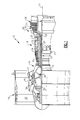
- FIG. 1 schematically illustrates a gas turbine engine 10.
- the example gas turbine engine 10 is a two spool turbofan engine that generally incorporates a fan section 14, a compressor section 16, a combustor section 18 and a turbine section 20.
- Alternative engines might include fewer or additional sections such as an augmenter section (not shown), among other systems or features.
- the fan section 14 drives air along a bypass flow path
- the compressor section 16 drives air along a core flow path for compression and communication into the combustor section 18.
- the hot combustion gases generated in the combustor section 18 are expanded through the turbine section 20.
- This view is highly schematic and is included to provide a basic understanding of the gas turbine engine 10 and not to limit the disclosure. This disclosure extends to all types of gas turbine engines and to all types of applications, including but not limited to, three spool turbofan configurations.
- the example gas turbine engine 10 of Figure 1 generally includes at least a low speed spool 22 and a high speed spool 24 mounted for rotation about an engine centerline axis 12 relative to an engine static structure 27 via several bearing systems 29.
- the low speed spool 22 generally includes an inner shaft 31 that interconnects a fan 33, a low pressure compressor 17, and a low pressure turbine 21.
- the inner shaft 31 can connect to the fan 33 through a geared architecture 35 to drive the fan 33 at a lower speed than the low speed spool 22.
- the geared architecture 35 is schematically depicted between the fan 33 and the low pressure compressor 17, the geared architecture 35 could be disposed at other locations of the gas turbine engine 10.
- the high speed spool 24 includes an outer shaft 37 that interconnects a high pressure compressor 19 and a high pressure turbine 23.
- a combustor 15 is arranged between the high pressure compressor 19 and the high pressure turbine 23.
- the inner shaft 31 and the outer shaft 37 are concentric and rotate about the engine centerline axis 12.
- a core airflow is compressed by the low pressure compressor 17 and the high pressure compressor 19, is mixed with fuel and burned within the combustor 15, and is then expanded over the high pressure turbine 23 and the low pressure turbine 21.
- the turbines 21, 23 rotationally drive the low speed spool 22 and the high speed spool 24 in response to the expansion.
- the compressor section 16 and the turbine section 20 can each include alternating rows of rotor assemblies 39 and vane assemblies 41.
- the rotor assemblies 39 carry a plurality of rotating blades, while each vane assembly 41 includes a plurality of stator vanes.
- the blades of the rotor assemblies 39 create or extract energy (in the form of pressure) from core airflow that is communicated through the gas turbine engine 10.
- the vanes of the vane assemblies 41 direct airflow to the blades of the rotor assemblies 39 to either add or extract energy.
- the gas turbine engine 10 includes a plurality of parts that can be manufactured in a casting process, such as an investment casting process or other suitable casting process.
- a casting process such as an investment casting process or other suitable casting process.
- the blades and vanes carried in the compressor section 16 and the turbine section 20 of the gas turbine engine 10 can be manufactured in a casting process.
- the blades and the vanes, especially those in the turbine section 20 may be subjected to repetitive thermal cycling under widely ranging temperatures and pressures. Therefore, these parts may require internal cooling passages for cooling the part during engine operation.
- An example core for casting internal cooling circuits into a part is discussed below.
- Figure 2 illustrates a part 40 that can be cast in a casting process such as an investment casting process.
- the part 40 is an airfoil that can be incorporated into the compressor section 16 or the turbine section 20.
- BOAS blade outer air seals
- the exemplary part 40 includes an airfoil 42 that extends between a tip portion 44 and a root portion 46.
- the root portion 46 can include a fir-tree configuration 49 for attachment to a rotor assembly (not shown) for circumferential rotation about the engine centerline axis 12. Of course, other attachment configurations are also contemplated.
- the airfoil 42 extends between a leading edge 48 and a trailing edge 50, and includes a suction side 52 and a pressure side 54.
- the root portion 46 can also include a platform 56 that defines an inner gas path of the part 40.
- the part 40 includes an internal cooling circuit 58 (See Figure 3 ) that can be cast into the part 40 by employing a core 60 in a casting process.
- the part 40 is illustrated in Figure 2 prior to removal of the core 60.
- the internal cooling circuit 58 includes a plurality of cooling openings 62 that extend through an exterior surface of the airfoil 42.
- the plurality of cooling openings 62 include filmhole cooling openings that communicate a cooling film onto an outer surface of the airfoil 42 to cool the part 40 during engine operation.
- the core 60 is a ceramic core that is used during the casting process to define the internal cooling circuit 58, including the plurality of cooling openings 62.
- the core 60 can include any suitable ceramic material.
- the core 60 could exclude any refractory metal core (RMC) portions, although RMC portions could also be used.
- the core 60 forms the plurality of cooling openings 62 of the part 40 without the need for drilling such cooling openings 62.
- the core 60 is the inverse (i.e., the 3D "negative") of the internal structure of the part 40.
- the core 60 can be removed in a secondary operation such as a leaching operation.
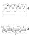
- Figure 3 illustrates a sectional view of the part 40 through section A-A of Figure 2 .
- the part 40 is again illustrated prior to removal of the core 60 from the part 40.
- the core 60 extends between a first wall 64 and a second wall 66 of the part 40.
- the core 60 includes a core body 68 and a plurality of cooling hole forming portions 70 that extend from the core body 68 along a length L of the core body 68.
- the length L of the core body 68 can extend between the tip portion 44 and the root portion 46 of the part 40.
- a thickness T of the core body 68 extends between a first side 69 and a second side 71 of the core body 68.
- the core body 68 includes a varying thickness across the length L of the core body 68.
- the core body 68 defines a first thickness T1 at a first length L1 of the core body 68 and a second thickness T2 at a second length L2 of the core body 68.
- the remaining length of the core body 68 can similarly vary between thicknesses T1 and T2.
- the length L and thickness T of the core body 68 will vary depending on the type of part 40 being cast, and it should be understood that the illustrated lengths and thicknesses are shown for exemplary purposes only and in no way limit this disclosure.
- the first side 69 of the core 60 can include a flat section 73.
- the second side 71 can include an undulating shaped section 72.
- the undulating shaped section 72 includes a plurality of peak portions 74 and a plurality of trough portions 76 that are interposed between adjacent peak portions 74. In this embodiment, one trough portion 76 extends between peak portions 74, and the undulating shaped section 72 faces the pressure side 54 of the part 40.
- the core 60 can also include a plurality of cooling hole forming portions 70 that protrude from the undulating shaped section 72 of the core body 68.
- Each example cooling hole forming portion 70 includes a metering section 80 and a diffusing section 82, although each cooling hole forming portion 70 could include fewer or additional features.
- the metering sections 80 extend between the diffusing sections 82 and the core body 68.
- each metering section 80 is generally rectangular shaped (in cross-section) and each diffusing section 82 is generally triangular shaped (in cross-section), although other cross-sectional shapes are also contemplated, including but not limited to circular, oblong, square, rectangular, conical, pyramidal triangular, etc.
- the metering sections 80 of the cooling hole forming portions 70 can have equivalent diameters.
- the diffusing sections 82 include varying diameters and are of varying sizes.
- the metering sections 80 of the cooling hole forming portions 70 establish the flow rate of cooling airflow through the part 40.
- the diffusing sections 82 slow the cooling airflow down, allowing the cooling airflow to stay attached to the external surface of the part 40 and provide a thin layer of cooling film through the cooling opening 62.
- a first cooling hole forming portion 70A extends a first distance D1 from an external surface of the core body 68, while a second cooling hole forming portion 70B that is spaced from the first cooling hole forming portion 70A extends a second distance D2 from the external surface of the core body 68.
- the first distance D1 and the second distance D2 are different distances.
- the second distance D2 is smaller than the first distance D1.
- This pattern can be repeated along the length L of the core body 68, such as in a staggered arrangement. Other configurations are also contemplated.
- the metering sections 80 and diffusing sections 82 combine to define a cross-sectional area AR of each cooling hole forming portion 70.
- adjacent cooling hole forming portions 70 include varying cross-sectional areas AR1 and AR2.
- the cross-sectional area AR1 of a first cooling hole forming portion 70A is a greater cross-sectional area than a cross-sectional area AR2 of the second cooling hole forming portion 70B.
- This pattern can be repeated along the length L of the core 60.
- a cross-sectional area AR3 of each metering section 80 is the same for each cooling hole forming portion 70, while a cross-sectional area AR4 of each diffusing section 82 varies for each cooling hole forming portion 70.
- the cross-sectional areas established by the metering sections 80 and the diffusing sections 82 can vary.
- Figure 4 illustrates a first cross-sectional slice through section B-B of Figure 3 .
- a cross-sectional area AR1 of each of the cooling hole forming portions 70 is the same through section B-B because this section extends through the metering sections 80 which have equivalent cross-sectional areas (i.e., the cross-sectional area of each metering section 80 is the same cross-sectional area AR1).
- portions of section B-B also extend through the core body 68.
- the stiffness of the core 60 is increased through section B-B by incorporating the undulating shaped section 72, which includes a cross-sectional area AR2 at each peak portion 74.
- the total cross sectional area (i.e., the sum of all cross-sectional areas A1, A2) of the core body 68 and the cooling hole forming portions 70 through section B-B is sufficient to meet the stiffness requirements of the core 60.
- the core stiffness must be great enough to withstand the forces that may occur during a casting process, such as shear stress and bending moments that can occur during wax, ceramic or metallic injection.
- Figure 5 illustrates yet another cross-sectional slice through section C-C of Figure 3 .
- a cross-sectional area AR of each cooling hole forming portion 70 varies through the section C-C.
- the cross-sectional area AR will vary along the length L.
- a first cooling hole forming portion 70A includes a first cross sectional area AR1, while a second cooling hole forming portion 70B includes a second cross-sectional area AR2.
- the first cross sectional area AR1 is a different cross-sectional area than the second cross-sectional area AR2.
- the first cross-sectional area AR1 is greater than the second cross-sectional area AR2.
- This pattern can be repeated along the length L of the core body 68, such as in a staggered arrangement. Other configurations are also contemplated.
- a total cross-sectional area of all of the plurality of cooling hole forming portions 70 (i.e., the sum of all cross-sectional areas AR1 and AR2) provides adequate core stiffness for withstanding forces that may occur during a casting process, such as shear stress and bending moments that can occur during wax, ceramic or metallic injection. Therefore, the cooling hole forming portions 70 (and relatedly the cooling openings 62 of the part 40) can be cast. Additional finishing operations, such as drilling the cooling openings, are not required. Also, in the illustrated embodiments, the core 60 excludes any refractory metal core (RMC) portions. That is, RMC portions are not necessary to provide the cooling openings 62, although it should be understood that RMC portions could be incorporated into the core 60.
- RMC refractory metal core
- the core 60 illustrated in Figures 2-5 can be cast in a casting process, such as a fugitive casting process.
- a casting process such as a fugitive casting process.
- One example casting process is illustrated in U.S. Patent Publication 2011/0094698 , which is incorporated herein by reference.
- this disclosure is not limited to such a casting process, and it should be understood that other casting operations could be used to cast the core 60.
- the core 60 can be utilized within a known casting operation.
- the core 60 can be employed in an investment casting operation to cast a part, such as the part 40 illustrated herein.
- a part 40 can be formed having an internal cooling circuit 58 that includes a cavity having an undulating shape and a plurality of cooling openings 62 that can extend various distances from the cavity (See Figure 3 , core 60 would be removed leaving voids that represent the cavity and the cooling openings 62).
- the cooling openings 62 could be formed having different cross-sectional areas.
Landscapes
- Engineering & Computer Science (AREA)
- Mechanical Engineering (AREA)
- General Engineering & Computer Science (AREA)
- Molds, Cores, And Manufacturing Methods Thereof (AREA)
Abstract
Description
- This disclosure relates to a core employable in a casting process to manufacture a part.
- Gas turbine engines are widely used in aircraft propulsion, electric power generation, ship propulsion and pumps. Many gas turbine engine parts are manufactured in a casting process. One example casting process is known as investment casting. Investment casting can be used to manufacture metallic parts having relatively complex geometries, such as gas turbine engine parts requiring internal cooling circuits. Blades and vanes are examples of such parts.
- The investment casting process utilizes a mold having one or more mold cavities that include a shape generally corresponding to a part to be cast. A wax pattern of the part can be formed by injecting wax material around a ceramic core. A shell is formed around the core in a shelling process. The shell is fired to harden the shell and form the mold, which includes the shell having one or more parts defining compartments that include the core. Molten material is communicated into the mold to cast the part. The shell and core are removed once the molten material cools and solidifies, thereby providing a cast part having an internal cooling circuitry.
- The cast part may require cooling holes that are drilled into the body of the part. Such cooling holes may be desired to extend part life because of the relatively extreme operating conditions the part can be subjected to during engine operation.
- A core for a casting process includes a core body and a first cooling hole forming portion that extends from the core body. The core body includes a varying thickness across a length of the core body.
- In an embodiment of the foregoing core, the core body can include a ceramic core body.
- In a further embodiment of either of the foregoing embodiments, the first cooling hole forming portion can include at least a metering section and a diffusing section, and the metering section can be disposed between the core body and the metering section.
- In a further embodiment of any of the foregoing embodiments, a second cooling hole forming portion can extend from the core body. The first cooling hole forming portion can include a first cross-sectional area and the second cooling hole forming portion can include a second cross sectional area that is different from the first cross-sectional area.
- In a further embodiment of any of the foregoing embodiments, a second cooling hole forming portion can extend from the core body. The first cooling hole forming portion can extend a first distance from the core body and the second cooling hole forming portion can extend a second distance from the core body. The first distance can be different from the second distance.
- In a further embodiment of any of the foregoing embodiments, the core body can include an undulating shaped section.
- In a further embodiment of any of the foregoing embodiments, the undulating shaped section can include a plurality of peak portions and a plurality of trough portions.
- In another exemplary embodiment, a casting process includes casting cooling holes into a gas turbine engine part using a core having a core body and a plurality of cooling hole forming portions that extend from the core body. At least a portion of the plurality of cooling hole forming portions can include different cross-sectional areas.
- In a further embodiment of the foregoing casting process embodiment, the core can be cast in a fugitive casting process.
- In a further embodiment of either of the foregoing casting process embodiments, the core body can be provided with an undulating shaped section.
- In a further embodiment of any of the foregoing casting process embodiments, a distance that at least a portion of the plurality of cooling hole forming portions extend from the core body can be varied.
- In a further embodiment of any of the foregoing casting process embodiments, a thickness of the core body along a length of the core body can be varied.
- In yet another exemplary embodiment, a part for a gas turbine engine includes an internal cooling circuit having a cavity, a first cooling opening, and a second cooling opening spaced from the first cooling opening along a length of the cavity. The first cooling opening extends a first distance from the cavity and the second cooling opening extends a second distance from the cavity that is different from the first distance.
- In a further embodiment of the foregoing part, the part can be an airfoil.
- In a further embodiment of either of the foregoing part embodiments, the cavity can include an undulating shape that extends along the length.
- In a further embodiment of any of the foregoing part embodiments, the first cooling opening can include a first cross-sectional area and the second cooling opening can include a second cross-sectional area that can be different from the first cross-sectional area.
- In a further embodiment of any of the foregoing part embodiments, each of the first cooling openings and the second cooling opening can extend through an exterior surface of the part.
- The various features and advantages of this disclosure will become apparent to those skilled in the art from the following detailed description. The drawings that accompany the detailed description can be briefly described as follows.
-
-
Figure 1 schematically illustrates a gas turbine engine. -
Figure 2 illustrates a gas turbine engine part. -
Figure 3 illustrates a sectional view of the part ofFigure 2 including a core that can be used to cast the part. -
Figure 4 illustrates a first view of the core ofFigure 3 . -
Figure 5 illustrates a second view of the core ofFigure 3 . -
Figure 1 schematically illustrates agas turbine engine 10. The examplegas turbine engine 10 is a two spool turbofan engine that generally incorporates afan section 14, acompressor section 16, acombustor section 18 and aturbine section 20. Alternative engines might include fewer or additional sections such as an augmenter section (not shown), among other systems or features. Generally, thefan section 14 drives air along a bypass flow path, while thecompressor section 16 drives air along a core flow path for compression and communication into thecombustor section 18. The hot combustion gases generated in thecombustor section 18 are expanded through theturbine section 20. - This view is highly schematic and is included to provide a basic understanding of the
gas turbine engine 10 and not to limit the disclosure. This disclosure extends to all types of gas turbine engines and to all types of applications, including but not limited to, three spool turbofan configurations. - The example
gas turbine engine 10 ofFigure 1 generally includes at least alow speed spool 22 and ahigh speed spool 24 mounted for rotation about anengine centerline axis 12 relative to an enginestatic structure 27 viaseveral bearing systems 29. Thelow speed spool 22 generally includes aninner shaft 31 that interconnects afan 33, alow pressure compressor 17, and alow pressure turbine 21. Theinner shaft 31 can connect to thefan 33 through a gearedarchitecture 35 to drive thefan 33 at a lower speed than thelow speed spool 22. Although the gearedarchitecture 35 is schematically depicted between thefan 33 and thelow pressure compressor 17, the gearedarchitecture 35 could be disposed at other locations of thegas turbine engine 10. Thehigh speed spool 24 includes anouter shaft 37 that interconnects ahigh pressure compressor 19 and ahigh pressure turbine 23. - A
combustor 15 is arranged between thehigh pressure compressor 19 and thehigh pressure turbine 23. Theinner shaft 31 and theouter shaft 37 are concentric and rotate about theengine centerline axis 12. A core airflow is compressed by thelow pressure compressor 17 and thehigh pressure compressor 19, is mixed with fuel and burned within thecombustor 15, and is then expanded over thehigh pressure turbine 23 and thelow pressure turbine 21. Theturbines low speed spool 22 and thehigh speed spool 24 in response to the expansion. - The
compressor section 16 and theturbine section 20 can each include alternating rows ofrotor assemblies 39 andvane assemblies 41. Therotor assemblies 39 carry a plurality of rotating blades, while eachvane assembly 41 includes a plurality of stator vanes. The blades of therotor assemblies 39 create or extract energy (in the form of pressure) from core airflow that is communicated through thegas turbine engine 10. The vanes of thevane assemblies 41 direct airflow to the blades of therotor assemblies 39 to either add or extract energy. - The
gas turbine engine 10 includes a plurality of parts that can be manufactured in a casting process, such as an investment casting process or other suitable casting process. For example, the blades and vanes carried in thecompressor section 16 and theturbine section 20 of thegas turbine engine 10 can be manufactured in a casting process. The blades and the vanes, especially those in theturbine section 20, may be subjected to repetitive thermal cycling under widely ranging temperatures and pressures. Therefore, these parts may require internal cooling passages for cooling the part during engine operation. An example core for casting internal cooling circuits into a part is discussed below. -
Figure 2 illustrates apart 40 that can be cast in a casting process such as an investment casting process. In this example, thepart 40 is an airfoil that can be incorporated into thecompressor section 16 or theturbine section 20. However, the various features of this disclosure are applicable to any cast part of the gas turbine engine, or any other part, including but not limited to, blade outer air seals (BOAS). - The
exemplary part 40 includes anairfoil 42 that extends between atip portion 44 and aroot portion 46. Theroot portion 46 can include a fir-tree configuration 49 for attachment to a rotor assembly (not shown) for circumferential rotation about theengine centerline axis 12. Of course, other attachment configurations are also contemplated. Theairfoil 42 extends between aleading edge 48 and a trailingedge 50, and includes asuction side 52 and apressure side 54. Theroot portion 46 can also include aplatform 56 that defines an inner gas path of thepart 40. - The
part 40 includes an internal cooling circuit 58 (SeeFigure 3 ) that can be cast into thepart 40 by employing a core 60 in a casting process. Thepart 40 is illustrated inFigure 2 prior to removal of thecore 60. Theinternal cooling circuit 58 includes a plurality of coolingopenings 62 that extend through an exterior surface of theairfoil 42. In this example, the plurality of coolingopenings 62 include filmhole cooling openings that communicate a cooling film onto an outer surface of theairfoil 42 to cool thepart 40 during engine operation. - In the example embodiment, the
core 60 is a ceramic core that is used during the casting process to define theinternal cooling circuit 58, including the plurality of coolingopenings 62. The core 60 can include any suitable ceramic material. The core 60 could exclude any refractory metal core (RMC) portions, although RMC portions could also be used. The core 60 forms the plurality of coolingopenings 62 of thepart 40 without the need for drillingsuch cooling openings 62. In other words, thecore 60 is the inverse (i.e., the 3D "negative") of the internal structure of thepart 40. After thepart 40 is cast, the core 60 can be removed in a secondary operation such as a leaching operation. -
Figure 3 illustrates a sectional view of thepart 40 through section A-A ofFigure 2 . InFigure 3 , thepart 40 is again illustrated prior to removal of the core 60 from thepart 40. Thecore 60 extends between afirst wall 64 and asecond wall 66 of thepart 40. Thecore 60 includes acore body 68 and a plurality of coolinghole forming portions 70 that extend from thecore body 68 along a length L of thecore body 68. The length L of thecore body 68 can extend between thetip portion 44 and theroot portion 46 of thepart 40. A thickness T of thecore body 68 extends between afirst side 69 and a second side 71 of thecore body 68. - The
core body 68 includes a varying thickness across the length L of thecore body 68. For example, thecore body 68 defines a first thickness T1 at a first length L1 of thecore body 68 and a second thickness T2 at a second length L2 of thecore body 68. The remaining length of thecore body 68 can similarly vary between thicknesses T1 and T2. Of course, other configurations are also contemplated as within the scope of this disclosure. The length L and thickness T of thecore body 68 will vary depending on the type ofpart 40 being cast, and it should be understood that the illustrated lengths and thicknesses are shown for exemplary purposes only and in no way limit this disclosure. - The
first side 69 of the core 60 can include a flat section 73. The second side 71 can include an undulating shapedsection 72. The undulating shapedsection 72 includes a plurality ofpeak portions 74 and a plurality oftrough portions 76 that are interposed betweenadjacent peak portions 74. In this embodiment, onetrough portion 76 extends betweenpeak portions 74, and the undulating shapedsection 72 faces thepressure side 54 of thepart 40. - The core 60 can also include a plurality of cooling
hole forming portions 70 that protrude from the undulating shapedsection 72 of thecore body 68. Each example coolinghole forming portion 70 includes ametering section 80 and a diffusingsection 82, although each coolinghole forming portion 70 could include fewer or additional features. Themetering sections 80 extend between the diffusingsections 82 and thecore body 68. Once thecore 60 is removed from thepart 40, the voids left by removal of the coolinghole forming portions 70 within the internal portion of thepart 40 establish the plurality of coolingopenings 62 of theinternal cooling circuit 58, while removal of thecore body 68 leaves a void that corresponds to a cavity of theinternal cooling circuit 58. - In the illustrated embodiment, each
metering section 80 is generally rectangular shaped (in cross-section) and each diffusingsection 82 is generally triangular shaped (in cross-section), although other cross-sectional shapes are also contemplated, including but not limited to circular, oblong, square, rectangular, conical, pyramidal triangular, etc. Themetering sections 80 of the coolinghole forming portions 70 can have equivalent diameters. However, the diffusingsections 82 include varying diameters and are of varying sizes. - The
metering sections 80 of the coolinghole forming portions 70 establish the flow rate of cooling airflow through thepart 40. The diffusingsections 82 slow the cooling airflow down, allowing the cooling airflow to stay attached to the external surface of thepart 40 and provide a thin layer of cooling film through thecooling opening 62. - A first cooling
hole forming portion 70A extends a first distance D1 from an external surface of thecore body 68, while a second coolinghole forming portion 70B that is spaced from the first coolinghole forming portion 70A extends a second distance D2 from the external surface of thecore body 68. The first distance D1 and the second distance D2 are different distances. In this example, the second distance D2 is smaller than the first distance D1. This pattern can be repeated along the length L of thecore body 68, such as in a staggered arrangement. Other configurations are also contemplated. - The
metering sections 80 and diffusingsections 82 combine to define a cross-sectional area AR of each coolinghole forming portion 70. In this embodiment, adjacent coolinghole forming portions 70 include varying cross-sectional areas AR1 and AR2. For example, the cross-sectional area AR1 of a first coolinghole forming portion 70A is a greater cross-sectional area than a cross-sectional area AR2 of the second coolinghole forming portion 70B. This pattern can be repeated along the length L of thecore 60. In one example, a cross-sectional area AR3 of eachmetering section 80 is the same for each coolinghole forming portion 70, while a cross-sectional area AR4 of each diffusingsection 82 varies for each coolinghole forming portion 70. However, the cross-sectional areas established by themetering sections 80 and the diffusingsections 82 can vary. -
Figure 4 illustrates a first cross-sectional slice through section B-B ofFigure 3 . As can be appreciated, a cross-sectional area AR1 of each of the coolinghole forming portions 70 is the same through section B-B because this section extends through themetering sections 80 which have equivalent cross-sectional areas (i.e., the cross-sectional area of eachmetering section 80 is the same cross-sectional area AR1). However, portions of section B-B also extend through thecore body 68. The stiffness of thecore 60 is increased through section B-B by incorporating the undulating shapedsection 72, which includes a cross-sectional area AR2 at eachpeak portion 74. In other words, the total cross sectional area (i.e., the sum of all cross-sectional areas A1, A2) of thecore body 68 and the coolinghole forming portions 70 through section B-B is sufficient to meet the stiffness requirements of thecore 60. The core stiffness must be great enough to withstand the forces that may occur during a casting process, such as shear stress and bending moments that can occur during wax, ceramic or metallic injection. -
Figure 5 illustrates yet another cross-sectional slice through section C-C ofFigure 3 . A cross-sectional area AR of each coolinghole forming portion 70 varies through the section C-C. In other words, for any longitudinal slice that extends through only the cooling hole forming portions 70 (and not through any portion of the core body 68), the cross-sectional area AR will vary along the length L. - A first cooling
hole forming portion 70A includes a first cross sectional area AR1, while a second coolinghole forming portion 70B includes a second cross-sectional area AR2. The first cross sectional area AR1 is a different cross-sectional area than the second cross-sectional area AR2. In this example, the first cross-sectional area AR1 is greater than the second cross-sectional area AR2. This pattern can be repeated along the length L of thecore body 68, such as in a staggered arrangement. Other configurations are also contemplated. - A total cross-sectional area of all of the plurality of cooling hole forming portions 70 (i.e., the sum of all cross-sectional areas AR1 and AR2) provides adequate core stiffness for withstanding forces that may occur during a casting process, such as shear stress and bending moments that can occur during wax, ceramic or metallic injection. Therefore, the cooling hole forming portions 70 (and relatedly the cooling
openings 62 of the part 40) can be cast. Additional finishing operations, such as drilling the cooling openings, are not required. Also, in the illustrated embodiments, thecore 60 excludes any refractory metal core (RMC) portions. That is, RMC portions are not necessary to provide the coolingopenings 62, although it should be understood that RMC portions could be incorporated into thecore 60. - The core 60 illustrated in
Figures 2-5 can be cast in a casting process, such as a fugitive casting process. One example casting process is illustrated inU.S. Patent Publication 2011/0094698 , which is incorporated herein by reference. However, this disclosure is not limited to such a casting process, and it should be understood that other casting operations could be used to cast thecore 60. - After the
core 60 is cast, the core 60 can be utilized within a known casting operation. For example, the core 60 can be employed in an investment casting operation to cast a part, such as thepart 40 illustrated herein. By using acore 60 having the core body 68 (with a varying thickness across its length) and the cooling hole forming portions 70 (that extend at varying distances from the core body 68), apart 40 can be formed having aninternal cooling circuit 58 that includes a cavity having an undulating shape and a plurality of coolingopenings 62 that can extend various distances from the cavity (SeeFigure 3 ,core 60 would be removed leaving voids that represent the cavity and the cooling openings 62). The coolingopenings 62 could be formed having different cross-sectional areas. - Although the different examples have the specific examples shown in the illustrations, embodiments of this disclosure are not limited to those particular combinations. It is possible to use some of the components or features from one of the examples or features in combination with features or components from another one of the examples.
- Furthermore, the forgoing description shall be interpreted as illustrative and not in any limiting in sense. A worker of ordinary skill in the art would understand that certain modifications could come within the scope of this disclosure. For these reasons, the following claims should be studied to determine the true scope and content of this disclosure.
Claims (15)
- A core (60) for a casting process, comprising:a core body (68); anda first cooling hole forming portion (70) that extends from said core body (68), wherein said core body (68) includes a varying thickness across a length of said core body (68).
- The core as recited in claim 1, wherein said core body (68) includes a ceramic core body.
- The core as recited in claim 1 or 2, wherein said first cooling hole forming portion (70) includes at least a metering section (80) and a diffusing section (82), and said metering section (80) is disposed between said core body (68) and said diffusing section (82).
- The core as recited in any preceding claim, comprising a second cooling hole forming portion (70) that extends from said core body (68), wherein said first cooling hole forming portion (70) includes a first cross-sectional area (AR1) and said second cooling hole forming portion (70) includes a second cross sectional area (AR2) that is different from said first cross-sectional area (AR1).
- The core as recited in any preceding claim, comprising a second cooling hole forming portion (70) that extends from said core body (68), wherein said first cooling hole forming portion (70) extends a first distance (D1) from said core body (68) and said second cooling hole forming portion (70) extends a second distance (D2) from said core body (68), wherein said first distance (D1) is different from said second distance (D2).
- The core as recited in any preceding claim, wherein said core body (68) includes an undulating shaped section.
- The core as recited in claim 6, wherein said undulating shaped section includes a plurality of peak portions (74) and a plurality of trough portions (76).
- A casting process, comprising the steps of:casting cooling holes (62) into a gas turbine engine part using a core (60) having a core body (68) and a plurality of cooling hole forming portions (70) that extend from the core body (68), wherein at least a portion of the plurality of cooling hole forming portions (70) have different cross-sectional areas.
- The method as recited in claim 8, comprising the step of casting the core in a fugitive casting process.
- The method as recited in claim 8 or 9, comprising the step of providing the core body (68) with an undulating shaped section.
- The method as recited in claim 8, 9 or 10, comprising the step of varying a distance (D) that at least a portion of the plurality of cooling hole forming portions (70) extend from the core body (68).
- The method as recited in any of claims 8 to 11, comprising the step of varying a thickness (T) of the core body (68) along a length of the core body (68).
- A part (40) for a gas turbine engine, for example an airfoil, comprising:an internal cooling circuit (58) having a cavity, a first cooling opening (62), and a second cooling opening (62) spaced from said first cooling opening (62) along a length of said cavity, each of said first cooling opening (62) and said second cooling opening (62) optionally extending through an exterior surface of said part (40); and
wherein said first cooling opening (62) extends a first distance (D1) from said cavity and said second cooling opening (62) extends a second distance (D2) from said cavity that is different from said first distance (D1). - The part as recited in claim 13, wherein said cavity includes an undulating shape that extends along said length.
- The part as recited in claim 13 or 14, wherein said first cooling opening (62) includes a first cross-sectional area and said second cooling opening (62) includes a second cross-sectional area that is different from said first cross-sectional area.
Applications Claiming Priority (1)
| Application Number | Priority Date | Filing Date | Title |
|---|---|---|---|
| US13/347,944 US9138804B2 (en) | 2012-01-11 | 2012-01-11 | Core for a casting process |
Publications (3)
| Publication Number | Publication Date |
|---|---|
| EP2614902A2 true EP2614902A2 (en) | 2013-07-17 |
| EP2614902A3 EP2614902A3 (en) | 2017-03-15 |
| EP2614902B1 EP2614902B1 (en) | 2020-11-04 |
Family
ID=47603243
Family Applications (1)
| Application Number | Title | Priority Date | Filing Date |
|---|---|---|---|
| EP13150680.0A Active EP2614902B1 (en) | 2012-01-11 | 2013-01-09 | Core for a casting process |
Country Status (2)
| Country | Link |
|---|---|
| US (1) | US9138804B2 (en) |
| EP (1) | EP2614902B1 (en) |
Cited By (12)
| Publication number | Priority date | Publication date | Assignee | Title |
|---|---|---|---|---|
| US9579714B1 (en) | 2015-12-17 | 2017-02-28 | General Electric Company | Method and assembly for forming components having internal passages using a lattice structure |
| US9968991B2 (en) | 2015-12-17 | 2018-05-15 | General Electric Company | Method and assembly for forming components having internal passages using a lattice structure |
| US9987677B2 (en) | 2015-12-17 | 2018-06-05 | General Electric Company | Method and assembly for forming components having internal passages using a jacketed core |
| US10046389B2 (en) | 2015-12-17 | 2018-08-14 | General Electric Company | Method and assembly for forming components having internal passages using a jacketed core |
| US10099276B2 (en) | 2015-12-17 | 2018-10-16 | General Electric Company | Method and assembly for forming components having an internal passage defined therein |
| US10099284B2 (en) | 2015-12-17 | 2018-10-16 | General Electric Company | Method and assembly for forming components having a catalyzed internal passage defined therein |
| US10099283B2 (en) | 2015-12-17 | 2018-10-16 | General Electric Company | Method and assembly for forming components having an internal passage defined therein |
| US10118217B2 (en) | 2015-12-17 | 2018-11-06 | General Electric Company | Method and assembly for forming components having internal passages using a jacketed core |
| US10137499B2 (en) | 2015-12-17 | 2018-11-27 | General Electric Company | Method and assembly for forming components having an internal passage defined therein |
| US10150158B2 (en) | 2015-12-17 | 2018-12-11 | General Electric Company | Method and assembly for forming components having internal passages using a jacketed core |
| US10286450B2 (en) | 2016-04-27 | 2019-05-14 | General Electric Company | Method and assembly for forming components using a jacketed core |
| US10335853B2 (en) | 2016-04-27 | 2019-07-02 | General Electric Company | Method and assembly for forming components using a jacketed core |
Families Citing this family (1)
| Publication number | Priority date | Publication date | Assignee | Title |
|---|---|---|---|---|
| US10913106B2 (en) | 2018-09-14 | 2021-02-09 | Raytheon Technologies Corporation | Cast-in film cooling hole structures |
Citations (1)
| Publication number | Priority date | Publication date | Assignee | Title |
|---|---|---|---|---|
| US20110094698A1 (en) | 2009-10-28 | 2011-04-28 | Howmet Corporation | Fugitive core tooling and method |
Family Cites Families (13)
| Publication number | Priority date | Publication date | Assignee | Title |
|---|---|---|---|---|
| JPH07279612A (en) * | 1994-04-14 | 1995-10-27 | Mitsubishi Heavy Ind Ltd | Heavy oil burning gas turbine cooling blade |
| US5599166A (en) * | 1994-11-01 | 1997-02-04 | United Technologies Corporation | Core for fabrication of gas turbine engine airfoils |
| US6062817A (en) * | 1998-11-06 | 2000-05-16 | General Electric Company | Apparatus and methods for cooling slot step elimination |
| US7144220B2 (en) | 2004-07-30 | 2006-12-05 | United Technologies Corporation | Investment casting |
| US7278826B2 (en) | 2004-08-18 | 2007-10-09 | Pratt & Whitney Canada Corp. | Airfoil cooling passage trailing edge flow restriction |
| US7186085B2 (en) * | 2004-11-18 | 2007-03-06 | General Electric Company | Multiform film cooling holes |
| US7185695B1 (en) | 2005-09-01 | 2007-03-06 | United Technologies Corporation | Investment casting pattern manufacture |
| FR2896710B1 (en) | 2006-01-27 | 2009-10-30 | Snecma Sa | PROCESS FOR MANUFACTURING TURBOMACHINE COMPONENT WITH COOLING AIR EXHAUST ORIFICES |
| US7610946B2 (en) * | 2007-01-05 | 2009-11-03 | Honeywell International Inc. | Cooled turbine blade cast tip recess |
| US7866370B2 (en) | 2007-01-30 | 2011-01-11 | United Technologies Corporation | Blades, casting cores, and methods |
| US7980819B2 (en) | 2007-03-14 | 2011-07-19 | United Technologies Corporation | Cast features for a turbine engine airfoil |
| US8210814B2 (en) | 2008-06-18 | 2012-07-03 | General Electric Company | Crossflow turbine airfoil |
| US8096771B2 (en) * | 2008-09-25 | 2012-01-17 | Siemens Energy, Inc. | Trailing edge cooling slot configuration for a turbine airfoil |
-
2012
- 2012-01-11 US US13/347,944 patent/US9138804B2/en not_active Expired - Fee Related
-
2013
- 2013-01-09 EP EP13150680.0A patent/EP2614902B1/en active Active
Patent Citations (1)
| Publication number | Priority date | Publication date | Assignee | Title |
|---|---|---|---|---|
| US20110094698A1 (en) | 2009-10-28 | 2011-04-28 | Howmet Corporation | Fugitive core tooling and method |
Cited By (14)
| Publication number | Priority date | Publication date | Assignee | Title |
|---|---|---|---|---|
| US9579714B1 (en) | 2015-12-17 | 2017-02-28 | General Electric Company | Method and assembly for forming components having internal passages using a lattice structure |
| US9968991B2 (en) | 2015-12-17 | 2018-05-15 | General Electric Company | Method and assembly for forming components having internal passages using a lattice structure |
| US9975176B2 (en) | 2015-12-17 | 2018-05-22 | General Electric Company | Method and assembly for forming components having internal passages using a lattice structure |
| US9987677B2 (en) | 2015-12-17 | 2018-06-05 | General Electric Company | Method and assembly for forming components having internal passages using a jacketed core |
| US10046389B2 (en) | 2015-12-17 | 2018-08-14 | General Electric Company | Method and assembly for forming components having internal passages using a jacketed core |
| US10099276B2 (en) | 2015-12-17 | 2018-10-16 | General Electric Company | Method and assembly for forming components having an internal passage defined therein |
| US10099284B2 (en) | 2015-12-17 | 2018-10-16 | General Electric Company | Method and assembly for forming components having a catalyzed internal passage defined therein |
| US10099283B2 (en) | 2015-12-17 | 2018-10-16 | General Electric Company | Method and assembly for forming components having an internal passage defined therein |
| US10118217B2 (en) | 2015-12-17 | 2018-11-06 | General Electric Company | Method and assembly for forming components having internal passages using a jacketed core |
| US10137499B2 (en) | 2015-12-17 | 2018-11-27 | General Electric Company | Method and assembly for forming components having an internal passage defined therein |
| US10150158B2 (en) | 2015-12-17 | 2018-12-11 | General Electric Company | Method and assembly for forming components having internal passages using a jacketed core |
| US10286450B2 (en) | 2016-04-27 | 2019-05-14 | General Electric Company | Method and assembly for forming components using a jacketed core |
| US10335853B2 (en) | 2016-04-27 | 2019-07-02 | General Electric Company | Method and assembly for forming components using a jacketed core |
| US10981221B2 (en) | 2016-04-27 | 2021-04-20 | General Electric Company | Method and assembly for forming components using a jacketed core |
Also Published As
| Publication number | Publication date |
|---|---|
| EP2614902A3 (en) | 2017-03-15 |
| US9138804B2 (en) | 2015-09-22 |
| US20130177448A1 (en) | 2013-07-11 |
| EP2614902B1 (en) | 2020-11-04 |
Similar Documents
| Publication | Publication Date | Title |
|---|---|---|
| EP2614902B1 (en) | Core for a casting process | |
| US9988913B2 (en) | Using inserts to balance heat transfer and stress in high temperature alloys | |
| EP3068975B1 (en) | Gas turbine engine component and corresponding methods of manufacturing | |
| EP2900961B1 (en) | Gas turbine engine airfoil cooling circuit | |
| EP2867472B1 (en) | Turbine vane | |
| US10975705B2 (en) | Gas turbine engine airfoil with wishbone baffle cooling scheme | |
| EP3460189A1 (en) | Gas turbine engine component having vascular engineered lattice structure | |
| US20190085705A1 (en) | Component for a turbine engine with a film-hole | |
| EP3399145B1 (en) | Airfoil comprising a leading edge hybrid skin core cavity | |
| US10300526B2 (en) | Core assembly including studded spacer | |
| EP2956257B1 (en) | Gas turbine engine component cooling passage and space eating core | |
| EP3051066B1 (en) | Casting core with staggered extensions | |
| US11982231B2 (en) | Hourglass airfoil cooling configuration | |
| US20200023428A1 (en) | Rib bumper system | |
| EP3670841B1 (en) | Airfoil with hybrid skincore passage resupply | |
| EP3564485B1 (en) | Airfoils, cores, and methods of manufacture for forming airfoils having fluidly connected platform cooling circuits | |
| US10626735B2 (en) | Double wall turbine gas turbine engine blade cooling configuration |
Legal Events
| Date | Code | Title | Description |
|---|---|---|---|
| PUAI | Public reference made under article 153(3) epc to a published international application that has entered the european phase |
Free format text: ORIGINAL CODE: 0009012 |
|
| AK | Designated contracting states |
Kind code of ref document: A2 Designated state(s): AL AT BE BG CH CY CZ DE DK EE ES FI FR GB GR HR HU IE IS IT LI LT LU LV MC MK MT NL NO PL PT RO RS SE SI SK SM TR |
|
| AX | Request for extension of the european patent |
Extension state: BA ME |
|
| RAP1 | Party data changed (applicant data changed or rights of an application transferred) |
Owner name: UNITED TECHNOLOGIES CORPORATION |
|
| PUAL | Search report despatched |
Free format text: ORIGINAL CODE: 0009013 |
|
| AK | Designated contracting states |
Kind code of ref document: A3 Designated state(s): AL AT BE BG CH CY CZ DE DK EE ES FI FR GB GR HR HU IE IS IT LI LT LU LV MC MK MT NL NO PL PT RO RS SE SI SK SM TR |
|
| AX | Request for extension of the european patent |
Extension state: BA ME |
|
| RIC1 | Information provided on ipc code assigned before grant |
Ipc: B22C 7/02 20060101AFI20170206BHEP Ipc: B22C 9/10 20060101ALI20170206BHEP Ipc: B22C 9/04 20060101ALI20170206BHEP Ipc: F01D 5/18 20060101ALI20170206BHEP |
|
| STAA | Information on the status of an ep patent application or granted ep patent |
Free format text: STATUS: REQUEST FOR EXAMINATION WAS MADE |
|
| 17P | Request for examination filed |
Effective date: 20170915 |
|
| RBV | Designated contracting states (corrected) |
Designated state(s): AL AT BE BG CH CY CZ DE DK EE ES FI FR GB GR HR HU IE IS IT LI LT LU LV MC MK MT NL NO PL PT RO RS SE SI SK SM TR |
|
| STAA | Information on the status of an ep patent application or granted ep patent |
Free format text: STATUS: EXAMINATION IS IN PROGRESS |
|
| 17Q | First examination report despatched |
Effective date: 20180103 |
|
| GRAP | Despatch of communication of intention to grant a patent |
Free format text: ORIGINAL CODE: EPIDOSNIGR1 |
|
| STAA | Information on the status of an ep patent application or granted ep patent |
Free format text: STATUS: GRANT OF PATENT IS INTENDED |
|
| INTG | Intention to grant announced |
Effective date: 20200511 |
|
| GRAS | Grant fee paid |
Free format text: ORIGINAL CODE: EPIDOSNIGR3 |
|
| GRAA | (expected) grant |
Free format text: ORIGINAL CODE: 0009210 |
|
| STAA | Information on the status of an ep patent application or granted ep patent |
Free format text: STATUS: THE PATENT HAS BEEN GRANTED |
|
| AK | Designated contracting states |
Kind code of ref document: B1 Designated state(s): AL AT BE BG CH CY CZ DE DK EE ES FI FR GB GR HR HU IE IS IT LI LT LU LV MC MK MT NL NO PL PT RO RS SE SI SK SM TR |
|
| REG | Reference to a national code |
Ref country code: GB Ref legal event code: FG4D |
|
| REG | Reference to a national code |
Ref country code: CH Ref legal event code: EP |
|
| REG | Reference to a national code |
Ref country code: AT Ref legal event code: REF Ref document number: 1330143 Country of ref document: AT Kind code of ref document: T Effective date: 20201115 |
|
| REG | Reference to a national code |
Ref country code: DE Ref legal event code: R096 Ref document number: 602013073734 Country of ref document: DE |
|
| REG | Reference to a national code |
Ref country code: IE Ref legal event code: FG4D |
|
| RAP2 | Party data changed (patent owner data changed or rights of a patent transferred) |
Owner name: RAYTHEON TECHNOLOGIES CORPORATION |
|
| REG | Reference to a national code |
Ref country code: NL Ref legal event code: MP Effective date: 20201104 |
|
| REG | Reference to a national code |
Ref country code: AT Ref legal event code: MK05 Ref document number: 1330143 Country of ref document: AT Kind code of ref document: T Effective date: 20201104 |
|
| PG25 | Lapsed in a contracting state [announced via postgrant information from national office to epo] |
Ref country code: NO Free format text: LAPSE BECAUSE OF FAILURE TO SUBMIT A TRANSLATION OF THE DESCRIPTION OR TO PAY THE FEE WITHIN THE PRESCRIBED TIME-LIMIT Effective date: 20210204 Ref country code: PT Free format text: LAPSE BECAUSE OF FAILURE TO SUBMIT A TRANSLATION OF THE DESCRIPTION OR TO PAY THE FEE WITHIN THE PRESCRIBED TIME-LIMIT Effective date: 20210304 Ref country code: FI Free format text: LAPSE BECAUSE OF FAILURE TO SUBMIT A TRANSLATION OF THE DESCRIPTION OR TO PAY THE FEE WITHIN THE PRESCRIBED TIME-LIMIT Effective date: 20201104 Ref country code: RS Free format text: LAPSE BECAUSE OF FAILURE TO SUBMIT A TRANSLATION OF THE DESCRIPTION OR TO PAY THE FEE WITHIN THE PRESCRIBED TIME-LIMIT Effective date: 20201104 Ref country code: GR Free format text: LAPSE BECAUSE OF FAILURE TO SUBMIT A TRANSLATION OF THE DESCRIPTION OR TO PAY THE FEE WITHIN THE PRESCRIBED TIME-LIMIT Effective date: 20210205 |
|
| PG25 | Lapsed in a contracting state [announced via postgrant information from national office to epo] |
Ref country code: BG Free format text: LAPSE BECAUSE OF FAILURE TO SUBMIT A TRANSLATION OF THE DESCRIPTION OR TO PAY THE FEE WITHIN THE PRESCRIBED TIME-LIMIT Effective date: 20210204 Ref country code: AT Free format text: LAPSE BECAUSE OF FAILURE TO SUBMIT A TRANSLATION OF THE DESCRIPTION OR TO PAY THE FEE WITHIN THE PRESCRIBED TIME-LIMIT Effective date: 20201104 Ref country code: ES Free format text: LAPSE BECAUSE OF FAILURE TO SUBMIT A TRANSLATION OF THE DESCRIPTION OR TO PAY THE FEE WITHIN THE PRESCRIBED TIME-LIMIT Effective date: 20201104 Ref country code: IS Free format text: LAPSE BECAUSE OF FAILURE TO SUBMIT A TRANSLATION OF THE DESCRIPTION OR TO PAY THE FEE WITHIN THE PRESCRIBED TIME-LIMIT Effective date: 20210304 Ref country code: SE Free format text: LAPSE BECAUSE OF FAILURE TO SUBMIT A TRANSLATION OF THE DESCRIPTION OR TO PAY THE FEE WITHIN THE PRESCRIBED TIME-LIMIT Effective date: 20201104 Ref country code: LV Free format text: LAPSE BECAUSE OF FAILURE TO SUBMIT A TRANSLATION OF THE DESCRIPTION OR TO PAY THE FEE WITHIN THE PRESCRIBED TIME-LIMIT Effective date: 20201104 Ref country code: PL Free format text: LAPSE BECAUSE OF FAILURE TO SUBMIT A TRANSLATION OF THE DESCRIPTION OR TO PAY THE FEE WITHIN THE PRESCRIBED TIME-LIMIT Effective date: 20201104 |
|
| REG | Reference to a national code |
Ref country code: LT Ref legal event code: MG9D |
|
| PG25 | Lapsed in a contracting state [announced via postgrant information from national office to epo] |
Ref country code: HR Free format text: LAPSE BECAUSE OF FAILURE TO SUBMIT A TRANSLATION OF THE DESCRIPTION OR TO PAY THE FEE WITHIN THE PRESCRIBED TIME-LIMIT Effective date: 20201104 |
|
| PG25 | Lapsed in a contracting state [announced via postgrant information from national office to epo] |
Ref country code: LT Free format text: LAPSE BECAUSE OF FAILURE TO SUBMIT A TRANSLATION OF THE DESCRIPTION OR TO PAY THE FEE WITHIN THE PRESCRIBED TIME-LIMIT Effective date: 20201104 Ref country code: SK Free format text: LAPSE BECAUSE OF FAILURE TO SUBMIT A TRANSLATION OF THE DESCRIPTION OR TO PAY THE FEE WITHIN THE PRESCRIBED TIME-LIMIT Effective date: 20201104 Ref country code: RO Free format text: LAPSE BECAUSE OF FAILURE TO SUBMIT A TRANSLATION OF THE DESCRIPTION OR TO PAY THE FEE WITHIN THE PRESCRIBED TIME-LIMIT Effective date: 20201104 Ref country code: SM Free format text: LAPSE BECAUSE OF FAILURE TO SUBMIT A TRANSLATION OF THE DESCRIPTION OR TO PAY THE FEE WITHIN THE PRESCRIBED TIME-LIMIT Effective date: 20201104 Ref country code: EE Free format text: LAPSE BECAUSE OF FAILURE TO SUBMIT A TRANSLATION OF THE DESCRIPTION OR TO PAY THE FEE WITHIN THE PRESCRIBED TIME-LIMIT Effective date: 20201104 Ref country code: CZ Free format text: LAPSE BECAUSE OF FAILURE TO SUBMIT A TRANSLATION OF THE DESCRIPTION OR TO PAY THE FEE WITHIN THE PRESCRIBED TIME-LIMIT Effective date: 20201104 |
|
| REG | Reference to a national code |
Ref country code: DE Ref legal event code: R097 Ref document number: 602013073734 Country of ref document: DE |
|
| PG25 | Lapsed in a contracting state [announced via postgrant information from national office to epo] |
Ref country code: DK Free format text: LAPSE BECAUSE OF FAILURE TO SUBMIT A TRANSLATION OF THE DESCRIPTION OR TO PAY THE FEE WITHIN THE PRESCRIBED TIME-LIMIT Effective date: 20201104 Ref country code: MC Free format text: LAPSE BECAUSE OF FAILURE TO SUBMIT A TRANSLATION OF THE DESCRIPTION OR TO PAY THE FEE WITHIN THE PRESCRIBED TIME-LIMIT Effective date: 20201104 |
|
| REG | Reference to a national code |
Ref country code: CH Ref legal event code: PL |
|
| PLBE | No opposition filed within time limit |
Free format text: ORIGINAL CODE: 0009261 |
|
| STAA | Information on the status of an ep patent application or granted ep patent |
Free format text: STATUS: NO OPPOSITION FILED WITHIN TIME LIMIT |
|
| PG25 | Lapsed in a contracting state [announced via postgrant information from national office to epo] |
Ref country code: LU Free format text: LAPSE BECAUSE OF NON-PAYMENT OF DUE FEES Effective date: 20210109 |
|
| REG | Reference to a national code |
Ref country code: BE Ref legal event code: MM Effective date: 20210131 |
|
| 26N | No opposition filed |
Effective date: 20210805 |
|
| PG25 | Lapsed in a contracting state [announced via postgrant information from national office to epo] |
Ref country code: AL Free format text: LAPSE BECAUSE OF FAILURE TO SUBMIT A TRANSLATION OF THE DESCRIPTION OR TO PAY THE FEE WITHIN THE PRESCRIBED TIME-LIMIT Effective date: 20201104 Ref country code: IT Free format text: LAPSE BECAUSE OF FAILURE TO SUBMIT A TRANSLATION OF THE DESCRIPTION OR TO PAY THE FEE WITHIN THE PRESCRIBED TIME-LIMIT Effective date: 20201104 Ref country code: NL Free format text: LAPSE BECAUSE OF FAILURE TO SUBMIT A TRANSLATION OF THE DESCRIPTION OR TO PAY THE FEE WITHIN THE PRESCRIBED TIME-LIMIT Effective date: 20201104 |
|
| PG25 | Lapsed in a contracting state [announced via postgrant information from national office to epo] |
Ref country code: LI Free format text: LAPSE BECAUSE OF NON-PAYMENT OF DUE FEES Effective date: 20210131 Ref country code: SI Free format text: LAPSE BECAUSE OF FAILURE TO SUBMIT A TRANSLATION OF THE DESCRIPTION OR TO PAY THE FEE WITHIN THE PRESCRIBED TIME-LIMIT Effective date: 20201104 Ref country code: CH Free format text: LAPSE BECAUSE OF NON-PAYMENT OF DUE FEES Effective date: 20210131 |
|
| PG25 | Lapsed in a contracting state [announced via postgrant information from national office to epo] |
Ref country code: IE Free format text: LAPSE BECAUSE OF NON-PAYMENT OF DUE FEES Effective date: 20210109 |
|
| PG25 | Lapsed in a contracting state [announced via postgrant information from national office to epo] |
Ref country code: IS Free format text: LAPSE BECAUSE OF FAILURE TO SUBMIT A TRANSLATION OF THE DESCRIPTION OR TO PAY THE FEE WITHIN THE PRESCRIBED TIME-LIMIT Effective date: 20210304 |
|
| PG25 | Lapsed in a contracting state [announced via postgrant information from national office to epo] |
Ref country code: BE Free format text: LAPSE BECAUSE OF NON-PAYMENT OF DUE FEES Effective date: 20210131 |
|
| PG25 | Lapsed in a contracting state [announced via postgrant information from national office to epo] |
Ref country code: HU Free format text: LAPSE BECAUSE OF FAILURE TO SUBMIT A TRANSLATION OF THE DESCRIPTION OR TO PAY THE FEE WITHIN THE PRESCRIBED TIME-LIMIT; INVALID AB INITIO Effective date: 20130109 |
|
| P01 | Opt-out of the competence of the unified patent court (upc) registered |
Effective date: 20230520 |
|
| PG25 | Lapsed in a contracting state [announced via postgrant information from national office to epo] |
Ref country code: CY Free format text: LAPSE BECAUSE OF FAILURE TO SUBMIT A TRANSLATION OF THE DESCRIPTION OR TO PAY THE FEE WITHIN THE PRESCRIBED TIME-LIMIT Effective date: 20201104 |
|
| PGFP | Annual fee paid to national office [announced via postgrant information from national office to epo] |
Ref country code: GB Payment date: 20231219 Year of fee payment: 12 |
|
| PGFP | Annual fee paid to national office [announced via postgrant information from national office to epo] |
Ref country code: FR Payment date: 20231219 Year of fee payment: 12 |
|
| PG25 | Lapsed in a contracting state [announced via postgrant information from national office to epo] |
Ref country code: MK Free format text: LAPSE BECAUSE OF FAILURE TO SUBMIT A TRANSLATION OF THE DESCRIPTION OR TO PAY THE FEE WITHIN THE PRESCRIBED TIME-LIMIT Effective date: 20201104 |
|
| PGFP | Annual fee paid to national office [announced via postgrant information from national office to epo] |
Ref country code: DE Payment date: 20231219 Year of fee payment: 12 |