EP2611397B1 - Expandable devices - Google Patents
Expandable devices Download PDFInfo
- Publication number
- EP2611397B1 EP2611397B1 EP11752450.4A EP11752450A EP2611397B1 EP 2611397 B1 EP2611397 B1 EP 2611397B1 EP 11752450 A EP11752450 A EP 11752450A EP 2611397 B1 EP2611397 B1 EP 2611397B1
- Authority
- EP
- European Patent Office
- Prior art keywords
- inward facing
- stent
- strut
- apex
- lumen support
- Prior art date
- Legal status (The legal status is an assumption and is not a legal conclusion. Google has not performed a legal analysis and makes no representation as to the accuracy of the status listed.)
- Active
Links
- 230000002792 vascular Effects 0.000 description 10
- 238000013461 design Methods 0.000 description 9
- 229910001000 nickel titanium Inorganic materials 0.000 description 6
- HLXZNVUGXRDIFK-UHFFFAOYSA-N nickel titanium Chemical compound [Ti].[Ti].[Ti].[Ti].[Ti].[Ti].[Ti].[Ti].[Ti].[Ti].[Ti].[Ni].[Ni].[Ni].[Ni].[Ni].[Ni].[Ni].[Ni].[Ni].[Ni].[Ni].[Ni].[Ni].[Ni] HLXZNVUGXRDIFK-UHFFFAOYSA-N 0.000 description 6
- 238000000034 method Methods 0.000 description 5
- 230000007704 transition Effects 0.000 description 5
- 239000010935 stainless steel Substances 0.000 description 4
- 229910001220 stainless steel Inorganic materials 0.000 description 4
- 210000005166 vasculature Anatomy 0.000 description 4
- 210000004204 blood vessel Anatomy 0.000 description 3
- 210000004351 coronary vessel Anatomy 0.000 description 3
- 210000001105 femoral artery Anatomy 0.000 description 3
- 230000003902 lesion Effects 0.000 description 3
- 238000004519 manufacturing process Methods 0.000 description 3
- 229910052751 metal Inorganic materials 0.000 description 3
- 239000002184 metal Substances 0.000 description 3
- 229910001092 metal group alloy Inorganic materials 0.000 description 3
- 229910000684 Cobalt-chrome Inorganic materials 0.000 description 2
- WAIPAZQMEIHHTJ-UHFFFAOYSA-N [Cr].[Co] Chemical compound [Cr].[Co] WAIPAZQMEIHHTJ-UHFFFAOYSA-N 0.000 description 2
- 210000003484 anatomy Anatomy 0.000 description 2
- 230000008901 benefit Effects 0.000 description 2
- 210000001715 carotid artery Anatomy 0.000 description 2
- 239000010952 cobalt-chrome Substances 0.000 description 2
- 238000002788 crimping Methods 0.000 description 2
- 239000007943 implant Substances 0.000 description 2
- 230000006872 improvement Effects 0.000 description 2
- 239000000463 material Substances 0.000 description 2
- 230000002093 peripheral effect Effects 0.000 description 2
- 229910000531 Co alloy Inorganic materials 0.000 description 1
- MWCLLHOVUTZFKS-UHFFFAOYSA-N Methyl cyanoacrylate Chemical compound COC(=O)C(=C)C#N MWCLLHOVUTZFKS-UHFFFAOYSA-N 0.000 description 1
- 208000031481 Pathologic Constriction Diseases 0.000 description 1
- 208000018262 Peripheral vascular disease Diseases 0.000 description 1
- 208000012287 Prolapse Diseases 0.000 description 1
- 229910045601 alloy Inorganic materials 0.000 description 1
- 239000000956 alloy Substances 0.000 description 1
- 210000000709 aorta Anatomy 0.000 description 1
- 238000013459 approach Methods 0.000 description 1
- 210000001367 artery Anatomy 0.000 description 1
- 238000005452 bending Methods 0.000 description 1
- 230000000747 cardiac effect Effects 0.000 description 1
- 238000013131 cardiovascular procedure Methods 0.000 description 1
- 230000010261 cell growth Effects 0.000 description 1
- 230000008859 change Effects 0.000 description 1
- 230000006835 compression Effects 0.000 description 1
- 238000007906 compression Methods 0.000 description 1
- 238000007887 coronary angioplasty Methods 0.000 description 1
- 230000007547 defect Effects 0.000 description 1
- 230000001419 dependent effect Effects 0.000 description 1
- 238000011161 development Methods 0.000 description 1
- 238000002224 dissection Methods 0.000 description 1
- 230000002526 effect on cardiovascular system Effects 0.000 description 1
- 239000013013 elastic material Substances 0.000 description 1
- 238000005516 engineering process Methods 0.000 description 1
- 210000003090 iliac artery Anatomy 0.000 description 1
- 210000003111 iliac vein Anatomy 0.000 description 1
- 238000005304 joining Methods 0.000 description 1
- 238000003698 laser cutting Methods 0.000 description 1
- 230000014759 maintenance of location Effects 0.000 description 1
- 230000007246 mechanism Effects 0.000 description 1
- 150000002739 metals Chemical class 0.000 description 1
- 238000012986 modification Methods 0.000 description 1
- 230000004048 modification Effects 0.000 description 1
- 229920000642 polymer Polymers 0.000 description 1
- 230000002028 premature Effects 0.000 description 1
- 230000009467 reduction Effects 0.000 description 1
- 210000002254 renal artery Anatomy 0.000 description 1
- 239000012858 resilient material Substances 0.000 description 1
- 239000012781 shape memory material Substances 0.000 description 1
- 229910001285 shape-memory alloy Inorganic materials 0.000 description 1
- 208000037804 stenosis Diseases 0.000 description 1
- 230000036262 stenosis Effects 0.000 description 1
- 210000001042 thoracic artery Anatomy 0.000 description 1
Images

Classifications
-
- A—HUMAN NECESSITIES
- A61—MEDICAL OR VETERINARY SCIENCE; HYGIENE
- A61F—FILTERS IMPLANTABLE INTO BLOOD VESSELS; PROSTHESES; DEVICES PROVIDING PATENCY TO, OR PREVENTING COLLAPSING OF, TUBULAR STRUCTURES OF THE BODY, e.g. STENTS; ORTHOPAEDIC, NURSING OR CONTRACEPTIVE DEVICES; FOMENTATION; TREATMENT OR PROTECTION OF EYES OR EARS; BANDAGES, DRESSINGS OR ABSORBENT PADS; FIRST-AID KITS
- A61F2/00—Filters implantable into blood vessels; Prostheses, i.e. artificial substitutes or replacements for parts of the body; Appliances for connecting them with the body; Devices providing patency to, or preventing collapsing of, tubular structures of the body, e.g. stents
- A61F2/82—Devices providing patency to, or preventing collapsing of, tubular structures of the body, e.g. stents
- A61F2/86—Stents in a form characterised by the wire-like elements; Stents in the form characterised by a net-like or mesh-like structure
- A61F2/89—Stents in a form characterised by the wire-like elements; Stents in the form characterised by a net-like or mesh-like structure the wire-like elements comprising two or more adjacent rings flexibly connected by separate members
-
- A—HUMAN NECESSITIES
- A61—MEDICAL OR VETERINARY SCIENCE; HYGIENE
- A61F—FILTERS IMPLANTABLE INTO BLOOD VESSELS; PROSTHESES; DEVICES PROVIDING PATENCY TO, OR PREVENTING COLLAPSING OF, TUBULAR STRUCTURES OF THE BODY, e.g. STENTS; ORTHOPAEDIC, NURSING OR CONTRACEPTIVE DEVICES; FOMENTATION; TREATMENT OR PROTECTION OF EYES OR EARS; BANDAGES, DRESSINGS OR ABSORBENT PADS; FIRST-AID KITS
- A61F2/00—Filters implantable into blood vessels; Prostheses, i.e. artificial substitutes or replacements for parts of the body; Appliances for connecting them with the body; Devices providing patency to, or preventing collapsing of, tubular structures of the body, e.g. stents
- A61F2/82—Devices providing patency to, or preventing collapsing of, tubular structures of the body, e.g. stents
- A61F2/86—Stents in a form characterised by the wire-like elements; Stents in the form characterised by a net-like or mesh-like structure
- A61F2/90—Stents in a form characterised by the wire-like elements; Stents in the form characterised by a net-like or mesh-like structure characterised by a net-like or mesh-like structure
- A61F2/91—Stents in a form characterised by the wire-like elements; Stents in the form characterised by a net-like or mesh-like structure characterised by a net-like or mesh-like structure made from perforated sheet material or tubes, e.g. perforated by laser cuts or etched holes
- A61F2/915—Stents in a form characterised by the wire-like elements; Stents in the form characterised by a net-like or mesh-like structure characterised by a net-like or mesh-like structure made from perforated sheet material or tubes, e.g. perforated by laser cuts or etched holes with bands having a meander structure, adjacent bands being connected to each other
-
- A—HUMAN NECESSITIES
- A61—MEDICAL OR VETERINARY SCIENCE; HYGIENE
- A61F—FILTERS IMPLANTABLE INTO BLOOD VESSELS; PROSTHESES; DEVICES PROVIDING PATENCY TO, OR PREVENTING COLLAPSING OF, TUBULAR STRUCTURES OF THE BODY, e.g. STENTS; ORTHOPAEDIC, NURSING OR CONTRACEPTIVE DEVICES; FOMENTATION; TREATMENT OR PROTECTION OF EYES OR EARS; BANDAGES, DRESSINGS OR ABSORBENT PADS; FIRST-AID KITS
- A61F2/00—Filters implantable into blood vessels; Prostheses, i.e. artificial substitutes or replacements for parts of the body; Appliances for connecting them with the body; Devices providing patency to, or preventing collapsing of, tubular structures of the body, e.g. stents
- A61F2/02—Prostheses implantable into the body
- A61F2/04—Hollow or tubular parts of organs, e.g. bladders, tracheae, bronchi or bile ducts
-
- A—HUMAN NECESSITIES
- A61—MEDICAL OR VETERINARY SCIENCE; HYGIENE
- A61F—FILTERS IMPLANTABLE INTO BLOOD VESSELS; PROSTHESES; DEVICES PROVIDING PATENCY TO, OR PREVENTING COLLAPSING OF, TUBULAR STRUCTURES OF THE BODY, e.g. STENTS; ORTHOPAEDIC, NURSING OR CONTRACEPTIVE DEVICES; FOMENTATION; TREATMENT OR PROTECTION OF EYES OR EARS; BANDAGES, DRESSINGS OR ABSORBENT PADS; FIRST-AID KITS
- A61F2/00—Filters implantable into blood vessels; Prostheses, i.e. artificial substitutes or replacements for parts of the body; Appliances for connecting them with the body; Devices providing patency to, or preventing collapsing of, tubular structures of the body, e.g. stents
- A61F2/82—Devices providing patency to, or preventing collapsing of, tubular structures of the body, e.g. stents
- A61F2/86—Stents in a form characterised by the wire-like elements; Stents in the form characterised by a net-like or mesh-like structure
- A61F2/90—Stents in a form characterised by the wire-like elements; Stents in the form characterised by a net-like or mesh-like structure characterised by a net-like or mesh-like structure
- A61F2/91—Stents in a form characterised by the wire-like elements; Stents in the form characterised by a net-like or mesh-like structure characterised by a net-like or mesh-like structure made from perforated sheet material or tubes, e.g. perforated by laser cuts or etched holes
- A61F2/915—Stents in a form characterised by the wire-like elements; Stents in the form characterised by a net-like or mesh-like structure characterised by a net-like or mesh-like structure made from perforated sheet material or tubes, e.g. perforated by laser cuts or etched holes with bands having a meander structure, adjacent bands being connected to each other
- A61F2002/91525—Stents in a form characterised by the wire-like elements; Stents in the form characterised by a net-like or mesh-like structure characterised by a net-like or mesh-like structure made from perforated sheet material or tubes, e.g. perforated by laser cuts or etched holes with bands having a meander structure, adjacent bands being connected to each other within the whole structure different bands showing different meander characteristics, e.g. frequency or amplitude
-
- A—HUMAN NECESSITIES
- A61—MEDICAL OR VETERINARY SCIENCE; HYGIENE
- A61F—FILTERS IMPLANTABLE INTO BLOOD VESSELS; PROSTHESES; DEVICES PROVIDING PATENCY TO, OR PREVENTING COLLAPSING OF, TUBULAR STRUCTURES OF THE BODY, e.g. STENTS; ORTHOPAEDIC, NURSING OR CONTRACEPTIVE DEVICES; FOMENTATION; TREATMENT OR PROTECTION OF EYES OR EARS; BANDAGES, DRESSINGS OR ABSORBENT PADS; FIRST-AID KITS
- A61F2/00—Filters implantable into blood vessels; Prostheses, i.e. artificial substitutes or replacements for parts of the body; Appliances for connecting them with the body; Devices providing patency to, or preventing collapsing of, tubular structures of the body, e.g. stents
- A61F2/82—Devices providing patency to, or preventing collapsing of, tubular structures of the body, e.g. stents
- A61F2/86—Stents in a form characterised by the wire-like elements; Stents in the form characterised by a net-like or mesh-like structure
- A61F2/90—Stents in a form characterised by the wire-like elements; Stents in the form characterised by a net-like or mesh-like structure characterised by a net-like or mesh-like structure
- A61F2/91—Stents in a form characterised by the wire-like elements; Stents in the form characterised by a net-like or mesh-like structure characterised by a net-like or mesh-like structure made from perforated sheet material or tubes, e.g. perforated by laser cuts or etched holes
- A61F2/915—Stents in a form characterised by the wire-like elements; Stents in the form characterised by a net-like or mesh-like structure characterised by a net-like or mesh-like structure made from perforated sheet material or tubes, e.g. perforated by laser cuts or etched holes with bands having a meander structure, adjacent bands being connected to each other
- A61F2002/91533—Stents in a form characterised by the wire-like elements; Stents in the form characterised by a net-like or mesh-like structure characterised by a net-like or mesh-like structure made from perforated sheet material or tubes, e.g. perforated by laser cuts or etched holes with bands having a meander structure, adjacent bands being connected to each other characterised by the phase between adjacent bands
- A61F2002/91541—Adjacent bands are arranged out of phase
-
- A—HUMAN NECESSITIES
- A61—MEDICAL OR VETERINARY SCIENCE; HYGIENE
- A61F—FILTERS IMPLANTABLE INTO BLOOD VESSELS; PROSTHESES; DEVICES PROVIDING PATENCY TO, OR PREVENTING COLLAPSING OF, TUBULAR STRUCTURES OF THE BODY, e.g. STENTS; ORTHOPAEDIC, NURSING OR CONTRACEPTIVE DEVICES; FOMENTATION; TREATMENT OR PROTECTION OF EYES OR EARS; BANDAGES, DRESSINGS OR ABSORBENT PADS; FIRST-AID KITS
- A61F2/00—Filters implantable into blood vessels; Prostheses, i.e. artificial substitutes or replacements for parts of the body; Appliances for connecting them with the body; Devices providing patency to, or preventing collapsing of, tubular structures of the body, e.g. stents
- A61F2/82—Devices providing patency to, or preventing collapsing of, tubular structures of the body, e.g. stents
- A61F2/86—Stents in a form characterised by the wire-like elements; Stents in the form characterised by a net-like or mesh-like structure
- A61F2/90—Stents in a form characterised by the wire-like elements; Stents in the form characterised by a net-like or mesh-like structure characterised by a net-like or mesh-like structure
- A61F2/91—Stents in a form characterised by the wire-like elements; Stents in the form characterised by a net-like or mesh-like structure characterised by a net-like or mesh-like structure made from perforated sheet material or tubes, e.g. perforated by laser cuts or etched holes
- A61F2/915—Stents in a form characterised by the wire-like elements; Stents in the form characterised by a net-like or mesh-like structure characterised by a net-like or mesh-like structure made from perforated sheet material or tubes, e.g. perforated by laser cuts or etched holes with bands having a meander structure, adjacent bands being connected to each other
- A61F2002/9155—Adjacent bands being connected to each other
- A61F2002/91558—Adjacent bands being connected to each other connected peak to peak
-
- A—HUMAN NECESSITIES
- A61—MEDICAL OR VETERINARY SCIENCE; HYGIENE
- A61F—FILTERS IMPLANTABLE INTO BLOOD VESSELS; PROSTHESES; DEVICES PROVIDING PATENCY TO, OR PREVENTING COLLAPSING OF, TUBULAR STRUCTURES OF THE BODY, e.g. STENTS; ORTHOPAEDIC, NURSING OR CONTRACEPTIVE DEVICES; FOMENTATION; TREATMENT OR PROTECTION OF EYES OR EARS; BANDAGES, DRESSINGS OR ABSORBENT PADS; FIRST-AID KITS
- A61F2230/00—Geometry of prostheses classified in groups A61F2/00 - A61F2/26 or A61F2/82 or A61F9/00 or A61F11/00 or subgroups thereof
- A61F2230/0002—Two-dimensional shapes, e.g. cross-sections
- A61F2230/0028—Shapes in the form of latin or greek characters
- A61F2230/0054—V-shaped
-
- A—HUMAN NECESSITIES
- A61—MEDICAL OR VETERINARY SCIENCE; HYGIENE
- A61F—FILTERS IMPLANTABLE INTO BLOOD VESSELS; PROSTHESES; DEVICES PROVIDING PATENCY TO, OR PREVENTING COLLAPSING OF, TUBULAR STRUCTURES OF THE BODY, e.g. STENTS; ORTHOPAEDIC, NURSING OR CONTRACEPTIVE DEVICES; FOMENTATION; TREATMENT OR PROTECTION OF EYES OR EARS; BANDAGES, DRESSINGS OR ABSORBENT PADS; FIRST-AID KITS
- A61F2230/00—Geometry of prostheses classified in groups A61F2/00 - A61F2/26 or A61F2/82 or A61F9/00 or A61F11/00 or subgroups thereof
- A61F2230/0063—Three-dimensional shapes
- A61F2230/0069—Three-dimensional shapes cylindrical
Definitions
- the present disclosure relates to expandable devices, such as, for example, stents, other medical devices, and other medical and non-medical lumen support devices. More particularly, to expandable devices having open cells.
- the present disclosure relates to expandable devices for use in supporting a passageway. While not limited to medical applications only, this disclosure specifically contemplates medical uses such as a vascular prosthesis, commonly referred to as s stent.
- Stents are now widely used in interventional cardiovascular procedures for treating narrowed regions within coronary arteries, and other vessels.
- Such stent devices generally have a tubular shape and are deployed in a vessel to restore and maintain the patency of a segment of a vessel which has become partially occluded by plaque, and is deployed into the vessel after the occluded region has been reopened by use of a catheter having an expandable dilatation balloon.
- vascular stent prostheses have been either "self-expanding" or "plastically-deformable” devices. While stents are frequently deployed after performing a percutaneous transluminal coronary angioplasty (PTCA) procedure to dilate occluded coronary arteries, efforts have also been made to use such stent devices for treatment of occlusive peripheral vascular disease, such as for carotid arteries, renal arteries and superficial femoral arteries. However, stents used for such peripheral applications frequently require a different set of structural characteristics than those typically used in cardiac stenting. The present disclosure offers several improvements over self-expanding and plastically-deformable stents, not only with respect to the flexibility of the stent implant over known devices, but also as to improved ease of delivery and deployment.
- U.S. Patent No. 4,733,665 to Palmaz discloses two types of plastically-deformable stents (e.g., stents typically formed of relatively inelastic metals, such as stainless steel, cobalt chromium, etc.), which are delivered within the vasculature via a balloon catheter, onto which the stent is mounted for deployment by balloon expansion.
- the stents described in Palmaz are constructed from a wire mesh tube or a slotted metal tube. These stents are crimped around the deflated balloon of a delivery catheter to prevent premature release from the catheter while being introduced into the vessel location being treated.
- plastically-deformable stents are typically formed of relatively inelastic metal alloys (such as stainless steel or cobalt chromium), they tend to provide less flexibility than self-expanding stents formed of more elastic materials (such as nitinol). Consequently, plastically-deformable stents are considered generally inappropriate for deployment into blood vessels that are subject to recurring forces associated with compression and elongation, as well as torsional forces, or other forms of dynamic loading.
- plastically-deformable stents generally provide adequate radial strength, such stents typically also have a high degree of axial rigidity. Thus, plastically-deformable stents should not be employed in vessels that routinely experience longitudinal shape changes, because the stents lack flexibility to conform to the vessel, and may fracture, deform or cause dissection of the vessel.
- plastically-deformable stents typically incorporate metal alloys which are inherently limiting with respect to the amount of bending tolerated before the material work-hardens and fractures.
- Plastically-deformable stents not only suffer from the above limitations, but also present an expanded structure with very limited resilience. Consequently, such stents are not deemed to be suitable for use in vessels that may be subject to high radially-compressive forces, such as the carotid arteries, which might abruptly collapse due to a sudden blow or other pressure to the neck.
- self-expanding stents have been a primary focus for stent development for vascular applications with dynamic loading.
- self-expanding stents include various mesh-like tubes (such as described in U.S. Patent No. 4,655,771 to Wallsten ), tubes formed of resilient materials (such as zig-zag stainless steel struts described in U.S. Patent No. 4,580,568 to Gianturco ), and tubes formed of superelastic shape memory materials such as nitinol (such as described in U.S. Patent No. 6,306,141 to Jervis ).
- self-expanding stents also suffers certain shortcomings.
- Mesh-like stents as well as coiled and zig-zag stents described above, generally fail to provide a high degree of crush resistance or radial strength, and may tend to migrate from their initial deployment site. Additionally, the catheter delivery systems required for most self-expanding stents usually require a proximally-retractable constraining sheath, which tends to make the delivery systems larger in diameter and less flexible, thus limiting access to smaller vasculature and preventing treatment of more distal vascular blockages or lesions.
- the bistable cell comprises a first strut respectively joined at each of its ends to adjacent ends of a second strut which is relatively more flexible than the first, relatively rigid strut (e.g., the first strut can have a greater width than that of the second strut), thereby forming a closed cell which is defined by the enclosed area bounded by the first and second struts.
- bistable cell design is such that it will operate as a spring between only two stable configurations, namely, a stable collapsed (unexpanded) configuration and a stable expanded configuration.
- a stent which is formed with conventional bistable cells will thus comprise a plurality of interconnected, closed bistable cells.
- the relatively flexible second strut When subjected to a radial force applied outwardly upon the interior surface of such a stent, the relatively flexible second strut will gradually deflect outwardly away from the more rigid first strut, until reaching a transition point where it will abruptly move in a spring-like fashion to a stable expanded position. Consequently, the bistable cell is unstable at any position intermediate the stable collapsed and expanded configuration.
- this bistable cell Since this bistable cell is also collapsible by application of a force onto the outer surface of such a stent, directed in an inward radial direction, the stable expanded configuration can be reversibly moved into a stable collapsed configuration. Consequently, it is possible to practice this bistable cell design with much less regard to material properties, and generally permits the use of several metal alloys with varied properties of elasticity, elongation and tensile strength, such as stainless steel, cobalt alloys, nitinol alloys, and even polymers. Interestingly, this bistable cell design permits, for the first time, the ability of stents formed out of shape memory alloys such as nitinol to be crimped onto a balloon for retention until delivery to the vascular site.
- shape memory alloys such as nitinol
- bistable cell design would optimally require a closed cell structure.
- an open cell design namely a cell which consist of at least two lobes within the cell boundary, wherein the multi-lobed open cell comprises more than a single pair of relatively rigid and relatively flexible struts. Consequently, this unique open-cell embodiment of the bistable cell provides significant improvement in the overall flexibility of the stent, thereby facilitation greater ease of catheter delivery into tortuous anatomy, as well as treatment of more difficult vascular conditions throughout the entire cardiovascular / peripheral system.
- WO2008/049120 describes lumen support devices having plastically deformable structures including one or more plastically deformable cells having two stable configurations.
- a device includes one or more open unit cells which may have a predetermined stable expanded configuration and a predetermined stable collapsed configuration.
- US2005/0004650 (Randolf Von Oepen ) describes a stent comprising a tubular flexible body having a wall with a web structure that is expandable from a contracted delivery configuration to deployed configuration.
- the web structure comprises a plurality of neighboring web patterns, where each web patterns is composed of adjoining webs, and the web patterns are interconnected by transition sections.
- Each adjoining web comprises a central section interposed between two lateral sections to form concave or convex configurations.
- a delivery system for the stent is also described.
- US2003/0176914 (Dmitry J Rabkin et al ) describes a molecular stent comprising at least one stent module including an intermediate segment consisting of one of either a closed-cell segment of a Z-segment and a pair of end segments connected to respective longitudinal ends of said intermediate segment, each end segment consisting of the other of said closed-cell segment of Z-segment, each closed-cell segment consisting solely of at least one annular closed-cell ring and each Z-segment consisting solely of at least one annular Z-ring.
- a method of manufacturing a stent from a small diameter tube including laser-cutting the small diameter tube to define a plurality of longitudinally adjacent Z-rings, providing interconnector portions of said tube integrally joining facing aligned or offset Z-rings, expanding the small diameter tube, and removing predetermined interconnector portions from the expanded tube to provide the predetermined desired arrangement of interconnected closed-cell rings and Z-rings.
- WO99/39660 (Maurice Roussigne et al ) describes a prosthesis for an anatomical duct comprising a tubular monobloc structure with a series of longitudinal braces extending along a succession of broken lines, globally radially parallel to a general axis whereto the structure can be unfolded, the broken lines being arranged substantially in phase, two adjacent braces, arranged side by side, being mutually linked by crosspieces.
- Said crosspieces are preferably either first crosspieces defining bunching zones each producing an axial break along the two linked braces or second crosspieces linking between them two adjacent braces, while maintaining, in such case, the continuity of each of the braces.
- Some examples described herein are directed to an expandable stent structure, comprising a first relatively stiff portion with a dome-like structure having terminal inward hinges connected to two relatively flexible portions, that in turn are hinged in the opposite direction outward forming an inward apex into the cell and this continuation of the inward apex transitions to a relatively stiff structure ultimately connecting to another inverted dome-like long flexible portion.
- the stiff to flexible structure continues to alternate until a ring is formed.
- the inward pointing apex between the longer thick and thin alternating segments are designed to interact with each other during crimping and expansion to allow energy to be stored and released during transition points.
- the stent further comprises a second relatively stiff portion having first and second ends and a second relatively flexible portion connected to the first and second ends of the first relatively stiff portion, and an opening formed through the first relatively stiff portion and the second relatively flexible portion such that the opening connects the first and second open areas, thereby creating first and second intermediate ends of the first relatively stiff portion and first and second intermediate ends of the second relatively flexible portion.
- the first relatively stiff portion and the first relatively flexible portion can substantially surround a first open area of the stent structure, and the first relatively stiff portion and the first relatively flexible portion can substantially surround a second open area of the stent structure.
- the first intermediate end of the relatively stiff portion is connected to the first intermediate end of the relatively flexible portion so as to create a first inward apex
- the second intermediate end of the relatively stiff portion can be connected to the second intermediate end of the relatively flexible portion so as to create a second inward apex.
- the stent structure is configured such that, in a collapsed configuration, the first inward apex can be in contact with the second inward apex and, in an expanded configuration, the first inward apex can be biased to move in a first circumferential direction and the second inward apex can be biased to move in a second circumferential direction that can be different than the first circumferential direction.
- Some examples described herein are directed to an expandable stent structure, comprising a first relatively stiff portion having first and second ends and a first relatively flexible portion connected to the first and second ends of the first relatively stiff portion, a second relatively stiff portion having first and second ends and a second relatively flexible portion connected to the first and second ends of the first relatively stiff portion, and an opening formed through the first relatively stiff portion and the second relatively flexible portion such that the opening connects the first and second open areas, thereby creating first and second intermediate ends of the first relatively stiff portion and first and second intermediate ends of the second relatively flexible portion.
- the first relatively stiff portion and the first relatively flexible portion can substantially surround a first open area of the stent structure, and the first relatively stiff portion and the first relatively flexible portion can substantially surround a second open area of the stent structure.
- the first intermediate end of the relatively stiff portion is connected to the first intermediate end of the relatively flexible portion so as to create a first inward apex
- the second intermediate end of the relatively stiff portion can be connected to the second intermediate end of the relatively flexible portion so as to create a second inward apex.
- the stent structure is configured such that, in a collapsed configuration, the first inward apex can be in contact with the second inward apex and, in an expanded configuration, the first inward apex can be biased to move in a first circumferential direction (at least during the initial portion or phase of expansion) and the second inward apex can be biased to move in a second circumferential direction (at least during the initial portion or phase of expansion) that can be different than the first circumferential direction.
- Some examples described herein are directed to an expandable stent structure, comprising a first relatively stiff portion having first and second ends and a first relatively flexible portion connected to the first and second ends of the first relatively stiff portion, the first relatively stiff portion and the first relatively flexible portion substantially surrounding a first open area of the stent structure, a second relatively stiff portion having first and second ends and a second relatively flexible portion connected to the first and second ends of the first relatively stiff portion, the first relatively stiff portion and the first relatively flexible portion substantially surrounding a second open area of the stent structure, and an opening formed through the first relatively stiff portion and the second relatively flexible portion such that the opening connects the first and second open areas, thereby creating first and second intermediate ends of the first relatively stiff portion and first and second intermediate ends of the second relatively flexible portion.
- the first intermediate end of the relatively stiff portion is connected to the first intermediate end of the relatively flexible portion so as to create a first inward apex
- the second intermediate end of the relatively stiff portion can be connected to the second intermediate end of the relatively flexible portion so as to create a second inward apex.
- the first inward apex can have a shape that can be different than a shape of the second inward apex.
- Some embodiments disclosed herein are directed to a lumen support having a plurality of stable configurations, the lumen support comprising one or more annular segments longitudinally oriented in an alternating pattern, wherein the one or more annular segments, comprise at least two open cells, each open cell comprising a first strut having a first and a second end portion, a second strut having a first and a second end portion, a first pair of half struts positioned between and connected to the first end potion of the first strut and the first end portion of the second strut, the first pair of half struts positioned between and connected to the first end portion of the first strut and the first end portion of the second strut, the first pair of half struts defining a first inward facing apex, and a second pair of half struts positioned between the second end potion of the first strut and the second end portion of the second strut, the second pair of half struts defining a second inward facing
- the inward facing apices each define an angled surface wherein the direction of the surface is angled with respect to the axial and to the circumferential direction of the lumen support, and the angle of the angled surface of the first inward facing apex can be parallel to the angle of the angled surface of the second inward facing apex wherein the at least two open cells of one annular segment are connected by a connector to at least two open cells of another adjacent segment so that they are circumferentially offset relative to each other.
- each open cell can be configured to move between at least a first stable collapsed configuration and a first stable expanded configuration, there being no stable configurations between the first stable collapsed configuration and the first stable expanded configuration.
- the lumen support can be configured such that, in a collapsed state, the inward apices are abutting and in an expanded state, the end portions move in opposite circumferential directions (at least during the initial portion or phase of expansion).
- Some embodiments disclosed herein are directed to a lumen support having a plurality of stable configurations, the lumen support comprising at least two open cells, each open cell comprising a first strut having a first and a second end portion, a second strut having a first and a second end portion, a first pair of half struts positioned between the first and second full struts, the first pair of half struts defining a first inward facing apex, and a second pair of half struts positioned between the first and second full struts, the second pair of half struts defining a second inward facing apex that can be adjacent to the first inward facing apex.
- the inward facing apices each define an angled surface. A portion of the second inward facing apex longitudinally overlaps a portion of the first inward facing apex when the open cell is in a collapsed position.
- Some examples described herein are directed to a method of supporting a passageway with an expandable structure, wherein the expandable structure can comprise a first inward facing apex, a second inward facing apex, the second inward facing apex that can be adjacent to but oppositely oriented relative to the first inward facing apex when the expandable structure is in a collapsed configuration, and a first member and a second member surrounding the first and second inward facing apices.
- the method comprises positioning the expandable structure in a passageway in a collapsed configuration and radially expanding the expandable structure and thereby moving the first inward facing apex in a first circumferential direction (at least during the initial portion or phase of expansion) and moving the second inward facing apex in a second circumferential direction (at least during the initial portion or phase of expansion) that is different than the first circumferential direction.
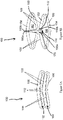
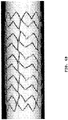
- FIGS. 1A and 1B illustrate exemplary open cells.
- FIG. 1A illustrates two cells 102, 104 of an open cell arrangement in a collapsed state, the open cell segment having two full struts 106 and four half struts 108.
- FIG. 1B illustrates the open cell of FIG. 1A in an expanded state.
- FIGS. 1A and 1B are referred to as "open" cells because of the gap 110 formed between the end portions 112 of the half struts 108 of each cell.
- This gap 110 is an opening between the two cells 102, 104.
- closed cell arrangements typically include arrangements where each cell includes a complete closed periphery around an open area. If the gap were closed in FIGS. 1A and 1B , the segment would include two closed cells.
- the cells of Figures 5B and of U.S. Patent No. 6,488,702 illustrate closed cells.
- the end portions 112 of the half struts 108 can interact (or coaptate) when an additional compressive force is exerted on the stent such that the stent cell is able to be collapsed to a greater degree.
- This can beneficially decrease the profile diameter of a stent comprising a plurality of open cells.
- Coaptation between the end portions of the half struts occurs when the end portions of the half struts are forced into contact with one another by radially compressing the stent so that they are "locked” or engaged together enabling the stent to be collapsed to a greater extent.
- the coaptation essentially reduces the amount of spring back or recoil of the cell when the radially compressive external force is removed.
- the expandable, bistable open cell design incorporates the following features:
- FIG. 2A illustrates an embodiment of an open cell structure 200, as comprised in a lumen support according to the present invention.
- two connected open cells 202, 204 are shown in FIG. 2A , with the cells being shown in the as manufactured state (i.e., before being crimped onto the delivery apparatus).
- FIG. 2B is an enlargement of a portion of the open cells in FIG. 2A , defined by the dashed rectangle.
- the end portion 226, 228 of each pair of the respective thin struts 216 and thick struts 218 defines an angled surface, i.e., the first angled surface 222 and second angled surface 224.
- the gap 210 between the first angled surface 222 and the second angle surface 224 can allow the open cells 202, 204 to collapse to a greater extent when they are crimped onto the stent delivery apparatus.
- the first and second angled surfaces 224, 226 can be angled to control the direction that the respective end portions move during at least during the initial portion or phase of expansion of the open cells, thereby increasing predictability and repeatability of the struts and cells during cell expansion.
- the angle of the first and second angled surfaces 222, 224 in the embodiment shown in FIG. 2B can cause the first end portion 226 to move in the direction indicated by arrow A1, at least during the initial portion or phase of expansion.
- portions of the first angled surface 222 or the second angled surface 224 can be configured to longitudinally overlap portions of the second angled surface 224 or the first angled surface 222, respectively, at least when the open cell is in a collapsed configuration.
- the second angled surface 224 can have a more pronounced second end portion 228 that overlaps the first angled surface at least when the open cell is in a collapsed configuration.
- the increased angle of the second angled surface 224 can improve the ability of the first angled surface 222 of the first end portion 226 to slip off of the second angled surface 224 during expansion of the open cells.
- angles of the first and second angled surfaces 222, 224 can be configured to contribute to a reduction in recoil or spring back of the stent when the stent is crimped on the stent delivery device.
- the end portions 226, 228 releasably engage with or coaptate against one another (as mentioned above) when crimped so that such end portions are releasably held together by the friction and tensile forces of each of the end portions so that such end portions are inhibited from moving apart, thereby holding the cells in a more collapsed position or state.
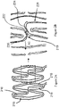
- FIG. 3A is a plan view of the manufacturing pattern for an embodiment of a stent.
- the stent embodiment illustrated in FIG. 3A has one or more first annular segments A and one or more second annular segments B longitudinally arranged in an alternating pattern.
- the annular segments A, B comprise a plurality of open cells and are connected to adjacent annular segments A, B with one or more connectors.
- the cells and/or segments A, B are circumferentially offset relative to one another.
- one or more of the open cells in segment B can be positioned so that a peak of one or more (or all) of the open cells is generally aligned with a valley of one or more (or all) of the open cells of Segment A.
- the cells and/or segments A, B can be generally circumferentially aligned relative to one another so that, for example, the peaks of segment A generally align with the peaks of segment B.
- the connectors of this embodiment or any other embodiment disclosed herein can be linear, curved, severable, substantially non-severable or otherwise, or can comprise any combination of linear, curved, or angled portions or elements.
- the connectors have a linear shape, and can be arranged to define an obtuse angle relative to a longitudinal axis LA defined by the stent.
- the connectors can be arranged so as to connect with the open cells at positions or points that are not directly on the center of the peaks or apices of the open cells. Stated another way, the connectors can be positioned off-peak.
- the connectors can be positioned at the peak of the apices.
- the connectors can have a linear shape and can be arranged so as to be generally parallel with the longitudinal axis LA of the stent.
- the second angled surface can project in an axial direction to a greater extent than the first angled surface so as to longitudinally overlap the first end portion to a greater extent as compared to the overlap provided by the first end portion or first angle surface.
- the orientation of the second angled surface relative to the first angled surface can alternate from one segment A, B to the next (as illustrated), or from one cell to the next.
- FIG. 3B illustrates a stent embodiment having the pattern illustrated in FIG. 3A , showing the stent in an expanded state.
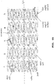
- FIG. 4A is a plan view of the manufacturing pattern for another embodiment of a stent.
- the stent embodiment illustrated in FIG. 4A has one or more annular segments A, B longitudinally arranged in an alternating pattern.
- the annular segments A, B comprise a plurality of open cells and can be connected to adjacent annular segments A, B with one or more connectors.
- the open cells can be similarly configured and similarly oriented from one segment A, B to the next segment A, B.
- the linearly adjacent cells and/or segments A are circumferentially offset relative to one another.
- one or more of the open cells in segment B can be positioned so that a peak of one or more (or all) of the open cells is slightly circumferentially offset with respect to an adjacent peak of one or more (or all) of the open cells of Segment A.
- the cells and/or segments A, B can be generally circumferentially aligned relative to one another so that, for example, the peaks of segment A generally align with the peaks of segment B.
- the connectors can be linear, curved, or otherwise, or can comprise any combination of linear, curved, or angled portions or elements. As illustrated, the connectors have a linear shape, and can be arranged to define an obtuse angle relative to a longitudinal axis LA defined by the stent. Further, the connectors can be arranged so as to connect with the open cells at positions or points that are not directly on the center of the peaks or apices of the open cells. Stated another way, the connectors can be positioned off-peak. In some embodiments, the connectors can be positioned at the peak of the apices. In some embodiments, the connectors can have a linear shape and can be arranged so as to be generally parallel with the longitudinal axis LA of the stent.
- the second angled surface can be project in an axial direction to a greater extent than the first angled surface so as to longitudinally overlap the first end portion to a greater extent as compared to the overlap provided by the first end portion or first angle surface.
- the orientation of the second angled surface relative to the first angled surface can alternate from one segment A, B to the next (as illustrated), or from one cell to the next.
- FIG. 4B illustrates a stent embodiment having the pattern illustrated in FIG. 4A , showing the stent in an expanded state.
- the stent embodiment illustrated in FIG. 4B can be expanded so that the connectors and some of the struts generally align in a spine like arrangement.
- each cell can have at least one rigid strut and one more-flexible strut (i.e., one thick strut and one thin strut).
- the cell can be configured such that the end points of the flexible, thin strut(s) are substantially constrained such that the thin strut is caused to expand through an inflection point that permits the thin strut to self-expand (or be expanded with a lesser force) from the inflection point to a stable expanded state.
- the portion of the thin strut facing the open area of each cell has a convex shape in the collapsed state, and has a concave shape in the expanded state (shown in FIG. 1B ).
- the flexible strut passes through the inflection point at which point the thin strut requires a reduced force to further expand to the expanded state.
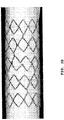
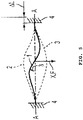
- FIG. 5 which is Fig. 1B from the '702 patent
- a force F is applied to the strut to change it from the convex position (position 2) to the concave position (position 3).
- the solid line position of the strut i.e., position 1) shows the strut at approximately the inflection point position where any additional force will cause the strut to continue to expand automatically or with reduced force to position 3. All positions between position 2 and position 3 are unstable.
- a stent having a plurality of these open cells arranged in a circumferential direction can be expanded from a stable collapsed state using an expansion balloon or other expansion means through the inflection point after which the stent cells will expand to the stable expanded state with little or no force.
- the cell can then be plastically deformed to a second expanded state that has a larger size than the stable expanded state.
- the stent can be plastically collapsed from the stable collapsed state to a second collapsed state by exerting a radial force on the stent when the stent is in the stable collapsed state, so that the profile of the stent is even smaller.
- Certain examples described herein are directed to systems, methods, and apparatuses to treat stenosis, lesions, or other defects in blood vessels, including, but not limited to, the aorta, iliac arteries or veins, coronary arteries, femoral arteries, thoracic arteries, and/or the superficial femoral artery, to name a few.
- the systems, methods, and apparatuses may have application to other vessels or areas of the body such as biliary vessels or ducts, or to other fields, and such additional applications are intended to form a part of this disclosure.
Landscapes
- Health & Medical Sciences (AREA)
- Engineering & Computer Science (AREA)
- Biomedical Technology (AREA)
- Heart & Thoracic Surgery (AREA)
- Life Sciences & Earth Sciences (AREA)
- Cardiology (AREA)
- Oral & Maxillofacial Surgery (AREA)
- Transplantation (AREA)
- Veterinary Medicine (AREA)
- Vascular Medicine (AREA)
- Public Health (AREA)
- Animal Behavior & Ethology (AREA)
- General Health & Medical Sciences (AREA)
- Optics & Photonics (AREA)
- Physics & Mathematics (AREA)
- Gastroenterology & Hepatology (AREA)
- Pulmonology (AREA)
- Prostheses (AREA)
- Media Introduction/Drainage Providing Device (AREA)
Description
- The present disclosure relates to expandable devices, such as, for example, stents, other medical devices, and other medical and non-medical lumen support devices. More particularly, to expandable devices having open cells.
- The present disclosure relates to expandable devices for use in supporting a passageway. While not limited to medical applications only, this disclosure specifically contemplates medical uses such as a vascular prosthesis, commonly referred to as s stent.
- Stents are now widely used in interventional cardiovascular procedures for treating narrowed regions within coronary arteries, and other vessels. Such stent devices generally have a tubular shape and are deployed in a vessel to restore and maintain the patency of a segment of a vessel which has become partially occluded by plaque, and is deployed into the vessel after the occluded region has been reopened by use of a catheter having an expandable dilatation balloon.
- Until recently, previously-known vascular stent prostheses have been either "self-expanding" or "plastically-deformable" devices. While stents are frequently deployed after performing a percutaneous transluminal coronary angioplasty (PTCA) procedure to dilate occluded coronary arteries, efforts have also been made to use such stent devices for treatment of occlusive peripheral vascular disease, such as for carotid arteries, renal arteries and superficial femoral arteries. However, stents used for such peripheral applications frequently require a different set of structural characteristics than those typically used in cardiac stenting. The present disclosure offers several improvements over self-expanding and plastically-deformable stents, not only with respect to the flexibility of the stent implant over known devices, but also as to improved ease of delivery and deployment.
-
U.S. Patent No. 4,733,665 to Palmaz discloses two types of plastically-deformable stents (e.g., stents typically formed of relatively inelastic metals, such as stainless steel, cobalt chromium, etc.), which are delivered within the vasculature via a balloon catheter, onto which the stent is mounted for deployment by balloon expansion. The stents described in Palmaz are constructed from a wire mesh tube or a slotted metal tube. These stents are crimped around the deflated balloon of a delivery catheter to prevent premature release from the catheter while being introduced into the vessel location being treated. Deployment of these stents is accomplished by inflating the balloon at high pressure to expand the tubular device to a predetermined diameter through plastic deformation until it approximates the desired dimension of the patent vascular lumen being treated. Since plastically-deformable stents are typically formed of relatively inelastic metal alloys (such as stainless steel or cobalt chromium), they tend to provide less flexibility than self-expanding stents formed of more elastic materials (such as nitinol). Consequently, plastically-deformable stents are considered generally inappropriate for deployment into blood vessels that are subject to recurring forces associated with compression and elongation, as well as torsional forces, or other forms of dynamic loading. While plastically-deformable stents generally provide adequate radial strength, such stents typically also have a high degree of axial rigidity. Thus, plastically-deformable stents should not be employed in vessels that routinely experience longitudinal shape changes, because the stents lack flexibility to conform to the vessel, and may fracture, deform or cause dissection of the vessel. - Over the past several years, much effort has been expended attempting to design plastically-deformable stents having strut arrangements with flexible axial connectors or links which permit adjacent circumferential rings of a plastically-deformable stent to provide improved longitudinal flexibility, so that the stent will more readily bend and articulate to conform to the particular shape of a vessel during delivery and upon implant. Examples of various plastically-deformable stents with improved articulating properties are found in
U.S. Patent No. 5,195,984 to Schatz .U.S. Patent No. 5,514,154 to Lau et al. , andU.S. Patent No. 6,723,119 to Pinchasik et al. However, reliance upon such articulating links does not entirely solve the issues with respect to fatigue and fracture. In other words, plastically-deformable stents typically incorporate metal alloys which are inherently limiting with respect to the amount of bending tolerated before the material work-hardens and fractures. Plastically-deformable stents not only suffer from the above limitations, but also present an expanded structure with very limited resilience. Consequently, such stents are not deemed to be suitable for use in vessels that may be subject to high radially-compressive forces, such as the carotid arteries, which might abruptly collapse due to a sudden blow or other pressure to the neck. - Another design approach which has been practiced with plastically-deformable stents, with limited success to improve the longitudinal flexibility of the stent, is the use of expandable stent cells which are open, rather than closed. However, there is always been a difficult tradeoff between cell size and cell density, such that the relative ratio of metal struts in contact with the artery wall being supported cannot be reduced to the point that the stent either fails to provide adequate radial strength, or sufficient vascular wall coverage to prevent ingress of vascular tissue between the adjacent struts and into the vascular lumen (i.e., tissue prolapse).
- For this reason, among others, self-expanding stents have been a primary focus for stent development for vascular applications with dynamic loading. Examples of such self-expanding stents include various mesh-like tubes (such as described in
U.S. Patent No. 4,655,771 to Wallsten ), tubes formed of resilient materials (such as zig-zag stainless steel struts described inU.S. Patent No. 4,580,568 to Gianturco ), and tubes formed of superelastic shape memory materials such as nitinol (such as described inU.S. Patent No. 6,306,141 to Jervis ). However, self-expanding stents also suffers certain shortcomings. Mesh-like stents, as well as coiled and zig-zag stents described above, generally fail to provide a high degree of crush resistance or radial strength, and may tend to migrate from their initial deployment site. Additionally, the catheter delivery systems required for most self-expanding stents usually require a proximally-retractable constraining sheath, which tends to make the delivery systems larger in diameter and less flexible, thus limiting access to smaller vasculature and preventing treatment of more distal vascular blockages or lesions. - Significantly, a new type of stent prosthesis has been recently introduced, based upon the concept of a "bistable cell." The bistable cell is described in
U.S. Patent No. 6,488,702 to Besselink . The bistable cell comprises a first strut respectively joined at each of its ends to adjacent ends of a second strut which is relatively more flexible than the first, relatively rigid strut (e.g., the first strut can have a greater width than that of the second strut), thereby forming a closed cell which is defined by the enclosed area bounded by the first and second struts. The bistable cell design is such that it will operate as a spring between only two stable configurations, namely, a stable collapsed (unexpanded) configuration and a stable expanded configuration. A stent which is formed with conventional bistable cells will thus comprise a plurality of interconnected, closed bistable cells. When subjected to a radial force applied outwardly upon the interior surface of such a stent, the relatively flexible second strut will gradually deflect outwardly away from the more rigid first strut, until reaching a transition point where it will abruptly move in a spring-like fashion to a stable expanded position. Consequently, the bistable cell is unstable at any position intermediate the stable collapsed and expanded configuration. - Since this bistable cell is also collapsible by application of a force onto the outer surface of such a stent, directed in an inward radial direction, the stable expanded configuration can be reversibly moved into a stable collapsed configuration. Consequently, it is possible to practice this bistable cell design with much less regard to material properties, and generally permits the use of several metal alloys with varied properties of elasticity, elongation and tensile strength, such as stainless steel, cobalt alloys, nitinol alloys, and even polymers. Interestingly, this bistable cell design permits, for the first time, the ability of stents formed out of shape memory alloys such as nitinol to be crimped onto a balloon for retention until delivery to the vascular site. Since it is no longer necessary to use a delivery catheter provided with a retractable constraining sheath with retraction mechanisms for delivery of nitinol stents, it is now possible to deploy such bistable nitinol stents using catheters having a reduced profile and increased flexibility, and thus treat more tortuous anatomy and more distal lesions.
- However, it has been generally been believed that the bistable cell design would optimally require a closed cell structure. Surprisingly, however, the present disclosure has proven that the full benefits of a bistable cell design can still be practiced with an open cell design, namely a cell which consist of at least two lobes within the cell boundary, wherein the multi-lobed open cell comprises more than a single pair of relatively rigid and relatively flexible struts. Consequently, this unique open-cell embodiment of the bistable cell provides significant improvement in the overall flexibility of the stent, thereby facilitation greater ease of catheter delivery into tortuous anatomy, as well as treatment of more difficult vascular conditions throughout the entire cardiovascular / peripheral system.
-
WO2008/049120 describes lumen support devices having plastically deformable structures including one or more plastically deformable cells having two stable configurations. In one embodiment a device includes one or more open unit cells which may have a predetermined stable expanded configuration and a predetermined stable collapsed configuration. -
US2005/0004650 (Randolf Von Oepen ) describes a stent comprising a tubular flexible body having a wall with a web structure that is expandable from a contracted delivery configuration to deployed configuration. The web structure comprises a plurality of neighboring web patterns, where each web patterns is composed of adjoining webs, and the web patterns are interconnected by transition sections. Each adjoining web comprises a central section interposed between two lateral sections to form concave or convex configurations. A delivery system for the stent is also described. -
US2003/0176914 (Dmitry J Rabkin et al ) describes a molecular stent comprising at least one stent module including an intermediate segment consisting of one of either a closed-cell segment of a Z-segment and a pair of end segments connected to respective longitudinal ends of said intermediate segment, each end segment consisting of the other of said closed-cell segment of Z-segment, each closed-cell segment consisting solely of at least one annular closed-cell ring and each Z-segment consisting solely of at least one annular Z-ring. In addition there is described a method of manufacturing a stent from a small diameter tube including laser-cutting the small diameter tube to define a plurality of longitudinally adjacent Z-rings, providing interconnector portions of said tube integrally joining facing aligned or offset Z-rings, expanding the small diameter tube, and removing predetermined interconnector portions from the expanded tube to provide the predetermined desired arrangement of interconnected closed-cell rings and Z-rings.WO99/39660 (Maurice Roussigne et al -
DE 10 2007 019 772 (Kirsi Schuessler et al ) describes a stent with a tubular grid structure including struts and cell openings formed by the struts wherein in the expanded state of the stent the grid structure has a certain outer diameter DA in mm and the struts each have certain length L in mm, the outer diameter DA of the stent and the length L of the struts being in a certain ratio. - According to a first aspect of the present invention there is provided a lumen support as claimed in claims 1 to 7.
- Some examples described herein are directed to an expandable stent structure, comprising a first relatively stiff portion with a dome-like structure having terminal inward hinges connected to two relatively flexible portions, that in turn are hinged in the opposite direction outward forming an inward apex into the cell and this continuation of the inward apex transitions to a relatively stiff structure ultimately connecting to another inverted dome-like long flexible portion. The stiff to flexible structure continues to alternate until a ring is formed. The inward pointing apex between the longer thick and thin alternating segments are designed to interact with each other during crimping and expansion to allow energy to be stored and released during transition points. The stent further comprises a second relatively stiff portion having first and second ends and a second relatively flexible portion connected to the first and second ends of the first relatively stiff portion, and an opening formed through the first relatively stiff portion and the second relatively flexible portion such that the opening connects the first and second open areas, thereby creating first and second intermediate ends of the first relatively stiff portion and first and second intermediate ends of the second relatively flexible portion. The first relatively stiff portion and the first relatively flexible portion can substantially surround a first open area of the stent structure, and the first relatively stiff portion and the first relatively flexible portion can substantially surround a second open area of the stent structure. The first intermediate end of the relatively stiff portion is connected to the first intermediate end of the relatively flexible portion so as to create a first inward apex, and the second intermediate end of the relatively stiff portion can be connected to the second intermediate end of the relatively flexible portion so as to create a second inward apex. The stent structure is configured such that, in a collapsed configuration, the first inward apex can be in contact with the second inward apex and, in an expanded configuration, the first inward apex can be biased to move in a first circumferential direction and the second inward apex can be biased to move in a second circumferential direction that can be different than the first circumferential direction.
- Some examples described herein are directed to an expandable stent structure, comprising a first relatively stiff portion having first and second ends and a first relatively flexible portion connected to the first and second ends of the first relatively stiff portion, a second relatively stiff portion having first and second ends and a second relatively flexible portion connected to the first and second ends of the first relatively stiff portion, and an opening formed through the first relatively stiff portion and the second relatively flexible portion such that the opening connects the first and second open areas, thereby creating first and second intermediate ends of the first relatively stiff portion and first and second intermediate ends of the second relatively flexible portion. The first relatively stiff portion and the first relatively flexible portion can substantially surround a first open area of the stent structure, and the first relatively stiff portion and the first relatively flexible portion can substantially surround a second open area of the stent structure. The first intermediate end of the relatively stiff portion is connected to the first intermediate end of the relatively flexible portion so as to create a first inward apex, and the second intermediate end of the relatively stiff portion can be connected to the second intermediate end of the relatively flexible portion so as to create a second inward apex. The stent structure is configured such that, in a collapsed configuration, the first inward apex can be in contact with the second inward apex and, in an expanded configuration, the first inward apex can be biased to move in a first circumferential direction (at least during the initial portion or phase of expansion) and the second inward apex can be biased to move in a second circumferential direction (at least during the initial portion or phase of expansion) that can be different than the first circumferential direction.
- Some examples described herein are directed to an expandable stent structure, comprising a first relatively stiff portion having first and second ends and a first relatively flexible portion connected to the first and second ends of the first relatively stiff portion, the first relatively stiff portion and the first relatively flexible portion substantially surrounding a first open area of the stent structure, a second relatively stiff portion having first and second ends and a second relatively flexible portion connected to the first and second ends of the first relatively stiff portion, the first relatively stiff portion and the first relatively flexible portion substantially surrounding a second open area of the stent structure, and an opening formed through the first relatively stiff portion and the second relatively flexible portion such that the opening connects the first and second open areas, thereby creating first and second intermediate ends of the first relatively stiff portion and first and second intermediate ends of the second relatively flexible portion.
- The first intermediate end of the relatively stiff portion is connected to the first intermediate end of the relatively flexible portion so as to create a first inward apex, and the second intermediate end of the relatively stiff portion can be connected to the second intermediate end of the relatively flexible portion so as to create a second inward apex. The first inward apex can have a shape that can be different than a shape of the second inward apex.
- Some embodiments disclosed herein are directed to a lumen support having a plurality of stable configurations, the lumen support comprising one or more annular segments longitudinally oriented in an alternating pattern, wherein the one or more annular segments, comprise at least two open cells, each open cell comprising a first strut having a first and a second end portion, a second strut having a first and a second end portion, a first pair of half struts positioned between and connected to the first end potion of the first strut and the first end portion of the second strut, the first pair of half struts positioned between and connected to the first end portion of the first strut and the first end portion of the second strut, the first pair of half struts defining a first inward facing apex, and a second pair of half struts positioned between the second end potion of the first strut and the second end portion of the second strut, the second pair of half struts defining a second inward facing apex that can be adjacent to the first inward facing apex. The inward facing apices each define an angled surface wherein the direction of the surface is angled with respect to the axial and to the circumferential direction of the lumen support, and the angle of the angled surface of the first inward facing apex can be parallel to the angle of the angled surface of the second inward facing apex wherein the at least two open cells of one annular segment are connected by a connector to at least two open cells of another adjacent segment so that they are circumferentially offset relative to each other. In some embodiments, each open cell can be configured to move between at least a first stable collapsed configuration and a first stable expanded configuration, there being no stable configurations between the first stable collapsed configuration and the first stable expanded configuration. In some embodiments, the lumen support can be configured such that, in a collapsed state, the inward apices are abutting and in an expanded state, the end portions move in opposite circumferential directions (at least during the initial portion or phase of expansion).
- Some embodiments disclosed herein are directed to a lumen support having a plurality of stable configurations, the lumen support comprising at least two open cells, each open cell comprising a first strut having a first and a second end portion, a second strut having a first and a second end portion, a first pair of half struts positioned between the first and second full struts, the first pair of half struts defining a first inward facing apex, and a second pair of half struts positioned between the first and second full struts, the second pair of half struts defining a second inward facing apex that can be adjacent to the first inward facing apex. The inward facing apices each define an angled surface. A portion of the second inward facing apex longitudinally overlaps a portion of the first inward facing apex when the open cell is in a collapsed position.
- Some examples described herein are directed to a method of supporting a passageway with an expandable structure, wherein the expandable structure can comprise a first inward facing apex, a second inward facing apex, the second inward facing apex that can be adjacent to but oppositely oriented relative to the first inward facing apex when the expandable structure is in a collapsed configuration, and a first member and a second member surrounding the first and second inward facing apices. The method comprises positioning the expandable structure in a passageway in a collapsed configuration and radially expanding the expandable structure and thereby moving the first inward facing apex in a first circumferential direction (at least during the initial portion or phase of expansion) and moving the second inward facing apex in a second circumferential direction (at least during the initial portion or phase of expansion) that is different than the first circumferential direction.
- Further advantages and embodiments will become evident from the attached drawings.
- In the drawings:
-
FIGS. 1 A and 1B show an exemplary expandable open cell; -
FIGS. 2A and 2B show an expandable open cell according to various aspects of the disclosure; -
FIGS. 3A and3B show an expandable device consistent with various aspects of the disclosure; -
FIGS. 4A and4B show an expandable device consistent with various aspects of the disclosure; and -
FIG. 5 shows an exemplary prior art bi-stable cell. - The embodiments described herein relate to
expandable devices 100, such as, for example, stents, other medical devices, and other medical and non-medical lumen support devices, having open cells. In some embodiments, the devices can be configured for release of stored energy during expansion related to eversion of the coapted dome and crimping when the inward apices coapt and move though an inversion point. Exemplary open cells are illustrated inFIGS. 1A and 1B. FIG. 1A illustrates twocells full struts 106 and four half struts 108.FIG. 1B illustrates the open cell ofFIG. 1A in an expanded state. - The cells illustrated in
FIGS. 1A and 1B are referred to as "open" cells because of thegap 110 formed between theend portions 112 of the half struts 108 of each cell. Thisgap 110 is an opening between the twocells FIGS. 1A and 1B , the segment would include two closed cells. For example, the cells of Figures 5B and ofU.S. Patent No. 6,488,702 illustrate closed cells. - In the collapsed state (as in
FIG. 1A ), theend portions 112 of the half struts 108 can interact (or coaptate) when an additional compressive force is exerted on the stent such that the stent cell is able to be collapsed to a greater degree. This can beneficially decrease the profile diameter of a stent comprising a plurality of open cells. Coaptation between the end portions of the half struts occurs when the end portions of the half struts are forced into contact with one another by radially compressing the stent so that they are "locked" or engaged together enabling the stent to be collapsed to a greater extent. The coaptation essentially reduces the amount of spring back or recoil of the cell when the radially compressive external force is removed. - For example, referring to
FIG. 1A , the expandable, bistable open cell design incorporates the following features: - a first relatively stiff portion (152) having first and second ends and a first relatively flexible portion (154) connected to the first and second ends of the first relatively stiff portion, the first relatively stiff portion and the first relatively flexible portion substantially surrounding a first open area (156) of the stent structure;
- a second relatively stiff portion (158) having first and second ends and a second relatively flexible portion (160) connected to the first and second ends of the first relatively stiff portion, the first relatively stiff portion and the first relatively flexible portion substantially surrounding a second open area (162) of the stent structure; and
- an opening (110) formed through the first relatively stiff portion and the second relatively flexible portion such that the opening connects the first and second open areas, thereby creating first and second intermediate ends (152a, 152b) of the first relatively stiff portion and first and second intermediate ends (160a, 160b) of the second relatively flexible portion;
- wherein:
- the first intermediate end (152a) of the relatively stiff portion is connected to the first intermediate end (160a) of the relatively flexible portion so as to create a first inward apex (170),
- the second intermediate end (152b) of the relatively stiff portion is connected to the second intermediate end (160b) of the relatively flexible portion so as to create a second inward apex (172), and
- the stent structure is configured such that, in a collapsed configuration, the first inward apex (170) is in contact with the second inward apex (172) and, in an expanded configuration, the first inward apex is biased to move in a first circumferential direction and the second inward apex is biased to move in a second circumferential direction that is different than the first circumferential direction.
-
FIG. 2A illustrates an embodiment of an open cell structure 200, as comprised in a lumen support according to the present invention. In particular, two connected open cells 202, 204 are shown inFIG. 2A , with the cells being shown in the as manufactured state (i.e., before being crimped onto the delivery apparatus).FIG. 2B is an enlargement of a portion of the open cells inFIG. 2A , defined by the dashed rectangle. - With reference to
FIG. 2B , theend portion thin struts 216 andthick struts 218 defines an angled surface, i.e., the firstangled surface 222 and secondangled surface 224. In some embodiments, thegap 210 between the firstangled surface 222 and thesecond angle surface 224 can allow the open cells 202, 204 to collapse to a greater extent when they are crimped onto the stent delivery apparatus. Additionally, the first and secondangled surfaces - In particular, the angle of the first and second
angled surfaces FIG. 2B can cause thefirst end portion 226 to move in the direction indicated by arrow A1, at least during the initial portion or phase of expansion. Further, in some embodiments, portions of the firstangled surface 222 or the secondangled surface 224 can be configured to longitudinally overlap portions of the secondangled surface 224 or the firstangled surface 222, respectively, at least when the open cell is in a collapsed configuration. For example, with reference toFIG. 2B , the secondangled surface 224 can have a more pronouncedsecond end portion 228 that overlaps the first angled surface at least when the open cell is in a collapsed configuration. In some embodiments, the increased angle of the secondangled surface 224 can improve the ability of the firstangled surface 222 of thefirst end portion 226 to slip off of the secondangled surface 224 during expansion of the open cells. - Further, the angles of the first and second
angled surfaces end portions -
FIG. 3A is a plan view of the manufacturing pattern for an embodiment of a stent. According to the invention, the stent embodiment illustrated inFIG. 3A has one or more first annular segments A and one or more second annular segments B longitudinally arranged in an alternating pattern. The annular segments A, B comprise a plurality of open cells and are connected to adjacent annular segments A, B with one or more connectors. - According to the invention, as illustrated, the cells and/or segments A, B are circumferentially offset relative to one another. For example, with reference to
FIG. 3A , one or more of the open cells in segment B can be positioned so that a peak of one or more (or all) of the open cells is generally aligned with a valley of one or more (or all) of the open cells of Segment A. Alternatively (not according to the present invention), the cells and/or segments A, B can be generally circumferentially aligned relative to one another so that, for example, the peaks of segment A generally align with the peaks of segment B. - The connectors of this embodiment or any other embodiment disclosed herein can be linear, curved, severable, substantially non-severable or otherwise, or can comprise any combination of linear, curved, or angled portions or elements. As illustrated, the connectors have a linear shape, and can be arranged to define an obtuse angle relative to a longitudinal axis LA defined by the stent. Further, the connectors can be arranged so as to connect with the open cells at positions or points that are not directly on the center of the peaks or apices of the open cells. Stated another way, the connectors can be positioned off-peak. In some embodiments, the connectors can be positioned at the peak of the apices. In some embodiments, the connectors can have a linear shape and can be arranged so as to be generally parallel with the longitudinal axis LA of the stent.
- Also, with reference to
FIG. 3A , similar to some other stent embodiments disclosed herein, in some embodiments, the second angled surface can project in an axial direction to a greater extent than the first angled surface so as to longitudinally overlap the first end portion to a greater extent as compared to the overlap provided by the first end portion or first angle surface. Additionally, in some embodiments, the orientation of the second angled surface relative to the first angled surface can alternate from one segment A, B to the next (as illustrated), or from one cell to the next. -
FIG. 3B illustrates a stent embodiment having the pattern illustrated inFIG. 3A , showing the stent in an expanded state. -
FIG. 4A is a plan view of the manufacturing pattern for another embodiment of a stent. According to the invention, the stent embodiment illustrated inFIG. 4A has one or more annular segments A, B longitudinally arranged in an alternating pattern. The annular segments A, B comprise a plurality of open cells and can be connected to adjacent annular segments A, B with one or more connectors. In contrast with the stent embodiment illustrated inFIGS. 3A ,3B , the open cells can be similarly configured and similarly oriented from one segment A, B to the next segment A, B. - According to the invention, as illustrated, the linearly adjacent cells and/or segments A are circumferentially offset relative to one another. For example, with reference to
FIG. 4A , one or more of the open cells in segment B can be positioned so that a peak of one or more (or all) of the open cells is slightly circumferentially offset with respect to an adjacent peak of one or more (or all) of the open cells of Segment A. Alternatively (not illustrated), the cells and/or segments A, B can be generally circumferentially aligned relative to one another so that, for example, the peaks of segment A generally align with the peaks of segment B. - The connectors can be linear, curved, or otherwise, or can comprise any combination of linear, curved, or angled portions or elements. As illustrated, the connectors have a linear shape, and can be arranged to define an obtuse angle relative to a longitudinal axis LA defined by the stent. Further, the connectors can be arranged so as to connect with the open cells at positions or points that are not directly on the center of the peaks or apices of the open cells. Stated another way, the connectors can be positioned off-peak. In some embodiments, the connectors can be positioned at the peak of the apices. In some embodiments, the connectors can have a linear shape and can be arranged so as to be generally parallel with the longitudinal axis LA of the stent.
- Also, with reference to
FIG. 4A , similar to some other stent embodiments disclosed herein, in some embodiments, the second angled surface can be project in an axial direction to a greater extent than the first angled surface so as to longitudinally overlap the first end portion to a greater extent as compared to the overlap provided by the first end portion or first angle surface. Additionally, in some embodiments, the orientation of the second angled surface relative to the first angled surface can alternate from one segment A, B to the next (as illustrated), or from one cell to the next. -
FIG. 4B illustrates a stent embodiment having the pattern illustrated inFIG. 4A , showing the stent in an expanded state. As can be seen, the stent embodiment illustrated inFIG. 4B can be expanded so that the connectors and some of the struts generally align in a spine like arrangement. - Additionally, one or more of the cells of any of the embodiments disclosed herein can be configured to have (without limitation) bistable or transition point technology (also referred to as inflection point), as described in
U.S. Patent No. 6,488,702 . Briefly stated, in such embodiments, each cell can have at least one rigid strut and one more-flexible strut (i.e., one thick strut and one thin strut). The cell can be configured such that the end points of the flexible, thin strut(s) are substantially constrained such that the thin strut is caused to expand through an inflection point that permits the thin strut to self-expand (or be expanded with a lesser force) from the inflection point to a stable expanded state. - In particular, with reference to
FIG. 1A , the portion of the thin strut facing the open area of each cell has a convex shape in the collapsed state, and has a concave shape in the expanded state (shown inFIG. 1B ). Between the collapsed, convex shape and the expanded, concave shape, the flexible strut passes through the inflection point at which point the thin strut requires a reduced force to further expand to the expanded state. - This is shown schematically in
FIG. 5 (which isFig. 1B from the '702 patent) Here, a force F is applied to the strut to change it from the convex position (position 2) to the concave position (position 3). The solid line position of the strut (i.e., position 1) shows the strut at approximately the inflection point position where any additional force will cause the strut to continue to expand automatically or with reduced force to position 3. All positions between position 2 and position 3 are unstable. - A stent having a plurality of these open cells arranged in a circumferential direction can be expanded from a stable collapsed state using an expansion balloon or other expansion means through the inflection point after which the stent cells will expand to the stable expanded state with little or no force. The cell can then be plastically deformed to a second expanded state that has a larger size than the stable expanded state. Additionally, the stent can be plastically collapsed from the stable collapsed state to a second collapsed state by exerting a radial force on the stent when the stent is in the stable collapsed state, so that the profile of the stent is even smaller.
- Certain examples described herein are directed to systems, methods, and apparatuses to treat stenosis, lesions, or other defects in blood vessels, including, but not limited to, the aorta, iliac arteries or veins, coronary arteries, femoral arteries, thoracic arteries, and/or the superficial femoral artery, to name a few. However, the systems, methods, and apparatuses may have application to other vessels or areas of the body such as biliary vessels or ducts, or to other fields, and such additional applications are intended to form a part of this disclosure. And, while specific embodiments may be described herein with regard to particular portions of a person's vasculature, it is to be understood that the embodiments described can be adapted for use in other portions of a person's or animal's vasculature or other portions of the body and are not limited to the specific blood vessels specified herein.
- Although the inventions have been disclosed in the context of a certain preferred embodiments and examples, it will be understood by those skilled in the art that the present inventions extend beyond the specifically disclosed embodiments to other alternative embodiments and still fall within the scope of the inventions, as defined by the appended claims. For example, in some embodiments, the features, configurations, or other details disclosed are combinable with other features, configurations, or details disclosed herein with respect to other connector or stent embodiments to form new embodiments not explicitly disclosed herein.
- It will be apparent to those skilled in the art that various modifications and variations can be made to the expandable devices of the present disclosure without departing from the scope of the invention, as defined by the dependent claims. Throughout the disclosure, use of the terms "a," "an," and "the" may include one or more of the elements to which they refer. Other embodiments of the invention will be apparent to those skilled in the art from consideration of the specification and practice of the invention disclosed herein. It is intended that the specification and examples be considered as exemplary only.
Claims (7)
- A lumen support (100) having a plurality of stable configurations, the lumen support comprising:
one or more first annular segments and one or more second annular segments longitudinally arranged in an alternating pattern, wherein the annular segments comprise at least two open cells, each open cell comprising:a first strut (106) having a first and a second end portion,a second strut (106) having a first and a second end portion,a first pair of half struts (108) positioned between and connected to the first end portion of the first strut and the first end portion of the second strut, the first pair of half struts defining a first inward facing apex (170), anda second pair of half struts (108) positioned between and connected to the second end portion of thefirst strut and the second end portion of the second strut, the second pair of half struts defining a second inward facing apex (172) that is adjacent to the first inward facing apex,characterised in thatthe inward facing apices each define an angled surface (222, 224), wherein the direction of the surface is angled with respect to the axial and to the circumferential direction of the lumen support, andthe angled surface of the first inward facing apex is parallel to the angled surface of the second inward facing apex;wherein the at least two open cells of adjacent annular segments are connected by a connector so that they are circumferentially offset relative to each other. - The lumen support of claim 1, wherein the first inward facing apex (170) has a shape that is different than a shape of the second inward facing apex (172).
- The lumen support of claim 1, wherein each open cell is configured to move between at least a first stable collapsed configuration and a first stable expanded configuration, there being no stable configurations between the first stable collapsed configuration and the first stable expanded configuration.
- The lumen support of claim 1, wherein the lumen support is configured such that, in a collapsed state, the inward apices are abutting and in an expanded state, the end portions move in opposite circumferential directions.
- The lumen support of claim 1, wherein a portion of the second inward facing apex longitudinally overlaps a portion of the first inward facing apex when the open cell is in a collapsed position.
- The lumen support of claim 1, wherein the connector is chosen from linear, curved, severable, or non-severable.
- The lumen support of claim 1, wherein the angled surface of the second inward facing apex projects in an axial direction to a greater extent than the angled surface of the first inward facing apex.
Applications Claiming Priority (2)
| Application Number | Priority Date | Filing Date | Title |
|---|---|---|---|
| US37833010P | 2010-08-30 | 2010-08-30 | |
| PCT/US2011/049804 WO2012030871A1 (en) | 2010-08-30 | 2011-08-30 | Expandable devices |
Publications (2)
| Publication Number | Publication Date |
|---|---|
| EP2611397A1 EP2611397A1 (en) | 2013-07-10 |
| EP2611397B1 true EP2611397B1 (en) | 2022-06-29 |
Family
ID=44759756
Family Applications (1)
| Application Number | Title | Priority Date | Filing Date |
|---|---|---|---|
| EP11752450.4A Active EP2611397B1 (en) | 2010-08-30 | 2011-08-30 | Expandable devices |
Country Status (4)
| Country | Link |
|---|---|
| US (2) | US9358139B2 (en) |
| EP (1) | EP2611397B1 (en) |
| CA (1) | CA2809981C (en) |
| WO (1) | WO2012030871A1 (en) |
Families Citing this family (1)
| Publication number | Priority date | Publication date | Assignee | Title |
|---|---|---|---|---|
| WO2019246268A1 (en) * | 2018-06-20 | 2019-12-26 | W. L. Gore & Associates, Inc. | Support structure for an implantable device with enhanced compressive stiffness region(s) |
Family Cites Families (16)
| Publication number | Priority date | Publication date | Assignee | Title |
|---|---|---|---|---|
| SE445884B (en) | 1982-04-30 | 1986-07-28 | Medinvent Sa | DEVICE FOR IMPLANTATION OF A RODFORM PROTECTION |
| US5190546A (en) | 1983-10-14 | 1993-03-02 | Raychem Corporation | Medical devices incorporating SIM alloy elements |
| US4580568A (en) | 1984-10-01 | 1986-04-08 | Cook, Incorporated | Percutaneous endovascular stent and method for insertion thereof |
| US4733665C2 (en) | 1985-11-07 | 2002-01-29 | Expandable Grafts Partnership | Expandable intraluminal graft and method and apparatus for implanting an expandable intraluminal graft |
| CA1322628C (en) | 1988-10-04 | 1993-10-05 | Richard A. Schatz | Expandable intraluminal graft |
| CA2079417C (en) | 1991-10-28 | 2003-01-07 | Lilip Lau | Expandable stents and method of making same |
| EP1656892A3 (en) | 1997-01-24 | 2006-05-31 | Paragon Intellectual Properties, LLC | Expandable device comprising bistable unit cells |
| ES2290995T3 (en) | 1997-09-24 | 2008-02-16 | Med Institute, Inc. | RADIALLY EXPANDABLE ENDOPROTESIS. |
| WO1999039660A1 (en) | 1998-02-03 | 1999-08-12 | B. Braun Celsa | Prosthesis with undulating longitudinal braces |
| US6682554B2 (en) | 1998-09-05 | 2004-01-27 | Jomed Gmbh | Methods and apparatus for a stent having an expandable web structure |
| US6723119B2 (en) | 2000-03-01 | 2004-04-20 | Medinol Ltd. | Longitudinally flexible stent |
| US6579310B1 (en) * | 2000-08-17 | 2003-06-17 | Advanced Cardiovascular Systems, Inc. | Stent having overlapping struts |
| US20030176914A1 (en) | 2003-01-21 | 2003-09-18 | Rabkin Dmitry J. | Multi-segment modular stent and methods for manufacturing stents |
| US8105373B2 (en) * | 2002-12-16 | 2012-01-31 | Boston Scientific Scimed, Inc. | Flexible stent with improved axial strength |
| WO2008049120A1 (en) | 2006-10-21 | 2008-04-24 | Nexeon Medsystems, Inc. | Deformable lumen support devices and methods of use |
| DE102007019772B4 (en) | 2007-04-26 | 2019-09-26 | Acandis Gmbh | Stent and method of making a stent |
-
2011
- 2011-08-30 CA CA2809981A patent/CA2809981C/en active Active
- 2011-08-30 WO PCT/US2011/049804 patent/WO2012030871A1/en active Application Filing
- 2011-08-30 US US13/819,846 patent/US9358139B2/en active Active
- 2011-08-30 EP EP11752450.4A patent/EP2611397B1/en active Active
-
2016
- 2016-05-02 US US15/144,056 patent/US9717608B2/en active Active
Also Published As
| Publication number | Publication date |
|---|---|
| WO2012030871A1 (en) | 2012-03-08 |
| US20160250046A1 (en) | 2016-09-01 |
| US20140012364A1 (en) | 2014-01-09 |
| EP2611397A1 (en) | 2013-07-10 |
| US9717608B2 (en) | 2017-08-01 |
| US9358139B2 (en) | 2016-06-07 |
| CA2809981A1 (en) | 2012-03-08 |
| CA2809981C (en) | 2019-02-12 |
Similar Documents
| Publication | Publication Date | Title |
|---|---|---|
| JP5259746B2 (en) | Lumen prosthesis | |
| US9592137B2 (en) | Flexible stent | |
| US9585779B2 (en) | Segmented scaffold designs | |
| US8337544B2 (en) | Endoprosthesis having flexible connectors | |
| EP1903999B1 (en) | Controlled fracture connections for stents | |
| US20080172123A1 (en) | Bifurcated stent | |
| JPH11221288A (en) | Prosthesis with multiple bridge type joint part for endoscopic operation and operation thereof | |
| US8343211B2 (en) | Connectors for bifurcated stent | |
| AU2007243708A1 (en) | Fracture-resistant helical stent incorporating bistable cells and methods of use | |
| EP0969777A1 (en) | Coiled sheet stent having helical articulation and methods of use | |
| JP2009505775A (en) | Stent with expanding side branch configuration | |
| EP2088963B1 (en) | Bifurcation stent design with over expansion capability | |
| US10842654B2 (en) | Stent with segments capable of uncoupling during expansion | |
| US20080281395A1 (en) | Ratcheting bio cell designs | |
| US9717608B2 (en) | Expandable devices | |
| US7691142B2 (en) | Stent | |
| KR101015329B1 (en) | Surgical stent | |
| EP3315100B1 (en) | Stent with segments capable of uncoupling during expansion |
Legal Events
| Date | Code | Title | Description |
|---|---|---|---|
| PUAI | Public reference made under article 153(3) epc to a published international application that has entered the european phase |
Free format text: ORIGINAL CODE: 0009012 |
|
| 17P | Request for examination filed |
Effective date: 20130228 |
|
| AK | Designated contracting states |
Kind code of ref document: A1 Designated state(s): AL AT BE BG CH CY CZ DE DK EE ES FI FR GB GR HR HU IE IS IT LI LT LU LV MC MK MT NL NO PL PT RO RS SE SI SK SM TR |
|
| DAX | Request for extension of the european patent (deleted) | ||
| 17Q | First examination report despatched |
Effective date: 20160714 |
|
| STAA | Information on the status of an ep patent application or granted ep patent |
Free format text: STATUS: EXAMINATION IS IN PROGRESS |
|
| STAA | Information on the status of an ep patent application or granted ep patent |
Free format text: STATUS: EXAMINATION IS IN PROGRESS |
|
| STAA | Information on the status of an ep patent application or granted ep patent |
Free format text: STATUS: EXAMINATION IS IN PROGRESS |
|
| REG | Reference to a national code |
Ref country code: DE Ref legal event code: R079 Ref document number: 602011073058 Country of ref document: DE Free format text: PREVIOUS MAIN CLASS: A61F0002900000 Ipc: A61F0002915000 |
|
| GRAP | Despatch of communication of intention to grant a patent |
Free format text: ORIGINAL CODE: EPIDOSNIGR1 |
|
| STAA | Information on the status of an ep patent application or granted ep patent |
Free format text: STATUS: GRANT OF PATENT IS INTENDED |
|
| RIC1 | Information provided on ipc code assigned before grant |
Ipc: A61F 2/915 20130101AFI20211221BHEP |
|
| INTG | Intention to grant announced |
Effective date: 20220119 |
|
| GRAS | Grant fee paid |
Free format text: ORIGINAL CODE: EPIDOSNIGR3 |
|
| GRAA | (expected) grant |
Free format text: ORIGINAL CODE: 0009210 |
|
| STAA | Information on the status of an ep patent application or granted ep patent |
Free format text: STATUS: THE PATENT HAS BEEN GRANTED |
|
| AK | Designated contracting states |
Kind code of ref document: B1 Designated state(s): AL AT BE BG CH CY CZ DE DK EE ES FI FR GB GR HR HU IE IS IT LI LT LU LV MC MK MT NL NO PL PT RO RS SE SI SK SM TR |
|
| REG | Reference to a national code |
Ref country code: GB Ref legal event code: FG4D |
|
| REG | Reference to a national code |
Ref country code: CH Ref legal event code: EP |
|
| REG | Reference to a national code |
Ref country code: DE Ref legal event code: R096 Ref document number: 602011073058 Country of ref document: DE |
|
| REG | Reference to a national code |
Ref country code: AT Ref legal event code: REF Ref document number: 1500809 Country of ref document: AT Kind code of ref document: T Effective date: 20220715 |
|
| REG | Reference to a national code |
Ref country code: IE Ref legal event code: FG4D |
|
| PGFP | Annual fee paid to national office [announced via postgrant information from national office to epo] |
Ref country code: NL Payment date: 20220826 Year of fee payment: 12 |
|
| REG | Reference to a national code |
Ref country code: LT Ref legal event code: MG9D |
|
| PG25 | Lapsed in a contracting state [announced via postgrant information from national office to epo] |
Ref country code: SE Free format text: LAPSE BECAUSE OF FAILURE TO SUBMIT A TRANSLATION OF THE DESCRIPTION OR TO PAY THE FEE WITHIN THE PRESCRIBED TIME-LIMIT Effective date: 20220629 Ref country code: NO Free format text: LAPSE BECAUSE OF FAILURE TO SUBMIT A TRANSLATION OF THE DESCRIPTION OR TO PAY THE FEE WITHIN THE PRESCRIBED TIME-LIMIT Effective date: 20220929 Ref country code: LT Free format text: LAPSE BECAUSE OF FAILURE TO SUBMIT A TRANSLATION OF THE DESCRIPTION OR TO PAY THE FEE WITHIN THE PRESCRIBED TIME-LIMIT Effective date: 20220629 Ref country code: HR Free format text: LAPSE BECAUSE OF FAILURE TO SUBMIT A TRANSLATION OF THE DESCRIPTION OR TO PAY THE FEE WITHIN THE PRESCRIBED TIME-LIMIT Effective date: 20220629 Ref country code: GR Free format text: LAPSE BECAUSE OF FAILURE TO SUBMIT A TRANSLATION OF THE DESCRIPTION OR TO PAY THE FEE WITHIN THE PRESCRIBED TIME-LIMIT Effective date: 20220930 Ref country code: FI Free format text: LAPSE BECAUSE OF FAILURE TO SUBMIT A TRANSLATION OF THE DESCRIPTION OR TO PAY THE FEE WITHIN THE PRESCRIBED TIME-LIMIT Effective date: 20220629 Ref country code: BG Free format text: LAPSE BECAUSE OF FAILURE TO SUBMIT A TRANSLATION OF THE DESCRIPTION OR TO PAY THE FEE WITHIN THE PRESCRIBED TIME-LIMIT Effective date: 20220929 |
|
| PGFP | Annual fee paid to national office [announced via postgrant information from national office to epo] |
Ref country code: LU Payment date: 20220829 Year of fee payment: 12 Ref country code: IE Payment date: 20220829 Year of fee payment: 12 Ref country code: GB Payment date: 20220829 Year of fee payment: 12 Ref country code: ES Payment date: 20220901 Year of fee payment: 12 Ref country code: DK Payment date: 20220829 Year of fee payment: 12 Ref country code: DE Payment date: 20220829 Year of fee payment: 12 Ref country code: AT Payment date: 20220803 Year of fee payment: 12 |
|
| REG | Reference to a national code |
Ref country code: NL Ref legal event code: MP Effective date: 20220629 |
|
| REG | Reference to a national code |
Ref country code: AT Ref legal event code: MK05 Ref document number: 1500809 Country of ref document: AT Kind code of ref document: T Effective date: 20220629 |
|
| PG25 | Lapsed in a contracting state [announced via postgrant information from national office to epo] |
Ref country code: RS Free format text: LAPSE BECAUSE OF FAILURE TO SUBMIT A TRANSLATION OF THE DESCRIPTION OR TO PAY THE FEE WITHIN THE PRESCRIBED TIME-LIMIT Effective date: 20220629 Ref country code: LV Free format text: LAPSE BECAUSE OF FAILURE TO SUBMIT A TRANSLATION OF THE DESCRIPTION OR TO PAY THE FEE WITHIN THE PRESCRIBED TIME-LIMIT Effective date: 20220629 |
|
| PGFP | Annual fee paid to national office [announced via postgrant information from national office to epo] |
Ref country code: MC Payment date: 20220804 Year of fee payment: 12 Ref country code: IS Payment date: 20220802 Year of fee payment: 12 Ref country code: FR Payment date: 20220825 Year of fee payment: 12 Ref country code: BE Payment date: 20220829 Year of fee payment: 12 |
|
| PG25 | Lapsed in a contracting state [announced via postgrant information from national office to epo] |
Ref country code: NL Free format text: LAPSE BECAUSE OF FAILURE TO SUBMIT A TRANSLATION OF THE DESCRIPTION OR TO PAY THE FEE WITHIN THE PRESCRIBED TIME-LIMIT Effective date: 20220629 |
|
| PGFP | Annual fee paid to national office [announced via postgrant information from national office to epo] |
Ref country code: CH Payment date: 20220905 Year of fee payment: 12 |
|
| PG25 | Lapsed in a contracting state [announced via postgrant information from national office to epo] |
Ref country code: SM Free format text: LAPSE BECAUSE OF FAILURE TO SUBMIT A TRANSLATION OF THE DESCRIPTION OR TO PAY THE FEE WITHIN THE PRESCRIBED TIME-LIMIT Effective date: 20220629 Ref country code: SK Free format text: LAPSE BECAUSE OF FAILURE TO SUBMIT A TRANSLATION OF THE DESCRIPTION OR TO PAY THE FEE WITHIN THE PRESCRIBED TIME-LIMIT Effective date: 20220629 Ref country code: RO Free format text: LAPSE BECAUSE OF FAILURE TO SUBMIT A TRANSLATION OF THE DESCRIPTION OR TO PAY THE FEE WITHIN THE PRESCRIBED TIME-LIMIT Effective date: 20220629 Ref country code: PT Free format text: LAPSE BECAUSE OF FAILURE TO SUBMIT A TRANSLATION OF THE DESCRIPTION OR TO PAY THE FEE WITHIN THE PRESCRIBED TIME-LIMIT Effective date: 20221031 Ref country code: ES Free format text: LAPSE BECAUSE OF FAILURE TO SUBMIT A TRANSLATION OF THE DESCRIPTION OR TO PAY THE FEE WITHIN THE PRESCRIBED TIME-LIMIT Effective date: 20220629 Ref country code: EE Free format text: LAPSE BECAUSE OF FAILURE TO SUBMIT A TRANSLATION OF THE DESCRIPTION OR TO PAY THE FEE WITHIN THE PRESCRIBED TIME-LIMIT Effective date: 20220629 Ref country code: AT Free format text: LAPSE BECAUSE OF FAILURE TO SUBMIT A TRANSLATION OF THE DESCRIPTION OR TO PAY THE FEE WITHIN THE PRESCRIBED TIME-LIMIT Effective date: 20220629 |
|
| PGFP | Annual fee paid to national office [announced via postgrant information from national office to epo] |
Ref country code: IT Payment date: 20220923 Year of fee payment: 12 |
|
| PG25 | Lapsed in a contracting state [announced via postgrant information from national office to epo] |
Ref country code: PL Free format text: LAPSE BECAUSE OF FAILURE TO SUBMIT A TRANSLATION OF THE DESCRIPTION OR TO PAY THE FEE WITHIN THE PRESCRIBED TIME-LIMIT Effective date: 20220629 Ref country code: IS Free format text: LAPSE BECAUSE OF FAILURE TO SUBMIT A TRANSLATION OF THE DESCRIPTION OR TO PAY THE FEE WITHIN THE PRESCRIBED TIME-LIMIT Effective date: 20221029 |
|
| REG | Reference to a national code |
Ref country code: DE Ref legal event code: R097 Ref document number: 602011073058 Country of ref document: DE |
|
| PG25 | Lapsed in a contracting state [announced via postgrant information from national office to epo] |
Ref country code: AL Free format text: LAPSE BECAUSE OF FAILURE TO SUBMIT A TRANSLATION OF THE DESCRIPTION OR TO PAY THE FEE WITHIN THE PRESCRIBED TIME-LIMIT Effective date: 20220629 |
|
| PGFP | Annual fee paid to national office [announced via postgrant information from national office to epo] |
Ref country code: MT Payment date: 20220802 Year of fee payment: 12 |
|
| PG25 | Lapsed in a contracting state [announced via postgrant information from national office to epo] |
Ref country code: DK Free format text: LAPSE BECAUSE OF FAILURE TO SUBMIT A TRANSLATION OF THE DESCRIPTION OR TO PAY THE FEE WITHIN THE PRESCRIBED TIME-LIMIT Effective date: 20220629 Ref country code: CZ Free format text: LAPSE BECAUSE OF FAILURE TO SUBMIT A TRANSLATION OF THE DESCRIPTION OR TO PAY THE FEE WITHIN THE PRESCRIBED TIME-LIMIT Effective date: 20220629 |
|
| PLBE | No opposition filed within time limit |
Free format text: ORIGINAL CODE: 0009261 |
|
| STAA | Information on the status of an ep patent application or granted ep patent |
Free format text: STATUS: NO OPPOSITION FILED WITHIN TIME LIMIT |
|
| 26N | No opposition filed |
Effective date: 20230330 |
|
| PG25 | Lapsed in a contracting state [announced via postgrant information from national office to epo] |
Ref country code: SI Free format text: LAPSE BECAUSE OF FAILURE TO SUBMIT A TRANSLATION OF THE DESCRIPTION OR TO PAY THE FEE WITHIN THE PRESCRIBED TIME-LIMIT Effective date: 20220629 |
|
| REG | Reference to a national code |
Ref country code: DE Ref legal event code: R119 Ref document number: 602011073058 Country of ref document: DE |
|
| PG25 | Lapsed in a contracting state [announced via postgrant information from national office to epo] |
Ref country code: MC Free format text: LAPSE BECAUSE OF NON-PAYMENT OF DUE FEES Effective date: 20230831 |
|
| REG | Reference to a national code |
Ref country code: CH Ref legal event code: PL |
|
| PG25 | Lapsed in a contracting state [announced via postgrant information from national office to epo] |
Ref country code: MC Free format text: LAPSE BECAUSE OF NON-PAYMENT OF DUE FEES Effective date: 20230831 Ref country code: HU Free format text: LAPSE BECAUSE OF FAILURE TO SUBMIT A TRANSLATION OF THE DESCRIPTION OR TO PAY THE FEE WITHIN THE PRESCRIBED TIME-LIMIT; INVALID AB INITIO Effective date: 20110830 |
|
| PG25 | Lapsed in a contracting state [announced via postgrant information from national office to epo] |
Ref country code: LU Free format text: LAPSE BECAUSE OF NON-PAYMENT OF DUE FEES Effective date: 20230830 |
|
| GBPC | Gb: european patent ceased through non-payment of renewal fee |
Effective date: 20230830 |
|
| PG25 | Lapsed in a contracting state [announced via postgrant information from national office to epo] |
Ref country code: LU Free format text: LAPSE BECAUSE OF NON-PAYMENT OF DUE FEES Effective date: 20230830 Ref country code: CY Free format text: LAPSE BECAUSE OF FAILURE TO SUBMIT A TRANSLATION OF THE DESCRIPTION OR TO PAY THE FEE WITHIN THE PRESCRIBED TIME-LIMIT Effective date: 20220629 Ref country code: CH Free format text: LAPSE BECAUSE OF NON-PAYMENT OF DUE FEES Effective date: 20230831 |
|
| REG | Reference to a national code |
Ref country code: BE Ref legal event code: MM Effective date: 20230831 |
|
| REG | Reference to a national code |
Ref country code: IE Ref legal event code: MM4A |