EP2602180B1 - Pod drive installation and hull configuration for a marine vessel - Google Patents
Pod drive installation and hull configuration for a marine vessel Download PDFInfo
- Publication number
- EP2602180B1 EP2602180B1 EP13157923.7A EP13157923A EP2602180B1 EP 2602180 B1 EP2602180 B1 EP 2602180B1 EP 13157923 A EP13157923 A EP 13157923A EP 2602180 B1 EP2602180 B1 EP 2602180B1
- Authority
- EP
- European Patent Office
- Prior art keywords
- hull
- pod drive
- pod
- fairing
- platform
- Prior art date
- Legal status (The legal status is an assumption and is not a legal conclusion. Google has not performed a legal analysis and makes no representation as to the accuracy of the status listed.)
- Active
Links
- 238000009434 installation Methods 0.000 title claims description 24
- XLYOFNOQVPJJNP-UHFFFAOYSA-N water Substances O XLYOFNOQVPJJNP-UHFFFAOYSA-N 0.000 description 20
- 230000000694 effects Effects 0.000 description 18
- 230000007704 transition Effects 0.000 description 14
- 230000004048 modification Effects 0.000 description 13
- 238000012986 modification Methods 0.000 description 13
- 230000005540 biological transmission Effects 0.000 description 10
- 230000009977 dual effect Effects 0.000 description 10
- 230000006978 adaptation Effects 0.000 description 6
- 230000008901 benefit Effects 0.000 description 5
- 230000002411 adverse Effects 0.000 description 4
- 239000012530 fluid Substances 0.000 description 4
- 238000000034 method Methods 0.000 description 4
- 238000005096 rolling process Methods 0.000 description 4
- 238000010276 construction Methods 0.000 description 3
- 230000013011 mating Effects 0.000 description 3
- 241000390166 Physaria Species 0.000 description 2
- 230000005465 channeling Effects 0.000 description 2
- 230000005484 gravity Effects 0.000 description 2
- 230000033001 locomotion Effects 0.000 description 2
- 230000001681 protective effect Effects 0.000 description 2
- 230000009467 reduction Effects 0.000 description 2
- 238000013459 approach Methods 0.000 description 1
- 230000015572 biosynthetic process Effects 0.000 description 1
- 244000309464 bull Species 0.000 description 1
- 230000008859 change Effects 0.000 description 1
- 238000006073 displacement reaction Methods 0.000 description 1
- 239000000446 fuel Substances 0.000 description 1
- 230000002452 interceptive effect Effects 0.000 description 1
- 230000007246 mechanism Effects 0.000 description 1
- 230000008569 process Effects 0.000 description 1
- 238000009420 retrofitting Methods 0.000 description 1
- 238000007789 sealing Methods 0.000 description 1
- 230000005641 tunneling Effects 0.000 description 1
Images


Classifications
-
- B—PERFORMING OPERATIONS; TRANSPORTING
- B63—SHIPS OR OTHER WATERBORNE VESSELS; RELATED EQUIPMENT
- B63H—MARINE PROPULSION OR STEERING
- B63H5/00—Arrangements on vessels of propulsion elements directly acting on water
- B63H5/07—Arrangements on vessels of propulsion elements directly acting on water of propellers
- B63H5/16—Arrangements on vessels of propulsion elements directly acting on water of propellers characterised by being mounted in recesses; with stationary water-guiding elements; Means to prevent fouling of the propeller, e.g. guards, cages or screens
-
- B—PERFORMING OPERATIONS; TRANSPORTING
- B63—SHIPS OR OTHER WATERBORNE VESSELS; RELATED EQUIPMENT
- B63B—SHIPS OR OTHER WATERBORNE VESSELS; EQUIPMENT FOR SHIPPING
- B63B39/00—Equipment to decrease pitch, roll, or like unwanted vessel movements; Apparatus for indicating vessel attitude
- B63B39/06—Equipment to decrease pitch, roll, or like unwanted vessel movements; Apparatus for indicating vessel attitude to decrease vessel movements by using foils acting on ambient water
-
- B—PERFORMING OPERATIONS; TRANSPORTING
- B63—SHIPS OR OTHER WATERBORNE VESSELS; RELATED EQUIPMENT
- B63H—MARINE PROPULSION OR STEERING
- B63H5/00—Arrangements on vessels of propulsion elements directly acting on water
- B63H5/07—Arrangements on vessels of propulsion elements directly acting on water of propellers
- B63H5/08—Arrangements on vessels of propulsion elements directly acting on water of propellers of more than one propeller
- B63H5/10—Arrangements on vessels of propulsion elements directly acting on water of propellers of more than one propeller of coaxial type, e.g. of counter-rotative type
-
- B—PERFORMING OPERATIONS; TRANSPORTING
- B63—SHIPS OR OTHER WATERBORNE VESSELS; RELATED EQUIPMENT
- B63H—MARINE PROPULSION OR STEERING
- B63H5/00—Arrangements on vessels of propulsion elements directly acting on water
- B63H5/07—Arrangements on vessels of propulsion elements directly acting on water of propellers
- B63H5/125—Arrangements on vessels of propulsion elements directly acting on water of propellers movably mounted with respect to hull, e.g. adjustable in direction, e.g. podded azimuthing thrusters
- B63H2005/1254—Podded azimuthing thrusters, i.e. podded thruster units arranged inboard for rotation about vertical axis
Definitions
- the present invention relates to a pod drive installation and hull configuration according to the preamble of claim 1.
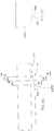
- Pod drive systems for propelling and steering marine vessels, typically comprise of one or more pod drive units wherein, as illustrated in Fig. 1 , each pod drive unit 2A of a pod drive system 2 typically includes an inboard engine 2B which drives a drive shaft 2C that, in turn, drives an inboard transmission unit 2D that is connected to and drives an underwater steerable gearcase 2E that is rotatably mounted through the hull 2F and supports and drives a propeller 2G.
- engine torque is transmitted from a generally horizontal drive shaft 2C, through a first bevel gear assembly 2H, to a generally vertical arranged intermediate drive shaft 2I extending downwardly through inboard transmission unit 2D to the steerable gearcase 2E.
- the engine torque of the vertical intermediate drive shaft 2I is, in turn, transmitted through a second bevel gear assembly 2J to a propeller shaft 2K which, in turn, supports and drives a propeller 2G.
- the pod drive unit 2A allows the propeller 2G to be rotated in the generally horizontal plane, about a steering axis 2L, and through an angular range of, for example, up to 360°, so that the pod drive unit 2A combines and forms both the vessel propulsion function as well as the steering function.
- the selection of the appropriate maximum starboard and port steering angles will depend on the desired steering performances and design constraints and choices, such as the type of vessel, the design and characteristics of the vessel hull and the desired manoeuvring characteristics.
- pod drive systems also referred to as azimuthing propulsion systems or azimuth thrusters
- azimuthing propulsion systems have become popular and common in vessels of all sizes for a number of real and perceived advantages.
- pod drive systems are typically more compact than and offer greater manoeuverability than systems having inboard engines or non-steerable propellers and rudders and are better protected from damage and offer greater manoeuverability than outboard drive systems and many propeller and rudder systems.
- pod drive systems present a number of problems.
- Pod drive systems of various configurations, are used in a wide range of marine vessels ranging from small pleasure craft to large work vessels, such as commercial fishing vessels, and even large ships, such as cruise liners.
- the common problems of installing and using pod drive systems in pleasure craft are illustrative, however, to a greater or lesser degree, of the typically problems associated with using pod drive systems in all types of vessels and will be discussed below as examples of these problems.
- Figs. 2 through 6 are illustrations of various pod drive systems of the prior art as installed in a vessel having a V-bottomed planing hull with twin pod drive units mounted through the hull, as shown in Figs. 2 through 4 , at symmetrical positions on either side of the hull keel or centerline.
- V-bottom hulls, and variations thereof are commonly used on a variety of other vessels, including commercial and work craft, and vessels having rounded or curved bottoms will present similar problems because the pod drive units must be mounted on sections of the hull that are at an angle to both the vertical plane and the horizontal plane. It will also be recognized that at least some of the same or similar problems appear with flat bottomed hulls as well as will be apparent from the following discussion.
- a tunnel pod drive system 2 is shown therein as adopted, for example, by the Brunswick Corporation of Lake Forest, Illinois and described in U.S. Patents Nos. 7,371,140 and 7,188,581 issued to Richard A. Davis for a Protective Marine Vessel and Drive and in European Patent Application Serial No. 1 777 154 A2 filed on September 26, 2006 and published on April 25, 2007, and representing the closest prior art.
- twin pod drive units 2A in the V-bottom hull 4H requires the formation of corresponding open bottomed "tunnels" 4T, or canyons, on either side of the keel 4K with each pod drive unit 2A extending into a corresponding tunnel 4T through the top 40 of the tunnel 4T with underwater steerable gearcases 2E extending vertically below the tunnel top 40 and residing largely within the tunnels 4T.
- the propellers 2G are located partially within or extend largely below the bottom 4B of hull 4H and the steering axes 2L are generally oriented vertically.
- tunnels 4B are typically closed by a forward end wall 4F, for structural reasons, such as reducing the interior volume of hull 4H occupied by the tunnels 4T, while the aft ends 4R of tunnels 4T are open to permit the flow of water through the tunnels 4T and around the steerable gearcases 2E and the propellers 2G.
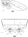
- a primary advantage of a tunnel pod drive system 2, as illustrated in Figs. 2 and 3 is that pod drive units 2A, and in particular steerable gearcases 2E and to a certain extent the propellers 2G, are better protected because pod drive units 2A are raised or recessed vertically, relative to the keel 4K, thereby at least partially protecting pod drive units 2A from striking an underwater object(s).
- Other possible advantages are that the navigational draft of the vessel is typically reduced allowing more water areas to be safely navigated by the vessel, and that steering by the thrust generating elements, that is the propellers 2G, generally allows greater manoeuverability and improved vessel handling characteristics.
- a major disadvantage of a tunnel pod drive system 2 is the effect on hull characteristics caused by modifications to the hull to accommodate the tunnels 4T, particularly when an existing hull is modified for tunnel mounting of pod drive units 2.
- the installation or provision of tunnels 4T not only results in significant structural changes to the hull but also reduces the amount of buoyancy of the vessel, toward the stern end thereof, thus reducing and/or redistributing the buoyancy of the vessel.
- the tunnels 4T have also been found to reduce the planing surface at the stern, thereby causing a "squatting" or “sinking" effect of the stern of the vessel that has been found to increase further in the event that the depth of tunnels 4T within the vessel is increased.
- the "wetted surface area" of the hull 4H is increased by the tunnels 4T, thereby increasing the frictional drag of hull 4H and correspondingly reducing the vessel speed while also increasing fuel consumption.
- the tunnels 4T have also been found to cause redirection of the flow of water around hull 4H, thereby further increasing the drag of the hull 4H. It has been found that the tunnels 4T may channel the flow of water, generated by the propellers 2G, thereby creating low pressure fields that result in a downward force, on the aft region of the hull, that may adversely effect vessel trim angles.
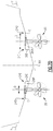
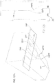
- the pod drive units 2A are mounted directly to hull 4H, in a slanted steering axis pod drive system 4, so that the steering axis 2L of each pod drive unit 2A is normal to the port and the starboard surfaces 4P and 4S of the hull 4H and is thereby at an angle to the vertical axis of the vessel.
- a major advantage of the slanted steering axis pod drive system 4 is that the system does not require any tunnels 4T to adapt the pod drive units 2A to the hull 4H.
- the slanted axis system 4 thereby does not require any significant modification(s) to the shape or the structure of the hull 4H, does not effect or alter the buoyancy or distribution of the buoyancy or the trim of the hull, the fluid flow around the hull, the wetted surface area or the drag of the hull or some of the handling characteristics of the hull and, for example, does not result in low pressure areas in the aft regions of the hull with consequent "squatting" or "sinking" effects.
- the pod drive units of Fig. 4 are, however, more exposed to damage in the slanted axis pod drive system 4, and the system typically results in the pod drive units, and thus the vessel, having an increased draft as compared to a tunnel mount system.
- Yet another aspect of the slanted steering axis pod drive system 4 is that, as can be seen from Fig. 4 , the tilt of steering axes 2L-relative to a substantially vertical axis-results in each pod drive unit 2A producing a vertical component of thrust from the propeller 2G in addition to the horizontal component of thrust.
- the magnitude and direction of the vertical component of thrust depends upon the direction and angle at which the propeller 2G is rotated and the slanted steering axis pod drive systems may be used, for example, to trim the running position of the vessel. That is, the pod drive units 2A may be rotated in opposite directions by an angle of rotation selected so that the horizontal components of the thrusts generated by the two pod units 2A cancel each other while the vertical components of the thrust, generated by each unit, is added to exert an upward or downward force on the stern of the vessel and to thereby adjust the fore/aft trim of the vessel to a desired setting or value.
- the rotations of the two pod drive units may be dynamically adjusted, in this way, to control the fore/aft trim of the vessel for various speeds or loading conditions, and may be used, for example, to adjust the fore/aft trim of the vessel during a transitory period, such as assisting the vessel over the planing threshold when transitioning from the displacement mode to the planing mode.
- the rotation of the pod drive units 2A toward the inside of the turn results in the vertical thrust generated by the inside pod drive unit 2A, that is, the pod drive unit 2A toward the inside of the turn, being directed downward while the vertical thrust component generated by the outside drive pod 2A is directed upward.
- the combined vertical thrust components from the drive pod units 2A, in a slanted steering drive system 4 according to Fig. 4 thereby may exert a force during a turn that causes the vessel to have an unwanted rolling motion toward the inside of the turn. It has been found that this unwanted effect increases with the deadrise of the hull, that is, the angle of rise of the port and the starboard halves of the hull on either side of the keel.
- the rolling effect also places addition constraints on the center of gravity of the vessel because the center of gravity must be kept as low as possible to reduce excessive roll angles, during turns, and in the design of the transom because the height of the transom must be sufficient to accommodate the shift in the waterlines as the vessel rolls during turns.
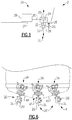
- FIG. 5 is an isometric view of a single tunnel pod drive unit 2A installed in a tunnel 4T extending along the aft keel 4K of the hull 4H. It should be noted that, in Fig. 5 , the pod drive unit 2A shown therein is a "tractor" propulsion unit. That is, the blade pitch of the propeller 2G and the orientation of the steerable gearcase 2E are reversed, with respect to the propellers 2G and the gearcases 2E illustrated in Figs.
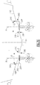
- Fig. 6 is a rear view of the single tunnel pod drive system of Fig. 5 combined with the dual slanted steering axis pod drive system 4 of Fig. 4 to provide a triple pod drive system.
- the gearcase 2E and the propeller 2G are implemented as "pushing" units as shown in Figs. 2 through 4 , rather than a "tractor” or “pulling” unit as illustrated in Fig. 5 .
- the system of Fig. 5 could also be combined with the system of Figs. 2 and 3 to provide an alternate implementation comprising a triple tunnel pod drive system, providing either a pushing or a pulling force. It will be appreciated, however, that all such approaches to the problems of the pod drive systems of the prior art will generally have the same disadvantages as the embodiments illustrated in Figs. 2 through 4 .
- the present invention is directed at addressing and overcoming the above noted problems as well as other problems associated with the known prior art systems.
- the present invention is directed to a pod drive installation for mounting a pod drive unit to a hull of a vessel and hull configurations for mounting of one or more pod drive units to the hull of a vessel.
- a pod drive installation comprises a generally horizontally disposed pod drive platform for supporting a rotational pod drive mount for mounting the pod drive unit with a generally vertically oriented steering axis wherein the pod drive platform has a width which extends generally perpendicular to a keel of the vessel and a length that extends generally parallel to the keel of the vessel so as to accommodate at least the rotational pod drive mount.
- the length of the pod drive platform and the length of one or both of the inboard and output sidewalls extending parallel to the keel of the vessel are typically greater than the width of the pod drive platform.
- the pod drive platform is mounted to the hull outward of the keel of the vessel so that the pod drive platform generally intersects a plane defined by a bottom hull surface tilted from the horizontal at a contour of intersection between an outboard boundary and an inboard boundary of the pod drive platform or at a contour located at or adjacent to either the outboard or inboard boundary of the pod drive platform, and is connected to the bottom hull surface by at least one of an outboard sidewall and an inboard sidewall.
- the pod drive platform, the bottom hull surface and either or both of the outboard sidewall and the inboard sidewall form one, or both, of an outboard protrusion from the bottom hull surface and a recess into the bottom hull surface and either or both of the inboard and outboard sidewalls form a fairing, between the pod drive platform and the bottom hull surface.
- the increase or decrease in hull volume and the wetted surface area, in the region of the pod drive unit or units due to the mounting of the pod drive platform or platforms into the hull, is thereby significantly reduced compared to the volume and wetted surface area of the hull in this region for a bottom hull surface not including the hull drive pod platform or platforms.
- Each pod drive unit may include an inboard propulsion device for driving an inboard transmission unit that drives an underwater steerable gearcase that is rotatably mounted, through the hull, by the rotational pod drive mount to rotate about the steering axis and drive a propeller, and the hull of the vessel is one of a generally V-shaped hull and a hull having a generally curved shape.
- Further aspects of the present invention are directed to configurations of the hull adjacent to and including the pod drive platforms to provide hull contours that minimize disadvantageous effects on the hull, such as, for example, an undesirable reduction in or distribution of buoyancy or trim of the hull, an excessive wetted surface area and consequent drag of the hull, undesirable fluid flow paths around the hull that, for example, result in undesirable low or high pressure areas in the aft regions of the hull, and undesirable handling characteristics.
- the present invention includes hull configurations for the mounting of pod drive installations.
- An embodiment of the present invention includes a "warp" hull configuration for mounting at least a port pod drive unit and a starboard drive unit to a hull of a vessel on port and starboard horizontally disposed pod drive platforms for supporting corresponding respective rotational pod drive mounts for mounting port and starboard pod drive units.
- the warp hull configuration includes a warp fairing for and corresponding to each pod drive platform for fairing each pod drive platform to a corresponding bottom hull surface wherein each warp fairing includes a generally vertical sidewall fairing and a generally horizontal warp surface.
- Each sidewall fairing has an upper boundary defined by an intersection of the sidewall fairing with the warp surface, a lower boundary defined by an intersection of the sidewall fairing with a bottom hull surface, a forward extremity formed by a converging intersection of the upper boundary and lower boundary at the hull surface, and an aft boundary defined by a line of intersection between the sidewall fairing and an inside boundary of the corresponding one of the pod drive platforms at a forward edge of the corresponding pod drive platform.
- Each horizontal warp surface has an inner boundary extending along an intersection of the warp surface and the upper boundary of the sidewall fairing, an boundary extending along an intersection between the warp surface and the forward edge of the corresponding pod drive platform, and an outer boundary extending forward from and in continuation of an outer boundary of the pod drive platform and along the hull surface to a forward boundary of the warp surface, wherein the forward boundary of the warp surface extends transversely from the forward extremity of the sidewall fairing and along the hull surface to the outer boundary of the warp surface.
- each warp surface is curved to tangentially intersect the forward edge of the corresponding pod drive platform and the aft boundary and a forward portion of each warp surface is curved to tangentially intersect the bottom hull surface along the forward boundary of the warp surface.
- horizontal means that the platform is generally horizontal when the vessel is in an upright position and floating, without power, in water such that the pod steering axis is substantially normal to a top surface of the water.
- pod drive unit means a pod drive system which includes an inboard engine, with or without a transmission, that drives a drive shaft which, in turn, drives an inboard transmission unit that is connected to and drives an underwater steerable gearcase, rotatably mounted through the hull, which supports and drives a propeller.
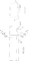
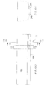
- FIGs. 7A and 7B diagrammatic rear and bottom views of the pod drive installations 10 of the pod drive units 12, of an exemplary pod drive system 14 as implemented for a V-bottom hull 16H of a vessel 18, are shown although it will be appreciated, in view of the following description, that the pod drive system 10 may be similarly implemented, for example, in vessels having rounded or curved bottom hulls as well.
- the exemplary pod drive system 10 includes two pod drive units 12-each of which is similar to the design illustrated in Fig. 1 -typically comprises an inboard engine (not shown) driving a drive shaft (not shown) that drives an inboard transmission unit (not shown) that is connected to and drives an underwater steerable gearcase 2E that is rotatably mounted through the hull 16H which supports and drives a propeller 2G.
- an inboard engine not shown
- a drive shaft not shown
- an inboard transmission unit not shown
- an underwater steerable gearcase 2E that is rotatably mounted through the hull 16H which supports and drives a propeller 2G.
- engine torque is transmitted from generally horizontal drive shaft and through a first bevel gear assembly to a generally vertical intermediate drive shaft extending downwardly between inboard transmission unit and the steerable gearcase 2E, wherein the torque drives the vertical intermediate drive shaft (now shown) and is transmitted through a second bevel gear assembly (not shown) to the propeller shaft which supports and drives the propeller 2G, with propeller 2G being rotatable about vertical steering axis 2L.
- the propellers 2G of the port and the starboard pod drive units 12 are, in a presently preferred embodiment, counter-rotating propellers so as to avoid the generation of any turning torque on the vessel 18, as is often found in marine drive systems having symmetrically located port and starboard propulsion units or propellers.
- the deadrise angle of V-bottom hull 16H in the illustrated embodiment, is, for example, approximately 15.5°, but may be any angle in the conventional deadrise angle range of 0° to 26°.
- the steerable gearcase 2E of each pod drive unit 12 is rotatably mounted upon and through a rotational pod mount 22 that includes the necessary structural and mechanical elements, including sealing elements necessary to support the rotating steerable gearcase 2E and the associated steering and drive elements of the pod drive unit 12 to and through the hull 16H, as described herein above with reference to Fig. 1 .
- the structural requirements of the rotational pod mount 22, and the means and structural elements by which a steerable gearcase 2E and the associated drive elements are mounted to and through such a rotational pod mount 22 and sealed against leakage, are well known to those of ordinary skill in the arts and, as such, are not described in any further detail herein.
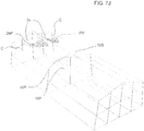
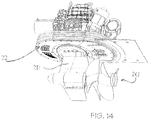
- FIG. 14 An exemplary implementation of the rotational pod mount 22 is illustrated in Fig. 14 and described in U.S. Patent Application Publication No. 2007/0224892 published September 27, 2007 and U.S. Patent Publication No. 2007/0093150 published April 26, 2007, both by Davis for a Protective Marine Vessel and Drive, as well as in similar references.
- the rotational pod mount 22, and thereby the pod drive unit 12 is mounted to a horizontally oriented pod drive platform 24 with one or more pod drive platforms 24 being positioned symmetrically, on either side of the keel 16K, on each of the port and the starboard hull surfaces 16P and 16S of the bottom of the hull 16H so that the steering axis 2L, for each pod drive unit 12, is substantially vertically oriented.
- each pod drive platform 24 has a horizontal width D along the platform dimension which extends perpendicular to the keel 16K, that is across hull 16H, such that the width D is at least equal to or greater than the diameter of rotational pod mount 22 and is sufficient to at least accommodate and support the rotating steerable gearcase 2E and associated steering and drive elements of the pod drive unit 12.
- Each pod drive platform 24 also has a horizontal length, along the platform dimension which extends parallel to the keel 16K (see Fig.
- the pod length L 1 is equal to or greater than the diameter of the rotational pod mount 22 and at least a section of the longitudinal length is sufficiently long and horizontally flat so as to at least accommodate and support rotating steerable gearcase 2E and any associated steering and drive elements of the pod drive unit 12.
- the total length L T of recess or cut out is also sufficiently long enough to "fair" the pod drive platform 24 into either the port or the starboard bottom hull surfaces 16P and 16S of the hull 16H, as described below in further detail.
- each pod drive platform 24 is positioned along the width of the corresponding one of the port hull surface 16P and the starboard hull surface 16S so that the horizontal plane, formed by the pod drive platform 24, intersects an inclined plane P, formed and defined by the corresponding one of the port bottom hull surface 16P and the starboard bottom hull surface 16S. As shown in Figs. 7A , 7C , 7D and 7D1 , each pod drive platform 24 is positioned along the width of the corresponding one of the port hull surface 16P and the starboard hull surface 16S so that the horizontal plane, formed by the pod drive platform 24, intersects an inclined plane P, formed and defined by the corresponding one of the port bottom hull surface 16P and the starboard bottom hull surface 16S. As shown in Figs.
- the line or contour of intersection C, between the pod drive platform 24 and the corresponding one of the port hull surface 16P and the starboard hull surface 16S may be located at any point between the inboard and the outboard boundaries 24I and 24O of the pod drive platform 24, depending upon the location of the pod drive platform 24.
- the contour of intersection C may be a straight line or may also be, depending upon the shape and curvature of the bottom of the hull and the shape and/or orientation of the pod drive platform 24, a curved edge, a curved arc, a rounded or curved segment, etc.
- Fig. 7A illustrates an installation wherein the contour of intersection C is located at approximately the mid-point of the width D of the pod drive platform 24 and extends generally parallel to the keel 16K.
- Fig. 7C illustrates a case in which the contour of intersection C is located at or adjacent to the inboard extremities 24I of the pod drive platforms 24, while Figs. 7D and 7D1 illustrate installations wherein the contour of intersection C is located at or adjacent to the outboard extremities 24O of the pod drive platforms 24.
- the relationship of the pod drive platform 24, relative to the port and the starboard bottom hull surfaces 16P and 16S, will result in the pod drive platform 24 mating or joining with the port and the starboard bottom hull surfaces 16P and 16S by at least one of a wedge shaped outboard protrusion 26P and/or a wedge shaped inboard recess 26R, or both, relative to hull surfaces 16P and 16S, and depending on the contour of intersection C formed between pod drive platform 24 and the bottom hull surfaces 16P and 16S.
- a wedge shaped outboard protrusion 26P and/or a wedge shaped inboard recess 26R or both
- the pod drive platform 24 will, in this case, include and be connected to the port and the starboard bottom hull surfaces 16P and 16S by inboard and outboard sidewalls 26I and 260, forming respective wedge shaped outboard protrusions 26P from the hull surfaces 16P and 16S as well as respective wedge shaped inboard recesses 26R into the hull surfaces 16P and 16S.
- the pod drive platforms 24 will include and be connected with the port and the starboard bottom hull surfaces 16P and 16S by either wedge shaped outboard protrusions 26P from the hull surfaces 16P and 16S formed by outboard sidewalls 26O, as illustrated in Fig. 7C , or wedge shaped inboard recesses 26R into the hull surfaces 16P and 16S formed by inboard sidewalls 26I, as illustrated in Figs. 7D and 7D1 .
- Figs. 7A , 7C , 7D and 7D1 that the increase or decrease in hull volume and the wetted surface area of the hull, in the region of the pod drive unit or units due to the mounting of the pod drive platform or platforms into the hull, is thereby significantly reduced compared to the volume and wetted surface area of the hull in this region for a bottom hull surface not including the hull drive pod platform or platforms.
- a pod drive platform 24 or pod drive platforms 24, relative to bottom hull surface 16P and 16S may be displaced vertically by a relatively small amount, as compared to the positions shown in Figs. 7A , 7C , 7D and 7D1 , where such modifications in the vertical position of the pod drive platforms 24 are minor compared to the vertical positions of systems of the prior art, as described with reference to Figs. 1 , 3 and 5 for example.
- Such adaptations may be necessary or desirable for a number of reasons, such as an adaptation to internal structures of the hull or to reduce the protrusion of elements of a pod drive unit 2A, such as steerable gearcase 2E, into the water flow paths in the region of a pod drive system 2 with consequent unwanted disturbances in the water flow around the hull and pod drive units 12 in this region.
- Fig. 7D1 a brief discussion concerning the minor variation of this embodiment will now be discussed.
- the embodiment of Fig. 7D1 is substantially identical to the embodiment of Fig. 7D .
- identical elements are given identical reference numerals.
- each pod drive platform 24 may slope downwardly toward the keel 16K to form an angle of generally between about 1 and about 15 degrees-an angle of 15 degrees is depicted in Fig. 7D1 .
- the inboard transmission units 2D do not extend vertically upwardly (distance VD in Fig.
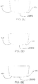
- Figs. 7B , 7E and 7F are, in turn, diagrammatic bottom plan views illustrating the general configurations and relationships of inboard and outboard sidewalls 26I and 26O and the contours of the port and starboard bull bottom surfaces.
- either or both of the inboard and the outboard side walls 26I and 26O form a fairing 26F integrating the pod drive platform 24 into the contours of the bottom hull surfaces 16P and 16S to allow for the optimum flow of water over the exterior bottom surfaces 16P and 16S of the hull 16H and the pod drive platforms 24, depending upon the position of pod drive platform 24 along the width of the port and the starboard bottom hull surfaces 16P and 16S.
- pod drive platform 24 and the inboard and the outboard sidewalls 26I and 26O will, in each case, be generally terminated by the plane of the transom of hull 16H, the general manner of the exemplary implementations of the pod drive systems is illustrated, for example, in Figs. 2 through 6 .
- the adaptation of pod drive systems and the pod drive platforms, to hulls having rounded or curved bottoms, will be well understood by and be apparent to those of ordinary skill in the relevant arts.
- each pod drive platform 24 has a horizontal width D along the platform dimension which extends perpendicular to the keel 16K, that is across hull 16H, such that the width D is at least equal to or greater than the diameter of rotational pod mount 22 to be installed and is sufficient to at least accommodate and support a rotating steerable gearcase (not shown) and associated steering and drive elements of the pod drive unit 12.
- Each pod drive platform 24 has a horizontal length L 1 , along the platform dimension, which extends parallel to the keel 16K which is longitudinal along the longitudinal length of the keel 16K of the hull 16H, wherein the length L 1 is equal to or greater than the length diameter of the rotational pod mount to be installed and is sufficient to at least accommodate and support rotating steerable gearcase and associated steering and drive elements of the pod drive unit 12 such that the exterior surface of the pod drive unit 12 is flush with the bottom surface of the vessel 18.
- the total length L T of the recess or cut out for the pod drive platform 24 is also sufficient to facilitate fairing the pod drive platform 24 into the port and the starboard bottom hull surfaces 16P and 16S of the hull 16H, as described herein.
- each pod drive platform 24 is positioned along the width of a corresponding one of the port hull surface 16P and the starboard hull surface 16S so that the horizontal plane, formed by the pod drive platform 24, intersects an inclined plane P, generally formed and defined by a corresponding one of the port bottom hull surface 16P and the starboard bottom hull surface 16S.
- the contour of intersection C, between the pod drive platform 24 and the corresponding one of the port hull surface 16P and the starboard hull surface 16S is generally a curved edge.
- the relationship of the pod drive platform 24, relative to the port and the starboard bottom hull surfaces 16P and 16S, will result in the pod drive platform 24 mating or joining with the respective port and the starboard bottom hull surfaces 16P and 16S so as to form a wedge shaped inboard recess 26R relative to the port and the starboard hull surfaces 16P and 16S.
- the perimeter of the pod drive platform 24, both along the leading bow end thereof and along the outer port or outer starboard side of the pod drive platform 24, has a smooth and gradual transition or fairing with the port or the starboard bottom hull surfaces 16P and 16S of the vessel 18.
- the perimeter of the pod drive platform 24, adjacent the keel 16K of the vessel 18, generally has a more abrupt transition with the bottom hull surfaces 16P and 16S of the vessel 18. That is, an angle of between 90 and 150, typically about 120 degrees or so, is formed between the pod drive platform 24 and the inboard sidewall 26I (see Fig. 7G ).
- the outboard perimeter edge of the pod drive platform 24 forms a fairing 26F which smoothly integrates the exposed, exterior surface of the pod drive unit 12, following installation thereof, with the bottom hull surfaces 16P and 16S so as to allow for the optimum flow of water over the exterior bottom surfaces 16P and 16S of the hull 16H and exterior surface of the pod drive unit 12.
- the pod drive platform 24 may be recessed further into the hull of the vessel 18 to ensure that the exterior surface of the pod drive unit 12, following installation thereof, precisely merges with and forms an exterior contour for the vessel 18 which results in the desired water flow characteristics along the bottom of the vessel 18 with minimal drag.
- the aft end of the pod drive platform 24 and the inboard sidewalls 26I will, in each case, be generally terminated by the plane of the transom T of hull 16H, general in the manner illustrated in Figs. 2 through 6 , for example.
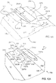
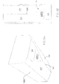
- the overall shape of the cut-out is developed using a V-shaped angled section V (comprising a horizontal leg and an inclined leg) for creating the wedge shaped cut-out in the hull 16H (see Fig. 7L ).
- V-shaped angled section V is passed through the hull of the vessel 18 to determine the overall perimeter of the cut-out to be formed within the hull 16H.
- the orientation of the V-shaped angled section V, relative to the hull 16H does not change, i.e., the V-shaped angled section is merely gradually moved vertically away from the hull as the V-shaped angled section V is moved from the stern toward the bow of the vessel 18. That is, the orientation of the V-shaped angled section V, relative to the hull, always remains constant so that horizontal leg always remains in a horizontal orientation.
- the associated incremental transitions I, determined by the V-shaped angled section V can be seen in Fig. 7L .
- the V-shaped angled section initially passes longitudinally along the hull 16H, from the stern toward the bow, generally without any vertical movement of the V-shaped angled section V away from the hull 16H for a sufficient distance, at least equal to the desired longitudinal length of the horizontal pod drive platform 24, to form a horizontal and flat surface for accommodating the pod drive unit. Thereafter, the V-shaped angled section V commences its gradual vertical incremental transition away from the hull, e.g., for each small increment I that the V-shaped angled section V moves longitudinally toward the bow of the vessel 18, the V-shaped angled section V is also gradually moved vertically incrementally I away from the hull 16H and these incremental transitions I are diagrammatically shown in Fig. 7L . The incremental transitions I are spaced quite close to one another, adjacent a leading bow end of the cutout, but are spaced slightly further away from one another adjacent the stern end of the vessel 18.
- the cutout is designed so as to form a flat region or area, which may included a shouldered radii, and allow the pod drive unit 12 to mounted in a flush fashion within this recess so that the exterior surface of the pod drive unit 12 merges with and forms a smooth transition with the exterior surface of the hull to provide the desired efficient water flow characteristics along the bottom surface of the vessel 18, as generally shown in Fig. 14 .
- the desired depth and/or offset of the V-shaped angled section V may be altered due to the deadrise angle and/or twist of the hull.
- the V-shaped angled section V may be shifted or moved forward, toward the bow of the vessel 18, to provide a longer straight section, i.e., a longer horizontal pod drive platform 24, adjacent the transom of the vessel 18.
- a longer straight section, or a longer pod drive platform 24, is generally required when a drive, for the vessel 18, is shifted or moved forward for some reason, e.g., to avoid interfering with a raked transom or a hydraulic swim platform.
- Such shift toward the bow, and away from the transom of the vessel 18, is generally on the order of between about 45.7 to 76.2 cm (18 to 30 inches).
- FIGs. 8A , 9A-9G , 10A-10G and 11A-11G and to Figs. 12A and 13A-13G therein are shown a diagrammatic illustrations of additional embodiments of hull configurations for the mounting of pod platforms of pod drive systems to minimize disadvantageous effects on the hull such as, for example, an undesirable reduction in or distribution of buoyancy or trim of the hull, an excessive wetted surface area and consequent drag of the hull, undesirable fluid flow paths around the hull that, for example, result in undesirable low or high pressure areas in the aft regions of the hull, and undesirable handling characteristics.
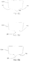
- a "delta" hull configuration 28 for mounting two separate spaced apart pod drive units (not shown in these Figures), generally one on either side of the keel 16K of a vessel 18, is illustrated.
- the delta hull configuration 28 includes a pair of generally planar horizontal pod drive mounting platforms 24 that each extend, by a width W, normal to the keel 16K and extend longitudinally along the keel 16K, by a distance L, where width W and length L are at least adequate in size so as to form first and second pod drive platforms 24A and 24B, located on either side of keel 16K, for mounting of the pod drive units 2A at the desired locations on either side of keel 16K.
- the first and the second pod drive platforms 24A and 24B are coincident with one another and define a pod drive mounting plane 24P.
- An aft edge of the pod drive mounting plane 24P, and thus of the pod drive platforms 24A and 24B, is generally located at the aft end of the hull 16H while a forward end of drive mounting plane 24P, and thus of the pod drive platforms 24A and 24B, is a located along a fairing inflection line 26FL that extends generally perpendicular to the keel 16K and comprises the start of a generally planar delta fairing 26FD.
- the delta fairing 26FD forms a generally triangular, or delta, shaped planar surface which extends forward toward the bow end of the vessel 18 and downward from the fairing inflection line 26FL, located at the forward end of the pod drive platform 24, and the delta fairing 26FD gradually narrows or tapers toward a delta fairing intersection point 26FP with the keel 16K.
- the slope or slant of delta fairing 26FD, from fairing inflection line 26FL to the intersection point 26FP, is defined as "downward" with respect to the hull 16H when the hull is orientated in its normal upright position so that the vessel 18 is able to navigate water. It will be noted that the slant of the delta fairing 26DF, as illustrated in Fig.
- a forward and downward slant angle of about 7 degrees ⁇ 4 degrees is formed between the keel 16K of the vessel 18 and the delta fairing 26FD.
- the delta fairing 26FD is a doubly curved surface having a downwardly concave transversely extending arc located toward the aft section of the delta fairing 26FD, which provides a smooth hydrodynamic transition or fillet between the first and the second pod drive platforms 24A and 24B and a trailing, rear edge of the delta fairing 26FD, and an upwardly convex transversely extending arc toward the leading, front section of the delta fairing 26FD, which provides a smooth hydrodynamic transition or fillet between the delta fairing 26FD and the port and the starboard sides of the hull 16H, wherein downwardly and upwardly are defined with respect to the hull 16H in the upright position, and with the delta fairing 26FD being tangent with the plane of the pod drive mounting plane 24P, at the fairing inflection line 26FL, and with the plane of the keel 16K, at the delta fairing intersection point 26FP
- the first and the second pod drive platforms 24A and 24B and the delta fairing 26FD together have port and starboard outer boundary contours 24CP and 24CS that are formed by the intersection of either the first or the second pod drive platform 24A and 24B and the delta fairing 26FD with the respective port and starboard bottom hull surfaces 16P and 16S of the hull 16H.
- the first and the second pod drive platforms 24A and 24B and the delta fairing 26FD do not have any outboard sidewalls or other abrupt transition(s) at the intersections of either the first or the second pod drive platforms 24A and 24B or the delta fairing 26FD with the port and the starboard bottom hull surfaces 16P and 16F.
- each of the first and the second pod drive platforms 24A and 24B and the delta fairing 26FD has a rounded smooth hydrodynamic transition with a remainder of the bottom hull surfaces 16P and 16S to minimize any drag of the vessel 18.
- a delta hull configuration 28 may be employed in cases where the hull 16H only mounts a single pod drive unit on a single centrally located pod drive platform 24 (without any volume/planing structure), such as for a vessel having multiple hulls, e.g., a catamaran or a trimaran vessel having two or three hulls, or for a single hull vessel having a centrally located pod drive platform 24, wherein each hull may mount a single pod drive unit on a single pod drive platform 24.
- the single pod drive platform will be mounted along the keel 16K centerline of the hull 16H, rather than to one side or the other of the centerline of the keel 16K. It is to be appreciated that the mounting of the single pod drive unit 12 to the single pod drive platform 24 is the same as described above with respect to the previous embodiments.
- the delta hull configuration 28 may further include an additional volume/planing structure 28VP which provides the bottom surface of the vessel 18, at least at the aft end of the hull 16H, with additional buoyancy and/or an addition planing support surface.
- the volume/planing structure 28VP is generally centered axially along the keel 16K and has width w that extends across the pod drive mounting plane 24P, between inside boundaries 24I of the first and the second pod drive platforms 24A and 24B, and a length I that extends generally along the axis defined by the keel 16K from the aft end of the pod drive mounting plane 24P to a location where the volume/planing structure 28VP merges with the delta fairing 26FD, at a desired location generally between the fairing inflection line 26FL and the delta fairing intersection point 26FP.
- the leading, forward edge of the volume/planing structure 28VP fairs into or has a smooth hydrodynamic transition or fillet with the delta fairing 26FD, thereby again allowing for a smooth flow of water along the exterior of the bottom hull surfaces 16P and 16S, the surfaces of the first and the second pod drive platforms 24A and 24B, the delta fairing 26FD and the volume/planing structure 28VP so as to minimize drag and other adverse effects for the vessel 18.
- the delta hull configuration 28 does not include any form of a "tunnel” or a "channel", thus avoiding the problems and disadvantages associated with having a tunnel(s) or a channel(s) incorporated into the hull which occurs with some prior art configurations.
- the upward slant of the delta fairing 26DF from the leading delta fairing intersection point 26FP to the trailing fairing inflection line 26FL, located at the forward edge of the pod platform or platforms 24A and 24B, causes the pod drive units 12 to be "recessed” somewhat upward, with respect to the keel 16K of the vessel 18, and thereby recessed with respect to the port and the starboard bottom hull surfaces 16P and 16S of the hull 16H.
- the pod drive platform 24 or the pod drive platforms 24 may be offset vertically upward, relative to the port and the starboard bottom hull surfaces 16P and 16S of the hull 16H, in comparison to the positions shown in Figs. 7A , 7C and 7D , 8A , 9A-9G and 10A-10G . That is, the first and the second pod drive platforms 24A and 24B are recessed further, relative to the keel 16K and the port and the starboard hulls 16P, 16S of the vessel 18 to provide further protection.
- the delta fairing intersection point 26FP is normally located further away from the stern and closer to the bow end of the vessel 18. Since the inclination angle of the delta fairing 26DF generally remains the same, e.g., about 7 degrees ⁇ 4 degrees, typically the length of the delta fairing 26DF is increased, as can be seen in Figs. 11B and 11G , to permit a gradual fairing of the first and the second pod drive platforms 24A and 24B with the bottom port and the starboard hull surfaces 16P and 16S of the vessel 18.
- first and the second pod drive platforms 24A and 24B are recessed further relative to the vessel, this in turn reduces the amount that the respective pod drive unit 12 may be required to be recessed within the pod drive platform 24 while still providing the pod drive unit 12 and associated propeller 2G with additional protection so that the "tunneling" and "channeling" effects, described with respect to Figs. 1 , 3 and 5 , for example, are significantly reduced and/or possibly eliminated.
- such additional recessing of the pod drive units 12 and the pod drive platforms 24 may be necessary or desirable for a number of reasons, such as an adaptation to the internal structures of the hull or to reduce the protrusion of elements of the pod drive unit, such as steerable gearcase 2E, into the water flow paths in the region of the pod drive system 2 with consequent unwanted disturbances in the water flow around the hull and the pod drive units in this region.
- substantially the entire surface of the delta fairing and substantially the entire surface of each one of the port and the starboard pod drive platforms are each substantially planar surfaces which gradually merger with one another or with any adjacent intersecting surface of the bottom of the vessel, via a rounded surface(s) or edge(s) so as to provide a substantially hydrodynamic contour for the bottom surface of the vessel which minimizes drag.
- a "warp" hull configuration 30 is illustrated therein for mounting two pod drive units (not shown in the Figure) on first and second pod drive platforms 24A and 24B, with one pod drive units 12 being mounted on each side of the keel 16K of the vessel 18.
- the overall configuration of a warp hull configuration and the first and the second pod drive platforms 24A and 24B, for mount pod drive units 12 thereon is generally similar to the configuration illustrated herein above with respect to Fig. 7D , but with some differences with respect to the fairings 26F by which the first and the second pod drive platforms 24A and 24B are faired into bottom port and starboard hull surfaces 16P and 16S.
- each of the first and the second pod drive platforms 24A and 24B has a horizontal width D along the platform which extends generally perpendicular to the keel 16K, that is transversely across the hull 16H, such that the width D is at least equal to or slightly greater than a width dimension of the rotational pod mount 22 and is of a sufficient size so as to at least accommodate and support a desired rotating steerable gearcase 2E and the associated steering and drive elements of the pod drive unit 12.
- Each of the first and the second pod drive platforms 24 has a horizontal length L or L T , along the platform dimension which extends generally parallel to the keel 16K (see Figs.
- the length L or L T is equal to or greater than a length dimension of the rotational pod mount 22 so as to accommodate and support a rotating steerable gearcase 2E and the associated steering and drive elements of the pod drive unit 12 and also sufficient so as also to permit fairing of the pod drive platforms 24 respectively with the port and the starboard bottom hull surfaces 16P and 16S of the vessel 18, as described below in further detail.
- each pod drive platform 24 is positioned along the width of a corresponding one of the port hull surface 16P and the starboard hull surface 16S so that the horizontal plane, formed and defined by the first and the second pod drive platforms 24A and 24B, intersects an inclined plane P formed and defined by a corresponding one of the port bottom hull surface 16P and the starboard bottom hull surface 16S at a line at or adjacent to an outer boundary of the respective pod drive platform 24.
- the contour of intersection C can be a straight line, a curved edge, a curved arc, a rounded or a curved segment, etc., depending upon the cross sectional shape of the hull 16H.
- first and the second pod drive platforms 24A and 24B will result in each of the first and the second pod drive platforms 24A, 24B mating or joining with the corresponding port and the starboard bottom hull surface 16P or 16S by a wedge shaped inboard recess 26 formed between the pod drive platform 24 and the bottom hull surfaces 16P and 16S.
- first and the second pod drive platforms 24A and 24B mating or joining with the corresponding port and the starboard bottom hull surface 16P or 16S by a wedge shaped inboard recess 26 formed between the pod drive platform 24 and the bottom hull surfaces 16P and 16S.
- the inside boundaries 24I of the first and the second pod drive platforms 24A and 24B form generally vertical inboard sidewalls 26I, between the horizontal plane of the pod drive platforms 24A and 24B and the port and the starboard hull surfaces 16P and 16S adjacent the keel 16K.
- an increase or a decrease in the hull volume and the wetted surface area of the hull, in the region of the pod drive unit or units, due to the mounting of the pod drive platform or platforms into the hull in this configuration, is significantly reduced as compared to the volume and the wetted surface area of the hull in this region for a bottom hull surface not including the hull drive pod platform or platforms.
- the location or locations of the pod drive platform 24 or the pod drive platforms 24, relative to bottom hull surface 16P and 16S may be displaced vertically by a relatively small amount, as compared to the positions shown in Fig.
- each pod drive platform 24 is faired into the port and the bottom surfaces 16P and 16S and the centerline of the keel 16K of the hull 16H by a warp fairing 26FW generally comprising two regions.
- a first region being a generally vertical and generally triangular sidewall fairing 26FS and the second region being a generally horizontal warp surface 26WS.
- an upper boundary 26UB of the sidewall fairing 26FS is defined by the intersection of the sidewall fairing 26FS with the warp surface 26WS, and a lower boundary 26LB of the sidewall fairing 26FS, again as defined with the hull 16H in the upright position, is defined by the intersection of the sidewall fairing 26FS with a correspond port or the starboard bottom hull surface 16P or 16S, with the forward extremity 26SE of the sidewall fairing 26FS being formed by the converging intersection of the upper boundary 26UB and the lower boundary 26LB at the corresponding one of the port or the starboard hull surface 16P or 16S.
- each sidewall fairing 26FS is generally vertical and is defined by the line of intersection between the sidewall fairing 26FS and the generally vertical inboard sidewall 26I of the corresponding one of pod drive platforms 24A and 24B at the forward edge of the pod drive platform 24A or 24B.
- Each generally horizontal warp surface 26WS is defined by an inner boundary 26IB extending along an intersection of the warp surface 26WS with the sidewall fairing 26FS, and an aft boundary 26AB extending along the intersection between the warp surface 26WS and the forward edge of the corresponding pod drive platform 24 from the intersection of the sidewall fairing 26FS with the warp surface 26WS to an intersection between outer boundary 24O of the pod drive platform 24 and the corresponding port and starboard hull surface 16P or 16S, at the forward edge of the pod drive platform 24.
- An outer boundary 26OB of the warp surface 26WS extends forward, from the aft boundary 26AB, and is generally a continuation of the outer boundary 24O of the pod drive platform 24, along the port or the starboard hull surface 16P or 16S, to a forward boundary 26FB of the warp surface 26WS.
- the forward boundary 26FB of the warp surface 26WS then extends across the hull 16H, generally transversely or normal to the keel 16K along the port or the starboard hull surface 16P or 16S, to the forward extremity 26SE of the sidewall fairing 26FS and to the intersection of the forward boundary 26FB of the warp surface 26WS with the outer boundary 26OB of the warp surface 26WS.
- each warp surface 26WS is curved to tangentially intersect the forward edge of each pod drive platform 24 and the forward portion of each warp surface 26WS is curved to tangentially intersect the port or the starboard hull surface 16P or 16S along the forward boundary 26FB of the warp surface 26WS to thereby provide a smooth exterior surface for a water flow path along the exterior surface of the hull 16 between the port or the starboard hull surface 16P or 16S and the warp surface 26WS.
- a warp hull configuration 30 does not include any form of "tunnel” or "channel”, thus avoiding the problems and disadvantages associated with tunnels and channels in the hull configurations of the prior art.
- the above described pod drive platform installations and hull configurations may be achieved by both modification of an existing hull and by construction in a new boat hull.
- modification of an existing hull involves excising those portions of an existing hull, hull structures, and drive mechanisms not conforming to the desired pod drive system pod platforms, pod drive units and hull configuration and construction of the desired pod drive system pod platforms, pod drive units and hull configuration onto the remaining structural elements of the original hull.
- the pod drive installation 10 and the pod drive platform 24, according to the present invention require significantly fewer and less extreme modifications to the hull of the vessel, require significantly less space in the stern of a vessel, and cause significantly less disturbance to the exterior contours of the vessel and thus the fluid flow characteristics of the undersurface of the hull than do the tunnel pod drive systems of the prior art.
- the pod drive installation 10 and the pod drive platform 24, according to the present invention have significantly less negative effects on buoyancy in the stern regions of the vessel and on the distribution of buoyance and trim of the vessel than do a tunnel drive systems of the prior art, have less effects on the planing characteristics of the vessel than do the tunnel drive systems of the prior art, and significantly reduce or eliminate the "squatting" or “sinking” effects resulting from the use of tunnels to mount the pod drive units.
- the pod drive installation 10 and the pod drive platform 24, of the present invention do not materially or significantly increase the "wetted surface area" of the hull, as is common with the tunnel drive systems of the prior art, and thus do not materially increase the frictional drag of the hull.
- the pod drive installation 10 and the pod drive platform 24, of the present invention also significantly reduce or eliminate the channeling of the water flow around the propellers, generally caused by tunnel drive systems, and correspondingly reduce or eliminate the consequent generation of low pressure regions at the stern and resultant adverse effects on vessel trim angles.
- the pod drive installation 10 and the pod drive platform 24 of the present invention allows the steering axes 2L to be vertical oriented, the pod drive installation 10 and the pod drive platform 24 of the present invention generally eliminate the rolling effect resulting from the use of slanted steering axes, such as are common in slanted steering axis drive systems of the prior art.
Landscapes
- Chemical & Material Sciences (AREA)
- Engineering & Computer Science (AREA)
- Combustion & Propulsion (AREA)
- Mechanical Engineering (AREA)
- Ocean & Marine Engineering (AREA)
- Toys (AREA)
Description
- The present invention relates to a pod drive installation and hull configuration according to the preamble of
claim 1. - Pod drive systems, for propelling and steering marine vessels, typically comprise of one or more pod drive units wherein, as illustrated in
Fig. 1 , eachpod drive unit 2A of apod drive system 2 typically includes aninboard engine 2B which drives a drive shaft 2C that, in turn, drives aninboard transmission unit 2D that is connected to and drives an underwatersteerable gearcase 2E that is rotatably mounted through thehull 2F and supports and drives apropeller 2G. As generally indicated inFig. 1 , engine torque is transmitted from a generally horizontal drive shaft 2C, through a firstbevel gear assembly 2H, to a generally vertical arranged intermediate drive shaft 2I extending downwardly throughinboard transmission unit 2D to thesteerable gearcase 2E. The engine torque of the vertical intermediate drive shaft 2I is, in turn, transmitted through a secondbevel gear assembly 2J to apropeller shaft 2K which, in turn, supports and drives apropeller 2G. Thepod drive unit 2A allows thepropeller 2G to be rotated in the generally horizontal plane, about asteering axis 2L, and through an angular range of, for example, up to 360°, so that thepod drive unit 2A combines and forms both the vessel propulsion function as well as the steering function. The selection of the appropriate maximum starboard and port steering angles will depend on the desired steering performances and design constraints and choices, such as the type of vessel, the design and characteristics of the vessel hull and the desired manoeuvring characteristics. - Pod drive systems, also referred to as azimuthing propulsion systems or azimuth thrusters, have become popular and common in vessels of all sizes for a number of real and perceived advantages. For example, pod drive systems are typically more compact than and offer greater manoeuverability than systems having inboard engines or non-steerable propellers and rudders and are better protected
from damage and offer greater manoeuverability than outboard drive systems and many propeller and rudder systems. - However, pod drive systems present a number of problems. Pod drive systems, of various configurations, are used in a wide range of marine vessels ranging from small pleasure craft to large work vessels, such as commercial fishing vessels, and even large ships, such as cruise liners. The common problems of installing and using pod drive systems in pleasure craft are illustrative, however, to a greater or lesser degree, of the typically problems associated with using pod drive systems in all types of vessels and will be discussed below as examples of these problems.
-
Figs. 2 through 6 are illustrations of various pod drive systems of the prior art as installed in a vessel having a V-bottomed planing hull with twin pod drive units mounted through the hull, as shown inFigs. 2 through 4 , at symmetrical positions on either side of the hull keel or centerline. Those of ordinary skill in the relevant arts will recognize, however, that such V-bottom hulls, and variations thereof, are commonly used on a variety of other vessels, including commercial and work craft, and vessels having rounded or curved bottoms will present similar problems because the pod drive units must be mounted on sections of the hull that are at an angle to both the vertical plane and the horizontal plane. It will also be recognized that at least some of the same or similar problems appear with flat bottomed hulls as well as will be apparent from the following discussion. - Referring again to
Figs. 2 and 3 , a tunnel poddrive system 2 is shown therein as adopted, for example, by the Brunswick Corporation of Lake Forest, Illinois and described inU.S. Patents Nos. 7,371,140 and7,188,581 issued to Richard A. Davis for a Protective Marine Vessel and Drive and in European Patent Application Serial No.1 777 154 A2 filed on September 26, 2006 and published on April 25, 2007, and representing the closest prior art. - As shown in
Figs. 2 and 3 , but not inFig. 4 , the installation of twinpod drive units 2A in the V-bottom hull 4H requires the formation of corresponding open bottomed "tunnels" 4T, or canyons, on either side of thekeel 4K with eachpod drive unit 2A extending into acorresponding tunnel 4T through thetop 40 of thetunnel 4T with underwatersteerable gearcases 2E extending vertically below thetunnel top 40 and residing largely within thetunnels 4T. Thepropellers 2G are located partially within or extend largely below thebottom 4B ofhull 4H and thesteering axes 2L are generally oriented vertically. The forward ends oftunnels 4B are typically closed by aforward end wall 4F, for structural reasons, such as reducing the interior volume ofhull 4H occupied by thetunnels 4T, while the aft ends 4R oftunnels 4T are open to permit the flow of water through thetunnels 4T and around thesteerable gearcases 2E and thepropellers 2G. - A primary advantage of a tunnel
pod drive system 2, as illustrated inFigs. 2 and 3 , is thatpod drive units 2A, and in particularsteerable gearcases 2E and to a certain extent thepropellers 2G, are better protected because poddrive units 2A are raised or recessed vertically, relative to thekeel 4K, thereby at least partially protecting poddrive units 2A from striking an underwater object(s). Other possible advantages are that the navigational draft of the vessel is typically reduced allowing more water areas to be safely navigated by the vessel, and that steering by the thrust generating elements, that is thepropellers 2G, generally allows greater manoeuverability and improved vessel handling characteristics. - However, a major disadvantage of a tunnel
pod drive system 2, as illustrated inFigs. 2 and 3 , is the effect on hull characteristics caused by modifications to the hull to accommodate thetunnels 4T, particularly when an existing hull is modified for tunnel mounting ofpod drive units 2. For example, the installation or provision oftunnels 4T not only results in significant structural changes to the hull but also reduces the amount of buoyancy of the vessel, toward the stern end thereof, thus reducing and/or redistributing the buoyancy of the vessel. Thetunnels 4T have also been found to reduce the planing surface at the stern, thereby causing a "squatting" or "sinking" effect of the stern of the vessel that has been found to increase further in the event that the depth oftunnels 4T within the vessel is increased. - Other disadvantages are that the "wetted surface area" of the
hull 4H is increased by thetunnels 4T, thereby increasing the frictional drag ofhull 4H and correspondingly reducing the vessel speed while also increasing fuel consumption. Thetunnels 4T have also been found to cause redirection of the flow of water aroundhull 4H, thereby further increasing the drag of thehull 4H. It has been found that thetunnels 4T may channel the flow of water, generated by thepropellers 2G, thereby creating low pressure fields that result in a downward force, on the aft region of the hull, that may adversely effect vessel trim angles. - An alternate method for mounting pod drive units in twin engine V-bottom vessels is the slanted
steering axis system 4 that has been adopted, for example, by the Volvo Penta system of Volvo Corporation of Greensboro, North Carolina which is described, for example, inU.S. Patent No. 7,033,234 issued to Arvidsson for Watercraft Swivel Drives and inU.S. Patent No. 5,755,605 issued to Asberg for a Propeller Drive Unit, and in International Patent ApplicationsWO96/00682 WO96/00683 - As shown in isometric view in
Fig. 4 , thepod drive units 2A are mounted directly tohull 4H, in a slanted steering axis poddrive system 4, so that thesteering axis 2L of eachpod drive unit 2A is normal to the port and thestarboard surfaces hull 4H and is thereby at an angle to the vertical axis of the vessel. - A major advantage of the slanted steering axis pod
drive system 4 is that the system does not require anytunnels 4T to adapt thepod drive units 2A to thehull 4H. Theslanted axis system 4 thereby does not require any significant modification(s) to the shape or the structure of thehull 4H, does not effect or alter the buoyancy or distribution of the buoyancy or the trim of the hull, the fluid flow around the hull, the wetted surface area or the drag of the hull or some of the handling characteristics of the hull and, for example, does not result in low pressure areas in the aft regions of the hull with consequent "squatting" or "sinking" effects. - The pod drive units of
Fig. 4 are, however, more exposed to damage in the slanted axis poddrive system 4, and the system typically results in the pod drive units, and thus the vessel, having an increased draft as compared to a tunnel mount system. Yet another aspect of the slanted steering axis poddrive system 4 is that, as can be seen fromFig. 4 , the tilt ofsteering axes 2L-relative to a substantially vertical axis-results in eachpod drive unit 2A producing a vertical component of thrust from thepropeller 2G in addition to the horizontal component of thrust. The magnitude and direction of the vertical component of thrust, that is, either upward or downward, depends upon the direction and angle at which thepropeller 2G is rotated and the slanted steering axis pod drive systems may be used, for example, to trim the running position of the vessel. That is, thepod drive units 2A may be rotated in opposite directions by an angle of rotation selected so that the horizontal components of the thrusts generated by the twopod units 2A cancel each other while the vertical components of the thrust, generated by each unit, is added to exert an upward or downward force on the stern of the vessel and to thereby adjust the fore/aft trim of the vessel to a desired setting or value. The rotations of the two pod drive units may be dynamically adjusted, in this way, to control the fore/aft trim of the vessel for various speeds or loading conditions, and may be used, for example, to adjust the fore/aft trim of the vessel during a transitory period, such as assisting the vessel over the planing threshold when transitioning from the displacement mode to the planing mode. - The generation of an upward or downward force on the vessel by a slanted steering axis drive system when the pod drive units are rotated is disadvantageous, however, because this effect often generates a "rolling" force and effect on the vessel during turns. That is, during a left or a right turn for example, the
propellers 2G, of bothpod drive units 2A, rotate about theirsteering axes 2L toward the left or right hand turn so that bothpod drive units 2A exert a horizontal thrust component toward the inside of the turn, thereby forcing the stern toward the outside of the turn and forcing the vessel to turn in the desired direction. The rotation of thepod drive units 2A toward the inside of the turn, however, results in the vertical thrust generated by the insidepod drive unit 2A, that is, thepod drive unit 2A toward the inside of the turn, being directed downward while the vertical thrust component generated by the outside drive pod 2A is directed upward. - The combined vertical thrust components from the
drive pod units 2A, in a slantedsteering drive system 4 according toFig. 4 , thereby may exert a force during a turn that causes the vessel to have an unwanted rolling motion toward the inside of the turn. It has been found that this unwanted effect increases with the deadrise of the hull, that is, the angle of rise of the port and the starboard halves of the hull on either side of the keel. The rolling effect also places addition constraints on the center of gravity of the vessel because the center of gravity must be kept as low as possible to reduce excessive roll angles, during turns, and in the design of the transom because the height of the transom must be sufficient to accommodate the shift in the waterlines as the vessel rolls during turns. - Lastly,
Figs. 5 and6 illustrate yet further embodiments of the pod drive systems.Fig. 5 is an isometric view of a single tunnelpod drive unit 2A installed in atunnel 4T extending along theaft keel 4K of thehull 4H. It should be noted that, inFig. 5 , thepod drive unit 2A shown therein is a "tractor" propulsion unit. That is, the blade pitch of thepropeller 2G and the orientation of thesteerable gearcase 2E are reversed, with respect to thepropellers 2G and thegearcases 2E illustrated inFigs. 2 through 4 , so thepropeller 2G accordingly exerts a "pulling or traction" force on the vessel rather than the "pushing" force exerted by thepropellers 2G and thegearcases 2E of thepod drive units 2A shown inFigs. 2 through 4 . -
Fig. 6 , in turn, is a rear view of the single tunnel pod drive system ofFig. 5 combined with the dual slanted steering axispod drive system 4 ofFig. 4 to provide a triple pod drive system. It will be noted that in the illustrated combined pod drive system, thegearcase 2E and thepropeller 2G are implemented as "pushing" units as shown inFigs. 2 through 4 , rather than a "tractor" or "pulling" unit as illustrated inFig. 5 . It will be understood, without further any discussion, that the system ofFig. 5 could also be combined with the system ofFigs. 2 and 3 to provide an alternate implementation comprising a triple tunnel pod drive system, providing either a pushing or a pulling force. It will be appreciated, however, that all such approaches to the problems of the pod drive systems of the prior art will generally have the same disadvantages as the embodiments illustrated inFigs. 2 through 4 . - The present invention is directed at addressing and overcoming the above noted problems as well as other problems associated with the known prior art systems.
- The present invention is directed to a pod drive installation for mounting a pod drive unit to a hull of a vessel and hull configurations for mounting of one or more pod drive units to the hull of a vessel.
- A pod drive installation comprises a generally horizontally disposed pod drive platform for supporting a rotational pod drive mount for mounting the pod drive unit with a generally vertically oriented steering axis wherein the pod drive platform has a width which extends generally perpendicular to a keel of the vessel and a length that extends generally parallel to the keel of the vessel so as to accommodate at least the rotational pod drive mount. In general, the length of the pod drive platform and the length of one or both of the inboard and output sidewalls extending parallel to the keel of the vessel and are typically greater than the width of the pod drive platform.
- The pod drive platform is mounted to the hull outward of the keel of the vessel so that the pod drive platform generally intersects a plane defined by a bottom hull surface tilted from the horizontal at a contour of intersection between an outboard boundary and an inboard boundary of the pod drive platform or at a contour located at or adjacent to either the outboard or inboard boundary of the pod drive platform, and is connected to the bottom hull surface by at least one of an outboard sidewall and an inboard sidewall.
- The pod drive platform, the bottom hull surface and either or both of the outboard sidewall and the inboard sidewall form one, or both, of an outboard protrusion from the bottom hull surface and a recess into the bottom hull surface and either or both of the inboard and outboard sidewalls form a fairing, between the pod drive platform and the bottom hull surface. The increase or decrease in hull volume and the wetted surface area, in the region of the pod drive unit or units due to the mounting of the pod drive platform or platforms into the hull, is thereby significantly reduced compared to the volume and wetted surface area of the hull in this region for a bottom hull surface not including the hull drive pod platform or platforms.
- Each pod drive unit may include an inboard propulsion device for driving an inboard transmission unit that drives an underwater steerable gearcase that is rotatably mounted, through the hull, by the rotational pod drive mount to rotate about the steering axis and drive a propeller, and the hull of the vessel is one of a generally V-shaped hull and a hull having a generally curved shape.
- Further aspects of the present invention are directed to configurations of the hull adjacent to and including the pod drive platforms to provide hull contours that minimize disadvantageous effects on the hull, such as, for example, an undesirable reduction in or distribution of buoyancy or trim of the hull, an excessive wetted surface area and consequent drag of the hull, undesirable fluid flow paths around the hull that, for example, result in undesirable low or high pressure areas in the aft regions of the hull, and undesirable handling characteristics.
- The present invention includes hull configurations for the mounting of pod drive installations.
- An embodiment of the present invention includes a "warp" hull configuration for mounting at least a port pod drive unit and a starboard drive unit to a hull of a vessel on port and starboard horizontally disposed pod drive platforms for supporting corresponding respective rotational pod drive mounts for mounting port and starboard pod drive units.
- The warp hull configuration includes a warp fairing for and corresponding to each pod drive platform for fairing each pod drive platform to a corresponding bottom hull surface wherein each warp fairing includes a generally vertical sidewall fairing and a generally horizontal warp surface.
- Each sidewall fairing has an upper boundary defined by an intersection of the sidewall fairing with the warp surface, a lower boundary defined by an intersection of the sidewall fairing with a bottom hull surface, a forward extremity formed by a converging intersection of the upper boundary and lower boundary at the hull surface, and an aft boundary defined by a line of intersection between the sidewall fairing and an inside boundary of the corresponding one of the pod drive platforms at a forward edge of the corresponding pod drive platform.
- Each horizontal warp surface has an inner boundary extending along an intersection of the warp surface and the upper boundary of the sidewall fairing, an boundary extending along an intersection between the warp surface and the forward edge of the corresponding pod drive platform, and an outer boundary extending forward from and in continuation of an outer boundary of the pod drive platform and along the hull surface to a forward boundary of the warp surface, wherein the forward boundary of the warp surface extends transversely from the forward extremity of the sidewall fairing and along the hull surface to the outer boundary of the warp surface. An aft portion of each warp surface is curved to tangentially intersect the forward edge of the corresponding pod drive platform and the aft boundary and a forward portion of each warp surface is curved to tangentially intersect the bottom hull surface along the forward boundary of the warp surface.
- The term "horizontal," as used in this description and in the accompanying claims, means that the platform is generally horizontal when the vessel is in an upright position and floating, without power, in water such that the pod steering axis is substantially normal to a top surface of the water.
- The term "pod drive unit," as used in this description and in the accompanying claims, means a pod drive system which includes an inboard engine, with or without a transmission, that drives a drive shaft which, in turn, drives an inboard transmission unit that is connected to and drives an underwater steerable gearcase, rotatably mounted through the hull, which supports and drives a propeller.
- The above discussed aspects of the prior art and the following discussed aspects of the present invention are illustrated in the accompanying figures, wherein:
-
Fig. 1 is a diagrammatic illustration of a prior art pod drive unit; -
Fig. 2 is an isometric view of a dual tunnel pod drive system of the prior art for a V-bottom hull; -
Fig. 3 is a rear view of a dual tunnel pod drive system ofFig. 2 ; -
Fig. 4 is an isometric view of a dual slanted steering axis pod drive system of the prior art for a V-bottom hull; -
Fig. 5 is an isometric view of a single engine pod drive system of the prior art for a V-bottom hull; -
Fig. 6 is a rear view of a pod drive system of the prior art comprising a single tunnel pod drive unit in combination with dual slanted steering axis pod drive units installed in a V-bottom hull; -
Figs. 7A and7B are diagrammatic rear and bottom plan views, respectively, of a dual pod drive system for a V-bottom hull; -
Figs. 7C and7E are diagrammatic rear and bottom plan views, respectively, showing an alternative arrangement of a dual pod drive system for a V-bottom hull; -
Figs. 7D and7F are diagrammatic rear and bottom plan views, respectively, showing a further alternative arrangement of a dual pod drive system for a V-bottom hull; -
Fig. 7D1 is a diagrammatic rear view, similar toFig. 7D , showing a slight modification thereof; -
Figs. 7G, 7H and 7I , respectively, are a rear elevational view, a right side elevational view and a bottom perspective view of another embodiment of the dual pod drive system for a V-bottom hull whileFigs. 7J and7K are both bottom perspective views of this embodiment; -
Fig. 7L is diagrammatic view showing how a perimeter of the cut-out section, for dual pod drive system, for a V-bottom hull, is determined for either an existing or a new hull design; -
Figs. 8A ,9A-9G ,10A-10G and11A-11G are diagrammatic illustrations of hull configurations adapted for mounting pod platforms and pod drive units for a "delta" hull configuration; -
Figs. 12A and13A-13G are diagrammatic illustrations of hull configurations according to the present invention adapted for mounting pod platforms and pod drive units for a "warp" hull configuration; and -
Fig. 14 is an exemplary illustration of a rotational pod mount for the installation of a pod drive unit in a hull. - In the following, the term "embodiment" has to be understood as illustrative example and does not necessarily refer to claimed subject-matter.
- Referring to
Figs. 7A and7B , diagrammatic rear and bottom views of thepod drive installations 10 of thepod drive units 12, of an exemplarypod drive system 14 as implemented for a V-bottom hull 16H of avessel 18, are shown although it will be appreciated, in view of the following description, that thepod drive system 10 may be similarly implemented, for example, in vessels having rounded or curved bottom hulls as well. - As shown therein, the exemplary
pod drive system 10 includes two pod drive units 12-each of which is similar to the design illustrated inFig. 1 -typically comprises an inboard engine (not shown) driving a drive shaft (not shown) that drives an inboard transmission unit (not shown) that is connected to and drives anunderwater steerable gearcase 2E that is rotatably mounted through thehull 16H which supports and drives apropeller 2G. As with the case of thepod drive system 2 ofFig. 1 , engine torque is transmitted from generally horizontal drive shaft and through a first bevel gear assembly to a generally vertical intermediate drive shaft extending downwardly between inboard transmission unit and thesteerable gearcase 2E, wherein the torque drives the vertical intermediate drive shaft (now shown) and is transmitted through a second bevel gear assembly (not shown) to the propeller shaft which supports and drives thepropeller 2G, withpropeller 2G being rotatable aboutvertical steering axis 2L. - It should be noted that in the exemplary
pod drive system 14 ofFigs. 7A and7B , thepropellers 2G of the port and the starboardpod drive units 12 are, in a presently preferred embodiment, counter-rotating propellers so as to avoid the generation of any turning torque on thevessel 18, as is often found in marine drive systems having symmetrically located port and starboard propulsion units or propellers. It should also be noted that the deadrise angle of V-bottom hull 16H, in the illustrated embodiment, is, for example, approximately 15.5°, but may be any angle in the conventional deadrise angle range of 0° to 26°. - As also shown in
Figs. 7A and7B and inFig. 14 , thesteerable gearcase 2E of eachpod drive unit 12 is rotatably mounted upon and through arotational pod mount 22 that includes the necessary structural and mechanical elements, including sealing elements necessary to support therotating steerable gearcase 2E and the associated steering and drive elements of thepod drive unit 12 to and through thehull 16H, as described herein above with reference toFig. 1 . The structural requirements of therotational pod mount 22, and the means and structural elements by which asteerable gearcase 2E and the associated drive elements are mounted to and through such arotational pod mount 22 and sealed against leakage, are well known to those of ordinary skill in the arts and, as such, are not described in any further detail herein. An exemplary implementation of therotational pod mount 22 is illustrated inFig. 14 and described inU.S. Patent Application Publication No. 2007/0224892 published September 27, 2007 andU.S. Patent Publication No. 2007/0093150 published April 26, 2007, both by Davis for a Protective Marine Vessel and Drive, as well as in similar references. - In the
pod drive installation 10, therotational pod mount 22, and thereby thepod drive unit 12, is mounted to a horizontally orientedpod drive platform 24 with one or morepod drive platforms 24 being positioned symmetrically, on either side of thekeel 16K, on each of the port and the starboard hull surfaces 16P and 16S of the bottom of thehull 16H so that thesteering axis 2L, for eachpod drive unit 12, is substantially vertically oriented. - As shown in
Figs. 7A and7B , eachpod drive platform 24 has a horizontal width D along the platform dimension which extends perpendicular to thekeel 16K, that is acrosshull 16H, such that the width D is at least equal to or greater than the diameter ofrotational pod mount 22 and is sufficient to at least accommodate and support therotating steerable gearcase 2E and associated steering and drive elements of thepod drive unit 12. Eachpod drive platform 24 also has a horizontal length, along the platform dimension which extends parallel to thekeel 16K (seeFig. 7B ), that is longitudinal along the longitudinal length of thehull 16H, wherein the pod length L1 is equal to or greater than the diameter of therotational pod mount 22 and at least a section of the longitudinal length is sufficiently long and horizontally flat so as to at least accommodate and supportrotating steerable gearcase 2E and any associated steering and drive elements of thepod drive unit 12. The total length LT of recess or cut out is also sufficiently long enough to "fair" thepod drive platform 24 into either the port or the starboard bottom hull surfaces 16P and 16S of thehull 16H, as described below in further detail. - As illustrated in
Figs. 7A ,7C ,7D and 7D1 , eachpod drive platform 24 is positioned along the width of the corresponding one of theport hull surface 16P and thestarboard hull surface 16S so that the horizontal plane, formed by thepod drive platform 24, intersects an inclined plane P, formed and defined by the corresponding one of the portbottom hull surface 16P and the starboardbottom hull surface 16S. As shown inFigs. 7A ,7C ,7D and 7D1 , the line or contour of intersection C, between thepod drive platform 24 and the corresponding one of theport hull surface 16P and thestarboard hull surface 16S may be located at any point between the inboard and the outboard boundaries 24I and 24O of thepod drive platform 24, depending upon the location of thepod drive platform 24. It is to be appreciated that the contour of intersection C may be a straight line or may also be, depending upon the shape and curvature of the bottom of the hull and the shape and/or orientation of thepod drive platform 24, a curved edge, a curved arc, a rounded or curved segment, etc. -
Fig. 7A illustrates an installation wherein the contour of intersection C is located at approximately the mid-point of the width D of thepod drive platform 24 and extends generally parallel to thekeel 16K.Fig. 7C , on the other hand, illustrates a case in which the contour of intersection C is located at or adjacent to the inboard extremities 24I of thepod drive platforms 24, whileFigs. 7D and 7D1 illustrate installations wherein the contour of intersection C is located at or adjacent to the outboard extremities 24O of thepod drive platforms 24. - As can be seen from
Figs. 7A ,7C ,7D and 7D1 , the relationship of thepod drive platform 24, relative to the port and the starboard bottom hull surfaces 16P and 16S, will result in thepod drive platform 24 mating or joining with the port and the starboard bottom hull surfaces 16P and 16S by at least one of a wedge shapedoutboard protrusion 26P and/or a wedge shapedinboard recess 26R, or both, relative tohull surfaces pod drive platform 24 and the bottom hull surfaces 16P and 16S. As illustrated inFig. 7A , which illustrates an intermediate location of the intersection point, thepod drive platform 24 will, in this case, include and be connected to the port and the starboard bottom hull surfaces 16P and 16S by inboard andoutboard sidewalls outboard protrusions 26P from the hull surfaces 16P and 16S as well as respective wedge shaped inboard recesses 26R into the hull surfaces 16P and 16S. As illustrated in the cases where the contour of intersection C is located at or adjacent to either the inboard or the outboard boundary 24I or 24O of thepod drive platforms 24, thepod drive platforms 24 will include and be connected with the port and the starboard bottom hull surfaces 16P and 16S by either wedge shapedoutboard protrusions 26P from the hull surfaces 16P and 16S formed by outboard sidewalls 26O, as illustrated inFig. 7C , or wedge shaped inboard recesses 26R into the hull surfaces 16P and 16S formed byinboard sidewalls 26I, as illustrated inFigs. 7D and 7D1 . - It will be appreciated from
Figs. 7A ,7C ,7D and 7D1 that the increase or decrease in hull volume and the wetted surface area of the hull, in the region of the pod drive unit or units due to the mounting of the pod drive platform or platforms into the hull, is thereby significantly reduced compared to the volume and wetted surface area of the hull in this region for a bottom hull surface not including the hull drive pod platform or platforms. - It will also be appreciated that the location or locations of a
pod drive platform 24 orpod drive platforms 24, relative tobottom hull surface Figs. 7A ,7C ,7D and 7D1 , where such modifications in the vertical position of thepod drive platforms 24 are minor compared to the vertical positions of systems of the prior art, as described with reference toFigs. 1 ,3 and5 for example. Such adaptations may be necessary or desirable for a number of reasons, such as an adaptation to internal structures of the hull or to reduce the protrusion of elements of apod drive unit 2A, such as steerable gearcase 2E, into the water flow paths in the region of apod drive system 2 with consequent unwanted disturbances in the water flow around the hull andpod drive units 12 in this region. - Turning now to
Fig. 7D1 , a brief discussion concerning the minor variation of this embodiment will now be discussed. In virtually all respects, except for the orientation of thepod drive platform 24, which slopes or forms an angle of about 15 degrees instead of being substantially horizontal as with embodiment ofFig. 7D , the embodiment ofFig. 7D1 is substantially identical to the embodiment ofFig. 7D . In view of these similarities, in this Figure identical elements are given identical reference numerals. - As shown in
Fig. 7D1 , if the vertical height of theinboard transmission unit 2D will extend too far vertically upwardly into the interior compartment of thehull 16H of thevessel 18, it may be necessary or desirable, in some applications, to alter the orientation of thepod drive platform 24 so that the two opposedpod drive platforms 24 are not substantially parallel with one another. That is, eachpod drive platform 24 may slope downwardly toward thekeel 16K to form an angle of generally between about 1 and about 15 degrees-an angle of 15 degrees is depicted inFig. 7D1 . As a result of such modification to thepod drive platforms 24 , theinboard transmission units 2D do not extend vertically upwardly (distance VD inFig. 7D1 ) as far into the interior section of thehull 16H of thevessel 18 and thus can be readily accommodated vertically below the floor F of thevessel 18. It is to be appreciated that such modification to the orientation of thepod drive platforms 24 may be necessary to accommodate vertically tall or largeinboard transmission units 2D within asmaller vessel 18 which has its floor F located sufficiently close to thehull 16H of thevessel 18. Such modification to an existingvessel hull 16H also minimizes the loss of buoyancy as well as the extent of modification required of such hull. A further benefit, when the slope (or angle) of thepod drive platform 24 is less than the local hull deadrise, is that thepod drive platforms 24 act as a surface to increase hydrodynamic transverse stability which is desirable when the pod drives are not mounted on a horizontal plane. -
Figs. 7B ,7E and7F are, in turn, diagrammatic bottom plan views illustrating the general configurations and relationships of inboard andoutboard sidewalls 26I and 26O and the contours of the port and starboard bull bottom surfaces. As illustrated in those Figures, either or both of the inboard and theoutboard side walls 26I and 26O form afairing 26F integrating thepod drive platform 24 into the contours of the bottom hull surfaces 16P and 16S to allow for the optimum flow of water over the exterior bottom surfaces 16P and 16S of thehull 16H and thepod drive platforms 24, depending upon the position ofpod drive platform 24 along the width of the port and the starboard bottom hull surfaces 16P and 16S. In this regard, it will be noted that the aft end ofpod drive platform 24 and the inboard and theoutboard sidewalls 26I and 26O will, in each case, be generally terminated by the plane of the transom ofhull 16H, the general manner of the exemplary implementations of the pod drive systems is illustrated, for example, inFigs. 2 through 6 . The adaptation of pod drive systems and the pod drive platforms, to hulls having rounded or curved bottoms, will be well understood by and be apparent to those of ordinary skill in the relevant arts. - As shown in
Figs. 7G-7K , eachpod drive platform 24 has a horizontal width D along the platform dimension which extends perpendicular to thekeel 16K, that is acrosshull 16H, such that the width D is at least equal to or greater than the diameter ofrotational pod mount 22 to be installed and is sufficient to at least accommodate and support a rotating steerable gearcase (not shown) and associated steering and drive elements of thepod drive unit 12. Eachpod drive platform 24 has a horizontal length L1, along the platform dimension, which extends parallel to thekeel 16K which is longitudinal along the longitudinal length of thekeel 16K of thehull 16H, wherein the length L1 is equal to or greater than the length diameter of the rotational pod mount to be installed and is sufficient to at least accommodate and support rotating steerable gearcase and associated steering and drive elements of thepod drive unit 12 such that the exterior surface of thepod drive unit 12 is flush with the bottom surface of thevessel 18. The total length LT of the recess or cut out for thepod drive platform 24 is also sufficient to facilitate fairing thepod drive platform 24 into the port and the starboard bottom hull surfaces 16P and 16S of thehull 16H, as described herein. - According to is embodiment, each
pod drive platform 24 is positioned along the width of a corresponding one of theport hull surface 16P and thestarboard hull surface 16S so that the horizontal plane, formed by thepod drive platform 24, intersects an inclined plane P, generally formed and defined by a corresponding one of the portbottom hull surface 16P and the starboardbottom hull surface 16S. As shown inFigs. 7I ,7J and7K , the contour of intersection C, between thepod drive platform 24 and the corresponding one of theport hull surface 16P and thestarboard hull surface 16S is generally a curved edge. - As can be seen from
Figs. 7G-7K , the relationship of thepod drive platform 24, relative to the port and the starboard bottom hull surfaces 16P and 16S, will result in thepod drive platform 24 mating or joining with the respective port and the starboard bottom hull surfaces 16P and 16S so as to form a wedge shapedinboard recess 26R relative to the port and the starboard hull surfaces 16P and 16S. The perimeter of thepod drive platform 24, both along the leading bow end thereof and along the outer port or outer starboard side of thepod drive platform 24, has a smooth and gradual transition or fairing with the port or the starboard bottom hull surfaces 16P and 16S of thevessel 18. The perimeter of thepod drive platform 24, adjacent thekeel 16K of thevessel 18, generally has a more abrupt transition with the bottom hull surfaces 16P and 16S of thevessel 18. That is, an angle of between 90 and 150, typically about 120 degrees or so, is formed between thepod drive platform 24 and theinboard sidewall 26I (seeFig. 7G ). - As noted above and illustrated in
Figs. 7H-7K , the outboard perimeter edge of thepod drive platform 24 forms afairing 26F which smoothly integrates the exposed, exterior surface of thepod drive unit 12, following installation thereof, with the bottom hull surfaces 16P and 16S so as to allow for the optimum flow of water over the exterior bottom surfaces 16P and 16S of thehull 16H and exterior surface of thepod drive unit 12. In many applications, thepod drive platform 24 may be recessed further into the hull of thevessel 18 to ensure that the exterior surface of thepod drive unit 12, following installation thereof, precisely merges with and forms an exterior contour for thevessel 18 which results in the desired water flow characteristics along the bottom of thevessel 18 with minimal drag. In this regard, it will be noted that the aft end of thepod drive platform 24 and theinboard sidewalls 26I will, in each case, be generally terminated by the plane of the transom T ofhull 16H, general in the manner illustrated inFigs. 2 through 6 , for example. - To determine the precise profile of the cut-out to be formed within the hull (either for retrofitting an existing hull or designing a new hull) according to this embodiment, the overall shape of the cut-out is developed using a V-shaped angled section V (comprising a horizontal leg and an inclined leg) for creating the wedge shaped cut-out in the
hull 16H (seeFig. 7L ). Generally the V-shaped angled section V is passed through the hull of thevessel 18 to determine the overall perimeter of the cut-out to be formed within thehull 16H. It is to be appreciated that while passing the V-shaped angled section V through the hull, the orientation of the V-shaped angled section V, relative to thehull 16H, does not change, i.e., the V-shaped angled section is merely gradually moved vertically away from the hull as the V-shaped angled section V is moved from the stern toward the bow of thevessel 18. That is, the orientation of the V-shaped angled section V, relative to the hull, always remains constant so that horizontal leg always remains in a horizontal orientation. The associated incremental transitions I, determined by the V-shaped angled section V, can be seen inFig. 7L . - In order to form of the
pod drive platform 24, the V-shaped angled section initially passes longitudinally along thehull 16H, from the stern toward the bow, generally without any vertical movement of the V-shaped angled section V away from thehull 16H for a sufficient distance, at least equal to the desired longitudinal length of the horizontalpod drive platform 24, to form a horizontal and flat surface for accommodating the pod drive unit. Thereafter, the V-shaped angled section V commences its gradual vertical incremental transition away from the hull, e.g., for each small increment I that the V-shaped angled section V moves longitudinally toward the bow of thevessel 18, the V-shaped angled section V is also gradually moved vertically incrementally I away from thehull 16H and these incremental transitions I are diagrammatically shown inFig. 7L . The incremental transitions I are spaced quite close to one another, adjacent a leading bow end of the cutout, but are spaced slightly further away from one another adjacent the stern end of thevessel 18. - Although the incremental transitions I are shown generally equal to one another in
Fig. 7L toward the bow end, it is to be appreciated that the incremental transitions I may depend upon the particular application. As noted above, the cutout is designed so as to form a flat region or area, which may included a shouldered radii, and allow thepod drive unit 12 to mounted in a flush fashion within this recess so that the exterior surface of thepod drive unit 12 merges with and forms a smooth transition with the exterior surface of the hull to provide the desired efficient water flow characteristics along the bottom surface of thevessel 18, as generally shown inFig. 14 . - It is to be appreciated that the desired depth and/or offset of the V-shaped angled section V may be altered due to the deadrise angle and/or twist of the hull. Moreover, for some applications, the V-shaped angled section V may be shifted or moved forward, toward the bow of the
vessel 18, to provide a longer straight section, i.e., a longer horizontalpod drive platform 24, adjacent the transom of thevessel 18. A longer straight section, or a longerpod drive platform 24, is generally required when a drive, for thevessel 18, is shifted or moved forward for some reason, e.g., to avoid interfering with a raked transom or a hydraulic swim platform. Such shift toward the bow, and away from the transom of thevessel 18, is generally on the order of between about 45.7 to 76.2 cm (18 to 30 inches). - Referring to
Figs. 8A ,9A-9G ,10A-10G and11A-11G and toFigs. 12A and13A-13G , therein are shown a diagrammatic illustrations of additional embodiments of hull configurations for the mounting of pod platforms of pod drive systems to minimize disadvantageous effects on the hull such as, for example, an undesirable reduction in or distribution of buoyancy or trim of the hull, an excessive wetted surface area and consequent drag of the hull, undesirable fluid flow paths around the hull that, for example, result in undesirable low or high pressure areas in the aft regions of the hull, and undesirable handling characteristics. - Referring first to
Fig. 8A andFigs. 10A-10G , a "delta"hull configuration 28, for mounting two separate spaced apart pod drive units (not shown in these Figures), generally one on either side of thekeel 16K of avessel 18, is illustrated. As shown therein, thedelta hull configuration 28 includes a pair of generally planar horizontal poddrive mounting platforms 24 that each extend, by a width W, normal to thekeel 16K and extend longitudinally along thekeel 16K, by a distance L, where width W and length L are at least adequate in size so as to form first and secondpod drive platforms keel 16K, for mounting of thepod drive units 2A at the desired locations on either side ofkeel 16K. The first and the secondpod drive platforms drive mounting plane 24P. An aft edge of the poddrive mounting plane 24P, and thus of thepod drive platforms hull 16H while a forward end ofdrive mounting plane 24P, and thus of thepod drive platforms keel 16K and comprises the start of a generally planar delta fairing 26FD. - According to the
delta hull configuration 28, the delta fairing 26FD forms a generally triangular, or delta, shaped planar surface which extends forward toward the bow end of thevessel 18 and downward from the fairing inflection line 26FL, located at the forward end of thepod drive platform 24, and the delta fairing 26FD gradually narrows or tapers toward a delta fairing intersection point 26FP with thekeel 16K. The slope or slant of delta fairing 26FD, from fairing inflection line 26FL to the intersection point 26FP, is defined as "downward" with respect to thehull 16H when the hull is orientated in its normal upright position so that thevessel 18 is able to navigate water. It will be noted that the slant of the delta fairing 26DF, as illustrated inFig. 8A , for example, is upward from the fairing inflection line 26FL toward the delta fairing intersection point 26FP because thehull 16H, in this Figure, is shown in an upside down, inverted position. In a presently preferred embodiment of thedelta hull configuration 28, a forward and downward slant angle of about 7 degrees ± 4 degrees is formed between thekeel 16K of thevessel 18 and the delta fairing 26FD. - As also generally shown in the embodiment illustrated in
Fig. 8A ,10A-G and11A-11G , the delta fairing 26FD is a doubly curved surface having a downwardly concave transversely extending arc located toward the aft section of the delta fairing 26FD, which provides a smooth hydrodynamic transition or fillet between the first and the secondpod drive platforms hull 16H, wherein downwardly and upwardly are defined with respect to thehull 16H in the upright position, and with the delta fairing 26FD being tangent with the plane of the poddrive mounting plane 24P, at the fairing inflection line 26FL, and with the plane of thekeel 16K, at the delta fairing intersection point 26FP. - As shown generally in
Fig. 8A , the first and the secondpod drive platforms pod drive platform hull 16H. As such, the first and the secondpod drive platforms pod drive platforms pod drive platforms vessel 18. - As shown in
Figs. 9A-9G , it is to be appreciated that adelta hull configuration 28 may be employed in cases where thehull 16H only mounts a single pod drive unit on a single centrally located pod drive platform 24 (without any volume/planing structure), such as for a vessel having multiple hulls, e.g., a catamaran or a trimaran vessel having two or three hulls, or for a single hull vessel having a centrally locatedpod drive platform 24, wherein each hull may mount a single pod drive unit on a singlepod drive platform 24. In such cases, the single pod drive platform will be mounted along thekeel 16K centerline of thehull 16H, rather than to one side or the other of the centerline of thekeel 16K. It is to be appreciated that the mounting of the singlepod drive unit 12 to the singlepod drive platform 24 is the same as described above with respect to the previous embodiments. - According to alternate embodiments of vessel with the
delta hull configuration 28 and multiple pod drive units, as illustrated inFigs. 8A and10A-10G , thedelta hull configuration 28 may further include an additional volume/planing structure 28VP which provides the bottom surface of thevessel 18, at least at the aft end of thehull 16H, with additional buoyancy and/or an addition planing support surface. As illustrated therein, the volume/planing structure 28VP is generally centered axially along thekeel 16K and has width w that extends across the poddrive mounting plane 24P, between inside boundaries 24I of the first and the secondpod drive platforms keel 16K from the aft end of the poddrive mounting plane 24P to a location where the volume/planing structure 28VP merges with the delta fairing 26FD, at a desired location generally between the fairing inflection line 26FL and the delta fairing intersection point 26FP. - The height h of the volume/planing structure 28VP, relative to pod drive mounting
plane 24P, as shown inFigs. 10A ,10F and 10G , for example, dictates the amount of additional buoyancy and/or addition planing support that the volume/planing structure 28V provides and the height is typically less than the height that thekeel 16K projects with respect to the poddrive mounting plane 24P at the aft end of poddrive mounting plane 24P. The leading, forward edge of the volume/planing structure 28VP fairs into or has a smooth hydrodynamic transition or fillet with the delta fairing 26FD, thereby again allowing for a smooth flow of water along the exterior of the bottom hull surfaces 16P and 16S, the surfaces of the first and the secondpod drive platforms vessel 18. - It will be noted, in particular with respect to the
delta hull configurations 28 illustrated inFigs. 8A ,9A-9G ,10A-10G and11A-11G , that thedelta hull configuration 28 does not include any form of a "tunnel" or a "channel", thus avoiding the problems and disadvantages associated with having a tunnel(s) or a channel(s) incorporated into the hull which occurs with some prior art configurations. It should also be noted, however, that the upward slant of the delta fairing 26DF, from the leading delta fairing intersection point 26FP to the trailing fairing inflection line 26FL, located at the forward edge of the pod platform orplatforms pod drive units 12 to be "recessed" somewhat upward, with respect to thekeel 16K of thevessel 18, and thereby recessed with respect to the port and the starboard bottom hull surfaces 16P and 16S of thehull 16H. Such "recessing" of thepod drive units 12, with respect to the bottom surfaces 16P and 16S and thekeel 16K of thevessel 18, thereby providingpod drive units 12 and thepropellers 2G, in particular, with at least some degree of protection similar to that provided by recessing thepod drive units 12 within a "channel" or a "tunnel", as with the prior art, but without the adverse disadvantages of the "channel" or the "tunnel" configuration. - In a yet further alternate embodiment of the
delta hull configuration 28, as illustrated inFigs. 11A-11G , thepod drive platform 24 or thepod drive platforms 24 may be offset vertically upward, relative to the port and the starboard bottom hull surfaces 16P and 16S of thehull 16H, in comparison to the positions shown inFigs. 7A ,7C and7D ,8A ,9A-9G and10A-10G . That is, the first and the secondpod drive platforms keel 16K and the port and thestarboard hulls vessel 18 to provide further protection. As a result of such arrangement, the delta fairing intersection point 26FP is normally located further away from the stern and closer to the bow end of thevessel 18. Since the inclination angle of the delta fairing 26DF generally remains the same, e.g., about 7 degrees ± 4 degrees, typically the length of the delta fairing 26DF is increased, as can be seen inFigs. 11B and11G , to permit a gradual fairing of the first and the secondpod drive platforms vessel 18. Since the first and the secondpod drive platforms pod drive unit 12 may be required to be recessed within thepod drive platform 24 while still providing thepod drive unit 12 and associatedpropeller 2G with additional protection so that the "tunneling" and "channeling" effects, described with respect toFigs. 1 ,3 and5 , for example, are significantly reduced and/or possibly eliminated. As described previously, such additional recessing of thepod drive units 12 and thepod drive platforms 24 may be necessary or desirable for a number of reasons, such as an adaptation to the internal structures of the hull or to reduce the protrusion of elements of the pod drive unit, such as steerable gearcase 2E, into the water flow paths in the region of thepod drive system 2 with consequent unwanted disturbances in the water flow around the hull and the pod drive units in this region. - It is to be appreciated that substantially the entire surface of the delta fairing and substantially the entire surface of each one of the port and the starboard pod drive platforms are each substantially planar surfaces which gradually merger with one another or with any adjacent intersecting surface of the bottom of the vessel, via a rounded surface(s) or edge(s) so as to provide a substantially hydrodynamic contour for the bottom surface of the vessel which minimizes drag.
- Turning now to
Figs. 12A and13A-13G , a "warp"hull configuration 30 is illustrated therein for mounting two pod drive units (not shown in the Figure) on first and secondpod drive platforms pod drive units 12 being mounted on each side of thekeel 16K of thevessel 18. As shown inFigs. 12A and13A-13G , the overall configuration of a warp hull configuration and the first and the secondpod drive platforms pod drive units 12 thereon, is generally similar to the configuration illustrated herein above with respect toFig. 7D , but with some differences with respect to thefairings 26F by which the first and the secondpod drive platforms - Referring therefore to
Figs. 7I ,12A and13A-13G , each of the first and the secondpod drive platforms keel 16K, that is transversely across thehull 16H, such that the width D is at least equal to or slightly greater than a width dimension of therotational pod mount 22 and is of a sufficient size so as to at least accommodate and support a desiredrotating steerable gearcase 2E and the associated steering and drive elements of thepod drive unit 12. Each of the first and the secondpod drive platforms 24 has a horizontal length L or LT, along the platform dimension which extends generally parallel to thekeel 16K (seeFigs. 7I and12A , for example), that is longitudinal along the longitudinal length of thehull 16H, wherein the length L or LT is equal to or greater than a length dimension of therotational pod mount 22 so as to accommodate and support arotating steerable gearcase 2E and the associated steering and drive elements of thepod drive unit 12 and also sufficient so as also to permit fairing of thepod drive platforms 24 respectively with the port and the starboard bottom hull surfaces 16P and 16S of thevessel 18, as described below in further detail. - According to the present invention, and as illustrated in
Figs. 7I -7H ,12A and13A-13G , eachpod drive platform 24 is positioned along the width of a corresponding one of theport hull surface 16P and thestarboard hull surface 16S so that the horizontal plane, formed and defined by the first and the secondpod drive platforms bottom hull surface 16P and the starboardbottom hull surface 16S at a line at or adjacent to an outer boundary of the respectivepod drive platform 24. As discussed previously, the contour of intersection C can be a straight line, a curved edge, a curved arc, a rounded or a curved segment, etc., depending upon the cross sectional shape of thehull 16H. - As shown in
Figs. 7I ,12A and13A-13G , the relationship of the first and the secondpod drive platforms pod drive platforms bottom hull surface inboard recess 26 formed between thepod drive platform 24 and the bottom hull surfaces 16P and 16S. As illustrated inFig. 12A , the inside boundaries 24I of the first and the secondpod drive platforms inboard sidewalls 26I, between the horizontal plane of thepod drive platforms keel 16K. - As discussed previously, an increase or a decrease in the hull volume and the wetted surface area of the hull, in the region of the pod drive unit or units, due to the mounting of the pod drive platform or platforms into the hull in this configuration, is significantly reduced as compared to the volume and the wetted surface area of the hull in this region for a bottom hull surface not including the hull drive pod platform or platforms. It will also be appreciated, again as discussed herein above, that the location or locations of the
pod drive platform 24 or thepod drive platforms 24, relative tobottom hull surface Fig. 7I , without deviating from the above described principles of the present invention where such modifications in the vertical position of thepod drive platforms 24 are minor compared to the vertical positions of systems of the prior art, as described with reference toFigs, 1 ,3 and5 , for example. As mentioned, such adaptations may be necessary or desirable for a number of reasons, such as an adaptation to internal structures of the hull or to reduce the protrusion of elements of apod drive unit 12, such as thesteerable gearcase 2E, into the water flow paths in the region of a pod drive system with consequent unwanted disturbances in the water flow around the hull and thepod drive units 12 in this region. - In a
warp hull configuration 30, eachpod drive platform 24 is faired into the port and the bottom surfaces 16P and 16S and the centerline of thekeel 16K of thehull 16H by a warp fairing 26FW generally comprising two regions. A first region being a generally vertical and generally triangular sidewall fairing 26FS and the second region being a generally horizontal warp surface 26WS. - As illustrated in
Figs. 12A and13A-13G , an upper boundary 26UB of the sidewall fairing 26FS, as defined with thehull 16H in the upright position, is defined by the intersection of the sidewall fairing 26FS with the warp surface 26WS, and a lower boundary 26LB of the sidewall fairing 26FS, again as defined with thehull 16H in the upright position, is defined by the intersection of the sidewall fairing 26FS with a correspond port or the starboardbottom hull surface starboard hull surface inboard sidewall 26I of the corresponding one ofpod drive platforms pod drive platform - Each generally horizontal warp surface 26WS is defined by an inner boundary 26IB extending along an intersection of the warp surface 26WS with the sidewall fairing 26FS, and an aft boundary 26AB extending along the intersection between the warp surface 26WS and the forward edge of the corresponding
pod drive platform 24 from the intersection of the sidewall fairing 26FS with the warp surface 26WS to an intersection between outer boundary 24O of thepod drive platform 24 and the corresponding port andstarboard hull surface pod drive platform 24. An outer boundary 26OB of the warp surface 26WS extends forward, from the aft boundary 26AB, and is generally a continuation of the outer boundary 24O of thepod drive platform 24, along the port or thestarboard hull surface hull 16H, generally transversely or normal to thekeel 16K along the port or thestarboard hull surface - In a presently preferred embodiment of the
warp hull configuration 30, the aft portion of each warp surface 26WS is curved to tangentially intersect the forward edge of eachpod drive platform 24 and the forward portion of each warp surface 26WS is curved to tangentially intersect the port or thestarboard hull surface starboard hull surface - It will be noted from the above description and from
Figs. 12A and13A-13G , that awarp hull configuration 30 does not include any form of "tunnel" or "channel", thus avoiding the problems and disadvantages associated with tunnels and channels in the hull configurations of the prior art. - Lastly, and in brief, it will be understood that the above described pod drive platform installations and hull configurations may be achieved by both modification of an existing hull and by construction in a new boat hull. It will be well understood by those of ordinary skill in the arts that the modification of an existing hull involves excising those portions of an existing hull, hull structures, and drive mechanisms not conforming to the desired pod drive system pod platforms, pod drive units and hull configuration and construction of the desired pod drive system pod platforms, pod drive units and hull configuration onto the remaining structural elements of the original hull. The installation of the desired pod drive system pod platforms, pod drive units and hull configuration into a new hull as it is being designed and built, however, follows the conventional processes for designing and constructing hulls and propulsion systems.
- It will be apparent from the above description that the
pod drive installation 10 and thepod drive platform 24, according to the present invention, require significantly fewer and less extreme modifications to the hull of the vessel, require significantly less space in the stern of a vessel, and cause significantly less disturbance to the exterior contours of the vessel and thus the fluid flow characteristics of the undersurface of the hull than do the tunnel pod drive systems of the prior art. As a result, thepod drive installation 10 and thepod drive platform 24, according to the present invention, have significantly less negative effects on buoyancy in the stern regions of the vessel and on the distribution of buoyance and trim of the vessel than do a tunnel drive systems of the prior art, have less effects on the planing characteristics of the vessel than do the tunnel drive systems of the prior art, and significantly reduce or eliminate the "squatting" or "sinking" effects resulting from the use of tunnels to mount the pod drive units. In addition, thepod drive installation 10 and thepod drive platform 24, of the present invention, do not materially or significantly increase the "wetted surface area" of the hull, as is common with the tunnel drive systems of the prior art, and thus do not materially increase the frictional drag of the hull. Thepod drive installation 10 and thepod drive platform 24, of the present invention, also significantly reduce or eliminate the channeling of the water flow around the propellers, generally caused by tunnel drive systems, and correspondingly reduce or eliminate the consequent generation of low pressure regions at the stern and resultant adverse effects on vessel trim angles. - Lastly, it must be noted that because the
pod drive installation 10 and thepod drive platform 24, according to the present invention, allows the steering axes 2L to be vertical oriented, thepod drive installation 10 and thepod drive platform 24 of the present invention generally eliminate the rolling effect resulting from the use of slanted steering axes, such as are common in slanted steering axis drive systems of the prior art. - In conclusion, while the present invention is particularly shown and described with reference to presently preferred embodiments of the apparatus and methods thereof, it will be also understood by those of ordinary skill in the art that various changes, variations and modifications in form, detail(s) and implementation(s), may be made therein without departing from the scope of the invention as defined by the appended claim.
Claims (1)
- A pod drive installation and hull configuration for mounting at least a port pod drive unit (12) and a starboard drive unit (12) to a hull (16H) of a vessel (18) having a keel (16K), the pod drive installation and hull configuration comprising:a horizontally disposed port pod drive platform (24B) and a horizontally disposed starboard pod drive platform (24A) for each supporting a respective rotational pod drive mount for mounting a respective drive unit (12) thereto,
each pod drive platform (24A, 24B) accommodating the corresponding rotational pod drive mount which is mounted to the hull (16H) outward of the keel (16K) of the vessel (18), anda warp hull configuration having a port warp fairing (26FW) associated with the port pod drive platform (24B) and a starboard warp fairing (26FW) associated with the starboard pod drive (24A) platform for fairing of each respective pod drive platform with a corresponding portion of a bottom hull surface, characterized in that each warp fairing includes:and a forward portion of each warp surface (26WS) is curved to tangentially intersect the bottom hull surface (16P, 16S) along the forward boundary (26FB) of the warp surface (26WS).a generally vertical sidewall fairing (26FS) and a generally horizontal warp surface (26WS),each sidewall fairing (26FS) having
an upper boundary (26UB) defined by an intersection of the sidewall fairing with the warp surface,a lower boundary (26LB) defined by an intersection of the sidewall fairing with a bottom hull surface,a forward extremity (26SE) formed by a converging intersection of the upper boundary (26UB) and lower boundary (26LB) at the hull surface, andan aft boundary (26AS) defined by a line of intersection between the sidewall fairing (26FS) and a generally vertical inboard sidewall (26I) of the corresponding one of the pod drive platforms (24A, 24B) at a forward edge of the corresponding pod drive platform,each horizontal warp surface (26WS) havingan inner boundary (26IB) extending along an intersection of the warp surface (26WS) and the upper boundary (26UB) of the sidewall fairing (26FS),an aft boundary (26AB) extending along an intersection between the warp surface (26WS) and the forward edge of the corresponding pod drive platform (24A, 24B),an outer boundary (26OB) extending forward from and in continuation of an outer boundary (24O) of the pod drive platform (24B) and along the hull surface to a forward boundary (26FB) of the warp surface (26WS),the forward boundary (26FB) of the warp surface (26WS) extending transversely from the forward extremity (26SE) of the sidewall fairing (26FS) and along the hull surface to the outer boundary (26OB) of the warp surface (26WS), whereinan aft portion of each warp surface (26WS) is curved to tangentially intersect the forward edge of the corresponding pod drive platform (24A, 24B) and the aft boundary,
Applications Claiming Priority (4)
| Application Number | Priority Date | Filing Date | Title |
|---|---|---|---|
| US22007109P | 2009-06-24 | 2009-06-24 | |
| US23638109P | 2009-08-24 | 2009-08-24 | |
| PCT/US2010/039806 WO2010151659A1 (en) | 2009-06-24 | 2010-06-24 | Pod drive installation and hull configuration for a marine vessel |
| EP10729021.5A EP2445784B1 (en) | 2009-06-24 | 2010-06-24 | Pod drive installation and hull configuration for a marine vessel |
Related Parent Applications (2)
| Application Number | Title | Priority Date | Filing Date |
|---|---|---|---|
| EP10729021.5A Division EP2445784B1 (en) | 2009-06-24 | 2010-06-24 | Pod drive installation and hull configuration for a marine vessel |
| EP10729021.5 Division | 2010-06-24 |
Publications (2)
| Publication Number | Publication Date |
|---|---|
| EP2602180A1 EP2602180A1 (en) | 2013-06-12 |
| EP2602180B1 true EP2602180B1 (en) | 2018-08-08 |
Family
ID=42799639
Family Applications (3)
| Application Number | Title | Priority Date | Filing Date |
|---|---|---|---|
| EP10729021.5A Active EP2445784B1 (en) | 2009-06-24 | 2010-06-24 | Pod drive installation and hull configuration for a marine vessel |
| EP13157923.7A Active EP2602180B1 (en) | 2009-06-24 | 2010-06-24 | Pod drive installation and hull configuration for a marine vessel |
| EP13157929.4A Active EP2602181B1 (en) | 2009-06-24 | 2010-06-24 | Pod drive installation and hull configuration for a marine vessel |
Family Applications Before (1)
| Application Number | Title | Priority Date | Filing Date |
|---|---|---|---|
| EP10729021.5A Active EP2445784B1 (en) | 2009-06-24 | 2010-06-24 | Pod drive installation and hull configuration for a marine vessel |
Family Applications After (1)
| Application Number | Title | Priority Date | Filing Date |
|---|---|---|---|
| EP13157929.4A Active EP2602181B1 (en) | 2009-06-24 | 2010-06-24 | Pod drive installation and hull configuration for a marine vessel |
Country Status (3)
| Country | Link |
|---|---|
| US (1) | US8740660B2 (en) |
| EP (3) | EP2445784B1 (en) |
| WO (1) | WO2010151659A1 (en) |
Families Citing this family (5)
| Publication number | Priority date | Publication date | Assignee | Title |
|---|---|---|---|---|
| KR101291362B1 (en) * | 2011-07-08 | 2013-07-30 | 삼성중공업 주식회사 | Azipod hull of ship and designing method thereof |
| US9061750B2 (en) | 2013-01-19 | 2015-06-23 | Bartley D. Jones | Watercraft propulsion system |
| US20190016430A1 (en) * | 2017-07-13 | 2019-01-17 | Scott Crutchfield | Modern forward engine, planing v-hull boat |
| US10518855B2 (en) * | 2018-02-14 | 2019-12-31 | Caterpillar Inc. | Marine vessel hull having profiled propulsor pod mounting surface |
| CN117125205B (en) * | 2023-10-20 | 2024-03-01 | 江苏省无锡交通高等职业技术学校 | Marine unmanned ship device |
Family Cites Families (40)
| Publication number | Priority date | Publication date | Assignee | Title |
|---|---|---|---|---|
| FR1557632A (en) | 1967-03-29 | 1969-02-21 | ||
| FR2153689A5 (en) | 1971-09-21 | 1973-05-04 | France Etat | |
| DE2528073C2 (en) | 1975-06-24 | 1983-09-29 | Licentia Patent-Verwaltungs-Gmbh, 6000 Frankfurt | Method for the automatic positioning of a ship |
| US4074648A (en) | 1976-10-18 | 1978-02-21 | Sperry Rand Corporation | Adaptive autopilot for marine vessels |
| DE2718831C2 (en) | 1977-04-28 | 1984-06-20 | Schottel-Werft Josef Becker Gmbh & Co Kg, 5401 Spay | Drive and control device for water vehicles |
| DE3222054A1 (en) | 1982-06-11 | 1983-12-15 | Schottel-Werft Josef Becker Gmbh & Co Kg, 5401 Spay | DEVICE FOR DETERMINING THE DIRECTION OF MOTION AND FORCE OF A WATER VEHICLE |
| NZ207500A (en) * | 1983-03-16 | 1986-10-08 | H B Carr | Bevel gearing for marine propulsion unit |
| US4626757A (en) | 1984-03-13 | 1986-12-02 | Granchelli Ralph S | Boat controller |
| JPS628898A (en) | 1985-07-06 | 1987-01-16 | Tokyo Keiki Co Ltd | Joy-stick type ship control device |
| US4915048A (en) | 1987-04-28 | 1990-04-10 | Corwin R. Horton | Vessel with improved hydrodynamic performance |
| US5523951A (en) | 1991-09-06 | 1996-06-04 | The United States Of America As Represented By The Secretary Of The Navy | System and method for automatic ship steering |
| SE9402274L (en) | 1994-06-28 | 1995-12-29 | Volvo Penta Ab | Propeller Drive Installation |
| SE508314C2 (en) | 1994-06-28 | 1998-09-21 | Volvo Penta Ab | Propeller Drive Installation |
| DE19625561A1 (en) | 1996-06-26 | 1998-01-08 | Raytheon Anschuetz Gmbh | Automatic navigation course control method for ships |
| JPH10226395A (en) | 1997-02-17 | 1998-08-25 | Nissan Motor Co Ltd | Position control device for ship |
| US6234100B1 (en) | 1998-09-03 | 2001-05-22 | The Talaria Company, Llc | Stick control system for waterjet boats |
| US6450112B1 (en) | 1999-04-02 | 2002-09-17 | Nautronix, Inc. | Vessel control force allocation optimization |
| NZ513559A (en) | 1999-11-09 | 2002-10-25 | Cwf Hamilton & Co Ltd | Directional control for twin jet powered water vessel |
| WO2001076938A2 (en) | 2000-04-07 | 2001-10-18 | The Talaria Company, Llc | Differential bucket control system for waterjet boats |
| US6357375B1 (en) | 2000-11-27 | 2002-03-19 | Donald Ray Ellis | Boat thruster control apparatus |
| US6511354B1 (en) | 2001-06-04 | 2003-01-28 | Brunswick Corporation | Multipurpose control mechanism for a marine vessel |
| FR2826200B1 (en) * | 2001-06-15 | 2004-09-17 | Sagem | METHOD FOR SUPPLYING ELECTRICAL EQUIPMENT |
| NZ531407A (en) | 2001-08-06 | 2005-08-26 | Robert Morvillo | Integral reversing and trim deflector and control mechanism |
| US7037150B2 (en) | 2001-09-28 | 2006-05-02 | Morvillo Robert A | Method and apparatus for controlling a waterjet-driven marine vessel |
| US7222577B2 (en) | 2001-09-28 | 2007-05-29 | Robert A. Morvillo | Method and apparatus for controlling a waterjet-driven marine vessel |
| SE522187C2 (en) | 2002-05-03 | 2004-01-20 | Volvo Penta Ab | Ways to steer a boat with dual outboard drives as well as boats with dual outboard drives |
| JP4339016B2 (en) | 2002-05-20 | 2009-10-07 | 川崎重工業株式会社 | Thrust distribution method and thrust distribution apparatus |
| US6994046B2 (en) | 2003-10-22 | 2006-02-07 | Yamaha Hatsudoki Kabushiki Kaisha | Marine vessel running controlling apparatus, marine vessel maneuvering supporting system and marine vessel each including the marine vessel running controlling apparatus, and marine vessel running controlling method |
| US7476134B1 (en) | 2003-10-29 | 2009-01-13 | Fell William P | Jet powered steering system for small boat outboard motors |
| JP4331628B2 (en) | 2004-01-29 | 2009-09-16 | ヤマハ発動機株式会社 | Ship propulsion device steering device and ship |
| EP1742840B1 (en) * | 2004-04-26 | 2013-12-25 | AB Volvo Penta | Method and arrangement for function test of a steering for a propeller drive on a boat |
| ITRM20040498A1 (en) | 2004-10-13 | 2005-01-13 | Stefano Bertazzoni | AUTOMATIC CONTROL SYSTEM FOR THE MANEUVER OF MOTOR BOATS, RELATED METHOD, AND PROVIDED BOAT OF THE SYSTEM. |
| JP2006224695A (en) | 2005-02-15 | 2006-08-31 | Yamaha Marine Co Ltd | Rudder turning device for vessel |
| JP4703263B2 (en) | 2005-03-18 | 2011-06-15 | ヤマハ発動機株式会社 | Ship steering device |
| US7305928B2 (en) | 2005-10-12 | 2007-12-11 | Brunswick Corporation | Method for positioning a marine vessel |
| US7267068B2 (en) | 2005-10-12 | 2007-09-11 | Brunswick Corporation | Method for maneuvering a marine vessel in response to a manually operable control device |
| US7131385B1 (en) * | 2005-10-14 | 2006-11-07 | Brunswick Corporation | Method for braking a vessel with two marine propulsion devices |
| US7294031B1 (en) * | 2005-10-21 | 2007-11-13 | Brunswick Corporation | Marine drive grommet seal |
| US7234983B2 (en) | 2005-10-21 | 2007-06-26 | Brunswick Corporation | Protective marine vessel and drive |
| US7188581B1 (en) | 2005-10-21 | 2007-03-13 | Brunswick Corporation | Marine drive with integrated trim tab |
-
2010
- 2010-06-24 WO PCT/US2010/039806 patent/WO2010151659A1/en active Application Filing
- 2010-06-24 EP EP10729021.5A patent/EP2445784B1/en active Active
- 2010-06-24 EP EP13157923.7A patent/EP2602180B1/en active Active
- 2010-06-24 EP EP13157929.4A patent/EP2602181B1/en active Active
- 2010-06-24 US US13/378,486 patent/US8740660B2/en active Active
Non-Patent Citations (1)
| Title |
|---|
| None * |
Also Published As
| Publication number | Publication date |
|---|---|
| EP2445784A1 (en) | 2012-05-02 |
| EP2602181B1 (en) | 2015-10-28 |
| WO2010151659A9 (en) | 2012-02-02 |
| WO2010151659A1 (en) | 2010-12-29 |
| US8740660B2 (en) | 2014-06-03 |
| EP2602180A1 (en) | 2013-06-12 |
| US20120100764A1 (en) | 2012-04-26 |
| EP2445784B1 (en) | 2013-07-24 |
| EP2602181A1 (en) | 2013-06-12 |
Similar Documents
| Publication | Publication Date | Title |
|---|---|---|
| US7452253B2 (en) | Propulsion system of marine vessel | |
| US4977845A (en) | Boat propulsion and handling system | |
| JP5250550B2 (en) | Ship with a control surface at the bow | |
| US20080053356A1 (en) | Steering and propulsion arrangement for ship | |
| NO330559B1 (en) | Arrangement and procedure for dynamic control of the movements and course of a high-speed craft hull | |
| EP2602180B1 (en) | Pod drive installation and hull configuration for a marine vessel | |
| US5301624A (en) | Stern planes for swath vessel | |
| US20030154896A1 (en) | Ship constructions for achieving stability at high speed through the use of multiple, low wave-making resistance, submerged hullform pods and control fins | |
| JPH11508507A (en) | Water surface navigation | |
| US5833502A (en) | Boat construction | |
| US7721665B2 (en) | Hull and steering mechanism for a marine vessel | |
| US5694877A (en) | Ship docking vessel | |
| US7666040B2 (en) | Watercraft swivel drives | |
| JPH0539089A (en) | Marine rudder | |
| US5029548A (en) | High-speed craft | |
| JPS5943353B2 (en) | Two-axle shallow water boat | |
| US11427284B1 (en) | Personal watercraft hull | |
| EP0800989A1 (en) | Hybrid high performance water vessels | |
| JP2728625B2 (en) | Take-off assist device for high-speed ship | |
| CN116767416A (en) | Ship | |
| JPH0594091U (en) | Hydrofoil keel structure | |
| JPH01109161A (en) | Structure for stern of air cushion boat | |
| JPH04334693A (en) | Front propulsion ship | |
| JPH10167164A (en) | High speed stabilized propulsive ship | |
| JPH0120119B2 (en) |
Legal Events
| Date | Code | Title | Description |
|---|---|---|---|
| PUAI | Public reference made under article 153(3) epc to a published international application that has entered the european phase |
Free format text: ORIGINAL CODE: 0009012 |
|
| 17P | Request for examination filed |
Effective date: 20130306 |
|
| AC | Divisional application: reference to earlier application |
Ref document number: 2445784 Country of ref document: EP Kind code of ref document: P |
|
| AK | Designated contracting states |
Kind code of ref document: A1 Designated state(s): AL AT BE BG CH CY CZ DE DK EE ES FI FR GB GR HR HU IE IS IT LI LT LU LV MC MK MT NL NO PL PT RO SE SI SK SM TR |
|
| 17Q | First examination report despatched |
Effective date: 20150611 |
|
| GRAP | Despatch of communication of intention to grant a patent |
Free format text: ORIGINAL CODE: EPIDOSNIGR1 |
|
| STAA | Information on the status of an ep patent application or granted ep patent |
Free format text: STATUS: GRANT OF PATENT IS INTENDED |
|
| INTG | Intention to grant announced |
Effective date: 20180322 |
|
| GRAS | Grant fee paid |
Free format text: ORIGINAL CODE: EPIDOSNIGR3 |
|
| GRAA | (expected) grant |
Free format text: ORIGINAL CODE: 0009210 |
|
| STAA | Information on the status of an ep patent application or granted ep patent |
Free format text: STATUS: THE PATENT HAS BEEN GRANTED |
|
| AC | Divisional application: reference to earlier application |
Ref document number: 2445784 Country of ref document: EP Kind code of ref document: P |
|
| AK | Designated contracting states |
Kind code of ref document: B1 Designated state(s): AL AT BE BG CH CY CZ DE DK EE ES FI FR GB GR HR HU IE IS IT LI LT LU LV MC MK MT NL NO PL PT RO SE SI SK SM TR |
|
| REG | Reference to a national code |
Ref country code: GB Ref legal event code: FG4D |
|
| REG | Reference to a national code |
Ref country code: CH Ref legal event code: EP Ref country code: AT Ref legal event code: REF Ref document number: 1026668 Country of ref document: AT Kind code of ref document: T Effective date: 20180815 |
|
| REG | Reference to a national code |
Ref country code: IE Ref legal event code: FG4D |
|
| REG | Reference to a national code |
Ref country code: DE Ref legal event code: R096 Ref document number: 602010052670 Country of ref document: DE |
|
| REG | Reference to a national code |
Ref country code: NL Ref legal event code: MP Effective date: 20180808 |
|
| REG | Reference to a national code |
Ref country code: LT Ref legal event code: MG4D |
|
| REG | Reference to a national code |
Ref country code: AT Ref legal event code: MK05 Ref document number: 1026668 Country of ref document: AT Kind code of ref document: T Effective date: 20180808 |
|
| PG25 | Lapsed in a contracting state [announced via postgrant information from national office to epo] |
Ref country code: NO Free format text: LAPSE BECAUSE OF FAILURE TO SUBMIT A TRANSLATION OF THE DESCRIPTION OR TO PAY THE FEE WITHIN THE PRESCRIBED TIME-LIMIT Effective date: 20181108 Ref country code: AT Free format text: LAPSE BECAUSE OF FAILURE TO SUBMIT A TRANSLATION OF THE DESCRIPTION OR TO PAY THE FEE WITHIN THE PRESCRIBED TIME-LIMIT Effective date: 20180808 Ref country code: IS Free format text: LAPSE BECAUSE OF FAILURE TO SUBMIT A TRANSLATION OF THE DESCRIPTION OR TO PAY THE FEE WITHIN THE PRESCRIBED TIME-LIMIT Effective date: 20181208 Ref country code: SE Free format text: LAPSE BECAUSE OF FAILURE TO SUBMIT A TRANSLATION OF THE DESCRIPTION OR TO PAY THE FEE WITHIN THE PRESCRIBED TIME-LIMIT Effective date: 20180808 Ref country code: GR Free format text: LAPSE BECAUSE OF FAILURE TO SUBMIT A TRANSLATION OF THE DESCRIPTION OR TO PAY THE FEE WITHIN THE PRESCRIBED TIME-LIMIT Effective date: 20181109 Ref country code: FI Free format text: LAPSE BECAUSE OF FAILURE TO SUBMIT A TRANSLATION OF THE DESCRIPTION OR TO PAY THE FEE WITHIN THE PRESCRIBED TIME-LIMIT Effective date: 20180808 Ref country code: PL Free format text: LAPSE BECAUSE OF FAILURE TO SUBMIT A TRANSLATION OF THE DESCRIPTION OR TO PAY THE FEE WITHIN THE PRESCRIBED TIME-LIMIT Effective date: 20180808 Ref country code: NL Free format text: LAPSE BECAUSE OF FAILURE TO SUBMIT A TRANSLATION OF THE DESCRIPTION OR TO PAY THE FEE WITHIN THE PRESCRIBED TIME-LIMIT Effective date: 20180808 Ref country code: BG Free format text: LAPSE BECAUSE OF FAILURE TO SUBMIT A TRANSLATION OF THE DESCRIPTION OR TO PAY THE FEE WITHIN THE PRESCRIBED TIME-LIMIT Effective date: 20181108 Ref country code: LT Free format text: LAPSE BECAUSE OF FAILURE TO SUBMIT A TRANSLATION OF THE DESCRIPTION OR TO PAY THE FEE WITHIN THE PRESCRIBED TIME-LIMIT Effective date: 20180808 |
|
| PG25 | Lapsed in a contracting state [announced via postgrant information from national office to epo] |
Ref country code: AL Free format text: LAPSE BECAUSE OF FAILURE TO SUBMIT A TRANSLATION OF THE DESCRIPTION OR TO PAY THE FEE WITHIN THE PRESCRIBED TIME-LIMIT Effective date: 20180808 Ref country code: HR Free format text: LAPSE BECAUSE OF FAILURE TO SUBMIT A TRANSLATION OF THE DESCRIPTION OR TO PAY THE FEE WITHIN THE PRESCRIBED TIME-LIMIT Effective date: 20180808 Ref country code: LV Free format text: LAPSE BECAUSE OF FAILURE TO SUBMIT A TRANSLATION OF THE DESCRIPTION OR TO PAY THE FEE WITHIN THE PRESCRIBED TIME-LIMIT Effective date: 20180808 |
|
| PG25 | Lapsed in a contracting state [announced via postgrant information from national office to epo] |
Ref country code: EE Free format text: LAPSE BECAUSE OF FAILURE TO SUBMIT A TRANSLATION OF THE DESCRIPTION OR TO PAY THE FEE WITHIN THE PRESCRIBED TIME-LIMIT Effective date: 20180808 Ref country code: RO Free format text: LAPSE BECAUSE OF FAILURE TO SUBMIT A TRANSLATION OF THE DESCRIPTION OR TO PAY THE FEE WITHIN THE PRESCRIBED TIME-LIMIT Effective date: 20180808 Ref country code: ES Free format text: LAPSE BECAUSE OF FAILURE TO SUBMIT A TRANSLATION OF THE DESCRIPTION OR TO PAY THE FEE WITHIN THE PRESCRIBED TIME-LIMIT Effective date: 20180808 Ref country code: CZ Free format text: LAPSE BECAUSE OF FAILURE TO SUBMIT A TRANSLATION OF THE DESCRIPTION OR TO PAY THE FEE WITHIN THE PRESCRIBED TIME-LIMIT Effective date: 20180808 |
|
| REG | Reference to a national code |
Ref country code: DE Ref legal event code: R097 Ref document number: 602010052670 Country of ref document: DE |
|
| PG25 | Lapsed in a contracting state [announced via postgrant information from national office to epo] |
Ref country code: SK Free format text: LAPSE BECAUSE OF FAILURE TO SUBMIT A TRANSLATION OF THE DESCRIPTION OR TO PAY THE FEE WITHIN THE PRESCRIBED TIME-LIMIT Effective date: 20180808 Ref country code: SM Free format text: LAPSE BECAUSE OF FAILURE TO SUBMIT A TRANSLATION OF THE DESCRIPTION OR TO PAY THE FEE WITHIN THE PRESCRIBED TIME-LIMIT Effective date: 20180808 Ref country code: DK Free format text: LAPSE BECAUSE OF FAILURE TO SUBMIT A TRANSLATION OF THE DESCRIPTION OR TO PAY THE FEE WITHIN THE PRESCRIBED TIME-LIMIT Effective date: 20180808 |
|
| PLBE | No opposition filed within time limit |
Free format text: ORIGINAL CODE: 0009261 |
|
| STAA | Information on the status of an ep patent application or granted ep patent |
Free format text: STATUS: NO OPPOSITION FILED WITHIN TIME LIMIT |
|
| 26N | No opposition filed |
Effective date: 20190509 |
|
| PG25 | Lapsed in a contracting state [announced via postgrant information from national office to epo] |
Ref country code: SI Free format text: LAPSE BECAUSE OF FAILURE TO SUBMIT A TRANSLATION OF THE DESCRIPTION OR TO PAY THE FEE WITHIN THE PRESCRIBED TIME-LIMIT Effective date: 20180808 |
|
| PG25 | Lapsed in a contracting state [announced via postgrant information from national office to epo] |
Ref country code: MC Free format text: LAPSE BECAUSE OF FAILURE TO SUBMIT A TRANSLATION OF THE DESCRIPTION OR TO PAY THE FEE WITHIN THE PRESCRIBED TIME-LIMIT Effective date: 20180808 |
|
| REG | Reference to a national code |
Ref country code: CH Ref legal event code: PL |
|
| REG | Reference to a national code |
Ref country code: BE Ref legal event code: MM Effective date: 20190630 |
|
| PG25 | Lapsed in a contracting state [announced via postgrant information from national office to epo] |
Ref country code: TR Free format text: LAPSE BECAUSE OF FAILURE TO SUBMIT A TRANSLATION OF THE DESCRIPTION OR TO PAY THE FEE WITHIN THE PRESCRIBED TIME-LIMIT Effective date: 20180808 |
|
| PG25 | Lapsed in a contracting state [announced via postgrant information from national office to epo] |
Ref country code: IE Free format text: LAPSE BECAUSE OF NON-PAYMENT OF DUE FEES Effective date: 20190624 |
|
| PG25 | Lapsed in a contracting state [announced via postgrant information from national office to epo] |
Ref country code: BE Free format text: LAPSE BECAUSE OF NON-PAYMENT OF DUE FEES Effective date: 20190630 Ref country code: CH Free format text: LAPSE BECAUSE OF NON-PAYMENT OF DUE FEES Effective date: 20190630 Ref country code: LU Free format text: LAPSE BECAUSE OF NON-PAYMENT OF DUE FEES Effective date: 20190624 Ref country code: LI Free format text: LAPSE BECAUSE OF NON-PAYMENT OF DUE FEES Effective date: 20190630 |
|
| PG25 | Lapsed in a contracting state [announced via postgrant information from national office to epo] |
Ref country code: PT Free format text: LAPSE BECAUSE OF FAILURE TO SUBMIT A TRANSLATION OF THE DESCRIPTION OR TO PAY THE FEE WITHIN THE PRESCRIBED TIME-LIMIT Effective date: 20181208 |
|
| PG25 | Lapsed in a contracting state [announced via postgrant information from national office to epo] |
Ref country code: CY Free format text: LAPSE BECAUSE OF FAILURE TO SUBMIT A TRANSLATION OF THE DESCRIPTION OR TO PAY THE FEE WITHIN THE PRESCRIBED TIME-LIMIT Effective date: 20180808 |
|
| PG25 | Lapsed in a contracting state [announced via postgrant information from national office to epo] |
Ref country code: HU Free format text: LAPSE BECAUSE OF FAILURE TO SUBMIT A TRANSLATION OF THE DESCRIPTION OR TO PAY THE FEE WITHIN THE PRESCRIBED TIME-LIMIT; INVALID AB INITIO Effective date: 20100624 Ref country code: MT Free format text: LAPSE BECAUSE OF FAILURE TO SUBMIT A TRANSLATION OF THE DESCRIPTION OR TO PAY THE FEE WITHIN THE PRESCRIBED TIME-LIMIT Effective date: 20180808 |
|
| PG25 | Lapsed in a contracting state [announced via postgrant information from national office to epo] |
Ref country code: MK Free format text: LAPSE BECAUSE OF FAILURE TO SUBMIT A TRANSLATION OF THE DESCRIPTION OR TO PAY THE FEE WITHIN THE PRESCRIBED TIME-LIMIT Effective date: 20180808 |
|
| PGFP | Annual fee paid to national office [announced via postgrant information from national office to epo] |
Ref country code: FR Payment date: 20220510 Year of fee payment: 13 Ref country code: DE Payment date: 20220505 Year of fee payment: 13 |
|
| PGFP | Annual fee paid to national office [announced via postgrant information from national office to epo] |
Ref country code: IT Payment date: 20230510 Year of fee payment: 14 |
|
| PGFP | Annual fee paid to national office [announced via postgrant information from national office to epo] |
Ref country code: GB Payment date: 20230504 Year of fee payment: 14 |
|
| REG | Reference to a national code |
Ref country code: DE Ref legal event code: R119 Ref document number: 602010052670 Country of ref document: DE |
|
| PG25 | Lapsed in a contracting state [announced via postgrant information from national office to epo] |
Ref country code: DE Free format text: LAPSE BECAUSE OF NON-PAYMENT OF DUE FEES Effective date: 20240103 |