EP2602075B1 - Chop saw with top table - Google Patents
Chop saw with top table Download PDFInfo
- Publication number
- EP2602075B1 EP2602075B1 EP12187620.5A EP12187620A EP2602075B1 EP 2602075 B1 EP2602075 B1 EP 2602075B1 EP 12187620 A EP12187620 A EP 12187620A EP 2602075 B1 EP2602075 B1 EP 2602075B1
- Authority
- EP
- European Patent Office
- Prior art keywords
- guard
- motor unit
- blade
- saw
- pivotal
- Prior art date
- Legal status (The legal status is an assumption and is not a legal conclusion. Google has not performed a legal analysis and makes no representation as to the accuracy of the status listed.)
- Active
Links
- 238000005520 cutting process Methods 0.000 claims description 41
- 230000007246 mechanism Effects 0.000 claims description 12
- 229920000114 Corrugated plastic Polymers 0.000 description 4
- 150000001875 compounds Chemical class 0.000 description 3
- 230000000994 depressogenic effect Effects 0.000 description 3
- 230000000712 assembly Effects 0.000 description 2
- 238000000429 assembly Methods 0.000 description 2
- 230000003760 hair shine Effects 0.000 description 2
- 238000004519 manufacturing process Methods 0.000 description 2
- 239000004677 Nylon Substances 0.000 description 1
- 230000003213 activating effect Effects 0.000 description 1
- 230000006835 compression Effects 0.000 description 1
- 238000007906 compression Methods 0.000 description 1
- 230000001419 dependent effect Effects 0.000 description 1
- 238000010586 diagram Methods 0.000 description 1
- 230000000694 effects Effects 0.000 description 1
- 230000003993 interaction Effects 0.000 description 1
- 239000002184 metal Substances 0.000 description 1
- 229920001778 nylon Polymers 0.000 description 1
- 230000003287 optical effect Effects 0.000 description 1
- 239000002023 wood Substances 0.000 description 1
Images


Classifications
-
- B—PERFORMING OPERATIONS; TRANSPORTING
- B27—WORKING OR PRESERVING WOOD OR SIMILAR MATERIAL; NAILING OR STAPLING MACHINES IN GENERAL
- B27B—SAWS FOR WOOD OR SIMILAR MATERIAL; COMPONENTS OR ACCESSORIES THEREFOR
- B27B5/00—Sawing machines working with circular or cylindrical saw blades; Components or equipment therefor
- B27B5/16—Saw benches
- B27B5/165—Convertible sawing devices
-
- B—PERFORMING OPERATIONS; TRANSPORTING
- B23—MACHINE TOOLS; METAL-WORKING NOT OTHERWISE PROVIDED FOR
- B23D—PLANING; SLOTTING; SHEARING; BROACHING; SAWING; FILING; SCRAPING; LIKE OPERATIONS FOR WORKING METAL BY REMOVING MATERIAL, NOT OTHERWISE PROVIDED FOR
- B23D59/00—Accessories specially designed for sawing machines or sawing devices
- B23D59/001—Measuring or control devices, e.g. for automatic control of work feed pressure on band saw blade
- B23D59/002—Measuring or control devices, e.g. for automatic control of work feed pressure on band saw blade for the position of the saw blade
- B23D59/003—Indicating the cutting plane on the workpiece, e.g. by projecting a laser beam
-
- B—PERFORMING OPERATIONS; TRANSPORTING
- B27—WORKING OR PRESERVING WOOD OR SIMILAR MATERIAL; NAILING OR STAPLING MACHINES IN GENERAL
- B27B—SAWS FOR WOOD OR SIMILAR MATERIAL; COMPONENTS OR ACCESSORIES THEREFOR
- B27B5/00—Sawing machines working with circular or cylindrical saw blades; Components or equipment therefor
- B27B5/16—Saw benches
-
- B—PERFORMING OPERATIONS; TRANSPORTING
- B27—WORKING OR PRESERVING WOOD OR SIMILAR MATERIAL; NAILING OR STAPLING MACHINES IN GENERAL
- B27B—SAWS FOR WOOD OR SIMILAR MATERIAL; COMPONENTS OR ACCESSORIES THEREFOR
- B27B5/00—Sawing machines working with circular or cylindrical saw blades; Components or equipment therefor
- B27B5/29—Details; Component parts; Accessories
-
- B—PERFORMING OPERATIONS; TRANSPORTING
- B27—WORKING OR PRESERVING WOOD OR SIMILAR MATERIAL; NAILING OR STAPLING MACHINES IN GENERAL
- B27G—ACCESSORY MACHINES OR APPARATUS FOR WORKING WOOD OR SIMILAR MATERIALS; TOOLS FOR WORKING WOOD OR SIMILAR MATERIALS; SAFETY DEVICES FOR WOOD WORKING MACHINES OR TOOLS
- B27G19/00—Safety guards or devices specially adapted for wood saws; Auxiliary devices facilitating proper operation of wood saws
- B27G19/02—Safety guards or devices specially adapted for wood saws; Auxiliary devices facilitating proper operation of wood saws for circular saws
Definitions
- the present invention relates to chop saws, and in particular, to chop saws which can also perform mitre cuts and/or bevel cuts.
- EP1813400 discloses a saw according to the preamble of claim 1. It discloses a sliding compound mitre saw with a height adjustable table mounted on top of the motor unit. Such a saw can act either as a sliding compound mitre saw performing bevel cuts, mitre cuts, sliding cuts and chop cuts by pivotal movement of the motor unit above a base when a work piece is placed on the base or a table saw when motor unit is locked in its lowest position and the work piece is passed over the table.
- EP1813400 discloses two height adjustment mechanisms for the table mounted on the motor unit. However, it has been found that such designs allow too much sideways movement of the tubular support when the height of the table is being adjusted.
- EP2014399 discloses a sliding compound mitre saw with an LED 39 (using the same reference numbers as EP2014399 ) which shines a light over the blade to cast a shadow on the base assembly which can be sued to indicate the position where the blade will cut a work piece when the work piece is place on the base assembly.
- a chop saw with a table 12 The saw comprises a base 2 having a rotatable table 4 mounted within it.
- the rotatable table 4 can pivot about a vertical axis 8 within the base 2.
- a locking mechanism 40 can lock the rotatable table 4 in various angular positions within the base 2.
- An extension arm 10 is rigidly attached to the periphery of the rotatable table 4 and extends forward in well known manner within a recess 6 formed within the base 2.
- the recess 6 provides a space in which the arm 10 can move when the rotatable table 4 is rotated about the axis 8.
- the top surface of the base 2, rotatable table 6 and extension arm 10 are flush to provide an overall work surface for a work piece.
- a slot 26 extends across the rotatable table 104 and along the extension arm 10.
- a bevel mount 16 Connected to the rear of the rotatable table 4 is a bevel mount 16 which is able to pivot about a horizontal axis 18 in relation to the rotatable table 4, which horizontal axis 18 is parallel to the plane of the work surface of the rotatable table 4.
- a locking mechanism (not shown) enables the angular position about the axis 18 of the bevel mount 16 to be releasably locked relative to the rotatable table 4.
- the pivotal movement of the bevel mount 16 about axis 18 in relation to the rotatable table 4 enables the saw to perform bevel cuts.
- a motor unit 20 Pivotally mounted on the bevel mount 16 is a motor unit 20, which comprises a motor (not shown) for rotationally driving a circular saw blade 22 mounted on a drive spindle on the motor unit 20 about an axis 28.
- the motor unit 20 can pivot on the bevel mount 16 about an axis 24 from a raised first position where the motor unit is remote from the base 2 and rotatable table 4, to a lowered second position where it is in close proximity to the base 2 and rotatable table.
- the axis 24 is parallel to the axis 28.
- the slot 26 in the table 4 and arm 10 provides a space within the table 4 and arm 10 into which the cutting edge of the saw blade 22 can pass when the motor unit 20 is pivoted to its lowered position to enable it to pass through a work piece when positioned on the table 4 and arm 10.
- the motor unit 20 is biased to an upward position by a spring 100.
- a locking mechanism is mounted on the bevel mount which is capable of locking the motor unit 20 in its lowered second position as shown in Figure 1 .
- the locking mechanism comprises a pin 160 mounted within the bevel mount 16 in an axailly slideable manner as seen in Figure 8 .
- the pin 16 can be slid between a first position where it is disengaged from the motor unit 20, allowing it to freely pivot about axis 24, to a second position when the motor unit 20 is in its lowered second position where its end 162 engages with a groove 164 formed in the side of the motor unit 20 to lock it in its lower position.
- the end of the pin is tapered in a lengthwise direction to form a frusto conical shape.
- the groove 164 narrows along its length in order to provide a corresponding tapered shape along its length which can mate with that of the end 162 of the pin 160. By tapering the groove 164 and the end 162 of the pin 160, it ensures that a tight fit is provided between the two when the end of the pin is engaged with the groove 164.
- the pivotal movement of the motor unit 20 in relation to the bevel mount 16 about axis 24 enables the saw to perform chop cuts.
- the table 12 which enables the saw to be also used as a table saw.
- the table 12 is attached to the top side of the motor unit 20.
- a slot 42 is formed through the table through which the top section of the circular saw blade 22 projects.
- the motor unit 20 is locked in its lowered second position, the table 12 is horizontal.
- a work piece such as a piece of wood can then be slid across the top of the table 12 to engage with the top section of the saw blade 22 thus enabling the saw to be used as a saw table.
- a table fence 44 is releaseably attached to the table 12 and which can be used to guide a work piece across the table 12.
- a table guard 46 is releasably mounted on the table which can surround the top of the saw blade 22 which projects through the table 12 when it is not being used as a table saw.
- a riving knife 91 is attached to the motor unit 20 and which projects through the slot 42.
- the saw comprises a plurality of guards located below the table 12 which are capable of enclosing the cutting edge of the lower section of the saw blade 22 for safety purposes when the saw is in its raised first position when it is not being used to perform chop, mitre, or bevel cuts, or when the saw is being used as a table saw, with the motor unit 20 locked in its lowered second position.
- a handle 48 is attached to the motor unit by which a user can grip and pivot the motor unit 20 and the circular saw blade 22 downwards towards the rotatable table 4.
- An electric switch 50 is mounted adjacent the handle 48 for activating the motor.
- the switch can operate in two modes of operation. The first mode is when the saw is performing chop, mitre or bevel cuts. In this mode, the switch 50 must be constantly depressed by the operator to keep the motor activated thus ensuring the hand of the operator remains on the handle in contact with the switch. In the second mode, when the saw is being used as a table saw, the switch 50 can be depressed once to activate the motor, the motor remaining activated until the switch is depressed again. This allows the operator to move his hands freely without having to maintain contact with the switch.
- the height of the table 12, and hence the amount of saw blade 22 passing through it, can be adjusted vertically.
- the height adjustment mechanism for the table 12 is the same as that described in EP1813400 .
- the cutting edge of the lower part of the circular saw blade 22 below the table 12 is surrounded by a guard assembly.
- the guard assembly comprises a first fixed guard 30 which surrounds the cutting edges of the middle section of the saw blade 22, a forward guard assembly which is capable of surrounding the lower front section of the cutting edge of the cutting blade 22 and a rear guard assembly which is capable of surrounding the lower rear section of the cutting edge of the cutting blade 22.
- the first fixed guard 30 is attached to the motor unit 20 and surrounds the cutting edges of the middle section of the circular saw blade 22.
- the fixed guard 30 remains stationary relative to the motor unit 20.
- a second forward pivotal guard 32 Pivotally attached to the first fixed guard 30 is a second forward pivotal guard 32.
- the second forward pivotal guard 32 pivots about the axis 28 of the circular saw blade 22.
- the second pivotal forward pivotal guard 32 can freely pivot into and out of in a telescopic manner the fixed guard 30.
- the second forward pivotal guard 32 is prevented from completely pivoting out of the fixed guard 30 by a catch 52 formed on the second forward pivotal guard 32 which engages with a ledge 54 formed on the fixed guard 30 when the second forward pivotal guard 32 has pivoted to its furthest position outside of the fixed guard 30.
- a third forward pivotal guard 34 Pivotally attached to the first fixed guard 30 is a third forward pivotal guard 34.
- the third forward pivotal guard 32 also pivots about the axis 28 of the circular saw blade 22.
- the third pivotal forward pivotal guard 34 can pivot into and out of, in a telescopic manner, the second forward pivotal guard 32 and also into and out of the fixed guard 30 when the first forward pivotal guard 32 has moved telescopically inside of the fixed guard 30.
- the third forward pivotal guard 34 is prevented from completely pivoting out of the second forward pivotal guard 32 by a second catch 56 formed on the third forward pivotal guard 32 which engages with a second ledge 58 formed on the first forward pivotal guard 32 when the second forward guard has pivoted to its furthest position outside of the first forward pivotal guard 32.
- the third forward pivotal guard 34 is prevented from completely pivoting through the second forward pivotal guard 32 by the second catch 56 formed on the third forward pivotal guard 32 engaging with a third ledge 60 formed on the first forward pivotal guard 32 when the second forward guard has pivoted to its furthest position inside of the first forward pivotal guard 32.
- a spring biases the third forward pivotal guard 34 downward (clockwise) as shown in figures 1 to 4 .
- a bar 62 is pivotally attached at one end about axis 61 to the bevel mount 16.
- An elongate slot 64 is formed along a section of the length of the bar 62 at the other end.
- a pin 66, rigidly attached to the third forward pivotal guard 34 passes through the slot 64 and which is capable of sliding along the slot 64.
- the biasing spring acting on the third forward pivotal guard 34 causes the guard to pivot until the pin 66 is at the inner end position 65 of the slot 64 where it remains held by the force of the spring.
- the pin 66 located within the slot 64 of the bar 62 controls the pivotal movement of the third guard 34 on the motor unit as the motor unit 20 pivots upwards and downwards.
- the second and third forward pivotal guards 32, 34 surround the cutting edge of the lower front section of circular saw blade 22 as shown in Figure 2 .
- the bar 62 pushes the pin 66, causing the third forward pivotal guard 34 to telescopically pivot into the second forward pivotal guard 32 until the second catch 56 engages with the third ledge 60.
- the bar 62 continues to push the pin 66, causing the third forward pivotal guard 34 together with the second forward pivotal guard via the second catch 56 and third ledge 60, to telescopically pivot into the first fixed guard 30.
- the slot 64 allows the guard to pivot freely relative to the bar 62, against the biasing force of the spring, if it encounters a work piece located on the base 2 or table 4.
- the rear guard assembly comprises two parts, a fourth rearward fixed guard 68 and a fifth rearward pivotal guard 70.
- the fourth rearward fixed guard 68 comprises a U shaped bracket rigidly fixed to the bevel mount 16 via bolts 72 and which surrounds part of the cutting edge of the rear lower section of the blade 22.
- One side 74 of the U shaped bracket locates along one side of the cutting blade 22, the other side 76 of the U shaped bracket locates along the other side of the cutting blade 22.
- the fourth rearward fixed guard 68 surrounds the part of the cutting edge of the rear lower section of the blade 22 when the motor unit 20 is in its raised position or its lowered position and all the positions in between, when the motor unit 20 is pivoted about axis 24.
- a series of elongate holes 78 are formed in one side 74 of the fixed guard 68 to enable a user to view the side of the blade 22 located within the fixed guard 68.
- the fourth rearward fixed guard 68 is located above the fence 14.
- the fifth rearward pivotal guard 68 also comprises a U shaped bracket pivotally mounted within the fourth rearward fixed guard 68 via a bolt 80.
- a portion of the fifth rearward pivotal guard 70 locates behind the fence 14.
- the fifth rearward pivotal guard 70 surrounds a part of the cutting edge of the rear lower section of the blade 22 when the motor unit 20 is pivoted about axis 24 to its lowered position.
- one side 82 of the U shaped bracket locates along one side of the cutting blade 22
- the other side 84 of the U shaped bracket locates along the other side of the cutting blade 22.
- the fifth rearward pivotal guard 70 can pivot about axis 90 from a first forward position where the front edges 86 of the bracket are in close proximity to the working surface 88 of the fence, adjacent to the slot formed through the fence 14 through which the blade 22 passes when the motor unit is pivoted about axis 24 to its lowered position, to a second rearward position (clockwise as shown in Figure 4 ) where the fifth rearward pivotal guard 70 is located further inside of the fourth rearward fixed guard and where the front edges 86 are located a short distance behind the fence 14.
- a spring 92 biases the fifth rearward pivotal guard 70 to its first position.
- the rear guard assembly ensures that the part of the cutting edge of the blade 22 which is located below the fixed guard and behind the fence 14 remains enclosed at all times regardless of the pivotal position of the motor unit 20 relative to the bevel mount 16.
- the fifth rearward pivotal guard 70 remains in a fixed position relative to the fourth rearward fixed guard 68 and bevel mount 16, the pivotal movement of the motor unit 20 about axis 24 having no effect on the pivotal position of the fifth rearward pivotal guard 70.
- the motor unit 20 is in its raised position as shown in Figure 2 , the whole of the cutting edge of the cutting blade 22 located below the fixed guard 30 is surrounded by the front and rear guard assemblies.
- the reason for making part of the rear guard assembly pivotal is due to the movement of the bevel mount 16, upon which it is mounted, relative to the base.
- the saw performs mitre and/or bevel cuts by pivotal movement of the table 4 about axis 8 and/or pivotal movement of the bevel mount about axis 18, the position of the front edges 86 of the fifth rearward pivotal guard 70 move relative to the edges 102 of the slot formed through the fence 14 through which the blade 22 can pass as the motor unit 20 moves to its lower position, as shown in Figures 5 to 7 .
- This can result, in certain positions, in the edges engaging with the edge 102 of the fence 14 and hence block or hinder the movement of the bevel mount 16 in relation to the base 2.
- the pivotal part can be moved rearwardly slightly by pivotal movement of the fifth rearward pivotal guard 70 to the movement of the bevel mount 16 being hindered or blocked relative to the base 2 whilst still enclosing the blade within the rearguard assembly when the rear guard assembly is moved due to the movement of the bevel mount relative to the base 2 and fence 14.
- the pivotal movement of the fifth rearward pivotal guard 70 occurs when it engages with the fence 14 as the bevel mount 16 moves.
- the table 12 is moveably mounted on the motor unit 20 using a tubular support 301.
- the tubular support 301 allows the table 12 to slide up and down on the motor unit 20.
- the tubular support 301 is rigidly attached to the table and extends in a direction perpendicular to the plane of the working surface of the table 12.
- the sliding movement of the table 12 is perpendicular to working surface of the table, the sliding movement being vertical with the working surface is horizontal when the motor unit 20 is locked in its lowered second position.
- the tubular support 301 comprises a metal tube 300 having a generally rectangular cross section, the precise shape of which is best seen in Figure 11 .
- An inner wall 310 is formed inside of the tube 300 which traverses the width of the tube 300 to form two elongate passageways 302, 312 through the length of the tube 300.
- Formed externally in a wall of the tube 300 on one side is a trough 304 which runs the length of the tube 300.
- a first elongate slot 306 is formed in a lengthwise direction in the base of the trough 304.
- a second elongate slot 308 having the same dimensions as the first is formed in the opposite wall of the tube 300 in a matching aligned position.
- the tubular support 301 attaches to a side wall 314 of the motor unit 20 using a bolt 316.
- a ridge 318 Formed on the side wall 314 of the motor unit is a ridge 318 of similar dimensions to those of the trough 304 on the tubular support 301.
- the ridge 318 locates within the trough 304 as best seen in Figure 11 .
- Formed through the ridge 318 is a circular hole 326 through which the shaft 324 of the bolt 316 passes.
- the head 320 of the bolt 316 locates against an inner surface 322 of the wall 314, the diameter of the shaft 324 of the bolt 316 being slightly smaller than that of the hole 326 to enable the shaft 324 to pass through it with minimal sideways movement, the diameter of the head 320 being larger than that of the hole 326 to prevent it passing through the hole 326.
- the shaft 324 of the bolt 316 extends through the hole 326, then through the first elongate slot 306 and then through the second elongate slot 308.
- a locking knob assembly 328 (described below) is screwed onto the end of the shaft 324 to sandwich the tubular support 301 against the wall 314 of the motor unit 20.
- the locking knob assembly 328 comprises a self-locking nut 330 (with nylon insert) being screwed onto the shaft 324 of the bolt 316.
- the nut 330 is screwed onto the shaft 324 sandwiching a washer 332 between the nut 330 and the outer wall of the tubular support 301.
- the nut 330 is screwed onto to the shaft to a predetermine position where a small predetermined compression force is applied to the tubular support 301 against the wall 314 of the motor unit. This allows the tubular support 301 limited movement in a direction away from or towards the wall 314 of the motor unit (Arrow M).
- a cup shaped washer 334 surrounds, but does not engage with the nut 330 which abuts against the washer 332.
- a knob 336 is then screwed onto the shaft 324 to sandwich the cup shaped washer 334 against the washer 332. Tightening of the knob 336 results in the knob 336 pushing the tubular support 301 against the wall 314 of the motor unit 20, via the cup shaped washer 334 to fix its position due to friction. The force applied by the knob is dependent on the amount by which the operator screws the knob 336 onto the shaft 324. The slackening of the knob 336 releases the tubular support 301 by allowing the cup shaped washer 334 to move away from the tubular support.
- the limited movement of the tubular support 301 in a direction away from or towards the wall 314 of the motor unit (Arrow M) allowed by the self locking nut 330 allows the tubular support 301 to slide in a direction (Arrow N) parallel to its longitudinal axis, relative to the motor unit 20, the shaft 324 of the bolt 316 travelling along the lengths of the two elongate slots 306, 308 as it does so.
- the direction of movement of the tubular support 301 is controlled by the ridge 318 sliding within the trough 304, the ridge 318 being prevented from leaving the trough 304 by the self locking nut 330.
- the self-locking nut 330 prevents excessive movement of the tubular support 301 in a direction away from or towards the wall 314 of the motor unit (Arrow M) whilst the tubular support 301 is slid in the direction of Arrow N.
- a sliding support 340 which is mounted on the side wall 314 of the motor unit 320 and which engages with the side of the tubular support 301.
- the sliding support 340 comprises a body 342 having two oval holes 354 formed through it.
- a shaft 346 of a first bolt 348 passes through one of the holes 354 and screws into a threaded bore 350 formed in the side wall 314 of the motor unit 20.
- a shaft of a second bolt 352 passes through the other hole and screws into a second threaded bore formed in the side wall of the motor unit 20.
- the dimension of the shafts of the two bolts 348, 352 are smaller than those of the holes 354, allowing the body 340 to be moved sideways (Arrow P) relative to position of the shafts 346.
- the dimensions of the head of the bolts 348, 352 are larger than those of the holes 354, thus preventing the heads from passing through the holes 354.
- the tubular support 301 Formed along one side of the body 342, facing towards the tubular support 301, are two projections 360, 362.
- the two projections 360, 362 engage with the side of the tubular support 301.
- the sliding support 340 is mounted onto the sidewall 314 of the motor unit 20 using the two bolts 348, 352.
- the bolts 348, 352 are only loosely screwed into the bores 350 allowing sideways movement of the body 342 on the wall 314.
- the body 342 is slid towards the tubular support 301 until the two projections 360, 362 engage with the side of the tubular support 301 and push a sidewall 364 of the ridge 318 into engagement with a side wall 366 of the trough 304.
- a predetermined amount of pressure is exerted by the siding support 340 in the direction of Arrow P on the tubular support 301 and hence the side wall 366 of the trough 304 on the ridge 318 to ensure that sideways (Arrow P) movement of the tubular support 301 is prevented whilst allowing it to slide vertically (Arrow N) when the height of the table 12 needs to be adjusted.
- the two bolts 348, 352 are then screwed tightly into the bores 350, causing the sliding support 340 to be clamped firmly to the wall 314 of the motor unit 20 and thus preventing any sliding movement.
- the use of two projections 360, 362 provides two points of contact only between the sliding support 340 and the tubular support 301, thus providing a firm and stable interaction between the two whilst preventing any relative movement between the two when they are engaged, The two projections hold the trough 304 of the tubular support 301 against the ridge in a firm manner, thus maintaining it in a vertical position.
- the light guide system will now be described with reference to Figures 9 and 13 to 16 .
- the light guide system is used when the saw is being used for chop, mitre or bevel cuts with the work piece being located on the base 2, rotatable table 4 and arm 10.
- the sixth slideable guard 380 is rectangular in cross section but of smaller dimensions that that of the fixed guard 30.
- the sixth slideable guard 380 locates inside of the fixed guard and slides in and out of the fixed guard 30 in a telescopic manner as the height of the table 12 above the motor unit 20 is adjusted.
- the sixth slideable guard 380 ensures that the portion of the blade 22 located between the table 12 and the fixed guard 30 remains enclosed at all times regardless of the height of the table 12 above the motor unit 20.
- a light source 382 comprising a white LED.
- the light source 382 is located directly above the edge of the cutting blade 22 and can shine a beam of light 396 towards the edge of the cutting blade 22.
- An electronics housing 384 is mounted on the motor unit 20 adjacent the handle 48. Inside the housing 384 are the control electronics for the motor and the power supply for the light source 382. Mounted on the front of the housing 384 is an electric ON/OFF switch 50 for switching the motor on or off, the motor being power by the control electronics. Mounted adjacent the ON/OFF switch 50 is a light switch 386 which is used by the operator to switch the light source 382 on or off. The power supply for the light source 382 and the control electronics is supplied from a 240v AC power supplied via a cable 388 and plug 390.
- a telescopic corrugated plastic tube 392 Connected between the housing 384 and the underside of the table 12 is a telescopic corrugated plastic tube 392.
- An electric cable 394 connects between the light source 382 and the power supply for the light source by passing through the side of the housing 384, through the corrugated plastic tube 392, underneath the table 12 whilst enclosed by a plate 394.
- Sufficient electric cable 394 is located within the corrugated plastic tube to enable the table to be raised to its highest position relative to the motor unit 20, the corrugated plastic tube 392 stretching as it does so.
- the guide system is used when the saw is being used for chop, mitre or bevel cuts with the work piece being located on the base 2, rotatable table 4 and arm 10.
- the operator switches on the light source 382 using the light switch 386.
- the motor unit 20 is in initially in its raised first position as shown in Figure 9 .
- the light source emits a diverging beam of light 396 towards the edge of the cutting blade 22, the beam of light passing on both sides of the blade 22.
- a work piece 406 (see Figure 16 ) is placed on the rotatable table 4 and base 2.
- the pivotal guards 32, 34 of the front guard assembly pivot into the fixed guard and out of the way of the blade 22 and the light beam 396.
- the light beam 396 shines past both sides of the blade 22 and illuminates the top of the work piece 406 in two areas 408, 410.
- the blade 22 casts a shadow 412 on the work piece 406 as it is positioned between the light source 382 and the work piece.
- the shadow 412 is indicative of the position where the cutting blade 22 will cut the work piece 406 when it comes into contact with the work piece 406.
- the operator can adjust the work piece 406 using the shadow 412 to ensure the correct part of the work piece 406 is cut.
- the two illuminated areas 408, 410 provide increased visibility for the operator of the work piece and the cutting operation.
Landscapes
- Life Sciences & Earth Sciences (AREA)
- Engineering & Computer Science (AREA)
- Mechanical Engineering (AREA)
- Wood Science & Technology (AREA)
- Forests & Forestry (AREA)
- Physics & Mathematics (AREA)
- Optics & Photonics (AREA)
- Sawing (AREA)
Description
- The present invention relates to chop saws, and in particular, to chop saws which can also perform mitre cuts and/or bevel cuts.
-
EP1813400 discloses a saw according to the preamble of claim 1. It discloses a sliding compound mitre saw with a height adjustable table mounted on top of the motor unit. Such a saw can act either as a sliding compound mitre saw performing bevel cuts, mitre cuts, sliding cuts and chop cuts by pivotal movement of the motor unit above a base when a work piece is placed on the base or a table saw when motor unit is locked in its lowest position and the work piece is passed over the table. -
EP1813400 discloses two height adjustment mechanisms for the table mounted on the motor unit. However, it has been found that such designs allow too much sideways movement of the tubular support when the height of the table is being adjusted. -
EP2014399 discloses a sliding compound mitre saw with an LED 39 (using the same referencenumbers as EP2014399 ) which shines a light over the blade to cast a shadow on the base assembly which can be sued to indicate the position where the blade will cut a work piece when the work piece is place on the base assembly. -
US2003/0233921 shows a chop saw which has an optical system mounted on a fixed guard - Accordingly there is provided a saw in accordance with claim 1.
- An embodiment of the present invention will now be described with reference to the accompanying drawings of which:
-
Figure 1 shows a perspective view of an example of a chop saw with a height adjustable table mounted on the motor unit when the motor unit locked in its lowest position; -
Figure 2 shows a partial side view of the saw; -
Figure 2 shows a second partial side view of a saw; -
Figure 4 shows a schematic diagram of the guard assembly; -
Figure 5 shows a first view of the rear guard assembly when the saw is performing a bevel and mitre cut; -
Figure 6 shows a second view of the rear guard assembly when the saw is performing a bevel and mitre cut; -
Figure 7 shows a third view of the rear guard assembly when the saw is performing a bevel and mitre cut; -
Figure 8 shows the locking mechanism for the motor unit; -
Figure 9 shows a side view of a saw with the front of the fixed guard and sixth slideable guard removed to provide an exposed view of the blade and pivotal guards in accordance with an embodiment of the present invention; -
Figure 10 shows a partial side view of the of the saw from the other side; -
Figure 11 shows a cross sectional view of the tubular support for the table in the directions of Arrows A inFigure 10 ; -
Figure 12 shows a view of the tubular support and sliding mount mounted on the wall of the motor unit only; -
Figure 13 shows a perspective view of the light guide electric switch for the light guide system; -
Figure 14 shows a front view of the light guide electric switch for the light guide system; -
Figure 15 shows a view of the underside of the table with the light source attached; and -
Figure 16 shows a schematic vertical cross sectional view of the saw with the light guide system switch on. - An example of a saw will now be described with reference to
Figures 1 to 8 . - Referring to
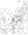
Figure 1 , there is provided a chop saw with a table 12. The saw comprises abase 2 having a rotatable table 4 mounted within it. The rotatable table 4 can pivot about avertical axis 8 within thebase 2. Alocking mechanism 40 can lock the rotatable table 4 in various angular positions within thebase 2. Anextension arm 10 is rigidly attached to the periphery of the rotatable table 4 and extends forward in well known manner within arecess 6 formed within thebase 2. Therecess 6 provides a space in which thearm 10 can move when the rotatable table 4 is rotated about theaxis 8. The top surface of thebase 2, rotatable table 6 andextension arm 10 are flush to provide an overall work surface for a work piece. Aslot 26 extends across the rotatable table 104 and along theextension arm 10. The rotation of the rotatable table 4 about theaxis 8, in conjunction with afence 14 fixed to thebase 2 and which extends across the rotatable table 4, enables the saw to perform mitre cuts. - Connected to the rear of the rotatable table 4 is a
bevel mount 16 which is able to pivot about ahorizontal axis 18 in relation to the rotatable table 4, whichhorizontal axis 18 is parallel to the plane of the work surface of the rotatable table 4. A locking mechanism (not shown) enables the angular position about theaxis 18 of thebevel mount 16 to be releasably locked relative to the rotatable table 4. The pivotal movement of thebevel mount 16 aboutaxis 18 in relation to the rotatable table 4 enables the saw to perform bevel cuts. - Pivotally mounted on the
bevel mount 16 is amotor unit 20, which comprises a motor (not shown) for rotationally driving acircular saw blade 22 mounted on a drive spindle on themotor unit 20 about anaxis 28. Themotor unit 20 can pivot on thebevel mount 16 about anaxis 24 from a raised first position where the motor unit is remote from thebase 2 and rotatable table 4, to a lowered second position where it is in close proximity to thebase 2 and rotatable table. Theaxis 24 is parallel to theaxis 28. Theslot 26 in the table 4 andarm 10 provides a space within the table 4 andarm 10 into which the cutting edge of thesaw blade 22 can pass when themotor unit 20 is pivoted to its lowered position to enable it to pass through a work piece when positioned on the table 4 andarm 10. Themotor unit 20 is biased to an upward position by aspring 100. A locking mechanism is mounted on the bevel mount which is capable of locking themotor unit 20 in its lowered second position as shown inFigure 1 . The locking mechanism comprises apin 160 mounted within thebevel mount 16 in an axailly slideable manner as seen inFigure 8 . Thepin 16 can be slid between a first position where it is disengaged from themotor unit 20, allowing it to freely pivot aboutaxis 24, to a second position when themotor unit 20 is in its lowered second position where itsend 162 engages with agroove 164 formed in the side of themotor unit 20 to lock it in its lower position. The end of the pin is tapered in a lengthwise direction to form a frusto conical shape. Thegroove 164 narrows along its length in order to provide a corresponding tapered shape along its length which can mate with that of theend 162 of thepin 160. By tapering thegroove 164 and theend 162 of thepin 160, it ensures that a tight fit is provided between the two when the end of the pin is engaged with thegroove 164. The pivotal movement of themotor unit 20 in relation to thebevel mount 16 aboutaxis 24 enables the saw to perform chop cuts. - Mounted on the top of the saw is the table 12 which enables the saw to be also used as a table saw. The table 12 is attached to the top side of the
motor unit 20. Aslot 42 is formed through the table through which the top section of thecircular saw blade 22 projects. When themotor unit 20 is locked in its lowered second position, the table 12 is horizontal. A work piece such as a piece of wood can then be slid across the top of the table 12 to engage with the top section of thesaw blade 22 thus enabling the saw to be used as a saw table. Atable fence 44 is releaseably attached to the table 12 and which can be used to guide a work piece across the table 12. Atable guard 46 is releasably mounted on the table which can surround the top of thesaw blade 22 which projects through the table 12 when it is not being used as a table saw. A rivingknife 91 is attached to themotor unit 20 and which projects through theslot 42. - The saw comprises a plurality of guards located below the table 12 which are capable of enclosing the cutting edge of the lower section of the
saw blade 22 for safety purposes when the saw is in its raised first position when it is not being used to perform chop, mitre, or bevel cuts, or when the saw is being used as a table saw, with themotor unit 20 locked in its lowered second position. - A
handle 48 is attached to the motor unit by which a user can grip and pivot themotor unit 20 and thecircular saw blade 22 downwards towards the rotatable table 4. Anelectric switch 50 is mounted adjacent thehandle 48 for activating the motor. The switch can operate in two modes of operation. The first mode is when the saw is performing chop, mitre or bevel cuts. In this mode, theswitch 50 must be constantly depressed by the operator to keep the motor activated thus ensuring the hand of the operator remains on the handle in contact with the switch. In the second mode, when the saw is being used as a table saw, theswitch 50 can be depressed once to activate the motor, the motor remaining activated until the switch is depressed again. This allows the operator to move his hands freely without having to maintain contact with the switch. - The height of the table 12, and hence the amount of
saw blade 22 passing through it, can be adjusted vertically. The height adjustment mechanism for the table 12 is the same as that described inEP1813400 . - The cutting edge of the lower part of the
circular saw blade 22 below the table 12 is surrounded by a guard assembly. The guard assembly comprises a first fixedguard 30 which surrounds the cutting edges of the middle section of thesaw blade 22, a forward guard assembly which is capable of surrounding the lower front section of the cutting edge of thecutting blade 22 and a rear guard assembly which is capable of surrounding the lower rear section of the cutting edge of thecutting blade 22. - The first fixed
guard 30 is attached to themotor unit 20 and surrounds the cutting edges of the middle section of thecircular saw blade 22. The fixedguard 30 remains stationary relative to themotor unit 20. - The forward guard assembly will now be described with reference to
figure 4 . - Pivotally attached to the first fixed
guard 30 is a second forwardpivotal guard 32. The second forwardpivotal guard 32 pivots about theaxis 28 of thecircular saw blade 22. The second pivotal forwardpivotal guard 32 can freely pivot into and out of in a telescopic manner the fixedguard 30. The second forwardpivotal guard 32 is prevented from completely pivoting out of the fixedguard 30 by acatch 52 formed on the second forwardpivotal guard 32 which engages with aledge 54 formed on the fixedguard 30 when the second forwardpivotal guard 32 has pivoted to its furthest position outside of the fixedguard 30. - Pivotally attached to the first fixed
guard 30 is a third forwardpivotal guard 34. The third forwardpivotal guard 32 also pivots about theaxis 28 of thecircular saw blade 22. - The third pivotal forward
pivotal guard 34 can pivot into and out of, in a telescopic manner, the second forwardpivotal guard 32 and also into and out of the fixedguard 30 when the first forwardpivotal guard 32 has moved telescopically inside of the fixedguard 30. The third forwardpivotal guard 34 is prevented from completely pivoting out of the second forwardpivotal guard 32 by asecond catch 56 formed on the third forwardpivotal guard 32 which engages with asecond ledge 58 formed on the first forwardpivotal guard 32 when the second forward guard has pivoted to its furthest position outside of the first forwardpivotal guard 32. The third forwardpivotal guard 34 is prevented from completely pivoting through the second forwardpivotal guard 32 by thesecond catch 56 formed on the third forwardpivotal guard 32 engaging with athird ledge 60 formed on the first forwardpivotal guard 32 when the second forward guard has pivoted to its furthest position inside of the first forwardpivotal guard 32. - A spring (not shown) biases the third forward
pivotal guard 34 downward (clockwise) as shown infigures 1 to 4 . - A
bar 62 is pivotally attached at one end aboutaxis 61 to thebevel mount 16. Anelongate slot 64 is formed along a section of the length of thebar 62 at the other end. Apin 66, rigidly attached to the third forwardpivotal guard 34 passes through theslot 64 and which is capable of sliding along theslot 64. The biasing spring acting on the third forwardpivotal guard 34 causes the guard to pivot until thepin 66 is at theinner end position 65 of theslot 64 where it remains held by the force of the spring. Thepin 66 located within theslot 64 of thebar 62 controls the pivotal movement of thethird guard 34 on the motor unit as themotor unit 20 pivots upwards and downwards. When themotor unit 20 is in its upper most raised first pivotal position, the second and third forwardpivotal guards circular saw blade 22 as shown inFigure 2 . As themotor unit 20 is pivoted downwardly, thebar 62 pushes thepin 66, causing the third forwardpivotal guard 34 to telescopically pivot into the second forwardpivotal guard 32 until thesecond catch 56 engages with thethird ledge 60. As themotor unit 20 continues to be pivoted downwardly, thebar 62 continues to push thepin 66, causing the third forwardpivotal guard 34 together with the second forward pivotal guard via thesecond catch 56 andthird ledge 60, to telescopically pivot into the first fixedguard 30. Theslot 64 allows the guard to pivot freely relative to thebar 62, against the biasing force of the spring, if it encounters a work piece located on thebase 2 or table 4. - The rear guard assembly will now be described with reference to
figure 4 . - The rear guard assembly comprises two parts, a fourth rearward fixed
guard 68 and a fifth rearwardpivotal guard 70. - The fourth rearward fixed
guard 68 comprises a U shaped bracket rigidly fixed to thebevel mount 16 viabolts 72 and which surrounds part of the cutting edge of the rear lower section of theblade 22. Oneside 74 of the U shaped bracket locates along one side of thecutting blade 22, theother side 76 of the U shaped bracket locates along the other side of thecutting blade 22. The fourth rearward fixedguard 68 surrounds the part of the cutting edge of the rear lower section of theblade 22 when themotor unit 20 is in its raised position or its lowered position and all the positions in between, when themotor unit 20 is pivoted aboutaxis 24. A series ofelongate holes 78 are formed in oneside 74 of the fixedguard 68 to enable a user to view the side of theblade 22 located within the fixedguard 68. The fourth rearward fixedguard 68 is located above thefence 14. - The fifth rearward
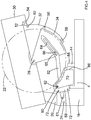
pivotal guard 68 also comprises a U shaped bracket pivotally mounted within the fourth rearward fixedguard 68 via abolt 80. A portion of the fifth rearwardpivotal guard 70 locates behind thefence 14. The fifth rearwardpivotal guard 70 surrounds a part of the cutting edge of the rear lower section of theblade 22 when themotor unit 20 is pivoted aboutaxis 24 to its lowered position. When themotor unit 20 is in its lowest position, oneside 82 of the U shaped bracket locates along one side of thecutting blade 22, theother side 84 of the U shaped bracket locates along the other side of thecutting blade 22. The fifth rearwardpivotal guard 70 can pivot aboutaxis 90 from a first forward position where thefront edges 86 of the bracket are in close proximity to the workingsurface 88 of the fence, adjacent to the slot formed through thefence 14 through which theblade 22 passes when the motor unit is pivoted aboutaxis 24 to its lowered position, to a second rearward position (clockwise as shown inFigure 4 ) where the fifth rearwardpivotal guard 70 is located further inside of the fourth rearward fixed guard and where thefront edges 86 are located a short distance behind thefence 14. Aspring 92 biases the fifth rearwardpivotal guard 70 to its first position. - The rear guard assembly ensures that the part of the cutting edge of the
blade 22 which is located below the fixed guard and behind thefence 14 remains enclosed at all times regardless of the pivotal position of themotor unit 20 relative to thebevel mount 16. When themotor unit 20 is pivoted relative to thebevel mount 16 aboutaxis 24, the fifth rearwardpivotal guard 70 remains in a fixed position relative to the fourth rearward fixedguard 68 andbevel mount 16, the pivotal movement of themotor unit 20 aboutaxis 24 having no effect on the pivotal position of the fifth rearwardpivotal guard 70. When themotor unit 20 is in its raised position as shown inFigure 2 , the whole of the cutting edge of thecutting blade 22 located below the fixedguard 30 is surrounded by the front and rear guard assemblies. When themotor unit 20 is in its lowered position as shown inFigure 1 , the whole of the cutting edge of thecutting blade 22 located below the fixedguard 30 is enclosed by being surrounded in part by the front guard assembly and the rear guard assembly with the remaining portion being located within theslot 26 in the table 4 and arm. - The reason for making part of the rear guard assembly pivotal is due to the movement of the
bevel mount 16, upon which it is mounted, relative to the base. When the saw performs mitre and/or bevel cuts by pivotal movement of the table 4 aboutaxis 8 and/or pivotal movement of the bevel mount aboutaxis 18, the position of thefront edges 86 of the fifth rearwardpivotal guard 70 move relative to theedges 102 of the slot formed through thefence 14 through which theblade 22 can pass as themotor unit 20 moves to its lower position, as shown inFigures 5 to 7 . This can result, in certain positions, in the edges engaging with theedge 102 of thefence 14 and hence block or hinder the movement of thebevel mount 16 in relation to thebase 2. Therefore, by making the part of the rear guard assembly located behind thefence 14 pivotal, the pivotal part can be moved rearwardly slightly by pivotal movement of the fifth rearwardpivotal guard 70 to the movement of thebevel mount 16 being hindered or blocked relative to thebase 2 whilst still enclosing the blade within the rearguard assembly when the rear guard assembly is moved due to the movement of the bevel mount relative to thebase 2 andfence 14. The pivotal movement of the fifth rearwardpivotal guard 70 occurs when it engages with thefence 14 as thebevel mount 16 moves. - An embodiment of a saw according to the present invention will now be described with reference to
Figures 10 to 16 . Where the same features are present in the embodiment, which are present in the example described above, the same reference numbers have been used. The embodiment is the same as the example except for the height adjustment mechanism for the table and the addition of a light guide system. - The height adjustment mechanism for the table 12 will now be described with reference to
Figures 10 to 12 . - The table 12 is moveably mounted on the
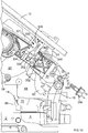
motor unit 20 using atubular support 301. Thetubular support 301 allows the table 12 to slide up and down on themotor unit 20. Thetubular support 301 is rigidly attached to the table and extends in a direction perpendicular to the plane of the working surface of the table 12. The sliding movement of the table 12 is perpendicular to working surface of the table, the sliding movement being vertical with the working surface is horizontal when themotor unit 20 is locked in its lowered second position. - The
tubular support 301 comprises ametal tube 300 having a generally rectangular cross section, the precise shape of which is best seen inFigure 11 . Aninner wall 310 is formed inside of thetube 300 which traverses the width of thetube 300 to form twoelongate passageways tube 300. Formed externally in a wall of thetube 300 on one side is atrough 304 which runs the length of thetube 300. A firstelongate slot 306 is formed in a lengthwise direction in the base of thetrough 304. A secondelongate slot 308 having the same dimensions as the first is formed in the opposite wall of thetube 300 in a matching aligned position. - The
tubular support 301 attaches to aside wall 314 of themotor unit 20 using abolt 316. - Formed on the
side wall 314 of the motor unit is aridge 318 of similar dimensions to those of thetrough 304 on thetubular support 301. When thetubular support 301 is mounted on thewall 314, theridge 318 locates within thetrough 304 as best seen inFigure 11 . Formed through theridge 318 is acircular hole 326 through which theshaft 324 of thebolt 316 passes. Thehead 320 of thebolt 316 locates against aninner surface 322 of thewall 314, the diameter of theshaft 324 of thebolt 316 being slightly smaller than that of thehole 326 to enable theshaft 324 to pass through it with minimal sideways movement, the diameter of thehead 320 being larger than that of thehole 326 to prevent it passing through thehole 326. - The
shaft 324 of thebolt 316 extends through thehole 326, then through the firstelongate slot 306 and then through the secondelongate slot 308. A locking knob assembly 328 (described below) is screwed onto the end of theshaft 324 to sandwich thetubular support 301 against thewall 314 of themotor unit 20. - The locking
knob assembly 328 comprises a self-locking nut 330 (with nylon insert) being screwed onto theshaft 324 of thebolt 316. Thenut 330 is screwed onto theshaft 324 sandwiching awasher 332 between thenut 330 and the outer wall of thetubular support 301. Thenut 330 is screwed onto to the shaft to a predetermine position where a small predetermined compression force is applied to thetubular support 301 against thewall 314 of the motor unit. This allows thetubular support 301 limited movement in a direction away from or towards thewall 314 of the motor unit (Arrow M). A cup shapedwasher 334 surrounds, but does not engage with thenut 330 which abuts against thewasher 332. Aknob 336 is then screwed onto theshaft 324 to sandwich the cup shapedwasher 334 against thewasher 332. Tightening of theknob 336 results in theknob 336 pushing thetubular support 301 against thewall 314 of themotor unit 20, via the cup shapedwasher 334 to fix its position due to friction. The force applied by the knob is dependent on the amount by which the operator screws theknob 336 onto theshaft 324. The slackening of theknob 336 releases thetubular support 301 by allowing the cup shapedwasher 334 to move away from the tubular support. The limited movement of thetubular support 301 in a direction away from or towards thewall 314 of the motor unit (Arrow M) allowed by theself locking nut 330 allows thetubular support 301 to slide in a direction (Arrow N) parallel to its longitudinal axis, relative to themotor unit 20, theshaft 324 of thebolt 316 travelling along the lengths of the twoelongate slots tubular support 301 is controlled by theridge 318 sliding within thetrough 304, theridge 318 being prevented from leaving thetrough 304 by theself locking nut 330. However, the self-lockingnut 330 prevents excessive movement of thetubular support 301 in a direction away from or towards thewall 314 of the motor unit (Arrow M) whilst thetubular support 301 is slid in the direction of Arrow N. - Sideways (Arrow P) movement of the
tubular support 301 is prevented by theridge 318 located in thetrough 304. However, due to tolerances during manufacture, it has been found that limited sideways (Arrow P) movement of thetubular support 301 occurs, allowing either a limited linear movement or a twisting movement relative to themotor unit 20. The twisting movement allows thetubular support 301 to be clamped to theside wall 314 of themotor unit 20 in a limited range of angular positions. This results in the working surface of the table 12 being non horizontal when thetubular support 301 is clamped in a non vertical position, when themotor unit 20 is located in its lowered second position. - In order to overcome this problem, there is provided a sliding
support 340 which is mounted on theside wall 314 of themotor unit 320 and which engages with the side of thetubular support 301. - The sliding
support 340 comprises abody 342 having twooval holes 354 formed through it. Ashaft 346 of afirst bolt 348 passes through one of theholes 354 and screws into a threadedbore 350 formed in theside wall 314 of themotor unit 20. A shaft of asecond bolt 352 passes through the other hole and screws into a second threaded bore formed in the side wall of themotor unit 20. The dimension of the shafts of the twobolts holes 354, allowing thebody 340 to be moved sideways (Arrow P) relative to position of theshafts 346. The dimensions of the head of thebolts holes 354, thus preventing the heads from passing through theholes 354. When thebolts bolts body 342 against thesidewall 314 of themotor unit 20, preventing movement of thebody 342 relative to thewall 314. However, when thebolts bolts body 342, allowing thebody 342 to slide sideways (Arrow P), the shafts of thebolts holes 354 as it does so. - Formed along one side of the
body 342, facing towards thetubular support 301, are twoprojections projections tubular support 301. When thetubular support 301 has been mounted on themotor unit 20 with theridge 318 located within thetrough 304 using theself locking nut 330, thewasher 332 andbolt 316, during manufacture, the slidingsupport 340 is mounted onto thesidewall 314 of themotor unit 20 using the twobolts bolts bores 350 allowing sideways movement of thebody 342 on thewall 314. Thebody 342 is slid towards thetubular support 301 until the twoprojections tubular support 301 and push asidewall 364 of theridge 318 into engagement with a side wall 366 of thetrough 304. A predetermined amount of pressure is exerted by thesiding support 340 in the direction of Arrow P on thetubular support 301 and hence the side wall 366 of thetrough 304 on theridge 318 to ensure that sideways (Arrow P) movement of thetubular support 301 is prevented whilst allowing it to slide vertically (Arrow N) when the height of the table 12 needs to be adjusted. The twobolts bores 350, causing the slidingsupport 340 to be clamped firmly to thewall 314 of themotor unit 20 and thus preventing any sliding movement. The use of twoprojections support 340 and thetubular support 301, thus providing a firm and stable interaction between the two whilst preventing any relative movement between the two when they are engaged, The two projections hold thetrough 304 of thetubular support 301 against the ridge in a firm manner, thus maintaining it in a vertical position. - The light guide system will now be described with reference to
Figures 9 and13 to 16 . The light guide system is used when the saw is being used for chop, mitre or bevel cuts with the work piece being located on thebase 2, rotatable table 4 andarm 10. - Rigidly attached to the under side of the table is a tubular sixth slideable guard 380 (as bet seen in
Figure 15 ). The sixthslideable guard 380 is rectangular in cross section but of smaller dimensions that that of the fixedguard 30. The sixthslideable guard 380 locates inside of the fixed guard and slides in and out of the fixedguard 30 in a telescopic manner as the height of the table 12 above themotor unit 20 is adjusted. The sixthslideable guard 380 ensures that the portion of theblade 22 located between the table 12 and the fixedguard 30 remains enclosed at all times regardless of the height of the table 12 above themotor unit 20. - Located on the underside of the table 12 inside the sixth
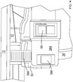
slideable guard 380 adjacent the front end of the sixthslideable guard 380 is alight source 382 comprising a white LED. Thelight source 382 is located directly above the edge of thecutting blade 22 and can shine a beam oflight 396 towards the edge of thecutting blade 22. - An
electronics housing 384 is mounted on themotor unit 20 adjacent thehandle 48. Inside thehousing 384 are the control electronics for the motor and the power supply for thelight source 382. Mounted on the front of thehousing 384 is an electric ON/OFF switch 50 for switching the motor on or off, the motor being power by the control electronics. Mounted adjacent the ON/OFF switch 50 is alight switch 386 which is used by the operator to switch thelight source 382 on or off. The power supply for thelight source 382 and the control electronics is supplied from a 240v AC power supplied via acable 388 and plug 390. - Connected between the
housing 384 and the underside of the table 12 is a telescopic corrugatedplastic tube 392. Anelectric cable 394 connects between thelight source 382 and the power supply for the light source by passing through the side of thehousing 384, through the corrugatedplastic tube 392, underneath the table 12 whilst enclosed by aplate 394. Sufficientelectric cable 394 is located within the corrugated plastic tube to enable the table to be raised to its highest position relative to themotor unit 20, the corrugatedplastic tube 392 stretching as it does so. - The guide system is used when the saw is being used for chop, mitre or bevel cuts with the work piece being located on the
base 2, rotatable table 4 andarm 10. In order to use it, the operator switches on thelight source 382 using thelight switch 386. Themotor unit 20 is in initially in its raised first position as shown inFigure 9 . The light source emits a diverging beam oflight 396 towards the edge of thecutting blade 22, the beam of light passing on both sides of theblade 22. As the whole of the cutting edge of thecutting blade 22 located below the fixedguard 30 is surrounded by the front and rear guard assemblies when themotor unit 20 is in its raised position, thelight beam 396 encounters the inside wall of theguards guards Figure 9 of the base,fence 14 and rotatable table 4 is illuminated by the light source 782. When themotor unit 20 is pivoted towards its lowered second position, theguards guard 30. When this occurs, the area below fixedguard 30 designated 400 inFigure 9 of thebase 2,fence 14 and rotatable table 4 is illuminated by the light source 782. When the second and third forwardpivotal guards positions light beam 396 inside of the fixedguard 30. - In use, a work piece 406 (see
Figure 16 ) is placed on the rotatable table 4 andbase 2. As themotor unit 20 is pivoted towards thework piece 406 to cut it, thepivotal guards blade 22 and thelight beam 396. Thelight beam 396 shines past both sides of theblade 22 and illuminates the top of thework piece 406 in twoareas blade 22 casts ashadow 412 on thework piece 406 as it is positioned between thelight source 382 and the work piece. Theshadow 412 is indicative of the position where thecutting blade 22 will cut thework piece 406 when it comes into contact with thework piece 406. The operator can adjust thework piece 406 using theshadow 412 to ensure the correct part of thework piece 406 is cut. The twoilluminated areas
Claims (9)
- A saw comprising:a base (2);a first table (4) rotatably mounted about a vertical axis (8) within the base (4);a bevel mount (16) pivotally mounted about a horizontal axis (18) on the edge of the table (4);a motor unit (20) pivotally mounted on the bevel mount to allow the motor unit to pivot from a first raised position towards the table to a second lowered position;a saw blade (22) rotatably mounted on and capable of being rotationally driven by the motor unit (20);a second table (12) mounted on the motor unit (20) having a slot (42) formed through it through which the top section of the circular saw blade (22) is capable of projecting; anda guard assembly attached to the motor unit (20 for surrounding at least part of the cutting edge of the cutting blade (22);wherein the guard assembly comprises a fixed guard;a forward guard assembly comprising at least one pivotal guard (32) which is capable of pivoting between a first position where it surrounds part of the cutting edge of the lower forward portion of the cutting blade (22) below the fixed guard (30) and a second position where it locates at least in part inside of the fixed guard (30);a rear guard assembly (68, 70) mounted below the fixed guard (30);characterised in that there is provided a light source (382) mounted to the underside of the second table (12) above the edge of the cutting blade (22) and which is capable of shining a beam of light (396) towards the edge of the blade (22), the beam of light (396) passing on both sides of the blade (22);the rear guard assembly (68, 70) mounted on the bevel mount (16) below the fixed guard (30) and which surrounds part of the cutting edge of the lower rear portion of the cutting blade (22), wherein at least part of the beam of light (396) can pass on both sides of the blade (22) inside of the rear guard assembly and shine onto the base (2) and first table (4).
- A saw as claimed in claim 1 wherein, when the at least one pivotal guard (32) is located in its second position, the light source (382) is capable of shining a beam of light (396) towards the edge of the blade (22), the beam of light (396) passing on both sides of the blade (22) and shining onto the base (2) and first table (4).
- A saw as claimed in either of claims 1 or 2 wherein, when the at least one pivotal guard (32) is located in its first position, the light source (382) is capable of shining a beam of light (396) towards the edge of the blade (22), the beam of light (396) passing on both sides of the blade (22) and shining onto the inside wall of the at least one pivotal guard (32).
- A saw as claimed in any one of claims 1 to 3 wherein there is provided a guard actuation mechanism (62) which automatically moves the at least one pivotal guard (32) from its first position to its second position when the motor unit (20) pivots from its first raised position towards the first table (4) to its second lowered position.
- A saw as claimed in any one of claims 1 to 4 wherein the forward guard assembly comprises two pivotal guards (32, 34) which are capable of pivoting between a first position where the two guards (32, 34) surround part of the cutting edge of the lower forward portion of the cutting blade (22) below the fixed guard (30) and a second position where one pivotal guard (32) locates at least in part inside of the fixed guard (30) and the second pivotal guard (34) locates at least in part inside the first pivotal guard (32) in a telescopic manner.
- A saw as claimed in any one of claims 1 to 5 wherein the rear guard assembly comprises a pivotal guard (70) pivotally mounted on the bevel mount (16) and capable of pivoting through a range of angular positions relative to the bevel mount (16), the beam of light being able to pass inside of the rear guard assembly (68, 70) and shine onto the base (2) and first table (4) when the pivotal guard (70) is located in any angular position relative to the bevel mount (16).
- A saw as claimed in claim 6 wherein the rear guard assembly comprises a fixed guard (68) rigidly attached to the bevel mount (16) and which surrounds part of the cutting edge of the lower rear portion of the cutting blade (22), the pivotal guard (70) being pivotally attached to the fixed guard (68).
- A saw as claimed in any one of claims 1 to 7 wherein the second table (12) is mounted via a height adjustment mechanism on the motor unit to enable it to be raised or lowered relative to the motor unit (20), and wherein there is provided a table guard (380) which surrounds at least part of the cutting edge of the blade (22) and which is attached to the under side of the second table (12) and which telescopes inside and out of the fixed guard (30) as the second table (12) is raised or lowered, the light source (382) being mounted to the underside of the second table (12) inside of the table guard (380).
- A saw as claimed in any one of claims 1 to 8 wherein there is provided a power supply for the light source (382) being mounted on the motor unit (20), an electric cable passing between the power supply and the light source (382) via a telescopic tube (392) which connects between the motor unit (20) and the second table (12).
Applications Claiming Priority (1)
| Application Number | Priority Date | Filing Date | Title |
|---|---|---|---|
| GB1121188.5A GB2497347A (en) | 2011-12-09 | 2011-12-09 | Chop Saw with top Table Saw |
Publications (2)
| Publication Number | Publication Date |
|---|---|
| EP2602075A1 EP2602075A1 (en) | 2013-06-12 |
| EP2602075B1 true EP2602075B1 (en) | 2017-08-09 |
Family
ID=47144225
Family Applications (1)
| Application Number | Title | Priority Date | Filing Date |
|---|---|---|---|
| EP12187620.5A Active EP2602075B1 (en) | 2011-12-09 | 2012-10-08 | Chop saw with top table |
Country Status (2)
| Country | Link |
|---|---|
| EP (1) | EP2602075B1 (en) |
| GB (1) | GB2497347A (en) |
Families Citing this family (4)
| Publication number | Priority date | Publication date | Assignee | Title |
|---|---|---|---|---|
| US10478906B2 (en) * | 2016-09-20 | 2019-11-19 | Zhengyang Industry & Investment Co., Ltd. | Duplex saw |
| CN207189852U (en) | 2017-06-05 | 2018-04-06 | 米沃奇电动工具公司 | Bench saw |
| EP3498444B1 (en) | 2017-12-13 | 2021-03-03 | Scheppach Fabrikation von Holzbearbeitungsmaschinen GmbH | Saw |
| CN109551567B (en) * | 2018-11-28 | 2021-05-14 | 新昌县道宠聚宠物用品有限公司 | Table type sawing machine convenient for processing small logs |
Family Cites Families (12)
| Publication number | Priority date | Publication date | Assignee | Title |
|---|---|---|---|---|
| US2488947A (en) * | 1945-05-28 | 1949-11-22 | American Floor Surfacing Mach | Rotary power handsaw |
| US4257297A (en) * | 1979-01-31 | 1981-03-24 | Peter Nidbella | Circular saw with visual cut line indicator |
| EP0630314A4 (en) * | 1992-03-13 | 1996-07-10 | Lance H Waite | Cut line indicator for power cutting equipment. |
| US7096587B2 (en) * | 2001-09-07 | 2006-08-29 | Hitachi Koki Co., Ltd. | Portable circular power saw with optical alignment |
| US20030233921A1 (en) * | 2002-06-19 | 2003-12-25 | Garcia Jaime E. | Cutter with optical alignment system |
| TWM265200U (en) * | 2004-05-18 | 2005-05-21 | Rexon Ind Corp Ltd | Cutting aligner for circular sawing machine |
| JP2006068903A (en) * | 2004-08-31 | 2006-03-16 | Hitachi Koki Co Ltd | Bench cutter |
| CA2542570A1 (en) * | 2005-04-13 | 2006-10-13 | Black & Decker Inc. | Chop saw |
| AU2007200238B9 (en) * | 2006-01-31 | 2012-06-14 | Black & Decker Inc | Saw |
| US8272303B2 (en) * | 2009-04-28 | 2012-09-25 | Robert Bosch Gmbh | Miter saw with cutting alignment device on a dust chute |
| US8220372B2 (en) * | 2009-04-28 | 2012-07-17 | Credo Technology Corporation | Combination table-miter saw safety system |
| US10265787B2 (en) * | 2010-04-28 | 2019-04-23 | Robert Bosch Tool Corporation | Laser alignment system for saw |
-
2011
- 2011-12-09 GB GB1121188.5A patent/GB2497347A/en not_active Withdrawn
-
2012
- 2012-10-08 EP EP12187620.5A patent/EP2602075B1/en active Active
Non-Patent Citations (1)
| Title |
|---|
| None * |
Also Published As
| Publication number | Publication date |
|---|---|
| GB2497347A (en) | 2013-06-12 |
| GB201121188D0 (en) | 2012-10-31 |
| EP2602075A1 (en) | 2013-06-12 |
Similar Documents
| Publication | Publication Date | Title |
|---|---|---|
| EP1946871B1 (en) | Mitre saw with top table | |
| US5040444A (en) | Saw blade position setting apparatus | |
| US8424434B2 (en) | Universal fence for a power table saw | |
| US20080022825A1 (en) | Miter Saw With Top Table | |
| CN101528429B (en) | A modular guard systems for a power saw | |
| EP2602075B1 (en) | Chop saw with top table | |
| EP1772222B1 (en) | Sliding compound miter saw with locking mechanism | |
| US4367668A (en) | Circular saw attachment | |
| US20120255414A1 (en) | Modular Laser Alignment Device for Power Tool | |
| US20060053993A1 (en) | Circular saw bench | |
| EP2591898B1 (en) | Chop saw with top table | |
| GB2397797A (en) | Hand tool machine | |
| EP2602076B1 (en) | Chop saw with top table | |
| EP3792023A2 (en) | Saw | |
| GB2411619A (en) | Planer and thicknesser | |
| EP1844887B1 (en) | Table fence for a mitre saw with top table | |
| US5540130A (en) | Saw machine | |
| CN100503111C (en) | Table fence and saw for a mitre saw with top table | |
| US7930959B1 (en) | Table saw accessory | |
| EP2591899A1 (en) | Chop saw with top table | |
| AU2012202367B2 (en) | Saw | |
| CA2407368A1 (en) | Guide for work bench | |
| MXPA98003698A (en) | Table for sie |
Legal Events
| Date | Code | Title | Description |
|---|---|---|---|
| PUAI | Public reference made under article 153(3) epc to a published international application that has entered the european phase |
Free format text: ORIGINAL CODE: 0009012 |
|
| AK | Designated contracting states |
Kind code of ref document: A1 Designated state(s): AL AT BE BG CH CY CZ DE DK EE ES FI FR GB GR HR HU IE IS IT LI LT LU LV MC MK MT NL NO PL PT RO RS SE SI SK SM TR |
|
| AX | Request for extension of the european patent |
Extension state: BA ME |
|
| 17P | Request for examination filed |
Effective date: 20131108 |
|
| RBV | Designated contracting states (corrected) |
Designated state(s): AL AT BE BG CH CY CZ DE DK EE ES FI FR GB GR HR HU IE IS IT LI LT LU LV MC MK MT NL NO PL PT RO RS SE SI SK SM TR |
|
| GRAP | Despatch of communication of intention to grant a patent |
Free format text: ORIGINAL CODE: EPIDOSNIGR1 |
|
| INTG | Intention to grant announced |
Effective date: 20170523 |
|
| GRAS | Grant fee paid |
Free format text: ORIGINAL CODE: EPIDOSNIGR3 |
|
| GRAA | (expected) grant |
Free format text: ORIGINAL CODE: 0009210 |
|
| AK | Designated contracting states |
Kind code of ref document: B1 Designated state(s): AL AT BE BG CH CY CZ DE DK EE ES FI FR GB GR HR HU IE IS IT LI LT LU LV MC MK MT NL NO PL PT RO RS SE SI SK SM TR |
|
| REG | Reference to a national code |
Ref country code: GB Ref legal event code: FG4D |
|
| REG | Reference to a national code |
Ref country code: CH Ref legal event code: EP Ref country code: AT Ref legal event code: REF Ref document number: 916325 Country of ref document: AT Kind code of ref document: T Effective date: 20170815 |
|
| REG | Reference to a national code |
Ref country code: IE Ref legal event code: FG4D |
|
| REG | Reference to a national code |
Ref country code: DE Ref legal event code: R096 Ref document number: 602012035571 Country of ref document: DE |
|
| REG | Reference to a national code |
Ref country code: SE Ref legal event code: TRGR |
|
| REG | Reference to a national code |
Ref country code: NL Ref legal event code: MP Effective date: 20170809 |
|
| REG | Reference to a national code |
Ref country code: LT Ref legal event code: MG4D |
|
| REG | Reference to a national code |
Ref country code: AT Ref legal event code: MK05 Ref document number: 916325 Country of ref document: AT Kind code of ref document: T Effective date: 20170809 |
|
| PG25 | Lapsed in a contracting state [announced via postgrant information from national office to epo] |
Ref country code: AT Free format text: LAPSE BECAUSE OF FAILURE TO SUBMIT A TRANSLATION OF THE DESCRIPTION OR TO PAY THE FEE WITHIN THE PRESCRIBED TIME-LIMIT Effective date: 20170809 Ref country code: NO Free format text: LAPSE BECAUSE OF FAILURE TO SUBMIT A TRANSLATION OF THE DESCRIPTION OR TO PAY THE FEE WITHIN THE PRESCRIBED TIME-LIMIT Effective date: 20171109 Ref country code: LT Free format text: LAPSE BECAUSE OF FAILURE TO SUBMIT A TRANSLATION OF THE DESCRIPTION OR TO PAY THE FEE WITHIN THE PRESCRIBED TIME-LIMIT Effective date: 20170809 Ref country code: HR Free format text: LAPSE BECAUSE OF FAILURE TO SUBMIT A TRANSLATION OF THE DESCRIPTION OR TO PAY THE FEE WITHIN THE PRESCRIBED TIME-LIMIT Effective date: 20170809 Ref country code: NL Free format text: LAPSE BECAUSE OF FAILURE TO SUBMIT A TRANSLATION OF THE DESCRIPTION OR TO PAY THE FEE WITHIN THE PRESCRIBED TIME-LIMIT Effective date: 20170809 Ref country code: FI Free format text: LAPSE BECAUSE OF FAILURE TO SUBMIT A TRANSLATION OF THE DESCRIPTION OR TO PAY THE FEE WITHIN THE PRESCRIBED TIME-LIMIT Effective date: 20170809 |
|
| PG25 | Lapsed in a contracting state [announced via postgrant information from national office to epo] |
Ref country code: ES Free format text: LAPSE BECAUSE OF FAILURE TO SUBMIT A TRANSLATION OF THE DESCRIPTION OR TO PAY THE FEE WITHIN THE PRESCRIBED TIME-LIMIT Effective date: 20170809 Ref country code: LV Free format text: LAPSE BECAUSE OF FAILURE TO SUBMIT A TRANSLATION OF THE DESCRIPTION OR TO PAY THE FEE WITHIN THE PRESCRIBED TIME-LIMIT Effective date: 20170809 Ref country code: GR Free format text: LAPSE BECAUSE OF FAILURE TO SUBMIT A TRANSLATION OF THE DESCRIPTION OR TO PAY THE FEE WITHIN THE PRESCRIBED TIME-LIMIT Effective date: 20171110 Ref country code: PL Free format text: LAPSE BECAUSE OF FAILURE TO SUBMIT A TRANSLATION OF THE DESCRIPTION OR TO PAY THE FEE WITHIN THE PRESCRIBED TIME-LIMIT Effective date: 20170809 Ref country code: RS Free format text: LAPSE BECAUSE OF FAILURE TO SUBMIT A TRANSLATION OF THE DESCRIPTION OR TO PAY THE FEE WITHIN THE PRESCRIBED TIME-LIMIT Effective date: 20170809 Ref country code: IS Free format text: LAPSE BECAUSE OF FAILURE TO SUBMIT A TRANSLATION OF THE DESCRIPTION OR TO PAY THE FEE WITHIN THE PRESCRIBED TIME-LIMIT Effective date: 20171209 Ref country code: BG Free format text: LAPSE BECAUSE OF FAILURE TO SUBMIT A TRANSLATION OF THE DESCRIPTION OR TO PAY THE FEE WITHIN THE PRESCRIBED TIME-LIMIT Effective date: 20171109 |
|
| PG25 | Lapsed in a contracting state [announced via postgrant information from national office to epo] |
Ref country code: CZ Free format text: LAPSE BECAUSE OF FAILURE TO SUBMIT A TRANSLATION OF THE DESCRIPTION OR TO PAY THE FEE WITHIN THE PRESCRIBED TIME-LIMIT Effective date: 20170809 Ref country code: DK Free format text: LAPSE BECAUSE OF FAILURE TO SUBMIT A TRANSLATION OF THE DESCRIPTION OR TO PAY THE FEE WITHIN THE PRESCRIBED TIME-LIMIT Effective date: 20170809 Ref country code: RO Free format text: LAPSE BECAUSE OF FAILURE TO SUBMIT A TRANSLATION OF THE DESCRIPTION OR TO PAY THE FEE WITHIN THE PRESCRIBED TIME-LIMIT Effective date: 20170809 |
|
| REG | Reference to a national code |
Ref country code: DE Ref legal event code: R097 Ref document number: 602012035571 Country of ref document: DE |
|
| PG25 | Lapsed in a contracting state [announced via postgrant information from national office to epo] |
Ref country code: MC Free format text: LAPSE BECAUSE OF FAILURE TO SUBMIT A TRANSLATION OF THE DESCRIPTION OR TO PAY THE FEE WITHIN THE PRESCRIBED TIME-LIMIT Effective date: 20170809 Ref country code: EE Free format text: LAPSE BECAUSE OF FAILURE TO SUBMIT A TRANSLATION OF THE DESCRIPTION OR TO PAY THE FEE WITHIN THE PRESCRIBED TIME-LIMIT Effective date: 20170809 Ref country code: SK Free format text: LAPSE BECAUSE OF FAILURE TO SUBMIT A TRANSLATION OF THE DESCRIPTION OR TO PAY THE FEE WITHIN THE PRESCRIBED TIME-LIMIT Effective date: 20170809 Ref country code: SM Free format text: LAPSE BECAUSE OF FAILURE TO SUBMIT A TRANSLATION OF THE DESCRIPTION OR TO PAY THE FEE WITHIN THE PRESCRIBED TIME-LIMIT Effective date: 20170809 |
|
| REG | Reference to a national code |
Ref country code: CH Ref legal event code: PL |
|
| PLBE | No opposition filed within time limit |
Free format text: ORIGINAL CODE: 0009261 |
|
| STAA | Information on the status of an ep patent application or granted ep patent |
Free format text: STATUS: NO OPPOSITION FILED WITHIN TIME LIMIT |
|
| 26N | No opposition filed |
Effective date: 20180511 |
|
| REG | Reference to a national code |
Ref country code: IE Ref legal event code: MM4A |
|
| REG | Reference to a national code |
Ref country code: FR Ref legal event code: ST Effective date: 20180629 |
|
| PG25 | Lapsed in a contracting state [announced via postgrant information from national office to epo] |
Ref country code: CH Free format text: LAPSE BECAUSE OF NON-PAYMENT OF DUE FEES Effective date: 20171031 Ref country code: LU Free format text: LAPSE BECAUSE OF NON-PAYMENT OF DUE FEES Effective date: 20171008 Ref country code: LI Free format text: LAPSE BECAUSE OF NON-PAYMENT OF DUE FEES Effective date: 20171031 |
|
| REG | Reference to a national code |
Ref country code: BE Ref legal event code: MM Effective date: 20171031 |
|
| PG25 | Lapsed in a contracting state [announced via postgrant information from national office to epo] |
Ref country code: FR Free format text: LAPSE BECAUSE OF NON-PAYMENT OF DUE FEES Effective date: 20171031 Ref country code: BE Free format text: LAPSE BECAUSE OF NON-PAYMENT OF DUE FEES Effective date: 20171031 Ref country code: SI Free format text: LAPSE BECAUSE OF FAILURE TO SUBMIT A TRANSLATION OF THE DESCRIPTION OR TO PAY THE FEE WITHIN THE PRESCRIBED TIME-LIMIT Effective date: 20170809 |
|
| PG25 | Lapsed in a contracting state [announced via postgrant information from national office to epo] |
Ref country code: MT Free format text: LAPSE BECAUSE OF NON-PAYMENT OF DUE FEES Effective date: 20171008 |
|
| PG25 | Lapsed in a contracting state [announced via postgrant information from national office to epo] |
Ref country code: IE Free format text: LAPSE BECAUSE OF NON-PAYMENT OF DUE FEES Effective date: 20171008 |
|
| PGFP | Annual fee paid to national office [announced via postgrant information from national office to epo] |
Ref country code: DE Payment date: 20181024 Year of fee payment: 12 |
|
| PG25 | Lapsed in a contracting state [announced via postgrant information from national office to epo] |
Ref country code: HU Free format text: LAPSE BECAUSE OF FAILURE TO SUBMIT A TRANSLATION OF THE DESCRIPTION OR TO PAY THE FEE WITHIN THE PRESCRIBED TIME-LIMIT; INVALID AB INITIO Effective date: 20121008 |
|
| PG25 | Lapsed in a contracting state [announced via postgrant information from national office to epo] |
Ref country code: CY Free format text: LAPSE BECAUSE OF NON-PAYMENT OF DUE FEES Effective date: 20170809 |
|
| PG25 | Lapsed in a contracting state [announced via postgrant information from national office to epo] |
Ref country code: MK Free format text: LAPSE BECAUSE OF FAILURE TO SUBMIT A TRANSLATION OF THE DESCRIPTION OR TO PAY THE FEE WITHIN THE PRESCRIBED TIME-LIMIT Effective date: 20170809 |
|
| PG25 | Lapsed in a contracting state [announced via postgrant information from national office to epo] |
Ref country code: TR Free format text: LAPSE BECAUSE OF FAILURE TO SUBMIT A TRANSLATION OF THE DESCRIPTION OR TO PAY THE FEE WITHIN THE PRESCRIBED TIME-LIMIT Effective date: 20170809 |
|
| PG25 | Lapsed in a contracting state [announced via postgrant information from national office to epo] |
Ref country code: PT Free format text: LAPSE BECAUSE OF FAILURE TO SUBMIT A TRANSLATION OF THE DESCRIPTION OR TO PAY THE FEE WITHIN THE PRESCRIBED TIME-LIMIT Effective date: 20170809 |
|
| PG25 | Lapsed in a contracting state [announced via postgrant information from national office to epo] |
Ref country code: AL Free format text: LAPSE BECAUSE OF FAILURE TO SUBMIT A TRANSLATION OF THE DESCRIPTION OR TO PAY THE FEE WITHIN THE PRESCRIBED TIME-LIMIT Effective date: 20170809 |
|
| PG25 | Lapsed in a contracting state [announced via postgrant information from national office to epo] |
Ref country code: SE Free format text: LAPSE BECAUSE OF NON-PAYMENT OF DUE FEES Effective date: 20191009 |
|
| PG25 | Lapsed in a contracting state [announced via postgrant information from national office to epo] |
Ref country code: IT Free format text: LAPSE BECAUSE OF NON-PAYMENT OF DUE FEES Effective date: 20191008 |
|
| PGFP | Annual fee paid to national office [announced via postgrant information from national office to epo] |
Ref country code: GB Payment date: 20230817 Year of fee payment: 12 |
|
| PGFP | Annual fee paid to national office [announced via postgrant information from national office to epo] |
Ref country code: DE Payment date: 20230822 Year of fee payment: 12 |