EP2602028A1 - Electronic device and system for controlling applications using at least one piezoelectronic, electrostrictive or magnetostrictive transducer - Google Patents
Electronic device and system for controlling applications using at least one piezoelectronic, electrostrictive or magnetostrictive transducer Download PDFInfo
- Publication number
- EP2602028A1 EP2602028A1 EP12306532.8A EP12306532A EP2602028A1 EP 2602028 A1 EP2602028 A1 EP 2602028A1 EP 12306532 A EP12306532 A EP 12306532A EP 2602028 A1 EP2602028 A1 EP 2602028A1
- Authority
- EP
- European Patent Office
- Prior art keywords
- control
- function
- macro
- functions
- elementary
- Prior art date
- Legal status (The legal status is an assumption and is not a legal conclusion. Google has not performed a legal analysis and makes no representation as to the accuracy of the status listed.)
- Granted
Links
- 230000006870 function Effects 0.000 claims abstract description 184
- 238000012545 processing Methods 0.000 claims abstract description 33
- 238000004590 computer program Methods 0.000 claims abstract description 17
- 238000004891 communication Methods 0.000 claims description 10
- 238000010276 construction Methods 0.000 claims description 6
- 101100260702 Mus musculus Tinagl1 gene Proteins 0.000 description 9
- 101150088826 arg1 gene Proteins 0.000 description 9
- 101150026173 ARG2 gene Proteins 0.000 description 8
- 238000004140 cleaning Methods 0.000 description 5
- 239000007788 liquid Substances 0.000 description 5
- 230000006399 behavior Effects 0.000 description 4
- 238000006073 displacement reaction Methods 0.000 description 4
- 238000004519 manufacturing process Methods 0.000 description 4
- 239000000463 material Substances 0.000 description 4
- 238000005520 cutting process Methods 0.000 description 3
- 125000004122 cyclic group Chemical group 0.000 description 3
- 230000035939 shock Effects 0.000 description 3
- 238000003466 welding Methods 0.000 description 3
- 240000008042 Zea mays Species 0.000 description 2
- 239000000443 aerosol Substances 0.000 description 2
- 238000004364 calculation method Methods 0.000 description 2
- 238000006243 chemical reaction Methods 0.000 description 2
- 238000013461 design Methods 0.000 description 2
- 239000006185 dispersion Substances 0.000 description 2
- 238000011068 loading method Methods 0.000 description 2
- 238000005259 measurement Methods 0.000 description 2
- 230000010363 phase shift Effects 0.000 description 2
- 230000000750 progressive effect Effects 0.000 description 2
- 230000001360 synchronised effect Effects 0.000 description 2
- 241000195940 Bryophyta Species 0.000 description 1
- 230000003213 activating effect Effects 0.000 description 1
- 230000006978 adaptation Effects 0.000 description 1
- 244000309464 bull Species 0.000 description 1
- 238000001514 detection method Methods 0.000 description 1
- 238000010586 diagram Methods 0.000 description 1
- 230000000694 effects Effects 0.000 description 1
- 238000011049 filling Methods 0.000 description 1
- 238000001914 filtration Methods 0.000 description 1
- 239000006260 foam Substances 0.000 description 1
- 238000010438 heat treatment Methods 0.000 description 1
- 238000002955 isolation Methods 0.000 description 1
- 238000000034 method Methods 0.000 description 1
- 238000002156 mixing Methods 0.000 description 1
- 239000000203 mixture Substances 0.000 description 1
- 235000011929 mousse Nutrition 0.000 description 1
- 210000000056 organ Anatomy 0.000 description 1
- 239000000843 powder Substances 0.000 description 1
- 230000002441 reversible effect Effects 0.000 description 1
- 239000007921 spray Substances 0.000 description 1
- 230000003068 static effect Effects 0.000 description 1
- 238000004506 ultrasonic cleaning Methods 0.000 description 1
- 238000002604 ultrasonography Methods 0.000 description 1
Images


Classifications
-
- G—PHYSICS
- G05—CONTROLLING; REGULATING
- G05B—CONTROL OR REGULATING SYSTEMS IN GENERAL; FUNCTIONAL ELEMENTS OF SUCH SYSTEMS; MONITORING OR TESTING ARRANGEMENTS FOR SUCH SYSTEMS OR ELEMENTS
- G05B15/00—Systems controlled by a computer
- G05B15/02—Systems controlled by a computer electric
-
- B—PERFORMING OPERATIONS; TRANSPORTING
- B06—GENERATING OR TRANSMITTING MECHANICAL VIBRATIONS IN GENERAL
- B06B—METHODS OR APPARATUS FOR GENERATING OR TRANSMITTING MECHANICAL VIBRATIONS OF INFRASONIC, SONIC, OR ULTRASONIC FREQUENCY, e.g. FOR PERFORMING MECHANICAL WORK IN GENERAL
- B06B1/00—Methods or apparatus for generating mechanical vibrations of infrasonic, sonic, or ultrasonic frequency
- B06B1/02—Methods or apparatus for generating mechanical vibrations of infrasonic, sonic, or ultrasonic frequency making use of electrical energy
- B06B1/0207—Driving circuits
Definitions
- the present invention relates to the field of control, by means of an electric power generator, of applications using at least one piezoelectric, electrostrictive or magnetostrictive transducer, and in particular, but not exclusively an ultrasonic transducer.
- At least one transducer also called actuator
- piezoelectric piezoelectric, electrostrictive or magnetostrictive
- electrostrictive magnetostrictive
- vibratory mechanical waves and in particular ultrasonic waves
- many industrial fields such as, for example, and in a nonlimiting and non-exhaustive manner, cleaning, cutting, welding, etc ...
- At least one piezoelectric transducer which is powered by an electric power generator, and which transforms the electrical energy supplied by the generator into a mechanical movement.
- the electrical energy supplied by the generator is transformed into a vibratory mechanical movement in a range of frequencies and amplitudes which depend in particular on the application.
- Industrial systems implementing a vibratory mechanical movement controlled by a transducer operate in the ultrasound domain (frequencies typically greater than 20 kHz). But some applications can also implement a transducer operating at frequencies below 20 kHz.
- the electric power generator delivers a power signal, whose frequency and voltage can for example be adapted to the resonant frequency or antiresonance of the transducer operating in its environment.
- this power signal delivered by the generator is adjustable (for example in frequency and / or amplitude).
- this power signal delivered by the generator is controlled from external setpoints and information (eg current and voltage) measured on the transducer.
- control part was performed in an analog manner, which required complex adjustments and made the control devices frozen and difficult to adapt.
- An exemplary control of an ultrasonic transducer with analog servocontrol is described for example in the US patent US 5,406,503 .
- An object of the invention is to propose a new technical solution for controlling, by means of a suitable power generator, applications employing at least one piezoelectric, electrostrictive or magnetostrictive transducer, which solution has the advantage to be universal, i.e. non-specific to a single application, and to be very flexible and easily adaptable to applications in different technical fields and to electrostrictive or magnetostrictive piezoelectric transducers having structures and properties different mechanical
- Another object of the invention is to propose a control solution for a piezoelectric, electrostrictive or magnetostrictive transducer which is easily scalable and which can easily and quickly be configured or modified.
- the invention also relates to an application control system implementing at least one piezoelectric transducer, electrostrictive, or magnetostrictive, said system comprising an electronic device referred to above, and an electronic processing unit, which is connectable to said electronic device.
- Another object of the invention is a computer program comprising computer program code means adapted to be executed by electronic processing means (3), and, when executed by electronic processing means (3), the construction of control macro-functions (M) from a first family (A) of control functions comprising one or more different elementary control functions (An), each of which makes it possible to adjust the amplitude of a control signal to be generated by an electric power generator, a second family (T) of control functions comprising one or more different elementary control functions (Tn), each of which makes it possible to adjust the duration said control signal, and a third family (C) of control functions having a plurality of different elementary control functions (Cn), each of which makes it possible to adjust the cycle of said control signal.
- control macro-functions M
- F fourth family of control functions comprising one or more different elementary control functions (Fn), each of which makes it possible to adjust the frequency of said control signal.
- control macro-function which macro-control function (M) comprises a first elementary control function (An), which makes it possible to adjust, preferably as a function of at least one adjustment value, the amplitude of a control signal to be generated by an electric power generator, of a second elementary control function (Tn), which makes it possible to adjust the duration of said control signal (S), preferably as a function of at least one adjustment value, and a third elementary control function (Cn), which makes it possible to adjust the cycle of the control signal (S), preferably as a function of at least one adjustment value, said program perm it being for a user to define the setting value (s) of the elementary control function (s).
- An first elementary control function
- Tn second elementary control function
- Cn third elementary control function
- said parameterization computer program allows the parameterization of a control macro-function (M) also comprising a fourth elementary control function (Fn), which makes it possible to adjust the frequency of said control signal, preferably according to at least one setting value.
- M control macro-function
- Fn fourth elementary control function
- the invention also relates to a support that can be read by a computer and on which is recorded a computer program referred to above.
- FIG. 1 a particular example of an electronic architecture of an electronic device 1 which is in accordance with the invention, and which makes it possible to control a load 2 comprising at least one transducer (or actuator) which, depending on the case, can be of piezoelectric, electrostrictive type, or magnetostrictive.
- piezoelectric or electrostrictive transducer denotes any device that generally makes it possible to transform an electrical energy into a mechanical energy by deformation of a material.
- magnetictostrictive transducer refers to any device that generally makes it possible to transform electromagnetic energy into mechanical energy by deforming a material.
- the charge 2 and the associated piezoelectric, electrostrictive or magnetostrictive transducer (s) depend on the application and can be very varied.
- the electronic device 1 can be adapted and parameterized to control one or the other of the following charges 2, the list of which is given below by way of example only of applications of the invention and in a nonlimiting manner and non-exhaustive of the invention.
- the electronic device 1 is connected to one or more transducers which are fixed on the outer wall of a tank itself filled with a cleaning liquid.
- the "electrical energy supplied by the electronic device 1 is transformed by the transducer (s) into a vibratory energy which induces a cavitation phenomenon in the bath. This cavitation produces the cleaning of submerged parts.
- the electronic device 1 is connected to a transducer, which performs an actuator function, and whose movement is proportional to a voltage delivered by the electronic device 1.
- This movement is for example static displacement if the voltage delivered is continuous; it is for example pulsed if the command delivered is a pulse, or for example of a more general form proportional to the signal produced by the electronic device.
- the purpose of the induced effect is to control the movement of a mechanical device coupled to the actuator (transducer), to produce a very low frequency vibration or to induce a propulsion shock.
- the device can be a bar or a ring.
- the creation of a progressive wave is achieved by superimposing two standing waves with a phase shift of 90 ° in time, and a phase shift of 90 ° in space.
- Two electronic devices 1 are necessary to achieve this end.
- the first device 1 supplies a transducer with a controlled phase
- the second device 1 supplies the second transducer with a phase shifted by 90 ° synchronized to the first electronic device.
- An example of this type of application is described in the article: "A Survey of Ultrasonic Waves in Powder Transportation", E. Murimi, J. Kihiu, G. Nyakoe and S. Mutuli
- the same principle is applicable to realize a rotary piezoelectric electric motor.
- the electronic device 1 comprises an electric power generator 10, which in operation feeds the load 2, with an electrical power signal S, designated in this text by "control signal".
- This electric power generator 10 is automatically controlled by a programmable electronic processing unit 11.
- the electronic architecture of the electric power generator 10 is known per se, and comprises, for example, an H-bridge 101 supplying an adaptation network 102, which comprises for example a transformer, and which delivers the above-mentioned control signal S.
- the bridge in H is ordered by the programmable electronic processing unit 11 in the usual manner by means of a control electronics 103 ("Driver").
- This particular electronic architecture of the electric power generator 10 is not limiting of the invention, and can be replaced by any electronic architecture for delivering a power signal (control signal S) which is adjustable.
- the programmable electronic processing unit 11 comprises a digital processor 110 associated with a RAM RAM 111 and an electrically erasable read only memory 112, of the EEPROM type.
- the digital processor 110 may for example be a microprocessor, a microcontroller or a processor specialized in DSP signal processing.
- the digital processor 110 has an input port 110a which is connected to the matching network 102, so as to detect in real time the current I and the voltage V of the control signal S applied. 2. This detection makes it possible in certain cases to achieve a servo control loop of the control signal S with respect to one or more setpoints by means of the digital processor 110.
- the digital processor 110 also comprises at least one communication port 110b, which may for example be a RS485 slow serial input / output port or an Ethernet port.
- the communication port 110b is used in particular to enable an external electronic processing unit 3, such as for example a PLC or a computer, to communicate with the digital processor 110, for example to enable the external electronic processing unit 3 to control the digital processor 110, or to load or reverse to recover data in ROM 112 or in RAM 111.
- an external electronic processing unit 3 such as for example a PLC or a computer
- the exchange of data with the outside on the port of communication 110b is preferably carried out through a galvanic isolation 13 comprising for example in the usual manner opto-couplers.
- control macro-functions also designated in the text as shorthand by "macros", which are each constituted by elementary control functions, and which make it possible to the automatic adjustment by the processor 110 of the frequency, the amplitude, the duration and the cycle of the control signal S.
- each elementary control function is characterized by one or more adjustment parameters (ArgN), which are more or less complex, which are specific to each elementary function, and which allow the configuration of each elementary control function. a command macro function.
- Adjustments will also be designated in the following text by the terms "arguments".
- each argument (ArgN) of a basic control function of a macro-function M must be filled with one or more values of specific settings of this argument.
- An optimum resonant frequency is determined within the allowed frequency range.
- the slaving is carried out by means of a regulation loop as a function of the estimated phase difference between the voltage V and the current I.
- F ⁇ 2 f Phase ⁇ ends ⁇ Ffinale ⁇ Tn
- Ffinale High limit frequency servo frequency Hz 2 Tn Number of phase measurements used in the calculation of the error (average) 1
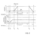
- FIG. figure 2 At the start of the system, the behavior of the frequency and amplitude of the control signal S is illustrated in FIG. figure 2 .
- a frequency variation dF is applied to a center frequency Fc.
- the modulation frequency is determined by Fm.
- F ⁇ 3 f Fc ⁇ dF ⁇ fm
- Argument Description Unit Precision Fc Central frequency assumed optimal Hz 2 dF Frequency excursion Hz 1 fm Modulation frequency Hz 0.01
- the coefficient k is a random coefficient varying from 0 to 1.
- the sign of the function will also be random.
- A2 Amplitude controlled by power
- a power setpoint is imposed by the user.
- the current measurement I and the voltage V on the transducer allow the calculation of the effective power supplied by the generator. This power is compared to the setpoint to maintain the stable setpoint whatever the disturbances to which the transducer can be subjected.
- AT ⁇ 2 f CGSM Argument Description Unit Precision CGSM Power to be controlled [0-100] % 1
- the T1 function has no arguments (setting value).
- the control signal S is generated for an indefinite period, until an external interruption of this signal is received by the generator 10.
- a duration equal to zero means an infinite duration.
- the device 1 will stop only from a setpoint or external command.
- the F1 function has no arguments (setting value).
- this function C1 is used in a macro-function, the control signal S is non-cyclic, that is to say is generated without repetition of a cycle.
- a stopping time is determined by the duty cycle Ton / Ttotal.
- VS ⁇ 2 f RC Argument Description Unit Precision RC Cyclic report (Ton / Ttotal) % 1
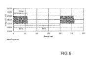
- the behavior of the amplitude of the signal S is illustrated on the figure 5 .
- the user of the device 1 wishes to generate a wave train modulated to a fixed amplitude for a specific duration and repeat this operation regularly.
- the parameters of the macro will be as follows: Settings Values Last name SWEEP Description A frequency variation is allowed according to a frequency deviation parameter (dF) with respect to the optimum center frequency.
- SWEEP F ⁇ 3 Fc ⁇ dF ⁇ fm ⁇ AT ⁇ 1 PscG ⁇ T ⁇ 2 TSCG ⁇ VS ⁇ 2 RC
- SWEEP F ⁇ 3 30000 ⁇ 1000 ⁇ 2 ⁇ AT ⁇ 1 80 ⁇ T ⁇ 2 600 ⁇ VS ⁇ 2 25
- control macro-functions Mn are also designed by the manufacturer of the electronic device 1, and are for example stored on a server in a macro-function database.
- the manufacturer of the electronic device 1 uses a specific computer program for constructing macro-control functions, which is capable of being executed by electronic processing means, such as a microcomputer 3.
- This construction program of macro-control functions allows, when executed, the construction by a user of the program, of control macro-functions (M) from the elementary control functions of the aforementioned families of functions F, A, T, C .
- each Mn control macro-function which has been configured, is stored locally in a backup file, for example on the hard disk of the user's microcomputer, being assigned to a given electronic device 1.
- the backup file contains the basic functions assigned to the macro as well as all the arguments that the user provides.
- the user connects his microcomputer to the communication port 110b of the device 1 and loads the control macro-function or functions that have been configured in the read-only memory 112 of the device 1.
- the arguments ArgN of the Basic functions are not transferred.
- the electronic device 1 can thus contain in the read-only memory 112 one or more configured control macro-functions M1, M2, ... Mn.
- the microcomputer 3 of the user being connected to the communication port 110b, the user displays on the screen of his microcomputer the macro-control function stored in RAM memory 111, activates a single macro-function M among the set of available macro-functions and transfers in the read-only memory 112 of the electronic device 1 the arguments (Arg1, ...) of the elementary functions of the control macro-function which are stored in the backup file on the hard disk of the microcomputer.
- SWEEP F ⁇ 3 28000 ⁇ 1000 ⁇ 0.50 ⁇ AT ⁇ 1 80 ⁇ T ⁇ 1 600 ⁇ VS ⁇ 2 25
- the EEPROM 112 of the device When transferring the macro to the electronics, the EEPROM 112 of the device will have the following information: Number of usable macros 1 Number of the active macro 1 Frequency Amplitude Time Cycle MACRO 1 3 1 1 2 MACRO 2 0 0 0 0 ... 0 0 0 0 MACRO 31 0 0 0 0 0
- the electronic control device 1 can operate autonomously, the processor 110 being programmed to drive the H 101 bridge of the generator 10 from the active control macro M function.
- a programmable controller or equivalent is connected to the communication port 110b of the electronic device 1 and automatically controls the device 1 by automatically activating a control macro-function at a time depending on a program executed by the PLC.
- the macro functions are constructed from the four families (F, A, T, C) of elementary control functions.
- the family Frequency F is not essential, and the Macro functions can be built from the three families (A, T, C).
- the arguments Arg 1 , Arg 2 ,..., Of one or more control functions are not necessarily constants in time, but can also constitute variables that evolve over time. according to a programmed control law, which can in particular take into account the evolution of the system which is controlled by the electronic control device.
- This design in the form of macro-control functions consisting of parametrable basic functions allows the user of the electronic device 1 to easily and rapidly develop and develop a given application, by setting the universal electronic device 1 to adapt it to specific way to the piezoelectric, electrostrictive, or magnetostrictive transducer of the application.
- This new design also allows the manufacturer of the electronic device 1 to easily configure and develop this device 1, by loading in the memory 112, new basic control functions and / or by modifying the existing elementary control functions.
Landscapes
- Engineering & Computer Science (AREA)
- Mechanical Engineering (AREA)
- General Engineering & Computer Science (AREA)
- Physics & Mathematics (AREA)
- General Physics & Mathematics (AREA)
- Automation & Control Theory (AREA)
- Apparatuses For Generation Of Mechanical Vibrations (AREA)
- General Electrical Machinery Utilizing Piezoelectricity, Electrostriction Or Magnetostriction (AREA)
- Dc-Dc Converters (AREA)
Abstract
Description
La présente invention concerne le domaine de la commande, au moyen d'un générateur électrique de puissance, d'applications mettant en oeuvre au moins un transducteur piézoélectrique, électrostrictif ou magnétostrictif, et en particulier, mais pas exclusivement un transducteur ultrasonore.The present invention relates to the field of control, by means of an electric power generator, of applications using at least one piezoelectric, electrostrictive or magnetostrictive transducer, and in particular, but not exclusively an ultrasonic transducer.
Il existe de nombreuses applications industrielles mettant en oeuvre au moins un transducteur (également désigné actionneur) piézoélectrique, électrostrictif ou magnétostrictif, qui permet de commander à l'aide d'un champ électrique ou magnétique un mouvement mécanique, tel qu'une vibration mécanique, un déplacement ou un choc mécanique.There are many industrial applications using at least one transducer (also called actuator) piezoelectric, electrostrictive or magnetostrictive, which allows to control with the aid of an electric or magnetic field a mechanical movement, such as a mechanical vibration, displacement or mechanical shock.
Plus particulièrement, dans le cas particulier de la génération de vibrations mécaniques, les ondes mécaniques vibratoires, et notamment les ondes ultrasonores, sont utilisées dans très nombreux domaines industriels, tels que par exemple, et de manière non limitative et non exhaustive, le nettoyage, la découpe, le soudage, etc...More particularly, in the particular case of the generation of mechanical vibrations, vibratory mechanical waves, and in particular ultrasonic waves, are used in many industrial fields, such as, for example, and in a nonlimiting and non-exhaustive manner, cleaning, cutting, welding, etc ...
Quel que soit le type d'application, on utilise au moins un transducteur piézoélectrique, électrostrictif ou magnétostrictif, qui est alimenté par un générateur électrique de puissance, et qui permet de transformer l'énergie électrique fournie par le générateur en un mouvement mécanique.Whatever the type of application, at least one piezoelectric transducer, electrostrictive or magnetostrictive, which is powered by an electric power generator, and which transforms the electrical energy supplied by the generator into a mechanical movement.
Dans le cas particulier d'un mouvement vibratoire, l'énergie électrique fournie par le générateur est transformée en un mouvement mécanique vibratoire dans une plage de fréquences et d'amplitudes qui dépendent notamment de l'application. De nombreuses applications industrielles mettant en oeuvre un mouvement mécanique vibratoire commandé par un transducteur fonctionnent dans le domaine ultrasonore (fréquences typiquement supérieures à 20kHz). Mais certaines applications peuvent également mettre en oeuvre un transducteur fonctionnant à des fréquences inférieures à 20kHz.In the particular case of a vibratory movement, the electrical energy supplied by the generator is transformed into a vibratory mechanical movement in a range of frequencies and amplitudes which depend in particular on the application. Many applications Industrial systems implementing a vibratory mechanical movement controlled by a transducer operate in the ultrasound domain (frequencies typically greater than 20 kHz). But some applications can also implement a transducer operating at frequencies below 20 kHz.
Plus particulièrement, dans le domaine vibratoire, le générateur électrique de puissance délivre un signal de puissance, dont la fréquence et la tension peuvent par exemple être adaptées à la fréquence de résonance ou d'antirésonance du transducteur en fonctionnement dans son environnement. Le plus souvent ce signal de puissance délivré par le générateur est réglable (par exemple en fréquence et/ou en amplitude). Egalement, dans certaines réalisations connues, ce signal de puissance délivré par le générateur est asservi à partir de consignes extérieures et d'informations (par exemple courant et tension) mesurées sur le transducteur.More particularly, in the vibratory field, the electric power generator delivers a power signal, whose frequency and voltage can for example be adapted to the resonant frequency or antiresonance of the transducer operating in its environment. Most often this power signal delivered by the generator is adjustable (for example in frequency and / or amplitude). Also, in certain known embodiments, this power signal delivered by the generator is controlled from external setpoints and information (eg current and voltage) measured on the transducer.
Pendant de nombreuses années, la partie commande a été réalisée de manière analogique, ce qui imposait des réglages complexes et rendait les dispositifs de commande figés et difficilement adaptables. Un exemple de commande d'un transducteur ultrasonore avec asservissement analogique est décrit par exemple dans le brevet américain
Plus récemment, l'utilisation de solutions à base de commandes numériques a permis d'intégrer des fonctionnalités nouvelles dans le contrôle du fonctionnement du transducteur. Des exemples de commande d'un transducteur ultrasonore avec asservissement numérique sont décrits par exemple dans les publications suivantes : demandes de brevet européen
Il est remarquable de constater que les dispositifs décrits restent assez figés dans leur mode de réalisation et sont le plus souvent spécifiques d'une application donnée, c'est-à-dire d'un type donné de transducteur piézoélectrique, électrostrictif ou magnétostrictif.It is remarkable to note that the devices described remain quite fixed in their embodiment and are most often specific to a given application, that is to say a given type of piezoelectric transducer, electrostrictive or magnetostrictive.
Un objectif de l'invention est de proposer une nouvelle solution technique pour la commande, au moyen d'un générateur électrique de puissance adapté, d'applications mettant en oeuvre au moins un transducteur piézoélectrique, électrostrictif ou magnétostrictif, laquelle solution présente l'avantage d'être universelle, c'est-à-dire non spécifique à une seule application, et d'être très flexible et facilement adaptable à des applications dans des domaines techniques différents et à des transducteurs piézoélectriques électrostrictif ou magnétostrictif ayant des structures et des propriétés mécaniques différentes. Un autre objectif de l'invention est de proposer une solution de commande d'un transducteur piézoélectrique, électrostrictif ou magnétostrictif qui est facilement évolutive, et qui peut facilement et rapidement être configurée ou modifiée.An object of the invention is to propose a new technical solution for controlling, by means of a suitable power generator, applications employing at least one piezoelectric, electrostrictive or magnetostrictive transducer, which solution has the advantage to be universal, i.e. non-specific to a single application, and to be very flexible and easily adaptable to applications in different technical fields and to electrostrictive or magnetostrictive piezoelectric transducers having structures and properties different mechanical Another object of the invention is to propose a control solution for a piezoelectric, electrostrictive or magnetostrictive transducer which is easily scalable and which can easily and quickly be configured or modified.
L'invention a ainsi pour objet un dispositif électronique de commande d'applications mettant en oeuvre au moins un transducteur piézoélectrique, électrostrictif, ou magnétostrictif, ledit dispositif comportant un générateur électrique de puissance adapté pour alimenter au moins un transducteur piézoélectrique, électrostrictif, ou magnétostrictif, avec un signal de commande, des moyens électroniques de commande aptes à commander automatiquement le générateur électrique de puissance en utilisant une macro-fonction de commande (M), et une mémoire électronique dans laquelle sont stockées :
- une première famille (A) de fonctions de commande comportant une ou plusieurs fonctions de commande élémentaires différentes (An), chaque fonction de commande élémentaire de la première famille (A) permettant d'ajuster l'amplitude du signal de commande,
- une deuxième famille (T) de fonctions de commande comportant une ou plusieurs fonctions de commande élémentaires différentes (Tn), chaque fonction de commande élémentaire de la deuxième famille (T) permettant d'ajuster la durée du signal de commande,
- une troisième famille (C) de fonctions de commande comportant plusieurs fonctions de commande élémentaires différentes (Cn), chaque fonction de commande élémentaire de la troisième famille (C) permettant d'ajuster le cycle du signal de commande,
- au moins ladite macro-fonction de commande (M), qui est constituée par l'assemblage d'au moins trois fonctions de commande élémentaires choisies respectivement parmi les trois familles de fonctions de commande (A, T, C) enregistrées en mémoire.
- a first family (A) of control functions comprising one or more different elementary control functions (An), each elementary control function of the first family (A) for adjusting the amplitude of the control signal,
- a second family (T) of control functions comprising one or more different elementary control functions (Tn), each elementary control function of the second family (T) for adjusting the duration of the control signal,
- a third family (C) of control functions comprising several different elementary control functions (Cn), each elementary control function of the third family (C) for adjusting the cycle of the control signal,
- at least said control macro-function (M), which is constituted by the assembly of at least three elementary control functions chosen respectively from the three families of control functions (A, T, C) stored in memory.
Plus particulièrement, mais de manière facultative selon l'invention, le dispositif électronique de l'invention peut comporter les caractéristiques techniques additionnelles et optionnelles ci-après, prises isolément ou en combinaison :
- la mémoire électronique contient une quatrième famille (F) de fonctions de commande comportant une ou plusieurs fonctions de commande élémentaires différentes (Fn), chaque fonction de commande élémentaire de la première famille (F) permettant d'ajuster la fréquence du signal de commande, et ladite macro-fonction de commande (M) est constituée par l'assemblage d'au moins quatre fonctions de commande élémentaires choisies respectivement parmi les quatre familles de fonctions de commande (A, T, C, F) enregistrées en mémoire.
- au moins une fonction de commande élémentaire de ladite macro-fonction de commande (M) permet d'ajuster l'amplitude ou la durée ou le cycle ou la fréquence du signal de commande en fonction d'au moins une valeur de réglage qui est stockée dans la mémoire électronique.
- la mémoire électronique contient plusieurs macro-fonctions de commande (Mn) différentes, qui sont chacune constituées par l'assemblage d'au moins trois fonctions de commande élémentaires choisies respectivement parmi les premières, deuxième et troisième familles de fonctions de commande (A, T, C) enregistrées en mémoire, et de préférence par l'assemblage d'au moins quatre fonctions de commande élémentaires choisies respectivement parmi les premières, deuxième, troisième, et quatrième familles de fonctions de commande (A, T, C, F) enregistrées en mémoire.
- la mémoire électronique contient la ou les valeurs de réglage des fonctions de commande élémentaire d'une seule macro-fonction de commande (M).
- la mémoire électronique contient la ou les valeurs de réglage des fonctions de commande élémentaire prédéfinies de chaque macro-fonction de commande enregistrée dans la mémoire électronique.
- Le dispositif comporte au moins un port de communication permettant de faire communiquer le dispositif avec une unité de traitement électronique programmable, de type microordinateur ou automate programmable.
- the electronic memory contains a fourth family (F) of control functions comprising one or more different elementary control functions (Fn), each elementary control function of the first family (F) for adjusting the frequency of the control signal, and said control macro-function (M) is constituted by the assembly of at least four elementary control functions chosen respectively from the four families of control functions (A, T, C, F) stored in memory.
- at least one elementary control function of said control macro-function (M) makes it possible to adjust the amplitude or the duration or the cycle or the frequency of the control signal as a function of at least one adjustment value which is stored in the electronic memory.
- the electronic memory contains several different control macro-functions (Mn), each of which consists of the assembly of at least three control functions elementary elements chosen respectively from the first, second and third families of control functions (A, T, C) stored in memory, and preferably by assembling at least four elementary control functions chosen respectively from the first, second, third, and fourth families of control functions (A, T, C, F) stored in memory.
- the electronic memory contains the setting value (s) of the basic control functions of a single control macro-function (M).
- the electronic memory contains the setting value (s) of the predefined basic control functions of each control macro-function stored in the electronic memory.
- The device comprises at least one communication port for communicating the device with a programmable electronic processing unit, microcomputer type or programmable controller.
L'invention a également pour objet un système de commande d'applications mettant en oeuvre au moins un transducteur piézoélectrique, électrostrictif, ou magnétostrictif, ledit système comportant un dispositif électronique susvisé, et une unité de traitement électronique, qui est connectable audit dispositif électronique.The invention also relates to an application control system implementing at least one piezoelectric transducer, electrostrictive, or magnetostrictive, said system comprising an electronic device referred to above, and an electronic processing unit, which is connectable to said electronic device.
Plus particulièrement, mais de manière facultative selon l'invention, le système de l'invention peut comporter les caractéristiques techniques additionnelles et optionnelles ci-après, prises isolément ou en combinaison :
- l'unité de traitement électronique permet, lorsqu'elle est connectée au dispositif électronique, de charger en mémoire du dispositif électronique au moins une macro-fonction de commande (M).
- l'unité de traitement électronique permet, lorsqu'elle est connectée au dispositif électronique, de charger en mémoire du dispositif électronique les fonctions élémentaires de chacune des familles de fonction ((A, F, T) ou (A, F, T, C)).
- l'unité de traitement électronique permet, lorsqu'elle est connectée au dispositif électronique, de charger en mémoire du dispositif électronique la ou les valeurs de réglage d'au moins une macro-fonction de commande (M).
- l'unité de traitement électronique, lorsqu'elle est connectée au dispositif électronique, permet à un utilisateur de sélectionner une macro-fonction de commande parmi un ensemble de macro-fonctions de commande (Mn) enregistrées dans la mémoire du dispositif, le générateur électrique de puissance du dispositif étant conçu pour exécuter ladite macro-fonction de commande qui a été sélectionnée.
- l'unité de traitement électronique comporte en mémoire au moins toutes les fonctions élémentaires de commande enregistrées dans le dispositif électronique , et un programme de construction de macro-fonctions qui, lorsqu'il est exécuté par l'unité de traitement électronique, permet à un utilisateur de construire une macro-fonction de commande (M) à partir desdites fonctions de commande élémentaires.
- the electronic processing unit allows, when connected to the electronic device, to load in memory of the electronic device at least one control macro-function (M).
- the electronic processing unit makes it possible, when connected to the electronic device, to load the device into memory electronic elementary functions of each of the function families ((A, F, T) or (A, F, T, C)).
- the electronic processing unit allows, when connected to the electronic device, to load in memory of the electronic device the adjustment value or values of at least one control macro-function (M).
- the electronic processing unit, when connected to the electronic device, allows a user to select a control macro-function from a set of control macro-functions (Mn) stored in the device memory, the electrical generator the power of the device being adapted to execute said selected control macro function.
- the electronic processing unit includes in memory at least all the basic control functions recorded in the electronic device, and a macro-function building program which, when executed by the electronic processing unit, allows a user to construct a control macro-function (M) from said elementary control functions.
L'invention a pour autre objet un programme informatique comprenant un moyen de code de programme informatique apte à être exécuté par des moyens électroniques de traitement (3), et permettant, lorsqu'il est exécuté par des moyens électroniques de traitement (3), la construction de macro-fonctions de commande (M) à partir d'une première famille (A) de fonctions de commande comportant une ou plusieurs fonctions de commande élémentaires différentes (An), qui permettent chacune d'ajuster l'amplitude d'un signal de commande qui doit être généré par d'un générateur électrique de puissance, d'une deuxième famille (T) de fonctions de commande comportant une ou plusieurs fonctions de commande élémentaires différentes (Tn), qui permettent chacune d'ajuster la durée dudit signal de commande, et d'une troisième famille (C) de fonctions de commande comportant plusieurs fonctions de commande élémentaires différentes (Cn), qui permettent chacune d'ajuster le cycle dudit signal de commande.Another object of the invention is a computer program comprising computer program code means adapted to be executed by electronic processing means (3), and, when executed by electronic processing means (3), the construction of control macro-functions (M) from a first family (A) of control functions comprising one or more different elementary control functions (An), each of which makes it possible to adjust the amplitude of a control signal to be generated by an electric power generator, a second family (T) of control functions comprising one or more different elementary control functions (Tn), each of which makes it possible to adjust the duration said control signal, and a third family (C) of control functions having a plurality of different elementary control functions (Cn), each of which makes it possible to adjust the cycle of said control signal.
Plus particulièrement, mas non obligatoirement, le programme informatique permet la construction de macro-fonctions de commande (M) à partir également d'une quatrième famille (F) de fonctions de commande comportant une ou plusieurs fonctions de commande élémentaires différentes (Fn), qui permettent chacune d'ajuster la fréquence dudit signal de commande.More particularly, mas not necessarily, the computer program allows the construction of control macro-functions (M) from also a fourth family (F) of control functions comprising one or more different elementary control functions (Fn), each of which makes it possible to adjust the frequency of said control signal.
L'invention a également pour objet un programme informatique, comprenant un moyen de code de programme informatique apte à être exécuté par des moyens électroniques de traitement, et permettant, lorsqu'il est exécuté par des moyens électroniques de traitement, le paramétrage d'une macro-fonction de commande (M), laquelle macro-fonction de commande (M) comprend une première fonction de commande élémentaire (An), qui permet d'ajuster, de préférence en fonction d'au moins une valeur de réglage, l'amplitude d'un signal de commande qui doit être généré par un générateur électrique de puissance, d'une deuxième fonction de commande élémentaire (Tn), qui permet d'ajuster la durée dudit signal de commande (S), de préférence en fonction d'au moins une valeur de réglage, et une troisième fonction de commande élémentaire (Cn), qui permet d'ajuster le cycle du signal de commande (S), de préférence en fonction d'au moins une valeur de réglage, ledit programme permettant à un utilisateur de définir la ou les valeurs de réglage de la ou des fonctions élémentaires de commande.The invention also relates to a computer program, comprising computer program code means adapted to be executed by electronic processing means, and allowing, when executed by electronic processing means, the parameterization of a computer program. control macro-function (M), which macro-control function (M) comprises a first elementary control function (An), which makes it possible to adjust, preferably as a function of at least one adjustment value, the amplitude of a control signal to be generated by an electric power generator, of a second elementary control function (Tn), which makes it possible to adjust the duration of said control signal (S), preferably as a function of at least one adjustment value, and a third elementary control function (Cn), which makes it possible to adjust the cycle of the control signal (S), preferably as a function of at least one adjustment value, said program perm it being for a user to define the setting value (s) of the elementary control function (s).
Plus particulièrement, mais non obligatoirement, ledit programme informatique de paramétrage permet le paramétrage d'une macro-fonction de commande (M) comprenant également une quatrième fonction de commande élémentaire (Fn), qui permet d'ajuster la fréquence dudit signal de commande, de préférence en fonction d'au moins une valeur de réglage.More particularly, but not necessarily, said parameterization computer program allows the parameterization of a control macro-function (M) also comprising a fourth elementary control function (Fn), which makes it possible to adjust the frequency of said control signal, preferably according to at least one setting value.
L'invention a également pour objet un support pouvant être lu par un ordinateur et sur lequel est enregistré un programme informatique susvisé.The invention also relates to a support that can be read by a computer and on which is recorded a computer program referred to above.
D'autres caractéristiques et avantages de l'invention apparaîtront plus clairement à la lecture de la description détaillée ci-après de plusieurs variantes de réalisation de l'invention, lesquelles variantes sont décrites à titre d'exemples non limitatifs et non exhaustifs de l'invention et en référence aux dessins annexés sur lesquels :
- la
figure 1 est un schéma bloc représentant l'architecture d'un système de commande de l'invention ; - les
figures 2 à 5 sont des graphes illustrant des exemples de réalisation respectivement des fonctions élémentaires de commande F2, F3, A2, C2 ; - la
figure 6 illustre un exemple d'implémentation d'une macro-fonction de commande.
- the
figure 1 is a block diagram representing the architecture of a control system of the invention; - the
Figures 2 to 5 are graphs illustrating exemplary embodiments respectively of the elementary control functions F2, F3, A2, C2; - the
figure 6 illustrates an example of implementation of a macro command function.
On a représenté sur la
On désigne dans le présent texte par « transducteur piézoélectrique ou électrostrictif », tout dispositif permettant d'une manière générale de transformer une énergie électrique en une énergie mécanique par déformation d'un matériau. On désigne dans le présent texte par « transducteur magnétostrictif », tout dispositif permettant d'une manière générale de transformer une énergie électromagnétique en une énergie mécanique par déformation d'un matériau.In the present text, the term "piezoelectric or electrostrictive transducer" denotes any device that generally makes it possible to transform an electrical energy into a mechanical energy by deformation of a material. In the present text, the term "magnetostrictive transducer" refers to any device that generally makes it possible to transform electromagnetic energy into mechanical energy by deforming a material.
La charge 2 et le ou les transducteurs piézoélectriques, électrostrictifs, ou magnétostrictifs associés dépendent de l'application et peuvent être très variés.The
Le dispositif électronique 1 peut être adapté et paramétré pour commander l'une ou l'autre des charges 2 suivantes, dont la liste est donnée ci-après à titre uniquement d'exemples d'applications de l'invention et de manière non limitative et non exhaustive de l'invention.The
Le dispositif électronique 1 est relié à un ou plusieurs transducteurs qui sont fixés sur la paroi externe d'une cuve elle-même remplie d'un liquide de nettoyage. L'énergie «électrique fournie par le dispositif électronique 1 est transformée par le ou les transducteurs en une énergie vibratoire qui induit un phénomène de cavitation dans le bain. Cette cavitation produit le nettoyage des pièces immergées.The
Plusieurs dispositifs électroniques 1 peuvent être utilisés pour alimenter une cuve de nettoyage de grand volume. Dans ce cas, les générateurs des dispositifs électroniques 1 sont synchronisés ensemble.Several
Le dispositif électronique 1 est relié à un transducteur. Ce transducteur est généralement équipé d'un booster et d'une sonotrode dont la géométrie de l'extrémité est déterminante de l'utilisation et de son application.
- ● Pour le soudage des matériaux, la forme de la sonotrode doit épouser la forme de la surface à souder,
- ● Pour la découpe, la sonotrode se présente sous la forme d'une lame vibrante,
- ● Pour la sonochimie, le mélange, la sonotrode est souvent de forme cylindrique mais pas exclusivement et elle est directement plongée dans le liquide à traiter...
- ● Pour la production d'aérosols, la surface extrême de la sonotrode permet de pulvériser le liquide qui entre en contact avec elle, cette surface peut être plate, incurvée...
- ● Pour le démoussage la surface extrême de la sonotrode permet de produire un champ acoustique très intense dans un gaz (>160dB),
- ● For the welding of materials, the shape of the sonotrode must conform to the shape of the surface to be welded,
- ● For cutting, the sonotrode is in the form of a vibrating blade,
- ● For sonochemistry, mixing, the sonotrode is often cylindrical but not exclusively and it is directly immersed in the liquid to be treated ...
- ● For the production of aerosols, the extreme surface of the sonotrode makes it possible to spray the liquid that comes into contact with it, this surface can be flat, curved, etc.
- ● For defoaming the extreme surface of the sonotrode makes it possible to produce a very intense acoustic field in a gas (> 160dB),
Le dispositif électronique 1 est relié à un transducteur et il est réglé de sorte à maintenir sa fréquence de commande à la fréquence de fonctionnement qui est souvent la fréquence de résonance ou d'antirésonance du transducteur et de la sonotrode associée. L'énergie transmise au transducteur est convertie en une énergie vibratoire qui induit le phénomène recherché :
- 1. Pour le soudage, un échauffement,
- 2. Pour la découpe un tranchage du matériau,
- 3. Pour la sonochimie un phénomène très violent de cavitation,
- 4. Pour la production d'aérosols une dispersion du liquide en gouttelettes,
- 5. Pour le démoussage un champ acoustique suffisamment intense pour casser des bulles de mousse lors du remplissage de liquides dans des bouteilles...
- 1. For welding, heating,
- 2. For cutting a slicing of the material,
- 3. For sonochemistry, a very violent phenomenon of cavitation,
- 4. For the production of aerosols a dispersion of the liquid into droplets,
- 5. For the defoaming an acoustic field sufficiently intense to break bubbles of foam during the filling of liquids in bottles ...
Le dispositif électronique 1 est relié à un transducteur, qui remplit une fonction d'actionneur, et dont le mouvement est proportionnel à une en tension délivrée par le dispositif électronique 1. Ce mouvement est par exemple déplacement statique si la tension délivrée est continue ; il est par exemple impulsionnel si la commande délivrée est une impulsion, ou par exemple d'une forme plus générale proportionnelle au signal produit par le dispositif électronique.The
L'effet induit a pour objet de contrôler le déplacement d'un dispositif mécanique couplé à l'actionneur (transducteur), de produire une vibration très basse fréquence ou d'induire un choc de propulsion.The purpose of the induced effect is to control the movement of a mechanical device coupled to the actuator (transducer), to produce a very low frequency vibration or to induce a propulsion shock.
Pour réaliser un dispositif de déplacement linéaire, il est nécessaire de créer une onde progressive dans un dispositif de dimension finie. Le dispositif peut être une barre ou un anneau. La création d'une onde progressive est réalisée en superposant deux ondes stationnaires avec un déphasage de 90° dans le temps, et un déphasage de 90° dans l'espace. Pour réaliser un tel système, il est nécessaire de disposer d'au moins deux transducteurs ultrasonores correctement disposés sur la barre. Deux dispositifs électroniques 1 sont nécessaires pour parvenir à cette finalité. Le premier dispositif 1 alimente un transducteur avec une phase contrôlée, le second dispositif 1 alimente le second transducteur avec une phase décalée de 90° synchronisé sur le premier dispositif électronique. Un exemple de ce type d'application est décrit dans l'article :
Le même principe est applicable pour réaliser un moteur électrique piézoélectrique rotatif.The same principle is applicable to realize a rotary piezoelectric electric motor.
En référence à la
Ce générateur électrique de puissance 10 est commandé automatiquement par une unité de traitement électronique programmable 11.This
Le dispositif électronique 1 comporte également une alimentation électrique 12, qui comporte :
- un bloc de redressement et de filtrage 120 permettant l'alimentation du générateur électrique de puissance 10 en courant alternatif à partir du courant alternatif du secteur, et
un bloc 121 de conversion du courant alternatif du secteur en courant continu pour l'alimentation en courant continu de l'unité de traitement électronique programmable 11.
- a rectifying and
filtering block 120 for supplying theAC power generator 10 with alternating current from the mains, and - a sector AC
AC conversion block 121 for the DC power supply of the programmableelectronic processing unit 11.
L'architecture électronique du générateur électrique de puissance 10 est connue en soi, et comporte par exemple un pont en H 101 alimentant un réseau d'adaptation102, qui comporte par exemple un transformateur, et qui délivre le signal de commande précité S. Le pont en H est commandé par l'unité de traitement électronique programmable 11 de manière usuelle au moyen d'une électronique de pilotage 103 (« Driver »). Cette architecture électronique particulière du générateur électrique de puissance 10 n'est pas limitative de l'invention, et peut être remplacée par toute architecture électronique permettant de délivrer un signal de puissance (signal de commande S) qui est réglable.The electronic architecture of the
L'unité de traitement électronique programmable 11 comporte un processeur numérique 110 associé à une mémoire vive 111 de type RAM et à une mémoire morte effaçable électriquement 112, de type EEPROM. Le processeur numérique 110 peut par exemple être un microprocesseur, un microcontrôleur ou un processeur spécialisé dans le traitement de signal de type DSP.The programmable
Dans l'exemple de réalisation la
Afin de pouvoir communiquer avec l'extérieur, le processeur numérique 110 comporte également au moins un port de communication 110b, qui peut par exemple être un port d'entrée/sortie série lent de type RS485 ou un port Ethernet.In order to be able to communicate with the outside world, the
Le port de communication 110b est utilisé notamment pour permettre à une unité de traitement électronique externe 3, telle que par exemple un automate ou un ordinateur, de dialoguer avec le processeur numérique 110, afin par exemple de permettre à l'unité de traitement électronique externe 3 de commander le processeur numérique 110, ou de charger ou à l'inverse de récupérer des données en mémoire morte 112 ou en mémoire vive 111.The
L'échange des données avec l'extérieur sur le port de communication 110b est de préférence réalisée à travers une isolation galvanique 13 comportant par exemple de manière usuelle des opto-coupleurs.The exchange of data with the outside on the port of
Le fonctionnement du dispositif électronique 1 repose avantageusement sur la mise en oeuvre d'une ou plusieurs macro-fonctions de commande, désignées également en raccourci dans le présent texte par « macros », qui sont chacune constituées de fonctions de commande élémentaires, et qui permettent le réglage automatique par le processeur 110 de la fréquence, de l'amplitude, de la durée et du cycle du signal de commande S.The operation of the
On distingue quatre familles de fonctions de commande élémentaires :
- Famille Fréquence (F) : Cette famille comporte l'ensemble des fonctions de commande élémentaires (F1, F2, F3...) propres à la fréquence du signal de commande S, et détaillées ultérieurement. Chaque fonction de commande élémentaire de cette famille (F) permet d'ajuster la fréquence du signal de commande, lorsqu'elle est exécutée automatiquement par le processeur 110.
- Famille Amplitude (A) : Cette famille comporte l'ensemble des fonctions de commande élémentaires (A1, A2, A3, ...) propres à l'amplitude du signal de commande S, et détaillées ultérieurement. Chaque fonction de commande élémentaire de cette famille (A) permet d'ajuster l'amplitude du signal de commande, lorsqu'elle est exécutée automatiquement par le processeur 110.
- Famille Temps (T) : Cette famille comporte l'ensemble des fonctions de commande élémentaires (T1, T2, T3, ...) propres aux notions de temps (durée) de la génération du signal de commande S, et détaillées ultérieurement. Chaque fonction de commande élémentaire de cette famille (T) permet d'ajuster la durée du signal de commande, lorsqu'elle est exécutée automatiquement par le processeur 110.
- Famille Cycle (C) : Cette famille comporte l'ensemble des fonctions de commande élémentaires (C1, C2, C3,...) propres aux notions de cycle de la génération du signal de commande S et détaillées ultérieurement. Chaque fonction de commande élémentaire de cette famille (C) permet d'ajuster le cycle du signal de commande, lorsqu'elle est exécutée automatiquement par le processeur 110.
- Family Frequency (F) : This family comprises all the elementary control functions (F1, F2, F3 ...) specific to the frequency of the control signal S, and detailed later. Each elementary control function of this family (F) makes it possible to adjust the frequency of the control signal, when it is executed automatically by the
processor 110. - Family Amplitude (A) : This family comprises all the elementary control functions (A1, A2, A3, ...) specific to the amplitude of the control signal S, and detailed later. Each elementary control function of this family (A) makes it possible to adjust the amplitude of the control signal, when it is executed automatically by the
processor 110. - Family Time (T) : This family comprises all the elementary control functions (T1, T2, T3, ...) specific to the notions of time (duration) of the generation of the control signal S, and detailed later. Each elementary control function of this family (T) makes it possible to adjust the duration of the control signal, when it is executed automatically by the
processor 110. - Family Cycle (C) : This family includes all the elementary control functions (C1, C2, C3, ...) specific to the concepts of cycle of the generation of the control signal S and detailed later. Each elementary control function of this family (C) makes it possible to adjust the cycle of the control signal, when it is executed automatically by the
processor 110.
D'une manière générale, chaque fonction de commande élémentaire se caractérise par un ou plusieurs paramètres de réglages (ArgN), qui sont plus ou moins complexes, qui sont propres à chaque fonction élémentaire, et qui permettent la configuration de chaque fonction de commande élémentaire d'une macro-fonction de commande. Ces paramètres de réglage seront également désignés dans la suite du présent texte par les termes « arguments ». Pour le fonctionnement du dispositif électronique 1, chaque argument (ArgN) d'une fonction de commande élémentaire d'une macro-fonction M doit être renseigné avec une ou plusieurs valeurs de réglages spécifiques de cet argument.In general, each elementary control function is characterized by one or more adjustment parameters (ArgN), which are more or less complex, which are specific to each elementary function, and which allow the configuration of each elementary control function. a command macro function. These adjustment parameters will also be designated in the following text by the terms "arguments". For the operation of the
Toutes les fonctions de commande élémentaires sont initialement stockées dans la mémoire morte 112 du dispositif 1.All the basic control functions are initially stored in the
Différents exemples de fonctions de commande élémentaires vont à présent être décrits à titre non limitatifs et non exhaustif de l'invention.Various examples of basic control functions will now be described in a non-limiting and non-exhaustive manner of the invention.
Une fréquence est imposée par l'utilisateur, et le générateur 10 applique cette fréquence sans boucle de réaction. ![]()
![]()
Une fréquence de résonance optimale est déterminée dans la plage de fréquences autorisée. L'asservissement est réalisé au moyen d'une boucle de régulation en fonction du déphasage estimé entre la tension V et le courant I. ![]()
![]()
Prenons l'exemple de la fonction F2 suivante où l'on cherche à asservir la fréquence sur un zéro de phase : ![]()
![]()
Au démarrage du système, le comportement de la fréquence et de l'amplitude du signal commande S est illustré à la
Une variation de fréquence dF est appliquée sur une fréquence centrale Fc. La fréquence de modulation est déterminée par Fm. ![]()
![]()
Prenons l'exemple de la fonction F3 suivante : ![]()
![]()
Au démarrage du système, le comportement de la fréquence est illustré sur la
Une séquence aléatoire de fréquence est autorisée selon une fonction aléatoire. ![]()
![]()
Le coefficient k est un coefficient aléatoire variant de 0 à 1. Le signe de la fonction sera également aléatoire.The coefficient k is a random coefficient varying from 0 to 1. The sign of the function will also be random.
La fonction F4 se notera dont : ![]()
![]()
Une amplitude est imposée par l'utilisateur ; le générateur 10 applique automatiquement cette amplitude sans boucle de réaction. ![]()
![]()
Une consigne de puissance est imposée par l'utilisateur. La mesure de courant I et de la tension V sur le transducteur permettent le calcul de la puissance effective fournie par le générateur. Cette puissance est comparée à la consigne pour maintenir la consigne stable quel que soit les perturbations à laquelle le transducteur peut être soumis. ![]()
![]()
Prenons l'exemple de la fonction A2 suivante : ![]()
![]()
Au démarrage du système, le comportement de la puissance est illustré sur la
La fonction T1 ne comporte aucun argument (valeur de réglage). Lorsque cette fonction T1 est utilisée dans une macro-fonction, le signal de commande S est généré pendant une durée indéterminée, jusqu'à ce que qu'une interruption externe de ce signal soit reçue par le générateur 10.The T1 function has no arguments (setting value). When this function T1 is used in a macro-function, the control signal S is generated for an indefinite period, until an external interruption of this signal is received by the
Cette fonction élémentaire permet le réglage de la durée de fonctionnement de la génération du signal de commande S. ![]()
![]()
Une durée égale à zéro signifie une durée infinie. Dans ce cas, le dispositif 1 ne s'arrêtera qu'à partir d'une consigne ou commande externe.A duration equal to zero means an infinite duration. In this case, the
La fonction F1 ne comporte aucun argument (valeur de réglage). Lorsque cette fonction C1 est utilisée dans une macro-fonction, le signal de commande S est non cyclique, c'est-à-dire est généré sans répétition d'un cycle.The F1 function has no arguments (setting value). When this function C1 is used in a macro-function, the control signal S is non-cyclic, that is to say is generated without repetition of a cycle.
A l'issu du temps de fonctionnement, un temps d'arrêt est déterminé par le rapport cyclique Ton/Ttotal. ![]()
![]()
Prenons l'exemple des fonctions associées suivantes : ![]()
![]()
![]()
![]()
![]()
![]()
Le comportement de l'amplitude du signal S est illustré sur la
La
- Nom : il s'agit de l'identifiant de la macro-fonction et doit être unique et représentatif des fonctionnalités de la macro
- Description : Ce champs n'est pas indispensable mais permet de donner une indication rapide et claire à l'utilisateur
- Famille Fréquence : Identification de la fonction élémentaire Fn de la famille, parmi les fonctions propres à cette famille : F1, F2, F3, ...
- Famille Amplitude : Identification de la fonction élémentaire An de la famille, parmi les fonctions propres à cette famille : A1, A2, A3, ...
- Famille Temps : Identification de la fonction élémentaire Tn de la famille, parmi les fonctions propres à cette famille : T1,...
- Famille Cycles : Identification de la fonction élémentaire Cn de la famille, parmi les fonctions propres à cette famille : C1, C2, C3, ...
- Une macro-fonction de commande M peut ainsi s'écrire :
- M = Fn(Arg1, Arg2,...) + An(Arg1, Arg2,...) + Tn(Arg1, Arg2,...) + Cn (Arg1, Arg2,...).
- Name: This is the identifier of the macro-function and must be unique and representative of the features of the macro
- Description: This field is not essential but gives a quick and clear indication to the user
- Family Frequency: Identification of the elementary function Fn of the family, among the functions proper to this family: F1, F2, F3, ...
- Family Amplitude: Identification of the elementary function An of the family, among the functions proper to this family: A1, A2, A3, ...
- Family Time: Identification of the elementary function Tn of the family, among the functions proper to this family: T1, ...
- Family Cycles: Identification of the elementary function Cn of the family, among the functions proper to this family: C1, C2, C3, ...
- A macro-control function M can thus be written:
- M = Fn (Arg1, Arg2, ...) + An (Arg1, Arg2, ...) + Tn (Arg1, Arg2, ...) + Cn (Arg1, Arg2, ...).
Par exemple, dans un procédé industriel de nettoyage par ultrasons, l'utilisateur du dispositif 1 souhaite générer un train d'onde modulé à une amplitude fixe durant une durée précise et répéter cette opération régulièrement.For example, in an industrial ultrasonic cleaning process, the user of the
Lors de la création de la macro, il faudra donc affecter à cette macro un nom, une description, une fonction Fréquence, une fonction Amplitude, une fonction Temps et une fonction Cycle.When creating the macro, you will have to assign a name, a description, a Frequency function, an Amplitude function, a Time function and a Cycle function to this macro.
Typiquement, les paramètres de la macro seront les suivants :
La macro est créée. Toutefois, elle est inutilisable en l'état. Il s'agit désormais de définir arguments propres à chaque fonction :
Nous obtenons donc une macro qui peut s'écrire : ![]()
![]()
Nous souhaitons donc utiliser cette macro à une fréquence centrale de 30 kHz (± 1000 Hz, modulée sur 2 Hz) avec une amplitude de 80 % et sur une durée de 10 minutes. Faire une pause, puis répéter l'opération toutes les quarante minutes.We therefore want to use this macro at a center frequency of 30 kHz (± 1000 Hz, modulated on 2 Hz) with an amplitude of 80% and over a period of 10 minutes. Pause, then repeat the operation every forty minutes.
La macro s'écrira donc : ![]()
![]()
Avec :
- F3(30000, 1000, 2) Correspondant à la fréquence modulée
- A1(80) Correspondant à une amplitude de 80 %
- T2(600) Correspondant à une durée de fonctionnement de 10 minutes C2(25) Correspondant à un rapport cyclique de 25 % (pour obtenir 40 minutes)
- F 3 (30000, 1000, 2) Corresponding to the modulated frequency
- A 1 (80) Corresponding to an amplitude of 80%
- T 2 (600) Corresponding to an operating time of 10 minutes C 2 (25) Corresponding to a duty cycle of 25% (to obtain 40 minutes)
Initialement, toutes les fonctions élémentaires de commande disponibles Fn, An, Tn, Cn sont conçues et chargées dans la mémoire morte 112 du dispositif électronique 1 par le fabricant du dispositif électronique 1. Ce chargement des fonctions élémentaires de commande en mémoire 112 peut être effectué au moyen d'un ordinateur 3 ou équivalent connecté au port de communication 110 b du dispositif 1 (
Dans une variante préférée de mise en oeuvre, les macro-fonctions Mn de commande sont également conçues par le fabricant du dispositif électronique 1, et sont par exemple stockées sur un serveur dans une base de données de macro-fonctions.In a preferred implementation variant, the control macro-functions Mn are also designed by the manufacturer of the
A cet effet, le fabricant du dispositif électronique 1 utilise un programme informatique spécifique de construction de macro-fonctions de commande, qui est apte à être exécuté par des moyens électroniques de traitement, tel qu'un micro-ordinateur 3. Ce programme de construction de macro-fonctions de commande permet, lorsqu'il est exécuté, la construction par un utilisateur du programme, de macro-fonctions de commande (M) à partir des fonctions de commande élémentaires des familles de fonctions F, A, T, C précitées.For this purpose, the manufacturer of the
Afin d'adapter le fonctionnement du dispositif électronique de commande 1 à la charge 2 particulière liée à son application spécifique l'utilisateur du dispositif électronique 1 peut, au moyen d'un programme de paramétrage spécifique, qui est exécutable sur un micro-ordinateur 3 et qui lui a été fourni par le fabricant du dispositif 1 :
- accéder à la base de données de macro-fonctions de commande , soit en local, soit à distance via un réseau de télécommunication, de type internet, et
- configurer une ou plusieurs macro-fonctions de commande auxquelles il a accès. La configuration d'une macro-fonction de commande consiste à fixer la ou les valeurs de réglage des arguments ArgN propres à chaque fonction élémentaire de commande constituant la macro-fonction de commande.
- access the control function macro database, either locally or remotely via a telecommunication network, internet type, and
- configure one or more control macro-functions to which he has access. The configuration of a control macro-function consists in setting the adjustment value or values of ArgN arguments specific to each elementary control function constituting the command macro-function.
Une fois l'étape de configuration achevée, chaque macro-fonctions de commande Mn, qui a été configurée, est stockée en local dans un fichier de sauvegarde, par exemple sur le disque dur du micro-ordinateur de l'utilisateur, en étant affectée à un dispositif électronique 1 donné. Le fichier de sauvegarde contient les fonctions élémentaires affectées à la macro ainsi que l'ensemble des arguments renseignés par l'utilisateur.Once the configuration step is complete, each Mn control macro-function, which has been configured, is stored locally in a backup file, for example on the hard disk of the user's microcomputer, being assigned to a given
Ensuite, l'utilisateur connecte son micro-ordinateur au port de communication 110b du dispositif 1 et charge la ou les macro-fonctions de commande qui ont été configurées dans la mémoire morte 112 du dispositif 1. Lors de cette étape, les arguments ArgN des fonctions élémentaires ne sont pas transférés.Next, the user connects his microcomputer to the
Plus particulièrement, il existe dans la mémoire morte 112 une zone dédiée aux macros, du type de celle présentée ci-après :
Le dispositif électronique 1 peut ainsi contenir en mémoire morte 112 une ou plusieurs macro-fonctions de commande configurées M1, M2,... Mn.The
Ensuite pour faire fonctionner le dispositif électronique, plusieurs cas de figure peuvent se présenter.Then to operate the electronic device, several cases may occur.
Dans un premier mode de fonctionnement autonome, le micro-ordinateur 3 de l'utilisateur étant connecté au port de communication 110b, l'utilisateur visualise sur l'écran de son micro-ordinateur la ou les macro-fonctions de commande stockées en mémoire vive 111, active une seule macro-fonction M parmi l'ensemble des macro-fonctions disponibles et transfère dans la mémoire morte 112 du dispositif électronique 1 les arguments (Arg1, ...) des fonctions élémentaires de la macro-fonction de commande qui sont stockés dans le fichier de sauvegarde sur le disque dur du micro-ordinateur.In a first autonomous mode of operation, the
Prenons l'exemple de la macro suivante : ![]()
![]()
Lors du transfert de la macro vers l'électronique, l'EEPROM 112 du périphérique disposera des informations suivantes :
Une fois une macro-fonction de commande M activée, le dispositif électronique de commande 1 peut fonctionner de manière autonome, le processeur 110 étant programmé pour piloter le pont en H 101 du générateur 10 à partir de la macro-fonction de commande M active.Once a control macro-function M has been activated, the
Dans un autre mode de fonctionnement piloté, un automate programmable ou équivalent est connecté au port de communication 110b du dispositif électronique 1 et pilote automatiquement le dispositif 1 en activant automatiquement une macro-fonction de commande à la fois en fonction d'un programme exécuté par l'automate.In another controlled operating mode, a programmable controller or equivalent is connected to the
Dans les exemples de réalisation précitées, les macro-fonctions sont construites à partir des quatre familles (F, A, T, C) de fonctions élémentaires de commande. Dans une autre variante de réalisation, notamment lorsque le transducteur ne génère pas un mouvement vibratoire, mais est utilisé par exemple pour commander le déplacement d'un organe ou pour générer un choc mécanique, la famille Fréquence F n'est pas indispensable, et les macro-fonctions peuvent être construites à partir des trois familles (A, T, C).In the aforementioned exemplary embodiments, the macro functions are constructed from the four families (F, A, T, C) of elementary control functions. In another variant embodiment, especially when the transducer does not generate a vibratory movement, but is used for example to control the displacement of an organ or to generate a mechanical shock, the family Frequency F is not essential, and the Macro functions can be built from the three families (A, T, C).
Dans le cadre de l'invention, les arguments Arg1, Arg2,..., d'une ou plusieurs fonctions de commande ne sont pas nécessairement des constantes dans le temps, mais peuvent également constituer des variables qui évoluent dans le temps en fonction d'une loi de commande programmée, pouvant notamment prendre en compte l'évolution du système qui est commandé par le dispositif électronique de commande.In the context of the invention, the arguments Arg 1 , Arg 2 ,..., Of one or more control functions are not necessarily constants in time, but can also constitute variables that evolve over time. according to a programmed control law, which can in particular take into account the evolution of the system which is controlled by the electronic control device.
Cette conception sous forme de macro-fonctions de commande constituées de fonctions élémentaires paramétrables permet à l'utilisateur du dispositif électronique 1 de facilement et rapidement développer et mettre au point une application donnée, en paramétrant le dispositif électronique 1 universel afin de l'adapter de manière spécifique au transducteur piézoélectrique, électrostrictif, ou magnétostrictif de l'application. Cette conception nouvelle permet également au fabricant du dispositif électronique 1 de facilement configurer et faire évoluer ce dispositif 1, en chargeant dans la mémoire 112, de nouvelles fonctions de commande élémentaires et/ou en modifiant les fonctions de commande élémentaires existantes.This design in the form of macro-control functions consisting of parametrable basic functions allows the user of the
Claims (18)
Priority Applications (1)
| Application Number | Priority Date | Filing Date | Title |
|---|---|---|---|
| PL12306532T PL2602028T3 (en) | 2011-12-09 | 2012-12-06 | Electronic device and system for controlling applications using at least one piezoelectronic, electrostrictive or magnetostrictive transducer |
Applications Claiming Priority (1)
| Application Number | Priority Date | Filing Date | Title |
|---|---|---|---|
| FR1161371A FR2983742B1 (en) | 2011-12-09 | 2011-12-09 | ELECTRONIC DEVICE AND SYSTEM FOR CONTROLLING APPLICATIONS USING AT LEAST ONE PIEZOELECTRIC, ELECTROSTRICTIVE OR MAGNETOSTRICTIVE TRANSDUCER |
Publications (2)
| Publication Number | Publication Date |
|---|---|
| EP2602028A1 true EP2602028A1 (en) | 2013-06-12 |
| EP2602028B1 EP2602028B1 (en) | 2014-02-19 |
Family
ID=47324009
Family Applications (1)
| Application Number | Title | Priority Date | Filing Date |
|---|---|---|---|
| EP12306532.8A Active EP2602028B1 (en) | 2011-12-09 | 2012-12-06 | Electronic device and system for controlling applications using at least one piezoelectronic, electrostrictive or magnetostrictive transducer |
Country Status (10)
| Country | Link |
|---|---|
| US (1) | US10067487B2 (en) |
| EP (1) | EP2602028B1 (en) |
| CN (1) | CN104023861B (en) |
| BR (1) | BR112014013773B1 (en) |
| CA (1) | CA2856391C (en) |
| DK (1) | DK2602028T3 (en) |
| ES (1) | ES2464096T3 (en) |
| FR (1) | FR2983742B1 (en) |
| PL (1) | PL2602028T3 (en) |
| WO (1) | WO2013083925A1 (en) |
Families Citing this family (1)
| Publication number | Priority date | Publication date | Assignee | Title |
|---|---|---|---|---|
| US20190143370A1 (en) * | 2017-11-10 | 2019-05-16 | Branson Ultrasonics Corporation | Mitigating Current At Startup Of Ultrasonics |
Citations (7)
| Publication number | Priority date | Publication date | Assignee | Title |
|---|---|---|---|---|
| US5406503A (en) | 1989-10-27 | 1995-04-11 | American Cyanamid Company | Control system for calibrating and driving ultrasonic transducer |
| EP1199047A2 (en) | 2000-10-20 | 2002-04-24 | Ethicon Endo-Surgery, Inc. | Ultrasonic surgical system |
| EP1216760A2 (en) | 2000-12-20 | 2002-06-26 | Digitec S.r.l. | Power generator for ultrasonic welding with digital control of the frequency and power |
| US6437480B1 (en) * | 1994-02-08 | 2002-08-20 | Nikon Corporation | Apparatus and method for driving an ultrasonic motor to reduce rise response time |
| US6469957B1 (en) * | 2000-10-18 | 2002-10-22 | Koninklijke Philips Electronics N.V. | Arbitrary signal generator for driving ultrasonic transducers |
| EP1588671A1 (en) | 2000-10-20 | 2005-10-26 | Ethicon Endo-Surgery, Inc. | Method for determining a damping level of a handpiece/blade in an ultrasonic system |
| US20070163349A1 (en) * | 2005-12-29 | 2007-07-19 | Dukane Corporation | Systems for providing controlled power to ultrasonic welding probes |
Family Cites Families (11)
| Publication number | Priority date | Publication date | Assignee | Title |
|---|---|---|---|---|
| US7901400B2 (en) * | 1998-10-23 | 2011-03-08 | Covidien Ag | Method and system for controlling output of RF medical generator |
| EP1432111A3 (en) * | 2002-12-18 | 2006-04-12 | Hephaist Seiko Co., Ltd. | Control method and apparatus of an ultrasonic motor, and an ultrasonic motor driver and controller |
| JP4472395B2 (en) * | 2003-08-07 | 2010-06-02 | オリンパス株式会社 | Ultrasonic surgery system |
| JP2007235930A (en) * | 2006-02-03 | 2007-09-13 | Seiko Epson Corp | Output control method of ultrasonic speaker, ultrasonic speaker system and display device |
| JP5283888B2 (en) * | 2006-11-02 | 2013-09-04 | 株式会社東芝 | Ultrasonic diagnostic equipment |
| US8061014B2 (en) * | 2007-12-03 | 2011-11-22 | Covidien Ag | Method of assembling a cordless hand-held ultrasonic cautery cutting device |
| JP5291997B2 (en) * | 2008-06-25 | 2013-09-18 | ルネサスエレクトロニクス株式会社 | Ultrasonic motor controller |
| US8058771B2 (en) * | 2008-08-06 | 2011-11-15 | Ethicon Endo-Surgery, Inc. | Ultrasonic device for cutting and coagulating with stepped output |
| CN101658838B (en) * | 2009-09-17 | 2011-07-06 | 东莞市长江超声波机有限公司 | Supersonic generator |
| CN201522651U (en) * | 2009-09-17 | 2010-07-07 | 东莞市长江超声波机有限公司 | Ultrasonic generator |
| US8798950B2 (en) * | 2010-08-20 | 2014-08-05 | Bio-Rad Laboratories, Inc. | System and method for ultrasonic transducer control |
-
2011
- 2011-12-09 FR FR1161371A patent/FR2983742B1/en not_active Expired - Fee Related
-
2012
- 2012-12-06 PL PL12306532T patent/PL2602028T3/en unknown
- 2012-12-06 CN CN201280065315.3A patent/CN104023861B/en active Active
- 2012-12-06 US US14/364,043 patent/US10067487B2/en active Active
- 2012-12-06 ES ES12306532.8T patent/ES2464096T3/en active Active
- 2012-12-06 DK DK12306532.8T patent/DK2602028T3/en active
- 2012-12-06 EP EP12306532.8A patent/EP2602028B1/en active Active
- 2012-12-06 WO PCT/FR2012/052823 patent/WO2013083925A1/en active Application Filing
- 2012-12-06 CA CA2856391A patent/CA2856391C/en active Active
- 2012-12-06 BR BR112014013773-0A patent/BR112014013773B1/en active IP Right Grant
Patent Citations (9)
| Publication number | Priority date | Publication date | Assignee | Title |
|---|---|---|---|---|
| US5406503A (en) | 1989-10-27 | 1995-04-11 | American Cyanamid Company | Control system for calibrating and driving ultrasonic transducer |
| US6437480B1 (en) * | 1994-02-08 | 2002-08-20 | Nikon Corporation | Apparatus and method for driving an ultrasonic motor to reduce rise response time |
| US6469957B1 (en) * | 2000-10-18 | 2002-10-22 | Koninklijke Philips Electronics N.V. | Arbitrary signal generator for driving ultrasonic transducers |
| EP1199047A2 (en) | 2000-10-20 | 2002-04-24 | Ethicon Endo-Surgery, Inc. | Ultrasonic surgical system |
| EP1588671A1 (en) | 2000-10-20 | 2005-10-26 | Ethicon Endo-Surgery, Inc. | Method for determining a damping level of a handpiece/blade in an ultrasonic system |
| US7476233B1 (en) * | 2000-10-20 | 2009-01-13 | Ethicon Endo-Surgery, Inc. | Ultrasonic surgical system within digital control |
| EP1216760A2 (en) | 2000-12-20 | 2002-06-26 | Digitec S.r.l. | Power generator for ultrasonic welding with digital control of the frequency and power |
| US20070163349A1 (en) * | 2005-12-29 | 2007-07-19 | Dukane Corporation | Systems for providing controlled power to ultrasonic welding probes |
| EP1835622A2 (en) | 2005-12-29 | 2007-09-19 | Dukane Corporation | Systems and methods for providing power to ultrasonic welding probes |
Non-Patent Citations (1)
| Title |
|---|
| E. MURIMI; J. KIHIU; G. NYAKOE; S. MUTULI, A SURVEY OF ULTRASONIC WAVES IN POWDER TRANSPORTATION |
Also Published As
| Publication number | Publication date |
|---|---|
| BR112014013773A8 (en) | 2017-06-13 |
| WO2013083925A1 (en) | 2013-06-13 |
| CA2856391C (en) | 2021-05-25 |
| US10067487B2 (en) | 2018-09-04 |
| WO2013083925A9 (en) | 2014-04-24 |
| CN104023861A (en) | 2014-09-03 |
| PL2602028T3 (en) | 2014-07-31 |
| BR112014013773A2 (en) | 2017-06-13 |
| CN104023861B (en) | 2016-12-14 |
| EP2602028B1 (en) | 2014-02-19 |
| CA2856391A1 (en) | 2013-06-13 |
| ES2464096T3 (en) | 2014-05-30 |
| BR112014013773B1 (en) | 2021-09-28 |
| US20140336823A1 (en) | 2014-11-13 |
| FR2983742A1 (en) | 2013-06-14 |
| FR2983742B1 (en) | 2013-12-20 |
| DK2602028T3 (en) | 2014-05-26 |
Similar Documents
| Publication | Publication Date | Title |
|---|---|---|
| CN107014464A (en) | Level gauging equipment | |
| CN101517766B (en) | There is the megasonic processing apparatus of the frequency scanning of thickness mode transducers | |
| WO2009096346A1 (en) | Ultrasonic wave generating device, and apparatus having the device | |
| CN101019245A (en) | Method and apparatus for cavitation threshold characterization and control | |
| EP2602028B1 (en) | Electronic device and system for controlling applications using at least one piezoelectronic, electrostrictive or magnetostrictive transducer | |
| US11673329B2 (en) | Sensing and feedback for the formation of complex three-dimensional acoustic fields | |
| US9056338B2 (en) | Self cleaning piezoelectric chemical apparatus and method of use | |
| JP2015500461A5 (en) | ||
| CN106457310B (en) | The control method of driving device and driving device | |
| US10428324B1 (en) | Acoustic manipulation of fluids based on eigenfrequency | |
| US20080142037A1 (en) | Apparatus and method for cleaning liquid dispensing equipment | |
| US11313838B2 (en) | Dynamically reconfigurable acoustic diffractive device | |
| US20220281172A1 (en) | Methods And System For Removal Of Unwanted Material From An Additively Manufactured Object | |
| Meacham et al. | Micromachined ultrasonic print-head for deposition of high-viscosity materials | |
| Thomas et al. | Development of an acoustic levitation linear transportation system based on a ring-type structure | |
| US11065644B2 (en) | Method for exciting piezoelectric transducers and sound-producing arrangement | |
| WO2016004437A1 (en) | Method and apparatus for effecting alternating ultrasonic transmissions without cavitation | |
| US9673373B2 (en) | System for delivering ultrasonic energy to a liquid and use for cleaning of solid parts | |
| US9812117B1 (en) | Coherent acoustic wave generation | |
| Kim et al. | Schlieren-style stroboscopic nonscan imaging of the field-amplitudes of acoustic whispering gallery modes | |
| US20240174961A1 (en) | Cell detachment device and cell detachment method | |
| EP4202387B1 (en) | Method and system for determining the condition of a sensor having a non-linear mechanical behavior based on the magnitude of the exerted pressure | |
| Jensen et al. | Predictions of the compressible fluid model and its comparison to experimental measurements of Q factors and flexural resonance frequencies for microcantilevers | |
| Strutzenberger | Experiments and simulation of piezoceramic transducers for a new FT IR testing probe | |
| Seifer | Titanium ultrasonic reactor tuned to 500 kHz |
Legal Events
| Date | Code | Title | Description |
|---|---|---|---|
| PUAI | Public reference made under article 153(3) epc to a published international application that has entered the european phase |
Free format text: ORIGINAL CODE: 0009012 |
|
| AK | Designated contracting states |
Kind code of ref document: A1 Designated state(s): AL AT BE BG CH CY CZ DE DK EE ES FI FR GB GR HR HU IE IS IT LI LT LU LV MC MK MT NL NO PL PT RO RS SE SI SK SM TR |
|
| AX | Request for extension of the european patent |
Extension state: BA ME |
|
| 17P | Request for examination filed |
Effective date: 20130709 |
|
| RBV | Designated contracting states (corrected) |
Designated state(s): AL AT BE BG CH CY CZ DE DK EE ES FI FR GB GR HR HU IE IS IT LI LT LU LV MC MK MT NL NO PL PT RO RS SE SI SK SM TR |
|
| GRAP | Despatch of communication of intention to grant a patent |
Free format text: ORIGINAL CODE: EPIDOSNIGR1 |
|
| INTG | Intention to grant announced |
Effective date: 20130916 |
|
| GRAS | Grant fee paid |
Free format text: ORIGINAL CODE: EPIDOSNIGR3 |
|
| GRAP | Despatch of communication of intention to grant a patent |
Free format text: ORIGINAL CODE: EPIDOSNIGR1 |
|
| INTG | Intention to grant announced |
Effective date: 20131216 |
|
| GRAA | (expected) grant |
Free format text: ORIGINAL CODE: 0009210 |
|
| AK | Designated contracting states |
Kind code of ref document: B1 Designated state(s): AL AT BE BG CH CY CZ DE DK EE ES FI FR GB GR HR HU IE IS IT LI LT LU LV MC MK MT NL NO PL PT RO RS SE SI SK SM TR |
|
| REG | Reference to a national code |
Ref country code: GB Ref legal event code: FG4D Free format text: NOT ENGLISH |
|
| REG | Reference to a national code |
Ref country code: CH Ref legal event code: EP |
|
| REG | Reference to a national code |
Ref country code: AT Ref legal event code: REF Ref document number: 652713 Country of ref document: AT Kind code of ref document: T Effective date: 20140315 |
|
| REG | Reference to a national code |
Ref country code: IE Ref legal event code: FG4D Free format text: LANGUAGE OF EP DOCUMENT: FRENCH |
|
| REG | Reference to a national code |
Ref country code: DE Ref legal event code: R096 Ref document number: 602012000924 Country of ref document: DE Effective date: 20140410 |
|
| REG | Reference to a national code |
Ref country code: CH Ref legal event code: NV Representative=s name: ABREMA AGENCE BREVET ET MARQUES, GANGUILLET, CH |
|
| REG | Reference to a national code |
Ref country code: NL Ref legal event code: T3 |
|
| REG | Reference to a national code |
Ref country code: DK Ref legal event code: T3 Effective date: 20140520 |
|
| REG | Reference to a national code |
Ref country code: ES Ref legal event code: FG2A Ref document number: 2464096 Country of ref document: ES Kind code of ref document: T3 Effective date: 20140530 |
|
| REG | Reference to a national code |
Ref country code: NL Ref legal event code: T3 |
|
| REG | Reference to a national code |
Ref country code: AT Ref legal event code: MK05 Ref document number: 652713 Country of ref document: AT Kind code of ref document: T Effective date: 20140219 |
|
| REG | Reference to a national code |
Ref country code: LT Ref legal event code: MG4D |
|
| PG25 | Lapsed in a contracting state [announced via postgrant information from national office to epo] |
Ref country code: IS Free format text: LAPSE BECAUSE OF FAILURE TO SUBMIT A TRANSLATION OF THE DESCRIPTION OR TO PAY THE FEE WITHIN THE PRESCRIBED TIME-LIMIT Effective date: 20140619 Ref country code: LT Free format text: LAPSE BECAUSE OF FAILURE TO SUBMIT A TRANSLATION OF THE DESCRIPTION OR TO PAY THE FEE WITHIN THE PRESCRIBED TIME-LIMIT Effective date: 20140219 Ref country code: NO Free format text: LAPSE BECAUSE OF FAILURE TO SUBMIT A TRANSLATION OF THE DESCRIPTION OR TO PAY THE FEE WITHIN THE PRESCRIBED TIME-LIMIT Effective date: 20140519 |
|
| REG | Reference to a national code |
Ref country code: PL Ref legal event code: T3 |
|
| PG25 | Lapsed in a contracting state [announced via postgrant information from national office to epo] |
Ref country code: SE Free format text: LAPSE BECAUSE OF FAILURE TO SUBMIT A TRANSLATION OF THE DESCRIPTION OR TO PAY THE FEE WITHIN THE PRESCRIBED TIME-LIMIT Effective date: 20140219 Ref country code: PT Free format text: LAPSE BECAUSE OF FAILURE TO SUBMIT A TRANSLATION OF THE DESCRIPTION OR TO PAY THE FEE WITHIN THE PRESCRIBED TIME-LIMIT Effective date: 20140619 Ref country code: AT Free format text: LAPSE BECAUSE OF FAILURE TO SUBMIT A TRANSLATION OF THE DESCRIPTION OR TO PAY THE FEE WITHIN THE PRESCRIBED TIME-LIMIT Effective date: 20140219 Ref country code: CY Free format text: LAPSE BECAUSE OF FAILURE TO SUBMIT A TRANSLATION OF THE DESCRIPTION OR TO PAY THE FEE WITHIN THE PRESCRIBED TIME-LIMIT Effective date: 20140219 |
|
| PG25 | Lapsed in a contracting state [announced via postgrant information from national office to epo] |
Ref country code: LV Free format text: LAPSE BECAUSE OF FAILURE TO SUBMIT A TRANSLATION OF THE DESCRIPTION OR TO PAY THE FEE WITHIN THE PRESCRIBED TIME-LIMIT Effective date: 20140219 Ref country code: RS Free format text: LAPSE BECAUSE OF FAILURE TO SUBMIT A TRANSLATION OF THE DESCRIPTION OR TO PAY THE FEE WITHIN THE PRESCRIBED TIME-LIMIT Effective date: 20140219 Ref country code: HR Free format text: LAPSE BECAUSE OF FAILURE TO SUBMIT A TRANSLATION OF THE DESCRIPTION OR TO PAY THE FEE WITHIN THE PRESCRIBED TIME-LIMIT Effective date: 20140219 |
|
| PG25 | Lapsed in a contracting state [announced via postgrant information from national office to epo] |
Ref country code: RO Free format text: LAPSE BECAUSE OF FAILURE TO SUBMIT A TRANSLATION OF THE DESCRIPTION OR TO PAY THE FEE WITHIN THE PRESCRIBED TIME-LIMIT Effective date: 20140219 Ref country code: EE Free format text: LAPSE BECAUSE OF FAILURE TO SUBMIT A TRANSLATION OF THE DESCRIPTION OR TO PAY THE FEE WITHIN THE PRESCRIBED TIME-LIMIT Effective date: 20140219 Ref country code: CZ Free format text: LAPSE BECAUSE OF FAILURE TO SUBMIT A TRANSLATION OF THE DESCRIPTION OR TO PAY THE FEE WITHIN THE PRESCRIBED TIME-LIMIT Effective date: 20140219 |
|
| REG | Reference to a national code |
Ref country code: DE Ref legal event code: R097 Ref document number: 602012000924 Country of ref document: DE |
|
| PG25 | Lapsed in a contracting state [announced via postgrant information from national office to epo] |
Ref country code: SK Free format text: LAPSE BECAUSE OF FAILURE TO SUBMIT A TRANSLATION OF THE DESCRIPTION OR TO PAY THE FEE WITHIN THE PRESCRIBED TIME-LIMIT Effective date: 20140219 |
|
| PLBE | No opposition filed within time limit |
Free format text: ORIGINAL CODE: 0009261 |
|
| STAA | Information on the status of an ep patent application or granted ep patent |
Free format text: STATUS: NO OPPOSITION FILED WITHIN TIME LIMIT |
|
| 26N | No opposition filed |
Effective date: 20141120 |
|
| PG25 | Lapsed in a contracting state [announced via postgrant information from national office to epo] |
Ref country code: RS Free format text: LAPSE BECAUSE OF FAILURE TO SUBMIT A TRANSLATION OF THE DESCRIPTION OR TO PAY THE FEE WITHIN THE PRESCRIBED TIME-LIMIT Effective date: 20140903 |
|
| REG | Reference to a national code |
Ref country code: DE Ref legal event code: R097 Ref document number: 602012000924 Country of ref document: DE Effective date: 20141120 |
|
| PG25 | Lapsed in a contracting state [announced via postgrant information from national office to epo] |
Ref country code: SI Free format text: LAPSE BECAUSE OF FAILURE TO SUBMIT A TRANSLATION OF THE DESCRIPTION OR TO PAY THE FEE WITHIN THE PRESCRIBED TIME-LIMIT Effective date: 20140219 |
|
| REG | Reference to a national code |
Ref country code: FR Ref legal event code: PLFP Year of fee payment: 4 |
|
| PG25 | Lapsed in a contracting state [announced via postgrant information from national office to epo] |
Ref country code: MC Free format text: LAPSE BECAUSE OF FAILURE TO SUBMIT A TRANSLATION OF THE DESCRIPTION OR TO PAY THE FEE WITHIN THE PRESCRIBED TIME-LIMIT Effective date: 20140219 |
|
| PG25 | Lapsed in a contracting state [announced via postgrant information from national office to epo] |
Ref country code: GR Free format text: LAPSE BECAUSE OF FAILURE TO SUBMIT A TRANSLATION OF THE DESCRIPTION OR TO PAY THE FEE WITHIN THE PRESCRIBED TIME-LIMIT Effective date: 20140520 Ref country code: BG Free format text: LAPSE BECAUSE OF FAILURE TO SUBMIT A TRANSLATION OF THE DESCRIPTION OR TO PAY THE FEE WITHIN THE PRESCRIBED TIME-LIMIT Effective date: 20140219 |
|
| PG25 | Lapsed in a contracting state [announced via postgrant information from national office to epo] |
Ref country code: HU Free format text: LAPSE BECAUSE OF FAILURE TO SUBMIT A TRANSLATION OF THE DESCRIPTION OR TO PAY THE FEE WITHIN THE PRESCRIBED TIME-LIMIT; INVALID AB INITIO Effective date: 20121206 Ref country code: MT Free format text: LAPSE BECAUSE OF FAILURE TO SUBMIT A TRANSLATION OF THE DESCRIPTION OR TO PAY THE FEE WITHIN THE PRESCRIBED TIME-LIMIT Effective date: 20140219 Ref country code: TR Free format text: LAPSE BECAUSE OF FAILURE TO SUBMIT A TRANSLATION OF THE DESCRIPTION OR TO PAY THE FEE WITHIN THE PRESCRIBED TIME-LIMIT Effective date: 20140219 |
|
| REG | Reference to a national code |
Ref country code: FR Ref legal event code: PLFP Year of fee payment: 5 |
|
| PG25 | Lapsed in a contracting state [announced via postgrant information from national office to epo] |
Ref country code: SM Free format text: LAPSE BECAUSE OF FAILURE TO SUBMIT A TRANSLATION OF THE DESCRIPTION OR TO PAY THE FEE WITHIN THE PRESCRIBED TIME-LIMIT Effective date: 20140219 |
|
| REG | Reference to a national code |
Ref country code: FR Ref legal event code: PLFP Year of fee payment: 6 |
|
| PG25 | Lapsed in a contracting state [announced via postgrant information from national office to epo] |
Ref country code: MK Free format text: LAPSE BECAUSE OF FAILURE TO SUBMIT A TRANSLATION OF THE DESCRIPTION OR TO PAY THE FEE WITHIN THE PRESCRIBED TIME-LIMIT Effective date: 20140219 |
|
| PG25 | Lapsed in a contracting state [announced via postgrant information from national office to epo] |
Ref country code: AL Free format text: LAPSE BECAUSE OF FAILURE TO SUBMIT A TRANSLATION OF THE DESCRIPTION OR TO PAY THE FEE WITHIN THE PRESCRIBED TIME-LIMIT Effective date: 20140219 |
|
| REG | Reference to a national code |
Ref country code: CH Ref legal event code: PFUS Owner name: SINAPTEC, FR Free format text: FORMER OWNER: SINAPTEC, FR |
|
| PGFP | Annual fee paid to national office [announced via postgrant information from national office to epo] |
Ref country code: IT Payment date: 20221122 Year of fee payment: 11 |
|
| REG | Reference to a national code |
Ref country code: DE Ref legal event code: R082 Ref document number: 602012000924 Country of ref document: DE Representative=s name: LEONHARD, REIMUND, DIPL.-ING., DE |
|
| P01 | Opt-out of the competence of the unified patent court (upc) registered |
Effective date: 20230508 |
|
| PGFP | Annual fee paid to national office [announced via postgrant information from national office to epo] |
Ref country code: NL Payment date: 20231121 Year of fee payment: 12 Ref country code: LU Payment date: 20231121 Year of fee payment: 12 |
|
| PGFP | Annual fee paid to national office [announced via postgrant information from national office to epo] |
Ref country code: GB Payment date: 20231124 Year of fee payment: 12 |
|
| PGFP | Annual fee paid to national office [announced via postgrant information from national office to epo] |
Ref country code: IE Payment date: 20231123 Year of fee payment: 12 Ref country code: FR Payment date: 20231122 Year of fee payment: 12 Ref country code: FI Payment date: 20231121 Year of fee payment: 12 Ref country code: DK Payment date: 20231121 Year of fee payment: 12 Ref country code: DE Payment date: 20231121 Year of fee payment: 12 |
|
| PGFP | Annual fee paid to national office [announced via postgrant information from national office to epo] |
Ref country code: PL Payment date: 20231127 Year of fee payment: 12 Ref country code: BE Payment date: 20231121 Year of fee payment: 12 |
|
| PGFP | Annual fee paid to national office [announced via postgrant information from national office to epo] |
Ref country code: ES Payment date: 20240102 Year of fee payment: 12 |
|
| PGFP | Annual fee paid to national office [announced via postgrant information from national office to epo] |
Ref country code: CH Payment date: 20240101 Year of fee payment: 12 |