EP2599511B1 - Drive device for linear movement of an infusion syringe plunger, infusion pump and method for replacement of an infusion syringe - Google Patents
Drive device for linear movement of an infusion syringe plunger, infusion pump and method for replacement of an infusion syringe Download PDFInfo
- Publication number
- EP2599511B1 EP2599511B1 EP11181527.0A EP11181527A EP2599511B1 EP 2599511 B1 EP2599511 B1 EP 2599511B1 EP 11181527 A EP11181527 A EP 11181527A EP 2599511 B1 EP2599511 B1 EP 2599511B1
- Authority
- EP
- European Patent Office
- Prior art keywords
- head unit
- drive head
- drive
- infusion
- infusion syringe
- Prior art date
- Legal status (The legal status is an assumption and is not a legal conclusion. Google has not performed a legal analysis and makes no representation as to the accuracy of the status listed.)
- Active
Links
- 238000001802 infusion Methods 0.000 title claims description 130
- 238000000034 method Methods 0.000 title claims description 9
- 230000004888 barrier function Effects 0.000 claims description 22
- 238000001514 detection method Methods 0.000 claims description 21
- 230000001960 triggered effect Effects 0.000 claims description 13
- 230000000977 initiatory effect Effects 0.000 claims description 3
- 238000011144 upstream manufacturing Methods 0.000 claims 3
- 241000237519 Bivalvia Species 0.000 claims 1
- 235000020639 clam Nutrition 0.000 claims 1
- 230000000903 blocking effect Effects 0.000 description 15
- 230000008859 change Effects 0.000 description 6
- 230000008878 coupling Effects 0.000 description 3
- 238000010168 coupling process Methods 0.000 description 3
- 238000005859 coupling reaction Methods 0.000 description 3
- 238000013461 design Methods 0.000 description 3
- 238000002560 therapeutic procedure Methods 0.000 description 3
- 238000013459 approach Methods 0.000 description 2
- 238000009434 installation Methods 0.000 description 2
- 230000001105 regulatory effect Effects 0.000 description 2
- 230000004044 response Effects 0.000 description 2
- 240000003517 Elaeocarpus dentatus Species 0.000 description 1
- 241000196324 Embryophyta Species 0.000 description 1
- 230000001133 acceleration Effects 0.000 description 1
- 230000009286 beneficial effect Effects 0.000 description 1
- 230000005540 biological transmission Effects 0.000 description 1
- 238000012790 confirmation Methods 0.000 description 1
- 230000001276 controlling effect Effects 0.000 description 1
- 230000001419 dependent effect Effects 0.000 description 1
- 210000003746 feather Anatomy 0.000 description 1
- 230000003993 interaction Effects 0.000 description 1
- 230000007246 mechanism Effects 0.000 description 1
- 238000003032 molecular docking Methods 0.000 description 1
- 230000008569 process Effects 0.000 description 1
- 230000036632 reaction speed Effects 0.000 description 1
- 230000035484 reaction time Effects 0.000 description 1
- 230000011664 signaling Effects 0.000 description 1
Images
Classifications
-
- A—HUMAN NECESSITIES
- A61—MEDICAL OR VETERINARY SCIENCE; HYGIENE
- A61M—DEVICES FOR INTRODUCING MEDIA INTO, OR ONTO, THE BODY; DEVICES FOR TRANSDUCING BODY MEDIA OR FOR TAKING MEDIA FROM THE BODY; DEVICES FOR PRODUCING OR ENDING SLEEP OR STUPOR
- A61M5/00—Devices for bringing media into the body in a subcutaneous, intra-vascular or intramuscular way; Accessories therefor, e.g. filling or cleaning devices, arm-rests
- A61M5/14—Infusion devices, e.g. infusing by gravity; Blood infusion; Accessories therefor
- A61M5/142—Pressure infusion, e.g. using pumps
- A61M5/145—Pressure infusion, e.g. using pumps using pressurised reservoirs, e.g. pressurised by means of pistons
- A61M5/1452—Pressure infusion, e.g. using pumps using pressurised reservoirs, e.g. pressurised by means of pistons pressurised by means of pistons
- A61M5/14546—Front-loading type injectors
-
- A—HUMAN NECESSITIES
- A61—MEDICAL OR VETERINARY SCIENCE; HYGIENE
- A61M—DEVICES FOR INTRODUCING MEDIA INTO, OR ONTO, THE BODY; DEVICES FOR TRANSDUCING BODY MEDIA OR FOR TAKING MEDIA FROM THE BODY; DEVICES FOR PRODUCING OR ENDING SLEEP OR STUPOR
- A61M5/00—Devices for bringing media into the body in a subcutaneous, intra-vascular or intramuscular way; Accessories therefor, e.g. filling or cleaning devices, arm-rests
- A61M5/14—Infusion devices, e.g. infusing by gravity; Blood infusion; Accessories therefor
- A61M5/142—Pressure infusion, e.g. using pumps
- A61M5/145—Pressure infusion, e.g. using pumps using pressurised reservoirs, e.g. pressurised by means of pistons
- A61M5/1452—Pressure infusion, e.g. using pumps using pressurised reservoirs, e.g. pressurised by means of pistons pressurised by means of pistons
- A61M5/1456—Pressure infusion, e.g. using pumps using pressurised reservoirs, e.g. pressurised by means of pistons pressurised by means of pistons with a replaceable reservoir comprising a piston rod to be moved into the reservoir, e.g. the piston rod is part of the removable reservoir
-
- A—HUMAN NECESSITIES
- A61—MEDICAL OR VETERINARY SCIENCE; HYGIENE
- A61M—DEVICES FOR INTRODUCING MEDIA INTO, OR ONTO, THE BODY; DEVICES FOR TRANSDUCING BODY MEDIA OR FOR TAKING MEDIA FROM THE BODY; DEVICES FOR PRODUCING OR ENDING SLEEP OR STUPOR
- A61M5/00—Devices for bringing media into the body in a subcutaneous, intra-vascular or intramuscular way; Accessories therefor, e.g. filling or cleaning devices, arm-rests
- A61M5/14—Infusion devices, e.g. infusing by gravity; Blood infusion; Accessories therefor
- A61M5/142—Pressure infusion, e.g. using pumps
- A61M5/145—Pressure infusion, e.g. using pumps using pressurised reservoirs, e.g. pressurised by means of pistons
- A61M5/1452—Pressure infusion, e.g. using pumps using pressurised reservoirs, e.g. pressurised by means of pistons pressurised by means of pistons
- A61M5/1458—Means for capture of the plunger flange
-
- A—HUMAN NECESSITIES
- A61—MEDICAL OR VETERINARY SCIENCE; HYGIENE
- A61M—DEVICES FOR INTRODUCING MEDIA INTO, OR ONTO, THE BODY; DEVICES FOR TRANSDUCING BODY MEDIA OR FOR TAKING MEDIA FROM THE BODY; DEVICES FOR PRODUCING OR ENDING SLEEP OR STUPOR
- A61M2205/00—General characteristics of the apparatus
- A61M2205/33—Controlling, regulating or measuring
- A61M2205/3306—Optical measuring means
Definitions
- the blocking device has an electromagnetic brake, which is electrically connected to the signaling device.
- the multi-threshold sensor unit has at least two sensors which can be triggered by means of a single transmitter element, wherein the transmitter element comprises a contact element projecting beyond the main system device.
- the common regulating and control device 34 is still characterized by a comparator circuit unit 36 for switching of electro-holding magnets 80 and 81 (see FIGS. 4 . 5A and 5B ), as described in more detail later.
- the propulsion device 6 is in the second operating position 61, in which the first electric holding magnet 80 de-energized, the second electric holding magnet 81, however, is energized. Both sliding sleeves 53 and 56 are moved in the drive carriage 7 to the left and the two nutshells 12 and 13 are radially closed. The fixing device 20 on the drive head unit 3 is still open (see FIG. 4B ).
Landscapes
- Health & Medical Sciences (AREA)
- Vascular Medicine (AREA)
- Engineering & Computer Science (AREA)
- Anesthesiology (AREA)
- Biomedical Technology (AREA)
- Heart & Thoracic Surgery (AREA)
- Hematology (AREA)
- Life Sciences & Earth Sciences (AREA)
- Animal Behavior & Ethology (AREA)
- General Health & Medical Sciences (AREA)
- Public Health (AREA)
- Veterinary Medicine (AREA)
- Infusion, Injection, And Reservoir Apparatuses (AREA)
Description
Die Erfindung betrifft eine Antriebsvorrichtung zum linearen Bewegen eines Infusionsspritzenkolbens einer an einer Infusionspumpe angeordneten Infusionsspritze mit einer Antriebskopfeinheit umfassend eine Hauptanlageeinrichtung zum Abstützen des Infusionsspritzenkolbens, eine Fixiereinrichtung zum Festlegen des Infusionsspritzenkolbens an der Hauptanlageeinrichtung sowie Mittel zum Auslösen der Fixiereinrichtung und mit einer Vortriebseinrichtung für die Antriebskopfeinheit umfassend eine motorisch antreibbare Vortriebsspindel und eine wenigstens eine radial bewegbare Mutterschale aufweisende mehrteilige Vortriebsspindelmutter, wobei die Antriebskopfeinheit zusätzlich eine Detektiereinrichtung zum Detektieren des Infusionsspritzenkolbens vor der Hauptanlageeinrichtung umfasst.The invention relates to a drive device for linearly moving an infusion syringe piston of an infusion syringe arranged on an infusion pump with a drive head unit comprising a main system for supporting the infusion syringe piston, a fixing device for fixing the infusion syringe piston on the main system and means for triggering the fixing device and with a drive device for the drive head unit a motor-driven driving spindle and a multi-part Vortriebsspindelmutter having at least one radially movable nut shell, wherein the drive head unit additionally comprises a detecting device for detecting the infusion syringe piston in front of the main investment device.
Darüber hinaus betrifft die Erfindung eine Infusionspumpe mit einer Antriebskopfeinheit zum Bewegen eines Infusionsspritzenkolbens einer an der Infusionspumpe angeordneten Infusionsspritze und mit einer Vortriebseinrichtung zum Treiben der Antriebkopfeinheit.Moreover, the invention relates to an infusion pump with a drive head unit for moving an infusion syringe piston of an infusion syringe arranged on the infusion pump and with a propulsion device for driving the drive head unit.
Des Weiteren betrifft die Erfindung ein Verfahren zur Inbetriebnahme einer Infusionsspritze an einer Infusionspumpe mit einer Antriebskopfeinheit zum linearen Bewegen eines Infusionsspritzenkolbens, bei welchem wenigstens eine radial bewegbare Mutterschale einer Vortriebsspindelmutter radial von einer Vortriebsspinde! einer Vortriebseinrichtung zum Treiben der Antriebskopfeinheit radial ausgerückt wird, sodass die Antriebskopfeinheit einer Kolbenplatte des Infusionsspritzenkolbens händisch schnell axial zugestellt werden kann, und bei welchem zum Verhindern einer unbeabsichtigten Bolusgabe die Kolbenplatte hierbei mit einem der Antriebskopfeinheit zugeordneten Kontaktelement detektiert wird, bevor die Kolbenplatte mit einer Hauptanlagefläche einer Hauptanlageeinrichtung der Antriebskopfeinheit in Kontakt kommt.Furthermore, the invention relates to a method for operating an infusion syringe on an infusion pump with a drive head unit for linear movement of an infusion syringe piston, wherein at least one radially movable nut shell of a Vortriebsspindelmutter radially from a jacking! a propulsion device for driving the drive head unit is radially disengaged, so that the drive head unit of a piston plate of the infusion syringe piston can be axially adjusted manually, and wherein to prevent unintentional bolus the piston plate is detected here with a drive head unit associated contact element before the piston plate with a main abutment surface a main abutment of the drive head unit comes into contact.
Insbesondere gattungsgemäße Antriebsvorrichtungen und diesbezügliche Spritzenpumpen sind aus dem Stand der Technik gut bekannt und werden seit langem erfolgreich in der Infusionstherapie eingesetzt.In particular generic drive devices and related syringe pumps are well known in the art and have long been used successfully in infusion therapy.
Beispielsweise ist aus der
Aus der
Die Druckschrift
Es ist Aufgabe vorliegender Erfindung ein Auswechseln einer Infusionsspritze an einer Infusionspumpe einfacher und dennoch insbesondere hinsichtlich der Gefahr einer unbeabsichtigten Bolusgabe an einen Patienten sicherer zu gestalten.It is an object of the present invention to make replacement of an infusion syringe on an infusion pump easier and nevertheless, in particular with regard to the risk of unintentional bolus administration to a patient, safer.
Die Aufgabe der Erfindung wird zum einen von einer Antriebsvorrichtung zum linearen Bewegen eines Infusionsspritzenkolbens einer an einer Infusionspumpe angeordneten Infusionsspritze mit einer Antriebskopfeinheit umfassend eine Hauptanlageeinrichtung zum Abstützen des Infusionsspritzenkolbens, eine Fixiereinrichtung zum Festlegen des Infusionsspritzenkolbens an der Hauptanlageeinrichtung sowie Mittel zum Auslösen der Fixiereinrichtung und mit einer Vortriebseinrichtung für die Antriebskopfeinheit umfassend eine motorisch antreibbare Vortriebsspindel und eine wenigstens eine radial bewegbare Mutterschale aufweisende mehrteilige Vortriebsspindelmutter, wobei die Antriebskopfeinheit zusätzlich eine Detektiereinrichtung zum Detektieren des Infusionsspritzenkolbens vor der Hauptanlageeinrichtung umfasst, gelöst, und wobei die Detektiereinrichtung eine Mehr-Schwellenwert- Sensoreinheit mit einer mindestens zweistufigen Vorfelderfassungseinrichtung zum Erfassen unterschiedlicher Positionen des Infusionsspritzenkolbens, bevor eine Kolbenplatte des Infusionsspritzenkolbens mit der der Hauptanlageeinrichtung in Kontakt kommt, aufweist.The object of the invention is firstly a drive device for linearly moving an infusion syringe piston of an infusion pump arranged infusion syringe with a drive head unit comprising a main investment device for supporting the infusion syringe piston, a fixing device for fixing the infusion syringe piston to the main investment device and means for triggering the fixing device and with a Propulsion device for the drive head unit comprising a motor-driven drive spindle and at least one radially movable nut shell having multi-part Vortriebsspindelmutter, wherein the drive head unit in addition to a Detecting means for detecting the infusion syringe piston in front of the main investment device comprises, and wherein the detecting means comprises a multi-threshold sensor unit having at least two-stage apron detection means for detecting different positions of the infusion syringe piston before a piston plate of the infusion syringe piston comes into contact with the main abutment means.
Der Begriff "Mehr-Schwellenwert-Sensoreinheit" beschreibt im Sinne der Erfindung eine Einrichtung zum Detektieren unterschiedlicher Positionen des vor der Antriebskopfeinheit platzierten Infusionsspritzenkolbens, insbesondere dessen Kolbenplatte, bevor sich der Infusionsspritzenkolben mittels der Kolbenplatte an der Hauptanlageeinrichtung der Antriebskopfeinheit abstützt.The term "multi-threshold sensor unit" in the context of the invention describes a device for detecting different positions of the placed before the drive head unit infusion syringe piston, in particular its piston plate before the infusion syringe piston is supported by the piston plate on the main system of the drive head unit.
Hierbei kann die Mehr-Schwellenwert-Sensoreinheit aus mehreren Einzelsensoren bestehen, die an der bzw. in der Antriebskopfeinheit angeordnet sind und die dort zu einer Sensoreinheit funktional untereinander verbunden sein können. Oder die Sensoreinheit besteht aus einem einzigen Bauteil, in dessen Gehäuse wenigstens zwei Sensoren zumindest teilweise umhaust sind, je nachdem welche bauliche Ausführung in einer konkreten Ausführung vorteilhafter verbaut werden kann.In this case, the multi-threshold sensor unit can consist of a plurality of individual sensors which are arranged on or in the drive head unit and which can be functionally connected to one another there to form a sensor unit. Or the sensor unit consists of a single component, in the housing at least two sensors are at least partially umhaust, depending on which structural design can be installed advantageously in a specific embodiment.
Vorteilhafter Weise wird durch die Mehr-Schwellenwert-Sensoreinheit ein Ablauf zur ordnungsgemäßen Inbetriebnahme einer Infusionspumpe insbesondere nach einem Infusionsspritzenwechsel mindestens zweistufig automatisiert, bevor die Hauptanlageeinrichtung mit der Kolbenplatte des Infusionsspritzenkolbens in Kontakt treten kann, wodurch die Inbetriebnahme der Infusionspumpe wesentlich effektiver und zudem betriebssicherer vorgenommen werden kann.Advantageously, by the multi-threshold sensor unit, a sequence for proper startup of an infusion pump, in particular after an infusion syringe change at least two stages automated before the main system can contact the piston plate of the infusion syringe piston in contact, whereby the commissioning of the infusion pump are made much more effective and also more reliable can.
Dies liegt zum einen daran, dass ein Blockieren einer händischen Zustellung der Antriebskopfeinheit mittels einer ersten Stufe der Vorfelderfassungseinrichtung ausgelöst werden kann, wobei eine weitere Zustellung dann unmittelbar mit einer motorgetriebenen Zustellung fortgesetzt werden kann, welche durch eine zweite Stufe der Vorfelderfassungseinrichtung idealerweise nahtlos in eine definierte motorgetriebene Referenzfahrt übergeht, bei welcher die Vortriebsspindel nur noch eine definierte Anzahl an Umdrehungen durchführt. Hierdurch kann die Antriebskopfeinheit einerseits außergewöhnlich schnell und andererseits außerordentlich exakt an der Kolbenplatte heran gefahren und einsatzbereit an der Kolbenplatte platziert werden.This is due to the fact that blocking a manual delivery of the drive head unit can be triggered by a first stage of Vorfeldfassungseinrichtung, with a further delivery can then be continued immediately with a motorized delivery, which is ideally seamlessly defined by a second stage of Vorfeldfassungseinrichtung motor-driven homing passes, in which the propulsion spindle only one performs a defined number of revolutions. As a result, on the one hand, the drive head unit can be moved exceptionally fast and, on the other hand, extremely accurately on the piston plate and can be placed ready for use on the piston plate.
Insofern wird die Aufgabe der Erfindung zum anderen auch von einem Verfahren zum Auswechseln einer Infusionsspritze an einer Infusionspumpe mit einer Antriebskopfeinheit zum linearen Bewegen eines Infusionsspritzenkolbens gelöst, bei welchem wenigstens eine radial bewegbare Mutterschale einer Vortriebsspindelmutter radial von einer Vortriebsspindel einer Vortriebseinrichtung zum Treiben der Antriebskopfeinheit radial ausgerückt wird, sodass die Antriebskopfeinheit einer Kolbenplatte des Infusionsspritzenkolbens händisch schnell axial zugestellt werden kann, und bei welchem zum Verhindern einer unbeabsichtigten Bolusgabe die Kolbenplatte hierbei mit einem der Antriebskopfeinheit zugeordneten Kontaktelement detektiert werden kann, bevor die Kolbenplatte mit einer Hauptanlagefläche einer Hauptanlageeinrichtung der Antriebskopfeinheit in Kontakt kommt, wobei
- in einem ersten Detektierschritt das Kontaktelement ein erstes Sensorelement auslöst, wodurch das händische Zustellen der Antriebskopfeinheit mittels der Vortriebsspindelmutter und der Vortriebsspindel blockiert wird, indem die wenigstens eine radial bewegbare Mutterschale radial an der Vortriebsspindel eingerückt wird, wobei anschließend mittels der Vortriebseinrichtung die Antriebskopfeinheit der Kolbenplatte motorgetrieben weiter zugestellt wird, dass
- in einem zweiten Detektierschritt das Kontaktelement ein zweites Sensorelement auslöst, wodurch eine motorgetriebene Referenzfahrt der Antriebskopfeinheit bis an die Hauptanlagefläche der Hauptanlageeinrichtung heran initiiert wird, und dass
- in einem dritten Detektierschritt im Zuge eines Kontakts der Kolbenplatte mit der Hauptanlagefläche die motorgetriebene Referenzfahrt gestoppt wird, und Haltebügel einer Fixiereinrichtung für die Kolbenplatte geschlossen werden, wodurch die Kolbenplatte an der Hauptanlageeinrichtung festgelegt wird.
- in a first detection step, the contact element triggers a first sensor element, whereby the manual feed of the drive head unit is blocked by means of the drive spindle nut and the drive spindle by the radially at least one radially movable nut shell is radially engaged on the drive spindle, wherein subsequently driven by the propulsion device, the drive head unit of the piston plate motor is further delivered that
- in a second detection step, the contact element triggers a second sensor element, whereby a motor-driven reference travel of the drive head unit is initiated zoom up to the main contact surface of the main investment device, and that
- in a third detection step in the course of contact of the piston plate with the main abutment surface, the motor-driven reference travel is stopped, and retaining clips of a fixing device for the piston plate are closed, whereby the piston plate is fixed to the main abutment.
Durch dieses Mehrfach-Detektieren kann die Betriebssicherheit an einer Infusionspumpe weiter erhöht werden, ohne dass es hierbei zu einer Verzögerung beim Auswechseln der Infusionsspritze kommt.Through this multiple-detection, the reliability of an infusion pump can be further increased, without causing a delay in replacing the infusion syringe.
Vorteilhafter Weise wird die händische Zustellung der Antriebskopfeinheit blockiert, bevor das Kontaktelement das zweite Sensorelement auslöst. Hierdurch kann insbesondere sichergestellt werden, dass die Vortriebsspindelmutter korrekt an der Vortriebsspindel eingerastet ist, bevor die Referenzfahrt mittels des zweiten Sensors der Mehr-Schwellenwert-Sensoreinheit eingeleitet wird, sobald dieser zweite Sensor mittels des Kontaktelements entsprechend ausgelöst wird. Somit kann stets die exakte Position der Antriebskopfeinheit gegenüber der Kolbenplatte gewährleistet werden, bevor die Referenzfahrt beginnt.Advantageously, the manual delivery of the drive head unit is blocked before the contact element triggers the second sensor element. In this way, it can be ensured, in particular, that the drive spindle nut is correctly engaged on the drive spindle before the reference travel is initiated by means of the second sensor of the multi-threshold sensor unit as soon as this second sensor is triggered accordingly by means of the contact element. Thus, always the exact position of the drive head unit relative to the piston plate can be guaranteed before the homing begins.
Eine bevorzugte Verfahrensvariante sieht vor, dass die motorgetriebene Referenzfahrt anhand einer definierten Anzahl an Motorschritten durchgeführt wird. Durch die definierte Anzahl an Motorschritten kann eine genau vorherbestimmte Anzahl an Umdrehungen der Vortriebsspindel und damit auch ein definierter Zustellweg für die Antriebskopfeinheit insbesondere auf den letzten Millimetern realisiert werden, sodass die Antriebskopfeinheit vor der Kolbenplatte immer besonders exakt platziert werden kann.A preferred variant of the method provides that the motor-driven reference travel is carried out on the basis of a defined number of engine steps. Due to the defined number of motor steps, a precisely predetermined number of revolutions of the drive spindle and thus also a defined feed path for the drive head unit can be realized, in particular in the last millimeters, so that the drive head unit can always be placed particularly accurately in front of the piston plate.
Konstruktiv ist es des Weiteren besonders vorteilhaft, wenn die Mehr-Schwellenwert-Sensoreinheit wenigstens zwei mittels eines einzigen Geberelementes auslösbare Sensoren aufweist, wobei das Geberelement ein über die Hauptanlageeinrichtung hinausragendes Kontaktelement umfasst.In terms of design, it is furthermore particularly advantageous if the multi-threshold sensor unit has at least two sensors which can be triggered by means of a single transmitter element, wherein the transmitter element comprises a contact element projecting beyond the main system device.
Da die Einbauräumlichkeiten an der Antriebskopfeinheit, insbesondere an der Hauptanlageeinrichtung für eine Kolbenplatte des Infusionsspritzenkolbens, meistens sehr knapp bemessen sind, ist es besonders vorteilhaft, wenn die wenigstens zwei Sensoren der Mehr-Schwellenwert-Sensoreinheit durch nur ein einziges Geberelement ausgelöst werden können.Since the installation space on the drive head unit, in particular on the main installation device for a piston plate of the infusion syringe piston, usually very tight, it is particularly advantageous if the at least two sensors of the multi-threshold sensor unit can be triggered by only a single donor element.
Vorteilhafter Weise gestaltet das Kontaktelement sogleich das Geberelement aus, sodass die Antriebskopfeinheit noch kompakter gebaut werden kann.Advantageously, the contact element designed immediately from the donor element, so that the drive head unit can be built even more compact.
Es versteht sich, dass die vorstehend erwähnten auslösbaren Sensoren von den unterschiedlichsten Sensoreinrichtungen realisiert sein können. Beispielsweise können Hallsensoren zum Einsatz kommen.It is understood that the aforementioned triggerable sensors can be realized by a wide variety of sensor devices. For example, Hall sensors can be used.
Eine konstruktiv besonders bevorzugte Ausführungsvariante sieht vor, dass die Detektiereinrichtung vorzugsweise wenigstens zwei Lichtschranken umfasst, die axial hintereinander innerhalb der Antriebskopfeinheit angeordnet sind. Insbesondere die beiden derart hintereinander angeordneten Lichtschranken können baulich besonders einfach mittels eines einzigen Geberelementes angesprochen werden.A structurally particularly preferred embodiment provides that the detection device preferably comprises at least two light barriers, which are arranged axially one behind the other within the drive head unit. In particular, the two such light barriers arranged one behind the other can be structurally particularly easily addressed by means of a single donor element.
Hierbei bedeutet "axial" im Wesentlichen fluchtend zu der Zustellbewegung der Antriebskopfeinheit ausgerichtet, sodass die Betätigungsachse des Geberelementes vorteilhafter Weise mit der Schiebeachse des Infusionsspritzenkolbens übereinstimmt oder parallel zu dieser angeordnet ist. Insofern kann das Geberelement vorteilhafter Weise problemlos bauteilidentisch mit dem Kontaktelement ausgebildet sein.Here, "axially" means substantially aligned with the feed movement of the drive head unit, so that the actuation axis of the donor element advantageously coincides with the slide axis of the infusion syringe piston or is arranged parallel thereto. In this respect, the transmitter element can advantageously be designed without any problems identical to the component with the contact element.
Eine weitere konstruktive Vereinfachung kann an der Antriebskopfeinheit erzielt werden, wenn wenigstens eine der beiden Lichtschranken als Gabellichtschranke ausgestaltet ist.A further design simplification can be achieved on the drive head unit if at least one of the two light barriers is designed as a fork light barrier.
Darüber hinaus ist es vorteilhaft, wenn die Hauptanlageeinrichtung einen Membranteller aufweist, welcher ein ein Kontaktelement umfassendes Geberelement zum Schalten von Sensoren der Mehr-Schwellenwert-Sensoreinheit umfasst.Moreover, it is advantageous if the main system device has a diaphragm plate, which comprises a transmitter element comprising a contact element for switching sensors of the multi-threshold sensor unit.
Beispielsweise verkörpert ein federvorgespannte Membranteller zumindest ein Bauteil bzw. eine Bauteilgruppe der Mittel zum Auslösen der Fixiereinrichtung für die Kolbenplatte. Ist dann in diesem federvorgespannten Membranteller sogleich das Mehr-Schwellenwert-Sensoreinheit-Geberelement angeordnet, kann die Detektiereinrichtung baulich weiter vereinfacht werden.For example, a spring-biased diaphragm plate embodies at least one component or a component group of the means for triggering the fixing device for the piston plate. If the multi-threshold sensor unit-transmitter element is then immediately arranged in this spring-biased diaphragm plate, the detection device can be structurally further simplified.
Vorzugsweise ist das einziges Geberelement der Mehr-Schwellenwert-Sensoreinheit innerhalb der Mittel zum Auslösen der Fixiereinrichtung angeordnet ist, sodass insbesondere die Hauptanlageeinheit noch kompakter gebaut werden kann.Preferably, the single encoder element of the multi-threshold sensor unit is arranged within the means for triggering the fixing device, so that in particular the main system unit can be built even more compact.
Eine weitere sehr vorteilhafte Ausführungsvariante sieht vor, dass ein einziges Geberelement der Mehr-Schwellenwert-Sensoreinheit einen Vorlaufweg mit einem Wert zwischen 2 mm und 10 mm, vorzugsweise mit einem Wert von 4 mm, aufweist, bevor eine erste Stufe der zweistufigen Vorfelderfassungseinrichtung von dem einzigen Geberelement auslösbar ist. Durch einen derartig kurz gewählten Vorlaufweg ist die Gefahr verringert, dass bei einer zu heftigen händischen Zustellbewegung die Blockiereinrichtung nicht schnell genug reagieren kann und die Kolbenplatte kritisch an die Hauptanlageeinrichtung anschlägt.Another very advantageous embodiment provides that a single donor element of the multi-threshold sensor unit has a flow path with a value between 2 mm and 10 mm, preferably with a value of 4 mm, before a first stage of the two-stage apron detection device of the single Encoder element is triggered. By such a short-term flow path, the risk is reduced that at too violent manual feed movement, the blocking device can not react quickly enough and the piston plate critically strikes the main investment device.
Weist die Antriebsvorrichtung wenigstens eine in Abhängigkeit der Detektiereinrichtung arbeitende gemeinsame Regel- und/oder Steuereinrichtung zum automatischen radialen Einrücken der wenigstens einen radial bewegbaren Mutterschale an der Vortriebsspindel und zum Initiieren einer mittels der radial eingerückten Vortriebsspindelmutter durchführbaren Referenzfahrt der Hauptanlageeinrichtung bis an den Infusionskolbens heran auf, kann ein Zusammenspiel dieser Funktionen besonders vorteilhaft miteinander verknüpft werden.Does the drive device at least one common control and / or control device operating in response to the detecting device for automatic radial engagement of the at least one radially movable nut shell on the drive spindle and initiating a reference travel of the main system to the infusion piston by means of the radially engaged drive spindle nut An interaction of these functions can be combined with each other in a particularly advantageous manner.
Damit ein Abfallen des Energiezustands und damit auch der Magnetfelder an den beiden Elektrohaltemagneten besonders schnell erzielt werden kann, ist es vorteilhaft, wenn die Regel- und/oder Steuereinrichtung eine Komparatorschaltungseinheit zum Schalten von Elektrohaltemagneten umfasst.Thus, a drop in the energy state and thus the magnetic fields at the two Elektrohaltemagneten can be achieved particularly quickly, it is advantageous if the control and / or control device comprises a comparator circuit unit for switching of Elektrohaltemagneten.
Insofern ist es von Vorteil, wenn die Vortriebsvorrichtung mittels der Detektiereinrichtung steuerbare Elektrohaltemagnete zum Betätigen axial verschieblicher Schiebehülsen zum radialen Einrücken der Vortriebspindelmutter gegenüber der Vortriebsspindel umfasst.In this respect, it is advantageous if the propulsion device comprises controllable electric holding magnets for actuating axially displaceable sliding sleeves for radially engaging the driving spindle nut relative to the driving spindle by means of the detecting device.
Vorteilhafter Weise kann mittels der vorliegenden Erfindung trotz einer schnelleren Wechselmöglichkeit einer Infusionsspritze an einer Infusionspumpe die Gefahr einer unkontrollierten Infusion weiter signifikant reduziert werden.Advantageously, the risk of uncontrolled infusion can be further significantly reduced by means of the present invention despite a faster change possibility of an infusion syringe to an infusion pump.
Bei der vorliegenden Infusionspumpe handelt es sich insbesondere um eine Spritzenpumpe, in welcher wenigstens eine Infusionsspritze eingelegt werden kann. Die vorliegende Infusionspumpe kann sowohl als Einzelpumpe als auch in einem Ordnungssystem bzw. einer Docking-Station zusammengefasst betrieben werden.The present infusion pump is in particular a syringe pump in which at least one infusion syringe can be inserted. The present infusion pump can be operated both as a single pump and in a classification system or a docking station combined.
Weitere Vorteile, Ziele und Eigenschaften vorliegender Erfindung werden anhand anliegender Zeichnung und nachfolgender Beschreibung erläutert, in welchen beispielhaft eine Antriebsvorrichtung mit einer eine Zwei-Schwellenwert-Sensoreinheit umfassenden Antriebskopfeinheit einer Infusionspumpe dargestellt und beschrieben ist. In der Zeichnung zeigen:
- Figur 1
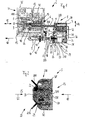
- schematisch eine Ansicht einer Infusionspumpe umfassend eine Antriebsvorrichtung mit einer Antriebskopfeinheit mit einer eine Zwei-Schwellenwert-Sensoreinheit umfassenden Detektiereinrichtung;
Figur 2- schematisch eine längsgeschnittene Ansicht eines vorderen Bereichs der Antriebskopfeinheit;
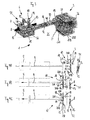
Figur 3- schematisch eine perspektivische teilweise geschnittene Ansicht der Antriebsvorrichtung der Infusionspumpe aus den
Figuren 1 und 2 mit der Antriebskopfeinheit und mit der Vortriebseinrichtung hierfür; - Figur 4A
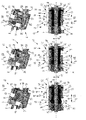
- schematisch eine Ansicht einer ersten Betriebsstellung der Antriebsvorrichtung aus den
Figuren 1 und 2 , bei welcher die Antriebskopfeinheit einer Kolbenplatte händisch zustellbar ist; - Figur 4B
- schematisch eine Ansicht einer gegenüber der ersten Betriebsstellung aus der
Figur 4A fortgeschrittenen zweiten Betriebsstellung, bei welcher ein Kontaktelement der Detektiereinrichtung in der Antriebskopfeinheit einen ersten Schwellenwert der Zwei-Schwellenwert-Sensoreinheit ausgelöst hat; - Figur 4C
- schematisch eine Ansicht einer gegenüber der zweiten Betriebsstellung aus der
Figur 4B fortgeschrittenen dritten Betriebsstellung, bei welcher das Kontaktelement einen zweiten Schwellenwert der Zwei-Schwellenwert-Sensoreinheit ausgelöst hat und darüber hinaus ein Drucksensor ausgelöst ist; - Figur 5A
- schematisch eine Detailansicht der Vortriebseinrichtung in der ersten Betriebsstellung hinsichtlich der
Figur 4A ; Figur 5B- schematisch eine Ansicht eines Längsschnitts der Detailansicht aus der
Figur 5A ; - Figur 6A
- schematisch eine Detailansicht der Vortriebseinrichtung in der zweiten Betriebsstellung hinsichtlich der
Figur 4B ; Figur 6B- schematisch eine Ansicht eines Längsschnitts der Detailansicht aus der
Figur 6A ; Figur 7A- schematisch eine Detailansicht der Vortriebseinrichtung in der dritten Betriebsstellung hinsichtlich der
Figur 4C ; und Figur 7B- schematisch eine Ansicht eines Längsschnitts der Detailansicht aus der
Figur 7A
- FIG. 1
- schematically a view of an infusion pump comprising a drive device with a drive head unit with a detecting device comprising a two-threshold sensor unit;
- FIG. 2
- schematically a longitudinal sectional view of a front portion of the drive head unit;
- FIG. 3
- schematically a perspective partially sectioned view of the drive device of the infusion pump from the
Figures 1 and 2 with the drive head unit and the propulsion device therefor; - FIG. 4A
- schematically a view of a first operating position of the drive device from the
Figures 1 and 2 in which the drive head unit of a piston plate is manually deliverable; - FIG. 4B
- schematically a view of a relation to the first operating position of the
FIG. 4A advanced second operating position, in which a contact element of the detection device in the drive head unit has triggered a first threshold value of the two-threshold sensor unit; - FIG. 4C
- schematically a view of a relative to the second operating position of the
FIG. 4B advanced third operating position, wherein the contact element has triggered a second threshold value of the two-threshold sensor unit and in addition a pressure sensor is triggered; - FIG. 5A
- schematically a detailed view of the propulsion device in the first operating position with respect to
FIG. 4A ; - FIG. 5B
- schematically a view of a longitudinal section of the detail view of the
FIG. 5A ; - FIG. 6A
- schematically a detailed view of the propulsion device in the second operating position with respect to
FIG. 4B ; - FIG. 6B
- schematically a view of a longitudinal section of the detail view of the
FIG. 6A ; - FIG. 7A
- schematically a detailed view of the propulsion device in the third operating position with respect to
FIG. 4C ; and - FIG. 7B
- schematically a view of a longitudinal section of the detail view of the
FIG. 7A ,
Die in den
Die Vortriebseinrichtung 6 umfasst im Wesentlichen einen Vortriebsschlitten 7, eine Vortriebsspindel 8 sowie eine mehrteilige Vortriebsspindelmutter 9. Darüber hinaus umfasst die Vortriebseinrichtung 6 noch einen Vortriebsmotor und ein entsprechendes Getriebe, welche vorliegend jedoch nicht dargestellt sind. Mit der Vortriebseinrichtung 6 wird eine lineare Zustellbewegung der Antriebskopfeinheit 3 umgesetzt. Mit dem Vortriebsschlitten 7 sind die lineare Führung und der Verdrehschutz der Antriebskopfeinheit 3 gewährleistet.The
Die mehrteilige Vortriebsspindelmutter 9 bzw. der Vortriebsschlitten 7 können bei entsprechend gewählter Drehrichtung der Vortriebsspindel 8 in Kolbenantriebsrichtung 10 vorwärts angetrieben werden, wobei insbesondere die mehrteilige Vortriebsspindelmutter 9 axial entlang der Längserstreckung 11 der Vortriebsspindel 8 bewegt wird.The multi-part driving spindle nut 9 or the driving
Die mehrteilige Vortriebsspindelmutter 9 umfasst hierbei eine erste radial bewegbare Mutterschale 12 und eine zweite radial bewegbare Mutterschale 13, wie später noch ausführlicher beschrieben ist. Jedenfalls können die radial bewegbaren Mutterschalen 12 und 13 einen axialen Formschluss mit der Vortriebsspindel 8 gewährleisten und diesen jedoch auch aufheben. Hierzu sind die beiden radial bewegbaren Mutterschalen 12 und 13 in dem Vortriebsschlitten 7 gegenüber der Vortriebsspindel 8 einrückbar bzw. ausrückbar gelagert angeordnet.The multi-part driving spindle nut 9 in this case comprises a first radially
Der Begriff "radial" kennzeichnet eine radiale Bewegungsrichtung 14 im Wesentlichen quer zur Längserstreckung 11 der Vortriebsspindel 8.The term "radial" denotes a
Die Vortriebsspindel 8 weist ferner ein Außengewinde 15 auf, mittels welchem die mehrteilige Vortriebsspindelmutter 9 formschlüssig verbunden werden kann.The driving
Die Antriebskopfeinheit 3 ist mittels eines Haltearms 16 an dem Vortriebsschlitten 7 befestigt, sodass diese zusammen mit dem Vortriebsschlitten 7 entsprechend axial verschieblich ist.The
Die Antriebskopfeinheit 3 weist zudem eine Hauptanlageeinrichtung 17 zum Abstützen einer Kolbenplatte 18 des Infusionsspritzenkolbens 4 auf. An die Hauptanlageeinrichtung 17 stützt sich die Kolbenplatte 18 ab, wenn der Infusionsspritzenkolben 4 von der Antriebskopfeinheit 3 in Kolbenantriebsrichtung 10 geschoben wird. Die Hauptanlageeinrichtung 17 gestaltet hierfür eine Hauptanlagefläche 19 aus, an welcher sich die Kolbenplatte 18 abstützt.The
Hierbei wird die Kolbenplatte 18 mittels einer Fixiereinrichtung 20 an der Antriebskopfeinheit 3 fixiert, sodass eine formschlüssige Verbindung zwischen der Kolbenplatte 18 des Infusionsspritzenkolbens 4 und der Antriebskopfeinheit 3 garantiert ist.Here, the
Die Fixiereinrichtung 20 ist hierbei mit Mitteln 21 zum Auslösen der Fixiereinrichtung 20 ausgestattet, welche einen Membranteller 22 umfassen, der wiederum einen Drucksensor 22A zur Verfügung stellt, mittels welchem ein Anschlagsdruck bzw. ein Anlagedruck hinsichtlich der Kolbenplatte 18 gegenüber der Hauptanlageeinrichtung 17 detektiert werden kann. Wird ein entsprechender Druck registriert, wird eine Bewegung von Fixierbügeln 20A und 20B der Fixiereinrichtung 20 ausgelöst, die dann nach innen zuschnappen und die Kolbenplatte 18 an der Hauptanlagefläche 19 form- und kraftschlüssig festlegen (siehe auch Figuren 2C und
Während die Mittel 21 zum Auslösen der Fixiereinrichtung 20 insbesondere mit ihrem Membranteller 22 und ihrem Drucksensor 22A im Allgemeinen einer Detektiereinrichtung 23 der Antriebskopfeinheit 3 zugeordneter werden können, zeichnet sich die Detektiereinrichtung 23 speziell durch eine Mehr-Schwellenwert-Sensoreinheit 24 zum Detektieren des Infusionsspritzenkolbens 4 im Vorfeld 25 vor der Hauptanlageeinrichtung 17 aus.While the
Die Detektiereinrichtung 23 weist darüber hinaus ein Feder 26 vorgespanntes axial verlagerbares Geberelement 27 zum Beeinflussen der Mehr-Schaltschwellen-Sensoreinheit 24 auf. Das Geberelement 27 ist hierbei konstruktiv einfach direkt durch ein Kontaktelement 27A der Antriebskopfeinheit 3 ausgestaltet, welches über die Hauptanlageeinrichtung 17 hinaus bis in das Vorfeld 25 hinein ragt.The
Die Mehr-Schaltschwellen-Sensoreinheit 25 zeichnet sich hierbei durch eine mindestens zweistufige Vorfelderfassungseinrichtung 28 auf, welche mit einer ersten Lichtschranke 29 und einer zweiten Lichtschranke 30 ausgerüstet ist, die axial hintereinander angeordnet sind, wodurch sie beide konstruktiv besonders einfach von dem einzigen Geberelement 27 beeinflussbar sind.The
Während einerseits mittels des Drucksensors 22A des Membrantellers 22 die Funktion eines Antriebsgetriebes 31 der Fixiereinrichtung 20 gesteuert werden kann, kann andererseits mittels der Mehr-Schwellenwert-Sensoreinheit 24 die Funktion der Vortriebseinrichtung 6 beeinflusst werden, wie später noch detaillierter beschrieben ist. Hierzu ist die Mehr-Schwellenwert-Sensoreinheit 24 über eine entsprechende Signalleitung 32 mit einer Steuerungseinheit 33 der Vortriebseinrichtung 6 verbunden.While the function of a
Vorteilhafter Weise umfasst die Antriebsvorrichtung 1 noch eine übergeordnete in Abhängigkeit der Detektiereinrichtung 23 arbeitende gemeinsame Regel- und Steuereinrichtung 34 zum automatischen radialen Einrücken der beiden radial bewegbaren Mutterschalen 12 und 13 an der Vortriebsspindel 8 und zum Initiieren einer mittels der radial eingerückten Vortriebsspindelmutter 9 durchführbaren Referenzfahrt der Hauptanlageeinrichtung 17 bis an Infusionsspritzenkolben 4 heran. Die gemeinsame Regel- und Steuereinrichtung 34 ist nach der Darstellung der
Die gemeinsame Regel- und Steuereinrichtung 34 zeichnet sich noch durch eine Komparatorschaltungseinheit 36 zum Schalten von Elektrohaltemagneten 80 bzw. 81 (siehe
An der Antriebskopfeinheit 3 ist noch ein manuell bedienbarer Bedienhebel 36 vorgesehen, mittels welchen die Funktionen der Fixierbügel 20A und 20B sowie der Vortriebseinrichtung 6 zusätzlich manuell betätigt werden können. Zur mechanischen Betätigung der Vortriebseinrichtung 6 mittels des Bedienhebels 36 ist dieser von der Antriebskopfeinheit 3 durch den Haltearm 16 hindurch bis zur Vortriebseinrichtung 6 geführt.At the
Auf die speziell in der
An dem Infusionspumpengehäuse 35 von außen zugänglich ist noch eine Aufnahme 42 für die Infusionsspritze 5 vorgesehen, welche einen Klemmbügel 43 zum radialen Festlegen der Infusionsspritze 5 und eine Klemmlasche 44 zum axialen Festlegen der Infusionsspritze 5 an der Aufnahme 42 der Infusionspumpe 2 umfasst.A receptacle 42 for the
Bei der in der
Die erste Lichtschranke 29 ist mittels einer ersten elektrischen Kabelverbindung 29A der Signalleitung 32 (siehe
Das Geberelement 27 ist in dieser Darstellung aufgrund eines Kontaktes mit der hier nicht gezeigten Kolbenplatte 18 gemäß der Pfeilrichtung 50 derart weit in die Antriebskopfeinheit 3 hinein verlagert, dass es bereits die zweite Lichtschranke 30 unterbrochen hat. Insofern befindet sich die Antriebsvorrichtung 1 in der zweiten Betriebsstellung 61, welche später noch genauer erläutert ist.In this illustration, the
Deutlich ist das in dem Membranteller 22 beweglich integrierte Geberelement 27 der zweistufigen Vorfelderkennungseinrichtung 28 zu erkennen, welches relativ verschieblich zu dem Membranteller 22 gelagert ist.The
Da der hinter dem Membranteller 22 angeordnete Drucksensor 22A noch nicht ausreichend stark von der Kolbenplatte 18 gedrückt ist, befinden sich die beiden Fixierbügel 20A und 20B der Fixiereinrichtung 20 noch in der geöffneten Stellung (siehe auch
Im Folgenden werden die funktionalen Zusammenhänge der vorliegenden Antriebsvorrichtung 1 speziell hinsichtlich der
Die Blockiereinrichtung 51 weist ein axial verschiebliches Betätigungselement 52 auf, welches hier beispielhaft zumindest eine axial verschiebliche Auslösehülse 53 umfasst, die konzentrisch um die beiden Mutterschalen 12 und 13 der Vortriebsspindelmutter 9 herum angeordnet ist. Die Auslösehülse 53 ist hierbei in Längserstreckung 11 der Vortriebsspindel 8 verschieblich radial außen an der Vortriebsspindelmutter 9 gelagert.The blocking
Damit die Blockiereinrichtung 51 extrem schnell aktiviert werden kann, verfügt sie über Mittel 54 zum Beschleunigen der Auslösehülse 53, wobei die Beschleunigungsmittel 54 konstruktiv einfach durch eine Spiralfeder 55 ausgestaltet sind, die wiederum radial außen an der Auslösehülse 53 gelagert ist.So that the blocking
Darüber hinaus verfügt das Betätigungselement 52 noch über eine Freigabehülse 56, die ebenfalls axial verschieblich und konzentrisch um die beiden Mutterschalen 12 und 13 der Vortriebsspindelmutter 9 herum angeordnet sein kann.In addition, the
Insofern sind beide Schiebehülsen 53 und 56 auch axial in Bezug auf die Längserstreckung 57 der beiden radial bewegbaren Mutterschalen 12 und 13 verschieblich gelagert.In this respect, both sliding
Zum besseren Verständnis der Funktionsweise des vorliegenden Betätigungselements 52 der Vortriebsspindelmutter 9 im Zusammenhand mit der Funktion der Mehr-Schwellenwert-Sensoreinheit 24 ist in den
Bei einer in den
Letztlich befindet sich bei einer weiteren hinsichtlich der
Betrachtet man nun die Darstellungen aller
Um die beiden radial bewegbaren Mutterschalen 12, 13 jeweils mit den beiden Schiebehülsen 53, 56 gegenüber der Vortriebsspindel 8 um eine Kippachse 66, welche im Wesentlichen quer zu Längserstreckung 57 der jeweiligen Mutterschale 12 bzw. 13 verläuft, herum radial anstellen zu können, sind die beiden Mutterschalen 12 und 13 endseitig 67 jeweils auf einem Vortriebsschlittenlager 68 gelagert. Die Kippachse 66 erstreckt sich nach der Darstellung der
Darüber hinaus weist die Vortriebsspindelmutter 9 einen Kopfbereich 69 und einen Fußbereich 70 auf, deren jeweilige Außendurchmesser größer sind als ein dazwischen angeordnetes Vortriebsspindelmuttergebiet 71, wobei der Kopfbereich 69 eine Rampe 72 zum Aufschieben für die beiden axial verschieblichen Schiebehülsen 53 und 56 und der Fußbereich 70 ein Gegenlager 73 für die beiden axial verschieblichen Schiebehülsen 53 und 56 ausgestaltet.In addition, the drive spindle nut 9 has a head region 69 and a
An einem dem Vortriebsschlittenlager 68 gegenüberliegenden Vortriebsspindelmutterende 74 befindet sich eine an dem Vortriebsschlitten 7 gelagerte Parkeinrichtung 75 für die Freigabehülse 56, wobei die Parkeinrichtung 75 axial neben der Vortriebsspindelmutter 9 platziert ist. Ist die Freigabehülse 56 auf den Sitz der Parkeinrichtung 75 aufgeschoben und hierbei neben der Vortriebsspindelmutter 9 geparkt, befindet sich die Freigabehülse 56 in einer Öffenposition 76. Dies ist bei den beiden Betriebsstellungen 60 und 61 der Fall. Bei der dritten Betriebsstellung 62 ist die Freigabehülse 56 auf die Rampe 72 verschoben und sie befindet sich dementsprechend in einer Schließposition 77.A parking device 75 for the
Die Auslösehülse 53 befindet sich in den beiden Betriebsstellungen 60 und 62 jeweils in ihrer eigenen Öffenposition 78, in welcher die Auslösehülse 53 dem Gegenlager 73 näher als der Rampe 72 zugewandt ist. Lediglich bei der Betriebsstellung 61 befindet sich die Auslösehülse 53 in einer ihr zugeteilten Schließposition 79.The
Des Weiteren umfasst die Vortriebseinrichtung 8 ein erstes Elektrohaltemagnet 80 und ein zweites Elektrohaltemagnet 81, welche in diesem Ausführungsbeispiel oberhalb des Vortriebsschlittens 7 angeordnet sind.Furthermore, the
Der erste Elektrohaltemagnet 80 ist hierbei der Auslösehülse 53 zugeordnet und er kann dementsprechend mit einem Magnetteller 82 der Auslösehülse 53 korrespondieren. Hierzu ist der Magnetteller 82 vor dem ersten Elektrohaltemagnet 80 platziert und gekoppelt mit der Auslösehülse 53 axial verschieblich gelagert. Bei den beiden Betriebsstellungen 60 und 62 ist der erste Elektrohaltemagnet 80 bestromt, sodass er mit dem Magnetteller 82 Kontakt halten und damit auch die Auslösehülse 53 in ihrer Öffenposition 78 halten kann. Bei der zweiten Betriebsstellung 61 ist der Magnetteller 82 von dem ersten unbestromten Elektrohaltemagneten 80 beabstandet.The first
Der zweite Elektrohaltemagnet 81 ist dementsprechend der Freigabehülse 56 zugeordnet und er kann mit einem Magnetteller 83 der Freigabehülse 56 korrespondieren, wobei dieser Magnetteller 83 hierzu vor dem zweiten Elektrohaltemagnet 81 platziert ist. Der Magnetteller 83 wird gemeinsam mit der Freigabehülse 56 axial verschoben, da er mit dieser gekoppelt ist. Insofern befindet sich der Magnetteller 83 bei den Betriebsstellungen 60 und 61 in Kontakt mit dem zweiten bestromten Elektrohaltemagnet 81, während er bei der zweiten Betriebsstellung 62 von dem unbestromten zweiten Elektrohaltemagnet 81 entfernt angeordnet ist.Accordingly, the second
Ist nun ein Infusionsspritzenwechsel gewünscht bzw. erforderlich, wird die Infusion gestoppt. Anschließend wird der Bedienhebel 36 an der Antriebskopfeinheit 3 betätigt. Mit dem Betätigen des Bedienhebels 36 wird über den Haltearm 16, welcher als Rohr 90 (siehe
Anschließend wird der Klemmbügel 43 geöffnet und entsprechend verschwenkt, sodass die Aufnahme 42 gut zugänglich ist. Ein im Inneren des Infusionspumpengehäuses 35 montiertes Potentiometer 97 erkennt den Zustand des Klemmbügels 43 (siehe
Nun kann die Antriebskopfeinheit 3 entsprechend des Füllstands der Infusionsspritze 5 und damit auch der Position des Infusionsspritzenkolbens 4 an die Kolbenplatte 18 heran geführt werden. Damit hierbei größere Abstände zwischen der Antriebskopfeinheit 3 und der Kolbenplatte 18 schneller überwunden werden können, kann dies durch eine händische Zustellbewegung in Kolbenantriebsrichtung 10 geschehen, da die beiden radial bewegbaren Mutterschalen 12 und 13 sich nicht im Eingriff mit dem Außengewinde 15 der Vortriebsspindel 8 befinden, wie dies bei der ersten Betriebsstellung 60 gemäß der
Sobald jedoch das Kontaktelement 27A mit der Kolbenplatte 22 in Kontakt tritt (siehe
Beim Durchfahren der ersten Lichtschranke 29 (siehe weiter
Jedoch fährt die Vortriebseinrichtung 6 jetzt automatisch weiter, bis das Geberelement 27 die zweite Lichtschranke 30 durchfährt (siehe insbesondere
Bei dieser Referenzfahrt im Sinne der Erfindung befindet sich die Vortriebseinrichtung 6 in der zweiten Betriebsstellung 61, bei welcher der erste Elektrohaltemagnet 80 stromlos, der zweite Elektrohaltemagnet 81 jedoch bestromt ist. Beide Schiebehülsen 53 und 56 sind im Vortriebsschlitten 7 nach links verschoben und die beiden Mutterschalen 12 und 13 sind radial geschlossen. Die Fixiereinrichtung 20 an der Antriebskopfeinheit 3 ist noch geöffnet (siehe
Die Antriebskopfeinheit 3 fährt den abgeglichenen Weg von der zweiten Lichtschranke 30 bis zum Membranteller 22 und dem dahinter angeordneten Drucksensor 22A ab, mittels welchem ein korrektes Anliegen der Kolbenplatte 18 an der Hauptanlagefläche 19 an der Antriebskopfeinheit 3 detektiert und signalisiert wird (siehe
Der zweite Elektrohaltemagnet 81 wird stromlos geschaltet, die Freigabehülse 56 verlagert sich in ihre Schließposition 77 (siehe insbesondere
Mittels des Klemmbügels 43 und dem Potentiometer 97 ist bereits der Infusionsspritzendurchmesser gemessen worden, sodass in einem Display (hier nicht gezeigt) der Infusionspumpe 2 eine Auswahl an entsprechenden Infusionsspritzen 5 vorgeschlagen wird. Nach einer Bestätigung der gültigen Infusionsspritze 5 kann die gewünschte Infusionstherapie eingegeben werden und es kann nun die Infusion gestartet werden, wobei sich die Antriebskopfeinheit 3 und die Vortriebseinrichtung 6 in der dritten Betriebsstellung 62 gemäß der Figuren 4C, 7A und 7B befindet. In der dritten Betriebsstellung 62 ist die Vortriebseinrichtung 6 somit verriegelt. Dies bedeutet, dass die beiden Elektrohaltemagnete 80, 81 stromlos sind.By means of the clamp 43 and the
Besonders vorteilhaft ist es, dass hierbei ein energieloser Zustand hinsichtlich der beiden Elektrohaltemagnete 80, 81 vorliegt, sodass ein Funktionieren der dritten Betriebsstellung 62 auch ohne Bestromen der Elektrohaltemagnete 80, 81 gewährleistet werden kann. Die beiden Schiebehülsen 53, 56 sind innerhalb des Vortriebsschlittens 7 nach rechts verschoben, da die weitere Feder 92 stärker ausgelegt ist als die Spiralfeder 55. Die beiden Mutterschalen 12 und 13 bleiben radial verschlossen sowie auch die Fixiereinrichtung 23 an der Antriebskopfeinheit 3 verschlossen ist.It is particularly advantageous that in this case there is an energy-free state with regard to the two
Damit die Elektrohaltemagnete 80 und 81 besonders schnell stromlos geschaltet werden können, umfasst die Antriebsvorrichtung 1 vorteilhafter Weise noch eine Komparatorschaltungseinheit 100 (siehe Figur 100). Da das jeweilige Magnetfeld der Elektrohaltemagnete 80 und 81 mit Hilfe der Bestromung erzeugt wird, ist es vorteilhaft, wenn für ein schnelles Abklingen der Bestromung eine kurzzeitige Überspannung zugelassen wird. Mittels der Komparatorschaltungseinheit 100 wird ein besonders rasches Abfallen des Energiezustands an dem jeweiligen Elektrohaltemagnet 80 bzw. 81 erzielt, sodass sich die Reaktionszeit zum Blockieren der Vortriebseinrichtung 6 weiter verringern lässt.In order that the
Es versteht sich, dass es sich bei dem vorstehend erläuterten Ausführungsbeispiel lediglich um eine erste Ausgestaltung der erfindungsgemäßen Antriebsvorrichtung handelt. Insofern beschränkt sich die Ausgestaltung der Erfindung nicht auf dieses Ausführungsbeispiel.It goes without saying that the exemplary embodiment explained above is only a first embodiment of the drive device according to the invention. In this respect, the embodiment of the invention is not limited to this embodiment.
Sämtliche in den Anmeldungsunterlagen offenbarten Merkmale werden als erfindungswesentlich beansprucht, sofern sie einzeln oder in Kombination gegenüber dem Stand der Technik neu sind.All disclosed in the application documents features are claimed as essential to the invention, provided they are new individually or in combination over the prior art.
- 11
- Antriebsvorrichtungdriving device
- 22
- Infusionspumpeinfusion pump
- 33
- AntriebskopfeinheitDrive head unit
- 3A3A
- AntriebskopfeinheitsgehäuseDrive head unit housing
- 44
- InfusionsspritzenkolbenInfusion syringe plunger
- 55
- Infusionsspritzeinfusion syringe
- 66
- Vortriebseinrichtungpropulsor
- 77
- Vortriebsschlittendriving slide
- 88th
- Vortriebsspindeldriving spindle
- 99
- mehrteilige Vortriebsspindelmuttermulti-part driving spindle nut
- 1010
- KolbenantriebsrichtungPiston drive direction
- 1111
- Längserstreckunglongitudinal extension
- 1212
- erste Mutterschalefirst nutshell
- 1313
- zweite Mutterschalesecond nutshell
- 1414
- radiale Bewegungsrichtungradial direction of movement
- 1515
- Außengewindeexternal thread
- 1616
- Haltearmholding arm
- 1717
- HauptanlageeinrichtungMain plant equipment
- 1818
- Kolbenplattepiston plate
- 1919
- HauptanlageflächePrincipal Investment Area
- 2020
- Fixiereinrichtungfixing
- 20A20A
- erster Fixierbügelfirst fixing bracket
- 20B20B
- zweiter Fixierbügelsecond fixing bracket
- 2121
- Mittel zum AuslösenMeans of triggering
- 2222
- Membrantellerdiaphragm plate
- 22A22A
- Drucksensorpressure sensor
- 2323
- Detektiereinrichtungdetection
- 2424
- Mehr-Schwellenwert-SensoreinheitMore threshold sensor unit
- 2525
- Vorfeldadvance
- 2626
- Federfeather
- 2727
- Geberelementtransmitter element
- 27A27A
- Kontaktelementcontact element
- 2828
- VorfelderfassungseinrichtungAdvance detector
- 2929
- erste Lichtschrankefirst photocell
- 29A29A
- erste Kabelverbindungfirst cable connection
- 3030
- zweite Lichtschrankesecond photocell
- 30A30A
- zweite Kabelverbindungsecond cable connection
- 3131
- Antriebsgetriebedrive gear
- 3232
- Signalleitungsignal line
- 3333
- Steuerungseinheitcontrol unit
- 3434
- gemeinsame Regel- und/oder Steuereinrichtungcommon control and / or control device
- 3535
- InfusionspumpengehäuseInfusion pump housing
- 3636
- Bedienhebeloperating lever
- 4040
- Sensor zum FeststellenSensor for detection
- 4141
- FormschlusssensorPositive locking sensor
- 4242
- Aufnahmeadmission
- 4343
- Klemmbügelclamp
- 4444
- Klemmlascheclamping plate
- 5050
- Pfeilrichtungarrow
- 5151
- Blockiereinrichtungblocking device
- 5252
- Betätigungselementactuator
- 5353
- Auslösehülsetrigger sleeve
- 5454
- Beschleunigungsmittelaccelerators
- 5555
- Spiralfeder bzw. AuslösehülsefederSpiral spring or release sleeve spring
- 5656
- FreigabehülseA release sleeve
- 5757
- Längserstreckunglongitudinal extension
- 6060
- erste Betriebsstellungfirst operating position
- 6161
- zweite Betriebsstellungsecond operating position
- 6262
- dritte Betriebsstellungthird operating position
- 6464
- Eingreifbereichengaging portion
- 6565
- Auflagebereichsupport area
- 6666
- Kippachsetilt axis
- 6868
- VortriebsschlittenlagerPropulsion slide bearings
- 6969
- Kopfbereichhead area
- 7070
- Fußbereichfooter
- 7171
- VortriebsspindelmuttergebietJacking nut area
- 7272
- Ramperamp
- 7373
- Gegenlagerthrust bearing
- 7474
- VortriebsspindelmutterendeJacking nut end
- 7575
- ParkeinrichtungPark facility
- 7676
- ÖffenpositionÖffenposition
- 7777
- Schließpositionclosed position
- 7878
- weitere Öffenpositionfurther opening position
- 7979
- weitere Schließpositionfurther closed position
- 8080
- erster Elektrohaltemagnet bzw. Auslösehülsemagnetfirst electric holding magnet or tripping sleeve magnet
- 8181
- zweiter Elektrohaltemagnet bzw. Freigabehülsemagnetsecond electric holding magnet or release sleeve magnet
- 8282
- erster Magnettellerfirst magnetic disk
- 8383
- zweiter Magnettellersecond magnetic dish
- 9090
- Rohrpipe
- 9191
- Fixierungswellefixing shaft
- 9292
- weitere Feder bzw. Freigabehülsefederanother spring or release sleeve spring
- 9393
- erstes Elektrokabelfirst electric cable
- 9494
- zweites Elektrokabelsecond electric cable
- 9797
- Potentiometerpotentiometer
- 100100
- KomparatorschaltungseinheitKomparatorschaltungseinheit
Claims (14)
- A drive device (1) for linear movement of an infusion syringe piston (4) of an infusion syringe (5) arranged at an infusion pump (2) comprising a drive head unit (3) including a main bearing means (17) for supporting the infusion syringe piston (4), a fixing means (20) for fixing the infusion syringe piston (4) on the main bearing means (17) as well as means (21) for triggering the fixing means (20) and comprising an advancing means (6) for the drive head unit (1) including a motor-drivable advancing spindle (8) and a multi-part advancing spindle nut (9) including at least one radially movable nut shell (12, 13), wherein the drive head unit (3) in addition comprises detecting means (23) for detecting the infusion syringe piston (4) ahead of the main bearing means (17),
characterized in that
the detecting means (23) includes a multi-threshold sensor unit (24) having an at least two-stage upstream detection means (28) for detecting different positions of the infusion syringe piston (4) before a piston plate (18) of the infusion syringe piston (4) enters into contact with the main bearing means (17). - The drive device (1) according to claim 1,
characterized in that
the multi-threshold sensor unit (24) includes at least two sensors (29, 30) to be triggered by means of one single transmitter element (27), said transmitter element (27) comprising a contact element (27A) projecting from the main bearing means (17). - The drive device (1) according to claim 1 or 2,
characterized in that
the detecting means (23) comprises at least two light barriers (29, 30) which are arranged axially in series within the drive head unit (3). - The drive device (1) according to claim 3,
characterized in that
at least either of the two light barriers (29, 30) is a fork light barrier. - The drive device (1) according to any one of the claims 1 to 4,
characterized in that
the main bearing means (17) includes a diaphragm plate (22) comprising a transmitter element (27) including a contact element (27A) for switching sensors (29, 30) of the multi-threshold sensor unit (24). - The drive device (1) according to any one of the claims 1 to 5,
characterized in that
one single transmitter element (27) of the multi-threshold sensor unit (24) is arranged inside the means (21) for triggering the fixing means (20). - The drive device (1) according to any one of the clams 1 to 6,
characterized in that
one single transmitter element (27) of the multi-threshold sensor unit (24) has a pre-travel of a value between 2 mm and 10 mm, preferably of a value of 4 mm, before a first stage of the two-stage upstream detection means (28) can be triggered by the single transmitter element (27). - The drive device (1) according to any one of the claims 1 to 7,
characterized in that
the drive device (1) includes at least one joint control means (34) operating as a function of the detecting means (23) for automatic radial engagement of the at least one radially movable nut shell (12, 13) at the advancing spindle (8) and for initiating a reference travel of the main bearing means (17) to be carried out by means of the radially engaged advancing spindle nut (9) up to the infusion syringe piston (4). - The drive device (1) according to claim 8,
characterized in that
the joint control means (34) comprises a comparator circuit unit (100) for switching holding solenoids (80, 81). - The drive device (1) according to any one of the claims 1 to 9,
characterized in that
the advancing means (6) comprises holding solenoids (80, 81) controllable by means of the detecting means (23) for actuating axially movable sliding sleeves (53, 56) for radially engaging the advancing spindle nut (9) vis-à-vis the advancing spindle (8). - An infusion pump (2) comprising a drive head unit (3) for moving an infusion syringe piston (4) of an infusion syringe (5) disposed on the infusion pump (2) and comprising an advancing means (6) for driving the drive head unit (3),
characterized by
a drive device (1) according to any one of the preceding claims. - A method for start-up of an infusion syringe (5) on an infusion pump (2) comprising a drive head unit (3) for linear movement of an infusion syringe piston (4) in which at least one radially movable nut shell (12, 13) of an advancing spindle nut (9) is radially disengaged from an advancing spindle (8) of an advancing means (6) for driving the drive head unit (3) so that the drive head unit (3) of a piston plate (18) of the infusion syringe piston (4) can be quickly axially fed by hand and in which for preventing inadvertent bolus administration the piston plate (18) can be detected by a detecting means (23) including a multi-threshold sensor unit (24) and an at least two-stage upstream detection means (28) associated with the drive head unit (3), before the piston plate (18) enters into contact with a main bearing surface (19) of a main bearing means (17) of the drive head unit (3), wherein- in a first detecting step a contact element (27A) of the detecting means (23) triggers a first sensor element (29), thereby the manual feeding of the drive head unit (3) by means of the advancing spindle nut (9) and the advancing spindle (8) being blocked in that the at least one radially movable nut shell (12, 13) is radially engaged on the advancing spindle (8), wherein then the drive head unit (3) of the piston plate (18) is further fed by motor drive manner via the advancing means (6),- in a second detecting step the contact element (27A) triggers a second sensor element (30), thereby a motor-driven reference travel of the drive head unit (3) up to the main bearing surface (19) of the main bearing unit (17) being initiated, and- in a third detecting step the motor-driven reference travel is stopped in the course of contact of the piston plate (18) with the main bearing surface (19) and retaining brackets (20A, 20B) of a fixing means (20) for the piston plate (18) are closed, thereby the piston plate (18) being secured to the main bearing means (17).
- The method according to claim 12,
characterized in that
the manual infeed of the drive head unit (3) is blocked, before the contact element (27A) triggers the second sensor element (30). - The method according to claim 12 or 13,
characterized in that
the motor-driven reference travel is carried out by way of a defined number of motor steps.
Priority Applications (7)
| Application Number | Priority Date | Filing Date | Title |
|---|---|---|---|
| EP11181527.0A EP2599511B1 (en) | 2011-11-30 | 2011-11-30 | Drive device for linear movement of an infusion syringe plunger, infusion pump and method for replacement of an infusion syringe |
| CN201280059301.0A CN104023767B (en) | 2011-11-30 | 2012-08-07 | For the linearly moving driving means of infusion syringe piston, infusion pump and for the method changing infusion syringe |
| BR112014012408-6A BR112014012408B1 (en) | 2011-11-30 | 2012-08-07 | drive device for linear movement of an infusion syringe piston, infusion pump and method for replacing an infusion syringe |
| JP2014543809A JP6010626B2 (en) | 2011-11-30 | 2012-08-07 | Drive device for linear movement of infusion syringe piston, infusion pump, and method for replacing an infusion syringe |
| RU2014126421A RU2612926C2 (en) | 2011-11-30 | 2012-08-07 | Linear drive for piston application in infusion syringe of infusion pump and method of replacement of infusion syringe |
| PCT/EP2012/065449 WO2013079226A1 (en) | 2011-11-30 | 2012-08-07 | Drive device for the linear movement of an infusion syringe piston, infusion pump and method for replacing an infusion syringe |
| US14/359,506 US9352083B2 (en) | 2011-11-30 | 2012-08-07 | Drive device for the linear movement of an infusion syringe piston, infusion pump and method for replacing an infusion syringe |
Applications Claiming Priority (1)
| Application Number | Priority Date | Filing Date | Title |
|---|---|---|---|
| EP11181527.0A EP2599511B1 (en) | 2011-11-30 | 2011-11-30 | Drive device for linear movement of an infusion syringe plunger, infusion pump and method for replacement of an infusion syringe |
Publications (2)
| Publication Number | Publication Date |
|---|---|
| EP2599511A1 EP2599511A1 (en) | 2013-06-05 |
| EP2599511B1 true EP2599511B1 (en) | 2014-08-13 |
Family
ID=46614498
Family Applications (1)
| Application Number | Title | Priority Date | Filing Date |
|---|---|---|---|
| EP11181527.0A Active EP2599511B1 (en) | 2011-11-30 | 2011-11-30 | Drive device for linear movement of an infusion syringe plunger, infusion pump and method for replacement of an infusion syringe |
Country Status (7)
| Country | Link |
|---|---|
| US (1) | US9352083B2 (en) |
| EP (1) | EP2599511B1 (en) |
| JP (1) | JP6010626B2 (en) |
| CN (1) | CN104023767B (en) |
| BR (1) | BR112014012408B1 (en) |
| RU (1) | RU2612926C2 (en) |
| WO (1) | WO2013079226A1 (en) |
Cited By (2)
| Publication number | Priority date | Publication date | Assignee | Title |
|---|---|---|---|---|
| DE102016115608A1 (en) | 2016-08-23 | 2018-03-01 | B. Braun Melsungen Ag | Syringe pump with improved syringe loading procedure to prevent unwanted bolus administration |
| EP3509667B1 (en) | 2016-09-07 | 2020-07-01 | Fresenius Vial SAS | Infusion device having a clutching device |
Families Citing this family (9)
| Publication number | Priority date | Publication date | Assignee | Title |
|---|---|---|---|---|
| WO2014106008A1 (en) | 2012-12-28 | 2014-07-03 | Gambro Renal Products, Inc. | Syringe pump engagement detection apparatus and methods |
| KR101524678B1 (en) * | 2014-04-29 | 2015-06-03 | 최규동 | Short Length Driver for Injection Appartus |
| CN105107053B (en) * | 2015-09-07 | 2018-01-12 | 张明 | Pump is injected in a kind of full-automatic mixing |
| WO2017135936A1 (en) * | 2016-02-02 | 2017-08-10 | Perqflo, Llc | Hybrid ambulatory infusion pump with contactless power transmission |
| DE102016115268A1 (en) * | 2016-08-17 | 2018-02-22 | B. Braun Melsungen Ag | Method for controlling a syringe pump |
| DE102017111301A1 (en) * | 2017-05-23 | 2018-11-29 | B. Braun Melsungen Ag | sensor system |
| JP7295840B2 (en) | 2017-07-19 | 2023-06-21 | スミスズ メディカル エーエスディー,インコーポレイティド | Housing structure for infusion pump |
| CN109621080B (en) * | 2019-01-30 | 2023-09-15 | 深圳中科生物医疗电子有限公司 | Infusion pump |
| DE102021118221A1 (en) | 2021-07-14 | 2023-01-19 | B. Braun Melsungen Aktiengesellschaft | Syringe pump and method for improved loading of a syringe |
Family Cites Families (8)
| Publication number | Priority date | Publication date | Assignee | Title |
|---|---|---|---|---|
| EP0514907B1 (en) * | 1991-05-23 | 1996-07-10 | Ivac Corporation | Syringe plunger driver system |
| RU2012358C1 (en) * | 1991-09-10 | 1994-05-15 | Александр Николаевич Шариков | Device for injecting medicinal preparations |
| JPH06197959A (en) * | 1992-12-28 | 1994-07-19 | Sanyo Electric Works Ltd | Automatic medical fluid injector |
| AUPM348594A0 (en) | 1994-01-21 | 1994-02-17 | University Of Melbourne, The | Improvements in syringe pumps |
| JP3933832B2 (en) * | 1999-12-24 | 2007-06-20 | テルモ株式会社 | Syringe pump |
| DE20200885U1 (en) | 2002-01-22 | 2003-05-28 | Braun Melsungen Ag | Syringe pump with piston brake |
| EP2093785B1 (en) * | 2008-02-22 | 2013-10-30 | Delphi Technologies, Inc. | Multi-function electrical input device |
| FR2950811B1 (en) | 2009-10-02 | 2012-10-26 | Fresenius Vial | ANTIBOLUS CONTROL METHOD AND CORRESPONDING DEVICE |
-
2011
- 2011-11-30 EP EP11181527.0A patent/EP2599511B1/en active Active
-
2012
- 2012-08-07 US US14/359,506 patent/US9352083B2/en active Active
- 2012-08-07 JP JP2014543809A patent/JP6010626B2/en active Active
- 2012-08-07 WO PCT/EP2012/065449 patent/WO2013079226A1/en active Application Filing
- 2012-08-07 BR BR112014012408-6A patent/BR112014012408B1/en active IP Right Grant
- 2012-08-07 RU RU2014126421A patent/RU2612926C2/en active
- 2012-08-07 CN CN201280059301.0A patent/CN104023767B/en active Active
Cited By (4)
| Publication number | Priority date | Publication date | Assignee | Title |
|---|---|---|---|---|
| DE102016115608A1 (en) | 2016-08-23 | 2018-03-01 | B. Braun Melsungen Ag | Syringe pump with improved syringe loading procedure to prevent unwanted bolus administration |
| WO2018036875A1 (en) | 2016-08-23 | 2018-03-01 | B. Braun Melsungen Ag | Syringe pump with improved insertion of syringes for avoiding unwanted bolus administration |
| EP3509667B1 (en) | 2016-09-07 | 2020-07-01 | Fresenius Vial SAS | Infusion device having a clutching device |
| EP3509667B2 (en) † | 2016-09-07 | 2023-04-26 | Fresenius Vial SAS | Infusion device having a clutching device |
Also Published As
| Publication number | Publication date |
|---|---|
| RU2612926C2 (en) | 2017-03-13 |
| EP2599511A1 (en) | 2013-06-05 |
| JP6010626B2 (en) | 2016-10-19 |
| BR112014012408A2 (en) | 2017-06-06 |
| US9352083B2 (en) | 2016-05-31 |
| US20150094665A1 (en) | 2015-04-02 |
| WO2013079226A1 (en) | 2013-06-06 |
| JP2014533595A (en) | 2014-12-15 |
| BR112014012408B1 (en) | 2021-01-26 |
| RU2014126421A (en) | 2016-01-27 |
| CN104023767B (en) | 2016-11-23 |
| CN104023767A (en) | 2014-09-03 |
Similar Documents
| Publication | Publication Date | Title |
|---|---|---|
| EP2599511B1 (en) | Drive device for linear movement of an infusion syringe plunger, infusion pump and method for replacement of an infusion syringe | |
| EP2606922B1 (en) | Infusion pump with drive device and blockage device for an infusion syringe piston drive head | |
| EP3307603B1 (en) | Vehicle steering system with steer-by-wire system and mechanical fallback system | |
| EP0432425B1 (en) | Infusion device | |
| EP1570933B1 (en) | Apparatus with a releasing unit for the actuation of a clamping device for tools | |
| EP0314880B1 (en) | Pressure infusion apparatus | |
| WO2013189655A1 (en) | Device for actuating a locking mechanism | |
| EP1499844B1 (en) | Device for electrically controlling an automatic weapon | |
| EP1619398B1 (en) | Positioning device, especially motor vehicle parking brake | |
| EP2631503A1 (en) | Disk brake with a lining wear adjustment device and method for adjusting an air gap | |
| WO2015082101A1 (en) | Actuator for activating a hydraulic clutch actuator and clutch which can be activated electrically | |
| EP3554707A1 (en) | Fitting a piston/cylinder unit on, and releasing one such from, a dispenser for receiving and dispensing volumes of fluid | |
| EP0566825A1 (en) | Pressure infusion apparatus | |
| WO2010023292A1 (en) | Arrangement for protecting a rotatable operating element in a motor vehicle from excessive rotation | |
| WO2018036875A1 (en) | Syringe pump with improved insertion of syringes for avoiding unwanted bolus administration | |
| DE4208483C1 (en) | ||
| WO2014166632A1 (en) | Truck mixer for concrete, mortar or similar, flowing materials | |
| EP2487393B1 (en) | Clamp valve | |
| EP4078638A1 (en) | Emergency-stop switch and machine with an emergency-stop switch | |
| EP3173668B1 (en) | Gearbox actuator for machine tool | |
| DE112014006231T5 (en) | Gurtschlossbringer | |
| EP4306147A1 (en) | Syringe pump with piston brake | |
| DE102021118224A1 (en) | Syringe pump and method of loading a syringe | |
| DE102017105481A1 (en) | injector | |
| DE102014221748B4 (en) | Method for monitoring the actuation of a hydraulically or pneumatically actuated component |
Legal Events
| Date | Code | Title | Description |
|---|---|---|---|
| PUAI | Public reference made under article 153(3) epc to a published international application that has entered the european phase |
Free format text: ORIGINAL CODE: 0009012 |
|
| AK | Designated contracting states |
Kind code of ref document: A1 Designated state(s): AL AT BE BG CH CY CZ DE DK EE ES FI FR GB GR HR HU IE IS IT LI LT LU LV MC MK MT NL NO PL PT RO RS SE SI SK SM TR |
|
| AX | Request for extension of the european patent |
Extension state: BA ME |
|
| 17P | Request for examination filed |
Effective date: 20131202 |
|
| RBV | Designated contracting states (corrected) |
Designated state(s): AL AT BE BG CH CY CZ DE DK EE ES FI FR GB GR HR HU IE IS IT LI LT LU LV MC MK MT NL NO PL PT RO RS SE SI SK SM TR |
|
| GRAP | Despatch of communication of intention to grant a patent |
Free format text: ORIGINAL CODE: EPIDOSNIGR1 |
|
| INTG | Intention to grant announced |
Effective date: 20140214 |
|
| INTG | Intention to grant announced |
Effective date: 20140221 |
|
| GRAS | Grant fee paid |
Free format text: ORIGINAL CODE: EPIDOSNIGR3 |
|
| GRAA | (expected) grant |
Free format text: ORIGINAL CODE: 0009210 |
|
| AK | Designated contracting states |
Kind code of ref document: B1 Designated state(s): AL AT BE BG CH CY CZ DE DK EE ES FI FR GB GR HR HU IE IS IT LI LT LU LV MC MK MT NL NO PL PT RO RS SE SI SK SM TR |
|
| REG | Reference to a national code |
Ref country code: GB Ref legal event code: FG4D Free format text: NOT ENGLISH |
|
| REG | Reference to a national code |
Ref country code: CH Ref legal event code: EP Ref country code: CH Ref legal event code: NV Representative=s name: ROTTMANN, ZIMMERMANN + PARTNER AG, CH Ref country code: AT Ref legal event code: REF Ref document number: 681801 Country of ref document: AT Kind code of ref document: T Effective date: 20140815 |
|
| REG | Reference to a national code |
Ref country code: IE Ref legal event code: FG4D Free format text: LANGUAGE OF EP DOCUMENT: GERMAN |
|
| REG | Reference to a national code |
Ref country code: DE Ref legal event code: R096 Ref document number: 502011004015 Country of ref document: DE Effective date: 20140918 |
|
| REG | Reference to a national code |
Ref country code: NL Ref legal event code: VDEP Effective date: 20140813 |
|
| REG | Reference to a national code |
Ref country code: LT Ref legal event code: MG4D |
|
| PG25 | Lapsed in a contracting state [announced via postgrant information from national office to epo] |
Ref country code: GR Free format text: LAPSE BECAUSE OF FAILURE TO SUBMIT A TRANSLATION OF THE DESCRIPTION OR TO PAY THE FEE WITHIN THE PRESCRIBED TIME-LIMIT Effective date: 20141114 Ref country code: NO Free format text: LAPSE BECAUSE OF FAILURE TO SUBMIT A TRANSLATION OF THE DESCRIPTION OR TO PAY THE FEE WITHIN THE PRESCRIBED TIME-LIMIT Effective date: 20141113 Ref country code: SE Free format text: LAPSE BECAUSE OF FAILURE TO SUBMIT A TRANSLATION OF THE DESCRIPTION OR TO PAY THE FEE WITHIN THE PRESCRIBED TIME-LIMIT Effective date: 20140813 Ref country code: PT Free format text: LAPSE BECAUSE OF FAILURE TO SUBMIT A TRANSLATION OF THE DESCRIPTION OR TO PAY THE FEE WITHIN THE PRESCRIBED TIME-LIMIT Effective date: 20141215 Ref country code: FI Free format text: LAPSE BECAUSE OF FAILURE TO SUBMIT A TRANSLATION OF THE DESCRIPTION OR TO PAY THE FEE WITHIN THE PRESCRIBED TIME-LIMIT Effective date: 20140813 Ref country code: LT Free format text: LAPSE BECAUSE OF FAILURE TO SUBMIT A TRANSLATION OF THE DESCRIPTION OR TO PAY THE FEE WITHIN THE PRESCRIBED TIME-LIMIT Effective date: 20140813 Ref country code: BG Free format text: LAPSE BECAUSE OF FAILURE TO SUBMIT A TRANSLATION OF THE DESCRIPTION OR TO PAY THE FEE WITHIN THE PRESCRIBED TIME-LIMIT Effective date: 20141113 Ref country code: ES Free format text: LAPSE BECAUSE OF FAILURE TO SUBMIT A TRANSLATION OF THE DESCRIPTION OR TO PAY THE FEE WITHIN THE PRESCRIBED TIME-LIMIT Effective date: 20140813 |
|
| PG25 | Lapsed in a contracting state [announced via postgrant information from national office to epo] |
Ref country code: RS Free format text: LAPSE BECAUSE OF FAILURE TO SUBMIT A TRANSLATION OF THE DESCRIPTION OR TO PAY THE FEE WITHIN THE PRESCRIBED TIME-LIMIT Effective date: 20140813 Ref country code: IS Free format text: LAPSE BECAUSE OF FAILURE TO SUBMIT A TRANSLATION OF THE DESCRIPTION OR TO PAY THE FEE WITHIN THE PRESCRIBED TIME-LIMIT Effective date: 20141213 Ref country code: LV Free format text: LAPSE BECAUSE OF FAILURE TO SUBMIT A TRANSLATION OF THE DESCRIPTION OR TO PAY THE FEE WITHIN THE PRESCRIBED TIME-LIMIT Effective date: 20140813 Ref country code: HR Free format text: LAPSE BECAUSE OF FAILURE TO SUBMIT A TRANSLATION OF THE DESCRIPTION OR TO PAY THE FEE WITHIN THE PRESCRIBED TIME-LIMIT Effective date: 20140813 Ref country code: CY Free format text: LAPSE BECAUSE OF FAILURE TO SUBMIT A TRANSLATION OF THE DESCRIPTION OR TO PAY THE FEE WITHIN THE PRESCRIBED TIME-LIMIT Effective date: 20140813 |
|
| PG25 | Lapsed in a contracting state [announced via postgrant information from national office to epo] |
Ref country code: NL Free format text: LAPSE BECAUSE OF FAILURE TO SUBMIT A TRANSLATION OF THE DESCRIPTION OR TO PAY THE FEE WITHIN THE PRESCRIBED TIME-LIMIT Effective date: 20140813 |
|
| PG25 | Lapsed in a contracting state [announced via postgrant information from national office to epo] |
Ref country code: EE Free format text: LAPSE BECAUSE OF FAILURE TO SUBMIT A TRANSLATION OF THE DESCRIPTION OR TO PAY THE FEE WITHIN THE PRESCRIBED TIME-LIMIT Effective date: 20140813 Ref country code: DK Free format text: LAPSE BECAUSE OF FAILURE TO SUBMIT A TRANSLATION OF THE DESCRIPTION OR TO PAY THE FEE WITHIN THE PRESCRIBED TIME-LIMIT Effective date: 20140813 Ref country code: RO Free format text: LAPSE BECAUSE OF FAILURE TO SUBMIT A TRANSLATION OF THE DESCRIPTION OR TO PAY THE FEE WITHIN THE PRESCRIBED TIME-LIMIT Effective date: 20140813 Ref country code: SK Free format text: LAPSE BECAUSE OF FAILURE TO SUBMIT A TRANSLATION OF THE DESCRIPTION OR TO PAY THE FEE WITHIN THE PRESCRIBED TIME-LIMIT Effective date: 20140813 Ref country code: CZ Free format text: LAPSE BECAUSE OF FAILURE TO SUBMIT A TRANSLATION OF THE DESCRIPTION OR TO PAY THE FEE WITHIN THE PRESCRIBED TIME-LIMIT Effective date: 20140813 |
|
| REG | Reference to a national code |
Ref country code: DE Ref legal event code: R097 Ref document number: 502011004015 Country of ref document: DE |
|
| PG25 | Lapsed in a contracting state [announced via postgrant information from national office to epo] |
Ref country code: PL Free format text: LAPSE BECAUSE OF FAILURE TO SUBMIT A TRANSLATION OF THE DESCRIPTION OR TO PAY THE FEE WITHIN THE PRESCRIBED TIME-LIMIT Effective date: 20140813 |
|
| PLBE | No opposition filed within time limit |
Free format text: ORIGINAL CODE: 0009261 |
|
| STAA | Information on the status of an ep patent application or granted ep patent |
Free format text: STATUS: NO OPPOSITION FILED WITHIN TIME LIMIT |
|
| PG25 | Lapsed in a contracting state [announced via postgrant information from national office to epo] |
Ref country code: BE Free format text: LAPSE BECAUSE OF NON-PAYMENT OF DUE FEES Effective date: 20141130 Ref country code: MC Free format text: LAPSE BECAUSE OF FAILURE TO SUBMIT A TRANSLATION OF THE DESCRIPTION OR TO PAY THE FEE WITHIN THE PRESCRIBED TIME-LIMIT Effective date: 20140813 Ref country code: LU Free format text: LAPSE BECAUSE OF FAILURE TO SUBMIT A TRANSLATION OF THE DESCRIPTION OR TO PAY THE FEE WITHIN THE PRESCRIBED TIME-LIMIT Effective date: 20141130 |
|
| 26N | No opposition filed |
Effective date: 20150515 |
|
| REG | Reference to a national code |
Ref country code: IE Ref legal event code: MM4A |
|
| PG25 | Lapsed in a contracting state [announced via postgrant information from national office to epo] |
Ref country code: IE Free format text: LAPSE BECAUSE OF NON-PAYMENT OF DUE FEES Effective date: 20141130 |
|
| REG | Reference to a national code |
Ref country code: FR Ref legal event code: PLFP Year of fee payment: 5 |
|
| PG25 | Lapsed in a contracting state [announced via postgrant information from national office to epo] |
Ref country code: SI Free format text: LAPSE BECAUSE OF FAILURE TO SUBMIT A TRANSLATION OF THE DESCRIPTION OR TO PAY THE FEE WITHIN THE PRESCRIBED TIME-LIMIT Effective date: 20140813 |
|
| PG25 | Lapsed in a contracting state [announced via postgrant information from national office to epo] |
Ref country code: SM Free format text: LAPSE BECAUSE OF FAILURE TO SUBMIT A TRANSLATION OF THE DESCRIPTION OR TO PAY THE FEE WITHIN THE PRESCRIBED TIME-LIMIT Effective date: 20140813 |
|
| PG25 | Lapsed in a contracting state [announced via postgrant information from national office to epo] |
Ref country code: HU Free format text: LAPSE BECAUSE OF FAILURE TO SUBMIT A TRANSLATION OF THE DESCRIPTION OR TO PAY THE FEE WITHIN THE PRESCRIBED TIME-LIMIT; INVALID AB INITIO Effective date: 20111130 Ref country code: TR Free format text: LAPSE BECAUSE OF FAILURE TO SUBMIT A TRANSLATION OF THE DESCRIPTION OR TO PAY THE FEE WITHIN THE PRESCRIBED TIME-LIMIT Effective date: 20140813 Ref country code: MT Free format text: LAPSE BECAUSE OF FAILURE TO SUBMIT A TRANSLATION OF THE DESCRIPTION OR TO PAY THE FEE WITHIN THE PRESCRIBED TIME-LIMIT Effective date: 20140813 |
|
| REG | Reference to a national code |
Ref country code: CH Ref legal event code: PCAR Free format text: NEW ADDRESS: GARTENSTRASSE 28 A, 5400 BADEN (CH) |
|
| REG | Reference to a national code |
Ref country code: FR Ref legal event code: PLFP Year of fee payment: 6 |
|
| REG | Reference to a national code |
Ref country code: FR Ref legal event code: PLFP Year of fee payment: 7 |
|
| REG | Reference to a national code |
Ref country code: AT Ref legal event code: MM01 Ref document number: 681801 Country of ref document: AT Kind code of ref document: T Effective date: 20161130 |
|
| PG25 | Lapsed in a contracting state [announced via postgrant information from national office to epo] |
Ref country code: AT Free format text: LAPSE BECAUSE OF NON-PAYMENT OF DUE FEES Effective date: 20161130 |
|
| PG25 | Lapsed in a contracting state [announced via postgrant information from national office to epo] |
Ref country code: MK Free format text: LAPSE BECAUSE OF FAILURE TO SUBMIT A TRANSLATION OF THE DESCRIPTION OR TO PAY THE FEE WITHIN THE PRESCRIBED TIME-LIMIT Effective date: 20140813 |
|
| PG25 | Lapsed in a contracting state [announced via postgrant information from national office to epo] |
Ref country code: AL Free format text: LAPSE BECAUSE OF FAILURE TO SUBMIT A TRANSLATION OF THE DESCRIPTION OR TO PAY THE FEE WITHIN THE PRESCRIBED TIME-LIMIT Effective date: 20140813 |
|
| PGFP | Annual fee paid to national office [announced via postgrant information from national office to epo] |
Ref country code: GB Payment date: 20231123 Year of fee payment: 13 |
|
| PGFP | Annual fee paid to national office [announced via postgrant information from national office to epo] |
Ref country code: IT Payment date: 20231130 Year of fee payment: 13 Ref country code: FR Payment date: 20231122 Year of fee payment: 13 Ref country code: DE Payment date: 20231120 Year of fee payment: 13 Ref country code: CH Payment date: 20231201 Year of fee payment: 13 |