EP2594784A2 - Vertical wind turbine and rotor blade for the same - Google Patents
Vertical wind turbine and rotor blade for the same Download PDFInfo
- Publication number
- EP2594784A2 EP2594784A2 EP12192863.4A EP12192863A EP2594784A2 EP 2594784 A2 EP2594784 A2 EP 2594784A2 EP 12192863 A EP12192863 A EP 12192863A EP 2594784 A2 EP2594784 A2 EP 2594784A2
- Authority
- EP
- European Patent Office
- Prior art keywords
- profile
- rotor
- rotor blade
- blade
- resistance
- Prior art date
- Legal status (The legal status is an assumption and is not a legal conclusion. Google has not performed a legal analysis and makes no representation as to the accuracy of the status listed.)
- Withdrawn
Links
- 230000033001 locomotion Effects 0.000 claims description 20
- 239000011152 fibreglass Substances 0.000 description 8
- 230000000694 effects Effects 0.000 description 7
- 239000000463 material Substances 0.000 description 6
- 230000015572 biosynthetic process Effects 0.000 description 4
- 239000004918 carbon fiber reinforced polymer Substances 0.000 description 4
- 229910052751 metal Inorganic materials 0.000 description 4
- 239000002184 metal Substances 0.000 description 4
- 239000007787 solid Substances 0.000 description 4
- 229920002430 Fibre-reinforced plastic Polymers 0.000 description 3
- 238000010276 construction Methods 0.000 description 3
- 239000011151 fibre-reinforced plastic Substances 0.000 description 3
- UJCHIZDEQZMODR-BYPYZUCNSA-N (2r)-2-acetamido-3-sulfanylpropanamide Chemical compound CC(=O)N[C@@H](CS)C(N)=O UJCHIZDEQZMODR-BYPYZUCNSA-N 0.000 description 2
- 241001669680 Dormitator maculatus Species 0.000 description 2
- 238000003780 insertion Methods 0.000 description 2
- 230000037431 insertion Effects 0.000 description 2
- 238000004519 manufacturing process Methods 0.000 description 2
- 230000001141 propulsive effect Effects 0.000 description 2
- 238000007493 shaping process Methods 0.000 description 2
- XLYOFNOQVPJJNP-UHFFFAOYSA-N water Substances O XLYOFNOQVPJJNP-UHFFFAOYSA-N 0.000 description 2
- 241000251468 Actinopterygii Species 0.000 description 1
- 230000001133 acceleration Effects 0.000 description 1
- 229910052782 aluminium Inorganic materials 0.000 description 1
- XAGFODPZIPBFFR-UHFFFAOYSA-N aluminium Chemical compound [Al] XAGFODPZIPBFFR-UHFFFAOYSA-N 0.000 description 1
- 230000009286 beneficial effect Effects 0.000 description 1
- 230000005540 biological transmission Effects 0.000 description 1
- 230000000295 complement effect Effects 0.000 description 1
- 230000001419 dependent effect Effects 0.000 description 1
- 238000007599 discharging Methods 0.000 description 1
- 238000001125 extrusion Methods 0.000 description 1
- 230000002349 favourable effect Effects 0.000 description 1
- 239000012530 fluid Substances 0.000 description 1
- 238000009434 installation Methods 0.000 description 1
- 150000002739 metals Chemical class 0.000 description 1
- 238000000034 method Methods 0.000 description 1
- 239000002245 particle Substances 0.000 description 1
- 239000007858 starting material Substances 0.000 description 1
Images


Classifications
-
- F—MECHANICAL ENGINEERING; LIGHTING; HEATING; WEAPONS; BLASTING
- F03—MACHINES OR ENGINES FOR LIQUIDS; WIND, SPRING, OR WEIGHT MOTORS; PRODUCING MECHANICAL POWER OR A REACTIVE PROPULSIVE THRUST, NOT OTHERWISE PROVIDED FOR
- F03D—WIND MOTORS
- F03D3/00—Wind motors with rotation axis substantially perpendicular to the air flow entering the rotor
- F03D3/06—Rotors
- F03D3/061—Rotors characterised by their aerodynamic shape, e.g. aerofoil profiles
-
- F—MECHANICAL ENGINEERING; LIGHTING; HEATING; WEAPONS; BLASTING
- F03—MACHINES OR ENGINES FOR LIQUIDS; WIND, SPRING, OR WEIGHT MOTORS; PRODUCING MECHANICAL POWER OR A REACTIVE PROPULSIVE THRUST, NOT OTHERWISE PROVIDED FOR
- F03D—WIND MOTORS
- F03D3/00—Wind motors with rotation axis substantially perpendicular to the air flow entering the rotor
- F03D3/005—Wind motors with rotation axis substantially perpendicular to the air flow entering the rotor the axis being vertical
-
- F—MECHANICAL ENGINEERING; LIGHTING; HEATING; WEAPONS; BLASTING
- F05—INDEXING SCHEMES RELATING TO ENGINES OR PUMPS IN VARIOUS SUBCLASSES OF CLASSES F01-F04
- F05B—INDEXING SCHEME RELATING TO WIND, SPRING, WEIGHT, INERTIA OR LIKE MOTORS, TO MACHINES OR ENGINES FOR LIQUIDS COVERED BY SUBCLASSES F03B, F03D AND F03G
- F05B2240/00—Components
- F05B2240/20—Rotors
- F05B2240/21—Rotors for wind turbines
- F05B2240/211—Rotors for wind turbines with vertical axis
- F05B2240/214—Rotors for wind turbines with vertical axis of the Musgrove or "H"-type
-
- F—MECHANICAL ENGINEERING; LIGHTING; HEATING; WEAPONS; BLASTING
- F05—INDEXING SCHEMES RELATING TO ENGINES OR PUMPS IN VARIOUS SUBCLASSES OF CLASSES F01-F04
- F05B—INDEXING SCHEME RELATING TO WIND, SPRING, WEIGHT, INERTIA OR LIKE MOTORS, TO MACHINES OR ENGINES FOR LIQUIDS COVERED BY SUBCLASSES F03B, F03D AND F03G
- F05B2240/00—Components
- F05B2240/20—Rotors
- F05B2240/30—Characteristics of rotor blades, i.e. of any element transforming dynamic fluid energy to or from rotational energy and being attached to a rotor
- F05B2240/301—Cross-section characteristics
-
- F—MECHANICAL ENGINEERING; LIGHTING; HEATING; WEAPONS; BLASTING
- F05—INDEXING SCHEMES RELATING TO ENGINES OR PUMPS IN VARIOUS SUBCLASSES OF CLASSES F01-F04
- F05B—INDEXING SCHEME RELATING TO WIND, SPRING, WEIGHT, INERTIA OR LIKE MOTORS, TO MACHINES OR ENGINES FOR LIQUIDS COVERED BY SUBCLASSES F03B, F03D AND F03G
- F05B2260/00—Function
- F05B2260/85—Starting
-
- Y—GENERAL TAGGING OF NEW TECHNOLOGICAL DEVELOPMENTS; GENERAL TAGGING OF CROSS-SECTIONAL TECHNOLOGIES SPANNING OVER SEVERAL SECTIONS OF THE IPC; TECHNICAL SUBJECTS COVERED BY FORMER USPC CROSS-REFERENCE ART COLLECTIONS [XRACs] AND DIGESTS
- Y02—TECHNOLOGIES OR APPLICATIONS FOR MITIGATION OR ADAPTATION AGAINST CLIMATE CHANGE
- Y02E—REDUCTION OF GREENHOUSE GAS [GHG] EMISSIONS, RELATED TO ENERGY GENERATION, TRANSMISSION OR DISTRIBUTION
- Y02E10/00—Energy generation through renewable energy sources
- Y02E10/70—Wind energy
- Y02E10/72—Wind turbines with rotation axis in wind direction
-
- Y—GENERAL TAGGING OF NEW TECHNOLOGICAL DEVELOPMENTS; GENERAL TAGGING OF CROSS-SECTIONAL TECHNOLOGIES SPANNING OVER SEVERAL SECTIONS OF THE IPC; TECHNICAL SUBJECTS COVERED BY FORMER USPC CROSS-REFERENCE ART COLLECTIONS [XRACs] AND DIGESTS
- Y02—TECHNOLOGIES OR APPLICATIONS FOR MITIGATION OR ADAPTATION AGAINST CLIMATE CHANGE
- Y02E—REDUCTION OF GREENHOUSE GAS [GHG] EMISSIONS, RELATED TO ENERGY GENERATION, TRANSMISSION OR DISTRIBUTION
- Y02E10/00—Energy generation through renewable energy sources
- Y02E10/70—Wind energy
- Y02E10/74—Wind turbines with rotation axis perpendicular to the wind direction
Definitions
- the invention relates to a rotor blade for a vertical wind turbine according to claim 1.
- the invention also relates to a vertical wind turbine with such a rotor blade according to claim 9.
- Vertical wind turbines have a rotor whose axis of rotation is perpendicular to the ground.
- the rotary motion of the vertical wind turbine is independent of the wind direction, whereby the vertical wind turbine is insensitive to changing wind directions and changing wind speeds compared to types of a wind turbine with a horizontal axis of rotation.
- the design of the vertical wind turbine is chosen in particular in the lower and medium power range of wind turbines, since it has a robust construction and connected components such as gearboxes or generators can be easily accessible located near the ground.
- a vertical wind turbine In order to generate the forces required for the usable rotational movement about the axis of rotation, a vertical wind turbine has drive elements which decisively determine the mode of operation of the vertical wind turbine as a resistance runner or as a lift runner.
- the flow resistance of the drive elements is used. Due to the dynamic pressure, which arises due to the deceleration of the air flow on the windward windward side of the drive element acts on the drive element, a force in the leeward direction, which is implemented by appropriate arrangement of the drive element as a rotational movement about the axis of rotation.
- a known resistance rotor is the Savonius rotor, in which two mutually staggered blades are provided as drive elements.
- Resistance runners have a high level of torque and can be used even at low wind speeds. However, have Resistance runners regularly a large weight and also have comparatively small performance coefficients.
- buoyancy runners use the dynamic buoyancy effect created by the flow around profiled rotor blades.
- the rotor blade of a lift rotor has a profile cross-section of an airfoil (NACA).
- NACA airfoil
- a forwardly arranged in the direction of movement of the rotor blade nose and two sides of the profile nose opposite profile sides is provided, where the air flow produces buoyant forces.
- the wind is superimposed with the air flow resulting from the rotary movement, so that propulsive forces always arise.
- One known uplift rotor among the vertical wind turbines is the Darrieus rotor in which the rotor blades are secured at the top and bottom of a vertical shaft and arcuately outwardly projecting.
- hybrid forms which attempt to combine the advantages of drag and lift runners at various wind speeds.
- the lower speed range acts the high torque of the resistance rotor, so that no starter help is required.
- the upper speed range the high torque of the lift rotor should be used.
- hybrid forms are more flexible, they do not achieve as high a performance as pure lift runners.
- the known system includes a freewheel on which the Darrieus rotor is to accelerate freely. The known system requires a lot of construction and has a disproportionately high weight with two rotors.
- Out DE 41 20 908 C2 is a flow receptor for vertical wind turbines with a known U-shaped curved slat and a leaf-shaped main wing, which are arranged to each other, that each shows the convex side of the slat in the direction of movement of a rotor forward and the concave side of the slat to the main wing ,
- the slat is arranged at a certain distance from the main wing, which is curved in a circular path around the rotor axis.
- the receptor parts are intended to be similar in their effect to a support surface, so that the efficiency of the rotor equipped with such flow receptors should be increased.
- DE 10 2009 013 666 A1 discloses a wind turbine with a vertical axis, the rotor blades are designed so that each rotor blade is driven in one revolution over 2 x 120 ° by the buoyancy force from the wind speed and is to be driven in addition over about 150 ° by the back pressure difference of the wind.
- the lift and the resistance-utilizing drive elements are provided in the known arrangement.
- the drive elements are formed in two parts with a wing-shaped rotor blade and an open profile in the direction of movement of the rotor blade.
- the known rotor blades are formed as curved to the axis of rotation plates, which have an inwardly or outwardly worked curved profile, which is open against the direction of rotation.
- the rotor blades are connected by such struts with a rotor hub, which generate forces in the direction of rotation by a pointed in the direction of rotation design.
- the superior open profile obstructs or prevents the flow of the rotor blades using the buoyancy, in particular the flow of wind which is important in vertical wind turbines, so that the performance of the rotor blade is limited.
- the known vertical wind turbines and their rotor blades in training as resistance runner have advantages at low wind speeds at the expense of high weight and low power coefficients and training as buoyancy runner advantages at high wind speeds at weaknesses in the lower power range.
- the known hybrid forms regularly provide no satisfactory compromises over the entire performance map or have a disproportionately expensive and therefore expensive, and also usually heavy construction.
- the present invention is therefore based on the problem of optimizing the performance map of a vertical wind turbine with the lowest possible cost of materials.
- a rotor blade whose profile cross-section has a profile nose leading in the direction of movement of the rotor blade and profile sides on both sides of the profile nose, as is known, for example, in pure lift rotors, one of the profile sides being a resistance profile side with a blade open against the direction of movement of the rotor blade according to Art a resistance rotor is formed.
- a buoyancy profile side forms the side opposite the resistance profile side and connected via the profile nose in the profile cross section profile side and is designed with a wing profile in the manner of a buoyancy rotor.
- the surface of the rotor blade is convexly curved, so that the air flow on the surface generates aerodynamic forces, which are used to drive the rotor can be used.
- the curvature of the lift profile side is designed such that the greatest possible aerodynamic effect is achieved.
- the profile nose divides the buoyancy profile side and the resistance profile side, so that these profile sides lie opposite each other in the profile cross section of the rotor blade.
- the rotor blade according to the invention generates at standstill or low speeds of a vertical wind turbine on its resistance profile side a strong torque when the blade of the resistance profile side captures the oncoming wind.
- the power map of the vertical wind turbine according to the invention therefore has attractive power values in the low-speed range. With higher wind speeds, the vertical wind turbine accelerates due to the effect of the lift profile side and behaves increasingly like a lift rotor with the increase of the speeds.
- the vertical wind turbine according to the invention has on the one hand by the combination of resistance rotor and buoyancy rotor on a rotor blade and low material usage on a low startup speed and on the other hand can also take advantage of fast-running airfoils.
- the rotor blade according to the invention can namely combine the advantages of buoyancy runners with those of resistance runners with little use of material and largely avoids their respective disadvantages.
- braking of the rotor at increasing rotational speeds is counteracted by the arrangement of one of the blades of the resistance profile side ahead of the profile nose.
- the drag coefficient of the profile cross section according to the invention is namely effectively lowered by the profile nose, which can act on the rotor blade only low wind resistance forces.
- the buoyancy profile side is impinged independently of the resistance profile side, so that dynamic buoyancy forces act on the rotor blade, since the resistance profile side lies on the other side of the profile nose as the buoyancy profile side.
- the Resistance profile side can therefore hinder in any position of the rotor, the free flow of the lift profile side by the wind or the more influential with increasing speed of wind, so that the vertical wind turbine can accelerate.
- the profile nose divides the incoming air flow during operation of the vertical wind turbine, so that the buoyancy profile side is optimally flown and can bring the effect of a buoyancy rotor improved to bear.
- the profile nose also promotes the rigidity of the rotor blade, in particular the torsional stiffness.
- a reduction of the weight of the rotor blade is given by a design of the profile cross section as a closed hollow chamber profile.
- the resistance profile side and the lift profile side are brought together on the one hand on the profile nose and on the other hand on a profile trailing edge.
- This is to be understood as a functional combination which does not necessarily have to coincide with a production-related assembly of components.
- the closed hollow chamber profile can be produced in a simple manner by joining easy to be produced leaf shells in the profile nose and the profile trailing edge.
- leaf shells are additionally or alternatively joined in the region of the blade of the resistance profile side.
- the hollow chamber profile has a high rigidity and allows larger dimensions of the rotor blade both in terms of blade length and tread depth, as it would be possible for simple sheet metal profiles or solid sections, since simple sheet metal profiles can not provide the necessary rigidity and solid sections with larger dimensions to an undesirable increase in Lead weight.
- the blade of the resistance profile side limits in an advantageous embodiment of the invention a round blade channel, which extends over the length of the rotor blade.
- the blade channel is formed, for example, circular or with homogeneously changed rounding radii, so that no corners are formed, which are unfavorable fluid mechanics and also favor the formation of deposits of dirt particles, which with the wind in the Can reach shovel channel. Even water or snow can be easily removed from the blade channel.
- the profile cross section is formed in a section between the profile nose and an outer blade edge of the blade as buoyancy profile, whereby this portion of the resistance profile side, which has little effect on the effectiveness of the profile as a resistance rotor, is used to generate additional buoyancy forces with the incoming air. These additional buoyancy forces complement the buoyancy forces of the buoyancy profile side.
- a base wall of the resistance profile side connected to the blade lies on the same side of a profile chord as the lift profile side determined by the profile nose and the profile trailing edge.
- the buoyancy profile side facing the axis of rotation, whereby the outer resistance profile side generates with its corresponding radially outwardly reaching blade a higher torque around the axis of rotation.
- a fin is understood to mean an element which is aligned with the rotor blade and in particular the dynamically acting lift profile side and acts similarly to the tail unit in aircraft or fins in fish.
- the Finn is to this end increasingly flatter similar to one end Tongue formed. The fin closes the hollow chamber of the profile cross-section, whereby the efficiency of the rotor blade is improved.
- the fin extends bent or angled in the direction of the resistance profile side, whereby a chute is formed, are discharged through the dirt, rainwater or a snow column from the blade channel. Due to the vertical arrangement of the rotor blade even ice layers, which can form during standstill of the vertical wind turbine in the blade channel in appropriate weather conditions due to their own weight slide through the chute of the fin.
- the radius of the bend or the angle of attack of the fin is determined taking into account the desired aerodynamic properties of the fin and of the fin-equipped rotor blade on the one hand and the chute of the fin on the other hand.
- the fin continues a section of the profile cross-section associated with the lift profile side and covers the drag profile side to form an opening to the blade channel, there is axial termination of the blade channel, which increases the power coefficient of the rotor blade or vertical wind turbine, while simultaneously providing a chute for discharging Water or ice freight from the blade channel given.
- the fin is in an advantageous embodiment, a retractable into the hollow chamber component. It consists in an advantageous embodiment of a glass or carbon fiber reinforced plastic. In a further advantageous embodiment, the fin is formed integrally with the rotor blade or integrally with the components of the rotor blade, from which the rotor blade is assembled with its closed hollow chamber profile.
- the rotor blades are preferably arranged parallel to the axis of rotation, that is perpendicular to the ground. This reduces the use of material with a higher coefficient of performance for the effective area compared to other arrangements. In addition, it is ensured that all areas of the rotor blade according to the invention move at the same speed, which is advantageous both for the effectiveness of the resistance profile side and the lift profile side.
- the Rotor blades can be fixed at a uniform angle of attack with respect to the lift profile side on the rotor of the vertical wind turbine.
- the rotor blades of the vertical wind turbine according to the invention are held on radial struts.
- Under a radial strut is an elongate member to understand, which is in its installed position at its end, which carries the rotor blade, at a distance from the axis of rotation of the rotor.
- the orientation of the strut therefore has at least one radial component or is exclusively radial.
- the radial struts are formed with a profile cross-section similar to the rotor blade according to the invention.
- the struts have, similar to the rotor blades, a profile cross-section with a profile nose arranged in advance in the direction of movement of the rotor and two profile sides on both sides of the profile nose.
- one of the profile sides is designed as a lift profile side with an airfoil profile in the manner of a lift rotor and the other of the profile sides as a resistance profile side with a counter to the direction of movement of the rotor open blade in the manner of a resistance rotor.
- the inventively designed as a profile struts enhance the beneficial effects of the vertical wind turbine with the combination of resistance rotor and buoyancy rotor according to the invention.
- Fig. 1 and Fig. 2 show a vertical wind turbine 1 with five rotor blades 2, which are fixed by radial struts 3 to a rotor 4 and are arranged parallel to a perpendicular axis of rotation 5 of the rotor 4.
- rotor blades 2 are provided, but at least one rotor blade 2 with the configuration explained below.
- the rotor blades 2 are symmetrical, that is arranged at equal angular intervals to each other.
- the rotor blades 2 have a profile cross-section 6 described in more detail below.
- the profile cross-section 6 causes incoming air to generate forces on the rotor blades 2 whose vector sum generates a resultant torque about the rotation axis 5, so that the rotor 4 is driven in a direction of movement 7.
- all rotor blades 2 are designed with the same profile cross-section 6.
- some of the rotor blades arranged on the circumference of the rotor 4 are designed with the profile cross-section 6 according to the invention described below.
- the rotor blades 2 according to the invention are advantageously arranged at equal intervals on the circumference of the rotor 4, wherein between the rotor blades 2 according to the invention such rotor blades are arranged with other profile cross-sections.
- one of the profile pages as buoyancy profile page 9 with a wing profile in the manner of a buoyancy rotor and the other of the profile pages as a resistance profile page 10 with an opposite Movement direction 7 of the rotor blade 2 open blade 11 formed in the manner of a resistance rotor.
- the blade 11 delimits a circular blade channel 12, which extends axially over the length of the rotor blade 2.
- the rotor blade 2 generates at standstill or low speeds of the vertical wind turbine 1 on the resistance profile side 10 a strong torque when the blade 11 captures the oncoming wind. With higher wind speeds, the effect of the buoyancy profile side 9 of the rotor blade 2 is increasing.
- the vertical wind turbine 1 behaves increasingly like a lift rotor and accelerates with the increase in rotational speeds, so that high performance coefficients are achieved.
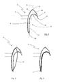
- a buoyancy profile side 9 and a resistance profile side 10 on both sides of the profile nose 8, that is lying opposite and separated by the profile nose 8 is in Fig. 4 an exemplary profile cross-section of a pure lift rotor 13 (NACA profile) in registration with the profile cross-section 6 according to the invention (FIG. Fig. 3 ).
- the profile of the lift rotor 13 is not part of the rotor blade according to the invention, but only for the purpose of illustrating the formation of the buoyancy profile side 9 of the profile cross-section 6 according to the invention.
- the buoyancy profile side 9 has a convexly curved course, which corresponds to one of the profile sides of the buoyancy runner 13.
- a resistance profile side 10 is provided in the rotor blade according to the invention.
- FIG Fig. 5 The profile cross section 6 of the rotor blade 2 according to the invention with a resistance profile side 10 is shown in FIG Fig. 5 represented at the same time with a profile cross section of a pure resistance rotor 14.
- the resistance rotor 14 is conventionally made as shown from a sheet whose free end is bent into a blade.
- the representation according to Fig. 5 illustrates the formation of the resistance profile side 10 in the profile cross-section 6 of the rotor blade 2 according to the invention with a contact characteristic of a conventional resistance rotor fourteenth
- the profile cross-section 6 of the rotor blade 2 is a closed hollow chamber profile, the buoyancy profile side 9 and the resistance profile side 10 being brought together at the profile nose 8 and a profile trailing edge 15.
- the closed hollow chamber profile has a low weight by the inclusion of a hollow chamber 16 through a continuous wall with low wall thicknesses and yet has a high rigidity, in particular a high torsional stiffness, so that the rotor blade 2 the mechanical loads occurring at high speeds despite low weight withstand. For torsional stiffness of the rotor blade 2 also contributes the profile nose 8 at.
- hollow chamber profile webs are provided in an embodiment, not shown, which connect and support substantially transversely to the direction of movement 7, the opposite wall portions of the hollow chamber profile.
- Such a profile cross section can be produced in the extrusion process.
- the rotor blade 2 with a hollow chamber profile is composed of several shell parts, which are easy to manufacture in each case.
- the rotor blade is advantageously made of aluminum sheet or other metal sheets, in particular light metals.
- the rotor blade is a component of fiber-reinforced plastic, in particular glass fiber reinforced plastic (GRP) or carbon fiber reinforced plastic (GRP), or consists of several fiber-reinforced plastic components.
- a maximum resistance surface with a corresponding width of the blade 11 and the blade channel 12 is formed by a subsequent to the blade 11 base wall 17 of the resistance profile side 12 is on the same side of a chord 18 as the buoyancy profile page 9.
- the chord profile 18th is determined by the profile nose 8 and the profile trailing edge 15.
- the position of the base wall 17 on one of the lift profile side facing side of the chord 18 is particularly advantageous in the design of the rotor blade 2 as a hollow chamber profile, since the hollow chamber profile with low weight large profile depths can be selected while the position of the base side 17 as wide as possible blade channel 12th limited.
- the profile cross-section 6 is formed in a convex surface portion 19 between the profile nose 8 and an outer blade edge 20 of the blade 11 as a buoyancy profile.
- the convex surface portion 19 cooperates aerodynamically with the lift profile side 9 and contributes to the acceleration of the rotor blade 2 at.
- the aerodynamically favorable convex course of the surface immediately adjacent to the blade edge 20 further reduces turbulence due to the blade edge 20 and increases the efficiency of the rotor blade second
- Fig.1 and Fig. 2 is the buoyancy profile side 9 of the axis of rotation 5 of the vertical wind turbine 1 facing.
- alternating sequences of rotor blades with the axis of rotation 5 facing buoyancy profile sides 9 and such rotor blades are provided, in which the buoyancy profile side with respect to the axis of rotation 5 is outside.
- the buoyancy profile sides of all rotor blades are arranged on the profile side of the profile cross-section 6 lying outside on the axis of rotation 5.
- the rotor blade 2 Due to the design of the rotor blade 2 as a combination of resistance rotor and buoyancy rotor can be achieved with the rotor blade according to the invention initially a significantly lower startup speed of the vertical wind turbine 1, as is possible with buoyancy runners. Furthermore, the advantages of fast-running wing profiles are used, especially at higher speeds, which are not achievable with pure resistance rotors.
- the inventive combination of resistance rotor and buoyancy rotor is realized on individual rotor blades 2, so that the advantages of this combination with low material costs and thus low total weight of the vertical wind turbine 1 are used in favor of an improved performance map of the vertical wind turbine 1.
- the buoyancy profile side 9 is impinged independently of the resistance profile side 10 so that dynamic buoyancy forces act on the rotor blade, since the resistance profile side 10 lies on the other side of the profile nose 8 as the buoyancy profile side 9.
- the resistance profile side 10 can therefore hinder the free flow of the buoyancy profile side 9 by the wind or the more influent with increasing speed wind in no rotor position, so that the vertical wind turbine 1 can accelerate.
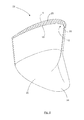
- a fin 22 is arranged in each case, which extends in the direction of the resistance profile side 10 bent.
- the fin 22 has on its side facing the rotor blade 2 base 23 to the profile cross-section of the rotor blade 2 and is tapered to its opposite, free end to a tongue 24.
- the fin 22 acts aerodynamically similar to a tail in aircraft and increases the coefficient of performance of the vertical wind turbine 1, since less drag resistance and turbulence arise at the trailing edges of the rotor blade 2. Further, the noise 22 of the vertical wind turbine 1 is reduced by the fins 22.
- the fin 22 also closes the hollow chamber 16 of the closed profile cross-section 6, whereby the efficiency of the rotor blade 2 is increased.
- the surface of the fin 22 is spherically formed on the side which adjoins the buoyancy profile side 9 of the rotor blade 2 and thereby promotes the buoyancy-generating properties of the rotor blade 2.
- the fin 22 continues one of the buoyancy profile side 9 associated section of the profile cross section 6 and covers the resistance profile side 10 to form an opening to the blade channel 12.
- the tongue 24 forms a chute 25 through the dirt, rainwater or a snow column discharged from the blade channel 12 become.
- the fin 22 is a component which can be inserted into the hollow chamber 16 of the rotor blade 2.
- the fin 22 may be made with a paragraph, so that the surface of the fin 22 is aligned with the surface of the rotor blade 2 after insertion into the hollow chamber 16.
- the fin 22 is butt-mounted to the free end of the rotor blade 2.
- the Fin 22 made of a glass or carbon fiber reinforced plastic. It may be partially formed as a hollow chamber profile, whereby further weight and material of the vertical wind turbine 1 can be saved.
- the fin 22 is formed integrally with the rotor blade 2 in a further advantageous embodiment.
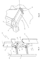
- Fig. 9 shows a further embodiment of a vertical wind turbine 30, which in contrast to the embodiment according to Fig. 1 and Fig. 2 has three vertically arranged rotor blades 31.
- the rotor blades 31 are each similar to a profile cross section 32 of the above with reference to FIG. 3 to FIG. 5 designed profile configuration designed.
- the profile cross section 31 of each rotor blade 31 in this case has a profile nose 8 arranged in advance in the direction of movement 7 and two profile sides on both sides of the profile nose 8.
- one of the profile sides is designed as a lift profile side 9 with an airfoil profile in the manner of a lift rotor and the other of the profile sides as a resistance profile side 10 with a counter to the direction of movement 7 of the rotor blade 2 open blade 11 in the manner of a resistance rotor.
- the rotor blades 31 are configured as solid profiles.
- the rotor blades 31 are advantageously components made of fiber-reinforced plastic, in particular glass fiber reinforced plastic (GRP) or carbon fiber reinforced plastic (GRP).
- GRP glass fiber reinforced plastic
- GRP carbon fiber reinforced plastic
- the rotor blades 31 of the vertical wind turbine according to Fig. 9 as hollow chamber profiles according to the Fig. 1 and Fig. 2 configured configuration configured.
- the free ends of the rotor blades 31 are in an embodiment, not shown, with fins 22 (FIG. Fig. 6 ) according to the embodiment according to Fig. 1 and Fig. 2 Mistake.
- the fins 22 are attached to the free ends of the rotor blade 31 with solid profile.
- the fins 22 are advantageously designed as an insertion part.
- the rotor blades 31 are held on radial struts 33 which hold the rotor blades 31 at the intended radial distance from the axis of rotation of the rotor.
- the struts 33 each hold at their radially outer ends a rotor blade and are mounted at their inner ends to a rotor ring 34 which rotates in the installation position of the rotor about the axis of rotation.
- the radial struts 33 are formed with a profile cross section 35 similar to the profile cross section 32 of the rotor blades 31.
- a similar profile cross section 35 is understood to mean that the profile cross section 35 of the radial struts 33 has the characteristic of the profile configuration according to the invention with a resistance profile side and a lift profile side.
- Each strut 33 comprises a profile nose 8 arranged in advance in the direction of movement 7 and two profile sides opposite the profile nose 8.
- One of the profile sides is designed as a lift profile side 9 with an airfoil profile in the manner of a lift rotor and the other of the profile sides as a resistance profile side 10.
Landscapes
- Engineering & Computer Science (AREA)
- Life Sciences & Earth Sciences (AREA)
- Sustainable Development (AREA)
- Sustainable Energy (AREA)
- Chemical & Material Sciences (AREA)
- Combustion & Propulsion (AREA)
- Mechanical Engineering (AREA)
- General Engineering & Computer Science (AREA)
- Physics & Mathematics (AREA)
- Fluid Mechanics (AREA)
- Wind Motors (AREA)
Abstract
Description
Die Erfindung betrifft ein Rotorblatt für eine Vertikalwindturbine gemäß Anspruch 1. Die Erfindung betrifft außerdem eine Vertikalwindturbine mit einem solchen Rotorblatt gemäß Anspruch 9.The invention relates to a rotor blade for a vertical wind turbine according to
Vertikalwindturbinen weisen einen Rotor auf, dessen Rotationsachse senkrecht zum Boden steht. Die Drehbewegung der Vertikalwindturbine ist dabei unabhängig von der Windrichtung, wodurch die Vertikalwindturbine im Vergleich zu Bauarten einer Windturbine mit horizontaler Rotationsachse unempfindlich gegen wechselnde Windrichtungen und wechselnde Windstärken ist. Die Bauart der Vertikalwindturbine wird insbesondere im unteren und mittleren Leistungsbereich von Windkraftanlagen gewählt, da sie einen robusten Aufbau aufweist und angeschlossene Komponenten wie Getriebe oder Generatoren leicht zugänglich in Bodennähe angeordnet werden können.Vertical wind turbines have a rotor whose axis of rotation is perpendicular to the ground. The rotary motion of the vertical wind turbine is independent of the wind direction, whereby the vertical wind turbine is insensitive to changing wind directions and changing wind speeds compared to types of a wind turbine with a horizontal axis of rotation. The design of the vertical wind turbine is chosen in particular in the lower and medium power range of wind turbines, since it has a robust construction and connected components such as gearboxes or generators can be easily accessible located near the ground.
Zur Generierung der für die nutzbare Drehbewegung um die Rotationsachse erforderlichen Kräfte weist eine Vertikalwindturbine Antriebselemente auf, welche die Funktionsweise der Vertikalwindturbine als Widerstandsläufer oder als Auftriebsläufer maßgeblich bestimmen.In order to generate the forces required for the usable rotational movement about the axis of rotation, a vertical wind turbine has drive elements which decisively determine the mode of operation of the vertical wind turbine as a resistance runner or as a lift runner.
Bei einer als Widerstandsläufer konzipierten Windturbine wird der Strömungswiderstand der Antriebselemente genutzt. Durch den Staudruck, der aufgrund des Abbremsens der Luftströmung auf der dem Wind zugewandten Luvseite des Antriebselements entsteht, wirkt auf das Antriebselement eine Kraft in der Lee-Richtung, welche durch entsprechende Anordnung des Antriebselements als Drehbewegung um die Rotationsachse umgesetzt wird. Ein bekannter Widerstandsläufer ist der Savonius-Rotor, bei dem als Antriebselemente zwei gegeneinander versetzt angeordnete Schaufeln vorgesehen sind.In a designed as resistance rotor wind turbine, the flow resistance of the drive elements is used. Due to the dynamic pressure, which arises due to the deceleration of the air flow on the windward windward side of the drive element acts on the drive element, a force in the leeward direction, which is implemented by appropriate arrangement of the drive element as a rotational movement about the axis of rotation. A known resistance rotor is the Savonius rotor, in which two mutually staggered blades are provided as drive elements.
Widerstandsläufer weisen ein hohes Drehmoment aus dem Stand auf und sind schon bei geringen Windgeschwindigkeiten einsetzbar. Allerdings haben Widerstandläufer regelmäßig ein großes Gewicht und weisen zudem vergleichsweise kleine Leistungsbeiwerte auf.Resistance runners have a high level of torque and can be used even at low wind speeds. However, have Resistance runners regularly a large weight and also have comparatively small performance coefficients.
Demgegenüber nutzen Auftriebsläufer den dynamischen Auftriebseffekt, der bei der Umströmung profilierter Rotorblätter entsteht. Das Rotorblatt eines Auftriebsläufers weist einen Profilquerschnitt eines Tragflächenprofils (NACA) auf. Dabei ist eine in Bewegungsrichtung des Rotorblatts vorlaufend angeordneten Profilnase und zwei beiderseits der Profilnase gegenüber liegende Profilseiten vorgesehen, an denen die Luftströmung Auftriebskräfte erzeugt. Im Betrieb einer als Auftriebsläufer konzipierten Vertikalwindturbine überlagert sich der Wind mit der durch die Drehbewegung entstehenden Luftströmung, so dass immer Vortriebskräfte entstehen. Ein bekannter Auftriebsläufer unter den Vertikalwindturbinen ist der Darrieus-Rotor, bei dem die Rotorblätter am oberen Ende und am unteren Ende einer vertikalen Welle befestigt sind und bogenförmig nach außen ragen.In contrast, buoyancy runners use the dynamic buoyancy effect created by the flow around profiled rotor blades. The rotor blade of a lift rotor has a profile cross-section of an airfoil (NACA). In this case, a forwardly arranged in the direction of movement of the rotor blade nose and two sides of the profile nose opposite profile sides is provided, where the air flow produces buoyant forces. During operation of a vertical wind turbine designed as a lift rotor, the wind is superimposed with the air flow resulting from the rotary movement, so that propulsive forces always arise. One known uplift rotor among the vertical wind turbines is the Darrieus rotor in which the rotor blades are secured at the top and bottom of a vertical shaft and arcuately outwardly projecting.
Bei sehr geringen Rotationsgeschwindigkeiten und insbesondere im Stillstand einer als Auftriebsläufer konzipierten Vertikalwindturbine ist allerdings ohne die Vortriebskraft aufgrund des Fahrtwinds regelmäßig eine Anfahrhilfe erforderlich, sofern ein spätes Anlaufen nicht gewünscht ist.At very low rotational speeds and especially at a standstill designed as a lift rotor vertical wind turbine, however, a traction help is usually required without the propulsive force due to the wind, unless a late start is not desired.
Des Weiteren sind Hybridformen bekannt, welche die Vorteile von Widerstands- und Auftriebsläufer bei verschiedenen Windgeschwindigkeiten zu kombinieren versuchen. Im unteren Geschwindigkeitsbereich wirkt das hohe Drehmoment des Widerstandsläufers, so dass keine Starterhilfe erforderlich ist. Im oberen Geschwindigkeitsbereich soll das hohe Drehmoment des Auftriebsläufers genutzt werden. Hybridformen sind zwar flexibler einsetzbar, erreichen aber nicht so hohe Leistungen wie reine Auftriebsläufer.Furthermore, hybrid forms are known which attempt to combine the advantages of drag and lift runners at various wind speeds. In the lower speed range acts the high torque of the resistance rotor, so that no starter help is required. In the upper speed range, the high torque of the lift rotor should be used. Although hybrid forms are more flexible, they do not achieve as high a performance as pure lift runners.
Eine Kombination aus Savonius-Rotor und Darrieus-Rotor offenbart
Aus
Die bekannten Vertikalwindturbinen und deren Rotorblätter haben bei Ausbildung als Widerstandsläufer Vorteile bei geringen Windgeschwindigkeiten auf Kosten hohen Gewichts und geringer Leistungsbeiwerte und bei Ausbildung als Auftriebsläufer Vorteile bei hohen Windgeschwindigkeiten bei Schwächen im unteren Leistungsbereich. Die bekannten Hybridformen stellen regelmäßig keine zufrieden stellenden Kompromisse über das gesamte Leistungskennfeld bereit oder haben eine unverhältnismäßig aufwendige und damit teure, sowie außerdem meistens schwere Bauweise.The known vertical wind turbines and their rotor blades in training as resistance runner have advantages at low wind speeds at the expense of high weight and low power coefficients and training as buoyancy runner advantages at high wind speeds at weaknesses in the lower power range. The known hybrid forms regularly provide no satisfactory compromises over the entire performance map or have a disproportionately expensive and therefore expensive, and also usually heavy construction.
Der vorliegenden Erfindung liegt daher das Problem zugrunde, mit möglichst geringem Materialaufwand das Leistungskennfeld einer Vertikalwindturbine zu optimieren.The present invention is therefore based on the problem of optimizing the performance map of a vertical wind turbine with the lowest possible cost of materials.
Dieses Problem wird erfindungsgemäß durch ein Rotorblatt für Vertikalwindturbinen mit den Merkmalen des Anspruchs 1 gelöst. Das Problem wird ferner durch eine Vertikalwindturbine mit den Merkmalen des Anspruchs 9 gelöst.This problem is solved by a rotor blade for vertical wind turbines with the features of
Erfindungsgemäß ist ein Rotorblatt vorgesehen, dessen Profilquerschnitt eine in Bewegungsrichtung des Rotorblatts vorlaufende Profilnase und beiderseits der Profilnase gegenüberliegende Profilseiten aufweist, wie es bspw. bei reinen Auftriebsläufern bekannt ist, wobei eine der Profilseiten als Widerstandsprofilseite mit einer entgegen der Bewegungsrichtung des Rotorblatts offene Schaufel nach Art eines Widerstandsläufers ausgebildet ist. Eine Auftriebsprofilseite bildet die der Widerstandprofilseite gegenüberliegende und über die Profilnase im Profilquerschnitt angebundene Profilseite und ist mit einem Tragflächenprofil nach Art eines Auftriebsläufers ausgestaltet. Im Bereich der Auftriebsprofilseite ist daher die Oberfläche des Rotorblatts konvex gewölbt ausgebildet, so dass die Luftströmung an der Oberfläche aerodynamisch Kräfte erzeugt, welche zum Antrieb des Rotors genutzt werden können. Die Wölbung der Auftriebsprofilseite ist dabei derart ausgebildet, dass möglichst große aerodynamische Wirkung erzielt wird. Die Profilnase teilt dabei die Auftriebsprofilseite und die Widerstandsprofilseite, so dass diese Profilseiten im Profilquerschnitt des Rotorblatts gegenüber liegen.According to the invention, a rotor blade is provided whose profile cross-section has a profile nose leading in the direction of movement of the rotor blade and profile sides on both sides of the profile nose, as is known, for example, in pure lift rotors, one of the profile sides being a resistance profile side with a blade open against the direction of movement of the rotor blade according to Art a resistance rotor is formed. A buoyancy profile side forms the side opposite the resistance profile side and connected via the profile nose in the profile cross section profile side and is designed with a wing profile in the manner of a buoyancy rotor. In the area of the buoyancy profile side, therefore, the surface of the rotor blade is convexly curved, so that the air flow on the surface generates aerodynamic forces, which are used to drive the rotor can be used. The curvature of the lift profile side is designed such that the greatest possible aerodynamic effect is achieved. The profile nose divides the buoyancy profile side and the resistance profile side, so that these profile sides lie opposite each other in the profile cross section of the rotor blade.
Das erfindungsgemäße Rotorblatt erzeugt im Stillstand oder niedrigen Drehzahlen einer Vertikalwindturbine über seine Widerstandsprofilseite ein starkes Drehmoment, wenn die Schaufel der Widerstandsprofilseite den anströmenden Wind einfängt. Das Leistungskennfeld der erfindungsgemäßen Vertikalwindturbine weist daher im Bereich niedriger Drehzahlen ansprechende Leistungswerte auf. Mit höheren Windgeschwindigkeiten beschleunigt die Vertikalwindturbine aufgrund der Wirkung der Auftriebsprofilseite und verhält sich mit dem Anstieg der Drehzahlen zunehmend wie ein Auftriebsläufer.The rotor blade according to the invention generates at standstill or low speeds of a vertical wind turbine on its resistance profile side a strong torque when the blade of the resistance profile side captures the oncoming wind. The power map of the vertical wind turbine according to the invention therefore has attractive power values in the low-speed range. With higher wind speeds, the vertical wind turbine accelerates due to the effect of the lift profile side and behaves increasingly like a lift rotor with the increase of the speeds.
Aufgrund der Widerstandsprofilseite kann auf Windfahnen oder Rotorblattverstellungen, wie sie bei reinen Auftriebsläufern oft vorgesehen sind, verzichtet werden.Due to the resistance profile side, it is possible to dispense with wind vanes or rotor blade adjustments, which are often provided in pure lift runners.
Die erfindungsgemäße Vertikalwindturbine weist durch die Kombination von Widerstandsläufer und Auftriebsläufer an einem Rotorblatt und bei geringem Materialeinsatz einerseits eine niedrige Anlaufgeschwindigkeit auf und kann andererseits auch die Vorteile von schnell laufenden Tragflächenprofilen nutzen.The vertical wind turbine according to the invention has on the one hand by the combination of resistance rotor and buoyancy rotor on a rotor blade and low material usage on a low startup speed and on the other hand can also take advantage of fast-running airfoils.
Das erfindungsgemäße Rotorblatt kann nämlich mit geringem Materialeinsatz die Vorteile von Auftriebsläufern mit denen von Widerstandsläufern kombinieren und vermeidet weitgehend deren jeweilige Nachteile. Insbesondere ist einem Abbremsen des Rotors bei zunehmenden Drehzahlen, wie es für Widerstandsläufer typisch ist, durch die Anordnung einer der Schaufel der Widerstandprofilseite voraus laufenden Profilnase entgegen gewirkt. Der Widerstandsbeiwert des erfindungsgemäßen Profilquerschnitts wird nämlich durch die Profilnase effektiv gesenkt, wodurch auf das Rotorblatt nur geringe Windwiderstandskräfte wirken können. Die Auftriebsprofilseite wird unabhängig von der Widerstandsprofilseite angeströmt, so dass auf das Rotorblatt dynamische Auftriebskräfte wirken, da die Widerstandsprofilseite auf der anderen Seite der Profilnase als die Auftriebsprofilseite liegt. Die Widerstandsprofilseite kann daher in keiner Rotorstellung die freie Anströmung der Auftriebsprofilseite durch den Wind bzw. den mit zunehmender Drehzahl einflussreicheren Fahrtwind behindern, so dass die Vertikalwindturbine beschleunigen kann.The rotor blade according to the invention can namely combine the advantages of buoyancy runners with those of resistance runners with little use of material and largely avoids their respective disadvantages. In particular, braking of the rotor at increasing rotational speeds, as is typical for resistance rotors, is counteracted by the arrangement of one of the blades of the resistance profile side ahead of the profile nose. The drag coefficient of the profile cross section according to the invention is namely effectively lowered by the profile nose, which can act on the rotor blade only low wind resistance forces. The buoyancy profile side is impinged independently of the resistance profile side, so that dynamic buoyancy forces act on the rotor blade, since the resistance profile side lies on the other side of the profile nose as the buoyancy profile side. The Resistance profile side can therefore hinder in any position of the rotor, the free flow of the lift profile side by the wind or the more influential with increasing speed of wind, so that the vertical wind turbine can accelerate.
Die Profilnase teilt im Betrieb der Vertikalwindturbine die anströmende Luftströmung, so dass die Auftriebsprofilseite optimal angeströmt wird und die Wirkung eines Auftriebsläufers verbessert zum Tragen bringen kann. Die Profilnase fördert zudem die Steifigkeit des Rotorblatts, insbesondere die Torsionssteifigkeit.The profile nose divides the incoming air flow during operation of the vertical wind turbine, so that the buoyancy profile side is optimally flown and can bring the effect of a buoyancy rotor improved to bear. The profile nose also promotes the rigidity of the rotor blade, in particular the torsional stiffness.
Eine Reduzierung des Gewichts des Rotorblatts ist durch eine Ausbildung des Profilquerschnitts als geschlossenes Hohlkammerprofil gegeben. Die Widerstandsprofilseite und die Auftriebsprofilseite sind dabei einerseits an der Profilnase und andererseits an einer Profilhinterkante zusammengeführt. Darunter ist eine funktionale Zusammenführung zu verstehen, welche nicht notwendig mit einer fertigungstechnischen Zusammenfügung von Bauteilen zusammenfallen muss. Das geschlossene Hohlkammerprofil kann jedoch auf einfache Weise durch Zusammenfügen einfach zu fertigender Blattschalen im Bereich der Profilnase und der Profilhinterkante hergestellt werden. In einer weiteren Ausführungsform sind Blattschalen zusätzlich oder alternativ im Bereich der Schaufel der Widerstandsprofilseite gefügt.A reduction of the weight of the rotor blade is given by a design of the profile cross section as a closed hollow chamber profile. The resistance profile side and the lift profile side are brought together on the one hand on the profile nose and on the other hand on a profile trailing edge. This is to be understood as a functional combination which does not necessarily have to coincide with a production-related assembly of components. However, the closed hollow chamber profile can be produced in a simple manner by joining easy to be produced leaf shells in the profile nose and the profile trailing edge. In another embodiment, leaf shells are additionally or alternatively joined in the region of the blade of the resistance profile side.
Das Hohlkammerprofil weist eine hohe Steifigkeit auf und ermöglicht größere Dimensionen des Rotorblatts sowohl hinsichtlich Blattlänge als auch Profiltiefe, als es bei einfachen Blechprofilen oder auch Vollquerschnitten möglich wäre, da einfache Blechprofile nicht die nötige Steifigkeit bieten können und Vollquerschnitte bei größeren Dimensionen zu einem unerwünschten Anstieg des Gewichts führen.The hollow chamber profile has a high rigidity and allows larger dimensions of the rotor blade both in terms of blade length and tread depth, as it would be possible for simple sheet metal profiles or solid sections, since simple sheet metal profiles can not provide the necessary rigidity and solid sections with larger dimensions to an undesirable increase in Lead weight.
Die Schaufel der Widerstandsprofilseite begrenzt in einer vorteilhaften Ausführungsform der Erfindung einen runden Schaufelkanal, welcher sich über die Länge des Rotorblatts erstreckt. Der Schaufelkanal ist dabei ausgebildet, beispielsweise kreisrund oder mit homogen veränderten Rundungsradien, so dass keine Ecken gebildet sind, welche strömungsmechanisch ungünstig sind und zudem die Bildung von Ablagerung von Schmutzpartikeln begünstigen, welche mit dem Wind in den Schaufelkanal gelangen können. Auch Wasser oder Schnee können leichter aus dem Schaufelkanal abgeführt werden.The blade of the resistance profile side limits in an advantageous embodiment of the invention a round blade channel, which extends over the length of the rotor blade. The blade channel is formed, for example, circular or with homogeneously changed rounding radii, so that no corners are formed, which are unfavorable fluid mechanics and also favor the formation of deposits of dirt particles, which with the wind in the Can reach shovel channel. Even water or snow can be easily removed from the blade channel.
Vorteilhaft ist der Profilquerschnitt in einem Abschnitt zwischen der Profilnase und einer außen liegenden Schaufelkante der Schaufel als Auftriebsprofil ausgebildet, wodurch dieser Abschnitt der Widerstandprofilseite, der auf die Wirksamkeit des Profils als Widerstandsläufer wenig Einfluss hat, zur Generierung zusätzlicher Auftriebskräfte mit der anströmenden Luft genutzt wird. Diese zusätzlichen Auftriebskräfte ergänzen die Auftriebskräfte der Auftriebsprofilseite.Advantageously, the profile cross section is formed in a section between the profile nose and an outer blade edge of the blade as buoyancy profile, whereby this portion of the resistance profile side, which has little effect on the effectiveness of the profile as a resistance rotor, is used to generate additional buoyancy forces with the incoming air. These additional buoyancy forces complement the buoyancy forces of the buoyancy profile side.
In einer vorteilhaften Ausführungsform liegt eine an die Schaufel angeschlossene Grundwand der Widerstandsprofilseite auf der gleichen Seite einer durch die Profilnase und die Profilhinterkante bestimmten Profilsehne wie die Auftriebsprofilseite. Dadurch kann bei einer gegebenen Profiltiefe einerseits auf der Widerstandsprofilseite eine größtmögliche Widerstandfläche mit einer entsprechenden Breite der Schaufel bzw. des Schaufelkanals ausgebildet werden und andererseits auf der Auftriebsprofilseite zusätzliche Freiheitsgrade zur Gestaltung des Tragflächenprofils gegeben werden, um ein gewünschtes strömungsmechanisches Verhalten des Rotorblatts mit einer entsprechenden Profilierung der Auftriebsprofilseite umzusetzen.In an advantageous embodiment, a base wall of the resistance profile side connected to the blade lies on the same side of a profile chord as the lift profile side determined by the profile nose and the profile trailing edge. As a result, at a given tread depth on the resistance profile side, a maximum resistance surface with a corresponding width of the blade or of the blade channel can be formed and, on the other hand, additional degrees of freedom for shaping the airfoil profile can be given on the lift profile side in order to achieve a desired flow-mechanical behavior of the rotor blade with a corresponding profiling the lift profile side implement.
In bevorzugter Ausgestaltung der Erfindung liegt die Auftriebsprofilseite der Rotationsachse zugewandt, wodurch die außen liegende Widerstandsprofilseite mit ihrer entsprechend radial nach außen greifenden Schaufel ein höheres Drehmoment um die Rotationsachse erzeugt.In a preferred embodiment of the invention, the buoyancy profile side facing the axis of rotation, whereby the outer resistance profile side generates with its corresponding radially outwardly reaching blade a higher torque around the axis of rotation.
Ist an den freien Enden des Rotorblatts jeweils eine Finne angeordnet, so wird der Leistungsbeiwert der Vertikalwindturbine signifikant erhöht, da an den Abrisskanten der als Auftriebsläufer wirkenden Komponenten des Rotorblatts weniger Strömungswiderstände und Verwirbelungen entstehen. Dadurch wird auch die Geräuschemission der Vertikalwindturbine verringert. Unter einer Finne wird dabei ein Element verstanden, welches mit dem Rotorblatt und insbesondere der dynamisch wirkenden Auftriebsprofilseite fluchtet und ähnlich dem Leitwerk bei Flugzeugen oder Flossen bei Fischen wirkt. Die Finne ist zu diesem Zweck zu ihrem Ende zunehmend flacher ähnlich einer Zunge ausgebildet. Die Finne verschließt dabei die Hohlkammer des Profilquerschnitts, wodurch der Wirkungsgrad des Rotorblatts verbessert ist.If in each case a fin is arranged at the free ends of the rotor blade, the power coefficient of the vertical wind turbine is significantly increased, since fewer drag resistances and turbulences arise at the demolition edges of the components of the rotor blade acting as lift skid. As a result, the noise emission of the vertical wind turbine is reduced. A fin is understood to mean an element which is aligned with the rotor blade and in particular the dynamically acting lift profile side and acts similarly to the tail unit in aircraft or fins in fish. The Finn is to this end increasingly flatter similar to one end Tongue formed. The fin closes the hollow chamber of the profile cross-section, whereby the efficiency of the rotor blade is improved.
Vorteilhaft verläuft die Finne in Richtung der Widerstandsprofilseite gebogen oder winkelig angestellt, wodurch eine Rutsche gebildet ist, über die Schmutz, Regenwasser oder auch eine Schneesäule aus dem Schaufelkanal abgeführt werden. Aufgrund der vertikalen Anordnung des Rotorblatts gleiten selbst Eisschichten, welche sich während des Stillstands der Vertikalwindturbine im Schaufelkanal bei entsprechenden Witterungsbedingungen bilden können aufgrund ihres Eigengewichts durch die Rutsche der Finne ab. Der Radius der Biegung bzw. der Anstellwinkel der Finne wird unter Berücksichtigung der gewünschten aerodynamischen Eigenschaften der Finne und des mit der Finne ausgestatteten Rotorblatts einerseits und der Rutsche der Finne andererseits bestimmt.Advantageously, the fin extends bent or angled in the direction of the resistance profile side, whereby a chute is formed, are discharged through the dirt, rainwater or a snow column from the blade channel. Due to the vertical arrangement of the rotor blade even ice layers, which can form during standstill of the vertical wind turbine in the blade channel in appropriate weather conditions due to their own weight slide through the chute of the fin. The radius of the bend or the angle of attack of the fin is determined taking into account the desired aerodynamic properties of the fin and of the fin-equipped rotor blade on the one hand and the chute of the fin on the other hand.
Setzt die Finne einen der Auftriebsprofilseite zugeordneten Abschnitt des Profilquerschnitts fort und überdeckt die Widerstandsprofilseite unter Ausbildung einer Öffnung zum Schaufelkanal, so ist ein axialer Abschluss des Schaufelkanals gegeben, welcher den Leistungsbeiwert des Rotorblatts bzw. der Vertikalwindturbine erhöht, unter gleichzeitiger Bereitstellung einer Rutsche zur Abführung von Wasser- oder Eisfracht aus dem Schaufelkanal gegeben.If the fin continues a section of the profile cross-section associated with the lift profile side and covers the drag profile side to form an opening to the blade channel, there is axial termination of the blade channel, which increases the power coefficient of the rotor blade or vertical wind turbine, while simultaneously providing a chute for discharging Water or ice freight from the blade channel given.
Die Finne ist in einer vorteilhaften Ausgestaltung ein in die Hohlkammer einschiebbares Bauteil. Sie besteht in einer vorteilhaften Ausführung aus einem glas- oder kohlefaserverstärkten Kunststoff. In einer weiteren vorteilhaften Ausführungsform ist die Finne einstückig mit dem Rotorblatt bzw. einstückig mit den Komponenten des Rotorblatts ausgebildet, aus denen das Rotorblatt mit seinem geschlossenen Hohlkammerprofil zusammengesetzt ist.The fin is in an advantageous embodiment, a retractable into the hollow chamber component. It consists in an advantageous embodiment of a glass or carbon fiber reinforced plastic. In a further advantageous embodiment, the fin is formed integrally with the rotor blade or integrally with the components of the rotor blade, from which the rotor blade is assembled with its closed hollow chamber profile.
Bei einer erfindungsgemäßen Vertikalwindturbine werden die Rotorblätter bevorzugt parallel zur Rotationsachse, das heißt senkrecht zum Boden, angeordnet. Dadurch wird der Materialeinsatz bei höherem Leistungsbeiwert für die wirksame Fläche im Vergleich zu anderen Anordnungen verringert. Zudem ist sichergestellt, dass sich alle Bereiche des erfindungsgemäßen Rotorblatts gleich schnell bewegen, was sowohl für die Wirksamkeit der Widerstandsprofilseite als auch der Auftriebsprofilseite vorteilhaft ist. Die Rotorblätter können mit einheitlichem Anstellwinkel im Hinblick auf die Auftriebsprofilsseite an dem Rotor der Vertikalwindturbine befestigt werden.In a vertical wind turbine according to the invention, the rotor blades are preferably arranged parallel to the axis of rotation, that is perpendicular to the ground. This reduces the use of material with a higher coefficient of performance for the effective area compared to other arrangements. In addition, it is ensured that all areas of the rotor blade according to the invention move at the same speed, which is advantageous both for the effectiveness of the resistance profile side and the lift profile side. The Rotor blades can be fixed at a uniform angle of attack with respect to the lift profile side on the rotor of the vertical wind turbine.
Die Rotorblätter der erfindungsgemäßen Vertikalwindturbine sind an radialen Streben gehalten. Unter einer radialen Strebe ist dabei ein längliches Bauteil zu verstehen, welches in seiner Einbaulage an seinem Ende, welches das Rotorblatt trägt, in einem Abstand zur Rotationsachse des Rotors liegt. Die Ausrichtung der Strebe hat demnach wenigstens eine radiale Komponente oder ist ausschließlich radial.The rotor blades of the vertical wind turbine according to the invention are held on radial struts. Under a radial strut is an elongate member to understand, which is in its installed position at its end, which carries the rotor blade, at a distance from the axis of rotation of the rotor. The orientation of the strut therefore has at least one radial component or is exclusively radial.
In einer vorteilhaften Weiterbildung der Erfindung sind die radialen Streben mit einem Profilquerschnitt ähnlich dem erfindungsgemäßen Rotorblatt ausgebildet. Die Streben weisen demnach ähnlich den Rotorblättern einen Profilquerschnitt mit einer in Bewegungsrichtung des Rotors vorlaufend angeordneten Profilnase und zwei beiderseits der Profilnase gegenüber liegenden Profilseiten auf. Dabei ist eine der Profilseiten als Auftriebsprofilseite mit einem Tragflächenprofil nach Art eines Auftriebsläufers und die andere der Profilseiten als Widerstandsprofilseite mit einer entgegen der Bewegungsrichtung des Rotors offenen Schaufel nach Art eines Widerstandsläufers ausgebildet ist. Die erfindungsgemäß als Profil gestalteten Streben verstärken die vorteilhaften Wirkungen der Vertikalwindturbine mit der erfindungsgemäßen Kombination von Widerstandsläufer und Auftriebsläufer.In an advantageous embodiment of the invention, the radial struts are formed with a profile cross-section similar to the rotor blade according to the invention. Accordingly, the struts have, similar to the rotor blades, a profile cross-section with a profile nose arranged in advance in the direction of movement of the rotor and two profile sides on both sides of the profile nose. In this case, one of the profile sides is designed as a lift profile side with an airfoil profile in the manner of a lift rotor and the other of the profile sides as a resistance profile side with a counter to the direction of movement of the rotor open blade in the manner of a resistance rotor. The inventively designed as a profile struts enhance the beneficial effects of the vertical wind turbine with the combination of resistance rotor and buoyancy rotor according to the invention.
Weitere Merkmale der Erfindung ergeben sich aus den Unteransprüchen und den Ausführungsbeispielen, welche nachstehend anhand der Zeichnung näher erläutert sind. Es zeigen:
- Fig. 1
- eine modellhafte Ansicht eines Ausführungsbeispiels einer Vertikalwindturbine,
- Fig. 2
- eine Draufsicht auf die Vertikalwindturbine gemäß
Fig. 1 , - Fig. 3
- einen Profilquerschnitt eines Rotorblatts,
- Fig. 4
- den Profilquerschnitt gemäß
Fig. 3 mit Hervorhebung der Auftriebsprofilseite, - Fig. 5
- den Profilquerschnitt gemäß
Fig. 3 mit Hervorhebung der Widerstandsprofilseite, - Fig. 6
- eine perspektivische Ansicht einer Finne eines Rotorblatts,
- Fig. 7
- eine Frontansicht der Finne gemäß
Fig. 6 , - Fig. 8
- eine Hinteransicht der Finne gemäß
Fig. 6 , - Fig. 9
- eine perspektivische Ansicht eines weiteren Ausführungsbeispiels einer Vertikalwindturbine,
- Fig. 10
- eine Vergrößerung des Ausschnitts IX in
Fig. 9 .
- Fig. 1
- a model view of an embodiment of a vertical wind turbine,
- Fig. 2
- a plan view of the vertical wind turbine according to
Fig. 1 . - Fig. 3
- a profile cross-section of a rotor blade,
- Fig. 4
- the profile cross-section according to
Fig. 3 highlighting the lift profile side, - Fig. 5
- the profile cross-section according to
Fig. 3 highlighting the resistance profile page, - Fig. 6
- a perspective view of a fin of a rotor blade,
- Fig. 7
- a front view of the fin according to
Fig. 6 . - Fig. 8
- a rear view of the fin according to
Fig. 6 . - Fig. 9
- a perspective view of another embodiment of a vertical wind turbine,
- Fig. 10
- an enlargement of the section IX in
Fig. 9 ,
In der nachfolgenden Figurenbeschreibung sind für jeweils gleiche Bauteile die gleichen Bezugszeichen verwendet.In the following description of the figures, the same reference numerals are used for the same components.
Die Rotorblätter 2 sind symmetrisch, das heißt in gleichen Winkelabständen zueinander angeordnet. Die Rotorblätter 2 weisen einen nachstehend näher beschriebenen Profilquerschnitt 6 auf. Der Profilquerschnitt 6 bewirkt dabei, dass anströmende Luft an den Rotorblättern 2 Kräfte generiert, deren vektorielle Summe ein resultierendes Drehmoment um die Rotationsachse 5 erzeugt, so dass der Rotor 4 in einer Bewegungsrichtung 7 angetrieben wird.The
Im gezeigten Ausführungsbeispiel sind alle Rotorblätter 2 mit dem gleichen Profilquerschnitt 6 gestaltet. In weiteren vorteilhaften Ausführungsbeispielen sind einige der am Umfang des Rotors 4 angeordneten Rotorblätter mit dem nachstehend beschriebenen erfindungsgemäßen Profilquerschnitt 6 ausgestaltet. Die erfindungsgemäßen Rotorblätter 2 sind dabei vorteilhaft in gleichen Abständen am Umfang des Rotors 4 angeordnet, wobei zwischen den erfindungsgemäßen Rotorblättern 2 solche Rotorblätter mit anderen Profilquerschnitten angeordnet sind.In the illustrated embodiment, all
Der Profilquerschnitt 6 des Rotorblatts 2, welcher in
Das Rotorblatt 2 erzeugt im Stillstand oder niedrigen Drehzahlen der Vertikalwindturbine 1 über die Widerstandsprofilseite 10 ein starkes Drehmoment, wenn die Schaufel 11 den anströmenden Wind einfängt. Mit höheren Windgeschwindigkeiten setzt zunehmend die Wirkung der Auftriebsprofilseite 9 des Rotorblatts 2 ein. Die Vertikalwindturbine 1 verhält sich mit dem Anstieg der Drehzahlen zunehmend wie ein Auftriebsläufer und beschleunigt, so dass hohe Leistungsbeiwerte erreicht werden.The
Zur Veranschaulichung der erfindungsgemäßen Anordnung einer Auftriebsprofilseite 9 und einer Widerstandsprofilseite 10 beiderseits der Profilnase 8, das heißt gegenüber liegend und durch die Profilnase 8 getrennt, ist in
Der Profilquerschnitt 6 des erfindungsgemäßen Rotorblatts 2 mit einer Widerstandsprofilseite 10 ist in
Der Profilquerschnitt 6 des erfindungsgemäßen Rotorblatts 2 ist ein geschlossenes Hohlkammerprofil, wobei die Auftriebsprofilseite 9 und die Widerstandsprofilseite 10 an der Profilnase 8 und einer Profilhinterkante 15 zusammengeführt sind. Das geschlossene Hohlkammerprofil hat durch den Einschluss einer Hohlkammer 16 durch eine durchlaufende Wand bei geringen Wandstärken ein geringes Gewicht und weist dabei dennoch eine hohe Steifigkeit, insbesondere eine hohe Torsionssteifigkeit, auf, so dass das Rotorblatt 2 den bei hohen Drehzahlen auftretenden mechanischen Belastungen trotz geringen Gewichts standhält. Zur Torsionssteifigkeit des Rotorblatts 2 trägt ferner die Profilnase 8 bei.The
Zur weiteren Versteifung des Hohlkammerprofils sind in einem nicht gezeigten Ausführungsbeispiel Stege vorgesehen, welche im Wesentlichen quer zur Bewegungsrichtung 7 die gegenüberliegenden Wandabschnitte des Hohlkammerprofils verbinden und abstützen. Ein derartiger Profilquerschnitt ist im Strangpressverfahren herstellbar.For further stiffening of the hollow chamber profile webs are provided in an embodiment, not shown, which connect and support substantially transversely to the direction of
Das Rotorblatt 2 mit Hohlkammerprofil ist aus mehreren Schalenteilen zusammengesetzt, welche jeweils für sich einfach zu fertigen sind. Vorteilhaft wird das Rotorblatt aus Aluminiumblech oder anderen Metallblechen, insbesondere Leichtmetallen, gefertigt. In weiteren Ausführungsbeispielen ist das Rotorblatt ein Bauteil aus faserverstärktem Kunststoff, insbesondere glasfaserverstärktem Kunststoff (GFK) oder kohlefaserverstärktem Kunststoff (GFK), oder besteht aus mehreren faserverstärkten Kunststoffbauteilen.The
Auf der Widerstandsprofilseite 10 ist eine größtmögliche Widerstandfläche mit einer entsprechenden Breite der Schaufel 11 bzw. des Schaufelkanals 12 ausgebildet, indem eine an die Schaufel 11 anschließende Grundwand 17 der Widerstandsprofilseite 12 auf der gleichen Seite einer Profilsehne 18 liegt wie die Auftriebsprofilseite 9. Die Profilsehne 18 ist dabei durch die Profilnase 8 und die Profilhinterkante 15 bestimmt. Die Lage der Grundwand 17 auf einer der Auftriebsprofilseite zugewandten Seite der Profilsehne 18 ist bei der Gestaltung des Rotorblatts 2 als Hohlkammerprofil besonders vorteilhaft, da mit dem Hohlkammerprofil bei geringem Gewicht große Profiltiefen gewählt werden können und dabei die Lage der Grundseite 17 einen möglichst breiten Schaufelkanal 12 begrenzt. Durch die Lage der Grundwand 17 innerhalb des Hohlkammerprofils sind ferner auf der Auftriebsprofilseite zusätzliche Freiheitsgrade zur Gestaltung des Tragflächenprofils gegeben, um durch entsprechende Formgebung des Tragflächenprofils auf der Auftriebsprofilseite ein bestimmtes strömungsmechanisches Verhalten für ein gewünschtes Leistungskennfeld der Vertikalwindturbine 1 umzusetzen.On the
Der Profilquerschnitt 6 ist in einem konvexen Oberflächenabschnitt 19 zwischen der Profilnase 8 und einer außen liegenden Schaufelkante 20 der Schaufel 11 als Auftriebsprofil ausgebildet. Der konvexe Oberflächenabschnitt 19 wirkt aerodynamisch mit der Auftriebsprofilseite 9 zusammen und trägt zur Beschleunigung des Rotorblatts 2 bei. Der aerodynamisch günstige konvexe Verlauf der Oberfläche unmittelbar neben der Schaufelkante 20 verringert ferner Verwirbelungen aufgrund der Schaufelkante 20 und erhöht den Wirkungsgrad des Rotorblatts 2.The
Im gezeigten Ausführungsbeispiel gemäß
Durch die Ausbildung des Rotorblatts 2 als Kombination von Widerstandsläufer und Auftriebsläufer können mit dem erfindungsgemäßen Rotorblatt zunächst eine erheblich niedrigere Anlaufgeschwindigkeit der Vertikalwindturbine 1 erreicht werden, als mit Auftriebsläufern möglich ist. Ferner werden auch die Vorteile von schnell laufenden Tragflächenprofilen genutzt, insbesondere bei höheren Drehzahlen, welche mit reinen Widerstandsläufern nicht erreichbar sind. Die erfindungsgemäße Kombination von Widerstandsläufer und Auftriebsläufer ist an einzelnen Rotorblättern 2 realisiert, so dass die Vorteile dieser Kombination mit geringem Materialaufwand und damit geringem Gesamtgewicht der Vertikalwindturbine 1 zugunsten eines verbesserten Leistungskennfelds der Vertikalwindturbine 1 genutzt werden.Due to the design of the
Die Auftriebsprofilseite 9 wird unabhängig von der Widerstandsprofilseite 10 angeströmt, so dass auf das Rotorblatt dynamische Auftriebskräfte wirken, da die Widerstandsprofilseite 10 auf der anderen Seite der Profilnase 8 als die Auftriebsprofilseite 9 liegt. Die Widerstandsprofilseite 10 kann daher in keiner Rotorstellung die freie Anströmung der Auftriebsprofilseite 9 durch den Wind bzw. den mit zunehmender Drehzahl einflussreicheren Fahrtwind behindern, so dass die Vertikalwindturbine 1 beschleunigen kann.The
An den freien Enden 21 jedes Profilblatts 2 ist jeweils eine Finne 22 angeordnet, welche in Richtung der Widerstandsprofilseite 10 gebogen verläuft. Die Finne 22 weist an ihrer dem Rotorblatt 2 zugewandten Grundseite 23 den Profilquerschnitt des Rotorblatts 2 auf und ist zu ihrem gegenüberliegenden, freien Ende zu einer Zunge 24 verjüngt. Die Finne 22 wirkt aerodynamisch ähnlich einem Leitwerk bei Flugzeugen und erhöht den Leistungsbeiwert der Vertikalwindturbine 1, da an den Abrisskanten des Rotorblatts 2 weniger Strömungswiderstände und Verwirbelungen entstehen. Ferner wird durch die Finnen 22 die Geräuschemission der Vertikalwindturbine 1 verringert. Die Finne 22 verschließt zudem die Hohlkammer 16 des geschlossenen Profilquerschnitts 6, wodurch der Wirkungsgrad des Rotorblatts 2 erhöht ist.At the free ends 21 of each
Die Oberfläche der Finne 22 ist auf der Seite, welche an die Auftriebsprofilseite 9 des Rotorblatts 2 anschließt, sphärisch ausgebildet und fördert dadurch die Auftrieb erzeugenden Eigenschaften des Rotorblatts 2.The surface of the
Die Finne 22 setzt einen der Auftriebsprofilseite 9 zugeordneten Abschnitt des Profilquerschnitts 6 fort und überdeckt die Widerstandsprofilseite 10 unter Ausbildung einer Öffnung zum Schaufelkanal 12. Dabei bildet die Zunge 24 eine Rutsche 25, über die Schmutz, Regenwasser oder auch eine Schneesäule aus dem Schaufelkanal 12 abgeführt werden.The
Die Finne 22 ist im gezeigten Ausführungsbeispiel ein in die Hohlkammer 16 des Rotorblatts 2 einschiebbares Bauteil. Die Finne 22 kann dabei mit einem Absatz gefertigt sein, so dass die Oberfläche der Finne 22 nach dem Einfügen in die Hohlkammer 16 mit der Oberfläche des Rotorblatts 2 fluchtet. In einem weiteren Ausführungsbeispiel ist die Finne 22 stumpf an dem freien Ende des Rotorblatts 2 befestigt. In einem vorteilhaften Ausführungsbeispiel besteht die Finne 22 aus einem glas- oder kohlefaserverstärkten Kunststoff. Sie kann abschnittsweise als Hohlkammerprofil ausgebildet sein, wodurch weiteres Gewicht und Material der Vertikalwindturbine 1 eingespart werden kann. Insbesondere bei Ausbildung der Finne 22 mit einer Hohlkammer ist die Finne 22 in einem weiteren vorteilhaften Ausführungsbeispiel einstückig mit dem Rotorblatt 2 ausgebildet.In the exemplary embodiment shown, the
Im Unterschied zum Ausführungsbeispiel gemäß
Die freien Enden der Rotorblätter 31 sind in einem nicht dargestellten Ausführungsbeispiel mit Finnen 22 (
Die Rotorblätter 31 sind an radialen Streben 33 gehalten, welche die Rotorblätter 31 in dem vorgesehenen radialen Abstand zur Rotationsachse des Rotors halten. Die Streben 33 halten jeweils an ihren radial außen liegenden Enden ein Rotorblatt und sind an ihren innen liegenden Enden an einem Rotorring 34 montiert, welcher in Einbaulage des Rotors um die Rotationsachse dreht.The
Die radialen Streben 33 sind mit einem Profilquerschnitt 35 ähnlich dem Profilquerschnitt 32 der Rotorblätter 31 ausgebildet. Unter einem ähnlichen Profilquerschnitt 35 ist dabei zu verstehen, dass der Profilquerschnitt 35 der radialen Streben 33 die Charakteristik der erfindungsgemäßen Profilkonfiguration mit einer Widerstandsprofilseite und einer Auftriebsprofilseite aufweist. Jede Strebe 33 umfasst eine in Bewegungsrichtung 7 vorlaufend angeordnete Profilnase 8 und zwei beiderseits der Profilnase 8 gegenüber liegende Profilseiten. Eine der Profilseiten ist dabei als Auftriebsprofilseite 9 mit einem Tragflächenprofil nach Art eines Auftriebsläufers und die andere der Profilseiten als Widerstandsprofilseite 10 ausgebildet.The radial struts 33 are formed with a profile cross section 35 similar to the
Claims (11)
dadurch gekennzeichnet, dass
die eine der Profilseiten als Auftriebsprofilseite (9) mit einem Tragflächenprofil nach Art eines Auftriebsläufers und die andere der Profilseiten als Widerstandsprofilseite (10) mit einer entgegen der Bewegungsrichtung (7) des Rotorblatts (2, 31) offenen Schaufel (11) nach Art eines Widerstandsläufers ausgebildet ist.Rotor blade (2, 31) for vertical wind turbines (1, 30) with a profile cross section (6, 32) which has a profile nose (8) arranged in advance in the direction of movement (7) of the rotor blade (2, 31) and two on both sides of the profile nose (8) has opposite profile pages,
characterized in that
one of the profile sides as buoyancy profile side (9) with a wing profile in the manner of a lift rotor and the other of the profile sides as resistance profile side (10) with an opposite to the direction of movement (7) of the rotor blade (2, 31) open blade (11) in the manner of a resistance rotor is trained.
dadurch gekennzeichnet, dass
der Profilquerschnitt (6) des Rotorblatts (2) ein geschlossenes Hohlkammerprofil ist, wobei die Auftriebsprofilseite (9) und die Widerstandsprofilseite (10) an der Profilnase (8) und einer Profilhinterkante (15) zusammengeführt sind.Rotor blade according to claim 1,
characterized in that
the profile cross section (6) of the rotor blade (2) is a closed hollow chamber profile, wherein the lift profile side (9) and the resistance profile side (10) are brought together at the profile nose (8) and a profile trailing edge (15).
dadurch gekennzeichnet, dass
die Schaufel (11) einen runden Schaufelkanal (12) begrenzt.Rotor blade according to claim 1 or 2,
characterized in that
the blade (11) delimits a circular blade channel (12).
dadurch gekennzeichnet, dass
der Profilquerschnitt (6, 32) in einem Abschnitt zwischen der Profilnase (8) und einer außen liegenden Schaufelkante (20) der Schaufel (12) als Auftriebsprofil ausgebildet ist.Rotor blade according to one of the preceding claims,
characterized in that
the profile cross-section (6, 32) is formed in a section between the profile nose (8) and an outer blade edge (20) of the blade (12) as a buoyancy profile.
dadurch gekennzeichnet, dass
eine an die Schaufel (12) angeschlossene Grundwand (17) der Widerstandsprofilseite (10) auf der gleichen Seite einer durch die Profilnase (8) und einer Profilhinterkante (15) bestimmten Profilsehne (18) liegt wie die Auftriebsprofilseite (9).Rotor blade according to one of the preceding claims,
characterized in that
a base wall (17) of the resistance profile side (10) connected to the blade (12) on the same side of a profile chord (18) determined by the profile nose (8) and a profile trailing edge (15) lies like the buoyancy profile side (9).
dadurch gekennzeichnet, dass
die Auftriebsprofilseite (9) der Rotationsachse (5) zugewandt liegt.Rotor blade according to one of the preceding claims,
characterized in that
the buoyancy profile side (9) facing the rotation axis (5).
dadurch gekennzeichnet, dass
an den freien Enden (21) des Rotorblatts (2) jeweils eine Finne (22) angeordnet ist.Rotor blade according to one of the preceding claims,
characterized in that
at the free ends (21) of the rotor blade (2) in each case a fin (22) is arranged.
dadurch gekennzeichnet, dass
die Finne (22) in Richtung der Widerstandsprofilseite (10) gebogen oder winkelig angestellt verläuft, wobei die Finne (22) einen der Auftriebsprofilseite (9) zugeordneten Abschnitt des Profilquerschnitts (6) fortsetzt und die Widerstandsprofilseite (10) unter Ausbildung einer Öffnung zum Schaufelkanal (12) überdeckt, wobei die Finne (22) ein in die Hohlkammer (16) des Rotorblatts (2) einschiebbares Bauteil ist.Rotor blade according to claim 7,
characterized in that
the fin (22) is bent or angled in the direction of the resistance profile side (10), the fin (22) continuing a section of the profile cross section (6) associated with the lift profile side (9) and the resistance profile side (10) forming an opening to the blade channel (12) covered, wherein the fin (22) is in the hollow chamber (16) of the rotor blade (2) insertable component.
dadurch gekennzeichnet, dass
die Rotorblätter (2) im Wesentlichen parallel zur Rotationsachse (5) angeordnet sind.Vertical wind turbine according to claim 9,
characterized in that
the rotor blades (2) are arranged substantially parallel to the axis of rotation (5).
dadurch gekennzeichnet, dass
die Rotorblätter (31) an radialen Streben (3, 33) gehalten sind, wobei die Streben (33) mit einem Profilquerschnitt (35) eines Rotorblatts (2, 31) gemäß einem der Ansprüche 1 bis 6 ausgebildet ist.Vertical wind turbine according to claim 9 or 10,
characterized in that
the rotor blades (31) are held on radial struts (3, 33), wherein the struts (33) are formed with a profile cross section (35) of a rotor blade (2, 31) according to one of claims 1 to 6.
Applications Claiming Priority (1)
| Application Number | Priority Date | Filing Date | Title |
|---|---|---|---|
| DE102011118844A DE102011118844B3 (en) | 2011-11-18 | 2011-11-18 | Vertical wind turbine and rotor blade for this |
Publications (2)
| Publication Number | Publication Date |
|---|---|
| EP2594784A2 true EP2594784A2 (en) | 2013-05-22 |
| EP2594784A3 EP2594784A3 (en) | 2014-08-06 |
Family
ID=47221170
Family Applications (1)
| Application Number | Title | Priority Date | Filing Date |
|---|---|---|---|
| EP12192863.4A Withdrawn EP2594784A3 (en) | 2011-11-18 | 2012-11-15 | Vertical wind turbine and rotor blade for the same |
Country Status (2)
| Country | Link |
|---|---|
| EP (1) | EP2594784A3 (en) |
| DE (1) | DE102011118844B3 (en) |
Cited By (7)
| Publication number | Priority date | Publication date | Assignee | Title |
|---|---|---|---|---|
| CN105765215A (en) * | 2013-10-18 | 2016-07-13 | 山泽利充 | Wind power generation device |
| WO2018193998A1 (en) * | 2017-04-18 | 2018-10-25 | Ntn株式会社 | Vertical shaft windmill and wind-power generation device |
| JP2018178917A (en) * | 2017-04-18 | 2018-11-15 | Ntn株式会社 | Vertical-axis wind turbine and wind power generation device |
| US10378510B2 (en) | 2014-04-28 | 2019-08-13 | Alexander Margolis | Vertical axis wind turbine with self-orientating blades |
| US10408190B2 (en) | 2016-10-07 | 2019-09-10 | Robert B. Deioma | Wind turbine with open back blade |
| US11143163B2 (en) | 2016-03-08 | 2021-10-12 | Semtive Inc. | Vertical axis wind turbine |
| US11664663B2 (en) | 2018-09-12 | 2023-05-30 | Semtive Inc. | Micro inverter and controller |
Families Citing this family (5)
| Publication number | Priority date | Publication date | Assignee | Title |
|---|---|---|---|---|
| CN103321833B (en) * | 2013-05-24 | 2015-12-02 | 张远林 | A kind of blade structure for H type vertical axis aerogenerator |
| EP2886855A1 (en) * | 2013-12-17 | 2015-06-24 | Perpend AB | Vertical axis wind turbine, metallic segmented blade and manufacturing method |
| DE102014108177A1 (en) | 2014-06-11 | 2015-12-31 | Marinko Bakula | Vertical rotor and this comprehensive wind or water turbine |
| DE202015003173U1 (en) | 2015-04-30 | 2015-06-17 | Michael Pionke | Rotor blade for a rotor for wind turbines |
| US11629691B2 (en) | 2018-02-28 | 2023-04-18 | Axis Energy Group Pty Ltd | Vertical axis turbine |
Citations (4)
| Publication number | Priority date | Publication date | Assignee | Title |
|---|---|---|---|---|
| DE4120908C2 (en) | 1991-06-25 | 1998-04-23 | Raban Von Canstein Carl Magnus | Flow receptor |
| DE202009007926U1 (en) | 2009-06-05 | 2009-08-20 | Debus, Martin | Combination Wind Turbine |
| DE102009013666A1 (en) | 2009-03-25 | 2010-10-07 | BBA Konstruktionsbüro und Vertrieb Bau- und Bergbauausrüstung GbR (vertretungsberechtigter Gesellschafter: Simon Franz, 08280 Aue) | Wind wheel, has advanced profile that is pointedly or curvilinearly formed in rotational direction and open against rotational direction, where rotor blade projects into open profile representing main drive |
| DE202010011597U1 (en) | 2010-08-18 | 2011-01-05 | Pacardo, Stephan | Rotor blades for vertical wind turbines |
Family Cites Families (5)
| Publication number | Priority date | Publication date | Assignee | Title |
|---|---|---|---|---|
| DE3626917A1 (en) * | 1986-06-03 | 1987-12-10 | Erich Herter | Wind turbine |
| DE10105570B4 (en) * | 2001-02-06 | 2005-03-24 | Althaus, Wolfgang, Dr.-Ing. | Wind power machine |
| US20070134094A1 (en) * | 2005-12-08 | 2007-06-14 | Stephen Gregory | Rotor apparatus and turbine system incorporating same |
| DE102008018729A1 (en) * | 2008-04-14 | 2009-10-15 | GÜNTHER, Eggert | Sail-vertical axis rotor has flexible, particularly triangular sail which is stretched in circular arrangement, and rotor is arranged on two corners of sail in vertical alignment on tackle frame rotating around vertical axis |
| DE202008014838U1 (en) * | 2008-11-07 | 2009-01-15 | Andrich, Detlef, Dr.-Ing. | Self-supporting vertical axis H flow-through rotor |
-
2011
- 2011-11-18 DE DE102011118844A patent/DE102011118844B3/en active Active
-
2012
- 2012-11-15 EP EP12192863.4A patent/EP2594784A3/en not_active Withdrawn
Patent Citations (4)
| Publication number | Priority date | Publication date | Assignee | Title |
|---|---|---|---|---|
| DE4120908C2 (en) | 1991-06-25 | 1998-04-23 | Raban Von Canstein Carl Magnus | Flow receptor |
| DE102009013666A1 (en) | 2009-03-25 | 2010-10-07 | BBA Konstruktionsbüro und Vertrieb Bau- und Bergbauausrüstung GbR (vertretungsberechtigter Gesellschafter: Simon Franz, 08280 Aue) | Wind wheel, has advanced profile that is pointedly or curvilinearly formed in rotational direction and open against rotational direction, where rotor blade projects into open profile representing main drive |
| DE202009007926U1 (en) | 2009-06-05 | 2009-08-20 | Debus, Martin | Combination Wind Turbine |
| DE202010011597U1 (en) | 2010-08-18 | 2011-01-05 | Pacardo, Stephan | Rotor blades for vertical wind turbines |
Cited By (9)
| Publication number | Priority date | Publication date | Assignee | Title |
|---|---|---|---|---|
| CN105765215A (en) * | 2013-10-18 | 2016-07-13 | 山泽利充 | Wind power generation device |
| EP3059443A4 (en) * | 2013-10-18 | 2017-06-28 | Toshimitsu Yamazawa | Wind power generation device |
| CN105765215B (en) * | 2013-10-18 | 2021-09-03 | 山泽利充 | Wind power generator |
| US10378510B2 (en) | 2014-04-28 | 2019-08-13 | Alexander Margolis | Vertical axis wind turbine with self-orientating blades |
| US11143163B2 (en) | 2016-03-08 | 2021-10-12 | Semtive Inc. | Vertical axis wind turbine |
| US10408190B2 (en) | 2016-10-07 | 2019-09-10 | Robert B. Deioma | Wind turbine with open back blade |
| WO2018193998A1 (en) * | 2017-04-18 | 2018-10-25 | Ntn株式会社 | Vertical shaft windmill and wind-power generation device |
| JP2018178917A (en) * | 2017-04-18 | 2018-11-15 | Ntn株式会社 | Vertical-axis wind turbine and wind power generation device |
| US11664663B2 (en) | 2018-09-12 | 2023-05-30 | Semtive Inc. | Micro inverter and controller |
Also Published As
| Publication number | Publication date |
|---|---|
| DE102011118844B3 (en) | 2013-04-18 |
| EP2594784A3 (en) | 2014-08-06 |
Similar Documents
| Publication | Publication Date | Title |
|---|---|---|
| DE102011118844B3 (en) | Vertical wind turbine and rotor blade for this | |
| EP1177381B1 (en) | Wind power facility with a vertical rotor | |
| DE60125172T2 (en) | ROTOR BLADE FOR A WIND POWER PLANT | |
| EP1671030B1 (en) | Rotor blade for a wind power converter | |
| DE19957141B4 (en) | Wind turbine with vertical rotor and frontal flow | |
| WO2007118581A1 (en) | Rotor blade of a wind energy unit | |
| EP2145102A2 (en) | Supporting arm for the blades of wind turbines with a vertical rotational axis | |
| DE202007008125U1 (en) | Rotor e.g. wind power rotor, for wind turbine, has rotor blades formed as increased resistance rotor, where rotor blades has flap that is locked if wind operating rotor blades is arised on side of rotor blades | |
| DE202013101943U1 (en) | Device for reducing the power requirement of a watercraft | |
| DE202016101461U1 (en) | Rotor blade for wind turbines with horizontal axis of rotation andWindergieanlage with selbigem | |
| EP3399183B1 (en) | Rotor blade of a wind turbine | |
| WO2010097204A2 (en) | Water wheel | |
| DE102008044807A1 (en) | Flow-stream converter, especially a domestic wind-power converter, has two intermediately arranged blades coupled to output shaft | |
| EP2568166B1 (en) | Wind energy assembly rotor blade with a thick profile trailing edge | |
| DE10233102B4 (en) | Rotor blade for wind turbines | |
| DE202012013307U1 (en) | Wind turbine and turbine wheel for this | |
| WO2020043722A1 (en) | Rotor blade, wind turbine, and method for optimising a wind turbine | |
| DE202008005724U1 (en) | Axial flowed through wind turbine | |
| EP2927476A1 (en) | Rotor and fluid turbine with rotor | |
| DE102010016086A1 (en) | Rotor blade for H rotor | |
| DE10340112A1 (en) | Wind power unit has vanes turning about a vertical axis with surface areas that can be altered according to the wind strength | |
| CH700422B1 (en) | Axial-flow wind turbine used for electricity generation, has helical blade with aerodynamic cross section inclined rearwardly toward rotation axis over length of blade | |
| DE102008051297B3 (en) | Rotor blade of a wind turbine | |
| AT500816B1 (en) | MOTOR-DRIVEN PROPELLER FOR A FLIGHT BODY | |
| DE102008035058A1 (en) | Rotor blade for wind-energy plant, has main blade and auxiliary blade that is radially diverging from main blade with respect to wind-induced rotation, where blade cross-section is tapered from hub in radial direction |
Legal Events
| Date | Code | Title | Description |
|---|---|---|---|
| PUAI | Public reference made under article 153(3) epc to a published international application that has entered the european phase |
Free format text: ORIGINAL CODE: 0009012 |
|
| AK | Designated contracting states |
Kind code of ref document: A2 Designated state(s): AL AT BE BG CH CY CZ DE DK EE ES FI FR GB GR HR HU IE IS IT LI LT LU LV MC MK MT NL NO PL PT RO RS SE SI SK SM TR |
|
| AX | Request for extension of the european patent |
Extension state: BA ME |
|
| PUAL | Search report despatched |
Free format text: ORIGINAL CODE: 0009013 |
|
| AK | Designated contracting states |
Kind code of ref document: A3 Designated state(s): AL AT BE BG CH CY CZ DE DK EE ES FI FR GB GR HR HU IE IS IT LI LT LU LV MC MK MT NL NO PL PT RO RS SE SI SK SM TR |
|
| AX | Request for extension of the european patent |
Extension state: BA ME |
|
| RIC1 | Information provided on ipc code assigned before grant |
Ipc: F03D 3/06 20060101ALI20140703BHEP Ipc: F03D 3/00 20060101AFI20140703BHEP |
|
| STAA | Information on the status of an ep patent application or granted ep patent |
Free format text: STATUS: THE APPLICATION IS DEEMED TO BE WITHDRAWN |
|
| 18D | Application deemed to be withdrawn |
Effective date: 20150207 |