EP2593048B1 - Retainers for transcatheter heart valve delivery systems - Google Patents
Retainers for transcatheter heart valve delivery systems Download PDFInfo
- Publication number
- EP2593048B1 EP2593048B1 EP20110736205 EP11736205A EP2593048B1 EP 2593048 B1 EP2593048 B1 EP 2593048B1 EP 20110736205 EP20110736205 EP 20110736205 EP 11736205 A EP11736205 A EP 11736205A EP 2593048 B1 EP2593048 B1 EP 2593048B1
- Authority
- EP
- European Patent Office
- Prior art keywords
- acceptance
- retainer
- piece
- stent
- retention member
- Prior art date
- Legal status (The legal status is an assumption and is not a legal conclusion. Google has not performed a legal analysis and makes no representation as to the accuracy of the status listed.)
- Active
Links
- 210000003709 heart valve Anatomy 0.000 title description 14
- 230000014759 maintenance of location Effects 0.000 claims description 149
- 238000000034 method Methods 0.000 description 15
- 210000003739 neck Anatomy 0.000 description 11
- 210000001765 aortic valve Anatomy 0.000 description 5
- 239000007943 implant Substances 0.000 description 3
- 210000000709 aorta Anatomy 0.000 description 2
- 230000008901 benefit Effects 0.000 description 2
- 230000008878 coupling Effects 0.000 description 2
- 238000010168 coupling process Methods 0.000 description 2
- 238000005859 coupling reaction Methods 0.000 description 2
- 210000001105 femoral artery Anatomy 0.000 description 2
- 230000008569 process Effects 0.000 description 2
- 210000005166 vasculature Anatomy 0.000 description 2
- 238000013459 approach Methods 0.000 description 1
- 230000009286 beneficial effect Effects 0.000 description 1
- 238000010276 construction Methods 0.000 description 1
- 230000001419 dependent effect Effects 0.000 description 1
- 230000000694 effects Effects 0.000 description 1
- 230000008030 elimination Effects 0.000 description 1
- 238000003379 elimination reaction Methods 0.000 description 1
- 238000012986 modification Methods 0.000 description 1
- 230000004048 modification Effects 0.000 description 1
- 238000001356 surgical procedure Methods 0.000 description 1
- 238000003466 welding Methods 0.000 description 1
Images


Classifications
-
- A—HUMAN NECESSITIES
- A61—MEDICAL OR VETERINARY SCIENCE; HYGIENE
- A61F—FILTERS IMPLANTABLE INTO BLOOD VESSELS; PROSTHESES; DEVICES PROVIDING PATENCY TO, OR PREVENTING COLLAPSING OF, TUBULAR STRUCTURES OF THE BODY, e.g. STENTS; ORTHOPAEDIC, NURSING OR CONTRACEPTIVE DEVICES; FOMENTATION; TREATMENT OR PROTECTION OF EYES OR EARS; BANDAGES, DRESSINGS OR ABSORBENT PADS; FIRST-AID KITS
- A61F2/00—Filters implantable into blood vessels; Prostheses, i.e. artificial substitutes or replacements for parts of the body; Appliances for connecting them with the body; Devices providing patency to, or preventing collapsing of, tubular structures of the body, e.g. stents
- A61F2/02—Prostheses implantable into the body
- A61F2/24—Heart valves ; Vascular valves, e.g. venous valves; Heart implants, e.g. passive devices for improving the function of the native valve or the heart muscle; Transmyocardial revascularisation [TMR] devices; Valves implantable in the body
- A61F2/2427—Devices for manipulating or deploying heart valves during implantation
- A61F2/2436—Deployment by retracting a sheath
-
- A—HUMAN NECESSITIES
- A61—MEDICAL OR VETERINARY SCIENCE; HYGIENE
- A61F—FILTERS IMPLANTABLE INTO BLOOD VESSELS; PROSTHESES; DEVICES PROVIDING PATENCY TO, OR PREVENTING COLLAPSING OF, TUBULAR STRUCTURES OF THE BODY, e.g. STENTS; ORTHOPAEDIC, NURSING OR CONTRACEPTIVE DEVICES; FOMENTATION; TREATMENT OR PROTECTION OF EYES OR EARS; BANDAGES, DRESSINGS OR ABSORBENT PADS; FIRST-AID KITS
- A61F2/00—Filters implantable into blood vessels; Prostheses, i.e. artificial substitutes or replacements for parts of the body; Appliances for connecting them with the body; Devices providing patency to, or preventing collapsing of, tubular structures of the body, e.g. stents
- A61F2/95—Instruments specially adapted for placement or removal of stents or stent-grafts
- A61F2/9522—Means for mounting a stent or stent-graft onto or into a placement instrument
-
- A—HUMAN NECESSITIES
- A61—MEDICAL OR VETERINARY SCIENCE; HYGIENE
- A61F—FILTERS IMPLANTABLE INTO BLOOD VESSELS; PROSTHESES; DEVICES PROVIDING PATENCY TO, OR PREVENTING COLLAPSING OF, TUBULAR STRUCTURES OF THE BODY, e.g. STENTS; ORTHOPAEDIC, NURSING OR CONTRACEPTIVE DEVICES; FOMENTATION; TREATMENT OR PROTECTION OF EYES OR EARS; BANDAGES, DRESSINGS OR ABSORBENT PADS; FIRST-AID KITS
- A61F2/00—Filters implantable into blood vessels; Prostheses, i.e. artificial substitutes or replacements for parts of the body; Appliances for connecting them with the body; Devices providing patency to, or preventing collapsing of, tubular structures of the body, e.g. stents
- A61F2/95—Instruments specially adapted for placement or removal of stents or stent-grafts
- A61F2/962—Instruments specially adapted for placement or removal of stents or stent-grafts having an outer sleeve
- A61F2/966—Instruments specially adapted for placement or removal of stents or stent-grafts having an outer sleeve with relative longitudinal movement between outer sleeve and prosthesis, e.g. using a push rod
- A61F2002/9665—Instruments specially adapted for placement or removal of stents or stent-grafts having an outer sleeve with relative longitudinal movement between outer sleeve and prosthesis, e.g. using a push rod with additional retaining means
Definitions
- the present invention is related to prosthetic heart valve replacement, and more particularly to devices, systems, and methods for transcatheter delivery of collapsible prosthetic heart valves.
- Prosthetic heart valves that are collapsible to a relatively small circumferential size can be delivered into a patient less invasively than valves that are not collapsible.
- a collapsible valve may be delivered into a patient via a tube-like delivery apparatus such as a catheter, a trocar, a laparoscopic instrument, or the like. This collapsibility can avoid the need for a more invasive procedure such as full open-chest, open-heart surgery.
- Collapsible prosthetic heart valves typically take the form of a valve structure mounted on a stent.
- a stent There are two types of stents on which collapsible valves are mounted: a self-expanding stent and a balloon-expandable stent.
- a self-expanding stent To place a collapsible valve into a delivery apparatus and ultimately into a patient, the valve must first be collapsed or crimped to reduce its circumferential size.
- the prosthetic valve When a collapsed valve has reached the desired implant site in the patient (e.g ., at or near the annulus of the patient's heart valve that is to be replaced by the prosthetic valve), the prosthetic valve can be released from the delivery apparatus and re-expanded to full operating size.
- the desired implant site in the patient e.g ., at or near the annulus of the patient's heart valve that is to be replaced by the prosthetic valve
- the self-expanding collapsible valve may be held in a catheter by stent retention members that are inserted into the retainer portion of the catheter.
- the desired area e.g ., the aortic valve annulus
- the high frictional force produced during unsheathing of the valve may cause high axial forces to be applied directly to the two or three retention members, which may damage or deform the stent struts that support the retention members.
- the delivery process may cause the stent to become twisted relative to the retainer portion of the catheter, which may make it difficult to release the valve because the stent retention members may catch on the retainer during deployment.
- the present invention may address one or more of these shortcomings.
- WO 97/48343 describes a catheter for delivering self-expandable stents and other helical prostheses.
- the catheter comprises a catheter body having a rotatble barrel at its distal end.
- the helical prosthesis is received within a helical channel on the rotatable barrel, and covered with a retractable cover. As the cover is retracted, the stent deploys radially outward.
- WO 2006/124549 describes a medical implant delivery system maintaining an orientation between a guidewire lumen of an inner member of the system and a rapid-exchange port in an outer member.
- the medical device is disposed intermediate the inner and outer members. Once the guidewire lumen and the rapid exchange port are oriented, a friction or pressure-fit operates to maintain the orientation until deployment of the medical implant.
- DE 10 2004 062 296 describes another device for positioning a helical stent in a body, the device comprising rotation means for rotating the stent during a releasing of the stent out of the catheter.
- a delivery device for an implantable medical device a system for implantable medical device delivery, and a method of prosthetic valve delivery are disclosed.
- a delivery device for an implantable medical device having at least one retention member at an end thereof includes a shaft extending in a longitudinal direction, an elongated sheath surrounding a longitudinal portion of the shaft, the sheath being slidable relative to the shaft in the longitudinal direction, a compartment defined inside of the sheath and adapted to receive the medical device in an assembled condition, a retainer positioned at one end of the compartment, the retainer including an inner piece and an outer piece mounted on the inner piece so as to be rotatable about the inner piece and constrained from movement relative to the inner piece in the longitudinal direction, and at least one acceptance in the retainer adapted to receive the retention member of the medical device in the assembled condition.
- One of the outer piece and the inner piece may include a circumferentially extending groove and another of the outer piece and the inner piece may include an annular ring assembled in the groove and permitting the outer piece to rotate about the inner piece.
- the retainer may further include a support piece mounted on the inner piece and fixedly connected to the outer piece, whereby the outer piece and the support piece are rotatable together about the inner piece.
- the medical device may include a self-expanding stent having a plurality of struts and the outer piece may have a retention edge facing the compartment and at least one recess extending in the longitudinal direction from an open end at the retention edge to a closed end, the recess being adapted to receive one of the plurality of struts at an end of the stent in the assembled condition.
- the acceptance may have a length in the longitudinal direction such that in the assembled condition the one of the plurality of struts contacts the closed end of the recess while the retention member is spaced from a closed end of the acceptance.
- the outer piece has a retention edge facing the compartment and the acceptance has a first region sized to receive the retention member, the acceptance including at least one protuberance defining a narrowed neck between the first region and the retention edge.
- the delivery device may also include a pin extending radially outward from the at least one acceptance, the pin being adapted to engage an aperture in the retention member, and an actuator coupled to the pin and adapted to move the pin in the longitudinal direction, thereby adjusting the longitudinal position of the retention member relative to the acceptance.
- the medical device may be a self-expanding collapsible prosthetic valve.
- a system for implantable medical device delivery includes a delivery device including a shaft extending in a longitudinal direction, an elongated sheath surrounding a longitudinal portion of the shaft, the sheath being slidable relative to the shaft in the longitudinal direction, a compartment defined inside of the sheath, a retainer positioned at one end of the compartment, the retainer including an inner piece and an outer piece mounted on the inner piece so as to be rotatable about the inner piece and constrained from movement relative to the inner piece in the longitudinal direction, and at least one acceptance in the retainer.
- the system for implantable medical device delivery also includes an implantable medical device assembled in the compartment, the medical device having at least one retention member at an end thereof, the retention member being positioned in the acceptance.
- One of the outer piece and the inner piece may include a circumferentially extending groove and another of the outer piece and the inner piece may include an annular ring assembled in the groove and permitting the outer piece to rotate about the inner piece.
- the retainer may further include a support piece mounted on the inner piece and fixedly connected to the outer piece, whereby the outer piece and the support piece are rotatable together about the inner piece.
- the medical device may include a self-expanding stent having a plurality of struts and the outer piece may have a retention edge facing the compartment and at least one recess extending in the longitudinal direction from an open end at the retention edge to a closed end, one of the plurality of struts at an end of the stent being assembled in the recess.
- the acceptance may have a length in the longitudinal direction such that the one of the plurality of struts contacts the closed end of the recess while the retention member is spaced from a closed end of the acceptance.
- the outer piece has a retention edge facing the compartment and the acceptance may have a first region sized to receive the retention member, the acceptance including at least one protuberance defining a narrowed neck between the first region and the retention edge.
- the system for implantable medical device delivery may also include a pin extending radially outward from the at least one acceptance and engaged in an aperture in the retention member, and an actuator coupled to the pin and adapted to move the pin in the longitudinal direction, thereby adjusting the longitudinal position of the retention member relative to the acceptance.
- a delivery device for an implantable medical device having at least one retention member at an end thereof includes a shaft extending in a longitudinal direction, an elongated sheath surrounding a longitudinal portion of the shaft, the sheath being slidable relative to the shaft in the longitudinal direction, a compartment defined inside of the sheath and adapted to receive the medical device in an assembled condition, a retainer positioned at one end of the compartment, the retainer having a retention edge facing the compartment, and at least one acceptance in the retainer adapted to receive the retention member of the medical device in the assembled condition, the acceptance having a length in the longitudinal direction such that in the assembled condition the length of the acceptance is greater than a length of the retention member in the longitudinal direction.
- the medical device may include a self-expanding stent having a plurality of struts and the retainer may have at least one recess extending in the longitudinal direction from an open end at the retention edge to a closed end, the recess being adapted to receive one of the plurality of struts at an end of the stent in the assembled condition.
- the acceptance may have a first region sized to receive the retention member, the acceptance including at least one protuberance defining a narrowed neck between the first region and the retention edge.
- the medical device may be a self-expanding collapsible prosthetic valve.
- the delivery device may also include a pin extending radially outward from the at least one acceptance, the pin being adapted to engage an aperture in the retention member, and an actuator coupled to the pin and adapted to move the pin in the longitudinal direction, thereby adjusting the longitudinal position of the retention member relative to the acceptance.
- the one of the plurality of struts may contact the closed end of the recess while the retention member is spaced from a closed end of the acceptance.
- the acceptance may have a first region sized to receive the retention member, the acceptance including at least one protuberance defining a narrowed neck between the first region and the retention edge.
- An exemplary method of prosthetic valve delivery includes providing a prosthetic valve having at least one retention member at an end thereof, mounting the valve in a compartment of a delivery device, the delivery device including a shaft, an elongated sheath surrounding a longitudinal portion of the shaft and slidable in longitudinal directions relative to the valve, a retainer positioned at one end of the compartment, and at least one acceptance in the retainer, the valve being mounted in the compartment with the retention member positioned in the acceptance, inserting the delivery device in a patient to position the valve at a target location, deploying the valve by sliding the sheath in a first one of the longitudinal directions relative to the valve, and adjusting the longitudinal position of the retention member relative to the acceptance during the deploying step.
- the valve may include a self-expanding stent having a plurality of struts and the retainer includes a recess facing the compartment and extending longitudinally from an open end to a closed end, the valve being mounted in the compartment with one of the struts positioned in the recess.
- the method may further include forcing the one of the struts into engagement with the recess during the deploying step, such that a longitudinal force is not exerted on the retention member.
- the acceptance may include at least one protuberance defining a narrowed neck in the acceptance.
- the exemplary method may further include resheathing the valve by sliding the sheath in a second one of the longitudinal directions relative to the valve opposite the first longitudinal direction, whereby an engagement of the retention member with the protuberance keeps the retention member positioned in the acceptance during the resheathing.
- the retainer may include a pin extending radially outward from the acceptance and engaged in an aperture in the retention member, and the delivery device includes an actuator coupled to the pin and adapted to move the pin in the longitudinal directions.
- the method may further include moving the actuator in at least one of the longitudinal directions to adjust the longitudinal position of the retention member relative to the acceptance.
- An exemplary method of prosthetic valve delivery includes providing a prosthetic valve having at least one retention member at an end thereof and a self-expanding stent having a plurality of struts, mounting the valve in a compartment of a delivery device, the delivery device including a shaft, an elongated sheath surrounding a longitudinal portion of the shaft and slidable in longitudinal directions relative to the valve, a retainer positioned at one end of the compartment and having a recess facing the compartment and extending longitudinally from an open end to a closed end, and at least one acceptance in the retainer, the valve being mounted in the compartment with the retention member positioned in the acceptance and with one of the struts positioned in the recess, inserting the delivery device in a patient to position the valve at a target location, and deploying the valve by sliding the sheath in a first one of the longitudinal directions relative to the valve, the deploying step forcing the one of the struts into engagement with the recess such that a longitudinal force is not exerted
- the acceptance may include at least one protuberance defining a narrowed neck in the acceptance.
- the method may further include resheathing the valve by sliding the sheath in a second one of the longitudinal directions relative to the valve opposite the first longitudinal direction, whereby an engagement of the retention member with the protuberance keeps the retention member positioned in the acceptance during the resheathing.
- proximal and distal are to be taken as relative to a surgeon using the disclosed delivery devices.
- Proximal is to be understood as relatively close to the surgeon and “distal” is to be understood as relatively farther away from the surgeon.
- a first embodiment of a delivery device 10 has a distal tip 12 and a catheter assembly 14 extending from the distal tip 12 to a proximal end (not shown) that includes a handle (not shown) for a user to control the delivery device 10.
- the delivery device 10 is an exemplary transfemoral delivery device for a collapsible prosthetic heart valve.
- the delivery device 10 is a transfemoral delivery device
- the inventive retainers shown and described in this application may be configured to be used with a transapical delivery device (e.g ., the device 10' shown in FIGS. 2A and 2B ) or other types of tube-like delivery devices for collapsible stents.
- the catheter assembly 14 includes a sheath 22 extending from the handle towards the distal tip 12, a hollow inner shaft 24 located inside of the sheath 22 and extending from the handle to the distal tip 12, and a valve receiving compartment 28 configured to receive a prosthetic valve for delivery inside of a patient.
- the valve receiving compartment 28 is configured to receive a collapsible prosthetic heart valve (e.g ., stent portions of collapsible prosthetic valves are shown in FIGS. 5A , 6A , and 7-10 ).
- the valve receiving compartment 28 includes a retainer 30 located inside the sheath 22, a proximal conical end 31 adjacent the retainer 30, and a distal conical end 32 spaced from the retainer 30.
- the conical end 32 is joined to the inner shaft 24 at one end of the valve receiving compartment 28, and the conical end 31 and the retainer 30 are joined to a stiffening member 25 mounted on the inner shaft 24 at the other end of the valve receiving compartment 28.
- the inner shaft 24 and the stiffening member 25 have the same internal diameter, adapted to receive a guide wire (not shown).
- the inner shaft 24 and the stiffening member 25 may be a single unitary shaft.
- a collapsible valve is loaded into the valve receiving compartment 28 around the inner shaft 24 and between conical ends 31 and 32, and the stent portion of the valve is coupled to the retainer 30.
- the retainer 30 includes an outer piece 40, a support piece 42 located adjacent to the outer piece 40, and an inner piece 50 that is coupled to the outer piece 40 so as to be rotatable relative thereto.
- the outer piece 40 defines one or more acceptances 36, each acceptance 36 being located at the retention edge 34 of the outer piece 40 and configured to receive a corresponding retention member of a stent portion of the collapsible valve (see, for example, retention member 4 in FIG. 6A ).
- Each acceptance 36 preferably has a similar shape and a slightly larger size than a conventional stent retention member so as to capture same readily, but with only a small amount of relief therebetween. Forming acceptances 36 with an appropriate shape and size prevents longitudinal movement of the valve within the valve receiving compartment 28, such as during deployment or resheathing procedures.
- the outer piece 40 and the support piece 42 are attached together ( e.g ., via welding or any other known joining technique) so that they are rotatable together relative to the inner piece 50.
- the outer piece and the support piece may be rotatable relative to each other.
- the support piece may be attached to the inner piece, such that the outer piece may rotate relative to both the support piece and the inner piece.
- the inner piece 50 includes an annular ring 52 that is adapted to fit into a corresponding circumferential groove 44 defined in the outer piece 40.
- the ring 52 and the groove 44 are configured such that the outer piece 40 and the support piece 42 can freely rotate about the inner piece 50 but not slide longitudinally by any significant amount relative to the inner piece. In the embodiments shown, a small amount of longitudinal movement is permitted between the outer piece 40 and the inner piece 50 so as to minimize frictional braking forces between these elements, but the ring 52 and the groove 44 retain the outer piece 40 and the support piece 42 on the inner piece 50 during use of the retainer 30.
- a user attaches the stent portion of the prosthetic valve to the outer piece 40 and compresses or crimps the valve until it fits inside the sheath 22, which holds the valve in a compressed state until the user decides to deploy the valve.
- the stent self-expands and is ultimately disengaged from the outer piece 40.
- valve may be resheathed by sliding the sheath back over the portion of the stent that has expanded, thereby recollapsing the expanded portion of the stent.
- the stent portion of the valve preferably is attached to the retainer by retention members protruding from the end of the stent that is opposite the end at which the valve is located ( i.e. , the retention members protrude from the aortic side of the stent).
- the retention members are positioned at the end of the valve that is to be deployed last, i.e., the end of the valve that will be covered by the sheath the longest.
- the retention edge 34 of the outer piece 40 is located at the distal end of the outer piece, and the sheath 22 is moved in a proximal direction to unsheathe and deploy the valve, with the distal end of the valve unsheathed first.
- the retention edge 34 of the outer piece 40 may have a chamfered outer edge, which may help reduce frictional forces acting between the sheath 22 and the outer piece 40 during unsheathing and resheathing of a stent.
- the retention edge of any of the retainer embodiments disclosed herein may have chamfered outer edges.
- the ability of the outer piece 40 to freely rotate about the inner piece 50 may allow the outer piece 40 to move to a circumferential position that minimizes the twisting forces experienced by a stent that is coupled to the acceptances 36.
- the stent portion of the prosthetic valve may become twisted about its longitudinal axis relative to the retainer 30 due to the maneuvering of the delivery device through the vasculature, thereby applying torsional stress both to the stent and to the stent's retention members that are coupled to the acceptances 36.
- these torsional stresses will cause the outer piece to rotate relative to the inner piece 50 and the sheath 22, releasing the torsional forces acting on the stent and its retention members.
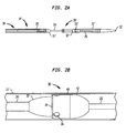
- a second embodiment of a delivery device 10' has a distal tip 12 and a catheter assembly 14' extending from the distal tip 12 to a proximal end (not shown) that includes a handle (not shown) for a user to control the delivery device 10'.
- the delivery device 10' is an exemplary transapical delivery device for a collapsible prosthetic heart valve.
- the catheter assembly 14' includes a proximal sheath 20 extending from the handle towards the distal tip 12, a distal sheath 22' extending from the distal tip 12 towards the handle, a hollow tube 26 that extends slidably from the proximal end through the proximal sheath 20 and attaches to the distal sheath 22' at the distal tip 12 of the delivery device 10', and a valve receiving compartment 28' configured to receive a prosthetic valve for delivery inside of a patient.
- the valve receiving compartment 28' is configured to receive a collapsible prosthetic heart valve.
- the valve receiving compartment 28' includes a proximal conical end 31' at the distal end of the proximal sheath 20, a distal conical end 32' spaced from the proximal conical end, and a retainer 30' located adjacent the distal conical end 32' and inside the distal sheath 22'.
- a hollow inner shaft 24' is connected at one end to the proximal conical end 31' and at the other end to the distal conical end 32', and slidably receives the hollow tube 26 therethrough.
- a collapsible valve is loaded into the valve receiving compartment 28' around the inner shaft 24' and between the conical ends 31' and 32', and the stent portion of the valve is coupled to the retainer 30'.
- the retainer 30' includes an outer piece 40, a support piece 42 located adjacent to the outer piece 40, and an inner piece (not shown, but attached to the outside of the inner shaft 24') that is coupled to the outer piece 40 so as to be rotatable relative thereto.
- the outer piece 40 defines one or more acceptances 36, each acceptance 36 being located at the retention edge 34 of the outer piece 40 and configured to receive a corresponding retention member of the stent portion of a collapsible prosthetic valve.
- Each acceptance 36 preferably has a similar shape and a slightly larger size than a conventional stent retention member so as to capture same readily, but with only a small amount of relief therebetween.
- a transapical prosthetic aortic valve delivery device e.g., the device 10' shown in FIGS. 2A and 2B
- the retention edge 34 is located at the proximal end of the outer piece 40, and the distal sheath 22' is moved in a distal direction to unsheathe and deploy the valve, with the proximal end of the valve unsheathed first.
- a retainer 30" suitable for use in the delivery device 10 shown in FIG. 1A or the delivery device 10' shown in FIG. 2A includes an alternate outer piece 40" having one or more acceptances 36", each acceptance 36" being located at the retention edge 34 of the outer piece 40" and configured to receive a corresponding retention member of the stent portion of a collapsible prosthetic valve.
- each acceptance 36" shown in FIG. 2C narrows as it approaches the retention edge 34, such that the end of the acceptance 36" that is farthest away from the retention edge 34 is wider than the portion of the acceptance 36" that is closer to the retention edge 34.
- the tapered shape of the acceptances 36" shown in FIG. 2C may allow a user to more easily load the retention members of a stent into the retainer 30", as compared to the shape of the acceptances 36 shown in FIGS. 1A and 2B .
- Acceptances 36" having a tapered shape may be used in any of the retainer embodiments disclosed herein.
- FIG. 3 another embodiment of a retainer 30a suitable for use in the delivery device 10 shown in FIG. 1A includes an outer piece 40a that is coupled to an inner piece 50a so as to be rotatable relative to same.
- the outer piece 40a defines one or more acceptances 36, each acceptance 36 being located at the retention edge 34 of the outer piece 40a and configured to receive a corresponding retention member of the stent portion of a collapsible valve.
- the retainer 30a is attached to a stiffening member 25 mounted on the hollow inner shaft 24.
- the outer piece 40a in the retainer 30a has a shape that resembles the combined shape of the outer piece 40 and the support piece 42 of the retainer 30.
- the inner piece 50a includes an annular ring 52a that is adapted to fit into a corresponding circumferential groove 44a defined in the outer piece 40a. Similar to the retainer 30 shown in FIG. 1B , the ring and the groove construction enables the outer piece 40a to freely rotate about the inner piece 50a but not slide longitudinally by any significant amount relative to the inner piece 50a.
- a further embodiment of a retainer 30b suitable for use in the delivery device 10 shown in FIG. 1A includes an inner piece 50b, an outer piece 40b rotatably coupled to the inner piece, and a support piece 42b located adjacent to the outer piece 40b and fixedly coupled to the inner piece.
- the outer piece 40b includes one or more acceptances 36, each of which is located at the retention edge 34 of the outer piece and configured to receive a corresponding retention member of the stent portion of a collapsible valve.
- the retainer 30b is attached to a stiffening member 25 mounted on the hollow inner shaft 24.
- the inner piece 50b includes an annular ring 52b that is adapted to fit into a corresponding circumferential groove 44b defined in the outer piece 40b. Similar to the retainer 30 shown in FIG. 1B , the ring 52b and the groove 44b are configured to enable the outer piece 40b to freely rotate about the inner piece 50b but not slide longitudinally by any significant amount relative to the inner piece.
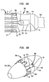
- yet another embodiment of a retainer 30c suitable for use in the delivery device 10 shown in FIG. 1A includes an outer piece 40c, a support piece 42c located adjacent to the outer piece 40c, and an inner piece 50c that is rotatably coupled to the outer piece 40c.
- the support piece 42c can either be attached to the outer piece 40c so as to be rotatable relative to the inner piece 50c, or fixedly attached to the inner piece 50c so that there is relative rotational movement between the outer piece 40c and the support piece 42c.
- the outer piece 40c includes one or more acceptances 36c, each being located at the retention edge 34 of the outer piece 40c.
- the retainer 30c includes a ring and groove configuration (not shown) that permits the outer piece 40c to freely rotate about the inner piece 50c but prevents significant longitudinal movement between the two.
- the stent portion 1 of a collapsible valve is shown coupled to the retainer 30c.
- the stent portion 1 includes a plurality of stent struts 2 that define cells 3 therebetween.
- At least one retention member 4 extends from an end of the stent portion 1.
- Each retention member 4 includes an aperture 5.
- the stent 1 containing the valve preferably is attached to the retainer 30c by retention members 4 protruding from the end of the stent 1 that is opposite the end at which the valve is located (i.e., the retention members 4 protrude from the aortic side of the stent 1).
- the position of retention members 4 in acceptances 36c is independently longitudinally adjustable by the user. That is, one or more acceptances 36c include a pin 60 that is manually slidable in the acceptance in the longitudinal direction of the stent 1.
- each of the acceptances 36c includes such a slidable pin 60.
- Each pin 60 is coupled to an actuator wire 64 that may be independently pushed or pulled by a user to slide the pin along a longitudinal slot 62.
- the retention members 4 of the stent 1 are coupled to the retainer 30c by inserting same into a corresponding acceptance 36c with the pin 60 thereof inserted through the aperture 5 of the retention member.
- a user can adjust the longitudinal position of the pin 60 of each acceptance 36c, and with it, the longitudinal position of the corresponding retention member 4.
- the valve When the delivery device 10 is being used to deliver a collapsible valve into a patient, the valve may become cocked at an angle relative to the retainer 30c and the acceptances 36c thereof, and as a result, may not readily release therefrom.
- the ability to independently adjust the longitudinal position of each retention member 4 relative to the retainer 30c may allow the valve to be straightened to facilitate its release from the delivery device 10.
- the stent portion of the prosthetic valve may become twisted about its longitudinal axis relative to the retainer 30c due to the maneuvering of the delivery device through the vasculature, thereby applying torsional stress both to the stent and to the stent's retention members that are coupled to the acceptances 36c.
- these torsional stresses will cause the outer piece to rotate relative to the inner piece 50c and the sheath 22, releasing the torsional forces acting on the stent and its retention members.
- the user may independently adjust the longitudinal position of one or more retention members 4 relative to the retainer 30c and the acceptances 36c thereof, realigning the stent and enabling continued release of the valve.
- the retainer 30c having the capability to independently longitudinally adjust the position of retention members 4 in the acceptances 36c is shown and described with reference to the rotatable retainer embodiments shown in FIGS. 1A through 4
- the capability to independently longitudinally adjust the position of retention members 4 in the acceptances 36c may be incorporated into the embodiments shown in FIGS. 6A through 10 that include the feature wherein the length of the acceptances are greater than a length of the respective retention members in the longitudinal direction.
- a still further embodiment of a retainer 30d suitable for use in the delivery devices 10 and 10' shown in FIGS. 1A and 2A includes an inner piece 50d, an outer piece 40d that is rotatably coupled to the inner piece, and a support piece 42d coupled to the inner piece adjacent to the outer piece 40d.
- the support piece 42d can either be attached to the outer piece 40d so as to be rotatable relative to the inner piece 50d, or fixedly attached to the inner piece 50d so that there may be relative rotational movement between the outer piece 40d and the support piece 42d.
- the ability of the outer piece 40d to freely rotate relative to the inner piece 50d may provide the beneficial stent stress-reduction effects discussed above with respect to the embodiments of FIGS. 1-5 .
- outer piece 40d is described herein as rotatably coupled to the inner piece 50d, in some embodiments, the outer piece 40d may be fixed to the inner piece 50d.
- the other features of the retainer 30d e.g. , the recesses 38
- the outer piece 40d is either fixed or rotatable relative to the inner piece 50d.
- the outer pieces shown in FIGS. 7-10 may be either fixed or rotatable relative to the corresponding inner pieces shown in those figures.
- the retainer 30d may be located adjacent to a proximal conical end 31d that is suitable for coupling to the inner shaft 24 of the delivery device.
- the retainer 30d may be located adjacent to a distal conical end 32d that is suitable for coupling to the inner shaft 24' of the delivery device.
- the outer piece 40d includes one or more acceptances 36d, each extending from the retention edge 34 of the outer piece 40d and configured to receive a corresponding retention member 4 of the stent portion of a collapsible prosthetic valve.
- Each acceptance 36d has an elongated shape, with protuberances 37d projecting towards one another to define a narrowed neck 39d that limits the longitudinal movement of a corresponding retention member 4 toward the retention edge 34.
- Neck 39d is positioned in acceptance 36d so as to define a pocket 41d spaced from retention edge 34.
- pocket 41d has a length in the longitudinal direction that is substantially larger than the size of the retention member 4.
- the retainer 30d (and all of the other retainers disclosed herein) may have any number of acceptances, including for example, one, two, four, six, or eight acceptances. Further, each acceptance 36d (and all of the other acceptances disclosed herein) may have only a single protuberance 37d defining the neck 39d, or any number of protuberances greater than two.
- the retainers described herein may be used with stents 1 having any number of retention members 4, including for example, one, two, four, six, or eight retention members.
- the outer piece 40d further includes one or more recesses 38 extending inwardly from the retention edge 34 and configured to receive the V-shaped junction formed by the struts 2 at the end of the stent 1.
- the recesses 38 provide a limit to the longitudinal movement of a corresponding stent strut 2 relative to the retention edge 34. Furthermore, the recesses 38 fix the circumferential positions of the stent struts 2, preventing them from overlapping with one another and becoming otherwise entangled during the delivery and deployment of the prosthetic valve.
- the retention members 4 With a prosthetic valve assembled to the retainer 30d, as shown in FIG. 6A , the retention members 4 will be spaced from the end wall 43 of the pocket 41d. However, should any longitudinal force develop tending to push the prosthetic valve against the retainer 30d, the engagement of the stent struts 2 in the recesses 38 will prevent the longitudinal movement of the prosthetic valve relative to the retainer. As a result, the retention members 4 will remain spaced from the end walls 43 of the pockets 41d, and the compressive force between the stent 1 of the prosthetic valve and the retainer 30d will not be localized at the retention members, but rather will be distributed substantially uniformly around the circumference of the stent through stent struts 2.
- the recesses 38 may be generally U-shaped as shown in FIG. 6C or may have any other shape that can receive a corresponding stent strut 2 and serve the purposes just described.
- the retainer 30d includes an annular ring and groove configuration that permits the outer piece 40d to freely rotate about the inner piece 50d but prevents the outer piece from moving longitudinally relative to the inner piece.
- the recesses 38 of the retainer 30d may direct the forces acting between the retainer and the stent onto the stent struts 2 that do not support the retention members 4 as described above, rather than onto the retention members 4 themselves. As a result, these forces are more evenly distributed around the circumference of the stent 1. This can prevent the retention members 4 or the stent struts 2 that support the retention members 4 from being damaged or deformed.
- unsheathing of the prosthetic valve will produce frictional forces between the sheath 22 or 22' (see FIGS. 1A and 2A ) and the stent 1 that will either push or pull the stent 1 longitudinally against the retainer 30d.
- This longitudinal force will force the stent struts 2 into engagement with the bottoms of the recesses 38, while the retention members 4 remain spaced from the ends 43 of the pockets 41d, thereby preventing the application of a pushing force on the retention members.
- FIG. 7 Yet another embodiment of a retainer 30e is shown in FIG. 7 .
- the retainer 30e is suitable for use in the delivery devices 10 and 10' shown in FIGS. 1A and 2A , respectively.
- the retainer 30e is substantially the same as the retainer 30d described above. However, rather than having an end wall at the end of the pocket 41e remote from the retainer edge 34, such as the end wall 43 of the retainer 30d, the pockets 41e have an open end. It will be appreciated from the description above that the retention members 4 do not contact the end wall 43 of the retainer 30d during use of the deployment device to deploy or resheathe a prosthetic valve. Accordingly, the end wall 43 is not necessary and has been eliminated from the retainer 30e.
- FIG. 8 illustrates yet a further embodiment of a retainer 30f suitable for use in the delivery devices 10 and 10' shown in FIGS. 1A and 2A , respectively.
- the retainer 30f is substantially similar to the retainer 30e described above, except for the elimination of the recesses 38 extending inwardly from the retention edge 34.
- the retention edge 34 of the outer piece 40f provides a limit to the longitudinal movement of the stent struts 2 during the unsheathing or deployment of the prosthetic valve into a patient.
- the retainer 30f can not prevent the stent struts from overlapping with one another and becoming otherwise entangled during the use of the delivery device to deliver and deploy the prosthetic valve.
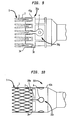
- FIG. 9 Still another embodiment of a retainer 30g is shown in FIG. 9 .
- the retainer 30g is suitable for use in the delivery devices 10 and 10' shown in FIGS. 1A and 2A , respectively.
- the retainer 30g is substantially similar to the retainers 30d and 30e described above, but differs in the configuration of the outer piece 40g, and in particular, in the configuration of the acceptances 36g.
- the acceptances 36g are oversized in both the longitudinal direction and in the circumferential direction.
- the acceptances 36g may be oversized relative to the retention members 4 in the circumferential direction by any amount, such as, for example, 1.5, 3, and 4 times the dimension of the retention member 4 in the circumferential direction.
- a circumferential dimension that is at least about two times the corresponding dimension of the retention members 4 is preferred.
- the large oversize of acceptances 36g facilitates the assembly of the stent portion of a prosthetic valve within the valve receiving compartment 28 or 28' and may facilitate the deployment of the prosthetic valve by minimizing the possibility that the retention members 4 will fail to be released by the acceptances.
- FIG. 10 Another embodiment of a retainer 30h suitable for use in the delivery devices 10 and 10' is shown in FIG. 10 .
- the retainer 30h is similar to the retainer 30f described above, but combines features of that retainer with features of the retainer 30g also described above. That is, the retainer 30h has a retention edge 34 devoid of the recesses 38 extending inwardly therefrom, as with the retainer 30f. Accordingly, the retention edge 34 of the outer piece 40h limits the longitudinal movement of the stent struts 2 during the unsheathing or deployment of a prosthetic valve.
- retainer 30h has a single acceptance region 36h that essentially eliminates any structure that would reside between the retention members 4 when the prosthetic valve is assembled to the retainer.
- the only structures that fix the position of the prosthetic valve relative to the retainer in the circumferential direction are the necks 39h that extend from the retention edge 34 to the acceptance region 36h.
- the engagement of the stent struts 2 with the retention edge 34 and the engagement of the retention members 4 with the necks 39h substantially prevent the longitudinal movement of the prosthetic valve relative to the retainer 30h.
- retainer embodiments have been described here in connection with retaining for deployment a prosthetic valve having a collapsible stent structure, all of the retainer embodiments may be used for other purposes.
- the various embodiments of retainers may be used to retain conventional collapsible stents that do not contain a valve.
- retention members may protrude from the annulus end of the stent portion of the valve for engagement with a retainer of the delivery device, such that the aortic end of the stent is remote from the retainer and may be unsheathed first.
- retention members may protrude from both the aortic and the annulus ends of the stent portion of the valve for engagement with a retainer.
Landscapes
- Health & Medical Sciences (AREA)
- Cardiology (AREA)
- Engineering & Computer Science (AREA)
- Biomedical Technology (AREA)
- Heart & Thoracic Surgery (AREA)
- Transplantation (AREA)
- Oral & Maxillofacial Surgery (AREA)
- Vascular Medicine (AREA)
- Life Sciences & Earth Sciences (AREA)
- Animal Behavior & Ethology (AREA)
- General Health & Medical Sciences (AREA)
- Public Health (AREA)
- Veterinary Medicine (AREA)
- Prostheses (AREA)
Description
- This application claims the benefit of the filing date of United States Provisional Patent Application No.
61/364,453 filed July 15, 2010 - The present invention is related to prosthetic heart valve replacement, and more particularly to devices, systems, and methods for transcatheter delivery of collapsible prosthetic heart valves.
- Prosthetic heart valves that are collapsible to a relatively small circumferential size can be delivered into a patient less invasively than valves that are not collapsible. For example, a collapsible valve may be delivered into a patient via a tube-like delivery apparatus such as a catheter, a trocar, a laparoscopic instrument, or the like. This collapsibility can avoid the need for a more invasive procedure such as full open-chest, open-heart surgery.
- Collapsible prosthetic heart valves typically take the form of a valve structure mounted on a stent. There are two types of stents on which collapsible valves are mounted: a self-expanding stent and a balloon-expandable stent. To place a collapsible valve into a delivery apparatus and ultimately into a patient, the valve must first be collapsed or crimped to reduce its circumferential size.
- When a collapsed valve has reached the desired implant site in the patient (e.g., at or near the annulus of the patient's heart valve that is to be replaced by the prosthetic valve), the prosthetic valve can be released from the delivery apparatus and re-expanded to full operating size.
- Despite the various improvements that have been made to the collapsible prosthetic heart valve delivery process, conventional delivery devices, systems, and methods suffer from some shortcomings. For example, the self-expanding collapsible valve may be held in a catheter by stent retention members that are inserted into the retainer portion of the catheter. During deployment of the self-expanding valve into the desired area (e.g., the aortic valve annulus), the high frictional force produced during unsheathing of the valve may cause high axial forces to be applied directly to the two or three retention members, which may damage or deform the stent struts that support the retention members.
- Furthermore, the delivery process may cause the stent to become twisted relative to the retainer portion of the catheter, which may make it difficult to release the valve because the stent retention members may catch on the retainer during deployment.
- There therefore is a need for further improvements to the devices, systems, and methods for transcatheter delivery of collapsible prosthetic heart valves. Among other advantages, the present invention may address one or more of these shortcomings.
-
WO 97/48343 -
WO 2006/124549 describes a medical implant delivery system maintaining an orientation between a guidewire lumen of an inner member of the system and a rapid-exchange port in an outer member. The medical device is disposed intermediate the inner and outer members. Once the guidewire lumen and the rapid exchange port are oriented, a friction or pressure-fit operates to maintain the orientation until deployment of the medical implant. -
DE 10 2004 062 296 - A delivery device for an implantable medical device, a system for implantable medical device delivery, and a method of prosthetic valve delivery are disclosed.
- A delivery device for an implantable medical device having at least one retention member at an end thereof includes a shaft extending in a longitudinal direction, an elongated sheath surrounding a longitudinal portion of the shaft, the sheath being slidable relative to the shaft in the longitudinal direction, a compartment defined inside of the sheath and adapted to receive the medical device in an assembled condition, a retainer positioned at one end of the compartment, the retainer including an inner piece and an outer piece mounted on the inner piece so as to be rotatable about the inner piece and constrained from movement relative to the inner piece in the longitudinal direction, and at least one acceptance in the retainer adapted to receive the retention member of the medical device in the assembled condition.
- One of the outer piece and the inner piece may include a circumferentially extending groove and another of the outer piece and the inner piece may include an annular ring assembled in the groove and permitting the outer piece to rotate about the inner piece. The retainer may further include a support piece mounted on the inner piece and fixedly connected to the outer piece, whereby the outer piece and the support piece are rotatable together about the inner piece. The medical device may include a self-expanding stent having a plurality of struts and the outer piece may have a retention edge facing the compartment and at least one recess extending in the longitudinal direction from an open end at the retention edge to a closed end, the recess being adapted to receive one of the plurality of struts at an end of the stent in the assembled condition.
- The acceptance may have a length in the longitudinal direction such that in the assembled condition the one of the plurality of struts contacts the closed end of the recess while the retention member is spaced from a closed end of the acceptance. The outer piece has a retention edge facing the compartment and the acceptance has a first region sized to receive the retention member, the acceptance including at least one protuberance defining a narrowed neck between the first region and the retention edge. The delivery device may also include a pin extending radially outward from the at least one acceptance, the pin being adapted to engage an aperture in the retention member, and an actuator coupled to the pin and adapted to move the pin in the longitudinal direction, thereby adjusting the longitudinal position of the retention member relative to the acceptance. The medical device may be a self-expanding collapsible prosthetic valve.
- A system for implantable medical device delivery includes a delivery device including a shaft extending in a longitudinal direction, an elongated sheath surrounding a longitudinal portion of the shaft, the sheath being slidable relative to the shaft in the longitudinal direction, a compartment defined inside of the sheath, a retainer positioned at one end of the compartment, the retainer including an inner piece and an outer piece mounted on the inner piece so as to be rotatable about the inner piece and constrained from movement relative to the inner piece in the longitudinal direction, and at least one acceptance in the retainer. The system for implantable medical device delivery also includes an implantable medical device assembled in the compartment, the medical device having at least one retention member at an end thereof, the retention member being positioned in the acceptance.
- One of the outer piece and the inner piece may include a circumferentially extending groove and another of the outer piece and the inner piece may include an annular ring assembled in the groove and permitting the outer piece to rotate about the inner piece. The retainer may further include a support piece mounted on the inner piece and fixedly connected to the outer piece, whereby the outer piece and the support piece are rotatable together about the inner piece. The medical device may include a self-expanding stent having a plurality of struts and the outer piece may have a retention edge facing the compartment and at least one recess extending in the longitudinal direction from an open end at the retention edge to a closed end, one of the plurality of struts at an end of the stent being assembled in the recess.
- The acceptance may have a length in the longitudinal direction such that the one of the plurality of struts contacts the closed end of the recess while the retention member is spaced from a closed end of the acceptance. The outer piece has a retention edge facing the compartment and the acceptance may have a first region sized to receive the retention member, the acceptance including at least one protuberance defining a narrowed neck between the first region and the retention edge. The system for implantable medical device delivery may also include a pin extending radially outward from the at least one acceptance and engaged in an aperture in the retention member, and an actuator coupled to the pin and adapted to move the pin in the longitudinal direction, thereby adjusting the longitudinal position of the retention member relative to the acceptance.
- A delivery device for an implantable medical device having at least one retention member at an end thereof includes a shaft extending in a longitudinal direction, an elongated sheath surrounding a longitudinal portion of the shaft, the sheath being slidable relative to the shaft in the longitudinal direction, a compartment defined inside of the sheath and adapted to receive the medical device in an assembled condition, a retainer positioned at one end of the compartment, the retainer having a retention edge facing the compartment, and at least one acceptance in the retainer adapted to receive the retention member of the medical device in the assembled condition, the acceptance having a length in the longitudinal direction such that in the assembled condition the length of the acceptance is greater than a length of the retention member in the longitudinal direction.
- The medical device may include a self-expanding stent having a plurality of struts and the retainer may have at least one recess extending in the longitudinal direction from an open end at the retention edge to a closed end, the recess being adapted to receive one of the plurality of struts at an end of the stent in the assembled condition. The acceptance may have a first region sized to receive the retention member, the acceptance including at least one protuberance defining a narrowed neck between the first region and the retention edge. The medical device may be a self-expanding collapsible prosthetic valve.
- The delivery device may also include a pin extending radially outward from the at least one acceptance, the pin being adapted to engage an aperture in the retention member, and an actuator coupled to the pin and adapted to move the pin in the longitudinal direction, thereby adjusting the longitudinal position of the retention member relative to the acceptance. In the assembled condition, the one of the plurality of struts may contact the closed end of the recess while the retention member is spaced from a closed end of the acceptance. The acceptance may have a first region sized to receive the retention member, the acceptance including at least one protuberance defining a narrowed neck between the first region and the retention edge.
- An exemplary method of prosthetic valve delivery includes providing a prosthetic valve having at least one retention member at an end thereof, mounting the valve in a compartment of a delivery device, the delivery device including a shaft, an elongated sheath surrounding a longitudinal portion of the shaft and slidable in longitudinal directions relative to the valve, a retainer positioned at one end of the compartment, and at least one acceptance in the retainer, the valve being mounted in the compartment with the retention member positioned in the acceptance, inserting the delivery device in a patient to position the valve at a target location, deploying the valve by sliding the sheath in a first one of the longitudinal directions relative to the valve, and adjusting the longitudinal position of the retention member relative to the acceptance during the deploying step.
- The valve may include a self-expanding stent having a plurality of struts and the retainer includes a recess facing the compartment and extending longitudinally from an open end to a closed end, the valve being mounted in the compartment with one of the struts positioned in the recess. The method may further include forcing the one of the struts into engagement with the recess during the deploying step, such that a longitudinal force is not exerted on the retention member. The acceptance may include at least one protuberance defining a narrowed neck in the acceptance.
- The exemplary method may further include resheathing the valve by sliding the sheath in a second one of the longitudinal directions relative to the valve opposite the first longitudinal direction, whereby an engagement of the retention member with the protuberance keeps the retention member positioned in the acceptance during the resheathing. The retainer may include a pin extending radially outward from the acceptance and engaged in an aperture in the retention member, and the delivery device includes an actuator coupled to the pin and adapted to move the pin in the longitudinal directions. The method may further include moving the actuator in at least one of the longitudinal directions to adjust the longitudinal position of the retention member relative to the acceptance.
- An exemplary method of prosthetic valve delivery includes providing a prosthetic valve having at least one retention member at an end thereof and a self-expanding stent having a plurality of struts, mounting the valve in a compartment of a delivery device, the delivery device including a shaft, an elongated sheath surrounding a longitudinal portion of the shaft and slidable in longitudinal directions relative to the valve, a retainer positioned at one end of the compartment and having a recess facing the compartment and extending longitudinally from an open end to a closed end, and at least one acceptance in the retainer, the valve being mounted in the compartment with the retention member positioned in the acceptance and with one of the struts positioned in the recess, inserting the delivery device in a patient to position the valve at a target location, and deploying the valve by sliding the sheath in a first one of the longitudinal directions relative to the valve, the deploying step forcing the one of the struts into engagement with the recess such that a longitudinal force is not exerted on the retention member.
- The acceptance may include at least one protuberance defining a narrowed neck in the acceptance. The method may further include resheathing the valve by sliding the sheath in a second one of the longitudinal directions relative to the valve opposite the first longitudinal direction, whereby an engagement of the retention member with the protuberance keeps the retention member positioned in the acceptance during the resheathing.
- Various embodiments of the present invention will now be discussed with reference to the appended drawings. It is appreciated that these drawings depict only some embodiments of the invention and are therefore not to be considered limiting of its scope.
-
FIG. 1A is a side view of a transfemoral delivery device for a collapsible prosthetic heart valve; -
FIG. 1B is a longitudinal cross-section of the retainer of the delivery device depicted inFIG. 1A , shown without the proximal conical end and the distal sheath; -
FIG. 2A is a side view of a transapical delivery device for a collapsible prosthetic heart valve; -
FIG. 2B is a side view of the retainer of the delivery device ofFIG. 2A ; -
FIG. 2C is an enlarged side view of another embodiment of a retainer suitable for use in the delivery device ofFIG. 2A ; -
FIG. 3 is a longitudinal cross-section of another embodiment of a retainer suitable for use in the delivery device ofFIG. 1A ; -
FIG. 4 is a longitudinal cross-section of another embodiment of a retainer suitable for use in the delivery device ofFIG. 1A ; -
FIG. 5A is a side perspective view of another embodiment of a retainer suitable for use in the delivery device ofFIG. 1A , shown holding a stent in a compressed state inside a distal sheath; -
FIG. 5B is an enlarged side perspective view of a portion of the retainer depicted inFIG. 5A ; -
FIG. 6A is a side view of another embodiment of a retainer suitable for use in the delivery device ofFIGS. 1A and2A , shown holding a stent; -
FIG. 6B is a perspective view of the retainer depicted inFIG. 6A , shown with a retainer cone; -
FIG. 6C is a developed view of the retainer depicted inFIG. 6B ; -
FIG. 7 is a side view of another embodiment of a retainer suitable for use in the delivery device ofFIGS. 1A and2A , shown holding a stent; -
FIG. 8 is a side view of another embodiment of a retainer suitable for use in the delivery device ofFIGS. 1A and2A , shown holding a stent; -
FIG. 9 is a side view of another embodiment of a retainer suitable for use in the delivery device ofFIGS. 1A and2A , shown holding a stent; and -
FIG. 10 is a side view of another embodiment of a retainer suitable for use in the delivery device ofFIGS. 1A and2A , shown holding a stent. - As used herein, the terms "proximal" and "distal" are to be taken as relative to a surgeon using the disclosed delivery devices. "Proximal" is to be understood as relatively close to the surgeon and "distal" is to be understood as relatively farther away from the surgeon.
- Referring now to
FIG. 1A to illustrate the structure and function of the present invention, a first embodiment of adelivery device 10 has adistal tip 12 and acatheter assembly 14 extending from thedistal tip 12 to a proximal end (not shown) that includes a handle (not shown) for a user to control thedelivery device 10. Thedelivery device 10 is an exemplary transfemoral delivery device for a collapsible prosthetic heart valve. - Although the
delivery device 10 is a transfemoral delivery device, the inventive retainers shown and described in this application may be configured to be used with a transapical delivery device (e.g., the device 10' shown inFIGS. 2A and 2B ) or other types of tube-like delivery devices for collapsible stents. - The
catheter assembly 14 includes asheath 22 extending from the handle towards thedistal tip 12, a hollowinner shaft 24 located inside of thesheath 22 and extending from the handle to thedistal tip 12, and avalve receiving compartment 28 configured to receive a prosthetic valve for delivery inside of a patient. - The
valve receiving compartment 28 is configured to receive a collapsible prosthetic heart valve (e.g., stent portions of collapsible prosthetic valves are shown inFIGS. 5A ,6A , and7-10 ). Thevalve receiving compartment 28 includes aretainer 30 located inside thesheath 22, a proximalconical end 31 adjacent theretainer 30, and a distalconical end 32 spaced from theretainer 30. Theconical end 32 is joined to theinner shaft 24 at one end of thevalve receiving compartment 28, and theconical end 31 and theretainer 30 are joined to a stiffeningmember 25 mounted on theinner shaft 24 at the other end of thevalve receiving compartment 28. Preferably, theinner shaft 24 and the stiffeningmember 25 have the same internal diameter, adapted to receive a guide wire (not shown). Alternatively, in any of the delivery device embodiments described herein, theinner shaft 24 and the stiffeningmember 25 may be a single unitary shaft. For delivery into a patient, a collapsible valve is loaded into thevalve receiving compartment 28 around theinner shaft 24 and between conical ends 31 and 32, and the stent portion of the valve is coupled to theretainer 30. - Referring now to
FIG. 1B , theretainer 30 includes anouter piece 40, asupport piece 42 located adjacent to theouter piece 40, and aninner piece 50 that is coupled to theouter piece 40 so as to be rotatable relative thereto. Theouter piece 40 defines one ormore acceptances 36, eachacceptance 36 being located at theretention edge 34 of theouter piece 40 and configured to receive a corresponding retention member of a stent portion of the collapsible valve (see, for example,retention member 4 inFIG. 6A ). Eachacceptance 36 preferably has a similar shape and a slightly larger size than a conventional stent retention member so as to capture same readily, but with only a small amount of relief therebetween. Formingacceptances 36 with an appropriate shape and size prevents longitudinal movement of the valve within thevalve receiving compartment 28, such as during deployment or resheathing procedures. - In the embodiment shown in
FIG. 1B , theouter piece 40 and thesupport piece 42 are attached together (e.g., via welding or any other known joining technique) so that they are rotatable together relative to theinner piece 50. In other embodiments (such as the embodiment shown inFIG. 4 ), the outer piece and the support piece may be rotatable relative to each other. For example, the support piece may be attached to the inner piece, such that the outer piece may rotate relative to both the support piece and the inner piece. - The
inner piece 50 includes anannular ring 52 that is adapted to fit into a correspondingcircumferential groove 44 defined in theouter piece 40. Thering 52 and thegroove 44 are configured such that theouter piece 40 and thesupport piece 42 can freely rotate about theinner piece 50 but not slide longitudinally by any significant amount relative to the inner piece. In the embodiments shown, a small amount of longitudinal movement is permitted between theouter piece 40 and theinner piece 50 so as to minimize frictional braking forces between these elements, but thering 52 and thegroove 44 retain theouter piece 40 and thesupport piece 42 on theinner piece 50 during use of theretainer 30. - To load the
delivery device 10 with a collapsible prosthetic valve, a user attaches the stent portion of the prosthetic valve to theouter piece 40 and compresses or crimps the valve until it fits inside thesheath 22, which holds the valve in a compressed state until the user decides to deploy the valve. When the valve is later deployed by unsheathing, the stent self-expands and is ultimately disengaged from theouter piece 40. If the valve has not been fully deployed, i.e., if a portion of the valve remains in a collapsed state beneathsheath 22, the valve may be resheathed by sliding the sheath back over the portion of the stent that has expanded, thereby recollapsing the expanded portion of the stent. - Regardless of whether a valve is to be delivered transapically or transfemorally into a patient to replace a native valve (e.g., the patient's aortic valve), the stent portion of the valve preferably is attached to the retainer by retention members protruding from the end of the stent that is opposite the end at which the valve is located (i.e., the retention members protrude from the aortic side of the stent). Preferably, the retention members are positioned at the end of the valve that is to be deployed last, i.e., the end of the valve that will be covered by the sheath the longest.
- For example, in a transfemoral prosthetic aortic valve delivery device (e.g., the
device 10 shown inFIG. 1A ), theretention edge 34 of theouter piece 40 is located at the distal end of the outer piece, and thesheath 22 is moved in a proximal direction to unsheathe and deploy the valve, with the distal end of the valve unsheathed first. - The
retention edge 34 of theouter piece 40 may have a chamfered outer edge, which may help reduce frictional forces acting between thesheath 22 and theouter piece 40 during unsheathing and resheathing of a stent. The retention edge of any of the retainer embodiments disclosed herein may have chamfered outer edges. - When the
delivery device 10 is being used to deliver a collapsible valve into a patient, the ability of theouter piece 40 to freely rotate about theinner piece 50 may allow theouter piece 40 to move to a circumferential position that minimizes the twisting forces experienced by a stent that is coupled to theacceptances 36. - For example, as the
delivery device 10 is advanced into a patient, such as through the femoral artery towards the aorta, the stent portion of the prosthetic valve may become twisted about its longitudinal axis relative to theretainer 30 due to the maneuvering of the delivery device through the vasculature, thereby applying torsional stress both to the stent and to the stent's retention members that are coupled to theacceptances 36. However, as theouter piece 40 is free to rotate, these torsional stresses will cause the outer piece to rotate relative to theinner piece 50 and thesheath 22, releasing the torsional forces acting on the stent and its retention members. - Referring to
FIG. 2A , a second embodiment of a delivery device 10' has adistal tip 12 and a catheter assembly 14' extending from thedistal tip 12 to a proximal end (not shown) that includes a handle (not shown) for a user to control the delivery device 10'. The delivery device 10' is an exemplary transapical delivery device for a collapsible prosthetic heart valve. - The catheter assembly 14' includes a
proximal sheath 20 extending from the handle towards thedistal tip 12, a distal sheath 22' extending from thedistal tip 12 towards the handle, ahollow tube 26 that extends slidably from the proximal end through theproximal sheath 20 and attaches to the distal sheath 22' at thedistal tip 12 of the delivery device 10', and a valve receiving compartment 28' configured to receive a prosthetic valve for delivery inside of a patient. - The valve receiving compartment 28' is configured to receive a collapsible prosthetic heart valve. The valve receiving compartment 28' includes a proximal conical end 31' at the distal end of the
proximal sheath 20, a distalconical end 32' spaced from the proximal conical end, and a retainer 30' located adjacent the distalconical end 32' and inside the distal sheath 22'. A hollow inner shaft 24' is connected at one end to the proximal conical end 31' and at the other end to the distalconical end 32', and slidably receives thehollow tube 26 therethrough. For delivery into a patient, a collapsible valve is loaded into the valve receiving compartment 28' around the inner shaft 24' and between the conical ends 31' and 32', and the stent portion of the valve is coupled to the retainer 30'. - Referring now to
FIG. 2B , the retainer 30' includes anouter piece 40, asupport piece 42 located adjacent to theouter piece 40, and an inner piece (not shown, but attached to the outside of the inner shaft 24') that is coupled to theouter piece 40 so as to be rotatable relative thereto. Theouter piece 40 defines one ormore acceptances 36, eachacceptance 36 being located at theretention edge 34 of theouter piece 40 and configured to receive a corresponding retention member of the stent portion of a collapsible prosthetic valve. Eachacceptance 36 preferably has a similar shape and a slightly larger size than a conventional stent retention member so as to capture same readily, but with only a small amount of relief therebetween. - In a transapical prosthetic aortic valve delivery device (e.g., the device 10' shown in
FIGS. 2A and 2B ), theretention edge 34 is located at the proximal end of theouter piece 40, and the distal sheath 22' is moved in a distal direction to unsheathe and deploy the valve, with the proximal end of the valve unsheathed first. - Referring now to
FIG. 2C , aretainer 30" suitable for use in thedelivery device 10 shown inFIG. 1A or the delivery device 10' shown inFIG. 2A includes an alternateouter piece 40" having one ormore acceptances 36", eachacceptance 36" being located at theretention edge 34 of theouter piece 40" and configured to receive a corresponding retention member of the stent portion of a collapsible prosthetic valve. - Compared to the
acceptances 36 shown inFIGS. 1A and2B , eachacceptance 36" shown inFIG. 2C narrows as it approaches theretention edge 34, such that the end of theacceptance 36" that is farthest away from theretention edge 34 is wider than the portion of theacceptance 36" that is closer to theretention edge 34. The tapered shape of theacceptances 36" shown inFIG. 2C may allow a user to more easily load the retention members of a stent into theretainer 30", as compared to the shape of theacceptances 36 shown inFIGS. 1A and2B .Acceptances 36" having a tapered shape may be used in any of the retainer embodiments disclosed herein. - Referring now to
FIG. 3 , another embodiment of aretainer 30a suitable for use in thedelivery device 10 shown inFIG. 1A includes anouter piece 40a that is coupled to aninner piece 50a so as to be rotatable relative to same. Theouter piece 40a defines one ormore acceptances 36, eachacceptance 36 being located at theretention edge 34 of theouter piece 40a and configured to receive a corresponding retention member of the stent portion of a collapsible valve. Theretainer 30a is attached to a stiffeningmember 25 mounted on the hollowinner shaft 24. - The
outer piece 40a in theretainer 30a has a shape that resembles the combined shape of theouter piece 40 and thesupport piece 42 of theretainer 30. Theinner piece 50a includes anannular ring 52a that is adapted to fit into a correspondingcircumferential groove 44a defined in theouter piece 40a. Similar to theretainer 30 shown inFIG. 1B , the ring and the groove construction enables theouter piece 40a to freely rotate about theinner piece 50a but not slide longitudinally by any significant amount relative to theinner piece 50a. - Referring now to
FIG. 4 , a further embodiment of aretainer 30b suitable for use in thedelivery device 10 shown inFIG. 1A includes aninner piece 50b, anouter piece 40b rotatably coupled to the inner piece, and asupport piece 42b located adjacent to theouter piece 40b and fixedly coupled to the inner piece. As a result, as theouter piece 40b rotates relative to theinner piece 50b, it will also rotate relative to thesupport piece 42b. Theouter piece 40b includes one ormore acceptances 36, each of which is located at theretention edge 34 of the outer piece and configured to receive a corresponding retention member of the stent portion of a collapsible valve. Theretainer 30b is attached to a stiffeningmember 25 mounted on the hollowinner shaft 24. - The
inner piece 50b includes anannular ring 52b that is adapted to fit into a correspondingcircumferential groove 44b defined in theouter piece 40b. Similar to theretainer 30 shown inFIG. 1B , thering 52b and thegroove 44b are configured to enable theouter piece 40b to freely rotate about theinner piece 50b but not slide longitudinally by any significant amount relative to the inner piece. - Referring now to
FIGS. 5A and 5B , yet another embodiment of aretainer 30c suitable for use in thedelivery device 10 shown inFIG. 1A includes anouter piece 40c, asupport piece 42c located adjacent to theouter piece 40c, and aninner piece 50c that is rotatably coupled to theouter piece 40c. Thesupport piece 42c can either be attached to theouter piece 40c so as to be rotatable relative to theinner piece 50c, or fixedly attached to theinner piece 50c so that there is relative rotational movement between theouter piece 40c and thesupport piece 42c. Theouter piece 40c includes one ormore acceptances 36c, each being located at theretention edge 34 of theouter piece 40c. - Similar to the
retainer 30 shown inFIG. 1B , theretainer 30c includes a ring and groove configuration (not shown) that permits theouter piece 40c to freely rotate about theinner piece 50c but prevents significant longitudinal movement between the two. - The
stent portion 1 of a collapsible valve is shown coupled to theretainer 30c. Thestent portion 1 includes a plurality of stent struts 2 that definecells 3 therebetween. At least oneretention member 4 extends from an end of thestent portion 1. Eachretention member 4 includes anaperture 5. As mentioned above with respect to theretainer 30, regardless of whether a valve is to be delivered transapically or transfemorally into a patient to replace a native valve (e.g., the patient's aortic valve), thestent 1 containing the valve preferably is attached to theretainer 30c byretention members 4 protruding from the end of thestent 1 that is opposite the end at which the valve is located (i.e., theretention members 4 protrude from the aortic side of the stent 1). - In the
retainer 30c, the position ofretention members 4 inacceptances 36c is independently longitudinally adjustable by the user. That is, one ormore acceptances 36c include apin 60 that is manually slidable in the acceptance in the longitudinal direction of thestent 1. Preferably, each of theacceptances 36c includes such aslidable pin 60. Eachpin 60 is coupled to anactuator wire 64 that may be independently pushed or pulled by a user to slide the pin along alongitudinal slot 62. Theretention members 4 of thestent 1 are coupled to theretainer 30c by inserting same into acorresponding acceptance 36c with thepin 60 thereof inserted through theaperture 5 of the retention member. Thus, by pulling the correspondingactuator wire 64 proximally or pushing the wire distally, a user can adjust the longitudinal position of thepin 60 of eachacceptance 36c, and with it, the longitudinal position of thecorresponding retention member 4. - When the
delivery device 10 is being used to deliver a collapsible valve into a patient, the valve may become cocked at an angle relative to theretainer 30c and theacceptances 36c thereof, and as a result, may not readily release therefrom. The ability to independently adjust the longitudinal position of eachretention member 4 relative to theretainer 30c may allow the valve to be straightened to facilitate its release from thedelivery device 10. - For example, as the
delivery device 10 is advanced into a patient, such as through the femoral artery towards the aorta, the stent portion of the prosthetic valve may become twisted about its longitudinal axis relative to theretainer 30c due to the maneuvering of the delivery device through the vasculature, thereby applying torsional stress both to the stent and to the stent's retention members that are coupled to theacceptances 36c. However, as theouter piece 40c is free to rotate, these torsional stresses will cause the outer piece to rotate relative to theinner piece 50c and thesheath 22, releasing the torsional forces acting on the stent and its retention members. If the user detects stress building up in thestent 1 or a misalignment of thestent 1 relative to theretainer 30c, potentially preventing the valve from being fully deployed or damaging theretention members 4, the user may independently adjust the longitudinal position of one ormore retention members 4 relative to theretainer 30c and theacceptances 36c thereof, realigning the stent and enabling continued release of the valve. - Although the
retainer 30c having the capability to independently longitudinally adjust the position ofretention members 4 in theacceptances 36c is shown and described with reference to the rotatable retainer embodiments shown inFIGS. 1A through 4 , the capability to independently longitudinally adjust the position ofretention members 4 in theacceptances 36c may be incorporated into the embodiments shown inFIGS. 6A through 10 that include the feature wherein the length of the acceptances are greater than a length of the respective retention members in the longitudinal direction. - Referring now to
FIGS. 6A-6C , a still further embodiment of aretainer 30d suitable for use in thedelivery devices 10 and 10' shown inFIGS. 1A and2A includes aninner piece 50d, anouter piece 40d that is rotatably coupled to the inner piece, and asupport piece 42d coupled to the inner piece adjacent to theouter piece 40d. Thesupport piece 42d can either be attached to theouter piece 40d so as to be rotatable relative to theinner piece 50d, or fixedly attached to theinner piece 50d so that there may be relative rotational movement between theouter piece 40d and thesupport piece 42d. The ability of theouter piece 40d to freely rotate relative to theinner piece 50d may provide the beneficial stent stress-reduction effects discussed above with respect to the embodiments ofFIGS. 1-5 . - Although the
outer piece 40d is described herein as rotatably coupled to theinner piece 50d, in some embodiments, theouter piece 40d may be fixed to theinner piece 50d. The other features of theretainer 30d (e.g., the recesses 38) may be included in embodiments in which theouter piece 40d is either fixed or rotatable relative to theinner piece 50d. Similarly, the outer pieces shown inFIGS. 7-10 may be either fixed or rotatable relative to the corresponding inner pieces shown in those figures. - In a transfemoral delivery device such as the
device 10 shown inFIG. 1A , theretainer 30d may be located adjacent to a proximal conical end 31d that is suitable for coupling to theinner shaft 24 of the delivery device. On the other hand, in a transapical delivery device such as the device 10' shown inFIG. 2A , theretainer 30d may be located adjacent to a distal conical end 32d that is suitable for coupling to the inner shaft 24' of the delivery device. - The
outer piece 40d includes one ormore acceptances 36d, each extending from theretention edge 34 of theouter piece 40d and configured to receive acorresponding retention member 4 of the stent portion of a collapsible prosthetic valve. Eachacceptance 36d has an elongated shape, withprotuberances 37d projecting towards one another to define a narrowedneck 39d that limits the longitudinal movement of acorresponding retention member 4 toward theretention edge 34.Neck 39d is positioned inacceptance 36d so as to define apocket 41d spaced fromretention edge 34. As can be seen inFIG. 6A ,pocket 41d has a length in the longitudinal direction that is substantially larger than the size of theretention member 4. - Although three
acceptances 36d are shown in the embodiment ofFIG. 6C , theretainer 30d (and all of the other retainers disclosed herein) may have any number of acceptances, including for example, one, two, four, six, or eight acceptances. Further, eachacceptance 36d (and all of the other acceptances disclosed herein) may have only asingle protuberance 37d defining theneck 39d, or any number of protuberances greater than two. Although threeretention members 4 are described as being engaged in the threerespective acceptances 36d in this embodiment (and in the other embodiments described herein), the retainers described herein may be used withstents 1 having any number ofretention members 4, including for example, one, two, four, six, or eight retention members. - The
outer piece 40d further includes one ormore recesses 38 extending inwardly from theretention edge 34 and configured to receive the V-shaped junction formed by thestruts 2 at the end of thestent 1. Therecesses 38 provide a limit to the longitudinal movement of acorresponding stent strut 2 relative to theretention edge 34. Furthermore, therecesses 38 fix the circumferential positions of the stent struts 2, preventing them from overlapping with one another and becoming otherwise entangled during the delivery and deployment of the prosthetic valve. - With a prosthetic valve assembled to the
retainer 30d, as shown inFIG. 6A , theretention members 4 will be spaced from theend wall 43 of thepocket 41d. However, should any longitudinal force develop tending to push the prosthetic valve against theretainer 30d, the engagement of the stent struts 2 in therecesses 38 will prevent the longitudinal movement of the prosthetic valve relative to the retainer. As a result, theretention members 4 will remain spaced from theend walls 43 of thepockets 41d, and the compressive force between thestent 1 of the prosthetic valve and theretainer 30d will not be localized at the retention members, but rather will be distributed substantially uniformly around the circumference of the stent through stent struts 2. In consideration of the foregoing, it will be appreciated that therecesses 38 may be generally U-shaped as shown inFIG. 6C or may have any other shape that can receive acorresponding stent strut 2 and serve the purposes just described. - Similar to the
retainer 30 shown inFIG. 1B , theretainer 30d includes an annular ring and groove configuration that permits theouter piece 40d to freely rotate about theinner piece 50d but prevents the outer piece from moving longitudinally relative to the inner piece. - During unsheathing of the
stent 1 to deploy a collapsible valve into a desired location in a patient, therecesses 38 of theretainer 30d may direct the forces acting between the retainer and the stent onto the stent struts 2 that do not support theretention members 4 as described above, rather than onto theretention members 4 themselves. As a result, these forces are more evenly distributed around the circumference of thestent 1. This can prevent theretention members 4 or the stent struts 2 that support theretention members 4 from being damaged or deformed. - For example, unsheathing of the prosthetic valve will produce frictional forces between the
sheath 22 or 22' (seeFIGS. 1A and2A ) and thestent 1 that will either push or pull thestent 1 longitudinally against theretainer 30d. This longitudinal force will force the stent struts 2 into engagement with the bottoms of therecesses 38, while theretention members 4 remain spaced from theends 43 of thepockets 41d, thereby preventing the application of a pushing force on the retention members. - During resheathing of the prosthetic valve, for example, when a user decides that the positioning of the valve in the patient needs to be adjusted, frictional forces will be produced between the
sheath 22 or 22' and thestent 1 that will tend to push or pull thestent 1 out of engagement with theretainer 30d. In such an event, theretention members 4 are prevented from moving further away from theends 43 of thepockets 41d by the protuberances 37. - Yet another embodiment of a
retainer 30e is shown inFIG. 7 . Theretainer 30e is suitable for use in thedelivery devices 10 and 10' shown inFIGS. 1A and2A , respectively. Theretainer 30e is substantially the same as theretainer 30d described above. However, rather than having an end wall at the end of thepocket 41e remote from theretainer edge 34, such as theend wall 43 of theretainer 30d, thepockets 41e have an open end. It will be appreciated from the description above that theretention members 4 do not contact theend wall 43 of theretainer 30d during use of the deployment device to deploy or resheathe a prosthetic valve. Accordingly, theend wall 43 is not necessary and has been eliminated from theretainer 30e. -
FIG. 8 illustrates yet a further embodiment of aretainer 30f suitable for use in thedelivery devices 10 and 10' shown inFIGS. 1A and2A , respectively. Theretainer 30f is substantially similar to theretainer 30e described above, except for the elimination of therecesses 38 extending inwardly from theretention edge 34. Thus, in theretainer 30f, theretention edge 34 of theouter piece 40f provides a limit to the longitudinal movement of the stent struts 2 during the unsheathing or deployment of the prosthetic valve into a patient. However, as theretention edge 34 does not capture the stent struts 2 individually, theretainer 30f can not prevent the stent struts from overlapping with one another and becoming otherwise entangled during the use of the delivery device to deliver and deploy the prosthetic valve. - Still another embodiment of a
retainer 30g is shown inFIG. 9 . Theretainer 30g is suitable for use in thedelivery devices 10 and 10' shown inFIGS. 1A and2A , respectively. Theretainer 30g is substantially similar to theretainers acceptances 36g. Rather than having acceptances that fit closely to theretention members 4 in the circumferential direction but which have excess free space in the longitudinal direction as with theacceptances acceptances 36g are oversized in both the longitudinal direction and in the circumferential direction. In that regard, theacceptances 36g may be oversized relative to theretention members 4 in the circumferential direction by any amount, such as, for example, 1.5, 3, and 4 times the dimension of theretention member 4 in the circumferential direction. A circumferential dimension that is at least about two times the corresponding dimension of theretention members 4 is preferred. The large oversize ofacceptances 36g facilitates the assembly of the stent portion of a prosthetic valve within thevalve receiving compartment 28 or 28' and may facilitate the deployment of the prosthetic valve by minimizing the possibility that theretention members 4 will fail to be released by the acceptances. - Another embodiment of a
retainer 30h suitable for use in thedelivery devices 10 and 10' is shown inFIG. 10 . Theretainer 30h is similar to theretainer 30f described above, but combines features of that retainer with features of theretainer 30g also described above. That is, theretainer 30h has aretention edge 34 devoid of therecesses 38 extending inwardly therefrom, as with theretainer 30f. Accordingly, theretention edge 34 of the outer piece 40h limits the longitudinal movement of the stent struts 2 during the unsheathing or deployment of a prosthetic valve. However, rather than having acceptances that fit closely toretention members 4 in the circumferential direction as inretainer 30f,retainer 30h has asingle acceptance region 36h that essentially eliminates any structure that would reside between theretention members 4 when the prosthetic valve is assembled to the retainer. Hence, in theretainer 30h, the only structures that fix the position of the prosthetic valve relative to the retainer in the circumferential direction are thenecks 39h that extend from theretention edge 34 to theacceptance region 36h. Nonetheless, the engagement of the stent struts 2 with theretention edge 34 and the engagement of theretention members 4 with thenecks 39h substantially prevent the longitudinal movement of the prosthetic valve relative to theretainer 30h. - Although the various retainer embodiments have been described here in connection with retaining for deployment a prosthetic valve having a collapsible stent structure, all of the retainer embodiments may be used for other purposes. In particular, the various embodiments of retainers may be used to retain conventional collapsible stents that do not contain a valve.
- Although the invention herein has been described with reference to particular embodiments in which the annulus end of a prosthetic valve is deployed first, it is to be understood that the invention contemplates embodiments in which the aortic end of a valve is deployed first. In such embodiments (not shown), retention members may protrude from the annulus end of the stent portion of the valve for engagement with a retainer of the delivery device, such that the aortic end of the stent is remote from the retainer and may be unsheathed first. In still other embodiments (not shown), retention members may protrude from both the aortic and the annulus ends of the stent portion of the valve for engagement with a retainer.
- Although the invention herein has been described with reference to particular embodiments, it is to be understood that these embodiments are merely illustrative of the principles and applications of the present invention. It is therefore to be understood that numerous modifications may be made to the illustrative embodiments and that other arrangements may be devised without departing from the scope of the present invention as defined by the appended claims.
- It will be appreciated that the various dependent claims and the features set forth therein can be combined in different ways than presented in the initial claims. It will also be appreciated that the features described in connection with individual embodiments may be shared with others of the described embodiments.
Claims (14)
- A system for implantable medical device delivery, the system comprising a delivery device (10) for an implantable medical device having at least one retention member (4) at an end thereof, the delivery device comprising:a shaft (24) extending in a longitudinal direction;an elongated sheath (22) surrounding a longitudinal portion of the shaft, the sheath being slidable relative to the shaft in the longitudinal direction;a compartment (28) defined inside of the sheath and adapted to receive the medical device (1) in an assembled condition characterised in havinga retainer (30) positioned at one end of the compartment (28), the retainer including an inner piece (50) and an outer piece (40) mounted on the inner piece so as to be rotatable about the inner piece and constrained from movement relative to the inner piece in the longitudinal direction; andat least one acceptance (36) in the retainer (30) adapted to receive the retention member (4) of the medical device (1) in the assembled condition,wherein the outer piece (40) has a retention edge (34) facing the compartment (28) and the acceptance (36) has a first region sized to receive the retention member (4), the acceptance including at least one protuberance defining a narrowed neck between the first region and the retention edge.
- The system of claim 1, wherein the medical device includes a self-expanding stent (1) having a plurality of struts (2) and the outer piece has at least one recess extending in the longitudinal direction from an open end at the retention edge (34) to a closed end, the recess being adapted to receive one of the plurality of struts at an end of the stent in the assembled condition.
- The system of claim 2, wherein the acceptance (36) has a length in the longitudinal direction such that in the assembled condition the one of the plurality of struts (2) contacts the closed end of the recess while the retention member (4) is spaced from a closed end of the acceptance (36).
- The system of claim 1, further comprising:an implantable medical device assembled in the compartment (28), the medical device having at least one retention member (4) at an end thereof, the retention member being positioned in the acceptance (36).
- The system of claim 1 or 4, wherein one of the outer piece (40) and the inner piece (50) includes a circumferentially extending groove (44) and another of the outer piece and the inner piece includes an annular ring (52) assembled in the groove and permitting the outer piece to rotate about the inner piece.
- The system of claim 5, wherein the retainer (30) further includes a support piece (42) mounted on the inner piece (50) and fixedly connected to the outer piece (40), whereby the outer piece and the support piece are rotatable together about the inner piece.
- The system of claim 4, wherein the medical device includes a self-expanding stent (1) having a plurality of struts (2) and the outer piece (40) has at least one recess extending in the longitudinal direction from an open end at the retention edge (34) to a closed end, one of the plurality of struts at an end of the stent being assembled in the recess.
- The system of claim 7, wherein the acceptance (36) has a length in the longitudinal direction such that the one of the plurality of struts (2) contacts the closed end of the recess while the retention member (4) is spaced from a closed end of the acceptance (36).
- The system of claim 4, further comprising:a pin (60) extending radially outward from the at least one acceptance (36) and engaged in an aperture (5) in the retention member (4); andan actuator (64) coupled to the pin and adapted to move the pin in the longitudinal direction, thereby adjusting the longitudinal position of the retention member (4) relative to the acceptance (36).
- The system of claim 1, wherein:the acceptance (36) has a length in the longitudinal direction such that in the assembled condition the length of the acceptance is greater than a length of the retention member (4) in the longitudinal direction.
- The system of claim 10, wherein the medical device includes a self-expanding stent (1) having a plurality of struts (2) and the retainer (30) has at least one recess extending in the longitudinal direction from an open end at the retention edge (34) to a closed end, the recess being adapted to receive one of the plurality of struts (2) at an end of the stent (1) in the assembled condition.
- The system of any one of claims 1, 4, or 10, wherein the medical device is a self-expanding collapsible prosthetic valve.
- The system of claim 1 or 10, further comprising:a pin (60) extending radially outward from the at least one acceptance (36), the pin being adapted to engage an aperture (5) in the retention member (4); andan actuator (64) coupled to the pin and adapted to move the pin in the longitudinal direction, thereby adjusting the longitudinal position of the retention member relative to the acceptance (36).
- The system of claim 11, wherein in the assembled condition the one of the plurality of struts (2) contacts the closed end of the recess while the retention member (4) is spaced from a closed end of the acceptance (36).
Applications Claiming Priority (2)
| Application Number | Priority Date | Filing Date | Title |
|---|---|---|---|
| US36445310P | 2010-07-15 | 2010-07-15 | |
| PCT/US2011/001218 WO2012009006A1 (en) | 2010-07-15 | 2011-07-12 | Retainers for transcatheter heart valve delivery systems |
Publications (2)
| Publication Number | Publication Date |
|---|---|
| EP2593048A1 EP2593048A1 (en) | 2013-05-22 |
| EP2593048B1 true EP2593048B1 (en) | 2014-04-30 |
Family
ID=44533048
Family Applications (1)
| Application Number | Title | Priority Date | Filing Date |
|---|---|---|---|
| EP20110736205 Active EP2593048B1 (en) | 2010-07-15 | 2011-07-12 | Retainers for transcatheter heart valve delivery systems |
Country Status (8)
| Country | Link |
|---|---|
| US (1) | US9119717B2 (en) |
| EP (1) | EP2593048B1 (en) |
| JP (1) | JP5906239B2 (en) |
| AU (1) | AU2011279727B2 (en) |
| BR (1) | BR112013001024A2 (en) |
| CR (1) | CR20130017A (en) |
| ES (1) | ES2478515T3 (en) |
| WO (1) | WO2012009006A1 (en) |
Cited By (14)
| Publication number | Priority date | Publication date | Assignee | Title |
|---|---|---|---|---|
| US10856984B2 (en) | 2017-08-25 | 2020-12-08 | Neovasc Tiara Inc. | Sequentially deployed transcatheter mitral valve prosthesis |
| US10940001B2 (en) | 2012-05-30 | 2021-03-09 | Neovasc Tiara Inc. | Methods and apparatus for loading a prosthesis onto a delivery system |
| US11311376B2 (en) | 2019-06-20 | 2022-04-26 | Neovase Tiara Inc. | Low profile prosthetic mitral valve |
| US11357622B2 (en) | 2016-01-29 | 2022-06-14 | Neovase Tiara Inc. | Prosthetic valve for avoiding obstruction of outflow |
| US11389291B2 (en) | 2013-04-04 | 2022-07-19 | Neovase Tiara Inc. | Methods and apparatus for delivering a prosthetic valve to a beating heart |
| US11413139B2 (en) | 2011-11-23 | 2022-08-16 | Neovasc Tiara Inc. | Sequentially deployed transcatheter mitral valve prosthesis |
| US11419720B2 (en) | 2010-05-05 | 2022-08-23 | Neovasc Tiara Inc. | Transcatheter mitral valve prosthesis |
| US11464631B2 (en) | 2016-11-21 | 2022-10-11 | Neovasc Tiara Inc. | Methods and systems for rapid retraction of a transcatheter heart valve delivery system |
| US11491006B2 (en) | 2019-04-10 | 2022-11-08 | Neovasc Tiara Inc. | Prosthetic valve with natural blood flow |
| US11497602B2 (en) | 2012-02-14 | 2022-11-15 | Neovasc Tiara Inc. | Methods and apparatus for engaging a valve prosthesis with tissue |
| US11602429B2 (en) | 2019-04-01 | 2023-03-14 | Neovasc Tiara Inc. | Controllably deployable prosthetic valve |
| US11737872B2 (en) | 2018-11-08 | 2023-08-29 | Neovasc Tiara Inc. | Ventricular deployment of a transcatheter mitral valve prosthesis |
| US11779742B2 (en) | 2019-05-20 | 2023-10-10 | Neovasc Tiara Inc. | Introducer with hemostasis mechanism |
| US11998447B2 (en) | 2020-03-06 | 2024-06-04 | Neovasc Tiara Inc. | Retrievable prosthesis delivery system |
Families Citing this family (60)
| Publication number | Priority date | Publication date | Assignee | Title |
|---|---|---|---|---|
| US9414914B2 (en) * | 2010-02-24 | 2016-08-16 | Medtronic Ventor Technologies Ltd. | Catheter assembly with valve crimping accessories |
| US9387077B2 (en) * | 2010-05-27 | 2016-07-12 | Medtronic Vascular Galway | Catheter assembly with prosthesis crimping and prosthesis retaining accessories |
| WO2012023980A1 (en) | 2010-08-17 | 2012-02-23 | St. Jude Medical, Inc. | Sleeve for facilitating movement of a transfemoral catheter |
| US9333075B2 (en) | 2010-09-10 | 2016-05-10 | Symetis Sa | Valve replacement devices, delivery device for a valve replacement device and method of production of a valve replacement device |
| AU2011302639B2 (en) | 2010-09-17 | 2014-07-31 | St. Jude Medical, Cardiology Division, Inc. | Retainers for transcatheter heart valve delivery systems |
| WO2013016107A1 (en) | 2011-07-28 | 2013-01-31 | St. Jude Medical, Inc. | Expandable radiopaque marker for transcatheter aortic valve implantation |
| US9668859B2 (en) | 2011-08-05 | 2017-06-06 | California Institute Of Technology | Percutaneous heart valve delivery systems |
| US9277990B2 (en) | 2012-05-04 | 2016-03-08 | St. Jude Medical, Cardiology Division, Inc. | Hypotube shaft with articulation mechanism |
| US9532871B2 (en) | 2012-05-04 | 2017-01-03 | St. Jude Medical, Cardiology Division, Inc. | Delivery system deflection mechanism |
| US9480561B2 (en) | 2012-06-26 | 2016-11-01 | St. Jude Medical, Cardiology Division, Inc. | Apparatus and method for aortic protection and TAVI planar alignment |
| US9918837B2 (en) | 2012-06-29 | 2018-03-20 | St. Jude Medical, Cardiology Division, Inc. | System to assist in the release of a collapsible stent from a delivery device |
| US9510946B2 (en) * | 2012-09-06 | 2016-12-06 | Edwards Lifesciences Corporation | Heart valve sealing devices |
| US9687373B2 (en) * | 2012-12-21 | 2017-06-27 | Cook Medical Technologies Llc | Systems and methods for securing and releasing a portion of a stent |
| CN103083122B (en) * | 2013-01-21 | 2015-11-04 | 北京华脉泰科医疗器械有限公司 | A kind of fixture of overlay film frame |
| CN103126739B (en) * | 2013-01-31 | 2016-05-04 | 北京华脉泰科医疗器械有限公司 | A kind of conveying device of overlay film frame |
| EP2953579B1 (en) | 2013-02-06 | 2017-05-31 | Symetis SA | A delivery catheter for a prosthetic valve |
| US11793636B2 (en) | 2013-02-06 | 2023-10-24 | Symetis Sa | Prosthetic valve. delivery apparatus and delivery method |
| US10105220B2 (en) | 2013-02-21 | 2018-10-23 | St. Jude Medical, Cardiology Division, Inc. | Transapical passive articulation delivery system design |
| US11331208B2 (en) * | 2013-03-05 | 2022-05-17 | Cook Medical Technologies Llc | Inner catheter with a pusher band |
| US9339385B2 (en) * | 2013-03-07 | 2016-05-17 | St. Jude Medical, Cardiology Division, Inc. | Balloon release mechanism for TAVI implant |
| US20140277341A1 (en) * | 2013-03-15 | 2014-09-18 | Cook Medical Technologies Llc | Wireless medical device release mechanism |
| US9744037B2 (en) | 2013-03-15 | 2017-08-29 | California Institute Of Technology | Handle mechanism and functionality for repositioning and retrieval of transcatheter heart valves |
| WO2015038458A1 (en) | 2013-09-12 | 2015-03-19 | St. Jude Medical, Cardiology Division, Inc. | Stent designs for prosthetic heart valves |
| WO2015038615A1 (en) | 2013-09-12 | 2015-03-19 | St. Jude Medical, Cardiology Division, Inc. | Atraumatic interface in an implant delivery device |
| US10123870B2 (en) | 2013-09-12 | 2018-11-13 | St. Jude Medical, Cardiology Division, Inc. | Alignment of an implantable medical device |
| WO2015077274A1 (en) | 2013-11-19 | 2015-05-28 | St. Jude Medical, Cardiology Division, Inc. | Sealing structures for paravalvular leak protection |
| US20150209141A1 (en) | 2014-01-24 | 2015-07-30 | St. Jude Medical, Cardiology Division, Inc. | Stationary intra-annular halo designs for paravalvular leak (pvl) reduction-passive channel filling cuff designs |
| US9820852B2 (en) | 2014-01-24 | 2017-11-21 | St. Jude Medical, Cardiology Division, Inc. | Stationary intra-annular halo designs for paravalvular leak (PVL) reduction—active channel filling cuff designs |
| WO2015152980A1 (en) | 2014-03-31 | 2015-10-08 | St. Jude Medical, Cardiology Division, Inc. | Paravalvular sealing via extended cuff mechanisms |
| US9433520B2 (en) | 2015-01-29 | 2016-09-06 | Intact Vascular, Inc. | Delivery device and method of delivery |
| US9375336B1 (en) | 2015-01-29 | 2016-06-28 | Intact Vascular, Inc. | Delivery device and method of delivery |
| DE102015103240A1 (en) * | 2015-03-05 | 2016-09-08 | Phenox Gmbh | implant delivery |
| WO2016153888A1 (en) * | 2015-03-20 | 2016-09-29 | St. Jude Medical, Cardiology Division, Inc. | Mitral valve loading tool |
| EP3349670B1 (en) * | 2015-09-18 | 2020-09-09 | Microvention, Inc. | Releasable delivery system |
| US10265169B2 (en) * | 2015-11-23 | 2019-04-23 | Edwards Lifesciences Corporation | Apparatus for controlled heart valve delivery |
| US11033387B2 (en) | 2015-11-23 | 2021-06-15 | Edwards Lifesciences Corporation | Methods for controlled heart valve delivery |
| US10420661B2 (en) * | 2015-12-17 | 2019-09-24 | Covidien Lp | Stents and stent deployment devices |
| CN106913408B (en) * | 2015-12-28 | 2018-10-26 | 先健科技(深圳)有限公司 | Transport system and intraluminal stent system |
| US10993824B2 (en) | 2016-01-01 | 2021-05-04 | Intact Vascular, Inc. | Delivery device and method of delivery |
| JP6724490B2 (en) * | 2016-03-31 | 2020-07-15 | 日本ゼオン株式会社 | Stent delivery system |
| EP3454794B1 (en) | 2016-05-13 | 2021-04-14 | St. Jude Medical, Cardiology Division, Inc. | Systems for device implantation |
| DE102016111323A1 (en) | 2016-06-21 | 2017-12-21 | Biotronik Ag | Insertion catheter and catheter assembly |
| US10653523B2 (en) | 2017-01-19 | 2020-05-19 | 4C Medical Technologies, Inc. | Systems, methods and devices for delivery systems, methods and devices for implanting prosthetic heart valves |
| US10561495B2 (en) | 2017-01-24 | 2020-02-18 | 4C Medical Technologies, Inc. | Systems, methods and devices for two-step delivery and implantation of prosthetic heart valve |
| US10675017B2 (en) | 2017-02-07 | 2020-06-09 | Edwards Lifesciences Corporation | Transcatheter heart valve leaflet plication |
| WO2018170198A1 (en) * | 2017-03-16 | 2018-09-20 | St. Jude Medical, Cardiology Division, Inc. | Retainers for transcatheter heart valve delivery systems |
| US10842619B2 (en) | 2017-05-12 | 2020-11-24 | Edwards Lifesciences Corporation | Prosthetic heart valve docking assembly |
| ES2959767T3 (en) | 2017-06-30 | 2024-02-28 | Edwards Lifesciences Corp | Docking stations for transcatheter valves |
| JP2020526274A (en) | 2017-06-30 | 2020-08-31 | エドワーズ ライフサイエンシーズ コーポレイションEdwards Lifesciences Corporation | Locking and releasing mechanism for transcatheter implantable devices |
| US11660218B2 (en) | 2017-07-26 | 2023-05-30 | Intact Vascular, Inc. | Delivery device and method of delivery |
| EP3694420B1 (en) * | 2017-10-12 | 2022-04-13 | Christoph Miethke GmbH & Co. KG | Pericardium gripper |
| US10932931B2 (en) | 2018-03-13 | 2021-03-02 | Medtronic Vascular, Inc. | Medical device delivery system including a support member |
| US11857441B2 (en) | 2018-09-04 | 2024-01-02 | 4C Medical Technologies, Inc. | Stent loading device |
| IT201900007890A1 (en) * | 2019-06-03 | 2020-12-03 | Heartpoint Global Ltd | Self-expanding stent applicator device |
| CN113017951A (en) | 2019-12-24 | 2021-06-25 | 上海微创心通医疗科技有限公司 | Implant conveying device, inner tube assembly and catheter thereof |
| US11931253B2 (en) | 2020-01-31 | 2024-03-19 | 4C Medical Technologies, Inc. | Prosthetic heart valve delivery system: ball-slide attachment |
| US11992403B2 (en) | 2020-03-06 | 2024-05-28 | 4C Medical Technologies, Inc. | Devices, systems and methods for improving recapture of prosthetic heart valve device with stent frame having valve support with inwardly stent cells |
| US20220079753A1 (en) * | 2020-09-17 | 2022-03-17 | Half Moon Medical, Inc. | Delivery systems for cardiac valve devices, and associated methods of operation |
| US20230390056A1 (en) * | 2022-06-06 | 2023-12-07 | St. Jude Medical, Cardiology Division, Inc. | Balloon Expandable Valve Securement Aids |
| EP4309625A1 (en) * | 2022-07-20 | 2024-01-24 | Creganna Unlimited Company | Socket for a prosthetic aortic valve delivery device, device for delivering a prosthetic aortic valve, and method of configuring a device for selective prosthetic aortic valve orientation |
Family Cites Families (40)
| Publication number | Priority date | Publication date | Assignee | Title |
|---|---|---|---|---|
| ES2135520T3 (en) * | 1993-11-04 | 1999-11-01 | Bard Inc C R | NON-MIGRANT VASCULAR PROSTHESIS. |
| CA2208795A1 (en) | 1994-12-27 | 1996-07-04 | Advanced Cardiovascular Systems, Inc. | Catheter with reinforced oblong transverse cross section |
| US5797952A (en) * | 1996-06-21 | 1998-08-25 | Localmed, Inc. | System and method for delivering helical stents |
| GB9706766D0 (en) | 1997-04-03 | 1997-05-21 | Sulzer Vascutek Ltd | Endovascular prostheses |
| US6776791B1 (en) * | 1998-04-01 | 2004-08-17 | Endovascular Technologies, Inc. | Stent and method and device for packing of same |
| US6214036B1 (en) * | 1998-11-09 | 2001-04-10 | Cordis Corporation | Stent which is easily recaptured and repositioned within the body |
| US6623518B2 (en) * | 2001-02-26 | 2003-09-23 | Ev3 Peripheral, Inc. | Implant delivery system with interlock |
| US6814746B2 (en) * | 2002-11-01 | 2004-11-09 | Ev3 Peripheral, Inc. | Implant delivery system with marker interlock |
| US7771463B2 (en) * | 2003-03-26 | 2010-08-10 | Ton Dai T | Twist-down implant delivery technologies |
| US7473271B2 (en) * | 2003-04-11 | 2009-01-06 | Boston Scientific Scimed, Inc. | Stent delivery system with securement and deployment accuracy |
| US20040267348A1 (en) * | 2003-04-11 | 2004-12-30 | Gunderson Richard C. | Medical device delivery systems |
| US7235093B2 (en) * | 2003-05-20 | 2007-06-26 | Boston Scientific Scimed, Inc. | Mechanism to improve stent securement |
| US8337543B2 (en) | 2004-11-05 | 2012-12-25 | Boston Scientific Scimed, Inc. | Prosthesis anchoring and deploying device |
| DE102004062296A1 (en) * | 2004-12-23 | 2006-07-06 | Strecker, Ernst Peter, Prof. Dr.med. | Device for positioning a stent |
| WO2006124549A1 (en) * | 2005-05-12 | 2006-11-23 | Ev3, Inc. | Implant delivery system with interlocked rx port orientation |
| WO2007002863A2 (en) | 2005-06-28 | 2007-01-04 | Venkatesh Ramaiah | Non-occlusive, retrievable dilation system |
| US8790396B2 (en) | 2005-07-27 | 2014-07-29 | Medtronic 3F Therapeutics, Inc. | Methods and systems for cardiac valve delivery |
| US7749266B2 (en) | 2006-02-27 | 2010-07-06 | Aortx, Inc. | Methods and devices for delivery of prosthetic heart valves and other prosthetics |
| WO2007134290A2 (en) | 2006-05-12 | 2007-11-22 | Ev3, Inc. | Implant and delivery system with multiple marker interlocks |
| CA2976839C (en) | 2006-09-08 | 2020-04-28 | Edwards Lifesciences Corporation | Integrated heart valve delivery system |
| US8052732B2 (en) * | 2006-11-14 | 2011-11-08 | Medtronic Vascular, Inc. | Delivery system for stent-graft with anchoring pins |
| CN101605509B (en) * | 2006-12-15 | 2012-09-19 | 生物传感器国际集团有限公司 | Stent systems |
| WO2008097556A1 (en) | 2007-02-05 | 2008-08-14 | Boston Scientific Limited | Systems and methods for valve delivery |
| DE102007012964A1 (en) * | 2007-03-06 | 2008-09-11 | Phenox Gmbh | Implant for influencing blood flow |
| GB0722192D0 (en) | 2007-11-12 | 2007-12-19 | Angiomed Gmbh & Co | Elongate medical device |
| WO2009091509A1 (en) | 2008-01-16 | 2009-07-23 | St. Jude Medical, Inc. | Delivery and retrieval systems for collapsible/expandable prosthetic heart valves |
| EP3912597A1 (en) | 2008-02-29 | 2021-11-24 | Edwards Lifesciences Corporation | Expandable member for deploying a prosthetic device |
| US8992591B2 (en) | 2008-05-07 | 2015-03-31 | Cook Medical Technologies Llc | Delivery system with low longitudinal compressibility |
| EP3219292B1 (en) | 2008-06-30 | 2019-08-14 | Bolton Medical Inc. | Abdominal aortic aneurysms systems |
| US8652202B2 (en) * | 2008-08-22 | 2014-02-18 | Edwards Lifesciences Corporation | Prosthetic heart valve and delivery apparatus |
| EP2370138B1 (en) | 2008-11-25 | 2020-12-30 | Edwards Lifesciences Corporation | Apparatus for in situ expansion of prosthetic device |
| EP2419050B2 (en) * | 2009-04-15 | 2023-10-18 | Edwards Lifesciences CardiAQ LLC | Vascular implant and delivery system |
| US8414645B2 (en) * | 2009-08-27 | 2013-04-09 | Medtronic, Inc. | Transcatheter valve delivery systems and methods |
| US20110077731A1 (en) * | 2009-09-25 | 2011-03-31 | Abbott Cardiovascular Systems Inc. | Multiple stent delivery system |
| US20110078350A1 (en) | 2009-09-30 | 2011-03-31 | Via Technologies, Inc. | Method for generating multiple serial bus chip selects using single chip select signal and modulation of clock signal frequency |
| US9358109B2 (en) | 2010-01-13 | 2016-06-07 | Vinay Badhwar | Transcorporeal delivery system and method |
| US8568474B2 (en) | 2010-04-26 | 2013-10-29 | Medtronic, Inc. | Transcatheter prosthetic heart valve post-dilatation remodeling devices and methods |
| AU2011248658B2 (en) | 2010-04-27 | 2014-09-11 | Medtronic Inc. | Transcatheter prosthetic heart valve delivery device with biased release features |
| US8864811B2 (en) | 2010-06-08 | 2014-10-21 | Veniti, Inc. | Bi-directional stent delivery system |
| WO2012036741A2 (en) | 2010-09-17 | 2012-03-22 | St. Jude Medical, Cardiology Division, Inc. | Staged deployment devices and methods for transcatheter heart valve delivery |
-
2011
- 2011-07-12 EP EP20110736205 patent/EP2593048B1/en active Active
- 2011-07-12 BR BR112013001024A patent/BR112013001024A2/en not_active Application Discontinuation
- 2011-07-12 AU AU2011279727A patent/AU2011279727B2/en not_active Ceased
- 2011-07-12 WO PCT/US2011/001218 patent/WO2012009006A1/en active Application Filing
- 2011-07-12 ES ES11736205.3T patent/ES2478515T3/en active Active
- 2011-07-12 US US13/180,720 patent/US9119717B2/en active Active
- 2011-07-12 JP JP2013519648A patent/JP5906239B2/en not_active Expired - Fee Related
-
2013
- 2013-01-17 CR CR20130017A patent/CR20130017A/en unknown
Cited By (18)
| Publication number | Priority date | Publication date | Assignee | Title |
|---|---|---|---|---|
| US11419720B2 (en) | 2010-05-05 | 2022-08-23 | Neovasc Tiara Inc. | Transcatheter mitral valve prosthesis |
| US11413139B2 (en) | 2011-11-23 | 2022-08-16 | Neovasc Tiara Inc. | Sequentially deployed transcatheter mitral valve prosthesis |
| US11497602B2 (en) | 2012-02-14 | 2022-11-15 | Neovasc Tiara Inc. | Methods and apparatus for engaging a valve prosthesis with tissue |
| US11617650B2 (en) | 2012-05-30 | 2023-04-04 | Neovasc Tiara Inc. | Methods and apparatus for loading a prosthesis onto a delivery system |
| US11389294B2 (en) | 2012-05-30 | 2022-07-19 | Neovasc Tiara Inc. | Methods and apparatus for loading a prosthesis onto a delivery system |
| US10940001B2 (en) | 2012-05-30 | 2021-03-09 | Neovasc Tiara Inc. | Methods and apparatus for loading a prosthesis onto a delivery system |
| US11389291B2 (en) | 2013-04-04 | 2022-07-19 | Neovase Tiara Inc. | Methods and apparatus for delivering a prosthetic valve to a beating heart |
| US11357622B2 (en) | 2016-01-29 | 2022-06-14 | Neovase Tiara Inc. | Prosthetic valve for avoiding obstruction of outflow |
| US11464631B2 (en) | 2016-11-21 | 2022-10-11 | Neovasc Tiara Inc. | Methods and systems for rapid retraction of a transcatheter heart valve delivery system |
| US10856984B2 (en) | 2017-08-25 | 2020-12-08 | Neovasc Tiara Inc. | Sequentially deployed transcatheter mitral valve prosthesis |
| US11793640B2 (en) | 2017-08-25 | 2023-10-24 | Neovasc Tiara Inc. | Sequentially deployed transcatheter mitral valve prosthesis |
| US11737872B2 (en) | 2018-11-08 | 2023-08-29 | Neovasc Tiara Inc. | Ventricular deployment of a transcatheter mitral valve prosthesis |
| US11602429B2 (en) | 2019-04-01 | 2023-03-14 | Neovasc Tiara Inc. | Controllably deployable prosthetic valve |
| US11491006B2 (en) | 2019-04-10 | 2022-11-08 | Neovasc Tiara Inc. | Prosthetic valve with natural blood flow |
| US11779742B2 (en) | 2019-05-20 | 2023-10-10 | Neovasc Tiara Inc. | Introducer with hemostasis mechanism |
| US11311376B2 (en) | 2019-06-20 | 2022-04-26 | Neovase Tiara Inc. | Low profile prosthetic mitral valve |
| US11931254B2 (en) | 2019-06-20 | 2024-03-19 | Neovasc Tiara Inc. | Low profile prosthetic mitral valve |
| US11998447B2 (en) | 2020-03-06 | 2024-06-04 | Neovasc Tiara Inc. | Retrievable prosthesis delivery system |
Also Published As
| Publication number | Publication date |
|---|---|
| AU2011279727B2 (en) | 2014-03-27 |
| CR20130017A (en) | 2013-02-25 |
| EP2593048A1 (en) | 2013-05-22 |
| US9119717B2 (en) | 2015-09-01 |
| WO2012009006A1 (en) | 2012-01-19 |
| JP5906239B2 (en) | 2016-04-20 |
| US20120078350A1 (en) | 2012-03-29 |
| AU2011279727A1 (en) | 2013-02-07 |
| ES2478515T3 (en) | 2014-07-22 |
| BR112013001024A2 (en) | 2016-05-24 |
| JP2013534452A (en) | 2013-09-05 |
Similar Documents
| Publication | Publication Date | Title |
|---|---|---|
| EP2593048B1 (en) | Retainers for transcatheter heart valve delivery systems | |
| US10799351B2 (en) | Retainers for transcatheter heart valve delivery systems | |
| US11291543B2 (en) | Trans-aortic delivery system with containment capsule centering device | |
| US20210378852A1 (en) | Prosthesis delivery system with tip travel limiter and method of use | |
| EP3454795B1 (en) | Heart valve prosthesis delivery system for delivery of heart valve prosthesis with introducer sheath and loading system | |
| EP3590470B1 (en) | Transcatheter delivery system with controlled expansion and contraction of prosthetic heart valve | |
| US9662238B2 (en) | Attachment mechanism for stent release | |
| EP2558040B1 (en) | Delivery system ejection component | |
| EP2558039B1 (en) | Delivery system ejection component and method | |
| WO2014186235A1 (en) | Devices and methods for crimping a medical device | |
| EP2736450A1 (en) | Expandable radiopaque marker for transcatheter aortic valve implantation | |
| US20140257457A1 (en) | Balloon release mechanism for tavi implant | |
| US9192495B2 (en) | Attachment mechanism for stent release | |
| US11992406B2 (en) | Multi-step deployment to improve TAVR implant stability | |
| US20220047386A1 (en) | Prosthesis connecting device | |
| EP2777652B1 (en) | Loading tool for capturing stent points |
Legal Events
| Date | Code | Title | Description |
|---|---|---|---|
| PUAI | Public reference made under article 153(3) epc to a published international application that has entered the european phase |
Free format text: ORIGINAL CODE: 0009012 |
|
| 17P | Request for examination filed |
Effective date: 20130205 |
|
| AK | Designated contracting states |
Kind code of ref document: A1 Designated state(s): AL AT BE BG CH CY CZ DE DK EE ES FI FR GB GR HR HU IE IS IT LI LT LU LV MC MK MT NL NO PL PT RO RS SE SI SK SM TR |
|
| DAX | Request for extension of the european patent (deleted) | ||
| REG | Reference to a national code |
Ref country code: DE Ref legal event code: R079 Ref document number: 602011006602 Country of ref document: DE Free format text: PREVIOUS MAIN CLASS: A61F0002840000 Ipc: A61F0002950000 |
|
| GRAP | Despatch of communication of intention to grant a patent |
Free format text: ORIGINAL CODE: EPIDOSNIGR1 |
|
| RIC1 | Information provided on ipc code assigned before grant |
Ipc: A61F 2/95 20130101AFI20131105BHEP |
|
| INTG | Intention to grant announced |
Effective date: 20131120 |
|
| GRAS | Grant fee paid |
Free format text: ORIGINAL CODE: EPIDOSNIGR3 |
|
| GRAA | (expected) grant |
Free format text: ORIGINAL CODE: 0009210 |
|
| AK | Designated contracting states |
Kind code of ref document: B1 Designated state(s): AL AT BE BG CH CY CZ DE DK EE ES FI FR GB GR HR HU IE IS IT LI LT LU LV MC MK MT NL NO PL PT RO RS SE SI SK SM TR |
|
| REG | Reference to a national code |
Ref country code: GB Ref legal event code: FG4D Ref country code: CH Ref legal event code: EP |
|
| REG | Reference to a national code |
Ref country code: AT Ref legal event code: REF Ref document number: 664593 Country of ref document: AT Kind code of ref document: T Effective date: 20140515 |
|
| REG | Reference to a national code |
Ref country code: IE Ref legal event code: FG4D |
|
| REG | Reference to a national code |
Ref country code: DE Ref legal event code: R096 Ref document number: 602011006602 Country of ref document: DE Effective date: 20140612 |
|
| REG | Reference to a national code |
Ref country code: ES Ref legal event code: FG2A Ref document number: 2478515 Country of ref document: ES Kind code of ref document: T3 Effective date: 20140722 |
|
| REG | Reference to a national code |
Ref country code: AT Ref legal event code: MK05 Ref document number: 664593 Country of ref document: AT Kind code of ref document: T Effective date: 20140430 |
|
| REG | Reference to a national code |
Ref country code: LT Ref legal event code: MG4D |
|
| REG | Reference to a national code |
Ref country code: NL Ref legal event code: VDEP Effective date: 20140430 |
|
| PG25 | Lapsed in a contracting state [announced via postgrant information from national office to epo] |
Ref country code: BG Free format text: LAPSE BECAUSE OF FAILURE TO SUBMIT A TRANSLATION OF THE DESCRIPTION OR TO PAY THE FEE WITHIN THE PRESCRIBED TIME-LIMIT Effective date: 20140730 Ref country code: GR Free format text: LAPSE BECAUSE OF FAILURE TO SUBMIT A TRANSLATION OF THE DESCRIPTION OR TO PAY THE FEE WITHIN THE PRESCRIBED TIME-LIMIT Effective date: 20140731 Ref country code: FI Free format text: LAPSE BECAUSE OF FAILURE TO SUBMIT A TRANSLATION OF THE DESCRIPTION OR TO PAY THE FEE WITHIN THE PRESCRIBED TIME-LIMIT Effective date: 20140430 Ref country code: IS Free format text: LAPSE BECAUSE OF FAILURE TO SUBMIT A TRANSLATION OF THE DESCRIPTION OR TO PAY THE FEE WITHIN THE PRESCRIBED TIME-LIMIT Effective date: 20140830 Ref country code: NO Free format text: LAPSE BECAUSE OF FAILURE TO SUBMIT A TRANSLATION OF THE DESCRIPTION OR TO PAY THE FEE WITHIN THE PRESCRIBED TIME-LIMIT Effective date: 20140730 Ref country code: CY Free format text: LAPSE BECAUSE OF FAILURE TO SUBMIT A TRANSLATION OF THE DESCRIPTION OR TO PAY THE FEE WITHIN THE PRESCRIBED TIME-LIMIT Effective date: 20140430 Ref country code: NL Free format text: LAPSE BECAUSE OF FAILURE TO SUBMIT A TRANSLATION OF THE DESCRIPTION OR TO PAY THE FEE WITHIN THE PRESCRIBED TIME-LIMIT Effective date: 20140430 Ref country code: LT Free format text: LAPSE BECAUSE OF FAILURE TO SUBMIT A TRANSLATION OF THE DESCRIPTION OR TO PAY THE FEE WITHIN THE PRESCRIBED TIME-LIMIT Effective date: 20140430 |
|
| PG25 | Lapsed in a contracting state [announced via postgrant information from national office to epo] |
Ref country code: SE Free format text: LAPSE BECAUSE OF FAILURE TO SUBMIT A TRANSLATION OF THE DESCRIPTION OR TO PAY THE FEE WITHIN THE PRESCRIBED TIME-LIMIT Effective date: 20140430 Ref country code: HR Free format text: LAPSE BECAUSE OF FAILURE TO SUBMIT A TRANSLATION OF THE DESCRIPTION OR TO PAY THE FEE WITHIN THE PRESCRIBED TIME-LIMIT Effective date: 20140430 Ref country code: RS Free format text: LAPSE BECAUSE OF FAILURE TO SUBMIT A TRANSLATION OF THE DESCRIPTION OR TO PAY THE FEE WITHIN THE PRESCRIBED TIME-LIMIT Effective date: 20140430 Ref country code: AT Free format text: LAPSE BECAUSE OF FAILURE TO SUBMIT A TRANSLATION OF THE DESCRIPTION OR TO PAY THE FEE WITHIN THE PRESCRIBED TIME-LIMIT Effective date: 20140430 Ref country code: LV Free format text: LAPSE BECAUSE OF FAILURE TO SUBMIT A TRANSLATION OF THE DESCRIPTION OR TO PAY THE FEE WITHIN THE PRESCRIBED TIME-LIMIT Effective date: 20140430 Ref country code: PL Free format text: LAPSE BECAUSE OF FAILURE TO SUBMIT A TRANSLATION OF THE DESCRIPTION OR TO PAY THE FEE WITHIN THE PRESCRIBED TIME-LIMIT Effective date: 20140430 |
|
| PG25 | Lapsed in a contracting state [announced via postgrant information from national office to epo] |
Ref country code: PT Free format text: LAPSE BECAUSE OF FAILURE TO SUBMIT A TRANSLATION OF THE DESCRIPTION OR TO PAY THE FEE WITHIN THE PRESCRIBED TIME-LIMIT Effective date: 20140901 |
|
| PG25 | Lapsed in a contracting state [announced via postgrant information from national office to epo] |
Ref country code: DK Free format text: LAPSE BECAUSE OF FAILURE TO SUBMIT A TRANSLATION OF THE DESCRIPTION OR TO PAY THE FEE WITHIN THE PRESCRIBED TIME-LIMIT Effective date: 20140430 Ref country code: BE Free format text: LAPSE BECAUSE OF FAILURE TO SUBMIT A TRANSLATION OF THE DESCRIPTION OR TO PAY THE FEE WITHIN THE PRESCRIBED TIME-LIMIT Effective date: 20140430 Ref country code: EE Free format text: LAPSE BECAUSE OF FAILURE TO SUBMIT A TRANSLATION OF THE DESCRIPTION OR TO PAY THE FEE WITHIN THE PRESCRIBED TIME-LIMIT Effective date: 20140430 Ref country code: SK Free format text: LAPSE BECAUSE OF FAILURE TO SUBMIT A TRANSLATION OF THE DESCRIPTION OR TO PAY THE FEE WITHIN THE PRESCRIBED TIME-LIMIT Effective date: 20140430 Ref country code: RO Free format text: LAPSE BECAUSE OF FAILURE TO SUBMIT A TRANSLATION OF THE DESCRIPTION OR TO PAY THE FEE WITHIN THE PRESCRIBED TIME-LIMIT Effective date: 20140430 Ref country code: CZ Free format text: LAPSE BECAUSE OF FAILURE TO SUBMIT A TRANSLATION OF THE DESCRIPTION OR TO PAY THE FEE WITHIN THE PRESCRIBED TIME-LIMIT Effective date: 20140430 |
|
| REG | Reference to a national code |
Ref country code: DE Ref legal event code: R097 Ref document number: 602011006602 Country of ref document: DE |
|
| PG25 | Lapsed in a contracting state [announced via postgrant information from national office to epo] |
Ref country code: LU Free format text: LAPSE BECAUSE OF FAILURE TO SUBMIT A TRANSLATION OF THE DESCRIPTION OR TO PAY THE FEE WITHIN THE PRESCRIBED TIME-LIMIT Effective date: 20140712 |
|
| REG | Reference to a national code |
Ref country code: CH Ref legal event code: PL |
|
| PLBE | No opposition filed within time limit |
Free format text: ORIGINAL CODE: 0009261 |
|
| STAA | Information on the status of an ep patent application or granted ep patent |
Free format text: STATUS: NO OPPOSITION FILED WITHIN TIME LIMIT |
|
| 26N | No opposition filed |
Effective date: 20150202 |
|
| REG | Reference to a national code |
Ref country code: IE Ref legal event code: MM4A |
|
| PG25 | Lapsed in a contracting state [announced via postgrant information from national office to epo] |
Ref country code: CH Free format text: LAPSE BECAUSE OF NON-PAYMENT OF DUE FEES Effective date: 20140731 Ref country code: LI Free format text: LAPSE BECAUSE OF NON-PAYMENT OF DUE FEES Effective date: 20140731 |
|
| REG | Reference to a national code |
Ref country code: DE Ref legal event code: R097 Ref document number: 602011006602 Country of ref document: DE Effective date: 20150202 |
|
| PG25 | Lapsed in a contracting state [announced via postgrant information from national office to epo] |
Ref country code: SI Free format text: LAPSE BECAUSE OF FAILURE TO SUBMIT A TRANSLATION OF THE DESCRIPTION OR TO PAY THE FEE WITHIN THE PRESCRIBED TIME-LIMIT Effective date: 20140430 |
|
| PG25 | Lapsed in a contracting state [announced via postgrant information from national office to epo] |
Ref country code: IE Free format text: LAPSE BECAUSE OF NON-PAYMENT OF DUE FEES Effective date: 20140712 |
|
| REG | Reference to a national code |
Ref country code: DE Ref legal event code: R082 Ref document number: 602011006602 Country of ref document: DE Representative=s name: LKGLOBAL | LORENZ & KOPF PARTG MBB PATENTANWAE, DE Ref country code: DE Ref legal event code: R082 Ref document number: 602011006602 Country of ref document: DE Representative=s name: KOPF WESTENBERGER WACHENHAUSEN PATENTANWAELTE , DE Ref country code: DE Ref legal event code: R082 Ref document number: 602011006602 Country of ref document: DE Representative=s name: PATENTANWAELTE KOPF WESTENBERGER WACHENHAUSEN , DE Ref country code: DE Ref legal event code: R082 Ref document number: 602011006602 Country of ref document: DE |
|
| PG25 | Lapsed in a contracting state [announced via postgrant information from national office to epo] |
Ref country code: MC Free format text: LAPSE BECAUSE OF FAILURE TO SUBMIT A TRANSLATION OF THE DESCRIPTION OR TO PAY THE FEE WITHIN THE PRESCRIBED TIME-LIMIT Effective date: 20140430 Ref country code: SM Free format text: LAPSE BECAUSE OF FAILURE TO SUBMIT A TRANSLATION OF THE DESCRIPTION OR TO PAY THE FEE WITHIN THE PRESCRIBED TIME-LIMIT Effective date: 20140430 |
|
| PG25 | Lapsed in a contracting state [announced via postgrant information from national office to epo] |
Ref country code: MT Free format text: LAPSE BECAUSE OF FAILURE TO SUBMIT A TRANSLATION OF THE DESCRIPTION OR TO PAY THE FEE WITHIN THE PRESCRIBED TIME-LIMIT Effective date: 20140430 |
|
| REG | Reference to a national code |
Ref country code: FR Ref legal event code: PLFP Year of fee payment: 6 |
|
| PG25 | Lapsed in a contracting state [announced via postgrant information from national office to epo] |
Ref country code: TR Free format text: LAPSE BECAUSE OF FAILURE TO SUBMIT A TRANSLATION OF THE DESCRIPTION OR TO PAY THE FEE WITHIN THE PRESCRIBED TIME-LIMIT Effective date: 20140430 Ref country code: HU Free format text: LAPSE BECAUSE OF FAILURE TO SUBMIT A TRANSLATION OF THE DESCRIPTION OR TO PAY THE FEE WITHIN THE PRESCRIBED TIME-LIMIT; INVALID AB INITIO Effective date: 20110712 |
|
| REG | Reference to a national code |
Ref country code: FR Ref legal event code: PLFP Year of fee payment: 7 |
|
| REG | Reference to a national code |
Ref country code: FR Ref legal event code: PLFP Year of fee payment: 8 |
|
| PG25 | Lapsed in a contracting state [announced via postgrant information from national office to epo] |
Ref country code: MK Free format text: LAPSE BECAUSE OF FAILURE TO SUBMIT A TRANSLATION OF THE DESCRIPTION OR TO PAY THE FEE WITHIN THE PRESCRIBED TIME-LIMIT Effective date: 20140430 |
|
| PG25 | Lapsed in a contracting state [announced via postgrant information from national office to epo] |
Ref country code: AL Free format text: LAPSE BECAUSE OF FAILURE TO SUBMIT A TRANSLATION OF THE DESCRIPTION OR TO PAY THE FEE WITHIN THE PRESCRIBED TIME-LIMIT Effective date: 20140430 |
|
| PGFP | Annual fee paid to national office [announced via postgrant information from national office to epo] |
Ref country code: IT Payment date: 20210719 Year of fee payment: 11 |
|
| PGFP | Annual fee paid to national office [announced via postgrant information from national office to epo] |
Ref country code: ES Payment date: 20210805 Year of fee payment: 11 |
|
| PGFP | Annual fee paid to national office [announced via postgrant information from national office to epo] |
Ref country code: FR Payment date: 20230616 Year of fee payment: 13 |
|
| P01 | Opt-out of the competence of the unified patent court (upc) registered |
Effective date: 20230623 |
|
| REG | Reference to a national code |
Ref country code: ES Ref legal event code: FD2A Effective date: 20230829 |
|
| PG25 | Lapsed in a contracting state [announced via postgrant information from national office to epo] |
Ref country code: ES Free format text: LAPSE BECAUSE OF NON-PAYMENT OF DUE FEES Effective date: 20220713 |
|
| PGFP | Annual fee paid to national office [announced via postgrant information from national office to epo] |
Ref country code: GB Payment date: 20230614 Year of fee payment: 13 |
|
| PGFP | Annual fee paid to national office [announced via postgrant information from national office to epo] |
Ref country code: DE Payment date: 20230614 Year of fee payment: 13 |