EP2590876B1 - A capsule for preparation of a food product from a food preparation machine - Google Patents
A capsule for preparation of a food product from a food preparation machine Download PDFInfo
- Publication number
- EP2590876B1 EP2590876B1 EP10768260.1A EP10768260A EP2590876B1 EP 2590876 B1 EP2590876 B1 EP 2590876B1 EP 10768260 A EP10768260 A EP 10768260A EP 2590876 B1 EP2590876 B1 EP 2590876B1
- Authority
- EP
- European Patent Office
- Prior art keywords
- capsule
- needle
- top wall
- fluid
- injection
- Prior art date
- Legal status (The legal status is an assumption and is not a legal conclusion. Google has not performed a legal analysis and makes no representation as to the accuracy of the status listed.)
- Not-in-force
Links
Images


Classifications
-
- B—PERFORMING OPERATIONS; TRANSPORTING
- B65—CONVEYING; PACKING; STORING; HANDLING THIN OR FILAMENTARY MATERIAL
- B65D—CONTAINERS FOR STORAGE OR TRANSPORT OF ARTICLES OR MATERIALS, e.g. BAGS, BARRELS, BOTTLES, BOXES, CANS, CARTONS, CRATES, DRUMS, JARS, TANKS, HOPPERS, FORWARDING CONTAINERS; ACCESSORIES, CLOSURES, OR FITTINGS THEREFOR; PACKAGING ELEMENTS; PACKAGES
- B65D85/00—Containers, packaging elements or packages, specially adapted for particular articles or materials
- B65D85/70—Containers, packaging elements or packages, specially adapted for particular articles or materials for materials not otherwise provided for
- B65D85/804—Disposable containers or packages with contents which are mixed, infused or dissolved in situ, i.e. without having been previously removed from the package
- B65D85/8043—Packages adapted to allow liquid to pass through the contents
- B65D85/8055—Means for influencing the liquid flow inside the package
-
- B—PERFORMING OPERATIONS; TRANSPORTING
- B65—CONVEYING; PACKING; STORING; HANDLING THIN OR FILAMENTARY MATERIAL
- B65D—CONTAINERS FOR STORAGE OR TRANSPORT OF ARTICLES OR MATERIALS, e.g. BAGS, BARRELS, BOTTLES, BOXES, CANS, CARTONS, CRATES, DRUMS, JARS, TANKS, HOPPERS, FORWARDING CONTAINERS; ACCESSORIES, CLOSURES, OR FITTINGS THEREFOR; PACKAGING ELEMENTS; PACKAGES
- B65D85/00—Containers, packaging elements or packages, specially adapted for particular articles or materials
- B65D85/70—Containers, packaging elements or packages, specially adapted for particular articles or materials for materials not otherwise provided for
- B65D85/804—Disposable containers or packages with contents which are mixed, infused or dissolved in situ, i.e. without having been previously removed from the package
- B65D85/8043—Packages adapted to allow liquid to pass through the contents
-
- A—HUMAN NECESSITIES
- A23—FOODS OR FOODSTUFFS; TREATMENT THEREOF, NOT COVERED BY OTHER CLASSES
- A23F—COFFEE; TEA; THEIR SUBSTITUTES; MANUFACTURE, PREPARATION, OR INFUSION THEREOF
- A23F5/00—Coffee; Coffee substitutes; Preparations thereof
- A23F5/24—Extraction of coffee; Coffee extracts; Making instant coffee
- A23F5/26—Extraction of water-soluble constituents
- A23F5/262—Extraction of water-soluble constituents the extraction liquid flows through a stationary bed of solid substances, e.g. in percolation columns
-
- A—HUMAN NECESSITIES
- A47—FURNITURE; DOMESTIC ARTICLES OR APPLIANCES; COFFEE MILLS; SPICE MILLS; SUCTION CLEANERS IN GENERAL
- A47J—KITCHEN EQUIPMENT; COFFEE MILLS; SPICE MILLS; APPARATUS FOR MAKING BEVERAGES
- A47J31/00—Apparatus for making beverages
- A47J31/06—Filters or strainers for coffee or tea makers ; Holders therefor
- A47J31/0657—Filters or strainers for coffee or tea makers ; Holders therefor for brewing coffee under pressure, e.g. for espresso machines
- A47J31/0668—Filters or strainers for coffee or tea makers ; Holders therefor for brewing coffee under pressure, e.g. for espresso machines specially adapted for cartridges
- A47J31/0673—Means to perforate the cartridge for creating the beverage outlet
-
- A—HUMAN NECESSITIES
- A47—FURNITURE; DOMESTIC ARTICLES OR APPLIANCES; COFFEE MILLS; SPICE MILLS; SUCTION CLEANERS IN GENERAL
- A47J—KITCHEN EQUIPMENT; COFFEE MILLS; SPICE MILLS; APPARATUS FOR MAKING BEVERAGES
- A47J31/00—Apparatus for making beverages
- A47J31/24—Coffee-making apparatus in which hot water is passed through the filter under pressure, i.e. in which the coffee grounds are extracted under pressure
- A47J31/34—Coffee-making apparatus in which hot water is passed through the filter under pressure, i.e. in which the coffee grounds are extracted under pressure with hot water under liquid pressure
- A47J31/36—Coffee-making apparatus in which hot water is passed through the filter under pressure, i.e. in which the coffee grounds are extracted under pressure with hot water under liquid pressure with mechanical pressure-producing means
- A47J31/3604—Coffee-making apparatus in which hot water is passed through the filter under pressure, i.e. in which the coffee grounds are extracted under pressure with hot water under liquid pressure with mechanical pressure-producing means with a mechanism arranged to move the brewing chamber between loading, infusing and ejecting stations
- A47J31/3623—Cartridges being employed
- A47J31/3628—Perforating means therefor
-
- A—HUMAN NECESSITIES
- A61—MEDICAL OR VETERINARY SCIENCE; HYGIENE
- A61K—PREPARATIONS FOR MEDICAL, DENTAL OR TOILETRY PURPOSES
- A61K9/00—Medicinal preparations characterised by special physical form
- A61K9/0012—Galenical forms characterised by the site of application
- A61K9/007—Pulmonary tract; Aromatherapy
- A61K9/0073—Sprays or powders for inhalation; Aerolised or nebulised preparations generated by other means than thermal energy
- A61K9/008—Sprays or powders for inhalation; Aerolised or nebulised preparations generated by other means than thermal energy comprising drug dissolved or suspended in liquid propellant for inhalation via a pressurized metered dose inhaler [MDI]
-
- B—PERFORMING OPERATIONS; TRANSPORTING
- B65—CONVEYING; PACKING; STORING; HANDLING THIN OR FILAMENTARY MATERIAL
- B65D—CONTAINERS FOR STORAGE OR TRANSPORT OF ARTICLES OR MATERIALS, e.g. BAGS, BARRELS, BOTTLES, BOXES, CANS, CARTONS, CRATES, DRUMS, JARS, TANKS, HOPPERS, FORWARDING CONTAINERS; ACCESSORIES, CLOSURES, OR FITTINGS THEREFOR; PACKAGING ELEMENTS; PACKAGES
- B65D77/00—Packages formed by enclosing articles or materials in preformed containers, e.g. boxes, cartons, sacks or bags
- B65D77/10—Container closures formed after filling
- B65D77/20—Container closures formed after filling by applying separate lids or covers, i.e. flexible membrane or foil-like covers
-
- B—PERFORMING OPERATIONS; TRANSPORTING
- B65—CONVEYING; PACKING; STORING; HANDLING THIN OR FILAMENTARY MATERIAL
- B65D—CONTAINERS FOR STORAGE OR TRANSPORT OF ARTICLES OR MATERIALS, e.g. BAGS, BARRELS, BOTTLES, BOXES, CANS, CARTONS, CRATES, DRUMS, JARS, TANKS, HOPPERS, FORWARDING CONTAINERS; ACCESSORIES, CLOSURES, OR FITTINGS THEREFOR; PACKAGING ELEMENTS; PACKAGES
- B65D81/00—Containers, packaging elements, or packages, for contents presenting particular transport or storage problems, or adapted to be used for non-packaging purposes after removal of contents
- B65D81/24—Adaptations for preventing deterioration or decay of contents; Applications to the container or packaging material of food preservatives, fungicides, pesticides or animal repellants
- B65D81/245—Internal membrane, floating cover or the like isolating the contents from the ambient atmosphere
-
- B—PERFORMING OPERATIONS; TRANSPORTING
- B65—CONVEYING; PACKING; STORING; HANDLING THIN OR FILAMENTARY MATERIAL
- B65D—CONTAINERS FOR STORAGE OR TRANSPORT OF ARTICLES OR MATERIALS, e.g. BAGS, BARRELS, BOTTLES, BOXES, CANS, CARTONS, CRATES, DRUMS, JARS, TANKS, HOPPERS, FORWARDING CONTAINERS; ACCESSORIES, CLOSURES, OR FITTINGS THEREFOR; PACKAGING ELEMENTS; PACKAGES
- B65D85/00—Containers, packaging elements or packages, specially adapted for particular articles or materials
- B65D85/70—Containers, packaging elements or packages, specially adapted for particular articles or materials for materials not otherwise provided for
- B65D85/804—Disposable containers or packages with contents which are mixed, infused or dissolved in situ, i.e. without having been previously removed from the package
- B65D85/8043—Packages adapted to allow liquid to pass through the contents
- B65D85/8052—Details of the outlet
-
- B—PERFORMING OPERATIONS; TRANSPORTING
- B65—CONVEYING; PACKING; STORING; HANDLING THIN OR FILAMENTARY MATERIAL
- B65D—CONTAINERS FOR STORAGE OR TRANSPORT OF ARTICLES OR MATERIALS, e.g. BAGS, BARRELS, BOTTLES, BOXES, CANS, CARTONS, CRATES, DRUMS, JARS, TANKS, HOPPERS, FORWARDING CONTAINERS; ACCESSORIES, CLOSURES, OR FITTINGS THEREFOR; PACKAGING ELEMENTS; PACKAGES
- B65D85/00—Containers, packaging elements or packages, specially adapted for particular articles or materials
- B65D85/70—Containers, packaging elements or packages, specially adapted for particular articles or materials for materials not otherwise provided for
- B65D85/804—Disposable containers or packages with contents which are mixed, infused or dissolved in situ, i.e. without having been previously removed from the package
- B65D85/8043—Packages adapted to allow liquid to pass through the contents
- B65D85/8061—Filters
Definitions
- the present invention concerns a capsule for use with a food preparation machine by extraction and/or dissolution of a food ingredient contained therein.
- Machines for preparing a beverage or other types of food product by injecting pressurized fluid into a capsule are well-known, especially in the field of producing coffee or coffee type beverages.
- other substances such as chocolate or milk products can be extracted or dissolved to form a beverage, as well as other types of nutritional products such as infant nutrition products.
- the advantages of such a system are in particular the conservation and freshness of the ingredients, as well as the possibility of facilitating the operations of preparing the beverage.
- the method of preparing the beverages using such a machine is in principle as follows.
- the capsule is usually first inserted into a receiving chamber of the beverage preparation machine.
- a water injecting means such as a needle connected to the liquid supply of the machine and which projects inside the receiving chamber, is introduced through a wall, typically a top wall, of the capsule to inject a hot or cold liquid, in order to make the liquid interact with the ingredients within the capsule.
- the food product typically a liquid beverage
- resulting from this interaction is then discharged through a delivery, typically a bottom wall of the capsule.
- the delivery wall opens due to the internal pressure in the capsule generated by injecting the liquid.
- DE102004056317 is a German patent application to René Schifferle. It discloses a beverage machine for the preparation of a hot beverage by extraction of an ingredient contained in a capsule.
- the machine comprises an extraction chamber and a closure member for closing the chamber.
- the lower cup-shaped side of the extraction chamber serves as a positive receptacle for the capsule.
- Each of the lower side of the extraction chamber and the closure member comprises an injection element which is arranged for reciprocal perforation of the capsule.
- both ends of the capsule are perforated by an injection element.
- the capsule comprises top and bottom inner filtering means spaced apart respectively from the capsule top and bottom walls being pierced by the injection elements.
- the inner filtering means allow the circulation of extraction fluid through the ingredient, without said ingredient being moved throughout the capsule.
- the extraction fluid is usually injected inside the capsule under pressure.
- the fluid remaining inside the capsule can be forced back outside through the capsule top wall, which is called "backflow".
- backflow Such a phenomenon is highly undesirable since the consumer may be hurt if spilled with hot water from the capsule. It was found that such a phenomenon is particularly frequent when the capsule comprises compartmented spaces therein.
- DE102004056224 is a German patent application to Tchibo GmbH. It discloses a coffee machine for brewing a hot drink, in particular, a coffee drink, by means of a portion capsule with a capsule lid and a capsule base, comprising a pressurised water device, a portion capsule holder and a controller.
- the portion capsule holder is provided with two relatively-displaceable puncture means, which pierce the capsule lid and the capsule base on or after insertion of the portion capsule in the portion capsule holder, such that hot water can enter the portion capsule through the capsule lid and the drink escapes through the capsule base from the portion capsule.
- the controller is provided for the provision of three differing pressures for the pressurised water, for example, for brewing espresso, white coffee and filter coffee.
- the capsule base of the portion capsule can comprise a pre-weakened spot.
- the interaction between the liquid and the ingredients within the capsule can be e.g. dissolving, extraction, brewing or any other interaction in order to prepare a beverage by means of ingredients provided within the capsule.
- the distal end of the needle which protrudes inside the capsule chamber is in contact with the product being prepared therein.
- food product can remain on the surface of the said needle, and cross contaminate a product preparation which would occur afterwards.
- bacterial growth may occur in the distal portion of the needle which was in contact with product, which is of course highly undesirable to the consumer.
- the present invention meets the objective cited above with a capsule as claimed in claim 1.
- the showering means is built-in with the capsule top wall makes the capsule particularly easy and cheap to manufacture: there is no need for additional parts to be manufactured separately and then assembled with the top membrane, or inside the capsule.
- the showering means comprises a plurality of showering holes having each a diameter which is inferior to the output diameter of the needle.
- the diameter of the showering hole(s) is preferably less than the diameter of the needle outlet opening, and the speed of the jet of fluid through the top wall inside the chamber has a reduced speed compared to the speed of the jet coming out of the needle.
- the top wall is rigid and the showering means comprise a built-in portion protruding downwards inside the capsule chamber.
- the top wall is pivotally attached to the capsule side walls via a pivot hinge.
- the top wall is a flexible film sealed onto the circumferential edges of the capsule body, said top wall comprising at least one layer of a pre-pierced film that is flexible enough to deform without piercing when in contact with the injection needle.
- the example given is that of a machine - not represented in the drawing - with capsules for preparing beverages, typically coffee.
- Said machine comprises a fluid injection needle supported by an injection plate, for injection of a single jet of fluid inside the capsule, said needle being adapted in shape and size to protrude inside the capsule when said capsule holder is inserted into the machine in order for operation.
- a machine was described for instance in prior European patent EP 1967069 B1 .
- the outer surface of the capsule top wall is in contact, at least partially, with the needle plate of the machine, during the dissolution/extraction step.
- Figure 1 shows a first embodiment of a capsule 1 according to the invention, wherein the capsule body is cup-shaped, with side walls 2, a top wall 3, and a bottom wall 4 that is pierced with a plurality of dispensing holes 5 for the product produced inside the capsule chamber to flow out.
- the capsule top wall 3 is rigid, the outer surface of the rigid top wall is covered during storage by a removable lid, which can be a glued or sealed foil, or a semi-rigid lid clipped thereonto - not shown on the drawing -.
- the capsule 1 is placed in a capsule holder 6, to which a supporting insert 7 can be added in order to support the bottom wall 4 of the capsule.
- a supporting insert 7 can be necessary to prevent damage to the capsule wall, particularly when the capsule contains such products like roast and ground powdered coffee, which requires high fluid pressure inside the capsule chamber to prepare the final product, for instance espresso coffee.
- the capsule that is loaded into the capsule holder does not fit properly the internal shape and size of the capsule holder, when fluid pressure inside the capsule holder increases, the portion of the capsule wall that is not supported by the capsule holder walls can be pushed outwardly, and even can be pierced, which is of course highly undesirable.
- the insert 7 also has another important effect: in the case shown in figure 1 , the said insert 7 counterbalances the flow of product that flushes out of the capsule dispensing holes 5. By doing this, the insert 7 contributes to keeping a high pressure inside the capsule chamber, while allowing the product by high pressure extraction to flow out.
- Such an insert is not necessary in case the ingredient contained inside the capsule is meant to be dissolved or brewed at a low pressure, for instance in the case of soluble milk, tea, soup, soluble coffee, or roast and ground powdered coffee beans to be brewed at low pressure to produce "filter coffee"-like product.
- the capsule 1 comprises a top circumferential edge 8 disposed at the upper portion of the side walls 2, such that when said capsule is loaded in the capsule holder 6 and said capsule holder is placed in the machine in order for operation, the interface between the needle plate, the capsule holder 6, and the capsule edge 8 is leaktight so that fluid injected through the needle 9 can flow only through said capsule. More precisely, the top wall 3 is sealed onto said circumferential edges 8.
- the top wall 3 comprises built-in showering means.
- the showering means 10 is a portion protruding downwards inside the capsule chamber that is built-in with the rigid top wall 3, which comprises a plurality of showering holes having each a diameter which is inferior to the output diameter of the fluid injection needle 9.
- the showering means 10 is able to accommodate the needle 9 without being pierced by said needle, and it transforms the single jet of fluid from said needle 9 into a plurality of jets - indicated with arrows in the drawing - directed towards the inside of the capsule chamber.
- the top wall 3 can be made of any suitable material such as coated cardboard, metal, plastic, rigid laminated film, or a combination thereof, but preferably, it is made by injection of a thermoplastic such as polyethylene or polypropylene.
- Figure 2 shows a variant of the embodiment described above in reference to figure 1 .
- the capsule 1 is supported by a ring-shaped capsule holder 6.
- the interface between the needle plate, the capsule holder 6, and the capsule edge 8 is leaktight so that fluid injected through the needle 9 can flow only through said capsule.
- the top wall 3 is pivotally attached to the capsule side walls 2 via a pivot hinge 12. More precisely, the hinge is disposed between the top wall 3 and the circumferential edge 8.
- the capsule bottom wall 4, side walls 2, the hinge 12, and the top wall 3 are manufactured as a single piece by injection molding of a thermoplastic material.
- FIG 4 shows a second embodiment of the invention, wherein the top wall 3 of the capsule 1 is a flexible film.
- the said film 3 is a multilayer film comprising on the outside a continuous, pierceable layer 13, and the inner layer 14 comprises a deformable layer that is pierced with a plurality of showering holes 11.
- the needle 9 presses onto the capsule top wall 3
- the first layer 13 of the top wall 3 is pierced by the needle which passes through and contacts the bottom deformable layer 14.
- Both layers 13, 14 of the top wall delaminate as illustrated in figures 4 or 5 , such that the deformable layer 14 accommodates the needle shape and size without being pierced through.
- the fluid occupies the space 15 comprised between the two layers 13, 14, and flows through the showering holes 11 of the deformable layer 14.
- the fluid shower jets that are created inside the capsule have a reduced speed compared to the speed of the fluid jet initially coming out of the needle.
- Figure 5 shows a variant of the embodiment described above in reference to figure 4 .
- the capsule 1 is supported by a ring-shaped capsule holder 6.
- the interface between the needle plate, the capsule holder 6, and the capsule edge 8 is leaktight so that fluid injected through the needle 9 can flow only through said capsule.
- the capsule according to the present invention can be manufactured so that the top wall 3, including the showering means 10, is covered with a peelable film layer 16a sealed onto the circumferential edges 8 of the capsule body.
- the bottom wall 4 can be covered by a peelable film layer 16b, which is sealed onto the circumferential edge of the said bottom wall.
- peelable layers 16a, 16b avoid the need for a secondary packaging enveloping the whole capsule to keep the product freshness during storage, when the top and/or bottom walls of the capsule are pre-pierced with inlet, respectively outlet openings as illustrated in figures 1, 2 , or 3 .
- FIG. 7 illustrates yet another embodiment of the invention, which is a variant of the embodiment described above with reference to figure 1 .
- the showering protrusion 10 protrudes downwards into the capsule chamber, but its shape is angled so that its distal end extends horizontally across the internal cross-section of the capsule chamber.
- the fluid flow output - marked in the drawing with a series of small arrows - is therefore more even throughout the capsule chamber.
- Different shapes for the distal end of the showering means protrusion 10 could be envisaged, following the principle of an even distribution of the fluid flow path.
- the interface between the portion of the needle plate that carries the needle 9, and the top wall 3 of the capsule 1, is leaktight.
- the portion of the needle plate surrounding the needle has preferably a shape as described for instance in prior European patent EP 1967099 B1 , so as to create a leak-tightness at least locally around the injection point between the needle 9 and the top wall 3.
- the sealing can be realised at the interface between the capsule holder upper edge, the capsule circumferential edge 8, and the surroundings of the needle plate, as illustrated by dotted-line circles in figure 5 .
- the capsule In order to guarantee the freshness of the ingredient contained therein, the capsule must be closed during storage, and open only at the time it is used with machine. In a first possibility the capsule itself is open at the top and/or the bottom sides, as represented in figures 1 to 5 . The tightness during storage is guaranteed by a secondary packaging such as a flowpack - not shown in the drawing.
- the capsule itself is preferably closed, so as to avoid the need for a secondary packaging while guaranteeing the freshness of the product contained inside during long storage periods.
- the capsule open walls can be covered with peelable film membrane, which are preferably made of a material barrier to gas and light.
- the peelable film membranes can be heat sealed, ultrasonically sealed, glued or attached by any other means which provide a tight sealing while allowing a consumer to easily peel them off.
- the peelable film membranes are replaced by rigid or flexible lids which are clipped to the capsule walls.
- the capsule according to the present invention is suitable for high or low pressure extraction of the ingredient(s) contained therein.
- the capsule of the invention can be used for high pressure extraction of roast and ground powdered coffee beans, or for low pressure dissolution of soluble powdered coffee.
- the conception of the capsule independent from the essential features disclosed and claimed in the present patent specification, can be adapted according to the necessary features for high or low pressure use, which the skilled person will be able to choose appropriately. If needed, an insert as described above can be used to guarantee that a high pressure inside the capsule will not damage it.
Landscapes
- Engineering & Computer Science (AREA)
- Mechanical Engineering (AREA)
- Health & Medical Sciences (AREA)
- Food Science & Technology (AREA)
- Chemical & Material Sciences (AREA)
- Bioinformatics & Cheminformatics (AREA)
- Life Sciences & Earth Sciences (AREA)
- Epidemiology (AREA)
- Public Health (AREA)
- Pharmacology & Pharmacy (AREA)
- Pulmonology (AREA)
- Otolaryngology (AREA)
- Animal Behavior & Ethology (AREA)
- General Health & Medical Sciences (AREA)
- Medicinal Chemistry (AREA)
- Veterinary Medicine (AREA)
- Polymers & Plastics (AREA)
- Apparatus For Making Beverages (AREA)
- Formation And Processing Of Food Products (AREA)
- General Preparation And Processing Of Foods (AREA)
- Medical Preparation Storing Or Oral Administration Devices (AREA)
Description
- The present invention concerns a capsule for use with a food preparation machine by extraction and/or dissolution of a food ingredient contained therein.
- Machines for preparing a beverage or other types of food product by injecting pressurized fluid into a capsule are well-known, especially in the field of producing coffee or coffee type beverages. In addition, other substances such as chocolate or milk products can be extracted or dissolved to form a beverage, as well as other types of nutritional products such as infant nutrition products. The advantages of such a system are in particular the conservation and freshness of the ingredients, as well as the possibility of facilitating the operations of preparing the beverage.
- The method of preparing the beverages using such a machine is in principle as follows. The capsule is usually first inserted into a receiving chamber of the beverage preparation machine. After that, a water injecting means, such as a needle connected to the liquid supply of the machine and which projects inside the receiving chamber, is introduced through a wall, typically a top wall, of the capsule to inject a hot or cold liquid, in order to make the liquid interact with the ingredients within the capsule. The food product, typically a liquid beverage, resulting from this interaction is then discharged through a delivery, typically a bottom wall of the capsule. For example, the delivery wall opens due to the internal pressure in the capsule generated by injecting the liquid.
-
DE102004056317 is a German patent application to René Schifferle. It discloses a beverage machine for the preparation of a hot beverage by extraction of an ingredient contained in a capsule. The machine comprises an extraction chamber and a closure member for closing the chamber. The lower cup-shaped side of the extraction chamber serves as a positive receptacle for the capsule. Each of the lower side of the extraction chamber and the closure member comprises an injection element which is arranged for reciprocal perforation of the capsule. - When the extraction chamber is closed and locked, both ends of the capsule are perforated by an injection element. The capsule comprises top and bottom inner filtering means spaced apart respectively from the capsule top and bottom walls being pierced by the injection elements. The inner filtering means allow the circulation of extraction fluid through the ingredient, without said ingredient being moved throughout the capsule.
- The extraction fluid is usually injected inside the capsule under pressure. In some instances, when the consumer removes the capsule, the fluid remaining inside the capsule can be forced back outside through the capsule top wall, which is called "backflow". Such a phenomenon is highly undesirable since the consumer may be hurt if spilled with hot water from the capsule. It was found that such a phenomenon is particularly frequent when the capsule comprises compartmented spaces therein.
-
DE102004056224 is a German patent application to Tchibo GmbH. It discloses a coffee machine for brewing a hot drink, in particular, a coffee drink, by means of a portion capsule with a capsule lid and a capsule base, comprising a pressurised water device, a portion capsule holder and a controller. The portion capsule holder is provided with two relatively-displaceable puncture means, which pierce the capsule lid and the capsule base on or after insertion of the portion capsule in the portion capsule holder, such that hot water can enter the portion capsule through the capsule lid and the drink escapes through the capsule base from the portion capsule. The controller is provided for the provision of three differing pressures for the pressurised water, for example, for brewing espresso, white coffee and filter coffee. The capsule base of the portion capsule can comprise a pre-weakened spot. - It should be understood that the interaction between the liquid and the ingredients within the capsule can be e.g. dissolving, extraction, brewing or any other interaction in order to prepare a beverage by means of ingredients provided within the capsule.
- Furthermore, once the injection needle has pierced a wall of the capsule and injection of fluid has begun, the distal end of the needle which protrudes inside the capsule chamber is in contact with the product being prepared therein. After the product preparation is completed and needle has been removed from the capsule, food product can remain on the surface of the said needle, and cross contaminate a product preparation which would occur afterwards. In some cases when the machine is not used for a long time, bacterial growth may occur in the distal portion of the needle which was in contact with product, which is of course highly undesirable to the consumer.
- It is therefore a main objective of the present invention to provide a capsule for preparing a food product using a food preparation machine that is convenient to use for consumer, that provides good dissolution and/or extraction properties of the ingredients contained therein, and which avoids backflow and contamination of the fluid injection needle of the machine.
- The present invention meets the objective cited above with a capsule as claimed in
claim 1. - The fact that the showering means is built-in with the capsule top wall makes the capsule particularly easy and cheap to manufacture: there is no need for additional parts to be manufactured separately and then assembled with the top membrane, or inside the capsule.
- Advantageously, the showering means comprises a plurality of showering holes having each a diameter which is inferior to the output diameter of the needle.
- In any case, the diameter of the showering hole(s) is preferably less than the diameter of the needle outlet opening, and the speed of the jet of fluid through the top wall inside the chamber has a reduced speed compared to the speed of the jet coming out of the needle.
- In a first embodiment of the present invention, the top wall is rigid and the showering means comprise a built-in portion protruding downwards inside the capsule chamber.
- Preferably in that case, the top wall is pivotally attached to the capsule side walls via a pivot hinge.
- In a second possible embodiment of the present invention, the top wall is a flexible film sealed onto the circumferential edges of the capsule body, said top wall comprising at least one layer of a pre-pierced film that is flexible enough to deform without piercing when in contact with the injection needle.
- Additional features and advantages of the present invention are described in, and will be apparent from, the description of the presently preferred embodiments which are set out below with reference to the drawings in which:
-
Figure 1 is a schematic profile cut view of a first embodiment of a capsule according to the invention, used with a cup-shaped capsule holder; -
Figure 2 is a schematic view similar tofigure 1 , wherein the capsule is used with a ring shaped capsule holder; -
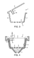
Figure 3 is a schematic profile cut view of an alternative construction of the first embodiment of the invention illustrated infigures 1 and 2 ; -
Figure 4 is a schematic profile cut view of a second embodiment of a capsule according to the invention, used with a cup-shaped capsule holder; -
Figure 5 is a schematic view similar tofigure 3 , wherein the capsule is used with a ring shaped capsule holder; -
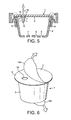
Figure 6 is a schematic perspective view of a capsule with peelable closing membranes; -
Figure 7 is yet a schematic cut view of another embodiment of the invention. - In the following detailed description, the example given is that of a machine - not represented in the drawing - with capsules for preparing beverages, typically coffee. Said machine comprises a fluid injection needle supported by an injection plate, for injection of a single jet of fluid inside the capsule, said needle being adapted in shape and size to protrude inside the capsule when said capsule holder is inserted into the machine in order for operation. Such a machine was described for instance in prior European patent
EP 1967069 B1 . According to the invention, the outer surface of the capsule top wall is in contact, at least partially, with the needle plate of the machine, during the dissolution/extraction step. -
Figure 1 shows a first embodiment of acapsule 1 according to the invention, wherein the capsule body is cup-shaped, withside walls 2, atop wall 3, and abottom wall 4 that is pierced with a plurality of dispensingholes 5 for the product produced inside the capsule chamber to flow out. Thecapsule top wall 3 is rigid, the outer surface of the rigid top wall is covered during storage by a removable lid, which can be a glued or sealed foil, or a semi-rigid lid clipped thereonto - not shown on the drawing -. - The
capsule 1 is placed in acapsule holder 6, to which a supportinginsert 7 can be added in order to support thebottom wall 4 of the capsule. Such aninsert 7 can be necessary to prevent damage to the capsule wall, particularly when the capsule contains such products like roast and ground powdered coffee, which requires high fluid pressure inside the capsule chamber to prepare the final product, for instance espresso coffee. In this case, if the capsule that is loaded into the capsule holder does not fit properly the internal shape and size of the capsule holder, when fluid pressure inside the capsule holder increases, the portion of the capsule wall that is not supported by the capsule holder walls can be pushed outwardly, and even can be pierced, which is of course highly undesirable. - The
insert 7 also has another important effect: in the case shown infigure 1 , the said insert 7 counterbalances the flow of product that flushes out of the capsule dispensingholes 5. By doing this, theinsert 7 contributes to keeping a high pressure inside the capsule chamber, while allowing the product by high pressure extraction to flow out. - Such an insert is not necessary in case the ingredient contained inside the capsule is meant to be dissolved or brewed at a low pressure, for instance in the case of soluble milk, tea, soup, soluble coffee, or roast and ground powdered coffee beans to be brewed at low pressure to produce "filter coffee"-like product.
- As illustrated in
figure 1 , thecapsule 1 comprises a top circumferential edge 8 disposed at the upper portion of theside walls 2, such that when said capsule is loaded in thecapsule holder 6 and said capsule holder is placed in the machine in order for operation, the interface between the needle plate, thecapsule holder 6, and the capsule edge 8 is leaktight so that fluid injected through theneedle 9 can flow only through said capsule. More precisely, thetop wall 3 is sealed onto said circumferential edges 8. - As illustrated in
figure 1 , thetop wall 3 comprises built-in showering means. The showering means 10 is a portion protruding downwards inside the capsule chamber that is built-in with the rigidtop wall 3, which comprises a plurality of showering holes having each a diameter which is inferior to the output diameter of thefluid injection needle 9. The showering means 10 is able to accommodate theneedle 9 without being pierced by said needle, and it transforms the single jet of fluid from saidneedle 9 into a plurality of jets - indicated with arrows in the drawing - directed towards the inside of the capsule chamber. - The
top wall 3 can be made of any suitable material such as coated cardboard, metal, plastic, rigid laminated film, or a combination thereof, but preferably, it is made by injection of a thermoplastic such as polyethylene or polypropylene. -
Figure 2 shows a variant of the embodiment described above in reference tofigure 1 . In this case, thecapsule 1 is supported by a ring-shapedcapsule holder 6. As described above, the interface between the needle plate, thecapsule holder 6, and the capsule edge 8 is leaktight so that fluid injected through theneedle 9 can flow only through said capsule. - In this case, it can be seen that no insert supports the
bottom wall 4 of thecapsule 1, nor does an insert support theside walls 2. Along with the explanations given above, the capsule shown infigure 2 is therefore meant for a low pressure preparation of a food product. - Turning now to
figure 3 , one can see another variant of the embodiment described above in reference tofigures 1 and 2 . In this case, thetop wall 3 is pivotally attached to thecapsule side walls 2 via a pivot hinge 12. More precisely, the hinge is disposed between thetop wall 3 and the circumferential edge 8. In this case, the capsulebottom wall 4,side walls 2, the hinge 12, and thetop wall 3 are manufactured as a single piece by injection molding of a thermoplastic material. -
Figure 4 shows a second embodiment of the invention, wherein thetop wall 3 of thecapsule 1 is a flexible film. The saidfilm 3 is a multilayer film comprising on the outside a continuous,pierceable layer 13, and theinner layer 14 comprises a deformable layer that is pierced with a plurality of showering holes 11. When theneedle 9 presses onto the capsuletop wall 3, thefirst layer 13 of thetop wall 3 is pierced by the needle which passes through and contacts thebottom deformable layer 14. Both layers 13, 14 of the top wall delaminate as illustrated infigures 4 or5 , such that thedeformable layer 14 accommodates the needle shape and size without being pierced through. When fluid is injected through the needle, the fluid occupies thespace 15 comprised between the twolayers deformable layer 14. - At that time, the fluid shower jets that are created inside the capsule have a reduced speed compared to the speed of the fluid jet initially coming out of the needle.
-
Figure 5 shows a variant of the embodiment described above in reference tofigure 4 . In this case, thecapsule 1 is supported by a ring-shapedcapsule holder 6. As described above, the interface between the needle plate, thecapsule holder 6, and the capsule edge 8 is leaktight so that fluid injected through theneedle 9 can flow only through said capsule. - In this case, it can be seen that no insert supports the
bottom wall 4 of thecapsule 1, nor does an insert support theside walls 2. Along with the explanations given above, the capsule shown infigure 5 is therefore meant for a low pressure preparation of a food product. - As illustrated in
figure 6 , the capsule according to the present invention can be manufactured so that thetop wall 3, including the showering means 10, is covered with apeelable film layer 16a sealed onto the circumferential edges 8 of the capsule body. Similarly, thebottom wall 4 can be covered by apeelable film layer 16b, which is sealed onto the circumferential edge of the said bottom wall. Suchpeelable layers figures 1, 2 , or3 . -
Figure 7 illustrates yet another embodiment of the invention, which is a variant of the embodiment described above with reference tofigure 1 . In the present case, the showeringprotrusion 10 protrudes downwards into the capsule chamber, but its shape is angled so that its distal end extends horizontally across the internal cross-section of the capsule chamber. As can be seen fromfigure 7 , the fluid flow output - marked in the drawing with a series of small arrows - is therefore more even throughout the capsule chamber. Different shapes for the distal end of the showering meansprotrusion 10 could be envisaged, following the principle of an even distribution of the fluid flow path. - In all embodiments and variants described herein above, the interface between the portion of the needle plate that carries the
needle 9, and thetop wall 3 of thecapsule 1, is leaktight. In this case, the portion of the needle plate surrounding the needle has preferably a shape as described for instance in prior European patentEP 1967099 B1 , so as to create a leak-tightness at least locally around the injection point between theneedle 9 and thetop wall 3. - Alternatively to the leak-tightness achieved locally around the injection point, the sealing can be realised at the interface between the capsule holder upper edge, the capsule circumferential edge 8, and the surroundings of the needle plate, as illustrated by dotted-line circles in
figure 5 . - In order to guarantee the freshness of the ingredient contained therein, the capsule must be closed during storage, and open only at the time it is used with machine. In a first possibility the capsule itself is open at the top and/or the bottom sides, as represented in
figures 1 to 5 . The tightness during storage is guaranteed by a secondary packaging such as a flowpack - not shown in the drawing. - Alternatively, the capsule itself is preferably closed, so as to avoid the need for a secondary packaging while guaranteeing the freshness of the product contained inside during long storage periods. In this case, as illustrated in
figure 6 , the capsule open walls, can be covered with peelable film membrane, which are preferably made of a material barrier to gas and light. The peelable film membranes can be heat sealed, ultrasonically sealed, glued or attached by any other means which provide a tight sealing while allowing a consumer to easily peel them off. In an alternative embodiment - not shown in the drawing -, the peelable film membranes are replaced by rigid or flexible lids which are clipped to the capsule walls. - The capsule according to the present invention is suitable for high or low pressure extraction of the ingredient(s) contained therein. In case the contents is coffee, the capsule of the invention can be used for high pressure extraction of roast and ground powdered coffee beans, or for low pressure dissolution of soluble powdered coffee. The conception of the capsule, independent from the essential features disclosed and claimed in the present patent specification, can be adapted according to the necessary features for high or low pressure use, which the skilled person will be able to choose appropriately. If needed, an insert as described above can be used to guarantee that a high pressure inside the capsule will not damage it.
- It should be understood that various changes and modifications to the presently preferred embodiments described herein will be apparent to those skilled in the art. Such changes and modifications can be made without departing from the scope of the present invention and without diminishing its attendant advantages. It is therefore intended that such changes and modifications be covered by the appended claims.
Claims (5)
- A capsule (1) for use with a food preparation machine, wherein:- said machine comprises a fluid injection needle (9) supported by an injection plate, for injection of a single jet of fluid inside the capsule, said needle (9) being adapted in shape and size to protrude inside the capsule (1) when said capsule is inserted into the machine in order for operation, and- said capsule comprises a body with side (2), bottom (4) and top (3) walls defining a chamber wherein a food ingredient is contained which is to be extracted and/or dissolved by the fluid injected in said chamber through said top wall (3), said capsule further comprising a top circumferential edge (8) such that when said capsule (1) is placed in the machine in order for operation, the interface between the needle plate, and the capsule edge (8) is leaktight so that fluid can flow from the injection means only through said capsule, and- the capsule top wall (3) is sealed onto said circumferential edge (8),
characterized in that the capsule top wall (3) comprises built-in showering means (10) comprising at least one opening (11) so as to accommodate the needle (9) without piercing of said showering means (10), and transform the single jet of fluid from said needle into at least one jet directed towards the inside of the capsule chamber. - A capsule (1) according to any of the preceding claims, wherein the showering means (10) comprises a plurality of showering holes (11) having each a diameter which is inferior to the output diameter of the needle (9).
- A capsule (1) according to any of the preceding claims 1 or 2, wherein the top wall (3) is rigid and the showering means (10) comprise a built-in portion protruding downwards inside the capsule chamber.
- A capsule (1) according to claim 3, wherein the top wall (3) is pivotally attached to the capsule side walls (2) via a pivot hinge (12).
- A capsule (1) according to any of the preceding claims 1 or 2, wherein the top wall (3) is a flexible film sealed onto the circumferential edges (8) of the capsule body, said top wall (3) comprising at least one layer (14) of a pre-pierced film that is flexible enough to deform without piercing when in contact with the injection needle.
Priority Applications (2)
| Application Number | Priority Date | Filing Date | Title |
|---|---|---|---|
| PL10768260T PL2590876T3 (en) | 2010-07-07 | 2010-10-25 | A capsule for preparation of a food product from a food preparation machine |
| EP10768260.1A EP2590876B2 (en) | 2010-07-07 | 2010-10-25 | A capsule for preparation of a food product from a food preparation machine |
Applications Claiming Priority (3)
| Application Number | Priority Date | Filing Date | Title |
|---|---|---|---|
| EP10168664A EP2404844B1 (en) | 2010-07-07 | 2010-07-07 | A capsule for preparation of a food product from a food preparation machine |
| PCT/EP2010/066067 WO2012003891A1 (en) | 2010-07-07 | 2010-10-25 | A capsule for preparation of a food product from a food preparation machine |
| EP10768260.1A EP2590876B2 (en) | 2010-07-07 | 2010-10-25 | A capsule for preparation of a food product from a food preparation machine |
Publications (3)
| Publication Number | Publication Date |
|---|---|
| EP2590876A1 EP2590876A1 (en) | 2013-05-15 |
| EP2590876B1 true EP2590876B1 (en) | 2014-12-03 |
| EP2590876B2 EP2590876B2 (en) | 2018-08-22 |
Family
ID=42831593
Family Applications (2)
| Application Number | Title | Priority Date | Filing Date |
|---|---|---|---|
| EP10168664A Not-in-force EP2404844B1 (en) | 2010-07-07 | 2010-07-07 | A capsule for preparation of a food product from a food preparation machine |
| EP10768260.1A Not-in-force EP2590876B2 (en) | 2010-07-07 | 2010-10-25 | A capsule for preparation of a food product from a food preparation machine |
Family Applications Before (1)
| Application Number | Title | Priority Date | Filing Date |
|---|---|---|---|
| EP10168664A Not-in-force EP2404844B1 (en) | 2010-07-07 | 2010-07-07 | A capsule for preparation of a food product from a food preparation machine |
Country Status (26)
| Country | Link |
|---|---|
| US (1) | US9023412B2 (en) |
| EP (2) | EP2404844B1 (en) |
| JP (1) | JP5735642B2 (en) |
| KR (1) | KR101752031B1 (en) |
| CN (1) | CN102985339B (en) |
| AR (1) | AR078836A1 (en) |
| AU (1) | AU2010357027B2 (en) |
| BR (1) | BR112013000269A2 (en) |
| CA (1) | CA2804461C (en) |
| CL (1) | CL2013000049A1 (en) |
| DK (2) | DK2404844T3 (en) |
| ES (2) | ES2395513T3 (en) |
| HK (1) | HK1166046A1 (en) |
| HR (1) | HRP20120831T1 (en) |
| HU (1) | HUE024492T2 (en) |
| IL (1) | IL223615A (en) |
| MX (1) | MX2013000180A (en) |
| MY (1) | MY164234A (en) |
| PL (2) | PL2404844T3 (en) |
| PT (2) | PT2404844E (en) |
| RU (1) | RU2533706C2 (en) |
| SG (1) | SG186358A1 (en) |
| SI (1) | SI2404844T1 (en) |
| UA (1) | UA105712C2 (en) |
| WO (1) | WO2012003891A1 (en) |
| ZA (1) | ZA201301002B (en) |
Families Citing this family (39)
| Publication number | Priority date | Publication date | Assignee | Title |
|---|---|---|---|---|
| US11832755B2 (en) * | 2007-07-13 | 2023-12-05 | Adrian Rivera | Brewing material container for a beverage brewer |
| US10722066B2 (en) * | 2010-12-04 | 2020-07-28 | Adrian Rivera | Windowed single serving brewing material holder |
| EP3521210B1 (en) * | 2010-07-22 | 2020-01-08 | K-fee System GmbH | Portion capsule with barcode |
| GB2488799A (en) | 2011-03-08 | 2012-09-12 | Kraft Foods R & D Inc | Drinks Pod without Piercing of Outer Shell |
| USD694620S1 (en) | 2011-03-08 | 2013-12-03 | Kraft Foods R&D, Inc. | Beverage cartridge |
| GB2489409B (en) | 2011-03-23 | 2013-05-15 | Kraft Foods R & D Inc | A capsule and a system for, and a method of, preparing a beverage |
| ES2429638B1 (en) * | 2012-05-11 | 2014-09-10 | Francisco NAVARRO ALCÁNTARA | Container for the preparation of a beverage under pressure of a fluid |
| USD708057S1 (en) | 2012-09-10 | 2014-07-01 | Kraft Foods R & D, Inc. | Beverage cartridge |
| USD697797S1 (en) | 2012-09-12 | 2014-01-21 | Kraft Foods R&D, Inc. | Beverage cartridge |
| WO2014097203A1 (en) * | 2012-12-21 | 2014-06-26 | Psr Profitable Strategic Redeployment Sàrl | Capsule for preparing a beverage |
| US9493297B2 (en) * | 2012-12-27 | 2016-11-15 | Sarong Societa' Per Azioni | Capsule for beverages |
| US9221204B2 (en) * | 2013-03-14 | 2015-12-29 | Kortec, Inc. | Techniques to mold parts with injection-formed aperture in gate area |
| US9902556B2 (en) * | 2013-07-10 | 2018-02-27 | Nestec S.A. | Capsule for beverage preparation |
| ES2657162T5 (en) * | 2013-12-03 | 2021-10-19 | Biserkon Holdings Ltd | Capsule and device for preparing drinks and procedure for producing capsules |
| US10450131B2 (en) | 2014-10-01 | 2019-10-22 | Kraft Foods Group Brands Llc | Coffee pod |
| USD757536S1 (en) | 2014-10-01 | 2016-05-31 | Kraft Foods Group Brands Llc | Container |
| ES2570877B1 (en) * | 2014-11-17 | 2017-03-03 | Bonesil Expansion, S.L. | Procedure of elaboration and conservation of olive paste |
| US20160159564A1 (en) * | 2014-12-09 | 2016-06-09 | Diana Smith | Single-Serve Beverage Container |
| US10111554B2 (en) | 2015-03-20 | 2018-10-30 | Meltz, LLC | Systems for and methods of controlled liquid food or beverage product creation |
| US10314320B2 (en) | 2015-03-20 | 2019-06-11 | Meltz, LLC | Systems for controlled liquid food or beverage product creation |
| US9487348B2 (en) | 2015-03-20 | 2016-11-08 | Meltz, LLC | Systems for and methods of providing support for displaceable frozen contents in beverage and food receptacles |
| US9346611B1 (en) | 2015-03-20 | 2016-05-24 | Meltz, LLC | Apparatus and processes for creating a consumable liquid food or beverage product from frozen contents |
| ITUB20154972A1 (en) * | 2015-10-19 | 2017-04-19 | Aroma System Srl | CAPSUEL TO PRODUCE DRINKS AND A CAPSULE PRODUCTION METHOD TO PRODUCE DRINKS |
| US10457431B2 (en) * | 2016-01-25 | 2019-10-29 | Darryl Ingvard Jensen | Coffee pod point of sale fabrication device |
| CA3041722A1 (en) | 2016-11-09 | 2018-05-17 | Pepsico, Inc. | Carbonated beverage makers, methods, and systems |
| US20190337713A1 (en) * | 2016-12-30 | 2019-11-07 | Whirlpool Corporation | Single-serving self-piercing pod for liquid and powdered and granular beverage concentrates |
| BR112019019085B1 (en) * | 2017-03-17 | 2024-01-09 | Caffitaly System S.P.A. | CAPSULE FOR PREPARING DRINKS |
| IT201700029991A1 (en) | 2017-03-17 | 2018-09-17 | Caffitaly System Spa | CAPSULE FOR THE PREPARATION OF A BEVERAGE |
| WO2018200922A1 (en) | 2017-04-27 | 2018-11-01 | Meltz, LLC | Method for centrifugal extraction and apparatus suitable for carrying out this method |
| CN107087987B (en) * | 2017-05-19 | 2020-07-14 | 深圳鼎加弘思饮品科技有限公司 | External piercing extraction structure for preventing liquid leakage and brewing method thereof |
| EP3470350A1 (en) * | 2017-10-16 | 2019-04-17 | Tchibo GmbH | Portion capsule |
| CA3081772C (en) * | 2018-04-23 | 2020-10-20 | 2266170 Ontario Inc. | Capsules, beverage brewing systems and fabrics with optimum filtration characteristics |
| CN108392077A (en) * | 2018-04-28 | 2018-08-14 | 广东亿龙电器科技有限公司 | A kind of capsule type coffee machine brewing mechanism |
| JP2022506862A (en) * | 2018-11-08 | 2022-01-17 | ソシエテ・デ・プロデュイ・ネスレ・エス・アー | Semi-rigid sachet for beverage preparation |
| NL2022269B1 (en) * | 2018-12-20 | 2020-07-15 | Douwe Egberts Bv | System for preparing a beverage from a capsule using a fluid supplied under pressure into the capsule and a capsule for use in such a system |
| US11724849B2 (en) | 2019-06-07 | 2023-08-15 | Cometeer, Inc. | Packaging and method for single serve beverage product |
| CN111642974B (en) * | 2020-05-21 | 2021-11-02 | 四川虹美智能科技有限公司 | Tea brewing device |
| US11805934B1 (en) * | 2020-10-21 | 2023-11-07 | Adrian Rivera | Brewing material lid and container for a beverage brewer |
| KR102480315B1 (en) * | 2021-07-08 | 2022-12-21 | 이희환 | Sealed container using environment-friendly pulp material and manufacturing method thereof |
Family Cites Families (14)
| Publication number | Priority date | Publication date | Assignee | Title |
|---|---|---|---|---|
| DE10211327B4 (en) * | 2002-03-14 | 2015-09-24 | Caffitaly System S.P.A. | Portion capsule with a particulate extractable by water substance for the preparation of a beverage |
| EP1510158A1 (en) * | 2003-08-25 | 2005-03-02 | Nestec S.A. | Apparatus and method for the preparation of a beverage from an ingredient contained in a cartridge |
| EP1510159A1 (en) * | 2003-08-25 | 2005-03-02 | Nestec S.A. | Procedure for making a food product |
| CN104528167A (en) † | 2004-08-23 | 2015-04-22 | 雀巢技术公司 | Capsule for preparing and delivering a drink by injecting a pressurized fluid into the capsule |
| US20060065127A1 (en) † | 2004-09-24 | 2006-03-30 | Dalton David A | Liquid infusion pods containing insoluble materials |
| DE102004056224A1 (en) | 2004-11-19 | 2006-05-24 | Tchibo Gmbh | System with a coffee maker and a portion capsule |
| DE102004056317A1 (en) | 2004-11-22 | 2006-05-24 | Schifferle, René | Beverage machine for producing a hot beverage by brewing and extracting substances packaged in a capsule |
| DE102005058336A1 (en) * | 2005-12-02 | 2007-06-06 | Tchibo Gmbh | portion capsule |
| US20070186779A1 (en) * | 2006-02-15 | 2007-08-16 | Fung Kam F | Re-usable beverage maker filter container and method of use |
| DE602006014498D1 (en) * | 2006-02-27 | 2010-07-08 | Nestec Sa | Capsule with beverage preparation with integral element for all-round deflection of the infusion pressure jet |
| ES2336036T3 (en) | 2007-03-06 | 2010-04-07 | Nestec S.A. | DEVICE FOR THE PREPARATION OF A FOOD LIQUID FROM A CAPSULE. |
| EP1967069B1 (en) | 2007-03-08 | 2011-05-11 | Soremartec S.A. | Wafer sheet, corresponding production plate and method of use |
| ATE536775T1 (en) † | 2008-02-29 | 2011-12-15 | Nestec Sa | METHOD AND SYSTEM FOR PREPARING A LIQUID EXTRACT FROM A CELL USING CENTRIFUGAL FORCES |
| CN201160776Y (en) * | 2008-03-14 | 2008-12-10 | 刘志洪 | Safety coffee powder package preparing apparatus of coffee machine |
-
2010
- 2010-07-07 PL PL10168664T patent/PL2404844T3/en unknown
- 2010-07-07 SI SI201030080T patent/SI2404844T1/en unknown
- 2010-07-07 PT PT10168664T patent/PT2404844E/en unknown
- 2010-07-07 DK DK10168664.0T patent/DK2404844T3/en active
- 2010-07-07 EP EP10168664A patent/EP2404844B1/en not_active Not-in-force
- 2010-07-07 ES ES10168664T patent/ES2395513T3/en active Active
- 2010-10-25 EP EP10768260.1A patent/EP2590876B2/en not_active Not-in-force
- 2010-10-25 MX MX2013000180A patent/MX2013000180A/en active IP Right Grant
- 2010-10-25 JP JP2013517042A patent/JP5735642B2/en not_active Expired - Fee Related
- 2010-10-25 KR KR1020137003192A patent/KR101752031B1/en active IP Right Grant
- 2010-10-25 PT PT107682601T patent/PT2590876E/en unknown
- 2010-10-25 US US13/808,785 patent/US9023412B2/en active Active
- 2010-10-25 MY MYPI2012701141A patent/MY164234A/en unknown
- 2010-10-25 BR BR112013000269A patent/BR112013000269A2/en not_active IP Right Cessation
- 2010-10-25 AU AU2010357027A patent/AU2010357027B2/en not_active Ceased
- 2010-10-25 ES ES10768260.1T patent/ES2528767T3/en active Active
- 2010-10-25 CA CA2804461A patent/CA2804461C/en not_active Expired - Fee Related
- 2010-10-25 SG SG2012092227A patent/SG186358A1/en unknown
- 2010-10-25 RU RU2013105011/12A patent/RU2533706C2/en not_active IP Right Cessation
- 2010-10-25 PL PL10768260T patent/PL2590876T3/en unknown
- 2010-10-25 WO PCT/EP2010/066067 patent/WO2012003891A1/en active Application Filing
- 2010-10-25 HU HUE10768260A patent/HUE024492T2/en unknown
- 2010-10-25 UA UAA201301380A patent/UA105712C2/en unknown
- 2010-10-25 CN CN201080067932.8A patent/CN102985339B/en not_active Expired - Fee Related
- 2010-10-25 DK DK10768260.1T patent/DK2590876T3/en active
- 2010-10-29 AR ARP100104002A patent/AR078836A1/en not_active Application Discontinuation
-
2012
- 2012-07-10 HK HK12106743.3A patent/HK1166046A1/en not_active IP Right Cessation
- 2012-10-15 HR HRP20120831AT patent/HRP20120831T1/en unknown
- 2012-12-13 IL IL223615A patent/IL223615A/en not_active IP Right Cessation
-
2013
- 2013-01-07 CL CL2013000049A patent/CL2013000049A1/en unknown
- 2013-02-06 ZA ZA2013/01002A patent/ZA201301002B/en unknown
Also Published As
Similar Documents
| Publication | Publication Date | Title |
|---|---|---|
| EP2590876B1 (en) | A capsule for preparation of a food product from a food preparation machine | |
| CA2864842C (en) | Capsule for beverage | |
| AU2013357703B2 (en) | Portion capsule and method for producing a beverage by means of a portion capsule | |
| US9833103B2 (en) | Capsule-based food preparation system | |
| JP6937755B2 (en) | Beverage preparation system and capsules | |
| EP2412646A1 (en) | A capsule for food preparation | |
| EP3003910B1 (en) | A capsule for beverage preparation | |
| US20140342060A1 (en) | Capsule for beverage | |
| JP2017529130A (en) | Pack for preparing food or beverage |
Legal Events
| Date | Code | Title | Description |
|---|---|---|---|
| PUAI | Public reference made under article 153(3) epc to a published international application that has entered the european phase |
Free format text: ORIGINAL CODE: 0009012 |
|
| 17P | Request for examination filed |
Effective date: 20130207 |
|
| AK | Designated contracting states |
Kind code of ref document: A1 Designated state(s): AL AT BE BG CH CY CZ DE DK EE ES FI FR GB GR HR HU IE IS IT LI LT LU LV MC MK MT NL NO PL PT RO RS SE SI SK SM TR |
|
| DAX | Request for extension of the european patent (deleted) | ||
| REG | Reference to a national code |
Ref country code: HK Ref legal event code: DE Ref document number: 1184422 Country of ref document: HK |
|
| GRAJ | Information related to disapproval of communication of intention to grant by the applicant or resumption of examination proceedings by the epo deleted |
Free format text: ORIGINAL CODE: EPIDOSDIGR1 |
|
| GRAP | Despatch of communication of intention to grant a patent |
Free format text: ORIGINAL CODE: EPIDOSNIGR1 |
|
| INTG | Intention to grant announced |
Effective date: 20140918 |
|
| GRAS | Grant fee paid |
Free format text: ORIGINAL CODE: EPIDOSNIGR3 |
|
| GRAA | (expected) grant |
Free format text: ORIGINAL CODE: 0009210 |
|
| AK | Designated contracting states |
Kind code of ref document: B1 Designated state(s): AL AT BE BG CH CY CZ DE DK EE ES FI FR GB GR HR HU IE IS IT LI LT LU LV MC MK MT NL NO PL PT RO RS SE SI SK SM TR |
|
| REG | Reference to a national code |
Ref country code: GB Ref legal event code: FG4D |
|
| REG | Reference to a national code |
Ref country code: CH Ref legal event code: EP Ref country code: AT Ref legal event code: REF Ref document number: 699219 Country of ref document: AT Kind code of ref document: T Effective date: 20141215 |
|
| REG | Reference to a national code |
Ref country code: IE Ref legal event code: FG4D |
|
| REG | Reference to a national code |
Ref country code: DK Ref legal event code: T3 Effective date: 20150109 |
|
| REG | Reference to a national code |
Ref country code: DE Ref legal event code: R096 Ref document number: 602010020755 Country of ref document: DE Effective date: 20150115 |
|
| REG | Reference to a national code |
Ref country code: RO Ref legal event code: EPE |
|
| REG | Reference to a national code |
Ref country code: ES Ref legal event code: FG2A Ref document number: 2528767 Country of ref document: ES Kind code of ref document: T3 Effective date: 20150212 |
|
| REG | Reference to a national code |
Ref country code: PT Ref legal event code: SC4A Free format text: AVAILABILITY OF NATIONAL TRANSLATION Effective date: 20150206 |
|
| REG | Reference to a national code |
Ref country code: SE Ref legal event code: TRGR |
|
| REG | Reference to a national code |
Ref country code: NL Ref legal event code: T3 |
|
| REG | Reference to a national code |
Ref country code: SK Ref legal event code: T3 Ref document number: E 17815 Country of ref document: SK |
|
| REG | Reference to a national code |
Ref country code: GR Ref legal event code: EP Ref document number: 20150400152 Country of ref document: GR Effective date: 20150220 |
|
| PG25 | Lapsed in a contracting state [announced via postgrant information from national office to epo] |
Ref country code: LT Free format text: LAPSE BECAUSE OF FAILURE TO SUBMIT A TRANSLATION OF THE DESCRIPTION OR TO PAY THE FEE WITHIN THE PRESCRIBED TIME-LIMIT Effective date: 20141203 |
|
| REG | Reference to a national code |
Ref country code: PL Ref legal event code: T3 |
|
| REG | Reference to a national code |
Ref country code: NO Ref legal event code: T2 Effective date: 20141203 |
|
| REG | Reference to a national code |
Ref country code: LT Ref legal event code: MG4D |
|
| PG25 | Lapsed in a contracting state [announced via postgrant information from national office to epo] |
Ref country code: RS Free format text: LAPSE BECAUSE OF FAILURE TO SUBMIT A TRANSLATION OF THE DESCRIPTION OR TO PAY THE FEE WITHIN THE PRESCRIBED TIME-LIMIT Effective date: 20141203 Ref country code: HR Free format text: LAPSE BECAUSE OF FAILURE TO SUBMIT A TRANSLATION OF THE DESCRIPTION OR TO PAY THE FEE WITHIN THE PRESCRIBED TIME-LIMIT Effective date: 20141203 Ref country code: CY Free format text: LAPSE BECAUSE OF FAILURE TO SUBMIT A TRANSLATION OF THE DESCRIPTION OR TO PAY THE FEE WITHIN THE PRESCRIBED TIME-LIMIT Effective date: 20141203 Ref country code: LV Free format text: LAPSE BECAUSE OF FAILURE TO SUBMIT A TRANSLATION OF THE DESCRIPTION OR TO PAY THE FEE WITHIN THE PRESCRIBED TIME-LIMIT Effective date: 20141203 |
|
| PG25 | Lapsed in a contracting state [announced via postgrant information from national office to epo] |
Ref country code: EE Free format text: LAPSE BECAUSE OF FAILURE TO SUBMIT A TRANSLATION OF THE DESCRIPTION OR TO PAY THE FEE WITHIN THE PRESCRIBED TIME-LIMIT Effective date: 20141203 |
|
| PG25 | Lapsed in a contracting state [announced via postgrant information from national office to epo] |
Ref country code: IS Free format text: LAPSE BECAUSE OF FAILURE TO SUBMIT A TRANSLATION OF THE DESCRIPTION OR TO PAY THE FEE WITHIN THE PRESCRIBED TIME-LIMIT Effective date: 20150403 |
|
| REG | Reference to a national code |
Ref country code: DE Ref legal event code: R026 Ref document number: 602010020755 Country of ref document: DE |
|
| PLBI | Opposition filed |
Free format text: ORIGINAL CODE: 0009260 |
|
| 26 | Opposition filed |
Opponent name: BARZANO & ZANARDO Effective date: 20150903 |
|
| PLAX | Notice of opposition and request to file observation + time limit sent |
Free format text: ORIGINAL CODE: EPIDOSNOBS2 |
|
| REG | Reference to a national code |
Ref country code: HU Ref legal event code: AG4A Ref document number: E024492 Country of ref document: HU |
|
| PLBB | Reply of patent proprietor to notice(s) of opposition received |
Free format text: ORIGINAL CODE: EPIDOSNOBS3 |
|
| PG25 | Lapsed in a contracting state [announced via postgrant information from national office to epo] |
Ref country code: SI Free format text: LAPSE BECAUSE OF FAILURE TO SUBMIT A TRANSLATION OF THE DESCRIPTION OR TO PAY THE FEE WITHIN THE PRESCRIBED TIME-LIMIT Effective date: 20141203 |
|
| PG25 | Lapsed in a contracting state [announced via postgrant information from national office to epo] |
Ref country code: LU Free format text: LAPSE BECAUSE OF FAILURE TO SUBMIT A TRANSLATION OF THE DESCRIPTION OR TO PAY THE FEE WITHIN THE PRESCRIBED TIME-LIMIT Effective date: 20151025 |
|
| PG25 | Lapsed in a contracting state [announced via postgrant information from national office to epo] |
Ref country code: MC Free format text: LAPSE BECAUSE OF FAILURE TO SUBMIT A TRANSLATION OF THE DESCRIPTION OR TO PAY THE FEE WITHIN THE PRESCRIBED TIME-LIMIT Effective date: 20141203 |
|
| REG | Reference to a national code |
Ref country code: AT Ref legal event code: UEP Ref document number: 699219 Country of ref document: AT Kind code of ref document: T Effective date: 20141203 |
|
| REG | Reference to a national code |
Ref country code: FR Ref legal event code: PLFP Year of fee payment: 7 |
|
| PGFP | Annual fee paid to national office [announced via postgrant information from national office to epo] |
Ref country code: BG Payment date: 20160926 Year of fee payment: 7 |
|
| PGFP | Annual fee paid to national office [announced via postgrant information from national office to epo] |
Ref country code: PL Payment date: 20160916 Year of fee payment: 7 Ref country code: GR Payment date: 20160926 Year of fee payment: 7 Ref country code: SK Payment date: 20160913 Year of fee payment: 7 Ref country code: RO Payment date: 20160914 Year of fee payment: 7 |
|
| PGFP | Annual fee paid to national office [announced via postgrant information from national office to epo] |
Ref country code: BE Payment date: 20160913 Year of fee payment: 7 Ref country code: TR Payment date: 20160927 Year of fee payment: 7 |
|
| PGFP | Annual fee paid to national office [announced via postgrant information from national office to epo] |
Ref country code: CZ Payment date: 20161004 Year of fee payment: 7 Ref country code: DK Payment date: 20161012 Year of fee payment: 7 Ref country code: CH Payment date: 20161013 Year of fee payment: 7 Ref country code: FI Payment date: 20161010 Year of fee payment: 7 Ref country code: NO Payment date: 20161011 Year of fee payment: 7 Ref country code: HU Payment date: 20161006 Year of fee payment: 7 Ref country code: IE Payment date: 20161010 Year of fee payment: 7 Ref country code: NL Payment date: 20161010 Year of fee payment: 7 |
|
| PGFP | Annual fee paid to national office [announced via postgrant information from national office to epo] |
Ref country code: SE Payment date: 20161011 Year of fee payment: 7 Ref country code: PT Payment date: 20161025 Year of fee payment: 7 Ref country code: AT Payment date: 20160928 Year of fee payment: 7 |
|
| PG25 | Lapsed in a contracting state [announced via postgrant information from national office to epo] |
Ref country code: SM Free format text: LAPSE BECAUSE OF FAILURE TO SUBMIT A TRANSLATION OF THE DESCRIPTION OR TO PAY THE FEE WITHIN THE PRESCRIBED TIME-LIMIT Effective date: 20141203 |
|
| PG25 | Lapsed in a contracting state [announced via postgrant information from national office to epo] |
Ref country code: MT Free format text: LAPSE BECAUSE OF FAILURE TO SUBMIT A TRANSLATION OF THE DESCRIPTION OR TO PAY THE FEE WITHIN THE PRESCRIBED TIME-LIMIT Effective date: 20141203 |
|
| REG | Reference to a national code |
Ref country code: FR Ref legal event code: PLFP Year of fee payment: 8 |
|
| RAP2 | Party data changed (patent owner data changed or rights of a patent transferred) |
Owner name: NESTEC S.A. |
|
| PLAB | Opposition data, opponent's data or that of the opponent's representative modified |
Free format text: ORIGINAL CODE: 0009299OPPO |
|
| R26 | Opposition filed (corrected) |
Opponent name: BARZANO & ZANARDO Effective date: 20150903 |
|
| REG | Reference to a national code |
Ref country code: DK Ref legal event code: EBP Effective date: 20171031 |
|
| REG | Reference to a national code |
Ref country code: NO Ref legal event code: MMEP |
|
| REG | Reference to a national code |
Ref country code: SE Ref legal event code: EUG |
|
| REG | Reference to a national code |
Ref country code: CH Ref legal event code: PL |
|
| REG | Reference to a national code |
Ref country code: NL Ref legal event code: MM Effective date: 20171101 |
|
| RIN2 | Information on inventor provided after grant (corrected) |
Inventor name: DOLEAC, FREDERIC Inventor name: RAEDERER, MARC |
|
| REG | Reference to a national code |
Ref country code: AT Ref legal event code: MM01 Ref document number: 699219 Country of ref document: AT Kind code of ref document: T Effective date: 20171025 |
|
| PG25 | Lapsed in a contracting state [announced via postgrant information from national office to epo] |
Ref country code: MK Free format text: LAPSE BECAUSE OF FAILURE TO SUBMIT A TRANSLATION OF THE DESCRIPTION OR TO PAY THE FEE WITHIN THE PRESCRIBED TIME-LIMIT Effective date: 20141203 |
|
| REG | Reference to a national code |
Ref country code: SK Ref legal event code: MM4A Ref document number: E 17815 Country of ref document: SK Effective date: 20171025 |
|
| PUAH | Patent maintained in amended form |
Free format text: ORIGINAL CODE: 0009272 |
|
| STAA | Information on the status of an ep patent application or granted ep patent |
Free format text: STATUS: PATENT MAINTAINED AS AMENDED |
|
| REG | Reference to a national code |
Ref country code: IE Ref legal event code: MM4A |
|
| PG25 | Lapsed in a contracting state [announced via postgrant information from national office to epo] |
Ref country code: PT Free format text: LAPSE BECAUSE OF NON-PAYMENT OF DUE FEES Effective date: 20180426 Ref country code: CH Free format text: LAPSE BECAUSE OF NON-PAYMENT OF DUE FEES Effective date: 20171031 Ref country code: SK Free format text: LAPSE BECAUSE OF NON-PAYMENT OF DUE FEES Effective date: 20171025 Ref country code: NO Free format text: LAPSE BECAUSE OF NON-PAYMENT OF DUE FEES Effective date: 20171031 Ref country code: FI Free format text: LAPSE BECAUSE OF NON-PAYMENT OF DUE FEES Effective date: 20171025 Ref country code: CZ Free format text: LAPSE BECAUSE OF NON-PAYMENT OF DUE FEES Effective date: 20171025 Ref country code: LI Free format text: LAPSE BECAUSE OF NON-PAYMENT OF DUE FEES Effective date: 20171031 Ref country code: NL Free format text: LAPSE BECAUSE OF NON-PAYMENT OF DUE FEES Effective date: 20171101 |
|
| 27A | Patent maintained in amended form |
Effective date: 20180822 |
|
| AK | Designated contracting states |
Kind code of ref document: B2 Designated state(s): AL AT BE BG CH CY CZ DE DK EE ES FI FR GB GR HR HU IE IS IT LI LT LU LV MC MK MT NL NO PL PT RO RS SE SI SK SM TR |
|
| REG | Reference to a national code |
Ref country code: DE Ref legal event code: R102 Ref document number: 602010020755 Country of ref document: DE Ref country code: BE Ref legal event code: FP Effective date: 20150212 Ref country code: BE Ref legal event code: MM Effective date: 20171031 |
|
| PG25 | Lapsed in a contracting state [announced via postgrant information from national office to epo] |
Ref country code: RO Free format text: LAPSE BECAUSE OF NON-PAYMENT OF DUE FEES Effective date: 20171025 Ref country code: SE Free format text: LAPSE BECAUSE OF NON-PAYMENT OF DUE FEES Effective date: 20171026 Ref country code: HU Free format text: LAPSE BECAUSE OF NON-PAYMENT OF DUE FEES Effective date: 20171026 Ref country code: BE Free format text: LAPSE BECAUSE OF NON-PAYMENT OF DUE FEES Effective date: 20171031 Ref country code: AT Free format text: LAPSE BECAUSE OF NON-PAYMENT OF DUE FEES Effective date: 20171025 Ref country code: GR Free format text: LAPSE BECAUSE OF NON-PAYMENT OF DUE FEES Effective date: 20180504 |
|
| REG | Reference to a national code |
Ref country code: FR Ref legal event code: PLFP Year of fee payment: 9 |
|
| PG25 | Lapsed in a contracting state [announced via postgrant information from national office to epo] |
Ref country code: IE Free format text: LAPSE BECAUSE OF NON-PAYMENT OF DUE FEES Effective date: 20171025 Ref country code: AL Free format text: LAPSE BECAUSE OF FAILURE TO SUBMIT A TRANSLATION OF THE DESCRIPTION OR TO PAY THE FEE WITHIN THE PRESCRIBED TIME-LIMIT Effective date: 20141203 |
|
| PGFP | Annual fee paid to national office [announced via postgrant information from national office to epo] |
Ref country code: FR Payment date: 20180913 Year of fee payment: 9 |
|
| PG25 | Lapsed in a contracting state [announced via postgrant information from national office to epo] |
Ref country code: DK Free format text: LAPSE BECAUSE OF NON-PAYMENT OF DUE FEES Effective date: 20171031 |
|
| PG25 | Lapsed in a contracting state [announced via postgrant information from national office to epo] |
Ref country code: GR Free format text: LAPSE BECAUSE OF FAILURE TO SUBMIT A TRANSLATION OF THE DESCRIPTION OR TO PAY THE FEE WITHIN THE PRESCRIBED TIME-LIMIT Effective date: 20181123 Ref country code: BG Free format text: LAPSE BECAUSE OF NON-PAYMENT OF DUE FEES Effective date: 20180506 |
|
| PGFP | Annual fee paid to national office [announced via postgrant information from national office to epo] |
Ref country code: DE Payment date: 20181009 Year of fee payment: 9 |
|
| PGFP | Annual fee paid to national office [announced via postgrant information from national office to epo] |
Ref country code: ES Payment date: 20181102 Year of fee payment: 9 Ref country code: GB Payment date: 20181024 Year of fee payment: 9 Ref country code: IT Payment date: 20181018 Year of fee payment: 9 |
|
| PG25 | Lapsed in a contracting state [announced via postgrant information from national office to epo] |
Ref country code: ES Free format text: LAPSE BECAUSE OF FAILURE TO SUBMIT A TRANSLATION OF THE DESCRIPTION OR TO PAY THE FEE WITHIN THE PRESCRIBED TIME-LIMIT Effective date: 20180822 |
|
| PG25 | Lapsed in a contracting state [announced via postgrant information from national office to epo] |
Ref country code: ES Free format text: THE PATENT HAS BEEN ANNULLED BY A DECISION OF A NATIONAL AUTHORITY Effective date: 20180822 |
|
| PG25 | Lapsed in a contracting state [announced via postgrant information from national office to epo] |
Ref country code: PL Free format text: LAPSE BECAUSE OF NON-PAYMENT OF DUE FEES Effective date: 20171025 |
|
| REG | Reference to a national code |
Ref country code: DE Ref legal event code: R119 Ref document number: 602010020755 Country of ref document: DE |
|
| REG | Reference to a national code |
Ref country code: HK Ref legal event code: WD Ref document number: 1184422 Country of ref document: HK |
|
| PG25 | Lapsed in a contracting state [announced via postgrant information from national office to epo] |
Ref country code: GR Free format text: LAPSE BECAUSE OF FAILURE TO SUBMIT A TRANSLATION OF THE DESCRIPTION OR TO PAY THE FEE WITHIN THE PRESCRIBED TIME-LIMIT Effective date: 20180504 |
|
| PG25 | Lapsed in a contracting state [announced via postgrant information from national office to epo] |
Ref country code: DE Free format text: LAPSE BECAUSE OF NON-PAYMENT OF DUE FEES Effective date: 20200501 |
|
| GBPC | Gb: european patent ceased through non-payment of renewal fee |
Effective date: 20191025 |
|
| PG25 | Lapsed in a contracting state [announced via postgrant information from national office to epo] |
Ref country code: IT Free format text: LAPSE BECAUSE OF NON-PAYMENT OF DUE FEES Effective date: 20191025 Ref country code: GB Free format text: LAPSE BECAUSE OF NON-PAYMENT OF DUE FEES Effective date: 20191025 Ref country code: FR Free format text: LAPSE BECAUSE OF NON-PAYMENT OF DUE FEES Effective date: 20191031 |
|
| PG25 | Lapsed in a contracting state [announced via postgrant information from national office to epo] |
Ref country code: TR Free format text: LAPSE BECAUSE OF NON-PAYMENT OF DUE FEES Effective date: 20171025 |