EP2589987A1 - Location device - Google Patents
Location device Download PDFInfo
- Publication number
- EP2589987A1 EP2589987A1 EP11188062.1A EP11188062A EP2589987A1 EP 2589987 A1 EP2589987 A1 EP 2589987A1 EP 11188062 A EP11188062 A EP 11188062A EP 2589987 A1 EP2589987 A1 EP 2589987A1
- Authority
- EP
- European Patent Office
- Prior art keywords
- locating device
- push
- locating
- housing
- electromagnetic
- Prior art date
- Legal status (The legal status is an assumption and is not a legal conclusion. Google has not performed a legal analysis and makes no representation as to the accuracy of the status listed.)
- Withdrawn
Links
Images

Classifications
-
- G—PHYSICS
- G01—MEASURING; TESTING
- G01R—MEASURING ELECTRIC VARIABLES; MEASURING MAGNETIC VARIABLES
- G01R27/00—Arrangements for measuring resistance, reactance, impedance, or electric characteristics derived therefrom
- G01R27/02—Measuring real or complex resistance, reactance, impedance, or other two-pole characteristics derived therefrom, e.g. time constant
- G01R27/04—Measuring real or complex resistance, reactance, impedance, or other two-pole characteristics derived therefrom, e.g. time constant in circuits having distributed constants, e.g. having very long conductors or involving high frequencies
-
- G—PHYSICS
- G01—MEASURING; TESTING
- G01R—MEASURING ELECTRIC VARIABLES; MEASURING MAGNETIC VARIABLES
- G01R11/00—Electromechanical arrangements for measuring time integral of electric power or current, e.g. of consumption
- G01R11/02—Constructional details
- G01R11/06—Magnetic circuits of induction meters
-
- G—PHYSICS
- G01—MEASURING; TESTING
- G01V—GEOPHYSICS; GRAVITATIONAL MEASUREMENTS; DETECTING MASSES OR OBJECTS; TAGS
- G01V3/00—Electric or magnetic prospecting or detecting; Measuring magnetic field characteristics of the earth, e.g. declination, deviation
- G01V3/08—Electric or magnetic prospecting or detecting; Measuring magnetic field characteristics of the earth, e.g. declination, deviation operating with magnetic or electric fields produced or modified by objects or geological structures or by detecting devices
- G01V3/10—Electric or magnetic prospecting or detecting; Measuring magnetic field characteristics of the earth, e.g. declination, deviation operating with magnetic or electric fields produced or modified by objects or geological structures or by detecting devices using induction coils
Definitions
- the invention relates to a locating device.
- the invention relates to a locating device with the features of claim 1 for the detection of an object enclosed in a medium
- the hidden in the wall object may be, for example, a water, electricity or gas line, which should not be damaged when processing the wall.
- the object may also be a wooden beam or other supporting structure, and the machining should take place in the area of the supporting structure.
- a magnetic field is usually generated and it is checked whether the object affects the magnetic field. If the influence exceeds a predetermined level, the object is detected.
- a non-metallic article such as a wooden beam, can be detected by its dielectric properties. For this purpose, an electric field is generated and checks to what extent the object affects the electric field. The object is detected when the influence exceeds a predetermined level. If the object is a current or voltage-carrying conductor, an electromagnetic field can also be detected which surrounds the conductor. Items that are neither metallic nor have readily detectable dielectric properties, such as a plastic-coated copper power line, can be detected in this manner.
- a fundamental problem with tracking devices is that they tend to erroneous readings as detection sensitivity increases.
- the locating devices must therefore be calibrated by a user in the area of the measuring location. The calibration can make the measuring process complex and ambiguous.
- the invention has for its object to provide a sensitive locating device with ease of use.
- An inventive locating device for detecting an object, in particular an object enclosed in a medium comprises a push-pull measuring bridge for driving a first and / or a second electromagnetic device.
- Such push-pull bridge is for example in the DE 10 2010 028 723 A1 or the DE 10 2010 031 147 A1 for an inductive electromagnetic device.
- the DE 10 2010 028 718 A1 shows such a push-pull bridge for a capacitive electromagnetic device.
- Such a push-pull measuring bridge has an oscillator for supplying the capacitive electrodes (in the case of the capacitive electromagnetic device) or the coils (in the case of the inductive electromagnetic device) with phase-shifted alternating voltages.
- such push-pull measuring bridge has a control device for controlling amplitudes of at least one of these alternating voltages.
- the transmitting coils are subjected to alternating voltages, so that an alternating voltage component which is isochronous relative to the alternating voltages and which is detected, for example, by means of a receiving coil, i. is induced in this is minimized in terms of amount.
- in the inductive electromagnetic device can also be dispensed with a receiving coil and measured to the alternating voltages isochronous AC voltage component, the differential voltage measured and minimized in amount.
- a device of two ohmic resistors connected in series which may each be part of the complex resistance of the transmitting coil.
- the capacitance device ie the capacitive electrodes
- the control device is configured to amplify the alternating voltages in such a way that an AC component that is isochronous relative to the alternating voltages is minimized.
- the AC voltage component for example, by means of a potential probe, according to the in FIG. 1 of the DE 10 2010 028718 A1 be measured arrangement shown
- the first electromagnetic device generates an electromagnetic alternating field in the region of the object as a function of the drive.
- a comparator of the locator detects the object if the variable ratio differs from a predetermined ratio by more than a predetermined amount.
- the push-pull measuring bridge is, as already stated, basically known from other applications in the prior art, for example also from US Pat DE 10 2008 005 783 A1 however, does not disclose a locating device for detecting objects enclosed in a medium.
- push-pull measuring bridge By means of such push-pull measuring bridge can be measured field-compensated, so that a large measuring range with a high sensitivity of the locating device can be compatible. Furthermore, it is possible to measure differentially by means of the push-pull measuring bridge so that calibration by a user of the locating device can be dispensed with.
- the push-pull bridge may be used to alternatively measure by means of a magnetic or an electric field. The other component of the electromagnetic field goes to zero.
- a push-pull measuring bridge for selectively activating a first electrical device and / or a first electrical device by means of a changeover switch.
- the first electrical device in this case comprises at least two coils, in particular transmitting coils and serves as an inductive sensor, which makes it possible, for example, to detect metallic objects.
- the second electrical device in this case comprises at least two capacitive electrodes, and serves as a capacitive sensor, which makes it possible, for example, to detect dielectric objects.
- control device designed as push-pull measuring bridge is designed in the form of an IC (Integrated Circuit), in particular in the form of an ASIC, and arranged in the housing of the device.
- IC Integrated Circuit
- the locating device has an output device, in particular in the form of a surface display, such as an LCD display, which makes it possible to output a signal indicative of the object, in particular an optical signal.
- the locating device makes it possible that the signal pointing to an object also indicates in particular which type of object (metallic, magnetic, wood, current-carrying line and the like) has been detected.
- the locating device may include means for varying the predetermined amount by a user. This allows the user to adjust the sensitivity of the locator.
- the adjustment of the predetermined amount may be performed in accordance with an amplification of control signals supplied to the first and second electromagnetic devices so that the generated electromagnetic fields are correspondingly amplified.
- the predetermined amount may be switched between a plurality of predetermined values, such as two or three values, such that the locator has different sensitivities that are easily selectable by the user.
- the locating device also has, in one embodiment, a displacement sensor for detecting a displacement of the locating device relative to the object.
- the locating device is designed, in particular, to associate a measurement result of the push-pull measuring bridge with a displacement position of the device. In this way it is possible to associate a detected object with spatial coordinates.
- a further push-pull measuring bridge is provided with a further electromagnetic device.
- This further electromagnetic device may be an inductive, a capacitive or even another sensor unit.
- This further push-pull measuring bridge can be integrated in the same IC / ASIC as the first push-pull bridge or else in a second IC / ASIC and installed in the locating device.
- At least one of the electromagnetic devices which is controlled by means of a push-pull measuring bridge, are arranged on one side of the housing of the device, in particular on the side of the housing facing away from the output device, within the housing.
- the locating device has at least one battery, in particular at least one battery in the form of a rechargeable battery, for supplying energy.
- a first electromagnetic device can successively generate a magnetic field and an electric field in the region of the object.
- the electromagnetic device may comprise a coil and an electrode, which are connected in succession to the push-pull measuring bridge.
- the push-pull measuring bridge can be constructed such that a field adjusts to a third electromagnetic device having the variable ratio with respect to the other two electromagnetic devices.
- electrical characteristics of the first and second electromagnetic devices may be compared with one another to determine the variable ratio.
- the second electromagnetic device does not generate a field, but forms an electrical load for the push-pull bridge, which forms the variable ratio with the electrical load of the first electromagnetic device.
- the locating device may comprise a device for determining an electric field of the object, wherein the detection of the object takes place successively on the basis of a push-pull measuring bridge and the device.
- the object is detected when detected by at least one of the three described approaches.
- an output device of the locating device on detection of the object output a signal indicating that was based on what kind of field the object was detected, or what type of object is.
- a first signal may indicate a measurement made by the push-pull bridge and a magnetic field, a second signal a measurement made by the push-pull bridge and an electric field, and a third signal a measurement; which was performed by means of the device for determining the electric field of the object.
- the signal may be at least one of optical and acoustic.
- An embodiment of the locating device may comprise a plurality of adjacently arranged first electromagnetic devices which are operated successively on the push-pull measuring bridge. Thereby, a detection of the object in one or two dimensions can be performed, whereby the object can be located more accurately or a limitation of the object, such as an edge, can be found more easily.
- the measurement results obtained by means of the different first electromagnetic devices are visualized by defining display regions on an optical output device, which regions are each assigned to one of the first electromagnetic devices.
- the arrangement of the display areas preferably corresponds to the arrangement of the first electromagnetic devices.
- a removal of the object from the locating device may correspond to a color change of the optical output device.
- the optical output device is simple, and thus kept cost-effective, for example in the form of a few light-emitting diodes, the color change can be used to display the measurement result more accurately with little effort, whereby multi-color LEDs or backlit LCD displays can be used.
- the optical output device more complex, for example in the form of a color-capable graphic area output such as a graphics-capable liquid crystal display, as can be represented by a false color representation, the distance of the object graphically.
- the colored presentation of the measurement results can lead to an improved operability by a user.
- the measuring surface is usually a substantially flat surface in the region of the locating device, for example a wall, in particular a lightweight wall, a ceiling or a floor.
- One of the measuring surface facing side of the locating device is usually also flat and the distance sensor monitors an at least approximate parallelism between the measuring surface and the locating device. If the locating device does not lie sufficiently flat on the measuring surface, the predetermined ratio can be adjusted in correspondence with the deviation from the parallelism in order to keep the measuring result constant. Additionally or alternatively, a warning may be issued to the user of the locating device.
- the locating device may also include a displacement sensor for detecting a displacement of the locating device relative to the object, wherein the locating device is adapted to assign a measurement result of the push-pull measuring bridge of a displacement position. This allows a user to sweep a measuring range with the locating device and thereby record a variety of measurement results, which can then be graphically displayed, for example. In one embodiment, an image detail and / or a magnification level of the graphical representation can be selected and displayed on the optical display device of the locating device.
- the locating device can comprise a further push-pull measuring bridge with a further first and a further second electromagnetic device, the first electromagnetic device of the push-pull measuring bridge generating an electromagnetic field with negligible magnetic proportion, while the first electromagnetic device of the further push-pull measuring bridge an electromagnetic field generated with negligible electrical component to detect the object simultaneously on the basis of an electric and a magnetic field.
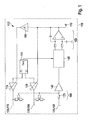
- Fig. 1 1 shows a block diagram of a push-pull bridge 100.
- the push-pull bridge 100 is part of a locating device 105 for detecting objects, in particular objects enclosed in a medium, such as a wall, a ceiling or a floor.
- the locating device - see also FIG. 5 is in particular designed as a hand-held measuring device.
- push-pull measuring bridge 100 can be used to detect a dielectric object, for example made of wood, or for detecting a metallic object, for example made of steel. In the following, the embodiment is described by means of which a dielectric object can be detected.
- a clock generator 110 has two outputs at which it provides phase-shifted, preferably 180 ° out of phase, periodic alternating signals.
- the alternating signals may in particular comprise square, triangular or sinusoidal signals.
- the outputs of the clock generator are connected to a first controllable amplifier 115 and a second controllable amplifier 120, respectively.
- Each of the controllable amplifiers 115, 120 has a control input, via which it receives a signal which controls a gain of the controllable amplifier 115, 120.
- the signals of the push-pull measuring bridge to a first electrical device 190 and / or a second electrical device 195 by means of a switch 600 (see FIG. 6 ).
- first electronic device and the second electronic device are in the FIG. 1 shown as a single unit, but with different reference numerals for the first and second device inadvertently.
- An output of the first controllable amplifier 115 is connected to a first transmitting electrode 125 and an output of the second controllable amplifier 120 is connected to a second transmitting electrode 130 of the second electronic unit 195.
- a receiving electrode 135 serves as a potential probe and is connected to an input amplifier 140; a compensation network 165 shown in the region of the electrodes 125-135 is initially not considered and an impedance 170 is omitted.
- This arrangement is referred to in the context of this application as a second electrical unit.
- the second electrical unit is, as the first electrical unit to be described - driven by the push-pull 100 - measuring bridge.
- the input amplifier 140 is shown with a constant gain factor; however, in other embodiments, an amplification factor of the input amplifier 140 may also be controllable. As a result, for example, a spatial resolution and / or sensitivity of push-pull measuring bridge 100 can be influenced and controlled, for example, as a function of a measuring signal at input amplifier 140.
- the output of the input amplifier 140 is connected to a synchronous demodulator 145.
- the synchronous demodulator 145 is further connected to the clock generator 110 connected thereto and receives from this a clock signal, which indicates the phase position of the signals provided at the outputs of the clock generator 110.
- the signals provided by the clock generator 110 are balanced square-wave signals
- one of the output signals fed to the controllable amplifiers 115, 120 can be used as a clock signal.
- the synchronous demodulator 145 alternately switches the measurement signal received from the input amplifier 140 to its upper and lower outputs based on the clock signal provided from the clock generator 110.
- the two outputs of the synchronous demodulator 145 are connected to an integrator (integrating comparator) 150, shown here as an operational amplifier connected to two resistors and two capacitors.
- integrator 150 shown here as an operational amplifier connected to two resistors and two capacitors.
- Other embodiments are also possible, for example as an active low pass.
- a digital implementation following the synchronous demodulator 145 is also conceivable, in which the signal at the outputs of the synchronous demodulator 145 is converted analog to digital at one or more times within a half-wave and then compared with the corresponding value from the next half-wave. The difference is integrated and e.g. converted back into an analog signal and used to control the amplifier 115, 120.
- the integrator 150 integrates this signal over time and provides the result at its output. While the synchronous demodulator 145 provides the measurement signal received from the input amplifier 140 at its upper output, it is integrated inversely by the integrator 150 over time and the result is provided at the output of the integrator 150.
- the voltage at the output of the integrator 150 is the integral of the difference of the low-pass filtered outputs of the synchronous demodulator 145.
- the signals provided at the outputs of the synchronous demodulator 145 have the same average over time and at the output of the integrator 150 a signal is provided goes to zero (mass).
- the capacitances are unequal, for example because a dielectric object is arranged in the region of only one of the transmitting electrodes 125, 130, then the signals provided at the outputs of the synchronous demodulator 145 are no longer equal on average, and at the output of the integrator 150 becomes a positive one or negative signal provided.
- the sign and the magnitude of the signal indicate the ratio of the capacitances, with a signal of zero corresponding to a ratio of one.
- the signal provided by the integrator 150 is provided via a connection 155 to an evaluation and output device, not shown, of the beam finder 105.
- the evaluation device can, for example, make a comparison with a threshold, so that a user of the positioning device 105 receives an optical and / or acoustic output when the signal provided by the integrator 150 exceeds a predetermined threshold. In this case, the entire signal or an amount of the signal can be compared with the threshold value.
- the signal provided by the integrator 150 is also used to control the gain factors of the controllable amplifiers 115 and 120, the second controllable amplifier 120 being directly connected to the output of the integrator 150 and the first controllable amplifier 115 being connected to the output of the integrator by means of an inverter 160 150 is connected.
- the inverter 160 effects a reversal of the signal provided to it in such a way that, as a function of the output signal of the integrator 150, the amplification factor of the first controllable amplifier 115 increases as the amplification factor of the second controllable amplifier 120 decreases or vice versa. It is also conceivable that only the amplification factor of one of the controllable amplifiers 115, 120 is controlled, while the amplification factor of the second controllable amplifier 120, 115 is kept at a fixed value.
- the amplification factors of the controllable amplifiers 115 and 120 increase or decrease until an AC component which is synchronous with the alternating voltage applied to the transmitting electrodes 125 and 130 and is applied to the receiving electrode is minimized in absolute value.
- the push-pull bridge 100 is a control circuit configured to maintain a predetermined ratio at the transmitting electrodes 125 and 130.
- the predetermined ratio is predetermined by the structure and the arrangement of the transmitting electrodes 125 and 130 to each other or to the receiving electrode 135.
- a variable ratio results from the capacitances formed at the transmitting electrodes 125 and 130 to the receiving electrode 135.
- the signal provided by integrator 150 is a control signal to compensate for asymmetric influence on the capacitances, such as through the dielectric object.
- the variable ratio at the electrodes is determined based on currents or voltages at the electrodes.
- the compensation network 165 comprises at each of the transmitting electrodes 125, 130 a voltage divider consisting of two impedances.
- the divided voltages are fed to the input amplifier 140 by means of a respective further impedance.
- the receiving electrode 135 is not directly but guided by means of the impedance 170 to the input amplifier 140.
- the illustration in FIG Fig. 1 from the compensation network 165 the impedances in the region of the first transmitting electrode 125 and the second transmitting electrode 130.
- the alternating voltages of the controllable amplifiers 115, 120 are balanced between a capacitance applied to the first (single) transmitting electrode 125 and a reference capacitance formed by the compensating network 165.
- the reference capacitance is invariant to a dielectric object. For measurement, only the first transmitting electrode 125 and the receiving electrode 135 are required.
- Compensation network 165 eliminates the impedances in the region of the second transmitting electrode 130 and the first transmitting electrode 125 is also possible.
- the push-pull bridge 100 can be used in a three-electrode measuring operation using both transmitting electrodes 125 and 130, a first two-electrode measuring operation using the first transmitting electrode 125 and the receiving electrode 135 and a second two Electrode measuring operation using the second transmitting electrode 130 and the receiving electrode 135 are operated. Switching between the different measuring operations can be cyclic or controlled by a user.
- the push-pull bridge 100 can also be used to detect a metallic object.
- a switch 600 see FIG. 6
- the voltage signals of push-pull measuring bridge 100 given to an inductive electrical device, which is referred to in this application as the first electrical unit 190.
- the push-pull measuring bridge 100 controls the first and / or the second electrical unit via the changeover switch 600. Instead of the electrodes of the second electrical E coils are used in the first electrical unit substantially. (Compare below description and explanation)
- the inductive device 190 For the description and explanation of the control of the first electrical, ie the inductive device 190 is again on FIG. 1 Referenced. In this case, the transmitting electrodes of the second electrical unit are to be replaced mentally by transmitting coils.
- the first transmitting electrode 125 is to be replaced by a first transmitting coil 175, the second transmitting electrode 130 by a second transmitting coil 180.
- the receiving electrode 135 is replaced by a single receiving coil 185 or by a system of receiving coils, preferably two receiving coils connected in series. At least one of the coils may be designed as a conductor structure on a printed circuit board ("print coil").
- the receiving electrode 135 may be formed by a single magnetoresistive magnetic field sensor, preferably a Hall effect sensor, or by a system of magnetoresistive sensors, preferably two magnetoresistive sensors connected in series Sensors, replaced.
- magnetoresistive magnetic field gradient sensors may also be used.
- the transmit coils 175, 180 generate superimposed magnetic fields with periodically varying amplitudes and phases.
- both transmit coils 175, 180 generate magnetic fields with equal amplitudes and parallel orientation of the main field directions in each half-wave of their supply voltage.
- the sign of the magnetic fields changes from half-wave to half-wave.
- the transmitting coils 175 and 180 are wound in opposite directions and their free ends connected to ground.
- the voltage supply through the controllable amplifier 115, 120 takes place with respect to ground opposite voltages.
- the transmit coils 175 and 180 in a half cycle generate magnetic fields of different amplitude and parallel or antiparallel orientation of the main field direction.
- the amplitude and the sign of the magnetic field generated by the transmitting coil 175 in a half-wave corresponds to the amplitude or the sign of the magnetic field generated by the transmitting coil 180 in the preceding or subsequent half-wave.
- the winding sense of the transmitting coils 175, 180 as well as the supply voltages of the transmitting coils 175, 180 are to be adapted accordingly to ground.
- the reception coil 185 is arranged in the region of the transmission coils 175 and 180 such that it is exposed to the superimposed magnetic field of both transmission coils 175 and 180.
- the arrangement of the coils 175 to 185 is selected such that the voltage induced in the receiving coil 185 by the magnetic fields of the transmitting coils 175 and 180 is zero, or at least constant, when the two controllable amplifiers 115 and 120 have equal amplification factors.
- the transmitting coils 175 and 180 may be coaxially arranged in two parallel planes, and the receiving coil 185 is disposed in a third parallel plane, that of the first two Each level has the same distance.
- the transmitting coils 175 and 180 may be arranged in two parallel planes.
- the two mutually connected receiving coils 185 can each be arranged in one of the two parallel planes, preferably in such a way that the orientation and position of each of the transmitting coils 175, 180 corresponds to the orientation and position of each of the receiving coils 185.
- Winding senses and interconnections of the receive coils 185 are determined from the condition that the voltage induced on the system of receive coils 185 is zero when the two controllable amplifiers 115 and 120 have equal gains. If the two transmitting coils 175, 180 in each half-wave generate magnetic fields with the same amplitude and parallel orientation of the main field direction and change the sign of the magnetic fields from half-wave to half-wave, this condition is met, for example, if the two receiving coils 185 are connected in series and wound in opposite directions. If the two receiver coils 185 are operated in antiserial series connection, then the receiver coils 185 must be wound in the same direction.
- the transmitting coils 175 and 180 are located at at least slightly axially or laterally staggered positions such that a metallic article generally occupies different distances from the transmitting coils 175 and 180.
- a stay of the object in a plane between the transmitting coils 175 and 180, in which the object in the case of axially offset transmitting coils 175, 180 equidistant from the transmitting coils 175 and 180, can be avoided by the arrangement of the transmitting coils 175 and 180 in the locating device 105 , Due to the asymmetrical position of the object with respect to the transmitting coils 175 and 180, the object is influenced differently by the magnetic fields of the transmitting coils 175 and 180.
- the magnetic fields are also through influences the metallic article differently so that the voltage induced by the superimposed magnetic fields in the receiving coil 185 is no longer zero.
- the push-pull bridge 100 compensates for this asymmetry by driving one of the amplifiers 115 and 120 to a higher amplification factor than the other of the amplifiers 115, 120 until the voltage induced by the superimposed magnetic fields in the receiver coil 185 is restored has reached zero.
- the variable ratio between the transmitting coils 175 and 180 then no longer corresponds to 1 and the terminal 155 is at a non-zero voltage. By comparing the voltage applied to the terminal 155 with the predetermined value zero (corresponding to the predetermined ratio one), the metallic object can be detected.
- FIG. 6 the schematic structure of the locating device according to the invention is shown in a preferred embodiment.
- the device has at least one push-pull bridge 100 - as described.
- a first electrical device 190 and a second electrical device 195 are provided, which can be acted upon by a change-over switch 600 of the push-pull measuring bridge 100. It is thus possible to operate two electrical devices, ie two sensors, with (only) one push-pull measuring bridge.
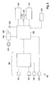
- Fig. 2 shows a schematic representation of the locating device 105 with the push-pull bridge 100 from Fig. 1 .
- the push-pull bridge 100 is advantageously integrated in an IC, for example an ASIC (application-specific IC).
- the locating device 105 comprises a processing device 205, which is connected to the push-pull measuring bridge 100. Furthermore, the processing device 205 is connected to a voltage sensor 210 and a power controller 215, which in turn is connected to a battery 220, for example a rechargeable battery and a charging socket 225. In addition, the processing device 205 is connected to a data interface 230, an optical output device 235, an acoustic output device 240, an input device 245 and a position sensor 250.
- push-pull bridge 100 is constructed separately from processing device 205.
- elements of push-pull bridge 100 may also be processed by the processing device 205 be formed.
- the switch between the first electrical device and the second electrical device may be part of the processing device 205.
- the processing device 205 is preferably a conventional digital microcomputer with a power clock generator and program and data storage.
- DAC digital-to-analog converters
- ADC analog-to-digital converter
- the processing means 205 may implement the clock generator 110, the controllable amplifiers 115 and 120, the synchronous demodulator 145, the integrator 150 and / or the inverter 160.
- the evaluation of the signal provided at the terminal 155 of the push-pull measuring bridge 105 can also take place by means of the processing device 205. This includes comparing the signal with a predetermined value and determining whether the difference between the signal and the predetermined value exceeds a predetermined level.
- the functionalities described can also be implemented by discrete components, for example by analog electronic circuits or in the form of a user-specific IC (ASIC).
- the voltage sensor 210 is a known sensor that detects an electromagnetic field generated by a live or live conductor. In one embodiment, only alternating electromagnetic fields of a predetermined frequency range are detected by the voltage sensor 210, for example in the frequency range above 20 Hz, preferably in a range of approximately 45 to 65 Hz. More preferably, the voltage sensor 210 determines the electromagnetic field due to the electrical Field applied to a measuring electrode of the voltage sensor 210 electrical voltage.
- auxiliary sensors may be connected to the processing device 210 for improving a measurement result of the push-pull measuring bridge 100.
- auxiliary sensors may be connected to the processing device 210 for improving a measurement result of the push-pull measuring bridge 100.
- sensors include, for example, a sensor which determines whether the electromagnetic devices 190 to 198 are aligned in a required manner with respect to a measuring surface, in particular, whether distances between the measuring surface and the electromagnetic devices 190 to 198 are the same. A tilting of the locating device 105 with respect to the measuring surface can be prevented.
- the measuring surface is usually the surface of a body in which the object to be detected is received.
- the body can be a wall or wall and the object hidden in it.
- the power controller 215 provides the locator 105 with voltages required for operation.
- the electrical energy required for this purpose is taken from the battery 220, for example a rechargeable battery.
- the power controller 215 may be supplied with electrical power via the charging socket 225, the power controller 215 controlling and monitoring the charging of the battery 220. Operation of the locator 105 based on electrical energy supplied exclusively via the charging socket 225 is also possible.
- the charging socket 225 is usually a low-voltage plug whose counterpart is connected to a power supply unit.
- a charging station may be provided into which the locator 105 is inserted, with the charging socket 225 electrically connected to the power supply so that the battery 220 can be charged.
- the power supply can also be included in the locating device 105 and the charging socket 225 can be connected to the usual power grid.
- Portions of the logic for powering the locator 105 and for controlling the charging of the battery 220 may be implemented by the processor 205. Further, the processing means 205 may act on the power controller 215, for example in the form of an automatic shutdown of the locator 105 after a predetermined time in which the locator 105 has not been used, or in the form of a query of a current state of charge of the battery 220.
- the processing device 205 can exchange information with an external device. Such information may relate to measurement results that have been collected or stored in a memory of the processing device 205.
- the data interface 230 and the charging socket 225 can be designed to be integrated with each other.
- the data interface 230 is a digital serial data interface, in particular a USB interface.
- the optical output device 235 comprises a number of light-emitting diodes for visualizing a measurement result of the push-pull measuring bridge 100. Further light-emitting diodes for displaying internal states of the locating device 105 can also be included, for example for indicating a state of charge of the battery.
- the optical display device 235 comprises a graphic display, such as a liquid crystal display (LCD).
- the LCD may include a backlight, such as LED or OLED, and may include a dot matrix area on which individual dots may be selectively displayed.
- Both the LCD and the backlight or light emitting diodes of the first embodiment may support multiple output colors.
- the optical output device is designed such that operation of the locating device 105 is possible both in a light and in a dark environment. For this purpose, a luminous intensity of the LED or the backlight of the LCD can be adapted to the lighting conditions in the environment.
- the acoustic output device 240 may include a speaker or a piezo-transducer.
- the representation of a measurement result of the push-pull measuring bridge 100 can be emitted visually and acoustically by means of the optical output device 235 and the acoustic output device 240 optically, acoustically or in combination.
- a position of a detected object may be displayed on the optical output device 235, while a characteristic noise from the acoustic output device 240 indicates a metallic property of the article.
- a color of the optically represented object can be symbolized at a distance, in particular a depth of the object. Associations between the color and the sound to properties of the article (metallic, dielectric, live) may be changeable, in one embodiment also by a user of the locator 105.
- the input device 245 may include a number of keys that may be combined in a keyboard. In one embodiment, the Input device 245 only a single button, with a complete operability of the locating device 105 is ensured by means of this one button.
- the input device 245 may be partially or fully backlit.
- the backlight may be coupled to a backlight of the optical output device 235. Alternatively or additionally, the backlight may be user controlled.
- the input device 245 may comprise further input means, in particular a rotary or slide controller. Such a controller may be sampled analog or digital and in particular serve for stepless or finely granular change of a parameter of the locating device 105. By means of such a regulator, a sensitivity of the push-pull measuring bridge 100 can be adjustable.
- the input device 245 may be implemented in whole or in part with the optical output device 235 in the form of a touch-sensitive screen ("touchscreen").
- the position sensor 250 serves to determine a position of the locating device 105 with respect to the measuring surface by detecting a displacement of the locating device 105 with respect to the measuring surface.
- the detection can be one-dimensional or two-dimensional.
- an acceleration sensor preferably a micromechanical acceleration sensor
- an impeller may be arranged in the region between the locating device 105 and the measuring surface, wherein a rotation of the impeller by the processing device 205 is converted into a displacement.
- a mechanism similar to that in a computer mouse may be used by holding a trackball between the locator 105 and the measurement surface, and scanning a displacement of the locator 105 based on movement of the trackball in two dimensions.
- an optical scan similar to an optical computer mouse may be performed, wherein the position sensor 250 comprises a camera facing the measurement surface, and the position sensor 250 translates the image captured by the camera into a displacement of the locator 105 the measuring surface converted.
- the conversion can also be carried out by the processing device 205.
- a light source for example in the form of one or more light-emitting diodes, can be arranged.
- push-pull measuring bridge 100 may also be included in the locating device 105 and connected to the processing device 205.
- different electromagnetic devices 190 to 198 controlled by the processing device 205, can be connectable to the one or more push-pull measuring bridges 100 so that measurements can be carried out by means of differently designed or situated electromagnetic devices 190 to 198.
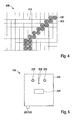
- Fig. 3 shows different arrangements of the electromagnetic devices 190 to 198 for a push-pull bridge 100 from Fig. 1
- Fig. 3A shows a matrix-like arrangement.
- the third electromagnetic element 198 forms the middle element of a 3x3 matrix whose remaining elements are formed by first and second electromagnetic devices 190, 195.
- a first electromagnetic element 190 and a second electromagnetic element 195 are opposite each other.
- Fig. 3B shows a honeycomb arrangement of electromagnetic devices 190 to 198.
- the third electromagnetic device 198 six instead of eight adjacent electromagnetic devices 190, 195 on.
- the electromagnetic devices 190, 195 comprise coils
- the in Fig. 3B shown embodiment since the coils better to the honeycomb shape than the rectangular shape in Fig. 3A approximate.
- a surface packing density of the electromagnetic devices 190 to 198 may be increased in a honeycomb arrangement.
- FIGS. 3A and 3B arrangements shown can be continued in any direction in the drawing plane.
- an arbitrarily large arrangement of electromagnetic devices 190 to 198 can in principle be supported.
- a plurality of push-pull measuring bridges 100 are provided in the locating device 105, it is also possible to carry out a plurality of measurements at the same time, it being necessary to ensure a sufficient distance between active electromagnetic devices 190 to 198 in order to avoid mutual interference.
- the electromagnetic devices 190 to 198 involved in a measurement need not adjoin one another but can be separated from one another by further, preferably non-interconnected, electromagnetic devices 190 to 198.
- FIGS. 3A and 3B shown arrangements are connected in a corresponding manner.
- Fig. 3C shows an exemplary embodiment of a combined measuring element 310 for the first and the second electrical unit.
- the combined measuring element 310 comprises a circular disk-shaped electrode 125 to 135, which is surrounded by a round coil 175 to 185. Centers of the electrodes 125-135 and the coils 175-185 coincide to detect objects having different characteristics (metallic, dielectric) with respect to the same position.
- the measuring element 310 can in the in the FIGS. 3A and 3B shown arrangements are used.
- the voltage sensor 210 may be implemented with one of the electromagnetic devices 190 to 198 integrated.
- the voltage sensor can also be arranged on a side of the electromagnetic devices 190 to 198 facing away from the measuring surface.
- Fig. 4 shows a visualization of a graphical display of the locator 105 from Fig. 2
- a graphical output 410 is divided into a number of display areas 420, 430 in a matrix-like manner.
- the display areas 420 are bright, the display areas 430 are colored dark.
- the dark colored display areas 430 represent positions where the object was detected. Instead of a subdivision into dark and light, it is also possible to use a greyscale or false color representation, wherein the gray level or color shown signals a removal of the object or a property of the object (metallic, dielectric, live).
- Each of the display areas 420, 430 corresponds to a third electromagnetic device 198 in a matrix-like arrangement as in FIG Fig. 3A ,
- the output 410 gives a visual impression of a size and location of the object to be detected.
- Fig. 4 symbolically, there are further display regions 420, 430 outside the output 410. These represent measurement results which were carried out and stored at different positions by means of the locating device 105. By moving the measuring device 105 on the measuring surface, the detail displayed on the output 410 can be shifted over these stored measured values. Different graphical processing of the stored measured values can be carried out.
- the measured values may each represent the variable ratio and a comparison with the predetermined ratio and a corresponding representation on the output 410 in light or dark can be performed "fresh" for the display areas 420, 430 in the area of the output 410.
- the predetermined ratio can be adjusted according to a user input.
- a bar graph may appear, wherein the length of a bar may correspond to a value of the variable ratio or its deviation from the predetermined ratio.
- This type of representation is particularly suitable for a one-dimensional displacement of the locating device 105 with respect to the measuring surface. Saved display areas 420, 430 beyond the output 410 then exist only in one area direction, ie either horizontally or vertically. If the locating device 105 is vertically displaceable, then the bars are preferably shown horizontally and vice versa.
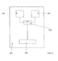
- Fig. 5 shows a view of an exemplary locating device 105.
- the locating device 105 includes an input device and an optical output device in the form of a display.
- the locating device 105 is accommodated in a housing 510.
- a handle is arranged, which, however, can also be formed on the top of the device.
- the locator 105 may be sealed to 1P54 standard.
- the representation of the measurement results i. the signaling of the detection of found objects can be visualized, for example, via a segment or dot-matrix display.
- the optical display device 235 comprises a graphic display, such as a liquid crystal display (LCD).
- the LCD may include a backlight, such as LED or OLED, and may include a dot matrix area on which individual dots may be selectively displayed.
- Both the LCD and the backlight or light emitting diodes of the first embodiment may support multiple output colors.
- the optical output device is designed such that operation of the locating device 105 is possible both in a light and in a dark environment. For this purpose, a luminous intensity of the LED or the backlight of the LCD can be adapted to the lighting conditions in the environment.
- a button 245 controls all the functions of the locating device 105. In the simplest case, only switching on and off of the locating device 105 is controlled by means of the button 245. By longer or shorter, simple and multiple keystrokes on the button 245, other functions of the locator 105 may be controlled, such as switching a sensitivity, a calibration or an output of the state of charge of the battery 220th
- buttons for example, selection buttons, whether to be measured with the first or the second electrical unit.
- the device according to the invention also has a device-internal power supply, which may be formed by batteries or even rechargeable batteries.
- the batteries can be permanently integrated in the device or can also be removed from the device for charging purposes.
- the charging electronics is integrated in the device.
- the supply of external energy is then via an interface to the housing of the device, such as a low-voltage connector or a USB socket
- a USB socket may be present as a combined data interface 230 and charging socket 225, as shown in FIG FIG. 6 is shown.
- the output unit can also enable the display of measurement results via LEDs.
- the thresholds of the individual LEDs can be generated by a controller integrated in the device or by analogue electronics. In this case, e.g. the center finding can be visualized via colored LEDs or an AC line can also be displayed.
- the LEDs 235 in the embodiment of FIG. 5 indicate a position of the object to the left or right of a center mark 520 on the housing 510.
- Non-visible electromagnetic devices 190 to 198 are centered with respect to the center mark 520. If both light-emitting diodes 235 are equally bright, then the object is located uniformly below the center mark 520. In order to find an edge of the object, the positioning device 105 must be displaced until the light-emitting diodes 235 shine differently brightly. Ideally, the edge of the object is just below the Center mark 520 when one LED 235 is turned off and the other LED 235 has reached maximum brightness.
- the optical display device 235 may be a graphic display, such as a liquid crystal display (LCD).
- the LCD may include a backlight, such as LED or OLED, and may include a dot matrix area on which individual dots may be selectively displayed.
- Both the LCD and the backlight or light emitting diodes of the first embodiment may support multiple output colors.
- the optical output device is designed such that operation of the locating device 105 is possible both in a light and in a dark environment. For this purpose, a luminous intensity of the LED or the backlight of the LCD can be adapted to the lighting conditions in the environment.
- the locating device may also have an acoustic transmitter.
- This may be, for example, a loudspeaker or a piezo converter, with which, for example, the detection of an AC line can be signaled.
- the acoustic generator can be operated via a controller (or an analog threshold-generating electronics) depending on the signal strength of the measuring system with different frequencies / rhythms, thus signaling an object detection and differentiation.
- the locating device may have a mechanical or optical displacement transmitter.
- Mechanical displacement sensors wheels with light barrier and segment disc
- optical displacement sensors such as optical mouse sensors
- acceleration sensors record the distance that the hand-held locating device is moved over a surface. This information is provided to signal processing, e.g. to improve the sensor performance or display.
- the detection data can thus also be assigned to specific location positions of the device.
- the electronics arranged in the housing of the device advantageously have at least one controller, with which the measuring method described here and the Functions of the device, as partially executed, can be controlled.
- the controller can control a variety of functions, such as an NMI interface, a charging electronics control or regulation or even an "auto-off function" or cover.
- the function of the controller, in particular for the housing functions can also be covered by analogue electronics.
Landscapes
- Physics & Mathematics (AREA)
- Engineering & Computer Science (AREA)
- Remote Sensing (AREA)
- Life Sciences & Earth Sciences (AREA)
- General Physics & Mathematics (AREA)
- Electromagnetism (AREA)
- Environmental & Geological Engineering (AREA)
- Geology (AREA)
- General Life Sciences & Earth Sciences (AREA)
- Geophysics (AREA)
- Measurement Of Length, Angles, Or The Like Using Electric Or Magnetic Means (AREA)
- Geophysics And Detection Of Objects (AREA)
Abstract
Description
Die Erfindung betrifft ein Ortungsgerät. Insbesondere betrifft die Erfindung ein Ortungsgerät mit den Merkmalen von Anspruch 1 zur Detektion eines in einem Medium eingeschlossenen ObjektesThe invention relates to a locating device. In particular, the invention relates to a locating device with the features of
Zur Erfassung eines in einer Wand verborgenen Gegenstandes sind unterschiedliche Ortungsgeräte bekannt. Der in der Wand verborgene Gegenstand kann beispielsweise eine Wasser-, Strom- oder Gasleitung sein, die bei einer Bearbeitung der Wand nicht beschädigt werden soll. Der Gegenstand kann andererseits auch ein Holzbalken oder eine andere tragende Struktur sein, und die Bearbeitung soll im Bereich der tragenden Struktur stattfinden.For detecting an object hidden in a wall different locating devices are known. The hidden in the wall object may be, for example, a water, electricity or gas line, which should not be damaged when processing the wall. On the other hand, the object may also be a wooden beam or other supporting structure, and the machining should take place in the area of the supporting structure.
Um einen metallischen Gegenstand, wie etwa ein stählernes Wasserrohr, innerhalb der Wand aufzuspüren, wird üblicherweise ein magnetisches Feld erzeugt und überprüft, ob der Gegenstand das magnetische Feld beeinflusst. Übersteigt die Beeinflussung ein vorbestimmtes Maß, so wird der Gegenstand erfasst. Ein nichtmetallischer Gegenstand, wie etwa ein Holzbalken, kann anhand seiner dielektrischen Eigenschaften detektiert werden. Dazu wird ein elektrisches Feld erzeugt und überprüft, inwieweit der Gegenstand das elektrische Feld beeinflusst. Der Gegenstand wird erfasst, wenn die Beeinflussung ein vorbestimmtes Maß übersteigt. Ist der Gegenstand ein strom- oder spannungsführender Leiter, so kann auch ein elektromagnetisches Feld detektiert werden, welches den Leiter umgibt. Gegenstände, die weder metallisch sind noch leicht detektierbare Dielektrizitätseigenschaften haben, wie etwa eine kunststoffummantelte, kupferne Stromleitung, können auf diese Weise erfasst werden.In order to detect a metallic object, such as a steel water pipe, within the wall, a magnetic field is usually generated and it is checked whether the object affects the magnetic field. If the influence exceeds a predetermined level, the object is detected. A non-metallic article, such as a wooden beam, can be detected by its dielectric properties. For this purpose, an electric field is generated and checks to what extent the object affects the electric field. The object is detected when the influence exceeds a predetermined level. If the object is a current or voltage-carrying conductor, an electromagnetic field can also be detected which surrounds the conductor. Items that are neither metallic nor have readily detectable dielectric properties, such as a plastic-coated copper power line, can be detected in this manner.
Ein grundsätzliches Problem bei Ortungsgeräten besteht darin, dass sie bei Erhöhung einer Erfassungsempfindlichkeit zu Fehlmessungen neigen. Die Ortungsgeräte müssen daher im Bereich des Messortes von einem Benutzer kalibriert werden. Die Kalibrierung kann den Messvorgang aufwändig und mehrdeutig machen.A fundamental problem with tracking devices is that they tend to erroneous readings as detection sensitivity increases. The locating devices must therefore be calibrated by a user in the area of the measuring location. The calibration can make the measuring process complex and ambiguous.
Der Erfindung liegt die Aufgabe zugrunde, ein empfindliches Ortungsgerät mit einfacher Bedienbarkeit bereitzustellen.The invention has for its object to provide a sensitive locating device with ease of use.
Die Erfindung löst das Problem mit einem Ortungsgerät mit den Merkmalen des Anspruchs 1. Unteransprüche geben bevorzugte Ausführungsformen wieder.The invention solves the problem with a locating device with the features of
Ein erfindungsgemäßes Ortungsgerät zur Erfassung eines Gegenstandes, insbesondere eines in einem Medium eingeschlossenen Objektes, umfasst eine Gegentakt-Messbrücke zum Ansteuern einer ersten und oder einer zweiten elektromagnetischen Einrichtung. Eine derartige Gegentaktbrücke ist beispielsweise in der
Im Fall der induktiven elektromagnetische Einrichtung werden die Sendespulen mit alternierenden Spannungen beaufschlagt, so dass ein zu den alternierenden Spannungen taktsynchroner Wechselspannungsanteil, der beispielsweise mittels einer Empfangsspule detektiert, d.h. in dieser induziert wird, betragsmäßig minimiert ist.In the case of the inductive electromagnetic device, the transmitting coils are subjected to alternating voltages, so that an alternating voltage component which is isochronous relative to the alternating voltages and which is detected, for example, by means of a receiving coil, i. is induced in this is minimized in terms of amount.
Alternativer Weise kann bei der induktiven elektromagnetische Einrichtung auch auf eine Empfangsspule verzichtet werden und ein zu den alternierenden Spannungen taktsynchroner Wechselspannungsanteil, der Differenzspannung gemessen und betragsmäßig minimiert werden. Dazu kann beispielsweise eine Einrichtung aus zwei in Serie geschalteten ohmschen Widerständen, die jeweils Teil des komplexen Widerstandes der Sendespulen sein können.Alternatively, in the inductive electromagnetic device can also be dispensed with a receiving coil and measured to the alternating voltages isochronous AC voltage component, the differential voltage measured and minimized in amount. For this example, a device of two ohmic resistors connected in series, which may each be part of the complex resistance of the transmitting coil.
Im Fall der kapazitiven elektromagnetische Einrichtung werden die Kapazitätseinrichtung, d.h. die kapazitiven Elektroden mit alternierenden Spannungen beaufschlagt. Die Steuereinrichtung ist dazu eingerichtet, die alternierenden Spannungen derart zu verstärken, dass ein zu den alternierenden Spannungen taktsynchroner Wechselspannungsanteil minimiert wird. Der Wechselspannungsanteil kann beispielsweise mittels einer Potentialsonde, entsprechend der in
Die erste elektromagnetische Einrichtung erzeugt in Abhängigkeit der Ansteuerung ein elektromagnetisches Wechselfeld im Bereich des Gegenstandes. Ein Vergleicher des Ortungsgeräts erfasst den Gegenstand, falls sich das variable Verhältnis von einem vorbestimmten Verhältnis um mehr als ein vorbestimmtes Maß unterscheidet.The first electromagnetic device generates an electromagnetic alternating field in the region of the object as a function of the drive. A comparator of the locator detects the object if the variable ratio differs from a predetermined ratio by more than a predetermined amount.
Die Gegentakt-Messbrücke ist, wie bereits ausgeführt, aus anderen Anwendungen im Stand der Technik grundsätzlich bekannt, so auch beispielsweise aus der
Mittels einer solchen Gegentakt-Messbrücke kann feldkompensiert gemessen werden, so dass ein großer Messbereich mit einer hohen Empfindlichkeit des Ortungsgeräts vereinbar sein kann. Ferner kann mittels der Gegentakt-Messbrücke differenziell gemessen werden, so dass eine Kalibrierung durch einen Benutzer des Ortungsgeräts entfallen kann. Die Gegentakt-Messbrücke kann verwendet werden, um alternativ mittels eines magnetischen oder eines elektrischen Feldes zu messen. Die jeweils andere Komponente des elektromagnetischen Feldes geht dabei gegen Null.By means of such push-pull measuring bridge can be measured field-compensated, so that a large measuring range with a high sensitivity of the locating device can be compatible. Furthermore, it is possible to measure differentially by means of the push-pull measuring bridge so that calibration by a user of the locating device can be dispensed with. The push-pull bridge may be used to alternatively measure by means of a magnetic or an electric field. The other component of the electromagnetic field goes to zero.
In einer Ausführungsform des Erfindungsgemäßen Ortungsgerätes ist eine Gegentakt-Messbrücke dazu vorgesehen, mittels eines Umschalters eine erste elektrische Einrichtung, und / oder eine erste elektrische Einrichtung, wahlweise anzusteuern. Die erste elektrische Einrichtung umfasst dabei zumindest zwei Spulen, insbesondere Sendespulen und dient als induktiver Sensor, der es beispielsweise ermöglicht, metallische Objekte zu detektieren.In one embodiment of the locating device according to the invention, a push-pull measuring bridge is provided for selectively activating a first electrical device and / or a first electrical device by means of a changeover switch. The first electrical device in this case comprises at least two coils, in particular transmitting coils and serves as an inductive sensor, which makes it possible, for example, to detect metallic objects.
Die zweite elektrische Einrichtung umfasst dabei zumindest zwei kapazitive Elektroden, und dient als kapazitiver Sensor, der es beispielsweise ermöglicht, dielektrische Objekte zu detektieren.The second electrical device in this case comprises at least two capacitive electrodes, and serves as a capacitive sensor, which makes it possible, for example, to detect dielectric objects.
In vorteilhafter Weise ist die als Gegentakt-Messbrücke ausgebildete Ansteuervorrichtung in Form eines IC (Integrated Circuit), insbesondere in Form eines ASIC, ausgebildet und im Gehäuse der Vorrichtung angeordnet.Advantageously, the control device designed as push-pull measuring bridge is designed in the form of an IC (Integrated Circuit), in particular in the form of an ASIC, and arranged in the housing of the device.
Das erfindungsgemäße Ortungsgerät besitzt eine Ausgabeeinrichtung, insbesondere in Form eines Flächendisplays, wie beispielsweise eines LCD Displays welches es ermöglicht, ein auf das Objekt hinweisendes Signal, insbesondere ein optisches Signal auszugeben. Das erfindungsgemäße Ortungsgerät ermöglicht es , dass das auf ein Objekt hinweisende Signal insbesondere auch darauf hinweist, welcher Art von Gegenstand (metallisch, magnetisch, Holz, stromführende Leitung und dergleichen) erfasst wurde.The locating device according to the invention has an output device, in particular in the form of a surface display, such as an LCD display, which makes it possible to output a signal indicative of the object, in particular an optical signal. The locating device according to the invention makes it possible that the signal pointing to an object also indicates in particular which type of object (metallic, magnetic, wood, current-carrying line and the like) has been detected.
Das Ortungsgerät kann eine Einrichtung zur Veränderung des vorbestimmten Maßes durch einen Benutzer umfassen. Dadurch kann der Benutzer die Empfindlichkeit des Ortungsgeräts einstellen. Die Einstellung des vorbestimmten Maßes kann im Einklang mit einer Verstärkung von Steuersignalen durchgeführt werden, die der ersten und der zweiten elektromagnetischen Einrichtung zugeführt werden, so dass die erzeugten elektromagnetischen Felder entsprechend verstärkt sind. In einer Ausführungsform kann das vorbestimmte Maß zwischen mehreren vorbestimmten Werten umgeschaltet werden, etwa zwei oder drei Werten, so dass das Ortungsgerät über unterschiedliche Empfindlichkeiten verfügt, die einfach durch den Benutzer angewählt werden können.The locating device may include means for varying the predetermined amount by a user. This allows the user to adjust the sensitivity of the locator. The adjustment of the predetermined amount may be performed in accordance with an amplification of control signals supplied to the first and second electromagnetic devices so that the generated electromagnetic fields are correspondingly amplified. In one embodiment, the predetermined amount may be switched between a plurality of predetermined values, such as two or three values, such that the locator has different sensitivities that are easily selectable by the user.
Das erfindungsgemäße Ortungsgerät weist zudem in einer Ausführungsform einen Weggeber zur Erfassung einer Verschiebung des Ortungsgeräts gegenüber dem Gegenstand auf. Das Ortungsgerät ist insbesondere dazu ausgebildet ist, ein Messergebnis der Gegentakt-Messbrücke einer Verschiebungsposition des Gerätes zuzuordnen. Auf diese Weise ist es möglich, einem detektierten Objekt auch Ortskoordinaten zuzuordnen.The locating device according to the invention also has, in one embodiment, a displacement sensor for detecting a displacement of the locating device relative to the object. The locating device is designed, in particular, to associate a measurement result of the push-pull measuring bridge with a displacement position of the device. In this way it is possible to associate a detected object with spatial coordinates.
In einer Ausführungsform des erfindungsgemäßen Ortungsgerätes ist eine weitere Gegentakt-Messbrücke mit einer weiteren elektromagnetischen Einrichtung vorhanden. Diese weitere elektromagnetische Einrichtung kann eine induktive, eine Kapazitive oder aber auch eine andere Sensoreinheit sein.In one embodiment of the locating device according to the invention, a further push-pull measuring bridge is provided with a further electromagnetic device. This further electromagnetic device may be an inductive, a capacitive or even another sensor unit.
Diese weitere Gegentakt-Messbrücke kann in den gleichen IC/ASIC wie die erste Gegentaktbrücke oder aber auch in einem zweiten IC/ASIC integriert und im Ortungsgerät eingebaut sein.This further push-pull measuring bridge can be integrated in the same IC / ASIC as the first push-pull bridge or else in a second IC / ASIC and installed in the locating device.
Bei dem erfindungsgemäßen Ortungsgerät ist zumindest eine der elektromagnetische Einrichtungen, die mittels einer Gegentakt-Messbrücke angesteuert wird an einer Seite des Gehäuses des Gerätes, insbesondere an der der Ausgabeeinrichtung abgewandten Seite des Gehäuses, innerhalb des Gehäuses angeordnet sind.In the locating device according to the invention, at least one of the electromagnetic devices, which is controlled by means of a push-pull measuring bridge, are arranged on one side of the housing of the device, in particular on the side of the housing facing away from the output device, within the housing.
Das erfindungsgemäße Ortungsgerät weist zur Energieversorgung zumindest eine Batterie, insbesondere zumindest eine Batterie in Form eines wiederaufladbaren Akkus auf.The locating device according to the invention has at least one battery, in particular at least one battery in the form of a rechargeable battery, for supplying energy.
In einer alternativen Ausführungsform des erfindungsgemäßen Ortungsgerätes kann eine erste elektromagnetische Einrichtung nacheinander ein magnetisches Feld und ein elektrisches Feld im Bereich des Gegenstandes erzeugen. Dazu kann die elektromagnetische Einrichtung eine Spule und eine Elektrode umfassen, die nacheinander mit der Gegentakt-Messbrücke verbunden werden.In an alternative embodiment of the locating device according to the invention, a first electromagnetic device can successively generate a magnetic field and an electric field in the region of the object. For this purpose, the electromagnetic device may comprise a coil and an electrode, which are connected in succession to the push-pull measuring bridge.
In einer Ausführungsform werden einander entsprechende elektromagnetische Einrichtungen verwendet. Dabei kann die Gegentakt-Messbrücke derart aufgebaut sein, dass sich an einer dritten elektromagnetischen Einrichtung ein Feld einstellt, das bezüglich der anderen beiden elektromagnetischen Einrichtungen das variable Verhältnis aufweist. Alternativ dazu können elektrische Kenngrößen der ersten und der zweiten elektromagnetischen Einrichtung miteinander verglichen werden, um das variable Verhältnis zu bestimmen. In einer weiteren Ausführungsform erzeugt die zweite elektromagnetische Einrichtung kein Feld, sondern bildet eine elektrische Last für die Gegentakt-Messbrücke, die mit der elektrischen Last der ersten elektromagnetischen Einrichtung das variable Verhältnis bildet.In one embodiment, corresponding electromagnetic devices are used. In this case, the push-pull measuring bridge can be constructed such that a field adjusts to a third electromagnetic device having the variable ratio with respect to the other two electromagnetic devices. Alternatively, electrical characteristics of the first and second electromagnetic devices may be compared with one another to determine the variable ratio. In another embodiment, the second electromagnetic device does not generate a field, but forms an electrical load for the push-pull bridge, which forms the variable ratio with the electrical load of the first electromagnetic device.
Zusätzlich kann das Ortungsgerät eine Vorrichtung zur Bestimmung eines elektrischen Feldes des Gegenstandes umfassen, wobei die Erfassung des Gegenstandes nacheinander auf der Basis einer Gegentakt-Messbrücke und der Vorrichtung erfolgt. Vorzugsweise wird der Gegenstand dann erfasst, wenn er mittels wenigstens einer der drei beschriebenen Vorgehensweisen erfasst wird. Dabei kann eine Ausgabeeinrichtung des Ortungsgeräts bei Erfassen des Gegenstandes ein Signal ausgeben, welches darauf hinweist, auf der Basis welcher Art von Feld der Gegenstand erfasst wurde, bzw. um welche Art von Objekt es sich handelt. Ein erstes Signal kann auf eine Messung hinweisen, die mittels der Gegentakt-Messbrücke und einem magnetischen Feld durchgeführt wurde, ein zweites Signal auf eine Messung, die mittels der Gegentakt-Messbrücke und einem elektrischen Feld durchgeführt wurde, und ein drittes Signal auf eine Messung, die mittels der Vorrichtung zur Bestimmung des elektrischen Feldes des Gegenstandes durchgeführt wurde. Das Signal kann wenigstens eines von optisch und akustisch sein.In addition, the locating device may comprise a device for determining an electric field of the object, wherein the detection of the object takes place successively on the basis of a push-pull measuring bridge and the device. Preferably, the object is detected when detected by at least one of the three described approaches. In this case, an output device of the locating device on detection of the object output a signal indicating that was based on what kind of field the object was detected, or what type of object is. A first signal may indicate a measurement made by the push-pull bridge and a magnetic field, a second signal a measurement made by the push-pull bridge and an electric field, and a third signal a measurement; which was performed by means of the device for determining the electric field of the object. The signal may be at least one of optical and acoustic.
Eine Ausführungsform des erfindungsgemäßen Ortungsgerät kann eine Vielzahl nebeneinander angeordneter erster elektromagnetischer Einrichtungen aufweisen, die nacheinander an der Gegentakt-Messbrücke betrieben werden. Dadurch kann eine Erfassung des Gegenstandes in einer oder zwei Dimensionen durchgeführt werden, wodurch der Gegenstand genauer lokalisiert werden bzw. eine Begrenzung des Gegenstandes, etwa eine Kante, leichter aufgefunden werden kann.An embodiment of the locating device according to the invention may comprise a plurality of adjacently arranged first electromagnetic devices which are operated successively on the push-pull measuring bridge. Thereby, a detection of the object in one or two dimensions can be performed, whereby the object can be located more accurately or a limitation of the object, such as an edge, can be found more easily.
In einer Ausführungsform werden die mittels der unterschiedlichen ersten elektromagnetischen Einrichtungen erzielten Messergebnisse visualisiert, indem auf einer optischen Ausgabeeinrichtung Anzeigebereiche definiert sind, die jeweils einer der ersten elektromagnetischen Einrichtungen zugeordnet sind. Die Anordnung der Anzeigebereiche entspricht dabei vorzugsweise der Anordnung der ersten elektromagnetischen Einrichtungen. Einem Benutzer kann so eine optische Repräsentation des Messergebnisses dargeboten werden, die intuitiv begreifbar und hochgradig detailliert ist.In one embodiment, the measurement results obtained by means of the different first electromagnetic devices are visualized by defining display regions on an optical output device, which regions are each assigned to one of the first electromagnetic devices. The arrangement of the display areas preferably corresponds to the arrangement of the first electromagnetic devices. A user can thus be presented with an optical representation of the measurement result that is intuitively comprehensible and highly detailed.
Eine Entfernung des Gegenstandes vom Ortungsgerät kann zu einer Farbänderung der optischen Ausgabeeinrichtung korrespondieren. Ist die optische Ausgabeeinrichtung einfach, und damit kostengünstig gehalten, beispielsweise in Form von wenigen Leuchtdioden, so kann durch die Farbänderung mit geringem Aufwand das Messergebnis genauer dargestellt werden, wobei Mehr-Farb-LED oder hinterleuchtete LCD-Displays verwendet werden können. Ist die optische Ausgabeeinrichtung aufwändiger, beispielsweise in Form einer farbfähigen grafischen Flächenausgabe wie einer grafikfähigen Flüssigkristallanzeige, so kann durch eine Falschfarbendarstellung die Entfernung des Gegenstandes grafisch dargestellt werden. Auch in diesem Fall kann die farbige Darbietung der Messergebnisse zu einer verbesserten Bedienbarkeit durch einen Benutzer führen.A removal of the object from the locating device may correspond to a color change of the optical output device. If the optical output device is simple, and thus kept cost-effective, for example in the form of a few light-emitting diodes, the color change can be used to display the measurement result more accurately with little effort, whereby multi-color LEDs or backlit LCD displays can be used. Is the optical output device more complex, for example in the form of a color-capable graphic area output such as a graphics-capable liquid crystal display, as can be represented by a false color representation, the distance of the object graphically. Also in this case, the colored presentation of the measurement results can lead to an improved operability by a user.
Es kann ein Abstandssensor vorgesehen sein, um ein flächiges Aufliegen des Ortungsgeräts auf einer Messfläche sicherzustellen. Die Messfläche ist üblicherweise eine im Wesentlichen ebene Fläche im Bereich des Ortungsgeräts, etwa eine Wand, insbesondere eine Leichtbauwand, eine Decke oder ein Boden. Eine der Messfläche zugewandte Seite des Ortungsgeräts ist üblicherweise auch eben und der Abstandssensor überwacht eine zumindest ungefähre Parallelität zwischen der Messfläche und dem Ortungsgerät. Liegt das Ortungsgerät nicht ausreichend eben auf der Messfläche auf, kann das vorbestimmte Verhältnis in Entsprechung der Abweichung von der Parallelität angepasst werden, um das Messergebnis konstant zu halten. Zusätzlich oder alternativ kann eine Warnung an den Benutzer des Ortungsgeräts ausgegeben werden.It can be provided a distance sensor to ensure a flat resting of the locating device on a measuring surface. The measuring surface is usually a substantially flat surface in the region of the locating device, for example a wall, in particular a lightweight wall, a ceiling or a floor. One of the measuring surface facing side of the locating device is usually also flat and the distance sensor monitors an at least approximate parallelism between the measuring surface and the locating device. If the locating device does not lie sufficiently flat on the measuring surface, the predetermined ratio can be adjusted in correspondence with the deviation from the parallelism in order to keep the measuring result constant. Additionally or alternatively, a warning may be issued to the user of the locating device.
Das Ortungsgerät kann auch einen Weggeber zur Erfassung einer Verschiebung des Ortungsgeräts gegenüber dem Gegenstand umfassen, wobei das Ortungsgerät dazu ausgebildet ist, ein Messergebnis der Gegentakt-Messbrücke einer Verschiebungsposition zuzuordnen. Dadurch kann es einem Benutzer ermöglicht werden, einen Messbereich mit dem Ortungsgerät zu überstreichen und dadurch eine Vielzahl Messergebnisse aufzuzeichnen, die anschließend beispielsweise grafisch dargestellt werden können. In einer Ausführungsform können ein Bildausschnitt und/oder eine Vergrößerungsstufe der grafischen Darstellung gewählt und auf der optischen Anzeigeeinrichtung des Ortungsgeräts dargestellt werden.The locating device may also include a displacement sensor for detecting a displacement of the locating device relative to the object, wherein the locating device is adapted to assign a measurement result of the push-pull measuring bridge of a displacement position. This allows a user to sweep a measuring range with the locating device and thereby record a variety of measurement results, which can then be graphically displayed, for example. In one embodiment, an image detail and / or a magnification level of the graphical representation can be selected and displayed on the optical display device of the locating device.
Das Ortungsgerät kann eine weitere Gegentakt-Messbrücke mit einer weiteren ersten und einer weiteren zweiten elektromagnetischen Einrichtung umfassen, wobei die erste elektromagnetische Einrichtung der Gegentakt-Messbrücke ein elektromagnetisches Feld mit vernachlässigbar geringem magnetischen Anteil erzeugt, während die erste elektromagnetische Einrichtung der weiteren GegentaktMessbrücke ein elektromagnetisches Feld mit vernachlässigbar geringem elektrischen Anteil erzeugt, um den Gegenstand gleichzeitig auf der Basis eines elektrischen und eines magnetischen Feldes zu erfassen.The locating device can comprise a further push-pull measuring bridge with a further first and a further second electromagnetic device, the first electromagnetic device of the push-pull measuring bridge generating an electromagnetic field with negligible magnetic proportion, while the first electromagnetic device of the further push-pull measuring bridge an electromagnetic field generated with negligible electrical component to detect the object simultaneously on the basis of an electric and a magnetic field.
Im Folgenden wird die Erfindung mit Bezug auf die beigefügten Figuren genauer beschrieben, in denen:
- Fig. 1
- ein Blockschaltbild einer Gegentakt-Messbrücke;
- Fig. 2
- ein Ortungsgerät mit der Gegentakt-Messbrücke von
Fig. 1 ; - Fig. 3
- unterschiedliche elektromagnetische Einrichtungen der Gegentakt-Messbrücke von
Fig. 1 ; - Fig. 4
- eine Visualisierung einer grafischen Anzeige des Ortungsgeräts von
Fig. 2 ; und - Fig. 5
- eine Ansicht eines beispielhaften Ortungsgeräts entsprechend
Fig. 3 - Fig. 6
- eine schematische Darstellung des erfindungsgemäßen Ortungsgerätes, mit beispielhafter Sensorik
- Fig. 1
- a block diagram of a push-pull bridge;
- Fig. 2
- a locating device with push-pull bridge of
Fig. 1 ; - Fig. 3
- different electromagnetic devices of push-pull measuring bridge of
Fig. 1 ; - Fig. 4
- a visualization of a graphical display of the locating device of
Fig. 2 ; and - Fig. 5
- a view of an exemplary locating device accordingly
Fig. 3 - Fig. 6
- a schematic representation of the locating device according to the invention, with exemplary sensors
Ein Taktgenerator 110 hat zwei Ausgänge, an denen er phasenverschobene, vorzugsweise um 180° phasenverschobene, periodische Wechselsignale bereitstellt.A
Die Wechselsignale können insbesondere Rechteck-, Dreieck- oder Sinussignale umfassen. Die Ausgänge des Taktgenerators sind mit einem ersten steuerbaren Verstärker 115 bzw. einem zweiten steuerbaren Verstärker 120 verbunden. Jeder der steuerbaren Verstärker 115, 120 verfügt über einen Steuereingang, über den er ein Signal entgegennimmt, welches einen Verstärkungsfaktor des steuerbaren Verstärkers 115, 120 steuert.The alternating signals may in particular comprise square, triangular or sinusoidal signals. The outputs of the clock generator are connected to a first
Die Signale der Gegentakt-Messbrücke werden auf eine erste elektrische Einrichtung 190 und/oder eine zweite Elektrische Einrichtung 195 mittels eines Umschalters 600 (siehe
Zu Beschreibungszwecken sind die erste elektronische Einrichtung und die zweite elektronische Einrichtung in der
Nachfolgend wird zuerst die zweite elektronische Einrichtung mit ihren Elektroden beschrieben.Hereinafter, first, the second electronic device with its electrodes will be described.
Ein Ausgang des ersten steuerbaren Verstärkers 115 ist mit einer ersten Sendeelektrode 125 und ein Ausgang des zweiten steuerbaren Verstärkers 120 mit einer zweiten Sendeelektrode 130 der zweiten elektronischen Einheit 195 verbunden. Eine Empfangselektrode 135 dient als Potentialsonde und ist mit einem Eingangsverstärker 140 verbunden; ein im Bereich der Elektroden 125-135 dargestelltes Kompensationsnetzwerk 165 wird zunächst nicht betrachtet und eine Impedanz 170 entfällt. Diese Anordnung wird im Rahmen dieser Anmeldung als zweites elektrische Einheit bezeichnet. Die zweite elektrische Einheit wird, wie die noch zu beschreibende erste elektrische Einheit ― von der Gegentakt 100 ― Messbrücke angesteuert.An output of the first
Der Eingangsverstärker 140 ist mit einem konstanten Verstärkungsfaktor dargestellt; in anderen Ausführungsformen kann jedoch ein Verstärkungsfaktor des Eingangsverstärkers 140 auch steuerbar sein. Dadurch kann beispielsweise eine räumliche Auflösung und/oder Empfindlichkeit der Gegentakt-Messbrücke 100 beeinflussbar und beispielsweise in Abhängigkeit eines Messsignals am Eingangsverstärker 140 steuerbar sein.The
Der Ausgang des Eingangsverstärkers 140 ist mit einem Synchrondemodulator 145 verbunden. Der Synchrondemodulator 145 ist ferner mit dem Taktgenerator 110 verbunden und empfängt von diesem ein Taktsignal, welches auf die Phasenlage der an den Ausgängen des Taktgenerators 110 bereitgestellten Signale hinweist. In einer einfachen Ausführungsform, bei der die vom Taktgenerator 110 bereitgestellten Signale symmetrische Rechtecksignale sind, kann eines der an die steuerbaren Verstärker 115, 120 geführten Ausgangssignale als Taktsignal verwendet werden. Der Synchrondemodulator 145 schaltet im Wesentlichen auf der Basis des vom Taktgenerator 110 bereitgestellten Taktsignals das vom Eingangsverstärker 140 empfangene Messsignal alternierend an seinen oberen bzw. unteren Ausgang durch.The output of the
Die beiden Ausgänge des Synchrondemodulators 145 sind mit einem Integrator (integrierenden Komparator) 150 verbunden, der hier als mit zwei Widerständen und zwei Kondensatoren beschalteter Operationsverstärker dargestellt ist. Andere Ausführungsformen sind ebenfalls möglich, beispielsweise als aktiver Tiefpass. Auch eine digitale Ausführung im Anschluss an den Synchrondemodulator 145 ist denkbar, bei der das Signal an den Ausgängen des Synchrondemodulators 145 zu einem oder mehreren Zeitpunkten innerhalb einer Halbwelle analog zu digital gewandelt wird und dann mit dem entsprechenden Wert aus der nächsten Halbwelle verglichen wird. Die Differenz wird integriert und z.B. wieder in ein analoges Signal überführt und zur Steuerung der Verstärker 115, 120 verwendet. Während der Synchrondemodulator 145 das vom Eingangsverstärker 140 empfangene Messsignal am unteren seiner Ausgänge bereitstellt, integriert der Integrator 150 dieses Signal über die Zeit und stellt das Resultat an seinem Ausgang bereit. Während der Synchrondemodulator 145 das vom Eingangsverstärker 140 empfangene Messsignal an seinem oberen Ausgang bereitstellt, wird dieses vom Integrator 150 invertiert über die Zeit integriert und das Resultat am Ausgang des Integrators 150 bereitgestellt. Die Spannung am Ausgang des Integrators 150 ist das Integral der Differenz der tiefpassgefilterten Ausgänge des Synchrondemodulators 145.The two outputs of the
Ist die Kapazität an der ersten Sendeelektrode 125 genau so groß wie die Kapazität an der zweiten Sendeelektrode 130, so sind die an den Ausgängen des Synchrondemodulators 145 bereitgestellten Signale im Mittel über die Zeit gleich groß und am Ausgang des Integrators 150 wird ein Signal bereitgestellt, das gegen Null (Masse) geht. Sind jedoch die Kapazitäten ungleich groß, etwa weil ein dielektrischer Gegenstand im Bereich nur einer der Sendeelektroden 125, 130 angeordnet ist, so sind die an den Ausgängen des Synchrondemodulators 145 bereitgestellten Signale im Mittel nicht mehr gleich, und am Ausgang des Integrators 150 wird ein positives oder negatives Signal bereitgestellt. Vorzeichen und Betrag des Signals weisen auf das Verhältnis der Kapazitäten hin, wobei ein Signal von Null einem Verhältnis von Eins entspricht.If the capacitance at the first transmitting electrode 125 is exactly the same as the capacitance at the second transmitting electrode 130, the signals provided at the outputs of the
Das vom Integrator 150 bereitgestellte Signal wird über einen Anschluss 155 an eine nicht dargestellte Auswerte- und Ausgabeeinrichtung des Balkenfinders 105 bereitgestellt. Die Auswerteeinrichtung kann beispielsweise einen Vergleich mit einem Schwellenwert durchführen, so dass ein Benutzer des Ortungsgeräts 105 eine optische und/oder akustische Ausgabe erhält, wenn das vom Integrator 150 bereitgestellte Signal eine vorbestimmte Schwelle überschreitet. Dabei kann das gesamte Signal oder ein Betrag des Signals mit dem Schwellenwert verglichen werden.The signal provided by the
Das vom Integrator 150 bereitgestellte Signal wird auch zur Steuerung der Verstärkungsfaktoren der steuerbaren Verstärker 115 und 120 verwendet, wobei der zweite steuerbare Verstärker 120 unmittelbar mit dem Ausgang des Integrators 150 verbunden ist und der erste steuerbare Verstärker 115 mittels eines Inverters 160 mit dem Ausgang des Integrators 150 verbunden ist. Der Inverter 160 bewirkt eine Umkehrung des ihm bereitgestellten Signals derart, dass in Abhängigkeit des Ausgangssignals des Integrators 150 der Verstärkungsfaktor des ersten steuerbaren Verstärkers 115 in dem Maß zunimmt wie der Verstärkungsfaktor des zweiten steuerbaren Verstärkers 120 abnimmt bzw. umgekehrt. Es ist auch denkbar, dass nur der Verstärkungsfaktor eines der steuerbaren Verstärker 115, 120 gesteuert wird, während der Verstärkungsfaktor des zweiten steuerbaren Verstärkers 120, 115 auf einem festen Wert gehalten wird.The signal provided by the
Die Verstärkungsfaktoren der steuerbaren Verstärker 115 und 120 nehmen zu bzw. ab, bis ein Wechselspannungsanteil, der zu der an den Sendeelektroden 125 und 130 anliegenden alternierenden Spannung synchron ist und an der Empfangselektrode anliegt, betragsmäßig minimiert ist.The amplification factors of the
Die Gegentakt-Messbrücke 100 ist ein Regelkreis, der dazu eingerichtet ist, ein vorbestimmtes Verhältnis an den Sendeelektroden 125 und 130 aufrecht zu erhalten. Das vorbestimmte Verhältnis ist durch den Aufbau und die Anordnung der Sendeelektroden 125 und 130 zueinander bzw. zur Empfangselektrode 135 vorgegeben. Ein variables Verhältnis ergibt sich aus den an den Sendeelektroden 125 und 130 zur Empfangselektrode 135 gebildeten Kapazitäten. Das vom Integrator 150 bereitgestellte Signal ist ein Steuersignal zur Kompensation eines asymmetrischen Einflusses auf die Kapazitäten, etwa durch den dielektrischen Gegenstand. In anderen Ausführungsformen wird das variable Verhältnis an den Elektroden auf der Basis von Strömen oder Spannungen an den Elektroden bestimmt.The push-
Das Kompensationsnetzwerk 165 umfasst an jeder der Sendeelektroden 125, 130 einen aus zwei Impedanzen bestehenden Spannungsteiler. Die geteilten Spannungen werden mittels jeweils einer weiteren Impedanz an den Eingangsverstärker 140 geführt. Die Empfangselektrode 135 ist nicht direkt sondern mittels der Impedanz 170 an den Eingangsverstärker 140 geführt. Durch entsprechende Wahl der einzelnen genannten Impedanzen können die an den Ausgängen der steuerbaren Verstärker 115, 120 wirksamen Impedanzen verändert werden. Hierdurch kann beispielsweise eine asymmetrische Anordnung der Elektroden 125-135 kompensiert werden.The
In einer weiteren Ausführungsform entfallen gegenüber der Darstellung in
Eine umgekehrte Ausführung, bei der gegenüber der Darstellung in
Durch Vorsehen von Schaltern kann die Gegentakt-Messbrücke 100 entsprechend der beschriebenen Ausführungsformen in einem Drei-Elektroden-Messbetrieb unter Verwendung beider Sendeelektroden 125 und 130, einem ersten Zwei-Elektroden-Messbetrieb unter Verwendung der ersten Sendeelektrode 125 und der Empfangselektrode 135 sowie einem zweiten Zwei-Elektroden-Messbetrieb unter Verwendung der zweiten Sendeelektrode 130 und der Empfangselektrode 135 betrieben werden. Eine Umschaltung zwischen den unterschiedlichen Messbetrieben kann zyklisch erfolgen oder durch einen Benutzer gesteuert sein.By providing switches, the push-
Während im Zwei-Elektroden-Messbetrieb eine am Anschluss 155 der GegentaktMessbrücke 100 in
Des weiteren kann die Gegentakt-Messbrücke 100 auch zur Erfassung eines metallischen Gegenstandes verwendet werden. Dazu werden mittels eines Umschalters 600 (siehe hierzu
Die Gegentaktmessbrücke 100 steuert über den Umschalter 600 die erste und/oder die zweite elektrische Einheit an. Anstelle der Elektroden der zweiten elektrischen E werden in der ersten elektrischen Einheit im Wesentlichen Spulen verwendet. (Vergleiche nachfolgende Beschreibung und Erklärung)The push-
Zur Beschreibung und Erklärung der Ansteuerung der ersten elektrischen, - d.h. der induktiven - Einrichtung 190 wird wiederum auf
Insbesondere gilt für die erste elektrische Einrichtung: Dabei sind die erste Sendeelektrode 125 durch eine erste Sendespule 175, die zweite Sendeelektrode 130 durch eine zweite Sendespule 180 zu ersetzen. Die Empfangselektrode 135 wird durch eine einzelne Empfangsspule 185 oder durch ein System von Empfangsspulen, vorzugsweise zwei in Serie miteinander verbundene Empfangsspulen, ersetzt. Bevorzugterweise kann dabei wenigstens eine der Spulen als Leiterstruktur auf einer Platine ("Printspule") ausgeführt. In einer weiteren Ausführungsform kann die Empfangselektrode 135 durch einen einzelnen magnetoresistiven Magnetfeldsensor, vorzugsweise einen Hallsensor, oder durch ein System von magnetoresistiven Sensoren, vorzugsweise zwei in Serie miteinander verbundene magnetoresistive Sensoren, ersetzt. In einer weiteren Ausführungsform können anstelle der Empfangselektrode 135 auch magnetoresistive Magnetfeldgradientensensoren verwendet.In particular, the following applies to the first electrical device: In this case, the first transmitting electrode 125 is to be replaced by a first transmitting coil 175, the second transmitting electrode 130 by a second transmitting coil 180. The receiving electrode 135 is replaced by a single receiving coil 185 or by a system of receiving coils, preferably two receiving coils connected in series. At least one of the coils may be designed as a conductor structure on a printed circuit board ("print coil"). In a further embodiment, the receiving electrode 135 may be formed by a single magnetoresistive magnetic field sensor, preferably a Hall effect sensor, or by a system of magnetoresistive sensors, preferably two magnetoresistive sensors connected in series Sensors, replaced. In a further embodiment, instead of the receiving electrode 135, magnetoresistive magnetic field gradient sensors may also be used.
Im Folgenden erfolgt eine Erläuterung der Gegentakt-Messbrücke 100 unter Verwendung der Empfangsspule.185. Die Verwendung eines Systems von Empfangsspulen 185 oder von magnetoresistiven Magnetfeldsensoren oder Magnetfeldgradientensensoren erfolgt in analoger Weise.An explanation will be given below of push-
Die Sendespulen 175, 180 erzeugen überlagerte Magnetfelder mit sich periodisch ändernden Amplituden und Phasen. Vorzugsweise erzeugen beide Sendespulen 175, 180 in jeder Halbwelle ihrer Versorgungsspannung Magnetfelder mit gleichen Amplituden und paralleler Orientierung der Hauptfeldrichtungen. Das Vorzeichen der Magnetfelder wechselt von Halbwelle zu Halbwelle. Hierzu werden die Sendespulen 175 und 180 gegensinnig gewickelt und ihre freien Enden jeweils mit Masse verbunden. Die Spannungsversorgung durch die steuerbaren Verstärker 115, 120 erfolgt mit bezüglich Masse entgegengesetzten Spannungen. Alternativ dazu erzeugen die Sendespulen 175 und 180 in einer Halbwelle Magnetfelder mit unterschiedlicher Amplitude und paralleler oder antiparalleler Orientierung der Hauptfeldrichtung. Die Amplitude und das Vorzeichen des von der Sendespule 175 in einer Halbwelle erzeugten Magnetfeldes entspricht der Amplitude bzw. dem Vorzeichen des von der Sendespule 180 in der vorangehenden bzw. darauffolgenden Halbwelle erzeugten Magnetfeldes. Hierzu sind die Wicklungssinne der Sendespulen 175, 180 sowie die Versorgungsspannungen der Sendespulen 175, 180 gegenüber Masse entsprechend anzupassen.The transmit coils 175, 180 generate superimposed magnetic fields with periodically varying amplitudes and phases. Preferably, both transmit coils 175, 180 generate magnetic fields with equal amplitudes and parallel orientation of the main field directions in each half-wave of their supply voltage. The sign of the magnetic fields changes from half-wave to half-wave. For this purpose, the transmitting coils 175 and 180 are wound in opposite directions and their free ends connected to ground. The voltage supply through the
Die Empfangsspule 185 ist derart im Bereich der Sendespulen 175 und 180 angeordnet, dass sie dem überlagerten Magnetfeld beider Sendespulen 175 und 180 ausgesetzt ist. Bevorzugterweise ist die Anordnung der Spulen 175 bis 185 so gewählt, dass die in der Empfangsspule 185 durch die Magnetfelder der Sendespulen 175 und 180 induzierte Spannung Null, zumindest jedoch konstant ist, wenn die beiden steuerbaren Verstärker 115 und 120 gleiche Verstärkungsfaktoren aufweisen.The reception coil 185 is arranged in the region of the transmission coils 175 and 180 such that it is exposed to the superimposed magnetic field of both transmission coils 175 and 180. Preferably, the arrangement of the coils 175 to 185 is selected such that the voltage induced in the receiving coil 185 by the magnetic fields of the transmitting coils 175 and 180 is zero, or at least constant, when the two
Bei Verwendung nur einer Empfangsspule 185 können z.B. die Sendespulen 175 und 180 koaxial in zwei parallelen Ebenen angeordnet sein und die Empfangsspule 185 wird in einer dritten parallelen Ebene angeordnet, die von den ersten beiden Ebenen jeweils den gleichen Abstand aufweist. Bei Verwendung eines Systems aus zwei miteinander verbundenen Empfangsspulen 185 können die Sendespulen 175 und 180 in zwei parallelen Ebenen angeordnet sein. Die beiden miteinander verbundenen Empfangsspulen 185 können jeweils in einer der beiden parallelen Ebenen angeordnet sein, vorzugsweise so, dass die Ausrichtung und Position je einer der Sendespulen 175, 180 zur Ausrichtung und Position je einer der Empfangsspulen 185 korrespondiert. Wicklungssinne und Verschaltungen der Empfangsspulen 185 werden aus der Bedingung bestimmt, dass die an dem System von Empfangsspulen 185 induzierte Spannung Null ist, wenn die beiden steuerbaren Verstärker 115 und 120 gleiche Verstärkungsfaktoren aufweisen. Erzeugen die beiden Sendespulen 175, 180 in jeder Halbwelle Magnetfelder mit gleicher Amplitude und paralleler Orientierung der Hauptfeldrichtung und wechselt das Vorzeichen der Magnetfelder von Halbwelle zu Halbwelle, so ist diese Bedingung z.B. erfüllt, wenn die beiden Empfangsspulen 185 in Serie geschaltet und gegensinnig gewickelt sind. Werden die beiden Empfangsspulen 185 in antiserieller Reihenschaltung betrieben, so müssen die Empfangsspulen 185 gleichsinnig gewickelt sein. Für die oben beschriebenen weiteren Fälle von alternativen, von den Sendespulen erzeugten und, überlagerten Magnetfelder ergeben sich sinngemäße Kombinationen aus Verschaltung der Empfangsspulen 185 und relativer Orientierung der Wicklungssinne der Empfangsspulen 185. Das vorbestimmte Verhältnis bezüglich der Sendespulen 175 und 180 ist in diesem Fall 1.For example, using only one receiving coil 185, the transmitting coils 175 and 180 may be coaxially arranged in two parallel planes, and the receiving coil 185 is disposed in a third parallel plane, that of the first two Each level has the same distance. When using a system of two interconnected receiving coils 185, the transmitting coils 175 and 180 may be arranged in two parallel planes. The two mutually connected receiving coils 185 can each be arranged in one of the two parallel planes, preferably in such a way that the orientation and position of each of the transmitting coils 175, 180 corresponds to the orientation and position of each of the receiving coils 185. Winding senses and interconnections of the receive coils 185 are determined from the condition that the voltage induced on the system of receive coils 185 is zero when the two
Bezüglich des Weglassens von Spulen 180, 185 und des Verwendens des Kompensationsnetzwerks 165 und der Impedanz 170 gelten in entsprechender Weise die obigen Erläuterungen bezüglich der Ausführungsform zur Bestimmung eines dielektrischen Gegenstandes .With respect to the omission of coils 180, 185 and the use of the
Die Sendespulen 175 und 180 befinden sich an zumindest leicht axial oder lateral gegeneinander versetzten Positionen, so dass ein metallischer Gegenstand im Allgemeinen unterschiedliche Abstände zu den Sendespulen 175 und 180 einnimmt. Ein Aufenthalt des Gegenstandes in einer Ebene zwischen den Sendespulen 175 und 180, in der der Gegenstand im Fall axial versetzter Sendespulen 175, 180 gleichen Abstand zu den Sendespulen 175 und 180 aufweist, kann durch die Anordnung der Sendespulen 175 und 180 im Ortungsgerät 105 vermieden werden. Durch die asymmetrische Position des Gegenstandes bezüglich der Sendespulen 175 und 180 wird der Gegenstand durch die Magnetfelder der Sendespulen 175 und 180 unterschiedlich beeinflusst. Dementsprechend werden die Magnetfelder auch durch den metallischen Gegenstand unterschiedlich beeinflusst, so dass die von den überlagerten Magnetfeldern in der Empfangsspule 185 induzierte Spannung nicht mehr Null ist. Die Gegentakt-Messbrücke 100 kompensiert diese Asymmetrie, indem, wie oben ausgeführt ist, einer der Verstärker 115 und 120 zu einem höheren Verstärkungsfaktor als der andere der Verstärker 115, 120 angesteuert wird, bis die von den überlagerten Magnetfeldern in der Empfangsspule 185 induzierte Spannung wieder den Wert Null erreicht hat. Das variable Verhältnis zwischen den Sendespulen 175 und 180 entspricht dann nicht mehr 1 und am Anschluss 155 liegt eine Spannung an, die ungleich Null ist. Durch Vergleichen der am Anschluss 155 anliegenden Spannung mit dem vorbestimmten Wert Null (entsprechend dem vorbestimmten Verhältnis Eins) kann der metallische Gegenstand erfasst werden.The transmitting coils 175 and 180 are located at at least slightly axially or laterally staggered positions such that a metallic article generally occupies different distances from the transmitting coils 175 and 180. A stay of the object in a plane between the transmitting coils 175 and 180, in which the object in the case of axially offset transmitting coils 175, 180 equidistant from the transmitting coils 175 and 180, can be avoided by the arrangement of the transmitting coils 175 and 180 in the
In
Das Ortungsgerät 105 umfasst eine Verarbeitungseinrichtung 205, die mit der Gegentakt-Messbrücke 100 verbunden ist. Ferner ist die Verarbeitungseinrichtung 205 mit einem Spannungssensor 210 und einer Energiesteuerung 215 verbunden, die ihrerseits mit einer Batterie 220, beispielsweise einem wiederaufladbaren Akku und einer Ladebuchse 225 verbunden ist. Darüber hinaus ist die Verarbeitungseinrichtung 205 mit einer Datenschnittstelle 230, einer optischen Ausgabeeinrichtung 235, einer akustischen Ausgabeeinrichtung 240, einer Eingabeeinrichtung 245 und einem Positionssensor 250 verbunden.The locating
In der dargestellten Ausführungsform ist die Gegentakt-Messbrücke 100 getrennt von der Verarbeitungseinrichtung 205 aufgebaut. In einer anderen Ausführungsform können Elemente der Gegentakt-Messbrücke 100 auch durch die Verarbeitungseinrichtung 205 gebildet sein. Insbesondere kann der Umschalter zwischen erster elektrischer Einrichtung und zweiter elektrischer Einrichtung Teil der Verarbeitungseinrichtung 205 sein. Die Verarbeitungseinrichtung 205 ist vorzugsweise ein üblicher digitaler Mikrocomputer mit einem Arbeitstaktgenerator und Programm- und Datenspeichern. Zur Umwandlung zwischen digitalen Signalen der Verarbeitungseinrichtung 205 und analogen Signalen innerhalb der Gegentakt-Messbrücke 100 können einer oder mehrere Digital-Analog-Wandler (DAC) und wenigstens ein Analog-Digital-Wandler (ADC) vorgesehen sein. Insbesondere können durch die Verarbeitungseinrichtung 205 der Taktgenerator 110, die steuerbaren Verstärker 115 und 120, der Synchrondemodulator 145, der Integrator 150 und/oder der Inverter 160 implementiert sein.In the illustrated embodiment, push-
Auch die Auswertung des am Anschluss 155 bereitgestellten Signals der GegentaktMessbrücke 105, welches auf das variable Verhältnis bezüglich der ersten und zweiten elektromagnetischen Einrichtung 190 und 195 hinweist, kann mittels der Verarbeitungseinrichtung 205 erfolgen. Dazu zählt der Vergleich des Signals mit einem vorbestimmten Wert und das Bestimmen, ob die Differenz zwischen dem Signal und dem vorbestimmten Wert ein vorbestimmtes Maß überschreitet. In einer anderen Ausführungsform können die beschriebenen Funktionalitäten auch durch diskrete Bauelemente implementiert sein, beispielsweise durch analoge Elektronikschaltungen oder in Form eines anwenderspezifischen ICs (ASIC).The evaluation of the signal provided at the
Der Spannungssensor 210 ist ein bekannter Sensor, der ein elektromagnetisches Feld erfasst, das von einem stromdurchflossenen oder spannungsführenden Leiter generiert wird. In einer Ausführungsform werden ausschließlich elektromagnetische Wechselfelder eines vorbestimmten Frequenzbereichs durch den Spannungssensor 210 detektiert, beispielsweise im Frequenzbereich oberhalb von 20 Hz, bevorzugterweise in einem Bereich von ca. 45 bis 65 Hz. Weiter bevorzugterweise bestimmt der Spannungssensor 210 das elektromagnetische Feld durch die Aufgrund des elektrischen Feldes an einer Messelektrode des Spannungssensors 210 anliegende elektrische Spannung.The
Zusätzlich zum Spannungssensor 210 können weitere, nicht dargestellte Hilfssensoren zur Verbesserung eines Messergebnisses der Gegentakt-Messbrücke 100 mit der Verarbeitungseinrichtung 210 verbunden sein. Dazu zählt beispielsweise ein Sensor, der bestimmt, ob die elektromagnetischen Einrichtungen 190 bis 198 in einer erforderlichen Weise bezüglich einer Messfläche ausgerichtet sind, insbesondere, ob Abstände zwischen der Messfläche und den elektromagnetischen Einrichtungen 190 bis 198 gleich groß sind. Ein Verkippen des Ortungsgeräts 105 bezüglich der Messfläche kann dadurch verhindert werden. Die Messfläche ist üblicherweise die Oberfläche eines Körpers, in welchem der zu erfassende Gegenstand aufgenommen ist. Der Körper kann eine Mauer oder Wand und der Gegenstand in dieser verborgen sein.In addition to the
Die Energiesteuerung 215 versorgt das Ortungsgerät 105 mit zum Betrieb erforderlichen Spannungen. Üblicherweise wird die hierfür erforderliche elektrische Energie aus der Batterie 220, beispielsweise einem wiederaufladbaren Akku entnommen. Zum Aufladen der Batterie 220 kann der Energiesteuerung 215 über die Ladebuchse 225 elektrische Energie zugeführt werden, wobei die Energiesteuerung 215 das Laden der Batterie 220 steuert und überwacht. Ein Betrieb des Ortungsgeräts 105 auf der Basis von elektrischer Energie, die ausschließlich über die Ladebuchse 225 zugeführt ist, ist ebenfalls möglich. Die Ladebuchse 225 ist üblicherweise ein Niedervolt-Stecker, dessen Gegenstück mit einem Netzgerät verbunden ist. In einer Ausführungsform kann eine Ladestation vorgesehen sein, in die das Ortungsgerät 105 eingelegt wird, wobei die Ladebuchse 225 elektrisch mit dem Netzgerät verbunden wird, so dass die Batterie 220 aufgeladen werden kann. In einer weiteren Ausführungsform kann das Netzteil auch im Ortungsgerät 105 aufgenommen sein und die Ladebuchse 225 kann mit dem üblichen Stromnetz verbunden werden.The
Teile der Logik zur Versorgung des Ortungsgeräts 105 mit elektrischer Energie und zur Steuerung des Ladevorgangs der Batterie 220 können durch die Verarbeitungseinrichtung 205 implementiert sein. Ferner kann die Verarbeitungseinrichtung 205 auf die Energiesteuerung 215 einwirken, beispielsweise in Form einer automatischen Abschaltung des Ortungsgeräts 105 nach einer vorbestimmten Zeit, in der das Ortungsgerät 105 nicht benutzt wurde, oder in Form einer Abfrage eines gegenwärtigen Ladezustands der Batterie 220.Portions of the logic for powering the
Mittels der Datenschnittstelle 230 kann die Verarbeitungseinrichtung 205 Informationen mit einem externen Gerät austauschen. Derartige Informationen können Messergebnisse betreffen, die erhoben wurden oder in einem Speicher der Verarbeitungseinrichtung 205 vorgehalten sind. Die Datenschnittstelle 230 und die Ladebuchse 225 können miteinander integriert ausgeführt sein. Vorzugsweise ist die Datenschnittstelle 230 eine digitale serielle Datenschnittstelle, insbesondere eine USB-Schnittstelle.By means of the
Die optische Ausgabeeinrichtung 235 umfasst in einer ersten Ausführungsform eine Anzahl Leuchtdioden zur Visualisierung eines Messergebnisses der GegentaktMessbrücke 100. Weitere Leuchtdioden zur Darstellung interner Zustände des Ortungsgeräts 105 können ebenfalls umfasst sein, beispielsweise zur Anzeige eines Ladezustands der Batterie.In a first embodiment, the
In einer zweiten Ausführungsform, die jedoch mit der ersten Ausführungsform kombinierbar ist, umfasst die optische Anzeigeeinrichtung 235 eine grafische Anzeige, etwa eine Flüssigkristall-Anzeige (LCD). Das LCD kann eine Hintergrundbeleuchtung, beispielsweise mittels LED oder OLED umfassen und einen Bereich mit einer Punktmatrix umfassen, auf dem einzelne Punkte selektiv angezeigt werden können. Sowohl das LCD als auch die Hintergrundbeleuchtung oder die Leuchtdioden des ersten Ausführungsbeispiels können mehrere Ausgabefarben unterstützen. In einer bevorzugten Ausführungsform ist die optische Ausgabeeinrichtung derart ausgeführt, dass ein Betrieb des Ortungsgeräts 105 sowohl in einer hellen als auch in einer dunklen Umgebung möglich ist. Dazu kann eine Leuchthelligkeit der LED bzw. der Hintergrundbeleuchtung des LCD an die Lichtverhältnisse in der Umgebung angepasst werden.In a second embodiment, however, which can be combined with the first embodiment, the
Die akustische Ausgabeeinrichtung 240 kann einen Lautsprecher oder einen Piezowandler umfassen. Die Darstellung eines Messergebnisses der GegentaktMessbrücke 100 kann mittels der optischen Ausgabeeinrichtung 235 und der akustischen Ausgabeeinrichtung 240 optisch, akustisch oder kombiniert optisch und akustisch ausgegeben werden. Beispielsweise kann eine Position eines erfassten Gegenstands auf der optischen Ausgabeeinrichtung 235 angezeigt werden, während ein charakteristisches Geräusch aus der akustischen Ausgabeeinrichtung 240 auf eine metallische Eigenschaft des Gegenstandes hinweist. Eine Farbe des optisch dargestellten Gegenstandes kann auf eine Entfernung, insbesondere eine Tiefe des Gegenstandes versinnbildlichen. Zuordnungen zwischen der Farbe und des Geräuschs zu Eigenschaften des Gegenstandes (metallisch, dielektrisch, spannungsführend) können veränderbar sein, in einer Ausführungsform auch durch einen Benutzer des Ortungsgeräts 105.The
Mittels der Eingabeeinrichtung 245 kann der Benutzer das Ortungsgerät 105 bedienen. Die Eingabeeinrichtung 245 kann eine Anzahl von Tasten umfassen, die in einer Tastatur zusammengefasst sein können. In einer Ausführungsform umfasst die Eingabeeinrichtung 245 lediglich eine einzige Taste, wobei eine vollständige Bedienbarkeit des Ortungsgeräts 105 mittels dieser einen Taste gewährleistet ist. Die Eingabeeinrichtung 245 kann teilweise oder vollständig hintergrundbeleuchtet sein. Die Hintergrundbeleuchtung kann mit einer Hintergrundbeleuchtung der optischen Ausgabeeinrichtung 235 gekoppelt sein. Alternativ oder zusätzlich kann die Hintergrundbeleuchtung benutzergesteuert sein. Ferner kann die Eingabeeinrichtung 245 weitere Eingabemittel umfassen, insbesondere einen Dreh- oder Schieberegler. Ein solcher Regler kann analog oder digital abgetastet sein und insbesondere zur stufenlosen oder feingranularen Änderung eines Parameters des Ortungsgeräts 105 dienen. Mittels eines solchen Reglers kann eine Empfindlichkeit der GegentaktMessbrücke 100 einstellbar sein. Außerdem kann die Eingabeeinrichtung 245 ganz oder in Teilen mit der optischen Ausgabeeinrichtung 235 in Form eines berührempfindlichen Bildschirms ("touchscreen") integriert ausgeführt sein.By means of the
Der Positionssensor 250 dient der Bestimmung einer Position des Ortungsgeräts 105 bezüglich der Messfläche durch Erfassen einer Verschiebung des Ortungsgeräts 105 bezüglich der Messfläche. Die Erfassung kann eindimensional oder zweidimensional erfolgen. Dazu kann beispielsweise ein Beschleunigungssensor, vorzugsweise ein mikromechanischer Beschleunigungssensor, verwendet werden. Alternativ dazu kann ein Laufrad im Bereich zwischen dem Ortungsgerät 105 und der Messfläche angeordnet sein, wobei eine Drehung des Laufrades durch die Verarbeitungseinrichtung 205 in eine Verschiebung umgerechnet wird. Im zweidimensionalen Fall kann eine Mechanik ähnlich derer in einer Computermaus verwendet werden, indem eine Rollkugel zwischen dem Ortungsgerät 105 und der Messfläche gehalten ist, und eine Verschiebung des Ortungsgeräts 105 auf der Basis einer Bewegung der Rollkugel in zwei Dimensionen abgetastet wird. In noch einer weiteren Ausführungsform kann eine optische Abtastung ähnlich einer optischen Computermaus durchgeführt werden, wobei der Positionssensor 250 eine Kamera umfasst, die auf die Messfläche gerichtet ist, und der Positionssensor 250 eine Verschiebung des von der Kamera aufgenommenen Bildes in eine Verschiebung des Ortungsgeräts 105 bezüglich der Messfläche umrechnet. Die Umrechnung kann auch durch die Verarbeitungseinrichtung 205 durchgeführt werden. Im Bereich der Kamera kann eine Lichtquelle, beispielsweise in Form einer oder mehrerer Leuchtdioden, angeordnet sein.The
Neben der einen dargestellten Gegentakt-Messbrücke 100 können auch weitere Gegentakt-Messbrücken 100 vom Ortungsgerät 105 umfasst und mit der Verarbeitungseinrichtung 205 verbunden sein.In addition to the push-
Ferner können unterschiedliche elektromagnetische Einrichtungen 190 bis 198, gesteuert durch die Verarbeitungseinrichtung 205, mit der einen oder den mehreren Gegentakt-Messbrücken 100 verbindbar sein, so dass mittels unterschiedlich ausgebildeter bzw. an unterschiedlichen Positionen befindlicher elektromagnetischer Einrichtungen 190 bis 198 Messungen durchgeführt werden können.Furthermore, different
In zeitlicher Abfolge werden unterschiedliche Paare einander gegenüberliegender erster bzw. zweiter elektromagnetischer Einrichtungen 190, 195 mittels des Umschaslters mit der Gegentakt-Messbrücke 100 verbunden, so dass entlang einer Verbindungslinie der gegenüberliegenden Einrichtungen 190, 195 bestimmt werden kann, auf welcher Seite der dritten elektromagnetischen Einrichtung 198 der Gegenstand angeordnet ist. Dadurch kann die Position des Gegenstandes bezüglich der dritten elektromagnetischen Einrichtung in mehreren Richtungen der Ebene der elektromagnetischen Einrichtungen 190 bis 198 bestimmt werden.In time sequence different pairs of opposing first and second
Die in den
Im Zwei-Elektroden-Messbetrieb der ersten elektrischen Einrichtung (vgl. oben mit Bezug auf
Das Messelement 310 kann in den in den
Die Ausgabe 410 gibt einen optischen Eindruck über eine Größe und Lage des zu erfassenden Gegenstandes. In
In einer weiteren Ausführungsform kann anstelle der Graustufen bzw. Farben der Anzeigebereiche 420, 430 eine Balkendarstellung treten, wobei die Länge eines Balkens einem Wert des variablen Verhältnisses oder dessen Abweichung von dem vorbestimmten Verhältnis entsprechen kann. Diese Darstellungsart eignet sich insbesondere für eine nur eindimensionale Verschiebbarkeit des Ortungsgeräts 105 gegenüber der Messfläche. Über die Ausgabe 410 hinausgehende, gespeicherte Anzeigebereiche 420, 430 bestehen dann nur in einer Flächenrichtung, also entweder horizontal oder vertikal. Ist das Ortungsgerät 105 vertikal verschiebbar, so sind die Balken vorzugsweise horizontal dargestellt und umgekehrt.In another embodiment, instead of the gray levels or colors of the
In weiteren Ausführungsformen können abgespeicherte Anzeigebereiche innerhalb der Anzeige beispielsweise lupenartig vergrößert werden, so dass eine Gruppe aneinander angrenzender Anzeigebereiche 420, 430 nur einen Messwert visualisieren.
Das Ortungsgeräts 105 ist in einem Gehäuse 510 aufgenommen. In einem unteren Bereich des Gehäuses ist ein Handgriff angeordnet, der jedoch auch auf der Oberseite des Gerätes ausgebildet sein kann. Das Ortungsgerät 105 kann nach 1P54 Standard abgedichtet sein.The locating
Die Darstellung der Messergebnisse, d.h. die Signalisierung der Detektion von gefundenen Objekte kann beispielsweise über ein Segment- oder Dot-Matrix-Display visualisiert werden.The representation of the measurement results, i. the signaling of the detection of found objects can be visualized, for example, via a segment or dot-matrix display.
In einer weiteren Ausführungsform, die jedoch mit der anderen Ausführungsform enkombinierbar ist, umfasst die optische Anzeigeeinrichtung 235 eine grafische Anzeige, etwa eine Flüssigkristall-Anzeige (LCD). Das LCD kann eine Hintergrundbeleuchtung, beispielsweise mittels LED oder OLED umfassen und einen Bereich mit einer Punktmatrix umfassen, auf dem einzelne Punkte selektiv angezeigt werden können. Sowohl das LCD als auch die Hintergrundbeleuchtung oder die Leuchtdioden des ersten Ausführungsbeispiels können mehrere Ausgabefarben unterstützen. In einer bevorzugten Ausführungsform ist die optische Ausgabeeinrichtung derart ausgeführt, dass ein Betrieb des Ortungsgeräts 105 sowohl in einer hellen als auch in einer dunklen Umgebung möglich ist. Dazu kann eine Leuchthelligkeit der LED bzw. der Hintergrundbeleuchtung des LCD an die Lichtverhältnisse in der Umgebung angepasst werden.In a further embodiment, however, which is combinable with the other embodiment, the
Hierbei kann es sich auch um ein Display mit Touch-Funktion handeln.This can also be a display with touch function.
Folgende Funktionen können vorteilhafter Weise einzeln oder in Kombinationen bei der Ausgabeeinheit des erfindungsgemäßen Gerätes abgedeckt sein:
- Die Art des Objektes (ferromagnetisch / nicht ferromagnetisch / nicht metallisch). kann durch ein Symbol dargestellt werden
- Eine Zoom-Anzeige, beispielsweise auch optional vom Benutzer wählbar, kann vorgesehen sein, zur Steigerung die visualisierte Sensitivität.
- Dabei ist insbesondere eine Zoom-Anzeige mit Mittenfindung, z.B. mit Bargraph
von Vorteil - Eine Tiefenanzeige des gefundenen Objekts ist vorteilhaft
- Eine Signalstärkenanzeige, beispielsweise mit einem Bargraph kann mit Display des erfindungsgemäßen Gerätes realisiert sein
- Eine Hintergrundbeleuchtung für die Ausgabeeinheit kann die Ablesbarkeit bei schlechten Lichtverhältnissen verbessern. Dabei kann die Hintergrundbeleuchtung des erfindungsgemäßen Ortungsgerätes beispielsweise mit LEDs/ OLEDs aufgebaut sein.
- The type of object (ferromagnetic / non-ferromagnetic / non-metallic). can be represented by a symbol
- A zoom display, for example optionally selectable by the user, can be provided to increase the visualized sensitivity.
- In particular, a zoom display with center finding, eg with bar graph
advantageous - A depth display of the found object is advantageous
- A signal strength display, for example, with a bar graph can be realized with display of the device according to the invention
- A backlight for the output unit can improve the readability in low light conditions. In this case, the backlight of the locating device according to the invention can be constructed, for example, with LEDs / OLEDs.
Das handgehaltene Ortungsgerät verfügt des Weiteren über eine Eingabeeinheit in Form einer Taste bzw. Tastatur. Dabei können u.a. folgende Varianten abgedeckt sein:
- Ein-Knopf-Bedienung (Gleichzeitiges Messen mit verschiedenen Sensoren)
- manuelle Modusvorwahl zur Optimierung der Sensorleistung
- Ein /Aus Schalter
- Hintergrundbeleuchtete Tastatur
- Sensitivitäts-Wahl
- One-button operation (simultaneous measurement with different sensors)
- manual mode preselection to optimize sensor performance
- On / Off switch
- Backlit keyboard
- Sensitivity selection
Im Ausführungsbeispiel der
Alternative Ausführungsformen sehen ein Tastenfeld mit mehreren Bedientasten, beispielsweise auch Auswahltasten, ob mit der ersten oder der zweiten Elektrischen Einheit gemessen werden soll.Alternative embodiments see a keypad with multiple buttons, for example, selection buttons, whether to be measured with the first or the second electrical unit.
Das erfindungsgemäße Gerät verfügt zudem über eine geräteinterne Energieversorgung, die durch Batterien oder aber auch wiederaufladbare Akkus gebildet sein kann.The device according to the invention also has a device-internal power supply, which may be formed by batteries or even rechargeable batteries.
Die Akkus können fest im Gerät integriert sein oder aber auch zu Ladezwecken dem Gerät entnommen werden.The batteries can be permanently integrated in the device or can also be removed from the device for charging purposes.
Vorteilhafter Weise ist die Ladeelektronik im Gerät integriert. Die Zufuhr von externer Energie erfolgt dann über eine Schnittstelle an Gehäuse des Gerätes, wie beispielsweise einem Niedervoltstecker oder auch einer USB-BuchseAdvantageously, the charging electronics is integrated in the device. The supply of external energy is then via an interface to the housing of the device, such as a low-voltage connector or a USB socket
In vorteilhafter Weise kann eine USB-Buchse als kombinierte Datenschnittstelle 230 und Ladebuchse 225 vorhanden sein, wie dies in
Alternativer Weise oder zusätzlich kann die Ausgabeeinheit aber auch die Darstellung von Messerergebnissen über LEDs ermöglichen. Die Schwellen der einzelnen LEDs können dabei über einen im Gerät integrierten Controller oder über eine analoge Elektronik generiert werden. Dabei kann z.B. über farbige LEDs die Mittenfindung visualisiert werden, oder auch eine AC-Leitung angezeigt werden.Alternatively or additionally, however, the output unit can also enable the display of measurement results via LEDs. The thresholds of the individual LEDs can be generated by a controller integrated in the device or by analogue electronics. In this case, e.g. the center finding can be visualized via colored LEDs or an AC line can also be displayed.
Die Leuchtdioden 235 im Ausführungsbeispiel der
Alternativ oder zusätzlich zu den Leuchtdioden 235 kann die optische Anzeigeeinrichtung 235 eine grafische Anzeige, etwa eine Flüssigkristall-Anzeige (LCD). Das LCD kann eine Hintergrundbeleuchtung, beispielsweise mittels LED oder OLED umfassen und einen Bereich mit einer Punktmatrix umfassen, auf dem einzelne Punkte selektiv angezeigt werden können. Sowohl das LCD als auch die Hintergrundbeleuchtung oder die Leuchtdioden des ersten Ausführungsbeispiels können mehrere Ausgabefarben unterstützen. In einer bevorzugten Ausführungsform ist die optische Ausgabeeinrichtung derart ausgeführt, dass ein Betrieb des Ortungsgeräts 105 sowohl in einer hellen als auch in einer dunklen Umgebung möglich ist. Dazu kann eine Leuchthelligkeit der LED bzw. der Hintergrundbeleuchtung des LCD an die Lichtverhältnisse in der Umgebung angepasst werden.Alternatively or in addition to the
Alternativ oder zusätzlich zu der optischen Ausgabeeinheit kann das erfindungsgemäße Ortungsgerät auch über einen Akustikgeber verfügen. Hierbei kann es sich beispielsweise um einen Lautsprecher bzw. eine Piezowandler handeln, mit dem beispielsweise die Detektion einer AC Leitung signalisiert werden kann. Auch kann der Akustikgeber über einen Controller (oder eine analoge Schwellen-generierende Elektronik) abhängig von der Signalstärke des Messsystems mit unterschiedlichen Frequenzen/Rhythmen betrieben werden, um somit eine Objekt-Detektion und Differenzierung zu signalisieren.Alternatively or in addition to the optical output unit, the locating device according to the invention may also have an acoustic transmitter. This may be, for example, a loudspeaker or a piezo converter, with which, for example, the detection of an AC line can be signaled. Also, the acoustic generator can be operated via a controller (or an analog threshold-generating electronics) depending on the signal strength of the measuring system with different frequencies / rhythms, thus signaling an object detection and differentiation.
Des Weiteren kann das erfindungsgemäße Ortungsgerät einen mechanischen oder optischen Weggeber besitzen. Mechanische Weggeber (Räder mit Lichtschranke und Segmentscheibe) oder optische Weggeber (wie beispielsweise optische Maussensoren) oder Beschleunigungssensoren erfassen dabei die Wegstrecke die das handgehaltene Ortungsgerät über einer Oberfläche verfahren wird. Diese Information wird der Signalverarbeitung zur Verfügung gestellt, um z.B. die Sensorleistung oder die Anzeige zu verbessern. Insbesondere können somit auch die Detektionsdaten konkreten Ortspositionen des Gerätes zugeordnet werden.Furthermore, the locating device according to the invention may have a mechanical or optical displacement transmitter. Mechanical displacement sensors (wheels with light barrier and segment disc) or optical displacement sensors (such as optical mouse sensors) or acceleration sensors record the distance that the hand-held locating device is moved over a surface. This information is provided to signal processing, e.g. to improve the sensor performance or display. In particular, the detection data can thus also be assigned to specific location positions of the device.
Die im Gehäuse des Gerätes angeordnet Elektronik besitzt in vorteilhafter Weise zumindest einen Controller, mit dem das hier beschriebenen Messverfahren und die Funktionen des Gerätes, wie teilweise schon ausgeführt, gesteuert werden können. Der Controller kann dabei eine Vielzahl von Funktionen, wie beispielsweise eine NMI Schnittstelle, eine Ladeelektronik Steuerung oder Regelung oder auch eine "Auto-Aus Funktion" kontrollieren bzw. abdecken. Alternativ kann die Funktion des Controllers, insbesondere für die Gehäusefunktionen, auch durch eine analoge Elektronik abgedeckt werden.The electronics arranged in the housing of the device advantageously have at least one controller, with which the measuring method described here and the Functions of the device, as partially executed, can be controlled. The controller can control a variety of functions, such as an NMI interface, a charging electronics control or regulation or even an "auto-off function" or cover. Alternatively, the function of the controller, in particular for the housing functions, can also be covered by analogue electronics.
Claims (14)
Verhältnis
relationship
Priority Applications (5)
| Application Number | Priority Date | Filing Date | Title |
|---|---|---|---|
| EP11188062.1A EP2589987A1 (en) | 2011-11-07 | 2011-11-07 | Location device |
| US13/670,212 US8860435B2 (en) | 2011-11-07 | 2012-11-06 | Locating appliance |
| RU2012147004/28A RU2012147004A (en) | 2011-11-07 | 2012-11-06 | DETECTOR FOR DETECTING AND DETERMINING THE POSITION OF HIDDEN OBJECTS |
| CN201210437577.XA CN103091716B (en) | 2011-11-07 | 2012-11-06 | Location equipment |
| JP2012245657A JP6202803B2 (en) | 2011-11-07 | 2012-11-07 | Position measuring device |
Applications Claiming Priority (1)
| Application Number | Priority Date | Filing Date | Title |
|---|---|---|---|
| EP11188062.1A EP2589987A1 (en) | 2011-11-07 | 2011-11-07 | Location device |
Publications (1)
| Publication Number | Publication Date |
|---|---|
| EP2589987A1 true EP2589987A1 (en) | 2013-05-08 |
Family
ID=44992647
Family Applications (1)
| Application Number | Title | Priority Date | Filing Date |
|---|---|---|---|
| EP11188062.1A Withdrawn EP2589987A1 (en) | 2011-11-07 | 2011-11-07 | Location device |
Country Status (5)
| Country | Link |
|---|---|
| US (1) | US8860435B2 (en) |
| EP (1) | EP2589987A1 (en) |
| JP (1) | JP6202803B2 (en) |
| CN (1) | CN103091716B (en) |
| RU (1) | RU2012147004A (en) |
Cited By (2)
| Publication number | Priority date | Publication date | Assignee | Title |
|---|---|---|---|---|
| WO2013185948A1 (en) * | 2012-06-14 | 2013-12-19 | Robert Bosch Gmbh | Beam detector with control circuit |
| WO2014191351A3 (en) * | 2013-05-27 | 2015-02-19 | iCONTROLS k.s. | Inductive sensor |
Citations (10)
| Publication number | Priority date | Publication date | Assignee | Title |
|---|---|---|---|---|
| US4859931A (en) * | 1986-12-23 | 1989-08-22 | Matsushita Electric Works, Ltd. | Electronic detector with capacitor sensor and magnetic field sensor for locating an object behind a wall surface |
| DE4141264C1 (en) * | 1991-12-14 | 1993-03-18 | Werner Turck Gmbh & Co Kg, 5884 Halver, De | Inductive proximity sensor - has oscillator in bridge circuit in branch of current source and continuously restores bridge balance |
| US6211662B1 (en) * | 1998-08-07 | 2001-04-03 | The Stanley Works | Hand-held hidden object sensor for sensing a location of objects hidden behind a surface of an architectural structure |
| US20030006761A1 (en) * | 2001-06-01 | 2003-01-09 | Naruaki Hiramatsu | Contact displacement detector and sensor |
| JP2005210146A (en) * | 2003-01-09 | 2005-08-04 | Kura Gijutsu Kenkyusho:Kk | Minute difference detecting circuit between two circuit elements, position detecting device employing same, and discrimination detecting device for detecting fault or presence/absence of magnetic body or conductor |
| DE102008005783A1 (en) | 2008-01-23 | 2009-07-30 | Gerd Reime | Moisture-independent capacitive anti-trap protection |
| CN101943759A (en) * | 2009-07-10 | 2011-01-12 | 嘉纳尔科技(北京)有限公司 | Non-contact sensor for object detection |
| DE102010028723A1 (en) | 2010-05-07 | 2011-11-10 | Robert Bosch Gmbh | Detecting a metallic or magnetic object |
| DE102010031147A1 (en) | 2010-05-07 | 2011-11-10 | Robert Bosch Gmbh | Detecting a metallic or magnetic object |
| DE102010028718A1 (en) | 2010-05-07 | 2011-11-10 | Robert Bosch Gmbh | Detection of a dielectric object |
Family Cites Families (3)
| Publication number | Priority date | Publication date | Assignee | Title |
|---|---|---|---|---|
| JP2681040B2 (en) * | 1987-03-16 | 1997-11-19 | 株式会社マイゾックス | Non-metal / metal member detector |
| JP2004184286A (en) * | 2002-12-04 | 2004-07-02 | Matsushita Electric Works Ltd | Device for detecting back member |
| JP2004184257A (en) * | 2002-12-04 | 2004-07-02 | Kura Gijutsu Kenkyusho:Kk | Detection circuit for minute difference for two sets of resistors or coils or capacitors, and position-detecting device and identification inspection device for defector existence of conductor using the circuit |
-
2011
- 2011-11-07 EP EP11188062.1A patent/EP2589987A1/en not_active Withdrawn
-
2012
- 2012-11-06 RU RU2012147004/28A patent/RU2012147004A/en not_active Application Discontinuation
- 2012-11-06 US US13/670,212 patent/US8860435B2/en active Active
- 2012-11-06 CN CN201210437577.XA patent/CN103091716B/en not_active Expired - Fee Related
- 2012-11-07 JP JP2012245657A patent/JP6202803B2/en not_active Expired - Fee Related
Patent Citations (10)
| Publication number | Priority date | Publication date | Assignee | Title |
|---|---|---|---|---|
| US4859931A (en) * | 1986-12-23 | 1989-08-22 | Matsushita Electric Works, Ltd. | Electronic detector with capacitor sensor and magnetic field sensor for locating an object behind a wall surface |
| DE4141264C1 (en) * | 1991-12-14 | 1993-03-18 | Werner Turck Gmbh & Co Kg, 5884 Halver, De | Inductive proximity sensor - has oscillator in bridge circuit in branch of current source and continuously restores bridge balance |
| US6211662B1 (en) * | 1998-08-07 | 2001-04-03 | The Stanley Works | Hand-held hidden object sensor for sensing a location of objects hidden behind a surface of an architectural structure |
| US20030006761A1 (en) * | 2001-06-01 | 2003-01-09 | Naruaki Hiramatsu | Contact displacement detector and sensor |
| JP2005210146A (en) * | 2003-01-09 | 2005-08-04 | Kura Gijutsu Kenkyusho:Kk | Minute difference detecting circuit between two circuit elements, position detecting device employing same, and discrimination detecting device for detecting fault or presence/absence of magnetic body or conductor |
| DE102008005783A1 (en) | 2008-01-23 | 2009-07-30 | Gerd Reime | Moisture-independent capacitive anti-trap protection |
| CN101943759A (en) * | 2009-07-10 | 2011-01-12 | 嘉纳尔科技(北京)有限公司 | Non-contact sensor for object detection |
| DE102010028723A1 (en) | 2010-05-07 | 2011-11-10 | Robert Bosch Gmbh | Detecting a metallic or magnetic object |
| DE102010031147A1 (en) | 2010-05-07 | 2011-11-10 | Robert Bosch Gmbh | Detecting a metallic or magnetic object |
| DE102010028718A1 (en) | 2010-05-07 | 2011-11-10 | Robert Bosch Gmbh | Detection of a dielectric object |
Cited By (4)
| Publication number | Priority date | Publication date | Assignee | Title |
|---|---|---|---|---|
| WO2013185948A1 (en) * | 2012-06-14 | 2013-12-19 | Robert Bosch Gmbh | Beam detector with control circuit |
| RU2625440C2 (en) * | 2012-06-14 | 2017-07-13 | Роберт Бош Гмбх | Detector of camera elements with regulation scheme |
| US9772421B2 (en) | 2012-06-14 | 2017-09-26 | Robert Bosch Gmbh | Beam detector with control circuit |
| WO2014191351A3 (en) * | 2013-05-27 | 2015-02-19 | iCONTROLS k.s. | Inductive sensor |
Also Published As
| Publication number | Publication date |
|---|---|
| CN103091716A (en) | 2013-05-08 |
| CN103091716B (en) | 2017-06-13 |
| US20130120004A1 (en) | 2013-05-16 |
| JP6202803B2 (en) | 2017-09-27 |
| US8860435B2 (en) | 2014-10-14 |
| RU2012147004A (en) | 2014-05-20 |
| JP2013101121A (en) | 2013-05-23 |
Similar Documents
| Publication | Publication Date | Title |
|---|---|---|
| EP2567460A1 (en) | Locator | |
| EP2567265B1 (en) | Detection of a metal or a magnetic object | |
| DE102009057439B4 (en) | Device and method for error-free capacitive measured value acquisition | |
| EP2567262B1 (en) | Detection of a metal or magnetic object | |
| EP1728102A1 (en) | Locating device with an output unit for reproducing an output variable | |
| EP2567459B1 (en) | Detection of a dielectric object | |
| DE102019209474A1 (en) | Scaling configuration for inductive position encoders | |
| DE3722890A1 (en) | POSITION SENSOR TO BE OPERATED MANUALLY | |
| DE102010039946A1 (en) | Measuring device, in particular measuring device for detecting metallic objects | |
| DE102015117067B4 (en) | Integrated circuit arrangement for a position sensor | |
| WO2013013896A2 (en) | Locator | |
| EP2567263B1 (en) | Detection of a metal or magnetic object | |
| EP2589987A1 (en) | Location device | |
| DE102013226203A1 (en) | Offset compensated position measuring device | |
| CN1057830C (en) | Method and device for determining the respective geometerical position of a body by capactive sensing | |
| EP1613939B1 (en) | Arrangement and method for determining temperatures | |
| DE102006012952B4 (en) | Device and method for position determination | |
| DE102005025588B4 (en) | Arrangement for measuring the position of a magnetically supported shaft | |
| DE102012210004B4 (en) | Bar detector with control circuit | |
| EP2388623B1 (en) | Capacitative sensor | |
| DE102023120323A1 (en) | INDUCTIVE POSITION ENCODER USING AN INCLINED SCALE PATTERN | |
| WO2017060414A1 (en) | Energy saving in a pointing instrument for capacitive sensor surfaces by means of temporal modulation | |
| DE102015219484A1 (en) | Energy savings in a pointing instrument for capacitive sensor surfaces by temporal modulation |
Legal Events
| Date | Code | Title | Description |
|---|---|---|---|
| PUAI | Public reference made under article 153(3) epc to a published international application that has entered the european phase |
Free format text: ORIGINAL CODE: 0009012 |
|
| AK | Designated contracting states |
Kind code of ref document: A1 Designated state(s): AL AT BE BG CH CY CZ DE DK EE ES FI FR GB GR HR HU IE IS IT LI LT LU LV MC MK MT NL NO PL PT RO RS SE SI SK SM TR |
|
| AX | Request for extension of the european patent |
Extension state: BA ME |
|
| 17P | Request for examination filed |
Effective date: 20131108 |
|
| RBV | Designated contracting states (corrected) |
Designated state(s): AL AT BE BG CH CY CZ DE DK EE ES FI FR GB GR HR HU IE IS IT LI LT LU LV MC MK MT NL NO PL PT RO RS SE SI SK SM TR |
|
| 17Q | First examination report despatched |
Effective date: 20180720 |
|
| RAP1 | Party data changed (applicant data changed or rights of an application transferred) |
Owner name: ROBERT BOSCH GMBH |
|
| STAA | Information on the status of an ep patent application or granted ep patent |
Free format text: STATUS: THE APPLICATION IS DEEMED TO BE WITHDRAWN |
|
| 18D | Application deemed to be withdrawn |
Effective date: 20200103 |