EP2589927A2 - System and method for calibrating sensors in consumer electronic devices by coupling to a base unit - Google Patents
System and method for calibrating sensors in consumer electronic devices by coupling to a base unit Download PDFInfo
- Publication number
- EP2589927A2 EP2589927A2 EP12007217.8A EP12007217A EP2589927A2 EP 2589927 A2 EP2589927 A2 EP 2589927A2 EP 12007217 A EP12007217 A EP 12007217A EP 2589927 A2 EP2589927 A2 EP 2589927A2
- Authority
- EP
- European Patent Office
- Prior art keywords
- sensor
- electronic device
- consumer electronic
- reference value
- calibration
- Prior art date
- Legal status (The legal status is an assumption and is not a legal conclusion. Google has not performed a legal analysis and makes no representation as to the accuracy of the status listed.)
- Granted
Links
- 238000000034 method Methods 0.000 title claims description 29
- 230000008878 coupling Effects 0.000 title claims description 8
- 238000010168 coupling process Methods 0.000 title claims description 8
- 238000005859 coupling reaction Methods 0.000 title claims description 8
- 238000004891 communication Methods 0.000 claims description 19
- 230000001413 cellular effect Effects 0.000 description 78
- 230000006870 function Effects 0.000 description 26
- 238000010586 diagram Methods 0.000 description 8
- 230000005540 biological transmission Effects 0.000 description 3
- 230000005674 electromagnetic induction Effects 0.000 description 3
- 238000005516 engineering process Methods 0.000 description 3
- 230000009286 beneficial effect Effects 0.000 description 2
- 230000005672 electromagnetic field Effects 0.000 description 2
- 230000004044 response Effects 0.000 description 2
- 238000002512 chemotherapy Methods 0.000 description 1
- 238000004883 computer application Methods 0.000 description 1
- 238000004590 computer program Methods 0.000 description 1
- 238000010276 construction Methods 0.000 description 1
- 230000001276 controlling effect Effects 0.000 description 1
- 238000001514 detection method Methods 0.000 description 1
- 239000011521 glass Substances 0.000 description 1
- 230000006698 induction Effects 0.000 description 1
- 230000003993 interaction Effects 0.000 description 1
- 230000008569 process Effects 0.000 description 1
- 230000001105 regulatory effect Effects 0.000 description 1
Images


Classifications
-
- G—PHYSICS
- G01—MEASURING; TESTING
- G01C—MEASURING DISTANCES, LEVELS OR BEARINGS; SURVEYING; NAVIGATION; GYROSCOPIC INSTRUMENTS; PHOTOGRAMMETRY OR VIDEOGRAMMETRY
- G01C5/00—Measuring height; Measuring distances transverse to line of sight; Levelling between separated points; Surveyors' levels
- G01C5/06—Measuring height; Measuring distances transverse to line of sight; Levelling between separated points; Surveyors' levels by using barometric means
-
- G—PHYSICS
- G01—MEASURING; TESTING
- G01C—MEASURING DISTANCES, LEVELS OR BEARINGS; SURVEYING; NAVIGATION; GYROSCOPIC INSTRUMENTS; PHOTOGRAMMETRY OR VIDEOGRAMMETRY
- G01C17/00—Compasses; Devices for ascertaining true or magnetic north for navigation or surveying purposes
- G01C17/38—Testing, calibrating, or compensating of compasses
-
- G—PHYSICS
- G01—MEASURING; TESTING
- G01C—MEASURING DISTANCES, LEVELS OR BEARINGS; SURVEYING; NAVIGATION; GYROSCOPIC INSTRUMENTS; PHOTOGRAMMETRY OR VIDEOGRAMMETRY
- G01C25/00—Manufacturing, calibrating, cleaning, or repairing instruments or devices referred to in the other groups of this subclass
-
- H—ELECTRICITY
- H04—ELECTRIC COMMUNICATION TECHNIQUE
- H04B—TRANSMISSION
- H04B5/00—Near-field transmission systems, e.g. inductive or capacitive transmission systems
- H04B5/20—Near-field transmission systems, e.g. inductive or capacitive transmission systems characterised by the transmission technique; characterised by the transmission medium
- H04B5/24—Inductive coupling
-
- H—ELECTRICITY
- H04—ELECTRIC COMMUNICATION TECHNIQUE
- H04B—TRANSMISSION
- H04B5/00—Near-field transmission systems, e.g. inductive or capacitive transmission systems
- H04B5/70—Near-field transmission systems, e.g. inductive or capacitive transmission systems specially adapted for specific purposes
- H04B5/73—Near-field transmission systems, e.g. inductive or capacitive transmission systems specially adapted for specific purposes for taking measurements, e.g. using sensing coils
-
- H—ELECTRICITY
- H04—ELECTRIC COMMUNICATION TECHNIQUE
- H04M—TELEPHONIC COMMUNICATION
- H04M1/00—Substation equipment, e.g. for use by subscribers
- H04M1/02—Constructional features of telephone sets
- H04M1/04—Supports for telephone transmitters or receivers
-
- H—ELECTRICITY
- H04—ELECTRIC COMMUNICATION TECHNIQUE
- H04M—TELEPHONIC COMMUNICATION
- H04M1/00—Substation equipment, e.g. for use by subscribers
- H04M1/72—Mobile telephones; Cordless telephones, i.e. devices for establishing wireless links to base stations without route selection
- H04M1/724—User interfaces specially adapted for cordless or mobile telephones
- H04M1/72403—User interfaces specially adapted for cordless or mobile telephones with means for local support of applications that increase the functionality
- H04M1/72409—User interfaces specially adapted for cordless or mobile telephones with means for local support of applications that increase the functionality by interfacing with external accessories
- H04M1/72412—User interfaces specially adapted for cordless or mobile telephones with means for local support of applications that increase the functionality by interfacing with external accessories using two-way short-range wireless interfaces
-
- H—ELECTRICITY
- H04—ELECTRIC COMMUNICATION TECHNIQUE
- H04M—TELEPHONIC COMMUNICATION
- H04M2250/00—Details of telephonic subscriber devices
- H04M2250/12—Details of telephonic subscriber devices including a sensor for measuring a physical value, e.g. temperature or motion
Definitions
- the present invention relates generally to calibrating sensor devices, and more particularly to a system and method for calibrating sensors distributed across one or more consumer electronic devices.
- Smartphones There are many different types of communication devices currently available. However, one particular type of device presently enjoying an unprecedented increase in popularity is the Smartphone. One of the reasons for this popularity is that the Smartphone provides functionality that far exceeds that provided by a simple communications device. Particularly, Smartphones generally utilize a touch-sensitive display to allow their users to interact directly with one or more computer applications stored in memory on the device.
- One particularly useful application is a navigation application.
- most Smartphones have an integrated Global Positioning Satellite (GPS) receiver for receiving navigational signals from a plurality of satellites. Based on these signals, the Smartphone can calculate its current position almost anywhere on the Earth's surface and display that position to the user on a touch-sensitive display. Further, given the current location, the application can calculate a route to a destination location for the user.
- GPS Global Positioning Satellite
- GPS applications were limited by the need to be within the "line-of-sight" of multiple satellites. Therefore, while a GPS application may provide an accurate position fix before the user enters a building, it is difficult for the GPS application to determine the user's position after the user enters the building. The difficulties in providing an accurate indoor position fix can be amplified depending on various factors, such as the construction of the building. Thus, with some GPS applications, it is almost impossible to accurately determine what floor the user is on, as well as whether the user is a particular room or part of the building.
- a pressure sensor is a pressure sensor.
- pressure sensors are Microelectromechanical System (MEMS) devices that measure changes in atmospheric pressure.
- MEMS Microelectromechanical System
- a pressure sensor a given GPS application may be able to differentiate changes in altitude of less than 1 meter.
- a Smartphone equipped with a GPS application and a pressure sensor can be used to determine which floor of a multi-story building that a user is currently occupying.
- pressure sensors can be placed into different items or devices that are wearable by people, such as headsets, jewelry, head gear, watches, and so-called “smart" clothing, and used to track their positions within a building.
- other types of sensors such as a magnetometer, an accelerometer, and/or a gyroscope, may also be integrated within the Smartphone or other device and utilized by the GPS application to estimate a person's location within the building (e.g., within a specific room), or to facilitate the functions of gaming applications, bio or chemo sensor applications, or communications applications, for example.
- sensors have many different uses and may be integrated into many different types of devices; however, whatever their use or function, the sensors need not be contained within any one single item or device, such as the Smartphone. Instead, the sensors may be distributed across different items and devices. However, to ensure that the sensors and the sensor algorithms that use the sensor data function accurately, the sensors must be calibrated. Sensor calibration can be quite difficult, especially where the sensors are distributed across different items and/or devices.
- a method of setting a sensor calibration parameter for a sensor in a consumer electronic device comprises communicatively coupling a base unit to a first consumer electronic device having a sensor, and setting a sensor calibration parameter of the sensor while communicatively coupled to the first consumer electronic device.
- setting a sensor calibration parameter comprises sending a calibration reference value for the sensor calibration parameter to the first consumer electronic device.
- the base unit comprises a battery charger configured to send the calibration reference value to the first consumer electronic device via an electrical connection electrically the battery charger to the first consumer electronic device.
- the base unit comprises a wireless charging platform configured to wirelessly transmit the calibration reference value to the first consumer electronic device via a wireless communications link.
- the base unit comprises a dock configured to send the calibration reference value to the first electronic device via an electrical connection coupling the battery charger to the first consumer electronic device.
- the method further comprises receiving the calibration reference value as user input.
- the method further comprises receiving data transmitted by the first consumer electronic device while the first consumer electronic device is communicatively coupled to the base unit, and obtaining the calibration reference value based on the received data.
- obtaining the calibration reference value based on the received data comprises retrieving the calibration reference value from a memory at the base unit.
- obtaining the calibration reference value comprises retrieving the calibration reference value from a network server via a communications interface at the base unit.
- the method further comprises communicatively coupling the sensor calibration function to a second consumer electronic device having a sensor, reading a calibration reference value from the second consumer electronic device, and setting the sensor calibration parameter of the sensor in the first consumer electronic device based on the calibration reference value read from the second consumer electronic device while communicatively coupled to the second consumer electronic device.
- setting a sensor calibration parameter comprises sending a calibration reference value to set the sensor calibration parameter of a sensor algorithm that operates on data output by the sensor to the first consumer electronic device.
- the present invention also provides an apparatus configured to perform the method of the invention.
- the apparatus comprises a base unit having a sensor calibration function.
- the base unit comprises a base configured to communicatively couple to a first consumer electronic device having a sensor, and a controller configured to set a sensor calibration parameter of the sensor while communicatively coupled to the first consumer electronic device.
- the controller is configured to set the sensor calibration parameter by sending a calibration reference value to the first consumer electronic device.
- the base unit comprises a battery charger configured to send the calibration reference value to the first consumer electronic device via an electrical connection electrically connecting the battery charger to the first consumer electronic device.
- the base unit comprises a wireless charging platform having a wireless transceiver, and wherein the controller is further configured to transmit the calibration reference value to the first consumer electronic device via the transceiver.
- the base unit comprises a dock
- the controller is further configured to send the calibration reference value to the first consumer electronic device via an electrical connection connecting the dock to the first consumer electronic device.
- the base unit further comprises a user interface configured to receive the calibration reference value as user input.
- the controller is further configured to receive data transmitted by the first consumer electronic device, and obtain the calibration reference value based on the received data.
- the base unit further comprises a communications interface connecting the base unit to a network server, and wherein the controller is further configured to retrieve the calibration reference value from the network server.
- the base unit is further configured to communicatively couple to a second consumer electronic device having a sensor.
- the controller is further configured to read a calibration reference value from the second consumer electronic device, and set the sensor calibration parameter at the first consumer electronic device based on the calibration reference value.
- Figure 1 is a perspective view of a base unit configured as a wireless charger that charges the batteries of a consumer electronic device and calibrates its sensors according to one embodiment of the present invention.
- Figure 2 is a block diagram illustrating some of the components of a wireless charging system configured according to one embodiment of the present invention.
- Figure 3A is a flow diagram illustrating a method performed at a battery charger for providing reference values to set the calibration parameters of one or more sensors at a consumer electronic device according to one embodiment of the present invention.
- Figure 3B is a flow diagram illustrating a method performed at a battery charger for receiving one or more calibration values from a consumer electronic device being charged for storage in memory according to one embodiment of the present invention.
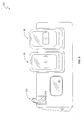
- Figure 4 is a perspective view of a wireless charger configured to charge multiple electronic devices and to calibrate their respective sensors according to one embodiment of the present invention.
- Figure 5 is a flow diagram illustrating a method performed at a battery charger for using the calibration values of one consumer electronic device to set the sensor calibration parameters of one or more other consumer electronic device(s) according to one embodiment of the present invention.
- Figure 6 is a perspective view of a battery charger configured to charge multiple consumer electronic devices and to calibrate their respective sensors according to one embodiment of the present invention.
- Figure 7 is a block diagram illustrating some of the components of a battery charging system configured according to another embodiment of the present invention.
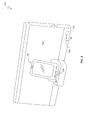
- Figure 8 is a perspective view of a media dock configured to render media files stored on a consumer electronic device, and to calibrate a sensor at the device according to one embodiment of the present invention.
- the present invention provides a sensor calibration function for a base unit for calibrating sensors associated with one or more consumer electronic devices, as well as the sensor algorithms that utilize data output by the sensors, while the devices are communicatively coupled to the base unit (i.e., while the devices are positioned on or electrically connected to the base unit such that the consumer electronic devices and the base unit can communicate data).
- the base unit is configured to perform some intended conventional function, such as charge a battery at the device or render music/video stored at the device.
- the sensor calibration function sends one or more reference values to the consumer electronic device while the device is communicatively coupled to the base unit. Upon receipt, the consumer electronic device uses the reference values to calibrate one or more sensors associated with the device, and/or the sensor algorithms that use the data output by such sensors.
- the ability to set the sensor calibration parameters at the electronic device in this manner helps to ensure that the sensors and the sensor algorithms associated with that device are calibrated.
- many cellular telephones such as Smartphones, have Global Positioning Satellite (GPS) receivers that provide location and navigation services to users.
- GPS Global Positioning Satellite
- Smartphones and/or their accessories e.g., a headset
- a pressure sensor to measure a user's altitude at a given location. Readings from the pressure sensor extend the functionality of a GPS application executing on the device such that a user may be located on, or navigated to/from, a particular floor of a multi-floor building.
- other types of sensors e.g., magnetometers, electronic compasses, accelerometers, gyroscopes, etc. integrated into the Smartphone or other device provides functionality for games and other applications.
- the base unit configured according to the present invention calibrates sensors in different devices in addition to performing its intended conventional function.
- the base unit may comprise a battery charger that charges the batteries of the devices, or a media dock that renders multimedia files stored on the device.
- both the battery charger and the media dock are configured, according to one embodiment of the present invention, to set one or more sensor calibration parameters of one or more sensors at the devices while communicatively coupled to the devices.
- the battery charger and the media dock are configured to set one or more calibration parameters of the sensor algorithms at the devices that use the data from the sensors while communicatively coupled to the devices.
- FIG. 1 is a perspective view of a base unit configured according to one embodiment of the present invention.
- the wireless charging system 10 is configured to charge a battery of a consumer electronic device, such as a cellular telephone 50, as well as set calibration parameters of one or more sensors, and/or the sensor algorithms that use the sensor data, that are associated with one or more such a device.
- system 10 comprises a wireless charger 20 and a receiver unit 40 that is not physically connected to the wireless charger 20 (e.g., using cabling or wires).
- the wireless charger 20 comprises a base having a substantially flat surface referred to herein as a charging platform 22, and connects to an external source of power (not shown) such as an electrical outlet.
- the wireless charger 20 generates a charging voltage from this external power source to charge a battery in the cellular telephone 50.
- the system 10 can utilize any of a variety of well-known technologies to charge the battery.
- the system 10 employs electromagnetic induction to charge the battery of cellular telephone 50.
- electromagnetic induction circuitry in the wireless charger 20 generates a powerful electromagnetic field at a particular frequency from the power provided by the external power source.
- the receiver unit 40 which lies directly on the charging platform 22 and is electrically coupled to the charging circuit in cellular telephone 50, uses the electromagnetic field to generate an electrical current.
- the receiver unit 40 then provides the generated current to the charging circuit in the cellular telephone 50 to charge the battery in cellular telephone 50.
- system 10 can charge the battery of cellular telephone 50.
- these include, but are not limited to, "radio reception” and “resonance.”
- radio reception the wireless charger 20 transmits a wireless signal to the receiver unit 40.
- well-known processing circuitry at the receiver unit 40 Upon receipt of the signal, well-known processing circuitry at the receiver unit 40 generates the charging current from the received wireless signals and transfers the charging current to the cellular telephone 50 to charge the battery.
- “Resonance” combines elements of both the electromagnetic induction and radio reception methods to generate the charging current.
- the wireless charger 20 and the receiver unit 40 each have a coil tuned to the same frequency, with the coil in the charging platform attached to the power source. When the receiver unit 40 is brought near the wireless charger 20, energy is produced because the coils are tuned to the same frequency. This energy is then transferred to the receiver unit 40, which generates the charging current used to charge the battery of cellular telephone 50.
- the wireless charger 20 is not solely used to charge batteries. Rather, the wireless charger 20 is provided with components and functions to allow a user to easily set the calibration parameters of one or more sensors integrated into one or more electronic devices with minimal user interaction.
- the present invention is especially beneficial, as will be seen in more detail later, for setting the calibration parameters of multiple like sensors integrated or associated with other electronic devices.
- FIG. 2 is a block diagram illustrating some of the components in an exemplary system 10 configured according to one embodiment of the present invention.
- the wireless charger 20 comprises a programmable controller 24, a network communications interface 26, a user Input/Output (I/O) interface 28, a memory 30, processing circuitry 32, and a transceiver 34.
- I/O Input/Output
- the controller 24 comprises one or more programmable microprocessors configured to control the user wireless charger 20 according to logic and instructions stored in memory 30.
- control includes the control of conventional functions, such as user I/O, communications, and battery charging functions; however, it also includes the control over non-conventional functions of the wireless charger 20, such as the retrieval, storage, and transmission of a calibration reference value used for setting a sensor calibration parameter for one or more sensors integrated at respective electronic devices, such as the cellular telephone 50, and/or the sensor algorithms that use the data output by such sensors.
- the controller 24 may be configured to retrieve the calibration reference value from any of a variety of different sources.
- the calibration reference value is stored at a network server (not shown).
- the controller 24 communicates with the network server via the communications interface 26 using well-known protocols. Based on information and data provided to the controller 24, as described in more detail below, the controller 24 can retrieve a desired calibration reference value from the network server and transmit the value to the cellular telephone 50 via the receiver unit 40 to set the sensor calibration parameter of the sensor, or a sensor algorithm, at the cellular telephone 50.
- the user can enter the calibration reference value as user input via the user interface 28.
- the user interface 28 may include a display and an input interface (e.g., a keypad or a touch-sensitive display), for example, to allow the user to interact with the wireless charger 20.
- the controller 24 may display one or more prompts to the user to enable the user to enter the calibration reference value.
- the prompts may display helpful information, such as data identifying the cellular telephone 50 and/or a sensor to be calibrated, to assist the user in providing the appropriate values.
- the prompts may display information and data that allows the user (or the wireless charger 20) to retrieve the desired calibration reference values from the network server via the communications interface 26.
- controller 24 may store the values in memory 30, and/or transmit the values to the cellular telephone 50 via the receiver unit 40 to set the sensor calibration parameters.
- Memory 30 is a computer readable medium representing the entire hierarchy of memory in the wireless charger 20.
- Memory 30 may comprise both random access memory (RAM) and read-only memory (ROM), and may be implemented, for example, as one or more discrete devices, stacked devices, or removable devices, such as a flash drive or memory stick, or may be integrated with controller 24.
- Computer program instructions and data required for operating the wireless charger 20 according to the present invention may be stored in non-volatile memory, such as EPROM, EEPROM, and/or flash memory. These include, but are not limited to, the network communications functions and the user I/O interface functions previously described.
- the logic and instructions stored in memory 30 are also capable of controlling the controller 24 to set sensor calibration parameters at the cellular telephone 50 while it is on the charging platform 22. More specifically, a sensor calibration function 36 stored in memory 30, when executed by the controller 24, may control the controller 24 to retrieve the calibration reference values as discussed previously. Thereafter, the sensor calibration function 36 could control the controller 24 to transmit the calibration reference values to set one or more corresponding sensor calibration parameters for the sensor, or the sensor algorithms that use the sensor output, at the cellular telephone 50.
- the processing circuitry 32 includes the components necessary for generating and regulating the charging current used to charge the battery of the cellular telephone 50.
- the transceiver 34 which may be a well-known Near Field Communication (NFC) transceiver, for example, emits the charging current used to charge the cellular telephone 50.
- transceiver 34 also transmits the calibration reference values to the receiver unit 40 for use in setting the sensor calibration parameters at the cellular telephone 50.
- NFC Near Field Communication
- the transmissions need only travel over a distance of a couple of centimeters, but may, in some embodiments, propagate through open space for several meters.
- the receiver unit 40 comprises processing circuitry 42, a transceiver 44 that corresponds to the transceiver 34 of wireless charger 20, and an interface 46 that electrically connects the cellular telephone 50 to the receiver unit 40.
- the processing circuitry 42 processes the received signals using well-known circuitry, and generates the appropriate charging current that is sent to the cellular telephone 50 via interface 46.
- the calibration reference values upon receipt by the transceiver 44, are sent to the cellular telephone 50 via interface 46 for use in setting the sensor calibration parameters.
- the cellular telephone 50 comprises, inter alia, a programmable controller 52, a rechargeable battery 54, an interface 56 that electrically connects the cellular telephone 50 to the receiver unit 40, a memory 58, and one or more sensors 60.
- the sensor 60 may comprise, for example, a pressure sensor configured to detect a current altitude for the cellular telephone 50.
- the cellular telephone 50 may include a GPS receiver and a corresponding application to allow the user of cellular telephone 50 to determine a current location, or to determine a travel route to a destination location. Historically, such applications could only provide a user with information regarding where on the Earth's surface he or she was located. With data provided by pressure sensor 60, however, the application can also determine the altitude of the user.
- the senor 60 and/or the sensor algorithms that utilize the sensor data, must be properly calibrated to accurately determine a user's location in three dimensions.
- certain sensor parameters may be assigned values from time to time.
- the values may be any values needed or desired, the calibration values in one embodiment of the present invention include a reference pressure value and/or a reference height above sea level.
- the cellular telephone 50 may store its calibration values 62 in memory 58.
- Figure 3A is a flow diagram illustrating a method 70 for setting the calibration parameters at cellular telephone 50 according to one embodiment of the present invention.
- the sensor 60 comprises a pressure sensor, and the specific parameter being set is a reference height above sea level.
- the device that houses sensor 60 is illustrated as being cellular telephone 50.
- Sensor 60 may comprise any desired sensor, such as a magnetometer, an accelerometer, and a gyroscope, for example, and be calibrated according to any desired sensor calibration value.
- the device or item that contains sensor 60 need not comprise a cellular telephone.
- the cellular telephone 50 may comprise another different item or device including, but not limited to, a watch, a headset, or tablet computing device, for example.
- Method 70 begins with the wireless charger 20 detecting that a user has placed cellular telephone 50 on the charging platform 22 for charging (box 72). Such detection may be accomplished in any known manner. However, in one embodiment, the user electrically couples the cellular telephone 50 to the receiver unit 40, and then places the receiver unit 40 onto the charging platform 22. Both the wireless charger 20 and the receiver unit 40 have corresponding Near Field Communication (NFC) transceivers 34, 44. As is known in the art, these types of transceivers can detect each other when placed in close proximity to each other.
- NFC Near Field Communication
- NFC Near Field Communication
- wireless charger 20 and the receiver unit 40 operate at a frequency of 13.56 MHz and may transfer data at rates up to 424 Kbs; however, data transfer rates of up to 2 Mbps and above may be possible.
- the distance separating two NFC-capable devices can be anywhere between about 0 and 4 centimeters; however, the distance can be up to about 20 centimeters.
- the transceivers 34, 44 detect each other when the user places the cellular telephone 50 (electrically coupled to the receiver unit 40) in operative charging contact with the wireless charger 20 (i.e., on the charging platform 22).
- the controller 52 sends information identifying the cellular telephone 50 and the sensor 60 to the wireless charger 20 via transceiver 44 in the receiver unit 40 (box 74).
- the exchange of data and information may be accomplished using any known method, however, in one embodiment, the controller 24 at the wireless charger 20 generates and sends a request message to the cellular telephone 50 via receiver unit 40 responsive to the transceiver 44 detecting transceiver 34 (i.e., when the user places the cellular telephone 50 in the receiver unit 40 on the charging platform 22).
- the request message is sent to the controller 52, which then accesses memory 58 to retrieve the requested information and returns the requested information to the controller 24 via the receiver unit 40 in a response message.
- the information may comprise, for example, a Mobile Equipment Identifier (MEI) or a telephone number, and/or an identifier or other unique indicator associated with the sensor integrated in the cellular telephone 50.
- MEI Mobile Equipment Identifier
- the receiver unit 40 then forwards this data and information to the wireless charger 20 via NFC link established between the two transceivers 34, 44.
- the controller 24 at the wireless charger 20 executes a look-up function to retrieve the appropriate reference calibration value for the identified sensor 60 from the memory 30 (box 76). For example, the controller 24 may use the MEI and/or the sensor code as an index into a table of reference values, and select the corresponding reference calibration value for that particular sensor 60. The controller 24 will then set the sensor calibration parameter at the cellular telephone 50 to calibrate the sensor 60 (box 78). For example, while the cellular telephone 50 is on the charging platform 22, the controller 24 may control the transceiver 34 in the wireless charger 20 to transmit the reference calibration value retrieved from the memory 30 to the receiver unit 40. In turn, the receiver unit 40 will send the reference calibration value to the controller 52 in the cellular telephone 50, which will set the sensor calibration parameter using the received value and calibrate the sensor 60.
- the controller 24 executed a look-up function to retrieve a reference calibration value for sensor 62 from memory based on information received from the cellular telephone 50.
- the controller 24 may also generate a query (e.g., a request message) to retrieve the desired reference calibration value(s) from a network server via communication interface 26, or obtain the reference calibration value(s) from the user via user interface 28.
- the wireless charger 20 may also obtain a reference calibration value from an electronic device that is currently on the charging platform 22.
- Figure 3B illustrates such an embodiment.
- the cellular telephone 50 (or other device or item containing the sensor 60) provides a current reference calibration value to the wireless charger 20 for storage in the memory 30.
- Obtaining a current reference value for storage at the wireless device 20 may be beneficial in cases where a sensor may need re-calibration, as may occur from time to time.
- the wireless charger 20 could simply use the saved values to set or re-set the sensor calibration values at the cellular telephone 50, as needed or desired.
- it allows a user to set the calibration parameters of multiple like sensors using a common reference value. This helps to ensure that all electronic devices using the same type of sensor, which may be part of a larger, loosely coupled system, are calibrated similarly.
- method 80 begins when the cellular telephone 50, in the receiver unit 40, is placed on the wireless charging platform 22 (box 82).
- the transceiver 44 at the receiver unit 40 will transmit the identification information associated with the cellular telephone 50 and/or the sensor 60 to the controller 24 at the wireless charger 20 (box 84).
- the receiver unit 40 will also transmit the reference calibration values 62 extracted from memory 58 to the wireless charger 20 (box 86).
- the controller 24 Upon receipt of the information, the controller 24 will update memory 30 to store the received information and reference calibration values (box 88). As previously stated, these functions occur while the cellular telephone 50 is on the charging platform 22.
- Figure 4 is a perspective view illustrating an embodiment wherein a first electronic device (e.g., cellular telephone 50) provides a current calibration value for its sensor 60 to the wireless charger 20 for use as a calibration reference value in setting a sensor calibration parameter of a sensor 92 at a second electronic device 90 (e.g., another cellular telephone), and/or a sensor 102 at a third electronic device 100 (e.g., a wireless headset).
- a first electronic device e.g., cellular telephone 50
- a second electronic device 90 e.g., another cellular telephone
- a sensor 102 at a third electronic device 100 (e.g., a wireless headset).
- the cellular telephone 90 and sensor 92 are similar to the cellular telephone 50 and sensor 60, respectively, seen in previous embodiments.
- a user would electrically couple each cellular telephone 50, 90 to its respective receiver unit 40, and place both devices in operative charging contact with the charger 20 (i.e., on the charging platform 22).
- the wireless headset 100 would have its own receiver unit 104, but is also placed in operative contact with the wireless charger 20.
- wireless charger 20 would then read the current reference calibration value(s) from the memory of one of the devices (e.g., cellular telephone 50) and use that value to set the calibration parameter of the other device(s) 90, 100.
- Such functions are useful for cases where a cellular telephone 50 was recently calibrated at another location, and thus, can now be utilized to calibrate other devices.
- Figure 5 illustrates one embodiment wherein a current sensor calibration value for pressure sensor 60 is read from the cellular telephone 50 and used as a calibration reference value for a pressure sensor 92 in cellular telephone 90.
- a current sensor calibration value for pressure sensor 60 is read from the cellular telephone 50 and used as a calibration reference value for a pressure sensor 92 in cellular telephone 90.
- the description of the method in Figure 5 using two cellular telephones 50, 90 is illustrative only, and that the method may be performed to set the calibration parameters of the sensors in one or more different electronic devices (e.g., headset 100, or a watch, clothing, etc.) as needed or desired.
- Method 110 begins when the user places the cellular telephones 50, 90 in their respective receiver units 40 and onto the platform 22 (box 112). Once on the charging platform 22, the receiver units 40 transmit information and data identifying each device 50, 90 as well as their respective sensors 62, 92, to the wireless charger 20 (box 114). The transmissions may be responsive, for example, to a request message generated and sent by controller 24 in wireless charger 20 as previously described. The receiver unit 40 associated with the cellular telephone 50 then receives a current sensor calibration value from the cellular telephone 50 via the interfaces 46, 56, and transmits that value to the wireless charger 20 (box 116). Upon receipt, the controller 24 at the wireless charger 20 may store the value in memory 30, as previously described.
- controller 24 may also utilize that value to set a sensor calibration parameter of sensor 102.
- the controller 24 may transmit the value received from the cellular telephone 50 to the cellular telephone 90 to set the sensor calibration parameter of the sensor 92 while the cellular telephone 90 is on the charging platform 22 (box 118) and being charged.
- the present invention is not limited to the use of wireless charging platforms, but rather, may also configure other types of battery chargers to send and receive sensor calibration values to and from a variety of different electronic devices.
- Figure 6 illustrates one embodiment in which the charger base comprises a charging station 120 configured to charge the batteries of one or more electronic devices, such as cellular telephones 50, 90, and/or headset 100, as well as to set one or more sensor calibration parameters of the sensors at these devices, as previously described.
- the cellular telephones 50, 90 and the wireless headset 100 are in operative charging contact with the charging station 120 (i.e., each device is electrically coupled to the charging station 120) via a respective charging receptacle or charging bay in the charging station 120.
- each receptacle in charging station 120 includes a male electrical connector or other interface sized to couple to a corresponding female system interface connector on the devices 50, 90, 100.
- one or more of the devices 50, 90, 100 also receive reference calibration values while in operative charging contact with the charging station 120 to use in setting the sensor calibration values of their respective sensors 62, 92, 102.
- a user I/O interface 28 may be included to allow a user to interface with the charging station 120 as previously stated.
- FIG. 7 is a block diagram illustrating some of the components in an exemplary charging station 120 configured according to one embodiment of the present invention.
- the charging station 120 comprises many of the same types of components previously described with respect to the wireless charger 20. These include programmable controller 24, network communications interface 26, user Input/Output (I/O) interface 28, memory 30, and processing circuitry 32. Each of these components are configured to function similarly to those components previously described, and thus, are not described in further detail here.
- the wireless charger 20 included a transceiver 34 to wirelessly communicate sensor reference and calibration values to/from the devices
- charging station 120 includes an interface connector 122 that electrically couples to a corresponding system interface connector 126 disposed on the device being charged (e.g., cellular telephone 50).
- the electrical coupling may comprise a direct connection, or a cable 124 that connects the device to the charging station 120.
- the charging station 120 charges the battery 54 in the cellular telephone 50 (or other device).
- the sensor calibration function 36 associated with charging station 120 controls the charging station 120 to send a reference calibration value to the cellular telephone 50 to set a sensor calibration value of sensor 60, as previously described.
- the present invention may, of course, be carried out in other ways than those specifically set forth herein without departing from essential characteristics of the invention.
- the figures illustrate the sensor calibration parameters as comprising parameters for a sensor.
- the present invention may also send the reference values to a device to calibrate one or more sensor algorithms at the device that use the data output by the sensor.
- the previous embodiments illustrate the consumer electronic devices as being Smartphones or headset accessories.
- the consumer electronic devices may include any type and number of sensors.
- the sensors in such electronic devices may include magnetometers, accelerometers, compasses, or gyroscopes, and be used to facilitate the functions in gaming or medical applications.
- the base unit need not comprise a charging station or charging as described in the previous embodiments. Rather, the base unit may comprise any type of station or dock in which a user of a consumer electronic device having a sensor is apt to place the device from time-to-time. Such a station may or may not include charging circuitry to charge a battery at the consumer electronic device.
- a station is a media dock 130 seen in Figure 8 .
- the media dock includes an interface 132 that connects to the interface 56 on cellular telephone 50. When connected, the cellular telephone 50 is communicatively coupled to the media dock 130 and allows media files, such as music, stored in memory on device 50 to be rendered through a loudspeaker 134.
- the media dock 130 also includes a controller 136, memory 138, and a sensor calibration function 36. While dock 130 is communicatively coupled to the cellular telephone 50, the sensor calibration function 36, which is executed by controller 136, may send a sensor calibration value to the cellular telephone 50 to set a sensor calibration parameter of a sensor at the cellular telephone 50.
- the calibration values sent to cellular telephone 50 may be retrieved from other consumer electronics devices that are coupled to dock 130 from time-to-time, retrieved from memory 138, input by the user via a user interface, or retrieved from a server in a communications network, for example. Therefore, the present embodiments are to be considered in all respects as illustrative and not restrictive, and all changes coming within the meaning and equivalency range of the appended claims are intended to be embraced therein
Landscapes
- Engineering & Computer Science (AREA)
- Remote Sensing (AREA)
- Radar, Positioning & Navigation (AREA)
- Signal Processing (AREA)
- Computer Networks & Wireless Communication (AREA)
- Physics & Mathematics (AREA)
- General Physics & Mathematics (AREA)
- Manufacturing & Machinery (AREA)
- Human Computer Interaction (AREA)
- Telephone Function (AREA)
- Charge And Discharge Circuits For Batteries Or The Like (AREA)
- Power Engineering (AREA)
- Testing Or Calibration Of Command Recording Devices (AREA)
- Arrangements For Transmission Of Measured Signals (AREA)
- Investigating Or Analyzing Materials By The Use Of Electric Means (AREA)
Abstract
Description
- The present invention relates generally to calibrating sensor devices, and more particularly to a system and method for calibrating sensors distributed across one or more consumer electronic devices.
- There are many different types of communication devices currently available. However, one particular type of device presently enjoying an astounding increase in popularity is the Smartphone. One of the reasons for this popularity is that the Smartphone provides functionality that far exceeds that provided by a simple communications device. Particularly, Smartphones generally utilize a touch-sensitive display to allow their users to interact directly with one or more computer applications stored in memory on the device.
- One particularly useful application is a navigation application. Specifically, most Smartphones have an integrated Global Positioning Satellite (GPS) receiver for receiving navigational signals from a plurality of satellites. Based on these signals, the Smartphone can calculate its current position almost anywhere on the Earth's surface and display that position to the user on a touch-sensitive display. Further, given the current location, the application can calculate a route to a destination location for the user.
- Historically, GPS applications were limited by the need to be within the "line-of-sight" of multiple satellites. Therefore, while a GPS application may provide an accurate position fix before the user enters a building, it is difficult for the GPS application to determine the user's position after the user enters the building. The difficulties in providing an accurate indoor position fix can be amplified depending on various factors, such as the construction of the building. Thus, with some GPS applications, it is almost impossible to accurately determine what floor the user is on, as well as whether the user is a particular room or part of the building.
- To address such situations, manufacturers have started integrating a variety of different sensors into their Smartphone devices. One such sensor is a pressure sensor. Generally, pressure sensors are Microelectromechanical System (MEMS) devices that measure changes in atmospheric pressure. With a pressure sensor, a given GPS application may be able to differentiate changes in altitude of less than 1 meter. Thus, a Smartphone equipped with a GPS application and a pressure sensor can be used to determine which floor of a multi-story building that a user is currently occupying.
- Additionally, pressure sensors can be placed into different items or devices that are wearable by people, such as headsets, jewelry, head gear, watches, and so-called "smart" clothing, and used to track their positions within a building. Further, in addition to pressure sensors, other types of sensors, such as a magnetometer, an accelerometer, and/or a gyroscope, may also be integrated within the Smartphone or other device and utilized by the GPS application to estimate a person's location within the building (e.g., within a specific room), or to facilitate the functions of gaming applications, bio or chemo sensor applications, or communications applications, for example.
- Thus, sensors have many different uses and may be integrated into many different types of devices; however, whatever their use or function, the sensors need not be contained within any one single item or device, such as the Smartphone. Instead, the sensors may be distributed across different items and devices. However, to ensure that the sensors and the sensor algorithms that use the sensor data function accurately, the sensors must be calibrated. Sensor calibration can be quite difficult, especially where the sensors are distributed across different items and/or devices.
- The present invention provides a system and method for calibrating sensors that are integrated into electronic devices, such as cellular telephones. In one embodiment, a method of setting a sensor calibration parameter for a sensor in a consumer electronic device comprises communicatively coupling a base unit to a first consumer electronic device having a sensor, and setting a sensor calibration parameter of the sensor while communicatively coupled to the first consumer electronic device.
- In one embodiment, setting a sensor calibration parameter comprises sending a calibration reference value for the sensor calibration parameter to the first consumer electronic device.
- In one embodiment, the base unit comprises a battery charger configured to send the calibration reference value to the first consumer electronic device via an electrical connection electrically the battery charger to the first consumer electronic device.
- In one embodiment, the base unit comprises a wireless charging platform configured to wirelessly transmit the calibration reference value to the first consumer electronic device via a wireless communications link.
- In one embodiment, the base unit comprises a dock configured to send the calibration reference value to the first electronic device via an electrical connection coupling the battery charger to the first consumer electronic device.
- In one embodiment, the method further comprises receiving the calibration reference value as user input.
- In one embodiment, the method further comprises receiving data transmitted by the first consumer electronic device while the first consumer electronic device is communicatively coupled to the base unit, and obtaining the calibration reference value based on the received data.
- In one embodiment, obtaining the calibration reference value based on the received data comprises retrieving the calibration reference value from a memory at the base unit.
- In one embodiment, obtaining the calibration reference value comprises retrieving the calibration reference value from a network server via a communications interface at the base unit.
- In one embodiment, the method further comprises communicatively coupling the sensor calibration function to a second consumer electronic device having a sensor, reading a calibration reference value from the second consumer electronic device, and setting the sensor calibration parameter of the sensor in the first consumer electronic device based on the calibration reference value read from the second consumer electronic device while communicatively coupled to the second consumer electronic device.
- In one embodiment, setting a sensor calibration parameter comprises sending a calibration reference value to set the sensor calibration parameter of a sensor algorithm that operates on data output by the sensor to the first consumer electronic device.
- The present invention also provides an apparatus configured to perform the method of the invention. In one embodiment, the apparatus comprises a base unit having a sensor calibration function. The base unit comprises a base configured to communicatively couple to a first consumer electronic device having a sensor, and a controller configured to set a sensor calibration parameter of the sensor while communicatively coupled to the first consumer electronic device.
- In one embodiment, the controller is configured to set the sensor calibration parameter by sending a calibration reference value to the first consumer electronic device.
- In one embodiment, the base unit comprises a battery charger configured to send the calibration reference value to the first consumer electronic device via an electrical connection electrically connecting the battery charger to the first consumer electronic device.
- In one embodiment, the base unit comprises a wireless charging platform having a wireless transceiver, and wherein the controller is further configured to transmit the calibration reference value to the first consumer electronic device via the transceiver.
- In one embodiment, the base unit comprises a dock, and wherein the controller is further configured to send the calibration reference value to the first consumer electronic device via an electrical connection connecting the dock to the first consumer electronic device.
- In one embodiment, the base unit further comprises a user interface configured to receive the calibration reference value as user input.
- In one embodiment, the controller is further configured to receive data transmitted by the first consumer electronic device, and obtain the calibration reference value based on the received data.
- In one embodiment, the base unit further comprises a communications interface connecting the base unit to a network server, and wherein the controller is further configured to retrieve the calibration reference value from the network server.
- In one embodiment, the base unit is further configured to communicatively couple to a second consumer electronic device having a sensor. In such embodiments, the controller is further configured to read a calibration reference value from the second consumer electronic device, and set the sensor calibration parameter at the first consumer electronic device based on the calibration reference value.
- Of course, those skilled in the art will appreciate that the present invention is not limited to the above contexts or examples, and will recognize additional features and advantages upon reading the following detailed description and upon viewing the accompanying drawings.
-
Figure 1 is a perspective view of a base unit configured as a wireless charger that charges the batteries of a consumer electronic device and calibrates its sensors according to one embodiment of the present invention. -
Figure 2 is a block diagram illustrating some of the components of a wireless charging system configured according to one embodiment of the present invention. -
Figure 3A is a flow diagram illustrating a method performed at a battery charger for providing reference values to set the calibration parameters of one or more sensors at a consumer electronic device according to one embodiment of the present invention. -
Figure 3B is a flow diagram illustrating a method performed at a battery charger for receiving one or more calibration values from a consumer electronic device being charged for storage in memory according to one embodiment of the present invention. -
Figure 4 is a perspective view of a wireless charger configured to charge multiple electronic devices and to calibrate their respective sensors according to one embodiment of the present invention. -
Figure 5 is a flow diagram illustrating a method performed at a battery charger for using the calibration values of one consumer electronic device to set the sensor calibration parameters of one or more other consumer electronic device(s) according to one embodiment of the present invention. -
Figure 6 is a perspective view of a battery charger configured to charge multiple consumer electronic devices and to calibrate their respective sensors according to one embodiment of the present invention. -
Figure 7 is a block diagram illustrating some of the components of a battery charging system configured according to another embodiment of the present invention. -
Figure 8 is a perspective view of a media dock configured to render media files stored on a consumer electronic device, and to calibrate a sensor at the device according to one embodiment of the present invention. - The present invention provides a sensor calibration function for a base unit for calibrating sensors associated with one or more consumer electronic devices, as well as the sensor algorithms that utilize data output by the sensors, while the devices are communicatively coupled to the base unit (i.e., while the devices are positioned on or electrically connected to the base unit such that the consumer electronic devices and the base unit can communicate data). More particularly, the base unit is configured to perform some intended conventional function, such as charge a battery at the device or render music/video stored at the device. In addition, however, the sensor calibration function sends one or more reference values to the consumer electronic device while the device is communicatively coupled to the base unit. Upon receipt, the consumer electronic device uses the reference values to calibrate one or more sensors associated with the device, and/or the sensor algorithms that use the data output by such sensors.
- The ability to set the sensor calibration parameters at the electronic device in this manner helps to ensure that the sensors and the sensor algorithms associated with that device are calibrated. For example, many cellular telephones, such as Smartphones, have Global Positioning Satellite (GPS) receivers that provide location and navigation services to users. Additionally, many Smartphones and/or their accessories (e.g., a headset) also have a pressure sensor to measure a user's altitude at a given location. Readings from the pressure sensor extend the functionality of a GPS application executing on the device such that a user may be located on, or navigated to/from, a particular floor of a multi-floor building. Similarly, other types of sensors (e.g., magnetometers, electronic compasses, accelerometers, gyroscopes, etc.) integrated into the Smartphone or other device provides functionality for games and other applications.
- To operate properly, a sensor and/or an algorithm that utilizes the data output by the sensor should be accurately calibrated. However, such calibration can be difficult. This is especially true when one must calibrate multiple sensors, or their associated algorithms, integrated into a plurality of different devices. Therefore, the base unit configured according to the present invention calibrates sensors in different devices in addition to performing its intended conventional function. By way of example only, the base unit may comprise a battery charger that charges the batteries of the devices, or a media dock that renders multimedia files stored on the device. In either case, both the battery charger and the media dock are configured, according to one embodiment of the present invention, to set one or more sensor calibration parameters of one or more sensors at the devices while communicatively coupled to the devices. In another embodiment, the battery charger and the media dock are configured to set one or more calibration parameters of the sensor algorithms at the devices that use the data from the sensors while communicatively coupled to the devices.
- Turning now to the drawings,
Figure 1 is a perspective view of a base unit configured according to one embodiment of the present invention. As seen inFigure 1 , thewireless charging system 10 is configured to charge a battery of a consumer electronic device, such as acellular telephone 50, as well as set calibration parameters of one or more sensors, and/or the sensor algorithms that use the sensor data, that are associated with one or more such a device. To that end,system 10 comprises awireless charger 20 and areceiver unit 40 that is not physically connected to the wireless charger 20 (e.g., using cabling or wires). Thewireless charger 20 comprises a base having a substantially flat surface referred to herein as a chargingplatform 22, and connects to an external source of power (not shown) such as an electrical outlet. As is known in the art, thewireless charger 20 generates a charging voltage from this external power source to charge a battery in thecellular telephone 50. - The
system 10 can utilize any of a variety of well-known technologies to charge the battery. For example, in one embodiment of the present invention, thesystem 10 employs electromagnetic induction to charge the battery ofcellular telephone 50. With electromagnetic induction, circuitry in thewireless charger 20 generates a powerful electromagnetic field at a particular frequency from the power provided by the external power source. Thereceiver unit 40, which lies directly on the chargingplatform 22 and is electrically coupled to the charging circuit incellular telephone 50, uses the electromagnetic field to generate an electrical current. Thereceiver unit 40 then provides the generated current to the charging circuit in thecellular telephone 50 to charge the battery incellular telephone 50. - There are, of course, other equally suitable and well-known technologies by which
system 10 can charge the battery ofcellular telephone 50. These include, but are not limited to, "radio reception" and "resonance." With "radio reception," thewireless charger 20 transmits a wireless signal to thereceiver unit 40. Upon receipt of the signal, well-known processing circuitry at thereceiver unit 40 generates the charging current from the received wireless signals and transfers the charging current to thecellular telephone 50 to charge the battery. "Resonance" combines elements of both the electromagnetic induction and radio reception methods to generate the charging current. Specifically, thewireless charger 20 and thereceiver unit 40 each have a coil tuned to the same frequency, with the coil in the charging platform attached to the power source. When thereceiver unit 40 is brought near thewireless charger 20, energy is produced because the coils are tuned to the same frequency. This energy is then transferred to thereceiver unit 40, which generates the charging current used to charge the battery ofcellular telephone 50. - According to the present invention, the
wireless charger 20 is not solely used to charge batteries. Rather, thewireless charger 20 is provided with components and functions to allow a user to easily set the calibration parameters of one or more sensors integrated into one or more electronic devices with minimal user interaction. The present invention is especially beneficial, as will be seen in more detail later, for setting the calibration parameters of multiple like sensors integrated or associated with other electronic devices. -
Figure 2 is a block diagram illustrating some of the components in anexemplary system 10 configured according to one embodiment of the present invention. As seen inFigure 2 , thewireless charger 20 comprises aprogrammable controller 24, anetwork communications interface 26, a user Input/Output (I/O)interface 28, amemory 30, processingcircuitry 32, and atransceiver 34. - The
controller 24 comprises one or more programmable microprocessors configured to control theuser wireless charger 20 according to logic and instructions stored inmemory 30. Such control includes the control of conventional functions, such as user I/O, communications, and battery charging functions; however, it also includes the control over non-conventional functions of thewireless charger 20, such as the retrieval, storage, and transmission of a calibration reference value used for setting a sensor calibration parameter for one or more sensors integrated at respective electronic devices, such as thecellular telephone 50, and/or the sensor algorithms that use the data output by such sensors. - The
controller 24 may be configured to retrieve the calibration reference value from any of a variety of different sources. In one embodiment, for example, the calibration reference value is stored at a network server (not shown). In such embodiments, thecontroller 24 communicates with the network server via thecommunications interface 26 using well-known protocols. Based on information and data provided to thecontroller 24, as described in more detail below, thecontroller 24 can retrieve a desired calibration reference value from the network server and transmit the value to thecellular telephone 50 via thereceiver unit 40 to set the sensor calibration parameter of the sensor, or a sensor algorithm, at thecellular telephone 50. - In another embodiment, the user can enter the calibration reference value as user input via the
user interface 28. In these embodiments, theuser interface 28 may include a display and an input interface (e.g., a keypad or a touch-sensitive display), for example, to allow the user to interact with thewireless charger 20. In these embodiments, thecontroller 24 may display one or more prompts to the user to enable the user to enter the calibration reference value. For example, the prompts may display helpful information, such as data identifying thecellular telephone 50 and/or a sensor to be calibrated, to assist the user in providing the appropriate values. Alternatively, or in addition, the prompts may display information and data that allows the user (or the wireless charger 20) to retrieve the desired calibration reference values from the network server via thecommunications interface 26. However thewireless charger 20 obtains the values,controller 24 may store the values inmemory 30, and/or transmit the values to thecellular telephone 50 via thereceiver unit 40 to set the sensor calibration parameters. -
Memory 30 is a computer readable medium representing the entire hierarchy of memory in thewireless charger 20.Memory 30 may comprise both random access memory (RAM) and read-only memory (ROM), and may be implemented, for example, as one or more discrete devices, stacked devices, or removable devices, such as a flash drive or memory stick, or may be integrated withcontroller 24. Computer program instructions and data required for operating thewireless charger 20 according to the present invention may be stored in non-volatile memory, such as EPROM, EEPROM, and/or flash memory. These include, but are not limited to, the network communications functions and the user I/O interface functions previously described. - The logic and instructions stored in
memory 30 are also capable of controlling thecontroller 24 to set sensor calibration parameters at thecellular telephone 50 while it is on the chargingplatform 22. More specifically, asensor calibration function 36 stored inmemory 30, when executed by thecontroller 24, may control thecontroller 24 to retrieve the calibration reference values as discussed previously. Thereafter, thesensor calibration function 36 could control thecontroller 24 to transmit the calibration reference values to set one or more corresponding sensor calibration parameters for the sensor, or the sensor algorithms that use the sensor output, at thecellular telephone 50. - The
processing circuitry 32 includes the components necessary for generating and regulating the charging current used to charge the battery of thecellular telephone 50. Thetransceiver 34, which may be a well-known Near Field Communication (NFC) transceiver, for example, emits the charging current used to charge thecellular telephone 50. In addition,transceiver 34 also transmits the calibration reference values to thereceiver unit 40 for use in setting the sensor calibration parameters at thecellular telephone 50. Generally, the transmissions need only travel over a distance of a couple of centimeters, but may, in some embodiments, propagate through open space for several meters. - The
receiver unit 40 comprises processingcircuitry 42, atransceiver 44 that corresponds to thetransceiver 34 ofwireless charger 20, and aninterface 46 that electrically connects thecellular telephone 50 to thereceiver unit 40. The signals transmitted by thetransceiver 34 atwireless charger 20, regardless of whether those signals are used as a charging current, or for setting the calibration parameters of the sensor, are received by thetransceiver 44. Theprocessing circuitry 42 processes the received signals using well-known circuitry, and generates the appropriate charging current that is sent to thecellular telephone 50 viainterface 46. The calibration reference values, upon receipt by thetransceiver 44, are sent to thecellular telephone 50 viainterface 46 for use in setting the sensor calibration parameters. - The
cellular telephone 50 comprises, inter alia, aprogrammable controller 52, arechargeable battery 54, aninterface 56 that electrically connects thecellular telephone 50 to thereceiver unit 40, amemory 58, and one ormore sensors 60. Thesensor 60 may comprise, for example, a pressure sensor configured to detect a current altitude for thecellular telephone 50. Specifically, thecellular telephone 50 may include a GPS receiver and a corresponding application to allow the user ofcellular telephone 50 to determine a current location, or to determine a travel route to a destination location. Historically, such applications could only provide a user with information regarding where on the Earth's surface he or she was located. With data provided bypressure sensor 60, however, the application can also determine the altitude of the user. - However, as previously stated, the
sensor 60, and/or the sensor algorithms that utilize the sensor data, must be properly calibrated to accurately determine a user's location in three dimensions. Thus, certain sensor parameters may be assigned values from time to time. Although the values may be any values needed or desired, the calibration values in one embodiment of the present invention include a reference pressure value and/or a reference height above sea level. As seen inFigure 2 , thecellular telephone 50 may store itscalibration values 62 inmemory 58. -
Figure 3A is a flow diagram illustrating amethod 70 for setting the calibration parameters atcellular telephone 50 according to one embodiment of the present invention. In this embodiment, thesensor 60 comprises a pressure sensor, and the specific parameter being set is a reference height above sea level. Further, the device that housessensor 60 is illustrated as beingcellular telephone 50. However, as stated previously, those skilled in the art will readily appreciate that this is for illustrative purposes only.Sensor 60 may comprise any desired sensor, such as a magnetometer, an accelerometer, and a gyroscope, for example, and be calibrated according to any desired sensor calibration value. Additionally, the device or item that containssensor 60 need not comprise a cellular telephone. As seen in more detail later, thecellular telephone 50 may comprise another different item or device including, but not limited to, a watch, a headset, or tablet computing device, for example. -
Method 70 begins with thewireless charger 20 detecting that a user has placedcellular telephone 50 on the chargingplatform 22 for charging (box 72). Such detection may be accomplished in any known manner. However, in one embodiment, the user electrically couples thecellular telephone 50 to thereceiver unit 40, and then places thereceiver unit 40 onto the chargingplatform 22. Both thewireless charger 20 and thereceiver unit 40 have corresponding Near Field Communication (NFC)transceivers - More particularly, Near Field Communication is a well-known short-range wireless connectivity technology that uses magnetic field induction to permit devices to share information with each other. Typically, NFC devices operate at a frequency of 13.56 MHz and may transfer data at rates up to 424 Kbs; however, data transfer rates of up to 2 Mbps and above may be possible. Communication between two NFC-capable devices, such as the
wireless charger 20 and thereceiver unit 40, occurs when they are brought into contact with each other, or within close physical proximity of one another. Typically, the distance separating two NFC-capable devices can be anywhere between about 0 and 4 centimeters; however, the distance can be up to about 20 centimeters. - In the present embodiment, the
transceivers platform 22, thecontroller 52 sends information identifying thecellular telephone 50 and thesensor 60 to thewireless charger 20 viatransceiver 44 in the receiver unit 40 (box 74). The exchange of data and information may be accomplished using any known method, however, in one embodiment, thecontroller 24 at thewireless charger 20 generates and sends a request message to thecellular telephone 50 viareceiver unit 40 responsive to thetransceiver 44 detecting transceiver 34 (i.e., when the user places thecellular telephone 50 in thereceiver unit 40 on the charging platform 22). The request message is sent to thecontroller 52, which then accessesmemory 58 to retrieve the requested information and returns the requested information to thecontroller 24 via thereceiver unit 40 in a response message. The information may comprise, for example, a Mobile Equipment Identifier (MEI) or a telephone number, and/or an identifier or other unique indicator associated with the sensor integrated in thecellular telephone 50. Thereceiver unit 40 then forwards this data and information to thewireless charger 20 via NFC link established between the twotransceivers - Upon receipt of the identifying information, the
controller 24 at thewireless charger 20 executes a look-up function to retrieve the appropriate reference calibration value for the identifiedsensor 60 from the memory 30 (box 76). For example, thecontroller 24 may use the MEI and/or the sensor code as an index into a table of reference values, and select the corresponding reference calibration value for thatparticular sensor 60. Thecontroller 24 will then set the sensor calibration parameter at thecellular telephone 50 to calibrate the sensor 60 (box 78). For example, while thecellular telephone 50 is on the chargingplatform 22, thecontroller 24 may control thetransceiver 34 in thewireless charger 20 to transmit the reference calibration value retrieved from thememory 30 to thereceiver unit 40. In turn, thereceiver unit 40 will send the reference calibration value to thecontroller 52 in thecellular telephone 50, which will set the sensor calibration parameter using the received value and calibrate thesensor 60. - In the embodiment of
Figure 3A , thecontroller 24 executed a look-up function to retrieve a reference calibration value forsensor 62 from memory based on information received from thecellular telephone 50. However, the present invention is not so limited. As previously described, thecontroller 24 may also generate a query (e.g., a request message) to retrieve the desired reference calibration value(s) from a network server viacommunication interface 26, or obtain the reference calibration value(s) from the user viauser interface 28. - In addition, the
wireless charger 20 may also obtain a reference calibration value from an electronic device that is currently on the chargingplatform 22.Figure 3B illustrates such an embodiment. Particularly, the cellular telephone 50 (or other device or item containing the sensor 60) provides a current reference calibration value to thewireless charger 20 for storage in thememory 30. Obtaining a current reference value for storage at thewireless device 20 may be beneficial in cases where a sensor may need re-calibration, as may occur from time to time. Specifically, with the values inmemory 30, thewireless charger 20 could simply use the saved values to set or re-set the sensor calibration values at thecellular telephone 50, as needed or desired. Also, as seen in more detail below, it allows a user to set the calibration parameters of multiple like sensors using a common reference value. This helps to ensure that all electronic devices using the same type of sensor, which may be part of a larger, loosely coupled system, are calibrated similarly. - As seen in
Figure 3B ,method 80 begins when thecellular telephone 50, in thereceiver unit 40, is placed on the wireless charging platform 22 (box 82). In response, thetransceiver 44 at thereceiver unit 40 will transmit the identification information associated with thecellular telephone 50 and/or thesensor 60 to thecontroller 24 at the wireless charger 20 (box 84). Thereceiver unit 40 will also transmit the reference calibration values 62 extracted frommemory 58 to the wireless charger 20 (box 86). Upon receipt of the information, thecontroller 24 will updatememory 30 to store the received information and reference calibration values (box 88). As previously stated, these functions occur while thecellular telephone 50 is on the chargingplatform 22. -
Figure 4 is a perspective view illustrating an embodiment wherein a first electronic device (e.g., cellular telephone 50) provides a current calibration value for itssensor 60 to thewireless charger 20 for use as a calibration reference value in setting a sensor calibration parameter of asensor 92 at a second electronic device 90 (e.g., another cellular telephone), and/or asensor 102 at a third electronic device 100 (e.g., a wireless headset). As seen inFigure 4 , thecellular telephone 90 andsensor 92 are similar to thecellular telephone 50 andsensor 60, respectively, seen in previous embodiments. Thus, a user would electrically couple eachcellular telephone respective receiver unit 40, and place both devices in operative charging contact with the charger 20 (i.e., on the charging platform 22). Thewireless headset 100 would have itsown receiver unit 104, but is also placed in operative contact with thewireless charger 20. Once thedevices platform 22,wireless charger 20 would then read the current reference calibration value(s) from the memory of one of the devices (e.g., cellular telephone 50) and use that value to set the calibration parameter of the other device(s) 90, 100. Such functions are useful for cases where acellular telephone 50 was recently calibrated at another location, and thus, can now be utilized to calibrate other devices. -
Figure 5 illustrates one embodiment wherein a current sensor calibration value forpressure sensor 60 is read from thecellular telephone 50 and used as a calibration reference value for apressure sensor 92 incellular telephone 90. Those skilled in the art will appreciate that the description of the method inFigure 5 using twocellular telephones headset 100, or a watch, clothing, etc.) as needed or desired. -
Method 110 begins when the user places thecellular telephones respective receiver units 40 and onto the platform 22 (box 112). Once on the chargingplatform 22, thereceiver units 40 transmit information and data identifying eachdevice respective sensors controller 24 inwireless charger 20 as previously described. Thereceiver unit 40 associated with thecellular telephone 50 then receives a current sensor calibration value from thecellular telephone 50 via theinterfaces controller 24 at thewireless charger 20 may store the value inmemory 30, as previously described. However, according to one embodiment,controller 24 may also utilize that value to set a sensor calibration parameter ofsensor 102. Particularly, thecontroller 24 may transmit the value received from thecellular telephone 50 to thecellular telephone 90 to set the sensor calibration parameter of thesensor 92 while thecellular telephone 90 is on the charging platform 22 (box 118) and being charged. - As stated above, the present invention is not limited to the use of wireless charging platforms, but rather, may also configure other types of battery chargers to send and receive sensor calibration values to and from a variety of different electronic devices.
Figure 6 illustrates one embodiment in which the charger base comprises a chargingstation 120 configured to charge the batteries of one or more electronic devices, such ascellular telephones headset 100, as well as to set one or more sensor calibration parameters of the sensors at these devices, as previously described. - As seen in
Figure 6 , thecellular telephones wireless headset 100 are in operative charging contact with the charging station 120 (i.e., each device is electrically coupled to the charging station 120) via a respective charging receptacle or charging bay in the chargingstation 120. Particularly, each receptacle in chargingstation 120 includes a male electrical connector or other interface sized to couple to a corresponding female system interface connector on thedevices devices devices station 120 to use in setting the sensor calibration values of theirrespective sensors O interface 28 may be included to allow a user to interface with the chargingstation 120 as previously stated. -
Figure 7 is a block diagram illustrating some of the components in anexemplary charging station 120 configured according to one embodiment of the present invention. As seen inFigure 7 , the chargingstation 120 comprises many of the same types of components previously described with respect to thewireless charger 20. These includeprogrammable controller 24,network communications interface 26, user Input/Output (I/O)interface 28,memory 30, andprocessing circuitry 32. Each of these components are configured to function similarly to those components previously described, and thus, are not described in further detail here. However, where thewireless charger 20 included atransceiver 34 to wirelessly communicate sensor reference and calibration values to/from the devices, chargingstation 120 includes aninterface connector 122 that electrically couples to a correspondingsystem interface connector 126 disposed on the device being charged (e.g., cellular telephone 50). The electrical coupling may comprise a direct connection, or acable 124 that connects the device to the chargingstation 120. In operation, the chargingstation 120 charges thebattery 54 in the cellular telephone 50 (or other device). Additionally, while thecellular telephone 50 is in operative charging contact with the chargingstation 120, thesensor calibration function 36 associated with chargingstation 120 controls the chargingstation 120 to send a reference calibration value to thecellular telephone 50 to set a sensor calibration value ofsensor 60, as previously described. - The present invention may, of course, be carried out in other ways than those specifically set forth herein without departing from essential characteristics of the invention. For example, the figures illustrate the sensor calibration parameters as comprising parameters for a sensor. However, this is for illustrative purposes only. As previously stated, the present invention may also send the reference values to a device to calibrate one or more sensor algorithms at the device that use the data output by the sensor.
- Additionally, the previous embodiments illustrate the consumer electronic devices as being Smartphones or headset accessories. However, those skilled in the art will appreciate that other devices having sensors, such as watches, glasses, and smart clothing, are also suitable. Further, the consumer electronic devices may include any type and number of sensors. For example, in other embodiments, the sensors in such electronic devices may include magnetometers, accelerometers, compasses, or gyroscopes, and be used to facilitate the functions in gaming or medical applications.
- Additionally, the base unit need not comprise a charging station or charging as described in the previous embodiments. Rather, the base unit may comprise any type of station or dock in which a user of a consumer electronic device having a sensor is apt to place the device from time-to-time. Such a station may or may not include charging circuitry to charge a battery at the consumer electronic device. One example of such a station is a
media dock 130 seen inFigure 8 . The media dock includes aninterface 132 that connects to theinterface 56 oncellular telephone 50. When connected, thecellular telephone 50 is communicatively coupled to themedia dock 130 and allows media files, such as music, stored in memory ondevice 50 to be rendered through aloudspeaker 134. - Like the previous embodiments, the
media dock 130 also includes acontroller 136,memory 138, and asensor calibration function 36. Whiledock 130 is communicatively coupled to thecellular telephone 50, thesensor calibration function 36, which is executed bycontroller 136, may send a sensor calibration value to thecellular telephone 50 to set a sensor calibration parameter of a sensor at thecellular telephone 50. The calibration values sent tocellular telephone 50 may be retrieved from other consumer electronics devices that are coupled to dock 130 from time-to-time, retrieved frommemory 138, input by the user via a user interface, or retrieved from a server in a communications network, for example. Therefore, the present embodiments are to be considered in all respects as illustrative and not restrictive, and all changes coming within the meaning and equivalency range of the appended claims are intended to be embraced therein
Claims (15)
- A method of setting a sensor calibration parameter for a sensor (60) in a consumer electronic device, the method comprising:communicatively coupling a base unit (10) to a first consumer electronic device (50) having a sensor (60); andsetting a sensor calibration parameter of the sensor (60) while communicatively coupled to the first consumer electronic device (50).
- The method of claim 1 wherein setting a sensor calibration parameter comprises sending a calibration reference value (62) for the sensor calibration parameter to the first consumer electronic device (50), and wherein the base unit (10) comprises a battery charger (20) configured to send the calibration reference value (62) to the first consumer electronic device (50) via an electrical connection electrically connecting the battery charger to the first consumer electronic device (50).
- The method of claim 1 or claim 2 wherein setting a sensor calibration parameter comprises sending a calibration reference value (62) for the sensor calibration parameter to the first consumer electronic device (50), and wherein the base unit (40) comprises a wireless charging platform (22) configured to wirelessly transmit the calibration reference value (62) to the first consumer electronic device (50) via a wireless communications link.
- The method of any one of claims 1-3 wherein setting a sensor calibration parameter comprises sending a calibration reference value (62) for the sensor calibration parameter to the first consumer electronic device (50), and wherein the base unit (40) comprises a dock (130) configured to send the calibration reference value (62) to the first electronic device (50) via an electrical connection coupling the battery charger (20) to the first consumer electronic device (50).
- The method of any one of claims 1-4 wherein setting a sensor calibration parameter comprises sending a calibration reference value (62) for the sensor calibration parameter to the first consumer electronic device (50), and further comprising receiving the calibration reference value (62) as user input.
- The method of any one of claims 1-5 wherein setting a sensor calibration parameter comprises sending a calibration reference value (62) for the sensor calibration parameter to the first consumer electronic device (50), and further comprising:receiving data transmitted by the first consumer electronic device (50) while the first consumer electronic device (50) is communicatively coupled to the base unit (10); andobtaining the calibration reference value (62) based on the received data.
- The method of any one of claims 1-6 further comprising:communicatively coupling the sensor calibration function (36) to a second consumer electronic device (90) having a sensor (92);reading a calibration reference value (62) from the second consumer electronic device (90); andsetting the sensor calibration parameter of the sensor (60) in the first consumer electronic device (50) based on the calibration reference value (62) read from the second consumer electronic device (90) while communicatively coupled to the second consumer electronic device (90).
- The method of any one of claims 1-7 wherein setting a sensor calibration parameter comprises sending a calibration reference value (62) to set the sensor calibration parameter of a sensor algorithm that operates on data output by the sensor (60) to the first consumer electronic device (50).
- A base unit (10) having a sensor calibration function (36), the base unit (40) comprising:a base configured to communicatively couple to a first consumer electronic device (50) having a sensor (60); anda controller (24; 52) configured to set a sensor calibration parameter of the sensor (60) while communicatively coupled to the first consumer electronic device (50).
- The base unit (10) of claim 9 wherein the controller (24; 52) is configured to set the sensor calibration parameter by sending a calibration reference value (62) to the first consumer electronic device (50), and wherein the base unit comprises a battery charger (20) configured to send the calibration reference value (62) to the first consumer electronic device (50) via an electrical connection electrically connecting the battery charger to the first consumer electronic device (50).
- The base unit (10) of claim 9 or claim 10 wherein the controller (24; 52) is configured to set the sensor calibration parameter by sending a calibration reference value (62) to the first consumer electronic device (50), and wherein the base unit comprises a wireless charging platform (22) having a wireless transceiver (34; 44), and wherein the controller (24; 52) is further configured to transmit the calibration reference value (62) to the first consumer electronic device (50) via the transceiver (34; 44).
- The base unit (10) of any one of claims 9-11 wherein the controller (24; 52) is configured to set the sensor calibration parameter by sending a calibration reference value (62) to the first consumer electronic device (50), and wherein the base unit (40) comprises a dock (130), and wherein the controller (24; 52) is further configured to send the calibration reference value (62) to the first consumer electronic device (50) via an electrical connection connecting the dock (130) to the first consumer electronic device (50).
- The base unit (10) of any one of claims 9-12 wherein the controller (24; 52) is configured to set the sensor calibration parameter by sending a calibration reference value (62) to the first consumer electronic device (50), and further comprising a user interface (28) configured to receive the calibration reference value (62) as user input.
- The base unit (10) of any one of claims 9-13 wherein the controller (24; 52) is configured to set the sensor calibration parameter by sending a calibration reference value (62) to the first consumer electronic device (50), and wherein the controller (24; 52) is further configured to:receive data transmitted by the first consumer electronic device (50); andobtain the calibration reference value (62) based on the received data.
- The base unit (10) of any one of claims 9-14 wherein the base unit (10) is further configured to communicatively couple to a second consumer electronic device (90) having a sensor (92), and wherein the controller (24; 52) is further configured to:read a calibration reference value (62) from the second consumer electronic device (90); andset the sensor calibration parameter at the first consumer electronic device (50) based on the calibration reference value (62).
Applications Claiming Priority (2)
| Application Number | Priority Date | Filing Date | Title |
|---|---|---|---|
| US201161555269P | 2011-11-03 | 2011-11-03 | |
| US13/549,293 US10948289B2 (en) | 2011-11-03 | 2012-07-13 | System and method for calibrating sensors across loosely coupled consumer electronic devices |
Publications (3)
| Publication Number | Publication Date |
|---|---|
| EP2589927A2 true EP2589927A2 (en) | 2013-05-08 |
| EP2589927A3 EP2589927A3 (en) | 2016-09-21 |
| EP2589927B1 EP2589927B1 (en) | 2019-05-22 |
Family
ID=47594171
Family Applications (1)
| Application Number | Title | Priority Date | Filing Date |
|---|---|---|---|
| EP12007217.8A Not-in-force EP2589927B1 (en) | 2011-11-03 | 2012-10-18 | System and method for calibrating sensors in consumer electronic devices by coupling to a base unit |
Country Status (2)
| Country | Link |
|---|---|
| US (1) | US10948289B2 (en) |
| EP (1) | EP2589927B1 (en) |
Cited By (3)
| Publication number | Priority date | Publication date | Assignee | Title |
|---|---|---|---|---|
| CN105115522A (en) * | 2015-09-16 | 2015-12-02 | 清华大学 | Electrostatic gyro servo testing device based on turntable position working mode |
| WO2017039914A1 (en) * | 2015-09-02 | 2017-03-09 | Qualcomm Incorporated | Auto-calibrating light sensor data of a mobile device |
| GB2553349A (en) * | 2016-09-04 | 2018-03-07 | Draeger Safety Uk Ltd | Method and system for calibrating one or more sensors of an inertial measurement unit and/or initialising an intertial measurement unit |
Families Citing this family (11)
| Publication number | Priority date | Publication date | Assignee | Title |
|---|---|---|---|---|
| EP2667280A1 (en) * | 2012-05-23 | 2013-11-27 | Nxp B.V. | Device Control System And Method Of Determining Altitude |
| US10030993B2 (en) * | 2012-11-01 | 2018-07-24 | Verizon Connect Inc. | Method and system for determining whether steps have occurred |
| US10146723B2 (en) * | 2013-11-21 | 2018-12-04 | Sigsense Technologies, Inc. | Sensor data correlation and analysis platform |
| US11054289B2 (en) * | 2014-06-11 | 2021-07-06 | At&T Intellectual Property I, L.P. | Sensor calibration |
| WO2016025895A1 (en) * | 2014-08-15 | 2016-02-18 | Qualcomm Incorporated | Mobile-assisted determination of the altitude of a mobile device |
| US9746933B2 (en) * | 2015-05-20 | 2017-08-29 | Survios, Inc. | Systems and methods for natural motion interaction with a virtual environment |
| US11911211B2 (en) | 2015-06-15 | 2024-02-27 | Cvr Medical Corporation | Yoke for sensing carotid stenosis |
| EP3620752A1 (en) | 2018-09-05 | 2020-03-11 | Sword Health, S.A. | Method and system for calibrating sensors |
| US11851205B2 (en) | 2020-07-06 | 2023-12-26 | Honeywell International Inc. | Air quality monitoring |
| US11635312B2 (en) * | 2020-07-06 | 2023-04-25 | Honeywell International Inc. | Systems and methods for remote sensor calibration |
| CN112781641A (en) * | 2020-12-01 | 2021-05-11 | 西安中星测控有限公司 | Wireless calibration device and method for sensor |
Family Cites Families (18)
| Publication number | Priority date | Publication date | Assignee | Title |
|---|---|---|---|---|
| US6473483B2 (en) | 1998-10-28 | 2002-10-29 | Nathan Pyles | Pedometer |
| US6518918B1 (en) | 2000-05-11 | 2003-02-11 | Lucent Technologies Inc. | Wireless assisted altitude measurement |
| US7197541B1 (en) * | 2001-06-18 | 2007-03-27 | Palm, Inc. | Method and apparatus for automated personality transfer for a wireless enabled handheld device |
| US7376846B2 (en) * | 2001-10-14 | 2008-05-20 | Palm, Inc. | Charging and communication cable system for a mobile computer apparatus |
| ATE442573T1 (en) | 2001-11-13 | 2009-09-15 | Nokia Corp | METHOD, DEVICE AND SYSTEM FOR CALIBRATION OF ANGLE RATE MEASUREMENT SENSORS |
| EP2014224A1 (en) * | 2006-03-24 | 2009-01-14 | GlucoTel Scientific Inc. | Telemedical method and device for the calibration of measured values |
| US9137309B2 (en) | 2006-05-22 | 2015-09-15 | Apple Inc. | Calibration techniques for activity sensing devices |
| US7826873B2 (en) * | 2006-06-08 | 2010-11-02 | Flextronics Ap, Llc | Contactless energy transmission converter |
| US20110050164A1 (en) * | 2008-05-07 | 2011-03-03 | Afshin Partovi | System and methods for inductive charging, and improvements and uses thereof |
| US7893844B2 (en) | 2008-06-27 | 2011-02-22 | Mark Gottlieb | Fall detection system having a floor height threshold and a resident height detection device |
| US8461720B2 (en) * | 2008-09-27 | 2013-06-11 | Witricity Corporation | Wireless energy transfer using conducting surfaces to shape fields and reduce loss |
| US8552592B2 (en) * | 2008-09-27 | 2013-10-08 | Witricity Corporation | Wireless energy transfer with feedback control for lighting applications |
| US8947042B2 (en) * | 2008-11-13 | 2015-02-03 | Qualcomm Incorporated | Wireless power and data transfer for electronic devices |
| US8622795B2 (en) | 2008-12-04 | 2014-01-07 | Home Box Office, Inc. | System and method for gathering and analyzing objective motion data |
| US9312924B2 (en) | 2009-02-10 | 2016-04-12 | Qualcomm Incorporated | Systems and methods relating to multi-dimensional wireless charging |
| US8294418B2 (en) * | 2010-02-03 | 2012-10-23 | ConvenientPower, Ltd. | Power transfer device and method |
| US20110099507A1 (en) * | 2009-10-28 | 2011-04-28 | Google Inc. | Displaying a collection of interactive elements that trigger actions directed to an item |
| MX2013004006A (en) * | 2010-10-13 | 2013-05-20 | Koninkl Philips Electronics Nv | Power transmitter and power receiver for an inductive power system. |
-
2012
- 2012-07-13 US US13/549,293 patent/US10948289B2/en active Active
- 2012-10-18 EP EP12007217.8A patent/EP2589927B1/en not_active Not-in-force
Non-Patent Citations (1)
| Title |
|---|
| None |
Cited By (9)
| Publication number | Priority date | Publication date | Assignee | Title |
|---|---|---|---|---|
| WO2017039914A1 (en) * | 2015-09-02 | 2017-03-09 | Qualcomm Incorporated | Auto-calibrating light sensor data of a mobile device |
| KR20180048885A (en) * | 2015-09-02 | 2018-05-10 | 퀄컴 인코포레이티드 | Auto-calibrate optical sensor data on mobile devices |
| JP2018532988A (en) * | 2015-09-02 | 2018-11-08 | クアルコム,インコーポレイテッド | Automatic calibration of optical sensor data for mobile devices |
| US10145733B2 (en) | 2015-09-02 | 2018-12-04 | Qualcomm Incorporated | Auto-calibrating light sensor data of a mobile device |
| CN105115522A (en) * | 2015-09-16 | 2015-12-02 | 清华大学 | Electrostatic gyro servo testing device based on turntable position working mode |
| CN105115522B (en) * | 2015-09-16 | 2018-08-03 | 清华大学 | Electrostatic gyroscope servo test device based on revolving table position operating mode |
| GB2553349A (en) * | 2016-09-04 | 2018-03-07 | Draeger Safety Uk Ltd | Method and system for calibrating one or more sensors of an inertial measurement unit and/or initialising an intertial measurement unit |
| WO2018042200A3 (en) * | 2016-09-04 | 2018-04-12 | Draeger Safety Uk Limited | Method and system for calibrating one or more sensors of an inertial measurement unit and/or initialising an intertial measurement unit |
| GB2553349B (en) * | 2016-09-04 | 2022-09-14 | Draeger Safety Uk Ltd | Method and system for calibrating one or more sensors of an inertial measurement unit and/or initialising an intertial measurement unit |
Also Published As
| Publication number | Publication date |
|---|---|
| US10948289B2 (en) | 2021-03-16 |
| US20130116958A1 (en) | 2013-05-09 |
| EP2589927A3 (en) | 2016-09-21 |
| EP2589927B1 (en) | 2019-05-22 |
Similar Documents
| Publication | Publication Date | Title |
|---|---|---|
| US10948289B2 (en) | System and method for calibrating sensors across loosely coupled consumer electronic devices | |
| US10922956B2 (en) | Device and method for controlling a plurality of targeted devices | |
| AU2015206668B2 (en) | Smart necklace with stereo vision and onboard processing | |
| KR102209523B1 (en) | Electronic apparatus and positiong method thereof | |
| EP2405799B1 (en) | Data transfer | |
| CN101298988B (en) | Information processing system, portable information terminal, information providing apparatus and control method | |
| US20150198455A1 (en) | Smart necklace with stereo vision and onboard processing | |
| CN107690679A (en) | Point to, access and control the intuitive manner of the electric equipment and other objects in interior of building | |
| US20110291886A1 (en) | method for marking locations of associated peripheral devices | |
| US9446309B2 (en) | Information processing system, game system, information processing apparatus, recording medium, and information processing method | |
| JP2007316028A (en) | System providing position information, and mobile communication device | |
| CN112558129A (en) | Method for determining indoor and outdoor scenes, related device, equipment and storage medium | |
| EP3888761A1 (en) | Location-enabled portable audio system | |
| KR20210104643A (en) | Charging station for tracked mobile objects | |
| WO2015054866A1 (en) | A relative positioning method | |
| CN112163061A (en) | User positioning method and device, storage medium and electronic equipment | |
| KR20160040340A (en) | A smart golf ball, smart golf system with smart device, and smart golf support system therewith | |
| KR101606653B1 (en) | Tag system for loss prevention | |
| US11762000B1 (en) | Distortion/interference measurement device for virtual reality environments | |
| KR101855326B1 (en) | Apparatus and method of preventing portable electronic device to be lost | |
| KR20160019296A (en) | System for detecting loss of mobile phone | |
| CN106371981B (en) | Detection management method and system between electronic devices | |
| US20200036204A1 (en) | Battery-Charger Reminder System | |
| JP5720523B2 (en) | Position management device, position management system, and position management program | |
| US20220311275A1 (en) | Wireless Power System Operable With An Audiovisual Electronic Device |
Legal Events
| Date | Code | Title | Description |
|---|---|---|---|
| PUAI | Public reference made under article 153(3) epc to a published international application that has entered the european phase |
Free format text: ORIGINAL CODE: 0009012 |
|
| AK | Designated contracting states |
Kind code of ref document: A2 Designated state(s): AL AT BE BG CH CY CZ DE DK EE ES FI FR GB GR HR HU IE IS IT LI LT LU LV MC MK MT NL NO PL PT RO RS SE SI SK SM TR |
|
| AX | Request for extension of the european patent |
Extension state: BA ME |
|
| RIC1 | Information provided on ipc code assigned before grant |
Ipc: G01C 5/06 20060101AFI20160411BHEP Ipc: G01C 17/38 20060101ALI20160411BHEP Ipc: H04B 17/00 20150101ALI20160411BHEP Ipc: H04M 1/725 20060101ALI20160411BHEP Ipc: G01C 25/00 20060101ALI20160411BHEP |
|
| PUAL | Search report despatched |
Free format text: ORIGINAL CODE: 0009013 |
|
| AK | Designated contracting states |
Kind code of ref document: A3 Designated state(s): AL AT BE BG CH CY CZ DE DK EE ES FI FR GB GR HR HU IE IS IT LI LT LU LV MC MK MT NL NO PL PT RO RS SE SI SK SM TR |
|
| AX | Request for extension of the european patent |
Extension state: BA ME |
|
| RIC1 | Information provided on ipc code assigned before grant |
Ipc: H04B 17/00 20150101ALI20160817BHEP Ipc: G01C 5/06 20060101AFI20160817BHEP Ipc: G01C 17/38 20060101ALI20160817BHEP Ipc: H04M 1/725 20060101ALI20160817BHEP Ipc: G01C 25/00 20060101ALI20160817BHEP |
|
| STAA | Information on the status of an ep patent application or granted ep patent |
Free format text: STATUS: REQUEST FOR EXAMINATION WAS MADE |
|
| 17P | Request for examination filed |
Effective date: 20170321 |
|
| RBV | Designated contracting states (corrected) |
Designated state(s): AL AT BE BG CH CY CZ DE DK EE ES FI FR GB GR HR HU IE IS IT LI LT LU LV MC MK MT NL NO PL PT RO RS SE SI SK SM TR |
|
| STAA | Information on the status of an ep patent application or granted ep patent |
Free format text: STATUS: EXAMINATION IS IN PROGRESS |
|
| 17Q | First examination report despatched |
Effective date: 20171213 |
|
| GRAP | Despatch of communication of intention to grant a patent |
Free format text: ORIGINAL CODE: EPIDOSNIGR1 |
|
| STAA | Information on the status of an ep patent application or granted ep patent |
Free format text: STATUS: GRANT OF PATENT IS INTENDED |
|
| INTG | Intention to grant announced |
Effective date: 20181030 |
|
| GRAS | Grant fee paid |
Free format text: ORIGINAL CODE: EPIDOSNIGR3 |
|
| RAP1 | Party data changed (applicant data changed or rights of an application transferred) |
Owner name: SONY MOBILE COMMUNICATIONS INC. |
|
| GRAA | (expected) grant |
Free format text: ORIGINAL CODE: 0009210 |
|
| STAA | Information on the status of an ep patent application or granted ep patent |
Free format text: STATUS: THE PATENT HAS BEEN GRANTED |
|
| AK | Designated contracting states |
Kind code of ref document: B1 Designated state(s): AL AT BE BG CH CY CZ DE DK EE ES FI FR GB GR HR HU IE IS IT LI LT LU LV MC MK MT NL NO PL PT RO RS SE SI SK SM TR |
|
| REG | Reference to a national code |
Ref country code: GB Ref legal event code: FG4D |
|
| REG | Reference to a national code |
Ref country code: CH Ref legal event code: EP |
|
| REG | Reference to a national code |
Ref country code: IE Ref legal event code: FG4D |
|
| REG | Reference to a national code |
Ref country code: DE Ref legal event code: R096 Ref document number: 602012060285 Country of ref document: DE |
|
| REG | Reference to a national code |
Ref country code: AT Ref legal event code: REF Ref document number: 1136645 Country of ref document: AT Kind code of ref document: T Effective date: 20190615 |
|
| REG | Reference to a national code |
Ref country code: NL Ref legal event code: MP Effective date: 20190522 |
|
| REG | Reference to a national code |
Ref country code: LT Ref legal event code: MG4D |
|
| PG25 | Lapsed in a contracting state [announced via postgrant information from national office to epo] |
Ref country code: SE Free format text: LAPSE BECAUSE OF FAILURE TO SUBMIT A TRANSLATION OF THE DESCRIPTION OR TO PAY THE FEE WITHIN THE PRESCRIBED TIME-LIMIT Effective date: 20190522 Ref country code: NL Free format text: LAPSE BECAUSE OF FAILURE TO SUBMIT A TRANSLATION OF THE DESCRIPTION OR TO PAY THE FEE WITHIN THE PRESCRIBED TIME-LIMIT Effective date: 20190522 Ref country code: HR Free format text: LAPSE BECAUSE OF FAILURE TO SUBMIT A TRANSLATION OF THE DESCRIPTION OR TO PAY THE FEE WITHIN THE PRESCRIBED TIME-LIMIT Effective date: 20190522 Ref country code: LT Free format text: LAPSE BECAUSE OF FAILURE TO SUBMIT A TRANSLATION OF THE DESCRIPTION OR TO PAY THE FEE WITHIN THE PRESCRIBED TIME-LIMIT Effective date: 20190522 Ref country code: ES Free format text: LAPSE BECAUSE OF FAILURE TO SUBMIT A TRANSLATION OF THE DESCRIPTION OR TO PAY THE FEE WITHIN THE PRESCRIBED TIME-LIMIT Effective date: 20190522 Ref country code: AL Free format text: LAPSE BECAUSE OF FAILURE TO SUBMIT A TRANSLATION OF THE DESCRIPTION OR TO PAY THE FEE WITHIN THE PRESCRIBED TIME-LIMIT Effective date: 20190522 Ref country code: PT Free format text: LAPSE BECAUSE OF FAILURE TO SUBMIT A TRANSLATION OF THE DESCRIPTION OR TO PAY THE FEE WITHIN THE PRESCRIBED TIME-LIMIT Effective date: 20190922 Ref country code: NO Free format text: LAPSE BECAUSE OF FAILURE TO SUBMIT A TRANSLATION OF THE DESCRIPTION OR TO PAY THE FEE WITHIN THE PRESCRIBED TIME-LIMIT Effective date: 20190822 Ref country code: FI Free format text: LAPSE BECAUSE OF FAILURE TO SUBMIT A TRANSLATION OF THE DESCRIPTION OR TO PAY THE FEE WITHIN THE PRESCRIBED TIME-LIMIT Effective date: 20190522 |
|
| PG25 | Lapsed in a contracting state [announced via postgrant information from national office to epo] |
Ref country code: GR Free format text: LAPSE BECAUSE OF FAILURE TO SUBMIT A TRANSLATION OF THE DESCRIPTION OR TO PAY THE FEE WITHIN THE PRESCRIBED TIME-LIMIT Effective date: 20190823 Ref country code: RS Free format text: LAPSE BECAUSE OF FAILURE TO SUBMIT A TRANSLATION OF THE DESCRIPTION OR TO PAY THE FEE WITHIN THE PRESCRIBED TIME-LIMIT Effective date: 20190522 Ref country code: BG Free format text: LAPSE BECAUSE OF FAILURE TO SUBMIT A TRANSLATION OF THE DESCRIPTION OR TO PAY THE FEE WITHIN THE PRESCRIBED TIME-LIMIT Effective date: 20190822 Ref country code: LV Free format text: LAPSE BECAUSE OF FAILURE TO SUBMIT A TRANSLATION OF THE DESCRIPTION OR TO PAY THE FEE WITHIN THE PRESCRIBED TIME-LIMIT Effective date: 20190522 |
|
| REG | Reference to a national code |
Ref country code: AT Ref legal event code: MK05 Ref document number: 1136645 Country of ref document: AT Kind code of ref document: T Effective date: 20190522 |
|
| PG25 | Lapsed in a contracting state [announced via postgrant information from national office to epo] |
Ref country code: AT Free format text: LAPSE BECAUSE OF FAILURE TO SUBMIT A TRANSLATION OF THE DESCRIPTION OR TO PAY THE FEE WITHIN THE PRESCRIBED TIME-LIMIT Effective date: 20190522 Ref country code: DK Free format text: LAPSE BECAUSE OF FAILURE TO SUBMIT A TRANSLATION OF THE DESCRIPTION OR TO PAY THE FEE WITHIN THE PRESCRIBED TIME-LIMIT Effective date: 20190522 Ref country code: EE Free format text: LAPSE BECAUSE OF FAILURE TO SUBMIT A TRANSLATION OF THE DESCRIPTION OR TO PAY THE FEE WITHIN THE PRESCRIBED TIME-LIMIT Effective date: 20190522 Ref country code: CZ Free format text: LAPSE BECAUSE OF FAILURE TO SUBMIT A TRANSLATION OF THE DESCRIPTION OR TO PAY THE FEE WITHIN THE PRESCRIBED TIME-LIMIT Effective date: 20190522 Ref country code: RO Free format text: LAPSE BECAUSE OF FAILURE TO SUBMIT A TRANSLATION OF THE DESCRIPTION OR TO PAY THE FEE WITHIN THE PRESCRIBED TIME-LIMIT Effective date: 20190522 Ref country code: SK Free format text: LAPSE BECAUSE OF FAILURE TO SUBMIT A TRANSLATION OF THE DESCRIPTION OR TO PAY THE FEE WITHIN THE PRESCRIBED TIME-LIMIT Effective date: 20190522 |
|
| REG | Reference to a national code |
Ref country code: DE Ref legal event code: R097 Ref document number: 602012060285 Country of ref document: DE |
|
| PG25 | Lapsed in a contracting state [announced via postgrant information from national office to epo] |
Ref country code: IT Free format text: LAPSE BECAUSE OF FAILURE TO SUBMIT A TRANSLATION OF THE DESCRIPTION OR TO PAY THE FEE WITHIN THE PRESCRIBED TIME-LIMIT Effective date: 20190522 Ref country code: SM Free format text: LAPSE BECAUSE OF FAILURE TO SUBMIT A TRANSLATION OF THE DESCRIPTION OR TO PAY THE FEE WITHIN THE PRESCRIBED TIME-LIMIT Effective date: 20190522 |
|
| PLBE | No opposition filed within time limit |
Free format text: ORIGINAL CODE: 0009261 |
|
| STAA | Information on the status of an ep patent application or granted ep patent |
Free format text: STATUS: NO OPPOSITION FILED WITHIN TIME LIMIT |
|
| PG25 | Lapsed in a contracting state [announced via postgrant information from national office to epo] |
Ref country code: TR Free format text: LAPSE BECAUSE OF FAILURE TO SUBMIT A TRANSLATION OF THE DESCRIPTION OR TO PAY THE FEE WITHIN THE PRESCRIBED TIME-LIMIT Effective date: 20190522 |
|
| 26N | No opposition filed |
Effective date: 20200225 |
|
| PG25 | Lapsed in a contracting state [announced via postgrant information from national office to epo] |
Ref country code: PL Free format text: LAPSE BECAUSE OF FAILURE TO SUBMIT A TRANSLATION OF THE DESCRIPTION OR TO PAY THE FEE WITHIN THE PRESCRIBED TIME-LIMIT Effective date: 20190522 |
|
| PG25 | Lapsed in a contracting state [announced via postgrant information from national office to epo] |
Ref country code: SI Free format text: LAPSE BECAUSE OF FAILURE TO SUBMIT A TRANSLATION OF THE DESCRIPTION OR TO PAY THE FEE WITHIN THE PRESCRIBED TIME-LIMIT Effective date: 20190522 Ref country code: MC Free format text: LAPSE BECAUSE OF FAILURE TO SUBMIT A TRANSLATION OF THE DESCRIPTION OR TO PAY THE FEE WITHIN THE PRESCRIBED TIME-LIMIT Effective date: 20190522 |
|
| REG | Reference to a national code |
Ref country code: CH Ref legal event code: PL |
|
| PG25 | Lapsed in a contracting state [announced via postgrant information from national office to epo] |
Ref country code: LU Free format text: LAPSE BECAUSE OF NON-PAYMENT OF DUE FEES Effective date: 20191018 Ref country code: CH Free format text: LAPSE BECAUSE OF NON-PAYMENT OF DUE FEES Effective date: 20191031 Ref country code: LI Free format text: LAPSE BECAUSE OF NON-PAYMENT OF DUE FEES Effective date: 20191031 |
|
| REG | Reference to a national code |
Ref country code: BE Ref legal event code: MM Effective date: 20191031 |
|
| PG25 | Lapsed in a contracting state [announced via postgrant information from national office to epo] |
Ref country code: BE Free format text: LAPSE BECAUSE OF NON-PAYMENT OF DUE FEES Effective date: 20191031 |
|
| GBPC | Gb: european patent ceased through non-payment of renewal fee |
Effective date: 20191018 |
|
| PG25 | Lapsed in a contracting state [announced via postgrant information from national office to epo] |
Ref country code: IE Free format text: LAPSE BECAUSE OF NON-PAYMENT OF DUE FEES Effective date: 20191018 Ref country code: FR Free format text: LAPSE BECAUSE OF NON-PAYMENT OF DUE FEES Effective date: 20191031 Ref country code: GB Free format text: LAPSE BECAUSE OF NON-PAYMENT OF DUE FEES Effective date: 20191018 |
|
| PGFP | Annual fee paid to national office [announced via postgrant information from national office to epo] |
Ref country code: DE Payment date: 20201006 Year of fee payment: 9 |
|
| PG25 | Lapsed in a contracting state [announced via postgrant information from national office to epo] |
Ref country code: CY Free format text: LAPSE BECAUSE OF FAILURE TO SUBMIT A TRANSLATION OF THE DESCRIPTION OR TO PAY THE FEE WITHIN THE PRESCRIBED TIME-LIMIT Effective date: 20190522 |
|
| PG25 | Lapsed in a contracting state [announced via postgrant information from national office to epo] |
Ref country code: IS Free format text: LAPSE BECAUSE OF FAILURE TO SUBMIT A TRANSLATION OF THE DESCRIPTION OR TO PAY THE FEE WITHIN THE PRESCRIBED TIME-LIMIT Effective date: 20190922 |
|
| PG25 | Lapsed in a contracting state [announced via postgrant information from national office to epo] |
Ref country code: MT Free format text: LAPSE BECAUSE OF FAILURE TO SUBMIT A TRANSLATION OF THE DESCRIPTION OR TO PAY THE FEE WITHIN THE PRESCRIBED TIME-LIMIT Effective date: 20190522 Ref country code: HU Free format text: LAPSE BECAUSE OF FAILURE TO SUBMIT A TRANSLATION OF THE DESCRIPTION OR TO PAY THE FEE WITHIN THE PRESCRIBED TIME-LIMIT; INVALID AB INITIO Effective date: 20121018 |
|
| REG | Reference to a national code |
Ref country code: DE Ref legal event code: R119 Ref document number: 602012060285 Country of ref document: DE |
|
| PG25 | Lapsed in a contracting state [announced via postgrant information from national office to epo] |
Ref country code: MK Free format text: LAPSE BECAUSE OF FAILURE TO SUBMIT A TRANSLATION OF THE DESCRIPTION OR TO PAY THE FEE WITHIN THE PRESCRIBED TIME-LIMIT Effective date: 20190522 |
|
| PG25 | Lapsed in a contracting state [announced via postgrant information from national office to epo] |
Ref country code: DE Free format text: LAPSE BECAUSE OF NON-PAYMENT OF DUE FEES Effective date: 20220503 |