EP2588997B1 - Methods and systems for integrated interrogation of rfid sensors - Google Patents
Methods and systems for integrated interrogation of rfid sensors Download PDFInfo
- Publication number
- EP2588997B1 EP2588997B1 EP11801236.8A EP11801236A EP2588997B1 EP 2588997 B1 EP2588997 B1 EP 2588997B1 EP 11801236 A EP11801236 A EP 11801236A EP 2588997 B1 EP2588997 B1 EP 2588997B1
- Authority
- EP
- European Patent Office
- Prior art keywords
- reader
- sensor
- rfid
- impedance
- sensors
- Prior art date
- Legal status (The legal status is an assumption and is not a legal conclusion. Google has not performed a legal analysis and makes no representation as to the accuracy of the status listed.)
- Active
Links
- 238000000034 method Methods 0.000 title claims description 21
- 230000004044 response Effects 0.000 claims description 48
- 238000004891 communication Methods 0.000 claims description 32
- 230000007613 environmental effect Effects 0.000 claims description 11
- 230000008859 change Effects 0.000 claims description 7
- 238000001453 impedance spectrum Methods 0.000 description 22
- 238000005259 measurement Methods 0.000 description 19
- 239000000126 substance Substances 0.000 description 13
- 238000004458 analytical method Methods 0.000 description 9
- 238000010586 diagram Methods 0.000 description 6
- 230000006870 function Effects 0.000 description 6
- 238000012544 monitoring process Methods 0.000 description 5
- 238000000491 multivariate analysis Methods 0.000 description 5
- 238000013459 approach Methods 0.000 description 4
- 230000000295 complement effect Effects 0.000 description 4
- 230000000875 corresponding effect Effects 0.000 description 4
- 230000001105 regulatory effect Effects 0.000 description 4
- 239000011540 sensing material Substances 0.000 description 4
- 238000001228 spectrum Methods 0.000 description 4
- 230000002596 correlated effect Effects 0.000 description 3
- 238000001514 detection method Methods 0.000 description 3
- 238000003306 harvesting Methods 0.000 description 3
- 238000004519 manufacturing process Methods 0.000 description 3
- 238000007620 mathematical function Methods 0.000 description 3
- 238000012545 processing Methods 0.000 description 3
- 230000003595 spectral effect Effects 0.000 description 3
- 241001465754 Metazoa Species 0.000 description 2
- 230000000694 effects Effects 0.000 description 2
- 238000005516 engineering process Methods 0.000 description 2
- 238000011156 evaluation Methods 0.000 description 2
- 238000002847 impedance measurement Methods 0.000 description 2
- 238000012986 modification Methods 0.000 description 2
- 230000004048 modification Effects 0.000 description 2
- 230000008569 process Effects 0.000 description 2
- 238000000611 regression analysis Methods 0.000 description 2
- 238000010897 surface acoustic wave method Methods 0.000 description 2
- 239000012491 analyte Substances 0.000 description 1
- 238000013528 artificial neural network Methods 0.000 description 1
- 230000005540 biological transmission Effects 0.000 description 1
- 229960000074 biopharmaceutical Drugs 0.000 description 1
- 239000003990 capacitor Substances 0.000 description 1
- 238000004587 chromatography analysis Methods 0.000 description 1
- 238000010219 correlation analysis Methods 0.000 description 1
- 238000013461 design Methods 0.000 description 1
- 230000005684 electric field Effects 0.000 description 1
- VJYFKVYYMZPMAB-UHFFFAOYSA-N ethoprophos Chemical compound CCCSP(=O)(OCC)SCCC VJYFKVYYMZPMAB-UHFFFAOYSA-N 0.000 description 1
- 239000007789 gas Substances 0.000 description 1
- 239000007788 liquid Substances 0.000 description 1
- 238000007477 logistic regression Methods 0.000 description 1
- 239000000463 material Substances 0.000 description 1
- 229920000767 polyaniline Polymers 0.000 description 1
- 238000011160 research Methods 0.000 description 1
- 230000035945 sensitivity Effects 0.000 description 1
- 241000894007 species Species 0.000 description 1
- 238000012546 transfer Methods 0.000 description 1
Images


Classifications
-
- G—PHYSICS
- G06—COMPUTING; CALCULATING OR COUNTING
- G06K—GRAPHICAL DATA READING; PRESENTATION OF DATA; RECORD CARRIERS; HANDLING RECORD CARRIERS
- G06K7/00—Methods or arrangements for sensing record carriers, e.g. for reading patterns
- G06K7/10—Methods or arrangements for sensing record carriers, e.g. for reading patterns by electromagnetic radiation, e.g. optical sensing; by corpuscular radiation
- G06K7/10009—Methods or arrangements for sensing record carriers, e.g. for reading patterns by electromagnetic radiation, e.g. optical sensing; by corpuscular radiation sensing by radiation using wavelengths larger than 0.1 mm, e.g. radio-waves or microwaves
-
- G—PHYSICS
- G06—COMPUTING; CALCULATING OR COUNTING
- G06K—GRAPHICAL DATA READING; PRESENTATION OF DATA; RECORD CARRIERS; HANDLING RECORD CARRIERS
- G06K19/00—Record carriers for use with machines and with at least a part designed to carry digital markings
- G06K19/06—Record carriers for use with machines and with at least a part designed to carry digital markings characterised by the kind of the digital marking, e.g. shape, nature, code
- G06K19/067—Record carriers with conductive marks, printed circuits or semiconductor circuit elements, e.g. credit or identity cards also with resonating or responding marks without active components
- G06K19/07—Record carriers with conductive marks, printed circuits or semiconductor circuit elements, e.g. credit or identity cards also with resonating or responding marks without active components with integrated circuit chips
- G06K19/0716—Record carriers with conductive marks, printed circuits or semiconductor circuit elements, e.g. credit or identity cards also with resonating or responding marks without active components with integrated circuit chips at least one of the integrated circuit chips comprising a sensor or an interface to a sensor
- G06K19/0717—Record carriers with conductive marks, printed circuits or semiconductor circuit elements, e.g. credit or identity cards also with resonating or responding marks without active components with integrated circuit chips at least one of the integrated circuit chips comprising a sensor or an interface to a sensor the sensor being capable of sensing environmental conditions such as temperature history or pressure
Definitions
- the invention relates generally to sensors, and more particularly to systems and methods for interrogating radio frequency identification (RFID) sensors.
- RFID radio frequency identification
- RFID readers are used to obtain digital data from RFID tags.
- Digital data may include, for example, digital identification of the tag, or any other information written and/or stored in a memory chip of the RFID tag.
- the RFID tags transmit electromagnetic signals at different relative levels of transmitted power at different times. Signals received by the RFID reader in combination with the transmitted relative power level of the received signals are employed to locate the RFID tags, and read the digital identification information from the RFID tag (e.g., from the memory chip or back-reflector structure of the RFID tag).
- RFID tags When the RFID tags are used in RFID sensors, separate readers are used to read the analog (e.g. sensing parameters) and digital (e.g. tag ID, stored user information) data from the RFID sensors.
- analog e.g. sensing parameters
- digital e.g. tag ID, stored user information
- two different readers need to be employed. Use of two different readers increases the complexity, size and cost of the system.
- the integrated interrogator comprises a digital reader in communication with the RFID sensor, an impedance reader in communication with the RFID sensor, and one or more controllers that coordinate actions of the digital reader and the impedance reader.
- the invention according to claim 1 discloses an interrogation system for interrogation of one or more RFID sensors.
- the interrogation system comprises a reader antenna (pick up coil) that recieves and transmits a signal from the RFID sensors, and an integrated interrogator operatively coupled to one or more of the RFID sensors.
- the integrated interrogator comprises an impedance reader that measures an impedance spectrum of the RFID sensors, a digital data reader that reads data from a memory chip of the RFID sensors, and a controller that coordinates actions of the sensor response reader and the digital reader, wherein the controller comprises an electronic switch operable to switch between analog and digital data acquisition from the impedance reader and the digital data reader, respectively.
- a method for analog and digital data acquisition from one or more RFID sensors, disposed in an environment comprises sensing at least two of a physical, chemical or biological characteristic of the environment at least in part by measuring an impedance spectrum of a resonant antenna structure, and acquiring digital, or analog, or both digital and analog information relating to the RFID sensor.
- a method for acquiring data from a RFID sensor which is receiving input from at least two analog sensors, disposed in an environment, to improve the RFID sensor's accuracy, precision or a combination thereof.
- the method comprises monitoring a resistance of at least one of the analog sensor relative to least one of a physical, chemical or biological characteristic of the environment, monitoring a capacitance of at least one of the analog sensors relative to least one of the physical, chemical or biological characteristic of the environment; and analyzing the resistance and capacitance.
- the embodiments disclosed herein facilitate integrated interrogation of RFID sensors.
- the RFID sensors may be used to measure a variety of physical, chemical and biological parameters.
- the methods and systems for integrated interrogation may be used to collect both digital and analog signals from the RFID sensor to obtain digital or analog data (e.g. tag ID, end-user stored information, sensing information, any other digital information available from the tag) corresponding to the RFID tag of the RFID sensors, and analog data (e.g., sensing measurements, reflected power measurements) corresponding to the RFID sensors.
- the integrated interrogator comprises a digital reader in communication with the RFID sensor, an impedance reader in communication with a sensor, and one or more controllers that coordinate actions of the digital reader and the impedance reader.
- the digital reader is in communication with a memory chip of the RFID sensor.
- the digital reader is in communication with a memory chip of the RFID sensor, where the memory chip has at least two sensor inputs.
- at least one sensor input measures sensor resistance
- at least one input measures sensor capacitance.
- the impedance reader may be in communication with the sensor resonant antenna structure. The sensing measurements of the impedance of the RFID sensor (resonant antenna structure) may be performed at frequencies close to the frequency of operation of the digital portion of the integrated interrogator. The digital portion of the impedance reader operates in accordance with accepted communication standards.
- the RFID sensors are wireless sensors or wired sensors.
- the wireless RFID sensors are wirelessly coupled to the integrated interrogator.
- the wired sensors are electrically coupled using wires to the integrated interrogator or other components of the sensor system.
- the impedance reader isin communication with the sensor resonant antenna structure, or sensor antenna.
- the impedance reader is in communication with the sensor.
- the RFID tag of the RFID sensor is a passive tag.
- a passive RFID tag does not need a battery for its function and comprises a memory chip that is coupled to the sensor antenna.
- the integrated interrogator is coupled to a finite electrical power source, which is self-contained (i.e., internal) within the integrated interrogator, such as a relatively small portable battery consisting of one or more disposable dry cells or rechargeable cells.
- the integrated interrogator is operable using a power supply that is hard wired to a remote electrical power source, such as an electric grid.
- the integrated interrogator is coupled to a finite electrical power harvesting source, such as a super capacitor, or other.
- the distance between the passive RFID tag and the integrated interrogator is governed by the design parameters that include type of sensor (e.g. wired orwireless), operating frequency, RF power level, receiving sensitivity of the integrated interrogator, size of sensor antenna, data rate from the RFID sensor, communication protocol, and power requirements of the memory chip.
- the integrated interrogator may provide sensor information to a central computing center using wireless communication.
- the integrated interrogator may be in communication with the central computing center via a network for processing the digital and analog data.
- the central computing center may be directly or indirectly coupled to one or more sensors (or neighboring sensors). In this way, the integrated interrogator may advantageously have access to information provided by other sensors.
- the neighboring sensors may measure same or different environmental parameters.
- Non-limiting examples of a central computing center not covered by the claimed invention include a central hub or a cloud- computing cluster.
- the term "cloud computing” is an Internet-based computing, whereby shared resources, software and information are provided to computers and other devices on-demand.
- a central processor might be used to generate detailed response models.
- Cloud computing may reduce the cost and capital expenditure.
- cloud computing may provide location independence by enabling the users to access the systems using a web browser regardless of their location or what device they are using (e.g., personal computer, or mobile).
- a cloud computing cluster would allow a user or automated system to dynamically evolve the model based on, for example, changing ambient noise parameters.
- Non- limiting examples of such ambient noise parameters include temperature, humidity or pressure.
- these and other environmental parameters may be parameters of measurement interest. Values of ambient noise parameters may be provided using one or more sensors.
- the detailed response model may evolve based on neighbor sensors that provide similar or different sensing information about other measured parameters.
- an integrated interrogator 10 is operatively coupled to the RFID sensor 12.
- the integrated interrogator 10 comprises a digital reader/writer 14 in communication with the RFID sensor 12, and a reader antenna (pick up coil) 18.
- the terms "digital reader/writer” and “digital reader” may be used interchangeably throughout the application.
- the interrogator 10 further comprises an impedance reader 16 in communication with the reader antenna 18, and one or more controllers that coordinate actions of the digital reader/writer 14 and the impedance reader 16.
- the reader antenna 18 may generate a field 17 to interact with the RFID sensor 12.
- the field 17 may be a magnetic field, or an electric field.
- the digital reader/writer 14 performs both read and write functions.
- the digital reader/writer 14 reads and/or writes data from an integrated circuit (IC) memory chip of the RFID sensor 12.
- the digital reader 14 may read the digital data from the digital portion of the RFID tag of the sensor 12 and write digital data into a writable memory of the RFID tag.
- the writable memory of the RFID sensor 12 may be the IC memory chip.
- the digital reader may read the digital data from a digital portion of the RFID sensor 12 that does not have a re-writable memory.
- the non-writable memory of the RFID tag may be a set of reflectors.
- the memory chip may be an integrated circuit memory chip or a memory chip based on read-only memory such as a surface acoustic wave device.
- the memory chip may be coupled to the sensor 12.
- the digital reader/writer 14 may be a single-frequency, single-protocol reading/writing device, or a multi-frequency, multi-protocol reading/writing device. Examples of single-frequency devices are devices that interrogate RFID tags only at a single given ISM (Industrial-Scientific-Medical) frequency range or at a frequency below 400 kHz.
- ISM Intrarial-Scientific-Medical
- Non-limiting examples include frequencies of 120 kHz, 125 kHz, 128 kHz, 135 kHz, 6.78 MHz, 13.56 MHz, 27.125 MHz, 40.68 MHz, 433.92 MHz, 869.0 MHz, 915.0 MHz, 2.45 GHz, 5.8 GHz, 24.125 GHz.
- the digital reader 14 isconstructed for multi-frequency operation, where a reader can read digital information from different tags designed to operate at different frequencies. Each frequency has a frequency range around which the digital reader 14 operates to determine the presence of an RFID tag and to read the digital content of the RFID tag.
- a digital reader for 13.56 MHz interrogates an RFID tag using a frequency of 13.553 MHz, and detects the modulated output from the RFID tag between 13.11 MHz and 13.553MHz as well as between 13.553MHz and 14.01MHz. Standard protocols may be used for reading digital data from the RFID sensor 12.
- the impedance reader 16 measures impedance spectrum of the resonance sensor circuit of the RFID sensor 12. In addition to measuring the impedance spectrum, the impedance reader 16 may also perform analysis of the measured spectrum. Alternatively, the impedance spectrum may be transmitted to a remote location or a central computing center, and the analysis of the measured spectrum may be performed in the central computing center.
- the impedance spectrum may be analyzed simultaneously using various parameters for analysis, such as, the frequency of the maximum of the real part of the impedance (F p ), the magnitude of the real part of the impedance (Z p ), the resonant frequency of the imaginary part of the impedance (F 1 ) , and the anti-resonant frequency of the imaginary part of the impedance (F 2 ) , signal magnitude (Z 1 ) at the resonant frequency of the imaginary part of the complex impedance (F 1 ) , signal magnitude (Z 2 ) at the anti-resonant frequency of the imaginary part of the complex impedance (F 2 ) , and zero-reactance frequency (F z , frequency at which the imaginary portion of impedance is zero).
- a controller 19 may be used to coordinate actions of the digital reader 14 and the impedance reader 16.
- the controller 19 may be used to control the order/sequence in which the digital reader 14 and the impedance reader 16 measure/read from the RFID sensor 12.
- the controller may be configured to receive input from a user to determine the order for the digital reader 14 and the impedance reader 16 to measure/read data from the RFID sensor 12.
- a communication module may be operatively coupled to the interrogator 10.
- the communication module may be used to communicate with external devices, such as a processor 20, or a network.
- Non-limiting examples of the communication module include wireless communication modules and USB communication modules.
- the communication module may be a component of the controller 19.
- the processor 20 may process the analog and digital data received from the RFID sensor 12.
- the processor 20 may be either external or internal to the integrated interrogator 10. That is, the processor 20 may be either part of the integrated interrogator 10 or may be separately provided along with the integrated interrogator 10.
- the impedance reader 16 may be a component of the internal processor 20.
- the processor 20 may be in communication with the integrated interrogator 10 directly or via a network.
- the processor 20 may be locally or remotely located with respect to the integrated interrogator 10. For example, a remotely located processor 20 may be present in a remotely located central computing center with respect to the integrated interrogator 10.
- the processor 20 may be configured to display the processed data.
- the processor 20 may be configured to receive user inputs and transmit the received inputs to the integrated interrogator 10. For example, the processor 20 may receive user inputs regarding the sequence for collecting analog and digital data; the processor 20 may then pass the inputs to the controller 19 (or the communication module).
- FIG. 2 illustrates examples of real and imaginary portions of the impedance response spectrum of the sensor.
- the real part of the impedance includes parameters F p 24 and Z p 25.
- the parameter F p 24 represents the frequency of the maximum of the real part of the impedance
- the parameter Z p 25 represents the magnitude of the real part of the impedance.
- the imaginary part of the impedance includes F 1 26, F 2 28, F z 27, Z 1 29, and Z 2 31.
- the parameter F 1 26 represents resonant frequency of the imaginary part of the impedance
- the parameter F 2 28 represents anti-resonant frequency of the imaginary part of the impedance.
- the parameters F 1 and F 2 are related to different components of the equivalent circuit.
- the parameter Z 1 31 represents signal magnitude at the resonant frequency of the imaginary part of the complex impedance F 1 26.
- the parameter Z 2 31 represents signal magnitude at the anti-resonant frequency of the imaginary part of the complex impedance F 2 28.
- the parameter F z 27 represents the zero-reactance frequency.
- the sensor parameters include parameters that can be extracted from the response of the equivalent circuit of the RFID sensor, the quality factor of resonance, phase angle, and magnitude of impedance of the resonance circuit response of the RFID sensor, and others known in the art.
- the difference between F 1 26 and F 2 28 is related to peak width. In this example, since F 1 26 and F 2 28 are related to different components of an equivalent circuit, F 1 26 and F 2 28 are not correlated. Peak symmetry may be affected by changes in impedance. Other parameters can be measured using the entire impedance spectrum, for example, using the quality factor of resonance, phase angle, and magnitude of impedance.
- the sensor may sense at least two of chemical, biological or physical parameters.
- a sensing material such as a sensing film, is disposed on the sensor antenna.
- any changes in the film affect the sensor response.
- an antenna is made in part from material that is responsive to environment. In this embodiment, the antenna is sensitive to the environment.
- a sensing material is disposed on the sensor antenna to alter the impedance response of the sensor. Any changes in the sensing material film may affect the sensor response.
- a complementary sensor is attached across an antenna and an optional memory chip. The complementary sensor is used to alter sensor impedance response. Any changes in the complementary sensor that is attached to the sensor antenna may affect the sensor response. Examples of such complementary sensors are described in U.S. Patent Application, Serial No. 12/118,950 , entitled “Methods and systems for calibration of RFID sensors", which is incorporated herein by reference.
- a switch 32 is provided in the integrated interrogator 30 for switching between analog and digital data acquisition.
- the integrated interrogator 30 uses the switch 32 to read digital data (e.g., from the IC memory chip), and analog data (e.g., impedance spectrum of the resonant sensor circuit) in rapid sequence.
- the switch 32 may be controlled using the controller 19.
- the switch 32 is a component of the controller 19.
- the switch 32 may be physically external from the controller 19, while the switches' function is still controlled by the controller 19.
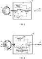
- FIG. 4 illustrates an integrated interrogator 34 according to the invention that measures the responses of at least two sensors coupled to the RFID sensor 37.
- the integrated interrogator 34 comprises a digital data reader 36 that reads the digital data from the memory chip of the RFID sensor 37.
- the memory chip comprises at least two sensing inputs, which are read by the integrated interrogator 34 for interrogation of the RFID sensor 37.
- Analog sensors 33 and 35 are connected to the inputs of the RFID sensor 37.
- the analog sensor 33 is a resistance sensor
- the analog sensor 35 is a capacitance sensor.
- a reader 40 monitors resistance of the analog sensor 33, and a reader 42 monitors capacitance of the connected analog sensor 35. Both the sensors 33 and 35 are coupled to a memory chip 39.
- the combination of the measured sensing parameters (resistance and capacitance) provides enhanced ability of the digital RFID sensor 37 to operate as a selective sensor for detection and quantitation of environmental parameters of interest (e.g. vapors concentrations, temperature, pressure, etc.) in the presence of high levels of interferences.
- the integrated interrogator 34 comprises a reader antenna 41 that recieves and transmits a signal from th RFID sensor 37 and the integrated interrogator 34 operatively coupled to the RFID sensor 37.
- three analog sensors arecoupled to a memory chip 39, where a first sensor measures resistance, a second sensor measures capacitance, and a third sensor measures inductance of the sensing material, such as sensing film, deposited on the sensors.
- the type of the sensing film deposited on the three sensors is same or different.
- the changes in measurable dielectric properties of the sensing film from these sensors are correlated to the physical, chemical or biological characteristic of the environment.
- there is one analog sensor connected to the memory chip 39 where the single sensor measures resistance, capacitance, and inductance of the sensing film deposited on the sensor.
- Sensor impedance spectra are processed to extract several spectral parameters such as F p , Z p , F 1 , or F 2 and others.
- the sensor impedance spectrum is transmitted to the central computing center for processing.
- the central computing center analyzes at least a portion of the impedance spectrum or spectral features using steady state or dynamic responses from the impedance reader.
- the steady state sensor response is a response from the sensor over a determined period of time, where the response does not appreciably change over the measurement time.
- the dynamic sensor response is a response from the sensor upon a sudden change in the measured environmental parameter (temperature, pressure, chemical concentration, biological concentration, etc.)
- the dynamic sensor response significantly change over the measurement time.
- measurements of dynamic sensor response over time produce dynamic signature of response.
- the dynamic signature of the response include average response slope, average response magnitude, largest positive slope of signal response, largest negative slope of signal response, average change in signal response, maximum positive change in signal response, and maximum negative change in signal response.
- the central computing center analyzes the full impedance spectrum using multivariate analysis.
- 'multivariate analysis' refers to an analysis of signals where one or more sensors produce multiple response signals that may or may not be substantially correlated with each other.
- the multiple response signals from the sensors are analyzed using multivariate analysis tools to construct response patterns of exposures to different environmental conditions, such as, pressure, temperature, liquids, biological species, and gases.
- multivariate analysis tools include canonical correlation analysis, regression analysis, nonlinear regression analysis, principal components analysis, discriminate function analysis, multidimensional scaling, linear discriminate analysis, logistic regression, or neural network analysis.
- the central computing center analyzes full impedance spectrum or spectral features using responses from the RFID sensor and its neighboring sensors.
- the central computing center is remotely located with respect to the integrated interrogator.
- the impedance spectrum or sensor parameters areanalyzed at a remote location away from the location of the RFID sensor.
- Non-limiting examples of such multivariate analyses are described in U.S. Patent Application, Serial No. 12/118,950 entitled “Methods and systems for calibration of RFID sensors", which is incorporated herein by reference.
- the integrated interrogator provides flexibility to the system because it can operate using multiple standards for reading digital data.
- standards include ISO 7816, ISO 14443, ISO 15693, ISO 18000, ISO 11784, ISO 11785.
- ISO 7816 is the standard for contact chip cards.
- ISO 7816-1 describes electrical and mechanical issues; ISO 7816-2 describes size, order and functionality of contact areas of the card and position of magstripe, if equipped with.
- ISO 14443 is the standard for contactless proximity cards operating at 13.56 MHz in up to 5 inches distance.
- ISO 15693 is the standard for contactless vicinity cards, such as cards that can be read from a greater distance as compared to proximity cards.
- ISO 15693 systems operate at a 13.56 MHz frequency and offer maximum read distance of 1-1.5 meters.
- ISO 18000 is the standard for item management air interface, including: ISO 18000-1 for generic parameters for air interface for global interface; ISO 18000-2 for parameters for air interface that operate at less than about 135 kHz; ISO 18000-3 for parameters for air interface at 13.56 MHz; ISO 18000-4 for parameters for air interface at 2.45 GHz; ISO 18000-5 for parameters for air interface at 5.8 GHz; ISO 18000-6 for parameters for air interface at 860- 930 MHz; and ISO 18000-7 for parameters for air interface at 433 MHz.
- ISO 11784 and ISO 11785 are standards for the radio-frequency identification of animals.
- ISO 11784 describes the code structure and the information content of the codes stored in the transponder.
- ISO 11785 describes the technical concept for the radio-frequency identification of animals, such as the characteristics of the transmission protocols between transponder and transceiver. Any other protocols of reading digital data from RFID tags can be also be used.
- the methods and systems enable determination of sensor parameters while maintaining low noise levels.
- the spectrum parameters are determined, with minimized uncertainty for further multivariate analysis by scanning the frequency range with a constant predetermined resolution.
- the number of waveforms ranges from 1 to 10000, and the number of scans ranges from 1 to 10000.
- the waveforms are averaged if the number of waveforms is more than 2.
- Scans are averaged if the number of scans is more than 2.
- a function such as a mathematical function, is applied to fit the resonance portion of the scan. In one embodiment, the mathematical function is applied to fit the resonance portion of the scan that comprises 35 percent or less of the total data points in the scan.
- the function may be applied to fit the resonance portion of the scan that comprises a Lorentzian lineshape fit or a baseline-corrected Lorentzian lineshape fit. Peak positions and magnitude of the peaks may be extracted using the mathematical function.
- Impedance spectrum may be measured with the constant or variable scan speed across a frequency range. The variable scan speed across the frequency range may be used to reduce measurement noise while scanning over a resonance frequency range. Impedance spectrum may be measured with a constant or variable scan frequency resolution across the frequency range. The variable frequency resolution across frequency range may be used to reduce measurement noise over scanning over a resonance frequency range.
- the integrated interrogator may enable low-power consumption operation.
- the components of the integrated interrogator are able to operate using a battery source or an energy-harvesting source.
- energy-harvesting sources include supercapacitors, sources based on ambient light, sources based on human motion, sources based on industrial vibration, sources based on thermal energy (human and industrial) or sources based on radio frequency energy from cell phones.
- the impedance reader is a part of a wireless system, such as a personal computer, personal digital assistant (PDA), or cell phone.
- the impedance reader provides near-field communication ability.
- NFC near field communication
- the term “near field communication (NFC)” means a short-range wireless communication technology in a frequency range of 3 MHz to about 30 MHz (known as high frequency communication), which enables the exchange of data between devices which may be either in contact, or at a distance of up to about 1 m.
- FIGS. 5-8 illustrate examples of relative frequency ranges that are used for integrated interrogation of a RFID sensor.
- sensing measurements of impedance spectrum may be performed at frequencies close to the frequency of operation of the digital portion of the reader where the digital portion of the reader operates in accordance with communication standards.
- sensing measurements are performed by scanning lower or higher frequencies compared to the frequency band that is used for reading of digital information from the RFID sensor.
- Frequency scanning is performed at different radio frequency (RF) power levels according to the power level permitted by the regulatory limits (e.g. FCC limits) in the frequency band.
- the frequency scanning time is reduced for frequency bands that permit a higher RF power level, while maintaining the same signal-to-noise ratio for the impedance measurement over the entire frequency range.
- Frequency scanning for measurements of sensing response may be performed at a constant rate across a desired frequency band or at a variable scanning rate with an RF power level adjusted to match the regulatory limit in a particular frequency range
- abscissa 46 represents frequency and ordinate 48 represents RF power level.
- the sensing or analog measurements may be performed by scanning frequencies 50 across the frequency band 52 that is used for reading digital information from the RFID sensor.
- sensing measurements may be performed by scanning lower frequencies 54 compared to the frequency band 56 that is used for reading of digital information from the RFID sensor.
- sensing measurements may be performed by scanning higher frequencies 58 compared to the frequency band 60 that is used for reading the digital information from the RFID sensor.
- the scanning may be performed at two different RF power levels 62 and 64.
- the power levels 62 and 64 are selected according to the power levels permitted by the regulatory limits in the corresponding frequency bands 66 and 68, respectively.
- the frequency band 70 is used in this example for reading the digital information from the RFID sensor. Using the example of FIG. 8 , the frequency scanning time may be reduced for frequency bands that permit a higher RF power level, while maintaining the same signal-to-noise ratio for the impedance measurement over the entire frequency range.
- the relative frequency ranges for the step of sensing and acquiring digital information may vary as shown in FIGS. 5-8 .
- the step of sensing is performed at scanning frequencies within 10 GHz of the frequency band of the digital reader.
- the scanning frequency range of the sensor response reader may be in a range from about 100 kHz to 25 GHz.
- the sensing may be performed at scanning frequencies within 10 MHz of the frequency band of the digital reader.
- the range of interest for the scanning frequency is about 13 MHz with a scan range of about 10 MHz.
- a scanning frequency range of the sensor response reader or impedance reader is from about 3 to 25 MHz.
- a sensing portion of the sensor RFID tag has an antenna that operates in one frequency range and a digital portion of the RFID tag has another antenna that operates in another frequency range.
- FIG. 9 illustrates a method for acquiring analog and digital data from a RFID sensor in a given environment.
- at block 72 at least two of a physical, chemical or biological characteristics of the environment are simultaneously sensed at least in part by measuring an impedance spectrum of a resonant antenna structure of the RFID sensor.
- analog and/or digital information relating to the tag of the RFID sensor is acquired.
- the digital information may be acquired from a memory chip of the RFID sensor.
- the order of blocks 72 and 74 may be reversed. That is, the analog and/or digital information relating to the RFID sensor may be acquired first, and the analog information relating to the characteristics of the environment being sensed may be acquired later.
- sensing and information gathering relating to the RFID tag may be performed at least periodically by the integrated interrogator.
- the steps of sensing the characteristics of the environment, and acquiring the digital information may be performed simultaneously, periodically or sequentially.
- the acquired impedance spectrum may be analyzed at a remote location, such as a remotely located central computing center.
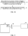
- FIG. 10 illustrates a method not covered by the claimed invention for acquiring sensor data from a RFID sensor disposed in an environment, where the RFID sensor is receiving input from at least two analog sensors is provided.
- the method comprises measuring responses of the at least two analog sensors coupled to the RFID tag of the RFID sensor. Receieving the input from the two analog sensors improves the accuracy, precision, or both, of the RFID sensor.
- At block 76 at least two of a physical, chemical or biological characteristics of the environment are determined by measuring resistance and capacitance of at least one sensor structure connected to a memory chip of the RFID tag.
- the method comprises monitoring a resistance of at least one of the analog sensors relative to the environmental characteristics, and monitoring a capacitance of at least one of the analog sensors relative to environmental characteristics.
- the analog signals of resistance and capacitance are converted into digital information related to resistance and capacitance.
- this digital information relating to at least one of the RFID sensors is acquired from a memory chip of the RFID sensor.
- the resistance and the capacitance are analyzed to measure at least two of the physical, chemical or biological characteristics. The steps of analyzing the resistance and capacitance may be performed simultaneously to reduce or eliminate interference effects from the sensor data.
- a method for measuring at least three responses from a sensor or sensors connected to a RFID tag is described. At least two of a physical, chemical or biological characteristics of the environment are determined by measuring resistance, inductance, and capacitance of at least one sensor structure coupled to a memory chip of the RFID tag. In the memory chip, the analog signals of resistance, inductance, and capacitance are converted into digital information related to resistance, inductance, and capacitance. This digital information relating to at least one of the RFID sensors is acquired from a memory chip of the RFID sensor. The resistance, inductance, and capacitance may be analyzed to measure at least two of the physical, chemical or biological characteristics. The steps of analyzing the resistance, the inductance, and the capacitance may be performed simultaneously to reject effects of interferences from measured sensor response.
- FIG. 11 An example of an application of the integrated interrogator 80 is shown in FIG. 11 .
- an RFID sensor 82 is disposed in or on a disposable bioprocess component 84.
- the RFID sensor 82 is in wireless communication with a reader antenna 88.
- the reader antenna 88 is, in tum, in operative association with the integrated interrogator 80.
- the reader antenna 88 and the integrated interrogator 80 may be in operative association using physical contact (wired connection).
- the reader antenna 88 and the sensor 82 may be physically coupled using wired connection.
- the reader antenna 88 and the sensor 82 may wirelessly communicate.
- the disposable component 84 may be manufactured for disposable bioprocesses such as pharmaceutical, biopharmaceutical manufacturing and other processes.
- the disposable component 84 may be used in a pharmaceutical production process and may include components such as, but not limited to, bioreactors, mixers, product transfer lines, connectors, filters, chromatography columns and centrifuges.
- the RFID sensor 82 in conjunction with integrated interrogator 80, enables the in-line manufacturing, monitoring and control of the bioprocess.
- FIG. 12 is a schematic diagram of an example of an interrogation system of the invention for interrogating two or more RFID sensors using an integrated interrogator 90.
- the integrated interrogator 90 may interrogate digital and analog signals from a plurality of sensors, generally represented by the reference numerals 92 and 94.
- the dashed line 96 represents a plurality of sensors present between the sensors 92 and 94.
- the plurality of sensors 96, and the sensors 92 and 94 may have similar or different structures depending on the particular environmental parameter that these sensors are designed to sense.
- the information from the different sensors 92, 94 and 96 may be combined to provide sensor responses corresponding to different environmental parameters.
- some sensors may be designed to measure environmental parameters, such as temperature or pressure, while the other sensors may be designed for other applications, such as analyte detection.
- such an integrated interrogator 90 may include, for example, either a switch or a multiplexer.
- the multiplexer may select one or more analog and/or digital input signals from the determined number of sensors, and forward the selected input to a central computing center 98.
- the integrated interrogator 90 may be configured to analyze the various analog and digital inputs from the different sensors 92, 94 and 96, and may not require the central computing center 98.
- FIG. 13 illustrates an arrangement having a plurality of interrogation systems 100.
- Each of the interrogation systems 100 may comprise one or more RFID sensors, and an integrated interrogator. Some of the plurality of interrogation systems 100 may share a common integrated interrogator.
- Interrogation systems 100 are operatively associated with each other by a central computing center 102. In this way, the integrated interrogators of the plurality of interrogation systems 100 may advantageously have access to information provided by other sensors.
- the interrogation systems 100 may use a communication module in their integrated interrogator to communicate with the central computing center 102.
- the central computing center 102 may be remotely located with respect to the interrogation systems 100. In this embodiment, the impedance spectrum or sensor parameters may be analyzed at a remote location away from the location of the RFID sensors.
- Frequency scanning for measurements of sensing response may be performed at a constant rate across a desired frequency band or at a variable scanning rate with an RFpower level adjusted to match the regulatory limit in a particular frequency range.
- Measurements of the impedance of RFID sensors were performed using a network analyzer (Agilent Technologies, Inc. Santa Clara, CA) under a computer control using LabVIEW.
- the analyzer was used to scan the frequencies over the range of interest (typically centered at 13 MHz with a scan range of ⁇ 10 MHz) and to collect the impedance response from the RFID sensor.
- a multichannel electronic signal multiplexer was built to operate with the analyzer for measurements of two or more RFID sensors at once. The collected impedance spectrum was analyzed using Excel (MicroSoft Inc.
- a Texas Instruments RFID tag was used.
- the tag was coated with a polyaniline sensing film to fabricate a pH sensor.
- the digital ID of the tag was read with the writer/reader as defined above to be E007 000 02BE 960C.
- the writer/reader was used to write additional digital data into the memory chip.
- the written data was GE GRC RFID Sensor #323.
- the writer/reader was further used in the reading mode to read digital portion from the sensor and analog portion (impedance).
Landscapes
- Engineering & Computer Science (AREA)
- Physics & Mathematics (AREA)
- Health & Medical Sciences (AREA)
- Microelectronics & Electronic Packaging (AREA)
- General Physics & Mathematics (AREA)
- Theoretical Computer Science (AREA)
- Computer Hardware Design (AREA)
- Toxicology (AREA)
- Electromagnetism (AREA)
- General Health & Medical Sciences (AREA)
- Artificial Intelligence (AREA)
- Computer Vision & Pattern Recognition (AREA)
- Arrangements For Transmission Of Measured Signals (AREA)
- Near-Field Transmission Systems (AREA)
Description
- The invention relates generally to sensors, and more particularly to systems and methods for interrogating radio frequency identification (RFID) sensors.
- RADISLAV A. POTYRAILO ET AL: "RFID sensors based on ubiquitous passive 13.56MHz RFID tags and complex impedance detection", WIRELESS COMMUNICATIONS AND MOBILE COMPUTING, vol. 9, no. 10, 1 October 2009 (2009-10-01), pages 1318-1330 discloses RFID sensors for sensing applications.
- Generally, RFID readers are used to obtain digital data from RFID tags. Digital data may include, for example, digital identification of the tag, or any other information written and/or stored in a memory chip of the RFID tag. The RFID tags transmit electromagnetic signals at different relative levels of transmitted power at different times. Signals received by the RFID reader in combination with the transmitted relative power level of the received signals are employed to locate the RFID tags, and read the digital identification information from the RFID tag (e.g., from the memory chip or back-reflector structure of the RFID tag).
- When the RFID tags are used in RFID sensors, separate readers are used to read the analog (e.g. sensing parameters) and digital (e.g. tag ID, stored user information) data from the RFID sensors. In cases where digital data as well as analog data are obtained from the RFID sensors, two different readers need to be employed. Use of two different readers increases the complexity, size and cost of the system.
- Therefore, it is desirable to have an integrated interrogation system for RFID sensors that can read both digital and analog data from the RFID sensors.
- The present invention is defined in the accompanying claims.
- An integrated interrogator for a RFID sensor is provided. The integrated interrogator comprises a digital reader in communication with the RFID sensor, an impedance reader in communication with the RFID sensor, and one or more controllers that coordinate actions of the digital reader and the impedance reader.
- The invention according to claim 1 discloses an interrogation system for interrogation of one or more RFID sensors is provided. The interrogation system comprises a reader antenna (pick up coil) that recieves and transmits a signal from the RFID sensors, and an integrated interrogator operatively coupled to one or more of the RFID sensors. The integrated interrogator comprises an impedance reader that measures an impedance spectrum of the RFID sensors, a digital data reader that reads data from a memory chip of the RFID sensors, and a controller that coordinates actions of the sensor response reader and the digital reader, wherein the controller comprises an electronic switch operable to switch between analog and digital data acquisition from the impedance reader and the digital data reader, respectively.
- In another embodiment, a method for analog and digital data acquisition from one or more RFID sensors, disposed in an environment is provided. The method comprises sensing at least two of a physical, chemical or biological characteristic of the environment at least in part by measuring an impedance spectrum of a resonant antenna structure, and acquiring digital, or analog, or both digital and analog information relating to the RFID sensor.
- In another embodiment not covered by the claimed invention, a method for acquiring data from a RFID sensor, which is receiving input from at least two analog sensors, disposed in an environment, to improve the RFID sensor's accuracy, precision or a combination thereof is provided. The method comprises monitoring a resistance of at least one of the analog sensor relative to least one of a physical, chemical or biological characteristic of the environment, monitoring a capacitance of at least one of the analog sensors relative to least one of the physical, chemical or biological characteristic of the environment; and analyzing the resistance and capacitance.
- These and other features, aspects, and advantages of the invention will become better understood when the following detailed description is read with reference to the accompanying drawings in which like characters represent like parts throughout the drawings, wherein:
-
FIG. 1 is a schematic diagram of an example of an interrogation system for a RFID sensor comprising an integrated interrogator of the invention; -
FIG. 2 is a graph of measured impedance parameters of an embodiment of the RFID sensor of the invention; -
FIGS. 3-4 are schematic diagrams of examples of interrogation systems for RFID sensors comprising an integrated interrogator of the invention; -
FIGS. 5-8 are graphs of examples of relative frequency ranges for sensing analog and digital data using the integrated interrogator; -
FIGS. 9-10 are flow charts of the steps of example methods of the invention for measuring at least two of a physical, chemical or biological characteristics of the environment; -
FIG. 11 is a schematic diagram of a disposable bioprocess component using an RFID sensor, and an integrated interrogator for the RFID sensor; -
FIG. 12 is a schematic diagram of an example of an interrogation system of the invention for interrogation of a plurality of RFID sensors; -
FIG. 13 is a schematic diagram of an example of an interrogation system of the invention using a central computing center; -
FIG. 14 is a graph of example analog and digital data acquired using integrated interrogation of the invention; - The embodiments disclosed herein facilitate integrated interrogation of RFID sensors. The RFID sensors may be used to measure a variety of physical, chemical and biological parameters. The methods and systems for integrated interrogation may be used to collect both digital and analog signals from the RFID sensor to obtain digital or analog data (e.g. tag ID, end-user stored information, sensing information, any other digital information available from the tag) corresponding to the RFID tag of the RFID sensors, and analog data (e.g., sensing measurements, reflected power measurements) corresponding to the RFID sensors. The integrated interrogator comprises a digital reader in communication with the RFID sensor, an impedance reader in communication with a sensor, and one or more controllers that coordinate actions of the digital reader and the impedance reader. The digital reader is in communication with a memory chip of the RFID sensor. The digital reader is in communication with a memory chip of the RFID sensor, where the memory chip has at least two sensor inputs. In this embodiment according to the invention, at least one sensor input measures sensor resistance, and at least one input measures sensor capacitance. In one example, the impedance reader may be in communication with the sensor resonant antenna structure. The sensing measurements of the impedance of the RFID sensor (resonant antenna structure) may be performed at frequencies close to the frequency of operation of the digital portion of the integrated interrogator. The digital portion of the impedance reader operates in accordance with accepted communication standards.
- The RFID sensors are wireless sensors or wired sensors. The wireless RFID sensors are wirelessly coupled to the integrated interrogator. The wired sensors are electrically coupled using wires to the integrated interrogator or other components of the sensor system. In embodiments where the sensor is a wireless sensor, the impedance reader isin communication with the sensor resonant antenna structure, or sensor antenna. In embodiments where the sensor is a wired sensor, the impedance reader is in communication with the sensor.
- In one embodiment, the RFID tag of the RFID sensor is a passive tag. A passive RFID tag does not need a battery for its function and comprises a memory chip that is coupled to the sensor antenna. In one embodiment, the integrated interrogator is coupled to a finite electrical power source, which is self-contained (i.e., internal) within the integrated interrogator, such as a relatively small portable battery consisting of one or more disposable dry cells or rechargeable cells. Alternatively, the integrated interrogator is operable using a power supply that is hard wired to a remote electrical power source, such as an electric grid. Alternatively, the integrated interrogator is coupled to a finite electrical power harvesting source, such as a super capacitor, or other.
- The distance between the passive RFID tag and the integrated interrogator is governed by the design parameters that include type of sensor (e.g. wired orwireless), operating frequency, RF power level, receiving sensitivity of the integrated interrogator, size of sensor antenna, data rate from the RFID sensor, communication protocol, and power requirements of the memory chip.
- The integrated interrogator may provide sensor information to a central computing center using wireless communication. The integrated interrogator may be in communication with the central computing center via a network for processing the digital and analog data. The central computing center may be directly or indirectly coupled to one or more sensors (or neighboring sensors). In this way, the integrated interrogator may advantageously have access to information provided by other sensors. The neighboring sensors may measure same or different environmental parameters.
- Non-limiting examples of a central computing center not covered by the claimed invention, include a central hub or a cloud- computing cluster. As used herein, the term "cloud computing" is an Internet-based computing, whereby shared resources, software and information are provided to computers and other devices on-demand. A central processor might be used to generate detailed response models. Cloud computing may reduce the cost and capital expenditure. In addition, cloud computing may provide location independence by enabling the users to access the systems using a web browser regardless of their location or what device they are using (e.g., personal computer, or mobile). In one embodiment not covered by the claimed invention, a cloud computing cluster would allow a user or automated system to dynamically evolve the model based on, for example, changing ambient noise parameters. Non- limiting examples of such ambient noise parameters include temperature, humidity or pressure. In some applications, these and other environmental parameters may be parameters of measurement interest. Values of ambient noise parameters may be provided using one or more sensors. The detailed response model may evolve based on neighbor sensors that provide similar or different sensing information about other measured parameters.
- As illustrated in
FIG. 1 , anintegrated interrogator 10 is operatively coupled to theRFID sensor 12. Theintegrated interrogator 10 comprises a digital reader/writer 14 in communication with theRFID sensor 12, and a reader antenna (pick up coil) 18. The terms "digital reader/writer" and "digital reader" may be used interchangeably throughout the application. Theinterrogator 10 further comprises animpedance reader 16 in communication with thereader antenna 18, and one or more controllers that coordinate actions of the digital reader/writer 14 and theimpedance reader 16. Thereader antenna 18 may generate afield 17 to interact with theRFID sensor 12. Thefield 17 may be a magnetic field, or an electric field. - The digital reader/
writer 14 performs both read and write functions. The digital reader/writer 14 reads and/or writes data from an integrated circuit (IC) memory chip of theRFID sensor 12. In one embodiment, thedigital reader 14 may read the digital data from the digital portion of the RFID tag of thesensor 12 and write digital data into a writable memory of the RFID tag. The writable memory of theRFID sensor 12 may be the IC memory chip. In another embodiment, the digital reader may read the digital data from a digital portion of theRFID sensor 12 that does not have a re-writable memory. For example, in case of a surface- acoustic wave RFID tag, the non-writable memory of the RFID tag may be a set of reflectors. - In one embodiment, the memory chip may be an integrated circuit memory chip or a memory chip based on read-only memory such as a surface acoustic wave device. The memory chip may be coupled to the
sensor 12. The digital reader/writer 14 may be a single-frequency, single-protocol reading/writing device, or a multi-frequency, multi-protocol reading/writing device. Examples of single-frequency devices are devices that interrogate RFID tags only at a single given ISM (Industrial-Scientific-Medical) frequency range or at a frequency below 400 kHz. Non-limiting examples include frequencies of 120 kHz, 125 kHz, 128 kHz, 135 kHz, 6.78 MHz, 13.56 MHz, 27.125 MHz, 40.68 MHz, 433.92 MHz, 869.0 MHz, 915.0 MHz, 2.45 GHz, 5.8 GHz, 24.125 GHz. Thedigital reader 14 isconstructed for multi-frequency operation, where a reader can read digital information from different tags designed to operate at different frequencies. Each frequency has a frequency range around which thedigital reader 14 operates to determine the presence of an RFID tag and to read the digital content of the RFID tag. In one example, a digital reader for 13.56 MHz interrogates an RFID tag using a frequency of 13.553 MHz, and detects the modulated output from the RFID tag between 13.11 MHz and 13.553MHz as well as between 13.553MHz and 14.01MHz. Standard protocols may be used for reading digital data from theRFID sensor 12. - The
impedance reader 16 measures impedance spectrum of the resonance sensor circuit of theRFID sensor 12. In addition to measuring the impedance spectrum, theimpedance reader 16 may also perform analysis of the measured spectrum. Alternatively, the impedance spectrum may be transmitted to a remote location or a central computing center, and the analysis of the measured spectrum may be performed in the central computing center. The impedance spectrum may be analyzed simultaneously using various parameters for analysis, such as, the frequency of the maximum of the real part of the impedance (Fp), the magnitude of the real part of the impedance (Zp), the resonant frequency of the imaginary part of the impedance (F1) , and the anti-resonant frequency of the imaginary part of the impedance (F2) , signal magnitude (Z1) at the resonant frequency of the imaginary part of the complex impedance (F1) , signal magnitude (Z2) at the anti-resonant frequency of the imaginary part of the complex impedance (F2) , and zero-reactance frequency (Fz, frequency at which the imaginary portion of impedance is zero). Other parameters may be simultaneously measured using the entire complex impedance spectra, for example, quality factor of resonance, phase angle, and magnitude of impedance. Multivariable response parameters are described inU.S. Patent Application, Serial No. 12/118,950 entitled "Methods and systems for calibration of RFID sensors", which is incorporated herein by reference. - A
controller 19 may be used to coordinate actions of thedigital reader 14 and theimpedance reader 16. For example, thecontroller 19 may be used to control the order/sequence in which thedigital reader 14 and theimpedance reader 16 measure/read from theRFID sensor 12. In one embodiment, the controller may be configured to receive input from a user to determine the order for thedigital reader 14 and theimpedance reader 16 to measure/read data from theRFID sensor 12. - Although not shown, a communication module may be operatively coupled to the
interrogator 10. The communication module may be used to communicate with external devices, such as aprocessor 20, or a network. Non-limiting examples of the communication module include wireless communication modules and USB communication modules. In one example, the communication module may be a component of thecontroller 19. - The
processor 20 may process the analog and digital data received from theRFID sensor 12. Theprocessor 20 may be either external or internal to theintegrated interrogator 10. That is, theprocessor 20 may be either part of theintegrated interrogator 10 or may be separately provided along with theintegrated interrogator 10. In one example, theimpedance reader 16 may be a component of theinternal processor 20. Theprocessor 20 may be in communication with theintegrated interrogator 10 directly or via a network. Theprocessor 20 may be locally or remotely located with respect to theintegrated interrogator 10. For example, a remotely locatedprocessor 20 may be present in a remotely located central computing center with respect to theintegrated interrogator 10. In addition to processing the sensor data (analog and digital data), theprocessor 20 may be configured to display the processed data. Theprocessor 20 may be configured to receive user inputs and transmit the received inputs to theintegrated interrogator 10. For example, theprocessor 20 may receive user inputs regarding the sequence for collecting analog and digital data; theprocessor 20 may then pass the inputs to the controller 19 (or the communication module). - The combination of components of sensor circuit result in the generation of an impedance response formed by resonant circuit parameters such as Fp, Zp, F1, Z2 and any other generated from the RFID tag of the RFID sensor.
FIG. 2 illustrates examples of real and imaginary portions of the impedance response spectrum of the sensor. As illustrated by thecurve 21, the real part of the impedance includesparameters F p 24 andZ p 25. Theparameter F p 24 represents the frequency of the maximum of the real part of the impedance, and theparameter Z p 25 represents the magnitude of the real part of the impedance. Similarly, as illustrated by thecurve 22, the imaginary part of the impedance includesF 1 26,F 2 28,F z 27,Z 1 29, andZ 2 31. Theparameter F 1 26 represents resonant frequency of the imaginary part of the impedance, and theparameter F 2 28 represents anti-resonant frequency of the imaginary part of the impedance. The parameters F1 and F2 are related to different components of the equivalent circuit. Theparameter Z 1 31 represents signal magnitude at the resonant frequency of the imaginary part of thecomplex impedance F 1 26. Theparameter Z 2 31 represents signal magnitude at the anti-resonant frequency of the imaginary part of thecomplex impedance F 2 28. Theparameter F z 27 represents the zero-reactance frequency. Additional non-limiting examples of the sensor parameters include parameters that can be extracted from the response of the equivalent circuit of the RFID sensor, the quality factor of resonance, phase angle, and magnitude of impedance of the resonance circuit response of the RFID sensor, and others known in the art. The difference betweenF 1 26 andF 2 28 is related to peak width. In this example, sinceF 1 26 andF 2 28 are related to different components of an equivalent circuit,F 1 26 andF 2 28 are not correlated. Peak symmetry may be affected by changes in impedance. Other parameters can be measured using the entire impedance spectrum, for example, using the quality factor of resonance, phase angle, and magnitude of impedance. - The sensor may sense at least two of chemical, biological or physical parameters. In one embodiment, a sensing material, such as a sensing film, is disposed on the sensor antenna. In this embodiment, any changes in the film affect the sensor response. In one embodiment, an antenna is made in part from material that is responsive to environment. In this embodiment, the antenna is sensitive to the environment.
- Two different approaches are used for sensing. In one approach, a sensing material is disposed on the sensor antenna to alter the impedance response of the sensor. Any changes in the sensing material film may affect the sensor response. In another approach, a complementary sensor is attached across an antenna and an optional memory chip. The complementary sensor is used to alter sensor impedance response. Any changes in the complementary sensor that is attached to the sensor antenna may affect the sensor response. Examples of such complementary sensors are described in
U.S. Patent Application, Serial No. 12/118,950 , entitled "Methods and systems for calibration of RFID sensors", which is incorporated herein by reference. - Referring to
FIG. 3 , aswitch 32 is provided in theintegrated interrogator 30 for switching between analog and digital data acquisition. Theintegrated interrogator 30 uses theswitch 32 to read digital data (e.g., from the IC memory chip), and analog data (e.g., impedance spectrum of the resonant sensor circuit) in rapid sequence. In one embodiment, theswitch 32 may be controlled using thecontroller 19. Theswitch 32 is a component of thecontroller 19. Theswitch 32 may be physically external from thecontroller 19, while the switches' function is still controlled by thecontroller 19. -
FIG. 4 illustrates anintegrated interrogator 34 according to the invention that measures the responses of at least two sensors coupled to theRFID sensor 37. Theintegrated interrogator 34 comprises adigital data reader 36 that reads the digital data from the memory chip of theRFID sensor 37. The memory chip comprises at least two sensing inputs, which are read by theintegrated interrogator 34 for interrogation of theRFID sensor 37.Analog sensors 33 and 35 are connected to the inputs of the RFID sensor 37.The analog sensor 33 is a resistance sensor, and theanalog sensor 35 is a capacitance sensor. Although not shown, a single sensor that produces both resistance and capacitance measurable responses iscoupled to the input of theRFID sensor 37. As illustrated, in theintegrated interrogator 34, areader 40 monitors resistance of the analog sensor 33, and areader 42 monitors capacitance of theconnected analog sensor 35. Both thesensors 33 and 35 are coupled to amemory chip 39. The combination of the measured sensing parameters (resistance and capacitance) provides enhanced ability of thedigital RFID sensor 37 to operate as a selective sensor for detection and quantitation of environmental parameters of interest (e.g. vapors concentrations, temperature, pressure, etc.) in the presence of high levels of interferences. Theintegrated interrogator 34 comprises areader antenna 41 that recieves and transmits a signal fromth RFID sensor 37 and theintegrated interrogator 34 operatively coupled to theRFID sensor 37. In one embodiment, although not shown, three analog sensors arecoupled to amemory chip 39, where a first sensor measures resistance, a second sensor measures capacitance, and a third sensor measures inductance of the sensing material, such as sensing film, deposited on the sensors. The type of the sensing film deposited on the three sensors is same or different. The changes in measurable dielectric properties of the sensing film from these sensors are correlated to the physical, chemical or biological characteristic of the environment. Alternatively, there is one analog sensor connected to thememory chip 39, where the single sensor measures resistance, capacitance, and inductance of the sensing film deposited on the sensor. - Sensor impedance spectra are processed to extract several spectral parameters such as Fp, Zp, F1, or F2 and others. The sensor impedance spectrum is transmitted to the central computing center for processing. In one example, the central computing center analyzes at least a portion of the impedance spectrum or spectral features using steady state or dynamic responses from the impedance reader. The steady state sensor response is a response from the sensor over a determined period of time, where the response does not appreciably change over the measurement time. Thus, measurements of steady state sensor response over time produce similar values. The dynamic sensor response is a response from the sensor upon a sudden change in the measured environmental parameter (temperature, pressure, chemical concentration, biological concentration, etc.) Thus, the dynamic sensor response significantly change over the measurement time. Thus, measurements of dynamic sensor response over time produce dynamic signature of response. Non-limiting examples of the dynamic signature of the response include average response slope, average response magnitude, largest positive slope of signal response, largest negative slope of signal response, average change in signal response, maximum positive change in signal response, and maximum negative change in signal response.
- In one example, the central computing center analyzes the full impedance spectrum using multivariate analysis. As used herein, 'multivariate analysis' refers to an analysis of signals where one or more sensors produce multiple response signals that may or may not be substantially correlated with each other. The multiple response signals from the sensors are analyzed using multivariate analysis tools to construct response patterns of exposures to different environmental conditions, such as, pressure, temperature, liquids, biological species, and gases. Non-limiting examples of multivariate analysis tools include canonical correlation analysis, regression analysis, nonlinear regression analysis, principal components analysis, discriminate function analysis, multidimensional scaling, linear discriminate analysis, logistic regression, or neural network analysis. In another example, the central computing center analyzes full impedance spectrum or spectral features using responses from the RFID sensor and its neighboring sensors. In one embodiment, the central computing center is remotely located with respect to the integrated interrogator. In this embodiment, the impedance spectrum or sensor parameters areanalyzed at a remote location away from the location of the RFID sensor. Non-limiting examples of such multivariate analyses are described in
U.S. Patent Application, Serial No. 12/118,950 entitled "Methods and systems for calibration of RFID sensors", which is incorporated herein by reference. - The integrated interrogator provides flexibility to the system because it can operate using multiple standards for reading digital data. Non-limiting examples of standards include ISO 7816, ISO 14443, ISO 15693, ISO 18000, ISO 11784, ISO 11785. ISO 7816 is the standard for contact chip cards. ISO 7816-1 describes electrical and mechanical issues; ISO 7816-2 describes size, order and functionality of contact areas of the card and position of magstripe, if equipped with. ISO 14443 is the standard for contactless proximity cards operating at 13.56 MHz in up to 5 inches distance. ISO 15693 is the standard for contactless vicinity cards, such as cards that can be read from a greater distance as compared to proximity cards. ISO 15693 systems operate at a 13.56 MHz frequency and offer maximum read distance of 1-1.5 meters. ISO 18000 is the standard for item management air interface, including: ISO 18000-1 for generic parameters for air interface for global interface; ISO 18000-2 for parameters for air interface that operate at less than about 135 kHz; ISO 18000-3 for parameters for air interface at 13.56 MHz; ISO 18000-4 for parameters for air interface at 2.45 GHz; ISO 18000-5 for parameters for air interface at 5.8 GHz; ISO 18000-6 for parameters for air interface at 860- 930 MHz; and ISO 18000-7 for parameters for air interface at 433 MHz. ISO 11784 and ISO 11785 are standards for the radio-frequency identification of animals. ISO 11784 describes the code structure and the information content of the codes stored in the transponder. ISO 11785 describes the technical concept for the radio-frequency identification of animals, such as the characteristics of the transmission protocols between transponder and transceiver. Any other protocols of reading digital data from RFID tags can be also be used.
- The methods and systems enable determination of sensor parameters while maintaining low noise levels. The spectrum parameters are determined, with minimized uncertainty for further multivariate analysis by scanning the frequency range with a constant predetermined resolution. The number of waveforms ranges from 1 to 10000, and the number of scans ranges from 1 to 10000. The waveforms are averaged if the number of waveforms is more than 2. Scans are averaged if the number of scans is more than 2. A function, such as a mathematical function, is applied to fit the resonance portion of the scan. In one embodiment, the mathematical function is applied to fit the resonance portion of the scan that comprises 35 percent or less of the total data points in the scan. In one embodiment, the function may be applied to fit the resonance portion of the scan that comprises a Lorentzian lineshape fit or a baseline-corrected Lorentzian lineshape fit. Peak positions and magnitude of the peaks may be extracted using the mathematical function. Impedance spectrum may be measured with the constant or variable scan speed across a frequency range. The variable scan speed across the frequency range may be used to reduce measurement noise while scanning over a resonance frequency range. Impedance spectrum may be measured with a constant or variable scan frequency resolution across the frequency range. The variable frequency resolution across frequency range may be used to reduce measurement noise over scanning over a resonance frequency range.
- In certain embodiments, the integrated interrogator may enable low-power consumption operation. The components of the integrated interrogator are able to operate using a battery source or an energy-harvesting source. Non-limiting examples of energy-harvesting sources include supercapacitors, sources based on ambient light, sources based on human motion, sources based on industrial vibration, sources based on thermal energy (human and industrial) or sources based on radio frequency energy from cell phones.
- In certain embodiments, the impedance reader is a part of a wireless system, such as a personal computer, personal digital assistant (PDA), or cell phone. The impedance reader provides near-field communication ability. As used herein, the term "near field communication (NFC)" means a short-range wireless communication technology in a frequency range of 3 MHz to about 30 MHz (known as high frequency communication), which enables the exchange of data between devices which may be either in contact, or at a distance of up to about 1 m.
-
FIGS. 5-8 illustrate examples of relative frequency ranges that are used for integrated interrogation of a RFID sensor. In some embodiments, sensing measurements of impedance spectrum may be performed at frequencies close to the frequency of operation of the digital portion of the reader where the digital portion of the reader operates in accordance with communication standards. In other embodiments, sensing measurements are performed by scanning lower or higher frequencies compared to the frequency band that is used for reading of digital information from the RFID sensor. - Frequency scanning is performed at different radio frequency (RF) power levels according to the power level permitted by the regulatory limits (e.g. FCC limits) in the frequency band. The frequency scanning time is reduced for frequency bands that permit a higher RF power level, while maintaining the same signal-to-noise ratio for the impedance measurement over the entire frequency range. Frequency scanning for measurements of sensing response may be performed at a constant rate across a desired frequency band or at a variable scanning rate with an RF power level adjusted to match the regulatory limit in a particular frequency range
- As illustrated in
FIG. 5 ,abscissa 46 represents frequency andordinate 48 represents RF power level. The sensing or analog measurements may be performed by scanningfrequencies 50 across thefrequency band 52 that is used for reading digital information from the RFID sensor. In the example shown inFIG. 6 , sensing measurements may be performed by scanninglower frequencies 54 compared to thefrequency band 56 that is used for reading of digital information from the RFID sensor. In the example shown inFIG. 7 , sensing measurements may be performed by scanninghigher frequencies 58 compared to thefrequency band 60 that is used for reading the digital information from the RFID sensor. In the example shown inFIG. 7 , the scanning may be performed at two differentRF power levels power levels corresponding frequency bands frequency band 70 is used in this example for reading the digital information from the RFID sensor. Using the example ofFIG. 8 , the frequency scanning time may be reduced for frequency bands that permit a higher RF power level, while maintaining the same signal-to-noise ratio for the impedance measurement over the entire frequency range. - The relative frequency ranges for the step of sensing and acquiring digital information may vary as shown in
FIGS. 5-8 . In one embodiment, the step of sensing is performed at scanning frequencies within 10 GHz of the frequency band of the digital reader. The scanning frequency range of the sensor response reader (impedance reader) may be in a range from about 100 kHz to 25 GHz. In one example, the sensing may be performed at scanning frequencies within 10 MHz of the frequency band of the digital reader. In one example, the range of interest for the scanning frequency is about 13 MHz with a scan range of about 10 MHz. A scanning frequency range of the sensor response reader or impedance reader is from about 3 to 25 MHz. To achieve the relative frequency ranges for the step of sensing and acquiring digital information that as shown inFIGS. 6 and 7 , a sensing portion of the sensor RFID tag has an antenna that operates in one frequency range and a digital portion of the RFID tag has another antenna that operates in another frequency range. -
FIG. 9 illustrates a method for acquiring analog and digital data from a RFID sensor in a given environment. Atblock 72, at least two of a physical, chemical or biological characteristics of the environment are simultaneously sensed at least in part by measuring an impedance spectrum of a resonant antenna structure of the RFID sensor. Atblock 74, analog and/or digital information relating to the tag of the RFID sensor is acquired. The digital information may be acquired from a memory chip of the RFID sensor. The order ofblocks -
FIG. 10 illustrates a method not covered by the claimed invention for acquiring sensor data from a RFID sensor disposed in an environment, where the RFID sensor is receiving input from at least two analog sensors is provided. The method comprises measuring responses of the at least two analog sensors coupled to the RFID tag of the RFID sensor. Receieving the input from the two analog sensors improves the accuracy, precision, or both, of the RFID sensor. Atblock 76, at least two of a physical, chemical or biological characteristics of the environment are determined by measuring resistance and capacitance of at least one sensor structure connected to a memory chip of the RFID tag. The method comprises monitoring a resistance of at least one of the analog sensors relative to the environmental characteristics, and monitoring a capacitance of at least one of the analog sensors relative to environmental characteristics. In the memory chip, the analog signals of resistance and capacitance are converted into digital information related to resistance and capacitance. Atblock 78, this digital information relating to at least one of the RFID sensors is acquired from a memory chip of the RFID sensor. The resistance and the capacitance are analyzed to measure at least two of the physical, chemical or biological characteristics. The steps of analyzing the resistance and capacitance may be performed simultaneously to reduce or eliminate interference effects from the sensor data. - In one embodiment not covered by the claimed invention, a method for measuring at least three responses from a sensor or sensors connected to a RFID tag is described. At least two of a physical, chemical or biological characteristics of the environment are determined by measuring resistance, inductance, and capacitance of at least one sensor structure coupled to a memory chip of the RFID tag. In the memory chip, the analog signals of resistance, inductance, and capacitance are converted into digital information related to resistance, inductance, and capacitance. This digital information relating to at least one of the RFID sensors is acquired from a memory chip of the RFID sensor. The resistance, inductance, and capacitance may be analyzed to measure at least two of the physical, chemical or biological characteristics. The steps of analyzing the resistance, the inductance, and the capacitance may be performed simultaneously to reject effects of interferences from measured sensor response.
- An example of an application of the
integrated interrogator 80 is shown inFIG. 11 . In this embodiment, anRFID sensor 82 is disposed in or on adisposable bioprocess component 84. - As represented by
arrows 86, theRFID sensor 82 is in wireless communication with areader antenna 88. Thereader antenna 88 is, in tum, in operative association with theintegrated interrogator 80. Thereader antenna 88 and theintegrated interrogator 80 may be in operative association using physical contact (wired connection). Thereader antenna 88 and thesensor 82 may be physically coupled using wired connection. Alternatively, thereader antenna 88 and thesensor 82 may wirelessly communicate. In one example, thedisposable component 84 may be manufactured for disposable bioprocesses such as pharmaceutical, biopharmaceutical manufacturing and other processes. For example, thedisposable component 84 may be used in a pharmaceutical production process and may include components such as, but not limited to, bioreactors, mixers, product transfer lines, connectors, filters, chromatography columns and centrifuges. In one example, theRFID sensor 82, in conjunction withintegrated interrogator 80, enables the in-line manufacturing, monitoring and control of the bioprocess. -
FIG. 12 is a schematic diagram of an example of an interrogation system of the invention for interrogating two or more RFID sensors using an integratedinterrogator 90. In one embodiment, theintegrated interrogator 90 may interrogate digital and analog signals from a plurality of sensors, generally represented by thereference numerals line 96 represents a plurality of sensors present between thesensors sensors 96, and thesensors different sensors - Although not shown, such an
integrated interrogator 90 may include, for example, either a switch or a multiplexer. The multiplexer may select one or more analog and/or digital input signals from the determined number of sensors, and forward the selected input to acentral computing center 98. Alternatively, theintegrated interrogator 90 may be configured to analyze the various analog and digital inputs from thedifferent sensors central computing center 98. -
FIG. 13 illustrates an arrangement having a plurality ofinterrogation systems 100. Each of theinterrogation systems 100 may comprise one or more RFID sensors, and an integrated interrogator. Some of the plurality ofinterrogation systems 100 may share a common integrated interrogator.Interrogation systems 100 are operatively associated with each other by acentral computing center 102. In this way, the integrated interrogators of the plurality ofinterrogation systems 100 may advantageously have access to information provided by other sensors. Theinterrogation systems 100 may use a communication module in their integrated interrogator to communicate with thecentral computing center 102. In one embodiment, thecentral computing center 102 may be remotely located with respect to theinterrogation systems 100. In this embodiment, the impedance spectrum or sensor parameters may be analyzed at a remote location away from the location of the RFID sensors. - Frequency scanning for measurements of sensing response may be performed at a constant rate across a desired frequency band or at a variable scanning rate with an RFpower level adjusted to match the regulatory limit in a particular frequency range.
- Measurements of the impedance of RFID sensors were performed using a network analyzer (Agilent Technologies, Inc. Santa Clara, CA) under a computer control using LabVIEW. The analyzer was used to scan the frequencies over the range of interest (typically centered at 13 MHz with a scan range of ~ 10 MHz) and to collect the impedance response from the RFID sensor. A multichannel electronic signal multiplexer was built to operate with the analyzer for measurements of two or more RFID sensors at once. The collected impedance spectrum was analyzed using Excel (MicroSoft Inc. Seattle, WA) or KaleidaGraph (Synergy Software, Reading, PA) and PLS_Toolbox (Eigenvector Research, Inc., Manson, WA) operated with Matlab (The Mathworks Inc., Natick, MA). Digital ID readings from the memory chips of RFID sensors were performed with several RFID readers that included a handheld SkyeTek reader (Model M-1, Westminster, CO), and a SkyeTek computer-controlled (using LabVIEW) reader (Model M-1, SkyeTek, Westminster, CO), and a computer-controlled multi-standard RFID Reader/Writer evaluation module (Model TRF7960 Evaluation Module, Texas Instruments).
- To validate this approach, a Texas Instruments RFID tag was used. The tag was coated with a polyaniline sensing film to fabricate a pH sensor. As shown in
FIG. 14 , the digital ID of the tag was read with the writer/reader as defined above to be E007 00002BE 960C. Subsequently, the writer/reader was used to write additional digital data into the memory chip. In the illustrated example, the written data was GE GRCRFID Sensor # 323. In another example, the written data was AO= 0.256; Al = 33.89; A2 = 0.00421; A3 = 0.0115, where AO, Al, A2 and A3 were the calibration coefficients for the sensor response. The writer/reader was further used in the reading mode to read digital portion from the sensor and analog portion (impedance). - While only certain features of the invention have been illustrated and described herein, many modifications and changes will occur to those skilled in the art. It is, therefore, to be understood that the appended claims are intended to cover all such modifications and changes as fall within the scope of the invention.
Claims (8)
- An interrogation system for interrogation of one or more RFID sensors (37), the interrogation system comprising:a sensor antenna operable to receive and transmit a signal from the RFID sensors (39);an integrated interrogator (34) operatively coupled to one or more of the RFID sensors (37), comprising:an impedance reader operable to measure analog signals of at least two of resistance, capacitance and inductance of the one or more RFID sensors (37);a digital data reader (36) operable to read data from a memory chip (39) of the RFID sensors (37); anda controller (44) operable to coordinate actions of the impedance reader and the digital data reader (36), wherein the controller (44) comprises an electronic switch operable to switch between analog and digital data acquisition from the impedance reader and the digital data reader, respectively.
- The interrogation system of claim 1, wherein a scanning frequency range of the sensor response reader is about 3 to 25 MHz.
- The interrogation system of claim 1, further comprising a communication module (14) operable to communicate with one or both of the impedance reader and the digital data reader (36).
- The interrogation system of claim 1, wherein at least one of the RFID sensors (37) comprises a sensing film that is responsive to a change in an environmental parameter.
- The interrogation system of claim 1, further comprising a central computing center in communication with the integrated interrogator.
- The interrogation system of claim 5, wherein the central computing center is remotely located with respect to the RFID sensors.
- The interrogation system of claim 1, wherein two or more RFID sensors (37) are operatively coupled to the integrated interrogator.
- A method for interrogation of one or more RFID sensors (37) using an interrogation system comprising a sensor antenna, and an integrated interrogator operatively coupled to one or more of the RFID sensors, the integrated interrogator comprising an impedance reader, a digital data reader, and a controller (44) comprising an electronic switch, wherein the method comprises:receiving and transmitting a signal from the RFID sensors (39) using the sensor antenna;measuring, using the impedance reader, analog signals of at least two of resistance, capacitance and inductance of the one or more RFID sensors (37);reading, using the digital data reader (36), data from a memory chip (39) of the RFID sensors (37); andcoordinating, using the controller (44), actions of the impedance reader and the digital data reader (36) and switching between analog and digital data acquisition from the impedance reader and the digital data reader, respectively, using the electronic switch.
Applications Claiming Priority (2)
| Application Number | Priority Date | Filing Date | Title |
|---|---|---|---|
| US12/827,611 US8717146B2 (en) | 2010-06-30 | 2010-06-30 | Methods and systems for integrated interrogation of RFID sensors |
| PCT/SE2011/050806 WO2012002879A1 (en) | 2010-06-30 | 2011-06-21 | Methods and systems for integrated interrogation of rfid sensors |
Publications (3)
| Publication Number | Publication Date |
|---|---|
| EP2588997A1 EP2588997A1 (en) | 2013-05-08 |
| EP2588997A4 EP2588997A4 (en) | 2013-12-04 |
| EP2588997B1 true EP2588997B1 (en) | 2022-06-29 |
Family
ID=45399267
Family Applications (1)
| Application Number | Title | Priority Date | Filing Date |
|---|---|---|---|
| EP11801236.8A Active EP2588997B1 (en) | 2010-06-30 | 2011-06-21 | Methods and systems for integrated interrogation of rfid sensors |
Country Status (5)
| Country | Link |
|---|---|
| US (1) | US8717146B2 (en) |
| EP (1) | EP2588997B1 (en) |
| JP (1) | JP6240502B2 (en) |
| CN (1) | CN103026369B (en) |
| WO (1) | WO2012002879A1 (en) |
Families Citing this family (45)
| Publication number | Priority date | Publication date | Assignee | Title |
|---|---|---|---|---|
| US9538657B2 (en) | 2012-06-29 | 2017-01-03 | General Electric Company | Resonant sensor and an associated sensing method |
| US9658178B2 (en) | 2012-09-28 | 2017-05-23 | General Electric Company | Sensor systems for measuring an interface level in a multi-phase fluid composition |
| US9147144B2 (en) | 2012-09-28 | 2015-09-29 | General Electric Company | Systems and methods for monitoring sensors |
| US9589686B2 (en) | 2006-11-16 | 2017-03-07 | General Electric Company | Apparatus for detecting contaminants in a liquid and a system for use thereof |
| US10368146B2 (en) * | 2016-09-20 | 2019-07-30 | General Electric Company | Systems and methods for environment sensing |
| US10914698B2 (en) | 2006-11-16 | 2021-02-09 | General Electric Company | Sensing method and system |
| US9536122B2 (en) | 2014-11-04 | 2017-01-03 | General Electric Company | Disposable multivariable sensing devices having radio frequency based sensors |
| US9389260B2 (en) * | 2012-09-28 | 2016-07-12 | General Electric Company | Systems and methods for monitoring sensors |
| KR101003017B1 (en) * | 2009-12-30 | 2010-12-21 | 동아대학교 산학협력단 | Rfid system having multi-subscription function and operation method thereof |
| US9035766B2 (en) * | 2010-07-07 | 2015-05-19 | Honeywell International Inc. | System and method of determining gas detector information and status via RFID tags |
| WO2012048098A1 (en) | 2010-10-06 | 2012-04-12 | Blackbird Technology Holdings, Inc. | Method and apparatus for low-power, long-range networking |
| US8976691B2 (en) | 2010-10-06 | 2015-03-10 | Blackbird Technology Holdings, Inc. | Method and apparatus for adaptive searching of distributed datasets |
| US8718551B2 (en) | 2010-10-12 | 2014-05-06 | Blackbird Technology Holdings, Inc. | Method and apparatus for a multi-band, multi-mode smartcard |
| US8542023B2 (en) | 2010-11-09 | 2013-09-24 | General Electric Company | Highly selective chemical and biological sensors |
| US8622312B2 (en) * | 2010-11-16 | 2014-01-07 | Blackbird Technology Holdings, Inc. | Method and apparatus for interfacing with a smartcard |
| US9104548B2 (en) | 2011-01-21 | 2015-08-11 | Blackbird Technology Holdings, Inc. | Method and apparatus for memory management |
| DE202011002173U1 (en) * | 2011-02-01 | 2011-06-01 | ASTRA Gesellschaft für Asset Management mbH & Co. KG, 30890 | detection microchip |
| WO2012112650A1 (en) | 2011-02-15 | 2012-08-23 | Blackbird Technology Holdings, Inc. | Method and apparatus for plug and play, networkable iso 18000-7 connectivity |
| US9497715B2 (en) | 2011-03-02 | 2016-11-15 | Blackbird Technology Holdings, Inc. | Method and apparatus for addressing in a resource-constrained network |
| US8929961B2 (en) | 2011-07-15 | 2015-01-06 | Blackbird Technology Holdings, Inc. | Protective case for adding wireless functionality to a handheld electronic device |
| WO2013110074A1 (en) | 2012-01-20 | 2013-07-25 | Identive Group, Inc. | Cloud secure channel access control |
| US9182748B2 (en) | 2012-02-08 | 2015-11-10 | Identive Group, Inc. | RFID access control reader with enhancements |
| EP2817788A2 (en) | 2012-02-24 | 2014-12-31 | Identive Group, Inc. | Method and system for providing identity, authentication, and access services |
| US10598650B2 (en) | 2012-08-22 | 2020-03-24 | General Electric Company | System and method for measuring an operative condition of a machine |
| JP6251270B2 (en) | 2012-08-22 | 2017-12-20 | ゼネラル・エレクトリック・カンパニイ | Wireless system and method for measuring the operating state of a machine |
| US10684268B2 (en) | 2012-09-28 | 2020-06-16 | Bl Technologies, Inc. | Sensor systems for measuring an interface level in a multi-phase fluid composition |
| US20140144994A1 (en) * | 2012-11-26 | 2014-05-29 | Jacob Conner | Analysis of stimulus by rfid |
| US9619676B2 (en) * | 2012-12-05 | 2017-04-11 | Google Technology Holdings LLC | Touch sensor and radio frequency identification apparatus and method |
| US9046405B2 (en) * | 2013-03-12 | 2015-06-02 | Roy L. Rike | Liquid modulated antenna |
| US9251455B2 (en) | 2013-08-22 | 2016-02-02 | Verily Life Sciences Llc | Using unique identifiers to retrieve configuration data for tag devices |
| US9826289B2 (en) | 2013-09-05 | 2017-11-21 | Sh Infotech Co., Ltd. | Sensor, telemeter, wireless sensor system and use method thereof |
| US9479848B2 (en) * | 2013-11-08 | 2016-10-25 | General Electric Company | System and method for monitoring characteristics of an electrical device |
| US9947195B2 (en) * | 2013-11-11 | 2018-04-17 | Nec Corporation | Article management system |
| US20160061751A1 (en) * | 2014-08-28 | 2016-03-03 | William N. Carr | Wireless Impedance Spectrometer |
| US9733202B2 (en) | 2015-08-03 | 2017-08-15 | General Electric Company | Wireless sensor and method of interrogating thereof |
| US20170312555A1 (en) * | 2016-04-27 | 2017-11-02 | Honeywell International Inc. | Radio frequencey powered resistive chemical sensor |
| CN107452461B (en) * | 2016-05-31 | 2020-04-14 | Skc株式会社 | Magnetic sheet, conductive magnetic composite sheet, antenna device and preparation method thereof |
| US10551334B1 (en) * | 2018-08-09 | 2020-02-04 | William N. Carr | Impedance spectrometer with metamaterial radiative filter |
| KR102012519B1 (en) * | 2017-12-26 | 2019-08-20 | 주식회사 에스씨솔루션 | Control System and Control method of active type electronic sensor |
| US11218973B2 (en) * | 2018-01-31 | 2022-01-04 | Sony Corporation | Transmission apparatus and transmission method, reception apparatus and reception method, and communication system |
| US10872238B2 (en) | 2018-10-07 | 2020-12-22 | General Electric Company | Augmented reality system to map and visualize sensor data |
| US11480555B2 (en) * | 2019-05-15 | 2022-10-25 | General Electric Company | Sensing system and method |
| RU2713864C1 (en) * | 2019-08-16 | 2020-02-07 | Общество с ограниченной ответственностью "ТЕХНОЛОГИИ ИДЕНТИФИКАЦИИ" | Combined sensor rfid-label |
| EP4030630A1 (en) | 2021-01-18 | 2022-07-20 | Nxp B.V. | Communication device and method of operating a communication device |
| US11848725B2 (en) | 2022-03-10 | 2023-12-19 | Nxp B.V. | Near field communication-based method and system for state or event detection or classification |
Family Cites Families (17)
| Publication number | Priority date | Publication date | Assignee | Title |
|---|---|---|---|---|
| US5621199A (en) | 1995-04-03 | 1997-04-15 | Datalogic, Inc. | RFID reader |
| PT981810E (en) | 1997-05-14 | 2004-03-31 | Avid Identification Syst Inc | READER FOR RADIO FREQUENCY IDENTIFICATION SYSTEM |
| US7071043B2 (en) * | 2002-08-15 | 2006-07-04 | Micron Technology, Inc. | Methods of forming a field effect transistor having source/drain material over insulative material |
| US6995655B2 (en) | 2002-10-02 | 2006-02-07 | Battelle Memorial Institute | Method of simultaneously reading multiple radio frequency tags, RF tags, and RF reader |
| WO2004114240A2 (en) | 2003-06-13 | 2004-12-29 | Xtec, Incorporated | Differential radio frequency identification reader |
| US7180403B2 (en) | 2004-05-18 | 2007-02-20 | Assa Abloy Identification Technology Group Ab | RFID reader utilizing an analog to digital converter for data acquisition and power monitoring functions |
| US7161357B2 (en) | 2005-05-17 | 2007-01-09 | Electronics And Telecommunications Research Institute | Apparatus for measuring read range between RFID tag and reader |
| US7323996B2 (en) | 2005-08-02 | 2008-01-29 | International Business Machines Corporation | RFID reader having antenna with directional attenuation panels for determining RFID tag location |
| US8242911B2 (en) * | 2006-12-11 | 2012-08-14 | Tego Inc. | Composite multiple RFID tag facility |
| US8390456B2 (en) * | 2008-12-03 | 2013-03-05 | Tego Inc. | RFID tag facility with access to external devices |
| WO2007068002A2 (en) * | 2005-12-09 | 2007-06-14 | Tego Inc. | Multiple radio frequency network node rfid tag |
| US7439860B2 (en) * | 2006-03-22 | 2008-10-21 | Assa Abloy Ab | Auto-tuned RFID reader antenna |
| WO2008127429A2 (en) * | 2006-11-21 | 2008-10-23 | Ge Healthcare Bio-Sciences Corp. | Assembling and utilizing rfid sensors in containers |
| US20100225482A1 (en) * | 2007-12-10 | 2010-09-09 | Omron Corporation | Rfid tag, and system and method for detecting change of rfid tag environment |
| US20090204250A1 (en) * | 2008-02-08 | 2009-08-13 | General Electric Company | System and method for integrating rfid sensors in manufacturing system comprising single use components |
| US7911345B2 (en) | 2008-05-12 | 2011-03-22 | General Electric Company | Methods and systems for calibration of RFID sensors |
| US8159347B2 (en) * | 2008-09-25 | 2012-04-17 | General Electric Company | Sensors having gap based sensing devices and methods of making and using the same |
-
2010
- 2010-06-30 US US12/827,611 patent/US8717146B2/en active Active
-
2011
- 2011-06-21 WO PCT/SE2011/050806 patent/WO2012002879A1/en active Application Filing
- 2011-06-21 EP EP11801236.8A patent/EP2588997B1/en active Active
- 2011-06-21 CN CN201180032851.9A patent/CN103026369B/en active Active
- 2011-06-21 JP JP2013518326A patent/JP6240502B2/en active Active
Also Published As
| Publication number | Publication date |
|---|---|
| CN103026369A (en) | 2013-04-03 |
| EP2588997A1 (en) | 2013-05-08 |
| CN103026369B (en) | 2016-03-16 |
| JP2013531311A (en) | 2013-08-01 |
| EP2588997A4 (en) | 2013-12-04 |
| US20120001730A1 (en) | 2012-01-05 |
| WO2012002879A1 (en) | 2012-01-05 |
| US8717146B2 (en) | 2014-05-06 |
| JP6240502B2 (en) | 2017-11-29 |
Similar Documents
| Publication | Publication Date | Title |
|---|---|---|
| EP2588997B1 (en) | Methods and systems for integrated interrogation of rfid sensors | |
| EP2588991B1 (en) | Field-portable impedance reader | |
| EP2666129B1 (en) | Sensing the properties of a material loading a uhf rfid tag by analysis of the complex reflection backscatter at different frequencies and power levels | |
| JP2013531311A5 (en) | ||
| Motroni et al. | Experimental assessment of passive UHF-RFID sensor tags for environment and kinematic data | |
| Lazaro et al. | NFC sensors based on energy harvesting for IoT applications | |
| Gawade et al. | A battery-less NFC sensor transponder for museum artefact monitoring-a review of NFC sensor technology and a proposed solution | |
| JP6229265B2 (en) | RFID tag system and temperature detection method | |
| Zhang et al. | Setup-independent sensing architecture with multiple UHF RFID sensor tags | |
| CN113504251A (en) | Grain moisture rapid detection method and system based on radio frequency signals | |
| CN107655585A (en) | A kind of passive implanted temperature-detecting device, system and method | |
| CN103033683A (en) | Passive radio frequency identification devices (RFID) electronic tag resonant frequency detection system based on Chirp signal and passive RFID electronic tag resonant frequency detection method based on the Chirp signal | |
| Zannas et al. | From identification to sensing: Augmented RFID tags | |
| Potyrailo et al. | Integration of passive multivariable RFID sensors into single-use biopharmaceutical manufacturing components | |
| Sharif et al. | Passive UHF RFID Tag Antennas-Based Sensing for Internet of Things Paradigm | |
| Colella et al. | Advances in the design of smart, multi-function, RFID-enabled devices | |
| Colella et al. | Design and technology transfer of RFID-based medical sensing devices | |
| KR101343138B1 (en) | Appratus for testing reliability of wireless tag reader using it | |
| CN112149766A (en) | Intelligent garage system based on radio frequency technology and indoor positioning method | |
| CN207351579U (en) | A kind of passive implanted temperature-detecting device and system | |
| Wang et al. | Study on the effect of substances in passive RFID contactless sensing applications | |
| CN117056794A (en) | Non-contact liquid component recognition model training method, recognition method, system and device | |
| WO2011121185A1 (en) | Reading device and method for electrical codes | |
| CN212964620U (en) | Near-infrared nondestructive testing device and near-infrared nondestructive testing system | |
| Song | On passive wireless sensors based on intermodulation communication |
Legal Events
| Date | Code | Title | Description |
|---|---|---|---|
| PUAI | Public reference made under article 153(3) epc to a published international application that has entered the european phase |
Free format text: ORIGINAL CODE: 0009012 |
|
| 17P | Request for examination filed |
Effective date: 20121219 |
|
| AK | Designated contracting states |
Kind code of ref document: A1 Designated state(s): AL AT BE BG CH CY CZ DE DK EE ES FI FR GB GR HR HU IE IS IT LI LT LU LV MC MK MT NL NO PL PT RO RS SE SI SK SM TR |
|
| DAX | Request for extension of the european patent (deleted) | ||
| A4 | Supplementary search report drawn up and despatched |
Effective date: 20131105 |
|
| RIC1 | Information provided on ipc code assigned before grant |
Ipc: G01N 27/22 20060101ALI20131029BHEP Ipc: G06K 7/08 20060101ALI20131029BHEP Ipc: G06K 19/07 20060101AFI20131029BHEP |
|
| 17Q | First examination report despatched |
Effective date: 20131126 |
|
| STAA | Information on the status of an ep patent application or granted ep patent |
Free format text: STATUS: EXAMINATION IS IN PROGRESS |
|
| STAA | Information on the status of an ep patent application or granted ep patent |
Free format text: STATUS: EXAMINATION IS IN PROGRESS |
|
| STAA | Information on the status of an ep patent application or granted ep patent |
Free format text: STATUS: EXAMINATION IS IN PROGRESS |
|
| GRAP | Despatch of communication of intention to grant a patent |
Free format text: ORIGINAL CODE: EPIDOSNIGR1 |
|
| STAA | Information on the status of an ep patent application or granted ep patent |
Free format text: STATUS: GRANT OF PATENT IS INTENDED |
|
| INTG | Intention to grant announced |
Effective date: 20211222 |
|
| GRAS | Grant fee paid |
Free format text: ORIGINAL CODE: EPIDOSNIGR3 |
|
| GRAA | (expected) grant |
Free format text: ORIGINAL CODE: 0009210 |
|
| STAA | Information on the status of an ep patent application or granted ep patent |
Free format text: STATUS: THE PATENT HAS BEEN GRANTED |
|
| AK | Designated contracting states |
Kind code of ref document: B1 Designated state(s): AL AT BE BG CH CY CZ DE DK EE ES FI FR GB GR HR HU IE IS IT LI LT LU LV MC MK MT NL NO PL PT RO RS SE SI SK SM TR |
|
| RAP1 | Party data changed (applicant data changed or rights of an application transferred) |
Owner name: WESTINGHOUSE AIR BRAKE TECHNOLOGIES CORPORATION |
|
| REG | Reference to a national code |
Ref country code: GB Ref legal event code: FG4D |
|
| REG | Reference to a national code |
Ref country code: CH Ref legal event code: EP |
|
| REG | Reference to a national code |
Ref country code: DE Ref legal event code: R096 Ref document number: 602011073061 Country of ref document: DE |
|
| REG | Reference to a national code |
Ref country code: AT Ref legal event code: REF Ref document number: 1501819 Country of ref document: AT Kind code of ref document: T Effective date: 20220715 |
|
| REG | Reference to a national code |
Ref country code: IE Ref legal event code: FG4D |
|
| REG | Reference to a national code |
Ref country code: LT Ref legal event code: MG9D |
|
| PG25 | Lapsed in a contracting state [announced via postgrant information from national office to epo] |
Ref country code: SE Free format text: LAPSE BECAUSE OF FAILURE TO SUBMIT A TRANSLATION OF THE DESCRIPTION OR TO PAY THE FEE WITHIN THE PRESCRIBED TIME-LIMIT Effective date: 20220629 Ref country code: NO Free format text: LAPSE BECAUSE OF FAILURE TO SUBMIT A TRANSLATION OF THE DESCRIPTION OR TO PAY THE FEE WITHIN THE PRESCRIBED TIME-LIMIT Effective date: 20220929 Ref country code: LT Free format text: LAPSE BECAUSE OF FAILURE TO SUBMIT A TRANSLATION OF THE DESCRIPTION OR TO PAY THE FEE WITHIN THE PRESCRIBED TIME-LIMIT Effective date: 20220629 Ref country code: HR Free format text: LAPSE BECAUSE OF FAILURE TO SUBMIT A TRANSLATION OF THE DESCRIPTION OR TO PAY THE FEE WITHIN THE PRESCRIBED TIME-LIMIT Effective date: 20220629 Ref country code: GR Free format text: LAPSE BECAUSE OF FAILURE TO SUBMIT A TRANSLATION OF THE DESCRIPTION OR TO PAY THE FEE WITHIN THE PRESCRIBED TIME-LIMIT Effective date: 20220930 Ref country code: FI Free format text: LAPSE BECAUSE OF FAILURE TO SUBMIT A TRANSLATION OF THE DESCRIPTION OR TO PAY THE FEE WITHIN THE PRESCRIBED TIME-LIMIT Effective date: 20220629 Ref country code: BG Free format text: LAPSE BECAUSE OF FAILURE TO SUBMIT A TRANSLATION OF THE DESCRIPTION OR TO PAY THE FEE WITHIN THE PRESCRIBED TIME-LIMIT Effective date: 20220929 |
|
| REG | Reference to a national code |
Ref country code: NL Ref legal event code: MP Effective date: 20220629 |
|
| REG | Reference to a national code |
Ref country code: AT Ref legal event code: MK05 Ref document number: 1501819 Country of ref document: AT Kind code of ref document: T Effective date: 20220629 |
|
| PG25 | Lapsed in a contracting state [announced via postgrant information from national office to epo] |
Ref country code: RS Free format text: LAPSE BECAUSE OF FAILURE TO SUBMIT A TRANSLATION OF THE DESCRIPTION OR TO PAY THE FEE WITHIN THE PRESCRIBED TIME-LIMIT Effective date: 20220629 Ref country code: LV Free format text: LAPSE BECAUSE OF FAILURE TO SUBMIT A TRANSLATION OF THE DESCRIPTION OR TO PAY THE FEE WITHIN THE PRESCRIBED TIME-LIMIT Effective date: 20220629 |
|
| PG25 | Lapsed in a contracting state [announced via postgrant information from national office to epo] |
Ref country code: NL Free format text: LAPSE BECAUSE OF FAILURE TO SUBMIT A TRANSLATION OF THE DESCRIPTION OR TO PAY THE FEE WITHIN THE PRESCRIBED TIME-LIMIT Effective date: 20220629 |
|
| PG25 | Lapsed in a contracting state [announced via postgrant information from national office to epo] |
Ref country code: SM Free format text: LAPSE BECAUSE OF FAILURE TO SUBMIT A TRANSLATION OF THE DESCRIPTION OR TO PAY THE FEE WITHIN THE PRESCRIBED TIME-LIMIT Effective date: 20220629 Ref country code: SK Free format text: LAPSE BECAUSE OF FAILURE TO SUBMIT A TRANSLATION OF THE DESCRIPTION OR TO PAY THE FEE WITHIN THE PRESCRIBED TIME-LIMIT Effective date: 20220629 Ref country code: RO Free format text: LAPSE BECAUSE OF FAILURE TO SUBMIT A TRANSLATION OF THE DESCRIPTION OR TO PAY THE FEE WITHIN THE PRESCRIBED TIME-LIMIT Effective date: 20220629 Ref country code: PT Free format text: LAPSE BECAUSE OF FAILURE TO SUBMIT A TRANSLATION OF THE DESCRIPTION OR TO PAY THE FEE WITHIN THE PRESCRIBED TIME-LIMIT Effective date: 20221031 Ref country code: ES Free format text: LAPSE BECAUSE OF FAILURE TO SUBMIT A TRANSLATION OF THE DESCRIPTION OR TO PAY THE FEE WITHIN THE PRESCRIBED TIME-LIMIT Effective date: 20220629 Ref country code: EE Free format text: LAPSE BECAUSE OF FAILURE TO SUBMIT A TRANSLATION OF THE DESCRIPTION OR TO PAY THE FEE WITHIN THE PRESCRIBED TIME-LIMIT Effective date: 20220629 Ref country code: AT Free format text: LAPSE BECAUSE OF FAILURE TO SUBMIT A TRANSLATION OF THE DESCRIPTION OR TO PAY THE FEE WITHIN THE PRESCRIBED TIME-LIMIT Effective date: 20220629 |
|
| PG25 | Lapsed in a contracting state [announced via postgrant information from national office to epo] |
Ref country code: PL Free format text: LAPSE BECAUSE OF FAILURE TO SUBMIT A TRANSLATION OF THE DESCRIPTION OR TO PAY THE FEE WITHIN THE PRESCRIBED TIME-LIMIT Effective date: 20220629 Ref country code: IS Free format text: LAPSE BECAUSE OF FAILURE TO SUBMIT A TRANSLATION OF THE DESCRIPTION OR TO PAY THE FEE WITHIN THE PRESCRIBED TIME-LIMIT Effective date: 20221029 |
|
| REG | Reference to a national code |
Ref country code: DE Ref legal event code: R097 Ref document number: 602011073061 Country of ref document: DE |
|
| PG25 | Lapsed in a contracting state [announced via postgrant information from national office to epo] |
Ref country code: AL Free format text: LAPSE BECAUSE OF FAILURE TO SUBMIT A TRANSLATION OF THE DESCRIPTION OR TO PAY THE FEE WITHIN THE PRESCRIBED TIME-LIMIT Effective date: 20220629 |
|
| PG25 | Lapsed in a contracting state [announced via postgrant information from national office to epo] |
Ref country code: DK Free format text: LAPSE BECAUSE OF FAILURE TO SUBMIT A TRANSLATION OF THE DESCRIPTION OR TO PAY THE FEE WITHIN THE PRESCRIBED TIME-LIMIT Effective date: 20220629 Ref country code: CZ Free format text: LAPSE BECAUSE OF FAILURE TO SUBMIT A TRANSLATION OF THE DESCRIPTION OR TO PAY THE FEE WITHIN THE PRESCRIBED TIME-LIMIT Effective date: 20220629 |
|
| PLBE | No opposition filed within time limit |
Free format text: ORIGINAL CODE: 0009261 |
|
| STAA | Information on the status of an ep patent application or granted ep patent |
Free format text: STATUS: NO OPPOSITION FILED WITHIN TIME LIMIT |
|
| 26N | No opposition filed |
Effective date: 20230330 |
|
| P01 | Opt-out of the competence of the unified patent court (upc) registered |
Effective date: 20230530 |
|
| PGFP | Annual fee paid to national office [announced via postgrant information from national office to epo] |
Ref country code: DE Payment date: 20230626 Year of fee payment: 13 |
|
| PG25 | Lapsed in a contracting state [announced via postgrant information from national office to epo] |
Ref country code: SI Free format text: LAPSE BECAUSE OF FAILURE TO SUBMIT A TRANSLATION OF THE DESCRIPTION OR TO PAY THE FEE WITHIN THE PRESCRIBED TIME-LIMIT Effective date: 20220629 |
|
| PG25 | Lapsed in a contracting state [announced via postgrant information from national office to epo] |
Ref country code: MC Free format text: LAPSE BECAUSE OF FAILURE TO SUBMIT A TRANSLATION OF THE DESCRIPTION OR TO PAY THE FEE WITHIN THE PRESCRIBED TIME-LIMIT Effective date: 20220629 |
|
| PG25 | Lapsed in a contracting state [announced via postgrant information from national office to epo] |
Ref country code: MC Free format text: LAPSE BECAUSE OF FAILURE TO SUBMIT A TRANSLATION OF THE DESCRIPTION OR TO PAY THE FEE WITHIN THE PRESCRIBED TIME-LIMIT Effective date: 20220629 Ref country code: IT Free format text: LAPSE BECAUSE OF FAILURE TO SUBMIT A TRANSLATION OF THE DESCRIPTION OR TO PAY THE FEE WITHIN THE PRESCRIBED TIME-LIMIT Effective date: 20220629 |
|
| REG | Reference to a national code |
Ref country code: CH Ref legal event code: PL |
|
| REG | Reference to a national code |
Ref country code: BE Ref legal event code: MM Effective date: 20230630 |
|
| GBPC | Gb: european patent ceased through non-payment of renewal fee |
Effective date: 20230621 |
|
| PG25 | Lapsed in a contracting state [announced via postgrant information from national office to epo] |
Ref country code: LU Free format text: LAPSE BECAUSE OF NON-PAYMENT OF DUE FEES Effective date: 20230621 |
|
| REG | Reference to a national code |
Ref country code: IE Ref legal event code: MM4A |
|
| PG25 | Lapsed in a contracting state [announced via postgrant information from national office to epo] |
Ref country code: LU Free format text: LAPSE BECAUSE OF NON-PAYMENT OF DUE FEES Effective date: 20230621 |
|
| PG25 | Lapsed in a contracting state [announced via postgrant information from national office to epo] |
Ref country code: IE Free format text: LAPSE BECAUSE OF NON-PAYMENT OF DUE FEES Effective date: 20230621 |
|
| PG25 | Lapsed in a contracting state [announced via postgrant information from national office to epo] |
Ref country code: IE Free format text: LAPSE BECAUSE OF NON-PAYMENT OF DUE FEES Effective date: 20230621 Ref country code: GB Free format text: LAPSE BECAUSE OF NON-PAYMENT OF DUE FEES Effective date: 20230621 Ref country code: CH Free format text: LAPSE BECAUSE OF NON-PAYMENT OF DUE FEES Effective date: 20230630 |