EP2588180B1 - Device and method for irrigating-evacuating a body cavity - Google Patents
Device and method for irrigating-evacuating a body cavity Download PDFInfo
- Publication number
- EP2588180B1 EP2588180B1 EP11743640.2A EP11743640A EP2588180B1 EP 2588180 B1 EP2588180 B1 EP 2588180B1 EP 11743640 A EP11743640 A EP 11743640A EP 2588180 B1 EP2588180 B1 EP 2588180B1
- Authority
- EP
- European Patent Office
- Prior art keywords
- fluid
- pump
- piston
- body cavity
- volume
- Prior art date
- Legal status (The legal status is an assumption and is not a legal conclusion. Google has not performed a legal analysis and makes no representation as to the accuracy of the status listed.)
- Active
Links
- 238000000034 method Methods 0.000 title description 33
- 239000012530 fluid Substances 0.000 claims description 180
- 230000007246 mechanism Effects 0.000 claims description 33
- 238000002627 tracheal intubation Methods 0.000 claims description 16
- 230000002572 peristaltic effect Effects 0.000 claims description 7
- 230000028327 secretion Effects 0.000 description 40
- 230000002262 irrigation Effects 0.000 description 29
- 238000003973 irrigation Methods 0.000 description 29
- 210000003437 trachea Anatomy 0.000 description 19
- CURLTUGMZLYLDI-UHFFFAOYSA-N Carbon dioxide Chemical compound O=C=O CURLTUGMZLYLDI-UHFFFAOYSA-N 0.000 description 16
- 238000002474 experimental method Methods 0.000 description 14
- 238000002594 fluoroscopy Methods 0.000 description 13
- 229910002092 carbon dioxide Inorganic materials 0.000 description 12
- 230000037452 priming Effects 0.000 description 12
- 241000283707 Capra Species 0.000 description 10
- 210000005177 subglottis Anatomy 0.000 description 8
- 239000002872 contrast media Substances 0.000 description 7
- FAPWRFPIFSIZLT-UHFFFAOYSA-M Sodium chloride Chemical compound [Na+].[Cl-] FAPWRFPIFSIZLT-UHFFFAOYSA-M 0.000 description 6
- 238000004891 communication Methods 0.000 description 6
- 210000004072 lung Anatomy 0.000 description 6
- 239000000463 material Substances 0.000 description 6
- 239000011780 sodium chloride Substances 0.000 description 6
- 239000000126 substance Substances 0.000 description 6
- 210000001519 tissue Anatomy 0.000 description 6
- 230000002457 bidirectional effect Effects 0.000 description 5
- 239000012487 rinsing solution Substances 0.000 description 5
- 239000008280 blood Substances 0.000 description 4
- 210000004369 blood Anatomy 0.000 description 4
- 239000000203 mixture Substances 0.000 description 4
- 238000012360 testing method Methods 0.000 description 4
- 210000004027 cell Anatomy 0.000 description 3
- 150000001875 compounds Chemical class 0.000 description 3
- 238000001514 detection method Methods 0.000 description 3
- 230000009977 dual effect Effects 0.000 description 3
- 210000000613 ear canal Anatomy 0.000 description 3
- 239000007789 gas Substances 0.000 description 3
- 210000000936 intestine Anatomy 0.000 description 3
- 229960001025 iohexol Drugs 0.000 description 3
- 238000004519 manufacturing process Methods 0.000 description 3
- 238000007789 sealing Methods 0.000 description 3
- 238000004088 simulation Methods 0.000 description 3
- 239000000243 solution Substances 0.000 description 3
- 230000001360 synchronised effect Effects 0.000 description 3
- 230000004913 activation Effects 0.000 description 2
- 230000002421 anti-septic effect Effects 0.000 description 2
- 239000000090 biomarker Substances 0.000 description 2
- 210000005252 bulbus oculi Anatomy 0.000 description 2
- 230000008859 change Effects 0.000 description 2
- 238000010276 construction Methods 0.000 description 2
- 238000013461 design Methods 0.000 description 2
- 238000003745 diagnosis Methods 0.000 description 2
- 201000010099 disease Diseases 0.000 description 2
- 208000037265 diseases, disorders, signs and symptoms Diseases 0.000 description 2
- 239000003814 drug Substances 0.000 description 2
- 230000000694 effects Effects 0.000 description 2
- 238000011156 evaluation Methods 0.000 description 2
- 210000004704 glottis Anatomy 0.000 description 2
- 239000004615 ingredient Substances 0.000 description 2
- 238000002347 injection Methods 0.000 description 2
- 239000007924 injection Substances 0.000 description 2
- 210000004877 mucosa Anatomy 0.000 description 2
- 229920001707 polybutylene terephthalate Polymers 0.000 description 2
- -1 polyethylene terephthalate Polymers 0.000 description 2
- 229920000139 polyethylene terephthalate Polymers 0.000 description 2
- 239000005020 polyethylene terephthalate Substances 0.000 description 2
- 238000005086 pumping Methods 0.000 description 2
- 230000001225 therapeutic effect Effects 0.000 description 2
- XLYOFNOQVPJJNP-UHFFFAOYSA-N water Substances O XLYOFNOQVPJJNP-UHFFFAOYSA-N 0.000 description 2
- 241001535291 Analges Species 0.000 description 1
- 241000894006 Bacteria Species 0.000 description 1
- 102000019034 Chemokines Human genes 0.000 description 1
- 108010012236 Chemokines Proteins 0.000 description 1
- 102000004127 Cytokines Human genes 0.000 description 1
- 108090000695 Cytokines Proteins 0.000 description 1
- 102000004190 Enzymes Human genes 0.000 description 1
- 108090000790 Enzymes Proteins 0.000 description 1
- 241000233866 Fungi Species 0.000 description 1
- YQEZLKZALYSWHR-UHFFFAOYSA-N Ketamine Chemical compound C=1C=CC=C(Cl)C=1C1(NC)CCCCC1=O YQEZLKZALYSWHR-UHFFFAOYSA-N 0.000 description 1
- 241000244206 Nematoda Species 0.000 description 1
- 206010035664 Pneumonia Diseases 0.000 description 1
- 241000251539 Vertebrata <Metazoa> Species 0.000 description 1
- 230000003213 activating effect Effects 0.000 description 1
- 230000003444 anaesthetic effect Effects 0.000 description 1
- 239000003994 anesthetic gas Substances 0.000 description 1
- 238000013459 approach Methods 0.000 description 1
- 230000008901 benefit Effects 0.000 description 1
- 150000001720 carbohydrates Chemical class 0.000 description 1
- 239000001569 carbon dioxide Substances 0.000 description 1
- 238000011109 contamination Methods 0.000 description 1
- 238000007796 conventional method Methods 0.000 description 1
- 230000000994 depressogenic effect Effects 0.000 description 1
- 230000001079 digestive effect Effects 0.000 description 1
- 238000007865 diluting Methods 0.000 description 1
- 238000007599 discharging Methods 0.000 description 1
- 229940079593 drug Drugs 0.000 description 1
- 230000002255 enzymatic effect Effects 0.000 description 1
- 210000002409 epiglottis Anatomy 0.000 description 1
- 239000011888 foil Substances 0.000 description 1
- 125000000524 functional group Chemical group 0.000 description 1
- 238000010348 incorporation Methods 0.000 description 1
- 208000015181 infectious disease Diseases 0.000 description 1
- 238000001802 infusion Methods 0.000 description 1
- 230000003993 interaction Effects 0.000 description 1
- 230000003834 intracellular effect Effects 0.000 description 1
- 229960003299 ketamine Drugs 0.000 description 1
- 238000002372 labelling Methods 0.000 description 1
- 239000007788 liquid Substances 0.000 description 1
- 238000005399 mechanical ventilation Methods 0.000 description 1
- QSHDDOUJBYECFT-UHFFFAOYSA-N mercury Chemical compound [Hg] QSHDDOUJBYECFT-UHFFFAOYSA-N 0.000 description 1
- 229910052753 mercury Inorganic materials 0.000 description 1
- 239000002184 metal Substances 0.000 description 1
- 229910052751 metal Inorganic materials 0.000 description 1
- 238000013508 migration Methods 0.000 description 1
- 230000005012 migration Effects 0.000 description 1
- 238000012986 modification Methods 0.000 description 1
- 230000004048 modification Effects 0.000 description 1
- 238000012544 monitoring process Methods 0.000 description 1
- 230000000877 morphologic effect Effects 0.000 description 1
- 102000039446 nucleic acids Human genes 0.000 description 1
- 108020004707 nucleic acids Proteins 0.000 description 1
- 150000007523 nucleic acids Chemical class 0.000 description 1
- 230000003287 optical effect Effects 0.000 description 1
- 238000005457 optimization Methods 0.000 description 1
- 244000045947 parasite Species 0.000 description 1
- 230000000737 periodic effect Effects 0.000 description 1
- 239000004033 plastic Substances 0.000 description 1
- 229920003023 plastic Polymers 0.000 description 1
- 229920000728 polyester Polymers 0.000 description 1
- 229920002635 polyurethane Polymers 0.000 description 1
- 239000004814 polyurethane Substances 0.000 description 1
- 239000000955 prescription drug Substances 0.000 description 1
- 102000004169 proteins and genes Human genes 0.000 description 1
- 108090000623 proteins and genes Proteins 0.000 description 1
- 230000001105 regulatory effect Effects 0.000 description 1
- 230000029058 respiratory gaseous exchange Effects 0.000 description 1
- 230000003248 secreting effect Effects 0.000 description 1
- 230000001954 sterilising effect Effects 0.000 description 1
- 238000004659 sterilization and disinfection Methods 0.000 description 1
- 238000011477 surgical intervention Methods 0.000 description 1
- KKEYFWRCBNTPAC-UHFFFAOYSA-L terephthalate(2-) Chemical compound [O-]C(=O)C1=CC=C(C([O-])=O)C=C1 KKEYFWRCBNTPAC-UHFFFAOYSA-L 0.000 description 1
- 210000000115 thoracic cavity Anatomy 0.000 description 1
- 230000002485 urinary effect Effects 0.000 description 1
- 238000009423 ventilation Methods 0.000 description 1
- 230000003612 virological effect Effects 0.000 description 1
- 239000011800 void material Substances 0.000 description 1
Images


Classifications
-
- A—HUMAN NECESSITIES
- A61—MEDICAL OR VETERINARY SCIENCE; HYGIENE
- A61M—DEVICES FOR INTRODUCING MEDIA INTO, OR ONTO, THE BODY; DEVICES FOR TRANSDUCING BODY MEDIA OR FOR TAKING MEDIA FROM THE BODY; DEVICES FOR PRODUCING OR ENDING SLEEP OR STUPOR
- A61M16/00—Devices for influencing the respiratory system of patients by gas treatment, e.g. mouth-to-mouth respiration; Tracheal tubes
- A61M16/04—Tracheal tubes
- A61M16/0463—Tracheal tubes combined with suction tubes, catheters or the like; Outside connections
-
- A—HUMAN NECESSITIES
- A61—MEDICAL OR VETERINARY SCIENCE; HYGIENE
- A61M—DEVICES FOR INTRODUCING MEDIA INTO, OR ONTO, THE BODY; DEVICES FOR TRANSDUCING BODY MEDIA OR FOR TAKING MEDIA FROM THE BODY; DEVICES FOR PRODUCING OR ENDING SLEEP OR STUPOR
- A61M1/00—Suction or pumping devices for medical purposes; Devices for carrying-off, for treatment of, or for carrying-over, body-liquids; Drainage systems
- A61M1/64—Containers with integrated suction means
- A61M1/67—Containers incorporating a piston-type member to create suction, e.g. syringes
-
- A—HUMAN NECESSITIES
- A61—MEDICAL OR VETERINARY SCIENCE; HYGIENE
- A61M—DEVICES FOR INTRODUCING MEDIA INTO, OR ONTO, THE BODY; DEVICES FOR TRANSDUCING BODY MEDIA OR FOR TAKING MEDIA FROM THE BODY; DEVICES FOR PRODUCING OR ENDING SLEEP OR STUPOR
- A61M1/00—Suction or pumping devices for medical purposes; Devices for carrying-off, for treatment of, or for carrying-over, body-liquids; Drainage systems
- A61M1/71—Suction drainage systems
- A61M1/77—Suction-irrigation systems
- A61M1/774—Handpieces specially adapted for providing suction as well as irrigation, either simultaneously or independently
-
- A—HUMAN NECESSITIES
- A61—MEDICAL OR VETERINARY SCIENCE; HYGIENE
- A61M—DEVICES FOR INTRODUCING MEDIA INTO, OR ONTO, THE BODY; DEVICES FOR TRANSDUCING BODY MEDIA OR FOR TAKING MEDIA FROM THE BODY; DEVICES FOR PRODUCING OR ENDING SLEEP OR STUPOR
- A61M1/00—Suction or pumping devices for medical purposes; Devices for carrying-off, for treatment of, or for carrying-over, body-liquids; Drainage systems
- A61M1/80—Suction pumps
- A61M1/81—Piston pumps, e.g. syringes
- A61M1/815—Piston pumps, e.g. syringes the barrel serving as aspiration container, e.g. in a breast pump
-
- A—HUMAN NECESSITIES
- A61—MEDICAL OR VETERINARY SCIENCE; HYGIENE
- A61M—DEVICES FOR INTRODUCING MEDIA INTO, OR ONTO, THE BODY; DEVICES FOR TRANSDUCING BODY MEDIA OR FOR TAKING MEDIA FROM THE BODY; DEVICES FOR PRODUCING OR ENDING SLEEP OR STUPOR
- A61M16/00—Devices for influencing the respiratory system of patients by gas treatment, e.g. mouth-to-mouth respiration; Tracheal tubes
- A61M16/04—Tracheal tubes
- A61M16/0465—Tracheostomy tubes; Devices for performing a tracheostomy; Accessories therefor, e.g. masks, filters
- A61M16/047—Masks, filters, surgical pads, devices for absorbing secretions, specially adapted therefor
-
- A—HUMAN NECESSITIES
- A61—MEDICAL OR VETERINARY SCIENCE; HYGIENE
- A61M—DEVICES FOR INTRODUCING MEDIA INTO, OR ONTO, THE BODY; DEVICES FOR TRANSDUCING BODY MEDIA OR FOR TAKING MEDIA FROM THE BODY; DEVICES FOR PRODUCING OR ENDING SLEEP OR STUPOR
- A61M16/00—Devices for influencing the respiratory system of patients by gas treatment, e.g. mouth-to-mouth respiration; Tracheal tubes
- A61M16/04—Tracheal tubes
- A61M16/0475—Tracheal tubes having openings in the tube
- A61M16/0477—Tracheal tubes having openings in the tube with incorporated means for delivering or removing fluids
- A61M16/0479—Tracheal tubes having openings in the tube with incorporated means for delivering or removing fluids above the cuff, e.g. giving access to the upper trachea
-
- A—HUMAN NECESSITIES
- A61—MEDICAL OR VETERINARY SCIENCE; HYGIENE
- A61M—DEVICES FOR INTRODUCING MEDIA INTO, OR ONTO, THE BODY; DEVICES FOR TRANSDUCING BODY MEDIA OR FOR TAKING MEDIA FROM THE BODY; DEVICES FOR PRODUCING OR ENDING SLEEP OR STUPOR
- A61M16/00—Devices for influencing the respiratory system of patients by gas treatment, e.g. mouth-to-mouth respiration; Tracheal tubes
- A61M16/04—Tracheal tubes
- A61M16/0486—Multi-lumen tracheal tubes
-
- A—HUMAN NECESSITIES
- A61—MEDICAL OR VETERINARY SCIENCE; HYGIENE
- A61M—DEVICES FOR INTRODUCING MEDIA INTO, OR ONTO, THE BODY; DEVICES FOR TRANSDUCING BODY MEDIA OR FOR TAKING MEDIA FROM THE BODY; DEVICES FOR PRODUCING OR ENDING SLEEP OR STUPOR
- A61M3/00—Medical syringes, e.g. enemata; Irrigators
- A61M3/02—Enemata; Irrigators
- A61M3/0204—Physical characteristics of the irrigation fluid, e.g. conductivity or turbidity
- A61M3/0208—Physical characteristics of the irrigation fluid, e.g. conductivity or turbidity before use
-
- A—HUMAN NECESSITIES
- A61—MEDICAL OR VETERINARY SCIENCE; HYGIENE
- A61M—DEVICES FOR INTRODUCING MEDIA INTO, OR ONTO, THE BODY; DEVICES FOR TRANSDUCING BODY MEDIA OR FOR TAKING MEDIA FROM THE BODY; DEVICES FOR PRODUCING OR ENDING SLEEP OR STUPOR
- A61M3/00—Medical syringes, e.g. enemata; Irrigators
- A61M3/02—Enemata; Irrigators
- A61M3/0204—Physical characteristics of the irrigation fluid, e.g. conductivity or turbidity
- A61M3/022—Volume; Flow rate
-
- A—HUMAN NECESSITIES
- A61—MEDICAL OR VETERINARY SCIENCE; HYGIENE
- A61M—DEVICES FOR INTRODUCING MEDIA INTO, OR ONTO, THE BODY; DEVICES FOR TRANSDUCING BODY MEDIA OR FOR TAKING MEDIA FROM THE BODY; DEVICES FOR PRODUCING OR ENDING SLEEP OR STUPOR
- A61M3/00—Medical syringes, e.g. enemata; Irrigators
- A61M3/02—Enemata; Irrigators
- A61M3/0233—Enemata; Irrigators characterised by liquid supply means, e.g. from pressurised reservoirs
- A61M3/0254—Enemata; Irrigators characterised by liquid supply means, e.g. from pressurised reservoirs the liquid being pumped
- A61M3/0262—Enemata; Irrigators characterised by liquid supply means, e.g. from pressurised reservoirs the liquid being pumped manually, e.g. by squeezing a bulb
-
- A—HUMAN NECESSITIES
- A61—MEDICAL OR VETERINARY SCIENCE; HYGIENE
- A61M—DEVICES FOR INTRODUCING MEDIA INTO, OR ONTO, THE BODY; DEVICES FOR TRANSDUCING BODY MEDIA OR FOR TAKING MEDIA FROM THE BODY; DEVICES FOR PRODUCING OR ENDING SLEEP OR STUPOR
- A61M1/00—Suction or pumping devices for medical purposes; Devices for carrying-off, for treatment of, or for carrying-over, body-liquids; Drainage systems
- A61M1/71—Suction drainage systems
- A61M1/77—Suction-irrigation systems
- A61M1/772—Suction-irrigation systems operating alternately
-
- A—HUMAN NECESSITIES
- A61—MEDICAL OR VETERINARY SCIENCE; HYGIENE
- A61M—DEVICES FOR INTRODUCING MEDIA INTO, OR ONTO, THE BODY; DEVICES FOR TRANSDUCING BODY MEDIA OR FOR TAKING MEDIA FROM THE BODY; DEVICES FOR PRODUCING OR ENDING SLEEP OR STUPOR
- A61M16/00—Devices for influencing the respiratory system of patients by gas treatment, e.g. mouth-to-mouth respiration; Tracheal tubes
- A61M16/04—Tracheal tubes
- A61M16/0488—Mouthpieces; Means for guiding, securing or introducing the tubes
- A61M16/0497—Tube stabilizer
Definitions
- the present invention in some embodiments thereof, relates to a hand-held, and optionally manually-operated, device for irrigating-evacuating a body cavity and specifically, but not exclusively, to a manually operated pumps mechanism which can be used to remove secretions from a subglottic region of an intubated subject.
- Intubation involves positioning of a tube, such as an endotracheal tube (ETT) or a tracheostomy tube through the trachea of a subject terminating at a position above the carina, anterior to a position between the second and fourth thoracic vertebrate.
- a tube such as an endotracheal tube (ETT) or a tracheostomy tube
- Endotracheal intubation is used to mechanically ventilate the subject's lungs when normal breathing is not supported, or to apply anesthetic gases during surgical intervention.
- Tracheostomy is an operative procedure that creates a surgical airway in, anterior to a position between the cervical trachea.
- the resulting stoma can serve independently as an airway or as a site for a tracheostomy tube to be inserted. This tube allows a person to breathe without the use of their nose or mouth, or being mechanically ventilated when hospitalized or in homecare environment
- the tubes are sealed against the trachea using, for example, an inflatable cuff.
- the inflatable cuff is inflated so as to engage the wall of the trachea and thereby seal the trachea and prevent gases being introduced through the tracheal tube from simply leaking around the tube. While use of an inflatable cuff is important for operability of an ETT, it can also contribute to complications.
- endotracheal and tracheostomy tubes which enable single lumen suction or double lumen irrigation and suction of such secretions have been developed.
- Single lumen suction tubes are limited in that the suction often causes direct suction to be exerted on the tracheal mucosa which may then result in damage to the mucosa.
- Double lumen tubes while being vastly superior in enabling clearance of secretions require the use of complicated and expensive irrigation pumps.
- U.S. Patent No. 4,909,783 discloses an apparatus for maintaining pressure in a body cavity while simultaneously removing and replacing fluid therein.
- the apparatus includes two syringes, one for discharging a fluid and the other for drawing in a fluid, and means for equally and oppositely displacing the plungers in the barrels.
- the barrels and plungers are mounted parallel to one another along the same axis, and that relative movement between attached plungers and attached barrels effects equal and opposite operation of the syringes, and simultaneous infusion and aspiration at precisely equal volumes.
- U.S. Patent No. 4,457,747 discloses two coupled syringes, one for use in a blood withdrawal system and one for use in a fresh blood injection system. The volume of blood removed from a baby in the withdrawal system is simultaneously replaced by an equal volume of fresh blood from the injection system.
- U.S. Patent No. 5,957,883 discloses a synchronous vitreous lavage device for ophthalmology.
- the lavage device simultaneously drains bloody water from the eyeball, and injects lavage water into the eyeball by means of two syringes.
- the present invention provides a device for irrigating a body cavity according to claim 1, and an intubation system according to claim 14.
- a device for irrigating a body cavity with fluid is a hand-held device.
- the device comprises a pump mechanism configured for delivering a first volume of fluid to the body cavity and delivering a second volume of fluid to the body cavity while concomitantly withdrawing at least the second volume of fluid from the body cavity.
- the pump mechanism is optionally and preferably a manually-operated pump mechanism.
- the pump mechanism is configured to deliver fluid to the body cavity at a first volumetric flow rate and simultaneously withdraw fluid from the body cavity at a second volumetric flow rate, and wherein there is a linear relation between the first and the second volumetric flow rates.
- the mechanism comprises a first pump and a second pump each being configured for communicating fluid to and from the body cavity, the first pump and the second pump being operatively linked such that operating the second pump to deliver the second volume of fluid into the body cavity activates the first pump to withdraw the at least the second volume of fluid from the body cavity.
- the mechanism comprises a first pump and a second pump each being configured for communicating fluid to and from the body cavity, the first pump and the second pump being operatively linked such that operating the first pump to withdraw the at least the second volume of fluid from the body cavity activates the second pump to deliver the second volume of fluid into the body cavity.
- the first and the second pumps are, respectively, a first and a second piston pumps and wherein the first piston of the first pump is operatively linked to a second piston of the second pump.
- the first piston and the second piston are linked in a manner which enables independent movement of the first piston and the second piston through a preset movement range and linked movement of the first piston and the second piston beyond the preset movement range.
- movement of the first piston within the preset movement range delivers the first volume of fluid to the body cavity and further wherein movement of the second piston beyond the preset movement range delivers the second volume of fluid and operates the first piston to withdraw the at least the second volume of fluid.
- the piston pumps are syringes having manually operateable plungers.
- the piston pumps are aligned parallel to each other such that a withdrawing direction of the first piston pump is opposite to an ejecting direction of the second piston pump.
- the piston pumps are aligned parallel to each other such that a withdrawing direction of the first piston pump is parallel to an ejecting direction of the second piston pump.
- the device comprises an actuator member having a first mode in which both the pumps are inoperative, and a second mode in which the actuator member activates the first pump to eject an initial volume of fluid out of the device.
- the actuator member additionally has a third mode in which the actuator member activates the second pump to eject a further initial volume of fluid out of the device.
- the actuator member additionally has a fourth mode in which the actuator member simultaneously activates the second pump to deliver fluid into the body cavity and the first fluid pump to withdraw fluid from the body cavity.
- the actuator member additionally has a fifth mode in which the actuator member activates only the first fluid pump to withdraw fluid from the body cavity.
- the actuator member is a mechanical member.
- At least one of the first and the second pumps is a peristaltic pump.
- the first pump is a container having an under pressure therein.
- the second pump is a deformable bag.
- the device comprises a pressure measuring device.
- the pump mechanism comprises a biomarker therein.
- an intubation system comprising the device according to any of embodiments 1-20, and a tube assembly adapted for being introduced into the body cavity.
- a method of irrigating a body cavity with fluid comprises: (a) delivering a first volume of fluid to the body cavity; and (b) delivering a second volume of the fluid and simultaneously withdrawing at least the second volume of the fluid from the body cavity.
- the first and second volumes are delivered manually.
- the method is effected by a device which comprises a first pump and a second pump each being configured for communicating fluid to and from the body cavity, the first pump and the second pump being operatively linked such that operating the second pump to deliver the second volume of fluid into the body cavity activates the first pump to withdraw the at least the second volume of fluid from the body cavity.
- the method is effected by a device which comprises a first pump and a second pump each being configured for communicating fluid to and from the body cavity, the first pump and the second pump being operatively linked such that operating the first pump to withdraw the at least the second volume of fluid from the body cavity activates the second pump to deliver the second volume of fluid into the body cavity
- (a) is effected by operating the second pump to deliver a first volume of fluid to the body cavity.
- (b) is effected by manually operating the first pump to deliver a second volume of the fluid to the body cavity thereby operating the second pump to withdraw fluid from the body cavity.
- the device is connected to the body cavity via a tube having a first line in fluid communication with the first pump and a separate second line in fluid communication with the second pump, and the method comprises: operating the second pump to deliver fluid into the second line, so as to at least fill the second line; operating the first pump to deliver fluid into the first line, so as to at least fill the first line; and simultaneously operating the first pump to withdraw fluid from the first line and the second pump to deliver fluid into the second line.
- the manually delivering the second volume of the fluid is at a first volumetric flow rate
- the simultaneously withdrawing the at least the second volume of the fluid is at a second volumetric flow rate, and wherein there is a linear relation between the first and the second volumetric flow rates.
- the method comprises subsequently to the (b), withdrawing fluid from the body cavity without delivering fluid into the body cavity.
- the body cavity is the trachea.
- the method is executed during tracheotomy intubation.
- the method is executed during oral endotracheal intubation.
- the method comprises connecting the irrigation device to an intubation device which comprises: a flexible tubular body being adapted for being introduced into the trachea of a subject and defining a main lumen; and an inflatable cuff associated with the tubular body and arranged to be located at a location in the patient trachea; the wall being embedded with at least: (i) two suction lumens with respective openings above the cuff, the openings being arranged laterally with respect to each other within the wall, (ii) a cuff inflation lumen with opening at the cuff, and (ii) an irrigation lumen with opening above the cuff.
- an intubation device which comprises: a flexible tubular body being adapted for being introduced into the trachea of a subject and defining a main lumen; and an inflatable cuff associated with the tubular body and arranged to be located at a location in the patient trachea; the wall being embedded with at least: (i) two suction lumens with respective openings above the c
- the body cavity is the ear canal.
- the body cavity is the intestines.
- a device for irrigating a body cavity with fluid comprises two manually-operated syringes having linked plungers, wherein pushing in a first plunger of a first syringe beyond a predetermined travel distance withdraws a second plunger of a second syringe.
- the two manually-operated syringes are of different volumes and/or plunger stroke length.
- kits comprising the irrigation device as described herein and an intubation device, wherein the intubation device comprises: a flexible tubular body being adapted for being introduced into the trachea of a subject and defining a main lumen; and an inflatable cuff associated with the tubular body and arranged to be located at a location in the patient trachea; the wall being embedded with at least: (i) two suction lumens with respective openings above the cuff, the openings being arranged laterally with respect to each other within the wall, (ii) a cuff inflation lumen with opening at the cuff, and (ii) an irrigation lumen with opening above the cuff.
- the wall has a dorsal section and a ventral section at opposite sides of a longitudinal axis of the tubular body, and wherein the openings of the suction lumens are both located at the dorsal section.
- the openings of the suction lumens are separated by a an azimuthal angle which is less than a with respect to the center of a cross-section perpendicular to the longitudinal axis, where ⁇ is less than 100° or less than 90° or less than 80° or less than 70° or less than 60° or less than 50° or less than 40° or less than 30° or less than 20°.
- the opening of the irrigation lumen is located at the ventral section.
- the opening of the evacuation lumens are located at the dorsal section having openings with ducts on the sidereal to enlarge suction ports.
- the suction lumens are unified to a single conduit external to the tubular body.
- the tubular body is adapted for oral endotracheal intubation. According to some embodiments of the invention the tubular body is adapted for tracheostomy intubation.
- the present invention in some embodiments thereof, relates to a hand-held, and optionally a manually-operated, device for irrigating-evacuating a body cavity and specifically, but not exclusively, to a manually operated pump mechanism which can be used to remove secretions from a subglottic region of an intubated subject.
- endotracheal tubes which are designed for facilitating removal of secretions from a subglottic region using automated pump mechanisms (see WO2007/066332 ). Although such endotracheal tube configurations are highly effective in reducing complications associated with migration of secretions into the lungs, the requirement for sophisticated pump mechanisms for operability can be limiting
- a device for irrigating and evacuating a body cavity there is provided a device for irrigating and evacuating a body cavity.
- the term "irrigating” refers to running fluid into and out of the body cavity for the purpose of evacuating secretions, debris and the like.
- a body cavity refers to naturally occurring or artificially formed cavities within tissue structures.
- a cavity is the space formed below the glottis and above an inflatable cuff of an endotracheal tube or a tracheostomy tube.
- Other examples including, without limitation, the ear canal, and the intestines.
- the device is termed Manual Aspiration of Subglottic Secretions (MASS) device.
- MASS Manual Aspiration of Subglottic Secretions
- the device of the present embodiments includes a manually-operated pump mechanism capable of delivering a volume of fluid to the body cavity while concomitantly withdrawing a volume of fluid from the body cavity (through suction).
- a manually-operated pump mechanism capable of delivering a volume of fluid to the body cavity while concomitantly withdrawing a volume of fluid from the body cavity (through suction).
- Such delivery is typically effected through two fluid lines (delivery and suction) each separately connected to the pump mechanism of the present embodiments at one end, while the opposite end of each fluid line is disposed within the body cavity or connected to a device being in fluid communication with the body cavity (e.g. an endotracheal tube such as that shown in FIGs. 2A-E or FIG. 4A-E or 5A-D or that described in WO2007/066332 , or a tracheostomy tube such as that shown in FIGs. 2F-J or FIG. 4F-4J or 5E-5H ).
- Manually operated pump mechanisms such as syringes are relatively inexpensive to fabricate and easy to operate. However, such mechanisms are typically limited in that each stage of an irrigation procedure (pumping fluid in and pumping fluid out) requires a separate manual operation of the pump piston (syringe plunger). Although mechanical pumps capable of continuous operation (e.g. peristaltic) can be manually operated to circulate a fluid through a cavity they can be difficult to operate and are less suitable for use in medical applications which require periodic rapid irrigation with low volumes of fluid under sterile conditions.
- the manually operated pump mechanism of the present embodiments is configured for delivering a volume of fluid into the cavity while simultaneously or sequentially (or semi-sequentially) withdrawing that volume in a single stage of operation thus enabling rapid and easy irrigation of the body cavity and traversing the limitations of prior art devices such as simple syringes.
- the manually operated pump mechanism of the present embodiments is optionally and preferably also configured to enable a priming operation in which a first volume of fluid is first delivered into the cavity without simultaneous withdrawal of that fluid.
- a priming stage fills the suction line and optionally partially fills the body cavity so as to establish a fluid continuum between the pump mechanism and the body cavity and prevent compressible gas voids within suction line.
- suction lines can collapse due to tissue occlusion of suction ports. Under suction pressure, tissue sucked into a suction port can cause a suction line to collapse. If the suction line is filled with a fluid such as saline (which unlike air is not compressible) a continuum is created between the pump mechanism and the fluid in the body cavity thereby preventing collapse of the suction line and occlusion of the suction line.
- a fluid such as saline (which unlike air is not compressible)
- the mechanism of the present embodiments enables a two stage operation in which in a first stage (priming) a first volume of fluid is delivered to the body cavity via the irrigation mechanism (without simultaneous fluid withdrawal), followed by a second stage of operation (irrigation using a second fluid line that delivers fluid into the cavity) in which delivery and simultaneous withdrawal of a second (and typically larger) volume of fluid is effected.
- the second (delivery) line is also primed with fluid prior to delivery and simultaneous withdrawal.
- one preferred configuration of the present device includes a pump mechanism constructed from two operably linked piston pumps having opposingly operable pistons actuatable via a single manual operation.
- Such linked operation can be used to deliver fluid into the body cavity from a first piston pump while simultaneously withdrawing fluid from the body cavity through the second and operatively linked piston pump.
- piston pump configurations can be used to provide such operability.
- One configuration which is particularly useful for medical applications is a dual syringe configuration having operatively linked plungers.
- a device configuration using two interconnected syringes is easy and inexpensive to manufacture, can be disposed of with ease following a single use (thereby lending itself to medical applications) and provides the treating physician with familiar operability.
- FIGs. 1A-D illustrate one embodiment of a dual syringe device which is referred to herein as device 10.
- Device 10 includes two pumps 12, for example, piston pumps, shown in FIGs. 1A-D as syringes.
- Each syringe is constructed from a barrel (with nozzle 14 - shown on one syringe) housing a plunger 18 having a seal (not shown) and back stop 34.
- Syringes 12 are fabricated using materials and methods well known in the art.
- One or both plungers 18 can include a spring element for facilitating plunger withdrawal from the barrel once plunger 18 is pushed in. Sprung plungers enable a greater degree of control over plunger activation and as such can be advantageous in cases where fluid delivery has to be carefully controlled. Spring loaded plunger configurations are well known to the ordinary skilled artisan.
- FIGs. 1A-D illustrate configuration of device 10 in which syringes 12 are attached to a housing 22. Housing 22 can be fabricated to accommodate syringes of variable sizes, volumes and plunger stroke lengths.
- the configuration shown in FIGs. 1A-D includes syringes 12 of non identical volumes (asymmetric configuration), although symmetric configurations in which syringes 26 and 32 are identical can be used in device 10.
- a syringe 12 used for suction (32) can be configured to generate a suction volume per plunger 18 stroke (see the configuration of FIGs. 3A-C which is further described hereinunder) which is greater than the delivery volume of syringe 26. This enables suctioning of the irrigation fluid delivered from syringe 26 as well as any fluid contained in the cavity (e.g. secretions etc).
- each syringe as well as plunger 18 stroke length are selected according to the irrigation procedure, for example, in the case of subglottic irrigation, each syringe can contain about 2-10 ml deliverable through a plunger stroke length of about 5-10 cm. Other amounts are not excluded from the scope of the present invention.
- FIGs. 1A-D illustrate syringes 12 in an 'over and under' configuration however, other arrangements such as that of the configuration shown in FIGs. 2A-8B are also envisaged.
- device 10 of the present embodiments is configured so as to provide fluid delivery and withdrawal via a single manual operation.
- plungers 18 of syringes 12 are operatively linked via element 23 to move in opposite directions (with respect to the syringe barrels).
- element 23 draws plunger 30 of syringe 32 out of barrel 32 creating a suction force capable of withdrawing fluid through nozzle 14 ( FIGs. 1C-D ).
- Element 23 shown in FIGs. 1A-D is an elongated frame disposed between end stops 34 of syringes 12 and set within grooves in housing 22 (enabling element 23 to slide back and forth). Element 23 can be interchangeable to provide varying functionality.
- syringe 24 and/or 30 can be removed from housing 22 and used for priming a suction line and/or rinsing lines prior to evacuation , or element 23 can be configured to enable some non-linked movement of plungers 18 through a preset movement range beyond which movement of plungers 18 is linked.
- FIG. 1A The latter configuration is shown in FIGs. 1A-D , 2A-J and 3A-C .
- plunger 30 of syringe 32 is free to move a preset distance without backstop 34 contacting element 23.
- Such free movement of plunger 30 enables use of syringe 32 for delivering a preset volume of fluid through nozzle 14 without activating movement of plunger 24; this enables the priming of a suction line described above.
- plunger 30 is depressed such that backstop 34 engages limiter 36 and delivery of fluid from syringe 32 is complete ( FIG.
- this phase can also include non-linked movement in order to deliver a predetermined amount of fluid for priming the fluid delivery line (with excess fluid delivered into the body cavity).
- this phase can also include non-linked movement in order to deliver a predetermined amount of fluid for priming the fluid delivery line (with excess fluid delivered into the body cavity).
- plunger 24 forces plunger 30 out of syringe 32 ( FIG. 1D ) thereby generating simultaneous fluid delivery from syringe 26 and suction in syringe 32.
- a single operation of pushing in plunger 24 can be used to optionally prime a fluid delivery line and thereafter simultaneously deliver and suction fluid through two separate delivery nozzles.
- element 23 is designed to provide each plunger 18 with some independent movement, it will be appreciated however, that an element 23 which does not enable independent movement of plungers 18 or one that enables more independent movement can also be used.
- FIGs. 1A-8B include two opposingly mounted syringes (whether end to end or over and under), wherein the withdrawing direction of one syringe is parallel to the ejecting direction of the other syringe, this need not necessarily be the case since, in some embodiments the syringes are mounted in the same direction (i.e. nozzles on the same side of device 10 ), wherein the withdrawing direction of one syringe is opposite to the ejecting direction of the other syringe.
- Such configurations can employ an element 23 configured to translate movement of one plunger 18 to opposite movement of another plunger 18.
- element 23 can be a beam attached at ends thereof to plungers 18 and to a hinged element in the middle thereby functioning as a seesaw between the two plungers, or cog-wheel that connects two opposite 23 elements.
- Device 10 of the present embodiments can be used for irrigating body cavities such as tissue voids filled with pus, by clearing the pus while preventing shrinkage of surrounding tissue by filling the void created with antiseptic or other therapeutic fluid.
- the present device can also be used to clear obstructions in vessels such as urinary. Opposite sides of the vessel can be connected to delivery and fluid lines and simultaneously rinsed and suctioned with saline or a therapeutic fluid to clear and suction out an obstruction.
- Automatic irrigation systems and pumps are limited in that they may cause a collapse of a cavity due to large and rapid suction pressures.
- the present embodiments enable an operator to carefully control irrigation and suction and thus clear cavities of accumulated fluids and debris without compromising the integrity of the cavity or damaging tissue surrounding and defining such cavity.
- the present device preferably forms a part of a system which also includes an endotracheal or tracheostomy tube having at least two separate fluid lines.
- an endotracheal or tracheostomy tube having at least two separate fluid lines.
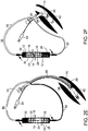
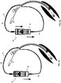
- FIGs. 2A-J illustrate an intubation system 50 which comprises device 10 connected to a tube 60 through fluid delivery line 52 and a suction line 54.
- Tube 60 can be an endotracheal tube, as schematically illustrated in FIGs. 2A-E or a tracheostomy tube as schematically illustrated in FIGs. 2F-J .
- Tube 60 includes cuff 62, fluid suction port 66 and fluid delivery port 68. Ports 66 and 68 are in fluid communication with external suction tube 54 and external delivery tube 52 respectively.
- Device 10 of FIGs. 2A-J comprises syringes 12 which are connected back to back with plungers 18 interconnected via element 23.
- Element 23 in this case is a strut which is compressible to a folded configuration of a predetermined length or stretched to a linear configuration of a predetermined length. This length change in element 23 provides each plunger 18 with a preset range of independent movement.
- FIGs. 2A and 2F illustrate system 50 in the initial state.
- Syringe 32 is filled with about 4 ml of a rinsing solution (saline or/and diluting fluid or/and antiseptic fluid), while syringe 26 is filled with about 12 ml of the same solution. Other amounts are not excluded from the scope of the present invention.
- Element 23 is shown in the compressed state thus allowing independent movement of plungers 24 and 30.
- FIGs. 2B-C and 2G-H illustrate priming of suction line 54 via actuation of plunger 30 (arrow FIGs. 2B and 2G ); excess rinsing solution fills subglottic region 70.
- FIGs. 2C and 2H illustrate priming of rinsing line 52 via actuation of plunger 24; excess rinsing fills subglottic region 70.
- Device 10 can then be disconnected from lines 52 and 54 which are then capped. Device 10 can then be disposed of or sent to laboratory for diagnosis purposes and replaced with a new device 10 if additional irrigation/evacuation is needed.
- Device 10 depicted in FIGs. 2A-J employs a symmetric syringe configuration which, at the concomitant delivery-suction phase, suctions a volume of fluid which is identical to that delivered.
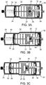
- FIGs. 3A-C employs syringes 12 of different barrel and plunger diameters - syringe 32 has a larger barrel diameter (and hence larger volume per stroke length of plunger 18 ) than that of syringe 26.
- Such an asymmetric syringe configuration enables syringe 32 of device 10 to suction a larger volume of fluid than that delivered by syringe 26 of device 10 during the concomitant delivery-suction phase ( FIG. 3C ). This enables device 10 to more effectively clear fluids from a cavity, especially one which includes excess volume of natural secretions (e.g. subglottic cavity).
- Device 10 of FIGs. 3A-C incorporates an element 23 configuration which enables independent movement of syringe 32 through a locked tongue and groove configuration.
- This configuration of element 23 enables limited movement of tongue 25 in groove 27.
- tongue 25 moves out of groove 27 to a locked position ( FIGs. 3B )
- pushing in plunger 24 of syringe 26 draws out plunger 30 of syringe 32 generating a suction force in syringe 32.
- plunger 30 can be modified to include a spring such that the step of priming, in which plunger 30 is pushed in, loads the spring (e.g. compresses it) and locks element 23 with the spring loaded. Releasing element 23 releases the spring and automatically withdraws plunger 30 thereby automatically pushing in plunger 24.
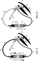
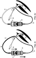
- FIGs. 4A-J illustrate the stages of operation of embodiments of the present device, in which the device comprises a spring that is stretched when a lock is release.
- FIGs. 4A-E illustrate a system in which the device is connected to an endotracheal tube
- FIGs. 4F-J illustrate a system in which the device is connected to an tracheostomy tube.
- the spring facilitates automatic of the suction lines, wherein the operator pushes the lever only in one direction to the end.
- the spring can be unidirectional or bidirectional. In the illustrations of FIGs. 4A-J a unidirectional spring is employed.
- FIGs. 4A and 4F illustrate system 50 in the initial state.
- the syringe is filled with, e.g., 4 ml of rinsing solution while the other syringe is filled with, e.g., 12 ml of the same solution, as further detailed hereinabove.
- FIGs. 4B-C and 4G-H illustrate priming of the suction line ( FIGs. 4B and 4G ), and rinsing line ( FIGs. 4C and 4H ), as further detailed hereinabove.
- FIGs. 4D and 4I illustrate the simultaneous rinsing (via the rinsing line) and suction (via the suction line). Concomitant delivery and suction irrigates the subglottic region and removes any secretions accumulated in this cavity ( FIGs. 4E and 4J ).
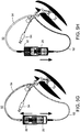
- FIGs. 5A-H illustrate the stages of operation of the device in embodiments in which the device comprises a bidirectional spring that is stretched when a lock is release.
- FIGs. 5A-D illustrate a system in which the device is connected to an endotracheal tube
- FIGs. 5E-H illustrate a system in which the device is connected to an tracheostomy tube.
- FIGs. 5A-B and 5E-F illustrate system 50 in the initial state.
- the syringe is filled with, e.g., 4 ml of rinsing solution while the other syringe is filled with, e.g., 12 ml of the same solution, as further detailed hereinabove. Other amounts are not excluded from the scope of the present invention.
- FIGs. 5C and 5G illustrate a generally simultaneous priming of the suction line and rinsing line by the bidirectional spring and FIGs. 5D and 5H illustrate the simultaneous rinsing (via the rinsing line) and suction (via the suction line).
- the configurations described above utilize two syringe-type piston pumps to enable one step irrigation (fluid delivery and concomitant suction).
- the dual syringe configurations exemplified herein are preferred for their simplicity of design, low cost construction and flexibility and ease of use.
- crank, cam or cog-wheel driven pistons of opposing or parallel direction can be used to provide concomitant delivery and suction as described above.
- FIGs. 6A-G Representative examples of several configurations suitable for some embodiments of the present invention are illustrated in FIGs. 6A-G .
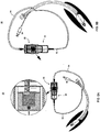
- FIGs. 6A and 6B are schematic illustrations of device 10 in embodiment of the invention in which device 10 comprises a syringe 62 and a container 64, which is optionally and preferably a bag.
- Syringe 62 can primarily serve for withdrawing fluid from the body cavity and container 64 can serve for delivering fluid into the body cavity.
- container 64 is preferably filled with fluid.
- Container 64 is preferably a deformable bag, e.g ., a disposable bag, which can be made of any material such as polyester, polyethylene terephthalate (PET), copolyethylene terephthalate (CoPET), polybutylene terephthalate (PBT) and the like.
- FIGs. 6A and 6B will now be described with reference to FIGs. 6E and 6F .
- FIG. 6E is a cut view of the embodiment shown in FIG. 6A .
- Bag 64 is external to syringe 62 but is encapsulated with it in housing 22, within a compartment having a movable oblique element 65.
- the plunger 63 of syringe 62 comprises or is connected to an extension 67 which engages element 65.
- extension 67 slides on oblique element 65 forcing it to apply pressure on bag 64, thereby delivering the fluid out of bag 64, simultaneously with the withdrawal of fluid by syringe 62.
- FIG. 6F is a cut view of the embodiment shown in FIG. 6B .
- Bag 64 is disposed within the barrel 71 of syringe 62, while the plunger 63 is in its pushed position. Bag 64 is disposed such that the tip 69 of plunger 63 is between bag 64 and the nozzle 73 of barrel 71.
- syringe 62 withdraws fluid out of the body cavity through nozzle 73 while squiring bag 64, thereby delivering the fluid out of bag 64, through a second nozzle 75 which may be disposed laterally to nozzle 73, or, is illustrated in FIG. 6F , circumferential with respect to nozzle 73.
- FIG. 6C is a schematic illustration of device 10 in embodiment of the invention in which device 10 comprises two syringes 62 and 66, wherein syringe 66 is a conventional syringe and syringe 62 is a specially designed syringe.
- syringe 66 is a conventional syringe
- syringe 62 is a specially designed syringe.
- FIG. 6G is a cut view of the embodiment shown in FIG. 6C .
- Syringe 62 is filled with fluid (not shown in FIG. 6G ).
- the plunger 63 of syringe, 62 is mounted, or being formed, with an extension element 77 than engages the plunger 79 of syringe 66.
- syringe 66 withdraws fluid out of the body cavity while at the same time element 77 causes plunger 63 to move at the ejecting direction of syringe 62, thereby delivering the fluid out of syringe 62.
- FIG. 6D is a schematic illustration of a peristaltic pump 68 which can be used for one or both pumps of device 10.
- Peristaltic pumps which are known per se, pump the fluid in a wave-like pattern by sequential deformation and occlusion of several points along the length of a resilient deformable tube 70 which carries the fluid. Operation of such a pump typically involves a mechanical interaction between a portion of resilient tube 70 and a peristaltic mechanism 72 that creates a wave-like deformation along the resilient tube.
- peristaltic pump 68 is manually operated.
- the device comprises a syringe and a vacuum tube.
- FIGs. 7A-E are schematic illustrations of device 10 in embodiments of the invention in which device 10 comprises an actuator member 74, and two piston pumps (shown as syringes 32 and 26 ) which are arranged within housing 22.
- Actuator member 74 is preferably a mechanical member, and can be in the form of, for example, a safety hatch or the like. In various exemplary embodiments of the invention member 74 is being operated manually without the use of any other drive means such as an electrical or magnetic motor or an acoustical transducer.
- Pump 26 and pump 32 are optionally and preferably initially filled with respective initial volumes 76 and 78 of fluid, e.g., irrigation liquid.
- initial volumes 76 and 78 of fluid e.g., irrigation liquid.
- volume 76 is 5 cc
- volume 78 is 10 cc, but other amounts are not excluded from the scope of the present invention.
- Member 74 has a first mode ( FIG. 7A ) in which both pumps are inoperative. In this mode member 74 serves as a safety hatch, and device 10 can be shifted from one location to the other without the risk of accidental operation. In the representative example of FIG. 7A , which is not considered to be limiting, in the first mode, member 74 assumes an orientation which is perpendicular to symmetry axis of the piston pumps. Member 74 also has a second mode in which actuator member activates pump 32 to eject an initial volume 76 of fluid out of the device. In this mode, volume 78 of pump 26 is still filled with fluid.
- Switching from the first mode to the second mode can be, for example, by rotating member 74 by 90° to assume an orientation which is generally parallel to the symmetry axis of the piston pumps ( FIG. 7B ).
- the rotation generates a force applied by the tip of member 74 on the piston of pump 32, which ejects the fluid in volume 76.
- member 74 also has a third mode, in which member 74 activates pump 26 to eject an initial portion of the fluid in volume 78 out of the device. Typically, about 2cc are ejected in the third mode of member 74. Other amounts are not excluded from the scope of the present invention Switching from the second mode to the third mode can be, for example, by pulling member 74 outwardly (see arrow 80 ) .
- a linkage member 82 which is connected to actuator member 74 extends from member 74 to the piston of pump 26.
- An engaging element 84 at the part of member 82 which is close to pump 26 engages the piston and pushes it in the ejection direction of pump 26, thereby ejecting part of the fluid in volume 78 ( FIG. 7C ).
- member 74 also has a fourth mode, in which member 74 simultaneously activates pump 26 to deliver fluid into the body cavity and pump 32 to withdraw fluid from the body cavity.
- member 74 simultaneously activates pump 26 to deliver fluid into the body cavity and pump 32 to withdraw fluid from the body cavity.
- all the remaining fluid in volume 78 are ejected in the third mode of member 74.
- Switching from the third mode to the fourth mode can be, for example, by pulling member 74 further outwardly ( FIG. 7D ).
- Engaging element 84 continues to push the piston of pump 26 in its ejecting direction (direction 80 in the present example) while a lever mechanism 86 pulls the piston of pump 32 in its withdrawing direction (in the present example, also direction 80 ) .
- fluids enter pump 26 and exit pump 26.
- member 74 also has a fifth mode, in which member 74 activates only pump 32 to withdraw fluid from the body cavity. Switching from the fourth mode to the fifth mode can be, for example, by pulling member 74 further outwardly ( FIG. 7E ), to effect a motion of the piston of pump 32 (via lever mechanism 86 ) withdrawing direction 80 thereby facilitating withdrawal of fluids into the device. Since pump 26 does not contain any fluid once member 74 enters its fourth mode, the further pulling of member 74 after the fourth mode does not affect pump 26.
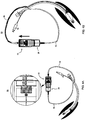
- FIGs. 8A and 8B are schematic illustration of system 50 in embodiments of the present invention in which device 10 including member 74 is connected to tube 60.
- FIG. 8A show system 50 in embodiments in which tube 60 is adapted for being introduced into the trachea (either orally or in a tracheostomy procedure), and
- FIG. 8B shows system 50 in embodiments in which tube 60 is adapted for being inserted into the ear canal.
- the skilled person provided by the details provided herein, will know how to adjust the drawings for embodiments in which tube 60 is introduced into other cavities, e.g., the intestines.
- FIGs. 9A and 9B are schematic illustrations of device 10 in embodiments of the invention in which device 10 comprises an analog ( FIG. 9A ) or digital ( FIG. 9B ) pressure measuring device 90.
- Device 90 can be mounted, for example, onto housing 22 of device 10.
- Device 90 comprises an inlet 92 which can be connected, for example, to the cuff inflation line of tube 60 (not shown, see 94 in FIGs. 2A-J , 4A-J , 5A-H and 8A ), for determining the inflation pressure of the cuff.
- This embodiment is particularly useful when the intubated subject is connected to a ventilation or anesthetic machine which does not provide indication of cuff inflation pressure.
- Measuring device can be of any type known in the art, including, without limitation, a device incorporating a pressure sensor, e.g., a piezoelectric or a piezoresistive element, a manometer, e.g ., a capacitance manometer, a mercury manometer, a flow meter, and the like.
- a pressure sensor e.g., a piezoelectric or a piezoresistive element
- a manometer e.g a capacitance manometer, a mercury manometer, a flow meter, and the like.
- the device of the present embodiments may, if desired, be presented in a pack, such as an FDA-approved kit.
- the pack may, for example, comprise metal or plastic foil, such as a blister pack.
- the pack may be a disposable pack.
- the pack may be accompanied by instructions for administration.
- the pack may also be accompanied by a notice in a form prescribed by a governmental agency regulating the manufacture, use, or sale of pharmaceuticals, which notice is reflective of approval by the agency of the form of the compositions for human or veterinary administration.
- Such notice for example, may include labeling approved by the U.S. Food and Drug Administration for prescription drugs or of an approved product insert.
- FIG. 10 A representative example of a pack according to some embodiments of the present invention is illustrated in FIG. 10 .
- the device shown in FIG. 7A-F can be installed within an automatic syringe pump that replaces the manual activation by configured external electric piston that pulls the safety hatch and draws the evacuation plunger in a programmed mode.
- the automatic device can include one or more devices connected to same lumens.
- the device of the present embodiments optionally and preferably includes therein one or more types of substances that are capable of providing indication of presence of a disease.
- the substance or substances are incorporated in the pump that serves for withdrawing fluid from the body cavity.
- the substance can change its property, for example, optical property (e.g ., color) when contacted with diseased secretions.
- the substance can comprise for example, a functional group that react with the disease of interest and provides indication of its existence.
- the substance can also be a biological marker, such as, but not limited to, cells, proteins, enzymes, nucleic acids, carbohydrate markers, cell surface markers, circulating antibodies, secretory antibodies, cell-associated antibodies, intracellular markers, morphological markers, functional parameters (e.g. enzymatic activity), pH, cytokines and chemokines, viral markers, bacteria, fungi, protozoa, nematodes and parasites.
- a method suitable for irrigating a body cavity with fluid comprises manually delivering a first volume of fluid to the body cavity, and manually delivering a second volume of the fluid and simultaneously withdrawing at least second volume of the fluid from the body cavity.
- the method can be effected, for example, by a device that includes manually-operated pump mechanism as further detailed hereinabove, e.g., device 10.
- the method delivers fluid is at volumetric flow rate Q 1 , and simultaneously withdraws fluid at volumetric flow rate Q 2 , wherein there is a linear relation between Q 1 and Q 2 , as further detailed hereinabove.
- the method is optionally and preferably executed using a device which is connected to the body cavity via a tube having a first line in fluid communication with the first pump of the device and a separate second line in fluid communication with the second pump of the device.
- the following protocol is preferably, but not necessarily employed.
- the second pump is operated to deliver fluid into the second line, so as to at least fill second line.
- the first pump is operated to deliver fluid into the first line, so as to at least fill first line. Once the lines are filled, the first pump is operated to withdraw fluid from the first line and the second pump is simultaneously operated to deliver fluid into the second line. Subsequently, the first pump is operated to withdraw fluid from the first line while the second pump remains inoperative.
- compositions, method or structure may include additional ingredients, steps and/or parts, but only if the additional ingredients, steps and/or parts do not materially alter the basic and novel characteristics of the embodimented composition, method or structure.
- a compound or “at least one compound” may include a plurality of compounds, including mixtures thereof.
- range format is merely for convenience and brevity and should not be construed as an inflexible limitation on the scope of the invention. Accordingly, the description of a range should be considered to have specifically disclosed all the possible subranges as well as individual numerical values within that range. For example, description of a range such as from 1 to 6 should be considered to have specifically disclosed subranges such as from 1 to 3, from 1 to 4, from 1 to 5, from 2 to 4, from 2 to 6, from 3 to 6 etc., as well as individual numbers within that range, for example, 1, 2, 3, 4, 5, and 6. This applies regardless of the breadth of the range.
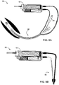
- a prototype MASS device and an FDA/CE approved endotracheal tube were manufactured and tested according to some embodiments of the present invention.
- the prototype MASS device and the endotracheal tube are illustrated in FIGs. 11A-B .
- the prototype MASS device included two opposingly mounted syringes with their plungers linked such that they can operate simultaneously, as described in greater detail above.
- the endotracheal tube included a main lumen, two suction lumens embedded in the wall of the main lumen at the dorsal side of the tube with distal openings above the cuff, and an irrigation lumen embedded in the wall of the main lumen at the ventral side of the tube and having an opening above the cuff.
- the embedded suction lumens were unified to one external lumen.
- a cross section of the tube is illustrated in FIG. 11B .
- a goat was anesthetized (Ketamine and Isofluran) and intubated with the endotracheal tube. Sealing was validated by above cuff CO 2 reading, as disclosed, for example, in Efrati, MD et al., "Optimization of Endotracheal Tube Cuff Filling by Continuous Upper Airway Carbon Dioxide Monitoring," Anesth. Analg; vol. 101, pp. 1081-1088 (2005 ). CO 2 was monitored through the vent lumen of the tube. A partial CO 2 pressure of less than 1 mmHg, was considered as indicative of adequate sealing.
- Contrast medium (OMNIPAQUE- IOHEXOL 350 mgl/ml) was used for simulation of above cuff fluid. 5cc of contrast medium were injected via the suction lumen under fluoroscopy recording.
- the prototype MASS device was used for synchronized irrigation and suction. 10cc of Saline were used for irrigation. The entire irrigation/suction procedure was monitored and recorded by fluoroscopy. The amount of the evacuated fluids were measured and recorded.
- the goat was intubation with a Hi-Lo Evac endotracheal tube (I.D 8.0 Polyurethane cuff; Evac, Mallinckrodt, USA).
- the cuff pressure was set to 20 mmHg and sealing was validated by above cuff CO 2 reading as further detailed hereinabove. The CO 2 readings were done through the suction lumen.
- Contrast medium OMSNIPAQUE- IOHEXOL 350 mgI/ml
- 5cc of contrast medium were injected via the suction lumen under fluoroscopy recording.
- 10cc of saline were injected via the suction lumen.
- Secretions were evacuated with a 20 cc Syringe. The entire irrigation/suction procedure was monitored and recorded by fluoroscopy. The amount of the evacuated fluids were measured and recorded. The experiment was repeated with the following cuff pressure 20, 15, 10 and 5 mmHg.
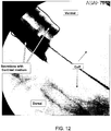
- FIG. 12 is a fluoroscopy image of the goat's trachea with the endotracheal tube of the present embodiments before the evacuation of the secretions.
- the secretions (dark regions) and cuff (central region) are bordered on the image.
- FIG. 13 is a fluoroscopy image of the goat's trachea with the endotracheal tube after the evacuation of the secretions using the prototype MASS device of the present embodiments. As shown, the secretions have been removed by their entirety.
- Table 1 and FIGs. 12 and 13 demonstrate that after the MASS procedure (Experiment 1) no leakage around the cuff was detected by fluoroscopy and the whole amount of fluids that were rinsed and the amount of contrast medium were aspirated.
- the prototype MASS device of the present embodiments with its related synchronized rinsing/suction procedure assured a comprehensive evacuation of secretions from above the cuff.
- Table 2 demonstrates that employing rinsing followed by suction in the endotracheal tube resulted in complete evacuation of secretions above the cuff.
- FIG. 14 is a fluoroscopy image of the goat's trachea with the Hi-Lo® Evac tube before the evacuation of the secretions.
- the secretions (dark regions) and cuff (central region) are bordered on the image.
- FIG. 15 is a fluoroscopy image of the goat's trachea with the Hi-Lo® Evac tube after the evacuation of the secretions by rinsing followed by suction.
- the secretions (dark regions) and cuff (central region) are bordered on the image.
- Table 3 and FIGs. 14 and 15 demonstrate that employing rinsing followed by suction in the Hi-Lo® Evac tube resulted in only partial evacuation of secretions leaving diluted secretions above the cuff at the end of the procedure.
Landscapes
- Health & Medical Sciences (AREA)
- Heart & Thoracic Surgery (AREA)
- Life Sciences & Earth Sciences (AREA)
- Veterinary Medicine (AREA)
- Anesthesiology (AREA)
- Biomedical Technology (AREA)
- Engineering & Computer Science (AREA)
- Hematology (AREA)
- Public Health (AREA)
- Animal Behavior & Ethology (AREA)
- General Health & Medical Sciences (AREA)
- Pulmonology (AREA)
- Emergency Medicine (AREA)
- Vascular Medicine (AREA)
- Physics & Mathematics (AREA)
- Fluid Mechanics (AREA)
- Infusion, Injection, And Reservoir Apparatuses (AREA)
- External Artificial Organs (AREA)
Description
- This application claims the benefit of priority from U.S. Application Nos.
61/359,404, filed on June 29, 2010 61/406,201, filed on October 25,2010 - The present invention, in some embodiments thereof, relates to a hand-held, and optionally manually-operated, device for irrigating-evacuating a body cavity and specifically, but not exclusively, to a manually operated pumps mechanism which can be used to remove secretions from a subglottic region of an intubated subject.
- Intubation involves positioning of a tube, such as an endotracheal tube (ETT) or a tracheostomy tube through the trachea of a subject terminating at a position above the carina, anterior to a position between the second and fourth thoracic vertebrate.
- Endotracheal intubation is used to mechanically ventilate the subject's lungs when normal breathing is not supported, or to apply anesthetic gases during surgical intervention.
- Tracheostomy is an operative procedure that creates a surgical airway in, anterior to a position between the cervical trachea. The resulting stoma can serve independently as an airway or as a site for a tracheostomy tube to be inserted. This tube allows a person to breathe without the use of their nose or mouth, or being mechanically ventilated when hospitalized or in homecare environment
- In order to create enough air pressure to accomplish mechanical ventilation and to prevent escape of gases past the tube, the tubes are sealed against the trachea using, for example, an inflatable cuff.
- The inflatable cuff is inflated so as to engage the wall of the trachea and thereby seal the trachea and prevent gases being introduced through the tracheal tube from simply leaking around the tube. While use of an inflatable cuff is important for operability of an ETT, it can also contribute to complications.
- Intubated patients can develop pneumonia resulting from an infection of the lungs induced by contaminated, pooled secretions with digestive content bypassing the epiglottis. To overcome these risks, endotracheal and tracheostomy tubes which enable single lumen suction or double lumen irrigation and suction of such secretions have been developed. Single lumen suction tubes are limited in that the suction often causes direct suction to be exerted on the tracheal mucosa which may then result in damage to the mucosa. Double lumen tubes while being vastly superior in enabling clearance of secretions require the use of complicated and expensive irrigation pumps.
-
U.S. Published Application No. 2003/069549 teaches two pistons that are operated simultaneously in opposite directions. One disclosed device ejects and withdraw simultaneously, and the other disclosed device ejects simultaneously from two chambers or withdraw simultaneously into the two chambers. -
U.S. Patent No. 4,909,783 discloses an apparatus for maintaining pressure in a body cavity while simultaneously removing and replacing fluid therein. The apparatus includes two syringes, one for discharging a fluid and the other for drawing in a fluid, and means for equally and oppositely displacing the plungers in the barrels. The barrels and plungers are mounted parallel to one another along the same axis, and that relative movement between attached plungers and attached barrels effects equal and opposite operation of the syringes, and simultaneous infusion and aspiration at precisely equal volumes. -
U.S. Patent No. 4,457,747 discloses two coupled syringes, one for use in a blood withdrawal system and one for use in a fresh blood injection system. The volume of blood removed from a baby in the withdrawal system is simultaneously replaced by an equal volume of fresh blood from the injection system. - International Publication No.
WO 1992007602 discloses an endotracheal tube having means to evacuate contaminated secretions which includes a double lumen through which air is circulated. -
U.S. Patent No. 5,957,883 discloses a synchronous vitreous lavage device for ophthalmology. The lavage device simultaneously drains bloody water from the eyeball, and injects lavage water into the eyeball by means of two syringes. - The present invention provides a device for irrigating a body cavity according to claim 1, and an intubation system according to
claim 14. - According to an aspect of some embodiments of the present invention there is provided a device for irrigating a body cavity with fluid. In various exemplary embodiments of the invention the device is a hand-held device. The device comprises a pump mechanism configured for delivering a first volume of fluid to the body cavity and delivering a second volume of fluid to the body cavity while concomitantly withdrawing at least the second volume of fluid from the body cavity. The pump mechanism is optionally and preferably a manually-operated pump mechanism.
- According to some embodiments of the invention the pump mechanism is configured to deliver fluid to the body cavity at a first volumetric flow rate and simultaneously withdraw fluid from the body cavity at a second volumetric flow rate, and wherein there is a linear relation between the first and the second volumetric flow rates.
- According to some embodiments of the invention the mechanism comprises a first pump and a second pump each being configured for communicating fluid to and from the body cavity, the first pump and the second pump being operatively linked such that operating the second pump to deliver the second volume of fluid into the body cavity activates the first pump to withdraw the at least the second volume of fluid from the body cavity.
- According to some embodiments of the invention the mechanism comprises a first pump and a second pump each being configured for communicating fluid to and from the body cavity, the first pump and the second pump being operatively linked such that operating the first pump to withdraw the at least the second volume of fluid from the body cavity activates the second pump to deliver the second volume of fluid into the body cavity.
- According to some embodiments of the invention the first and the second pumps are, respectively, a first and a second piston pumps and wherein the first piston of the first pump is operatively linked to a second piston of the second pump.
- According to some embodiments of the invention the first piston and the second piston are linked in a manner which enables independent movement of the first piston and the second piston through a preset movement range and linked movement of the first piston and the second piston beyond the preset movement range.
- According to some embodiments of the invention movement of the first piston within the preset movement range delivers the first volume of fluid to the body cavity and further wherein movement of the second piston beyond the preset movement range delivers the second volume of fluid and operates the first piston to withdraw the at least the second volume of fluid.
- According to some embodiments of the invention the piston pumps are syringes having manually operateable plungers.
- According to some embodiments of the invention the piston pumps are aligned parallel to each other such that a withdrawing direction of the first piston pump is opposite to an ejecting direction of the second piston pump.
- According to some embodiments of the invention the piston pumps are aligned parallel to each other such that a withdrawing direction of the first piston pump is parallel to an ejecting direction of the second piston pump.
- According to some embodiments of the invention the device comprises an actuator member having a first mode in which both the pumps are inoperative, and a second mode in which the actuator member activates the first pump to eject an initial volume of fluid out of the device.
- According to some embodiments of the invention the actuator member additionally has a third mode in which the actuator member activates the second pump to eject a further initial volume of fluid out of the device.
- According to some embodiments of the invention the actuator member additionally has a fourth mode in which the actuator member simultaneously activates the second pump to deliver fluid into the body cavity and the first fluid pump to withdraw fluid from the body cavity.
- According to some embodiments of the invention the actuator member additionally has a fifth mode in which the actuator member activates only the first fluid pump to withdraw fluid from the body cavity.
- According to some embodiments of the invention the actuator member is a mechanical member.
- According to some embodiments of the invention at least one of the first and the second pumps is a peristaltic pump.
- According to some embodiments of the invention the first pump is a container having an under pressure therein.
- According to some embodiments of the invention the second pump is a deformable bag.
- According to some embodiments of the invention the device comprises a pressure measuring device.
- According to some embodiments of the invention the pump mechanism comprises a biomarker therein.
- According to an aspect of some embodiments of the present invention there is provided an intubation system comprising the device according to any of embodiments 1-20, and a tube assembly adapted for being introduced into the body cavity.
- According to an aspect of some embodiments of the present invention there is provided a method of irrigating a body cavity with fluid. The method comprises: (a) delivering a first volume of fluid to the body cavity; and (b) delivering a second volume of the fluid and simultaneously withdrawing at least the second volume of the fluid from the body cavity. In various exemplary embodiments of the invention the first and second volumes are delivered manually.
- According to some embodiments of the invention the method is effected by a device which comprises a first pump and a second pump each being configured for communicating fluid to and from the body cavity, the first pump and the second pump being operatively linked such that operating the second pump to deliver the second volume of fluid into the body cavity activates the first pump to withdraw the at least the second volume of fluid from the body cavity.
- According to some embodiments of the invention the method is effected by a device which comprises a first pump and a second pump each being configured for communicating fluid to and from the body cavity, the first pump and the second pump being operatively linked such that operating the first pump to withdraw the at least the second volume of fluid from the body cavity activates the second pump to deliver the second volume of fluid into the body cavity
- According to some embodiments of the invention (a) is effected by operating the second pump to deliver a first volume of fluid to the body cavity.
- According to some embodiments of the invention (b) is effected by manually operating the first pump to deliver a second volume of the fluid to the body cavity thereby operating the second pump to withdraw fluid from the body cavity.
- According to some embodiments of the invention the device is connected to the body cavity via a tube having a first line in fluid communication with the first pump and a separate second line in fluid communication with the second pump, and the method comprises: operating the second pump to deliver fluid into the second line, so as to at least fill the second line; operating the first pump to deliver fluid into the first line, so as to at least fill the first line; and simultaneously operating the first pump to withdraw fluid from the first line and the second pump to deliver fluid into the second line.
- According to some embodiments of the invention the manually delivering the second volume of the fluid is at a first volumetric flow rate, and the simultaneously withdrawing the at least the second volume of the fluid is at a second volumetric flow rate, and wherein there is a linear relation between the first and the second volumetric flow rates.
- According to some embodiments of the invention the method comprises subsequently to the (b), withdrawing fluid from the body cavity without delivering fluid into the body cavity.
- According to some embodiments of the invention the body cavity is the trachea. According to some embodiments of the invention the method is executed during tracheotomy intubation. According to some embodiments of the invention the method is executed during oral endotracheal intubation. According to some embodiments of the invention the method comprises connecting the irrigation device to an intubation device which comprises: a flexible tubular body being adapted for being introduced into the trachea of a subject and defining a main lumen; and an inflatable cuff associated with the tubular body and arranged to be located at a location in the patient trachea; the wall being embedded with at least: (i) two suction lumens with respective openings above the cuff, the openings being arranged laterally with respect to each other within the wall, (ii) a cuff inflation lumen with opening at the cuff, and (ii) an irrigation lumen with opening above the cuff.
- According to some embodiments of the invention the body cavity is the ear canal.
- According to some embodiments of the invention the body cavity is the intestines.
- According to an aspect of some embodiments of the present invention there is provided a device for irrigating a body cavity with fluid. The device comprises two manually-operated syringes having linked plungers, wherein pushing in a first plunger of a first syringe beyond a predetermined travel distance withdraws a second plunger of a second syringe.
- According to some embodiments of the invention the two manually-operated syringes are of different volumes and/or plunger stroke length.
- According to an aspect of some embodiments of the present invention there is provided a kit. The kit comprises the irrigation device as described herein and an intubation device, wherein the intubation device comprises: a flexible tubular body being adapted for being introduced into the trachea of a subject and defining a main lumen; and an inflatable cuff associated with the tubular body and arranged to be located at a location in the patient trachea; the wall being embedded with at least: (i) two suction lumens with respective openings above the cuff, the openings being arranged laterally with respect to each other within the wall, (ii) a cuff inflation lumen with opening at the cuff, and (ii) an irrigation lumen with opening above the cuff.
- According to some embodiments of the invention the wall has a dorsal section and a ventral section at opposite sides of a longitudinal axis of the tubular body, and wherein the openings of the suction lumens are both located at the dorsal section. Preferably, the openings of the suction lumens are separated by a an azimuthal angle which is less than a with respect to the center of a cross-section perpendicular to the longitudinal axis, where α is less than 100° or less than 90° or less than 80° or less than 70° or less than 60° or less than 50° or less than 40° or less than 30° or less than 20°. According to some embodiments of the invention the opening of the irrigation lumen is located at the ventral section. According to some embodiments of the invention the opening of the evacuation lumens are located at the dorsal section having openings with ducts on the sidereal to enlarge suction ports.
- According to some embodiments of the invention the suction lumens are unified to a single conduit external to the tubular body.
- According to some embodiments of the invention the tubular body is adapted for oral endotracheal intubation. According to some embodiments of the invention the tubular body is adapted for tracheostomy intubation.
- Unless otherwise defined, all technical and/or scientific terms used herein have the same meaning as commonly understood by one of ordinary skill in the art to which the invention pertains. Although methods and materials similar or equivalent to those described herein can be used in the practice or testing of embodiments of the invention, exemplary methods and/or materials are described below. In case of conflict, the patent specification, including definitions, will control. In addition, the materials, methods, and examples are illustrative only and are not intended to be necessarily limiting.
- Some embodiments of the invention are herein described, by way of example only, with reference to the accompanying drawings and images. With specific reference now to the drawings in detail, it is stressed that the particulars shown are by way of example and for purposes of illustrative discussion of embodiments of the invention. In this regard, the description taken with the drawings makes apparent to those skilled in the art how embodiments of the invention may be practiced.
- In the drawings:
-
FIGs. 1A-D are schematic illustrations of the stages of operation of a device, according to some embodiments of the present invention. -
FIGs. 2A-E are schematic illustrations of the stages of operation a device in embodiments in which the device is connected to an endotracheal tube. -
FIGs. 2F-J are schematic illustrations of the stages of operation a device in embodiments in which the device is connected to a tracheostomy tube. -
FIGs. 3A-C are schematic illustrations of the stages of operation of a device, specifically showing different barrel and plunger diameters, according to some embodiments of the present invention. -
FIGs. 4A-E are schematic illustrations of the stages of operation of the device in embodiments in which the present device is attached to an endotracheal tube and a unidirectional spring is employed. -
FIGs. 4F-J are schematic illustrations of the stages of operation of the device in embodiments in which the present device is attached to a tracheostomy tube and a unidirectional spring is employed. -
FIGs. 5A-D are schematic illustrations of the stages of operation of an embodiment in which the present device is attached to an endotracheal tube and a bidirectional spring is employed. -
FIGs. 5E-H are schematic illustrations of the stages of operation of an embodiment in which the present device is attached to a tracheostomy tube and a bidirectional spring is employed. -
FIGs. 6A-G are schematic illustrations of pump mechanisms, according to some embodiments of the present invention. -
FIGs. 7A-E are schematic illustrations of a device in embodiments of the invention in which the device comprises an actuator member. -
FIGs. 8A and 8B are schematic illustration of a system which comprises a device that including an actuator member and a tube. -
FIGs. 9A and 9B are schematic illustrations of a device in embodiments of the invention in which the device comprises a pressure measuring device. -
FIG. 10 is a schematic illustration of a pack including two devices, according to some embodiments of the present invention. -
FIGs. 11A-B are schematic illustrations and an image of a device and an endotracheal tube, used in experiments performed according to some embodiments of the present invention. -
FIG. 12 is a fluoroscopy image of a goat's trachea with the endotracheal tube of the present embodiments before evacuation of the secretions. -
FIG. 13 is a fluoroscopy image of the goat's trachea with the endotracheal tube after the evacuation of the secretions using the prototype device of the present embodiments. -
FIG. 14 is a fluoroscopy image of the goat's trachea with a conventional tube before a evacuation of the secretions. -
FIG. 15 is a fluoroscopy image of the goat's trachea with the conventional tube after the evacuation of the secretions by rinsing followed by suction. - The present invention, in some embodiments thereof, relates to a hand-held, and optionally a manually-operated, device for irrigating-evacuating a body cavity and specifically, but not exclusively, to a manually operated pump mechanism which can be used to remove secretions from a subglottic region of an intubated subject.
- Before explaining at least one embodiment of the invention in detail, it is to be understood that the invention is not necessarily limited in its application to the details of construction and the arrangement of the components and/or methods set forth in the following description and/or illustrated in the drawings and/or the Examples. The invention is capable of other embodiments or of being practiced or carried out in various ways.
- The present inventors have previously described endotracheal tubes which are designed for facilitating removal of secretions from a subglottic region using automated pump mechanisms (see
WO2007/066332 ). Although such endotracheal tube configurations are highly effective in reducing complications associated with migration of secretions into the lungs, the requirement for sophisticated pump mechanisms for operability can be limiting - In efforts of overcoming these requirements, the present inventors devised a manually-operated pump mechanism which is characterized by at least one of:
- (i) a simple design - reduces costs of manufacturing and use;
- (ii) simple and easy operation - simple to setup and operate, designed to provide operability familiar to medical personnel;
- (iii) single use - reduces risk of contaminations and traverses need for sterilization; and
- (iv) provides a clear indication of irrigation and of secretions/debris evacuated from an irrigated body cavity.
- (v) reducing time and providing more frequent diagnosis by sending the device with evacuated to secretions to laboratory before disposing it.
- Thus, according an aspect of some embodiments of the present invention there is provided a device for irrigating and evacuating a body cavity.
- As used herein, the term "irrigating" refers to running fluid into and out of the body cavity for the purpose of evacuating secretions, debris and the like.
- As used herein, "a body cavity" refers to naturally occurring or artificially formed cavities within tissue structures. One example of a cavity is the space formed below the glottis and above an inflatable cuff of an endotracheal tube or a tracheostomy tube. Other examples including, without limitation, the ear canal, and the intestines.
- In embodiments of the invention in which the device is adapted for manually irrigating and evacuating the space defined between the tracheal wall and an endotracheal tube or a tracheostomy tube below the glottis and above the inflatable cuff, the device is termed Manual Aspiration of Subglottic Secretions (MASS) device.
- The device of the present embodiments includes a manually-operated pump mechanism capable of delivering a volume of fluid to the body cavity while concomitantly withdrawing a volume of fluid from the body cavity (through suction). Such delivery is typically effected through two fluid lines (delivery and suction) each separately connected to the pump mechanism of the present embodiments at one end, while the opposite end of each fluid line is disposed within the body cavity or connected to a device being in fluid communication with the body cavity (e.g. an endotracheal tube such as that shown in
FIGs. 2A-E orFIG. 4A-E or5A-D or that described inWO2007/066332 , or a tracheostomy tube such as that shown inFIGs. 2F-J orFIG. 4F-4J or5E-5H ). - Manually operated pump mechanisms such as syringes are relatively inexpensive to fabricate and easy to operate. However, such mechanisms are typically limited in that each stage of an irrigation procedure (pumping fluid in and pumping fluid out) requires a separate manual operation of the pump piston (syringe plunger). Although mechanical pumps capable of continuous operation (e.g. peristaltic) can be manually operated to circulate a fluid through a cavity they can be difficult to operate and are less suitable for use in medical applications which require periodic rapid irrigation with low volumes of fluid under sterile conditions.
- The manually operated pump mechanism of the present embodiments is configured for delivering a volume of fluid into the cavity while simultaneously or sequentially (or semi-sequentially) withdrawing that volume in a single stage of operation thus enabling rapid and easy irrigation of the body cavity and traversing the limitations of prior art devices such as simple syringes.
- During the operation phase in which the pump mechanism delivers fluid to the body cavity and simultaneously withdraw fluid from the body cavity, there is always a linear relation between the volumetric flow rate Q1 at which the fluid is delivered and the volumetric flow rate Q2 at which fluid is withdrawn. For example, Q2=Q1, or Q2=aQ1 or Q2=aQ1+b, where a and b are constants. In some embodiments of the present invention b=0.
- The manually operated pump mechanism of the present embodiments is optionally and preferably also configured to enable a priming operation in which a first volume of fluid is first delivered into the cavity without simultaneous withdrawal of that fluid. Such a priming stage fills the suction line and optionally partially fills the body cavity so as to establish a fluid continuum between the pump mechanism and the body cavity and prevent compressible gas voids within suction line.
- This feature is particularly important since air filled suction lines can collapse due to tissue occlusion of suction ports. Under suction pressure, tissue sucked into a suction port can cause a suction line to collapse. If the suction line is filled with a fluid such as saline (which unlike air is not compressible) a continuum is created between the pump mechanism and the fluid in the body cavity thereby preventing collapse of the suction line and occlusion of the suction line.
- To enable such 'priming' of fluid lines and especially the fluid suction line, the mechanism of the present embodiments enables a two stage operation in which in a first stage (priming) a first volume of fluid is delivered to the body cavity via the irrigation mechanism (without simultaneous fluid withdrawal), followed by a second stage of operation (irrigation using a second fluid line that delivers fluid into the cavity) in which delivery and simultaneous withdrawal of a second (and typically larger) volume of fluid is effected. Preferably, the second (delivery) line is also primed with fluid prior to delivery and simultaneous withdrawal.
- Several configurations of the device of the present embodiments can be used to enable such functionality, one preferred configuration of the present device includes a pump mechanism constructed from two operably linked piston pumps having opposingly operable pistons actuatable via a single manual operation.
- Such linked operation can be used to deliver fluid into the body cavity from a first piston pump while simultaneously withdrawing fluid from the body cavity through the second and operatively linked piston pump.
- Several piston pump configurations can be used to provide such operability. One configuration which is particularly useful for medical applications is a dual syringe configuration having operatively linked plungers.
- A device configuration using two interconnected syringes is easy and inexpensive to manufacture, can be disposed of with ease following a single use (thereby lending itself to medical applications) and provides the treating physician with familiar operability.
-
FIGs. 1A-D illustrate one embodiment of a dual syringe device which is referred to herein asdevice 10. -
Device 10 includes twopumps 12, for example, piston pumps, shown inFIGs. 1A-D as syringes. Each syringe is constructed from a barrel (with nozzle 14 - shown on one syringe) housing aplunger 18 having a seal (not shown) and back stop 34.Syringes 12 are fabricated using materials and methods well known in the art. - One or both
plungers 18 can include a spring element for facilitating plunger withdrawal from the barrel onceplunger 18 is pushed in. Sprung plungers enable a greater degree of control over plunger activation and as such can be advantageous in cases where fluid delivery has to be carefully controlled. Spring loaded plunger configurations are well known to the ordinary skilled artisan. -
Syringes 12 can be connected using removable or non-removable attachment mechanisms.FIGs. 1A-D illustrate configuration ofdevice 10 in whichsyringes 12 are attached to ahousing 22.Housing 22 can be fabricated to accommodate syringes of variable sizes, volumes and plunger stroke lengths. The configuration shown inFIGs. 1A-D includessyringes 12 of non identical volumes (asymmetric configuration), although symmetric configurations in whichsyringes device 10. In asymmetric configurations, asyringe 12 used for suction (32) can be configured to generate a suction volume perplunger 18 stroke (see the configuration ofFIGs. 3A-C which is further described hereinunder) which is greater than the delivery volume ofsyringe 26. This enables suctioning of the irrigation fluid delivered fromsyringe 26 as well as any fluid contained in the cavity (e.g. secretions etc). - The volume of each syringe, as well as
plunger 18 stroke length are selected according to the irrigation procedure, for example, in the case of subglottic irrigation, each syringe can contain about 2-10 ml deliverable through a plunger stroke length of about 5-10 cm. Other amounts are not excluded from the scope of the present invention.FIGs. 1A-D illustratesyringes 12 in an 'over and under' configuration however, other arrangements such as that of the configuration shown inFIGs. 2A-8B are also envisaged. - As is mentioned hereinabove,
device 10 of the present embodiments is configured so as to provide fluid delivery and withdrawal via a single manual operation. To enable such functionality,plungers 18 ofsyringes 12 are operatively linked viaelement 23 to move in opposite directions (with respect to the syringe barrels). Thus, whenplunger 24 ofsyringe 26 is pushed into barrel 28 effectively delivering any fluid contained therein (through nozzle 14 - not shown),element 23 drawsplunger 30 ofsyringe 32 out ofbarrel 32 creating a suction force capable of withdrawing fluid through nozzle 14 (FIGs. 1C-D ).Element 23 shown inFIGs. 1A-D is an elongated frame disposed between end stops 34 ofsyringes 12 and set within grooves in housing 22 (enablingelement 23 to slide back and forth).Element 23 can be interchangeable to provide varying functionality. -
Operatively connecting plungers 18 viaelement 23 enables single stage irrigation, however, it negates any independent movement ofplungers 18 and thus preventssyringe - Several approaches can be used to enable such functionality. For example,
syringe 24 and/or 30 can be removed fromhousing 22 and used for priming a suction line and/or rinsing lines prior to evacuation , orelement 23 can be configured to enable some non-linked movement ofplungers 18 through a preset movement range beyond which movement ofplungers 18 is linked. - The latter configuration is shown in
FIGs. 1A-D ,2A-J and3A-C . As is seen inFIG. 1A ,plunger 30 ofsyringe 32 is free to move a preset distance withoutbackstop 34 contactingelement 23. Such free movement ofplunger 30 enables use ofsyringe 32 for delivering a preset volume of fluid throughnozzle 14 without activating movement ofplunger 24; this enables the priming of a suction line described above. Onceplunger 30 is depressed such thatbackstop 34 engageslimiter 36 and delivery of fluid fromsyringe 32 is complete (FIG. 1B ), operatingplunger 24 ofsyringe 26slides element 23 in the direction ofbackstop 34 ofsyringe 32 untilelement 23 contacts backstop 34 of syringe 30 (FIG. 1C ), this phase can also include non-linked movement in order to deliver a predetermined amount of fluid for priming the fluid delivery line (with excess fluid delivered into the body cavity). In any case, onceelement 23 contacts backstop 34 ofsyringe 32 inward movement ofplunger 24 forces plunger 30 out of syringe 32 (FIG. 1D ) thereby generating simultaneous fluid delivery fromsyringe 26 and suction insyringe 32. - Thus, a single operation of pushing in
plunger 24 can be used to optionally prime a fluid delivery line and thereafter simultaneously deliver and suction fluid through two separate delivery nozzles. - In the configuration shown in
FIGs. 1A-D ,element 23 is designed to provide eachplunger 18 with some independent movement, it will be appreciated however, that anelement 23 which does not enable independent movement ofplungers 18 or one that enables more independent movement can also be used. - Although the configurations shown in
FIGs. 1A-8B include two opposingly mounted syringes (whether end to end or over and under), wherein the withdrawing direction of one syringe is parallel to the ejecting direction of the other syringe, this need not necessarily be the case since, in some embodiments the syringes are mounted in the same direction (i.e. nozzles on the same side of device 10), wherein the withdrawing direction of one syringe is opposite to the ejecting direction of the other syringe. Such configurations can employ anelement 23 configured to translate movement of oneplunger 18 to opposite movement of anotherplunger 18. For example,element 23 can be a beam attached at ends thereof toplungers 18 and to a hinged element in the middle thereby functioning as a seesaw between the two plungers, or cog-wheel that connects two opposite 23 elements. -
Device 10 of the present embodiments can be used for irrigating body cavities such as tissue voids filled with pus, by clearing the pus while preventing shrinkage of surrounding tissue by filling the void created with antiseptic or other therapeutic fluid. The present device can also be used to clear obstructions in vessels such as urinary. Opposite sides of the vessel can be connected to delivery and fluid lines and simultaneously rinsed and suctioned with saline or a therapeutic fluid to clear and suction out an obstruction. - Automatic irrigation systems and pumps are limited in that they may cause a collapse of a cavity due to large and rapid suction pressures. By providing manual control over irrigation and suction, the present embodiments enable an operator to carefully control irrigation and suction and thus clear cavities of accumulated fluids and debris without compromising the integrity of the cavity or damaging tissue surrounding and defining such cavity.
- One preferred use for the present device is irrigation of a subglottic region in intubated patients, either during oral endotracheal intubation or during tracheostomy intubation. In such cases, the present device preferably forms a part of a system which also includes an endotracheal or tracheostomy tube having at least two separate fluid lines. One example of a suitable endotracheal tube is described in
WO2007/066332 . -
FIGs. 2A-J illustrate anintubation system 50 which comprisesdevice 10 connected to atube 60 throughfluid delivery line 52 and asuction line 54.Tube 60 can be an endotracheal tube, as schematically illustrated inFIGs. 2A-E or a tracheostomy tube as schematically illustrated inFIGs. 2F-J .Tube 60 includescuff 62,fluid suction port 66 andfluid delivery port 68.Ports external suction tube 54 andexternal delivery tube 52 respectively. -
Device 10 ofFIGs. 2A-J comprisessyringes 12 which are connected back to back withplungers 18 interconnected viaelement 23. -
Element 23 in this case is a strut which is compressible to a folded configuration of a predetermined length or stretched to a linear configuration of a predetermined length. This length change inelement 23 provides eachplunger 18 with a preset range of independent movement. -
FIGs. 2A and2F illustratesystem 50 in the initial state.Syringe 32 is filled with about 4 ml of a rinsing solution (saline or/and diluting fluid or/and antiseptic fluid), whilesyringe 26 is filled with about 12 ml of the same solution. Other amounts are not excluded from the scope of the present invention.Element 23 is shown in the compressed state thus allowing independent movement ofplungers -
FIGs. 2B-C and2G-H illustrate priming ofsuction line 54 via actuation of plunger 30 (arrowFIGs. 2B and2G ); excess rinsing solution fillssubglottic region 70.FIGs. 2C and2H illustrate priming of rinsingline 52 via actuation ofplunger 24; excess rinsing fillssubglottic region 70. Onceplungers element 23 straightens (FIGs. 2C and2H ). Nowplunger 24 is actuated (arrowFIGs. 2C and2H ) to deliver rinsing solution fromsyringe 26 and at the same time draw out plunger 30 (FIGs. 2D and2I ) creating suction insyringe 32. Concomitant delivery and suction irrigatessubglottic region 70 and removes any secretions accumulated in this cavity into syringe 32 (FIGs. 2E and2J ).Device 10 can then be disconnected fromlines Device 10 can then be disposed of or sent to laboratory for diagnosis purposes and replaced with anew device 10 if additional irrigation/evacuation is needed. -
Device 10 depicted inFIGs. 2A-J employs a symmetric syringe configuration which, at the concomitant delivery-suction phase, suctions a volume of fluid which is identical to that delivered. - The configuration shown in
FIGs. 3A-C employssyringes 12 of different barrel and plunger diameters -syringe 32 has a larger barrel diameter (and hence larger volume per stroke length of plunger 18) than that ofsyringe 26. - Such an asymmetric syringe configuration enables
syringe 32 ofdevice 10 to suction a larger volume of fluid than that delivered bysyringe 26 ofdevice 10 during the concomitant delivery-suction phase (FIG. 3C ). This enablesdevice 10 to more effectively clear fluids from a cavity, especially one which includes excess volume of natural secretions (e.g. subglottic cavity). -
Device 10 ofFIGs. 3A-C incorporates anelement 23 configuration which enables independent movement ofsyringe 32 through a locked tongue and groove configuration. This configuration ofelement 23 enables limited movement oftongue 25 ingroove 27. As is shown inFIGs. 3A-C , oncesyringe 32 is completely pushed in,tongue 25 moves out ofgroove 27 to a locked position (FIGs. 3B ), pushing inplunger 24 ofsyringe 26 draws outplunger 30 ofsyringe 32 generating a suction force insyringe 32. It will be appreciated that in thisconfiguration plunger 30 can be modified to include a spring such that the step of priming, in which plunger 30 is pushed in, loads the spring (e.g. compresses it) and lockselement 23 with the spring loaded. Releasingelement 23 releases the spring and automatically withdrawsplunger 30 thereby automatically pushing inplunger 24. -
FIGs. 4A-J illustrate the stages of operation of embodiments of the present device, in which the device comprises a spring that is stretched when a lock is release.FIGs. 4A-E illustrate a system in which the device is connected to an endotracheal tube andFIGs. 4F-J illustrate a system in which the device is connected to an tracheostomy tube. The spring facilitates automatic of the suction lines, wherein the operator pushes the lever only in one direction to the end. The spring can be unidirectional or bidirectional. In the illustrations ofFIGs. 4A-J a unidirectional spring is employed. -
FIGs. 4A and4F illustratesystem 50 in the initial state. The syringe is filled with, e.g., 4 ml of rinsing solution while the other syringe is filled with, e.g., 12 ml of the same solution, as further detailed hereinabove. Other amounts are not excluded from the scope of the present invention.FIGs. 4B-C and4G-H illustrate priming of the suction line (FIGs. 4B and4G ), and rinsing line (FIGs. 4C and4H ), as further detailed hereinabove.FIGs. 4D and4I illustrate the simultaneous rinsing (via the rinsing line) and suction (via the suction line). Concomitant delivery and suction irrigates the subglottic region and removes any secretions accumulated in this cavity (FIGs. 4E and4J ). -
FIGs. 5A-H illustrate the stages of operation of the device in embodiments in which the device comprises a bidirectional spring that is stretched when a lock is release.FIGs. 5A-D illustrate a system in which the device is connected to an endotracheal tube andFIGs. 5E-H illustrate a system in which the device is connected to an tracheostomy tube. -
FIGs. 5A-B and5E-F illustratesystem 50 in the initial state. The syringe is filled with, e.g., 4 ml of rinsing solution while the other syringe is filled with, e.g., 12 ml of the same solution, as further detailed hereinabove. Other amounts are not excluded from the scope of the present invention.FIGs. 5C and5G illustrate a generally simultaneous priming of the suction line and rinsing line by the bidirectional spring andFIGs. 5D and5H illustrate the simultaneous rinsing (via the rinsing line) and suction (via the suction line). - The configurations described above utilize two syringe-type piston pumps to enable one step irrigation (fluid delivery and concomitant suction). The dual syringe configurations exemplified herein are preferred for their simplicity of design, low cost construction and flexibility and ease of use.
- It will be appreciated however, that other configurations utilizing piston type pumps can also be utilized to achieve the same functionality. For example, a configuration which includes crank, cam or cog-wheel driven pistons of opposing or parallel direction (within barrels) can be used to provide concomitant delivery and suction as described above.
- Representative examples of several configurations suitable for some embodiments of the present invention are illustrated in
FIGs. 6A-G . -
FIGs. 6A and 6B are schematic illustrations ofdevice 10 in embodiment of the invention in whichdevice 10 comprises asyringe 62 and acontainer 64, which is optionally and preferably a bag.Syringe 62 can primarily serve for withdrawing fluid from the body cavity andcontainer 64 can serve for delivering fluid into the body cavity. Thus,container 64 is preferably filled with fluid.Container 64 is preferably a deformable bag, e.g., a disposable bag, which can be made of any material such as polyester, polyethylene terephthalate (PET), copolyethylene terephthalate (CoPET), polybutylene terephthalate (PBT) and the like. - The embodiments in
FIGs. 6A and 6B will now be described with reference toFIGs. 6E and 6F . -
FIG. 6E is a cut view of the embodiment shown inFIG. 6A .Bag 64 is external tosyringe 62 but is encapsulated with it inhousing 22, within a compartment having amovable oblique element 65. Theplunger 63 ofsyringe 62 comprises or is connected to anextension 67 which engageselement 65. Whenplunger 63 is pulled,syringe 62 withdraws fluid out of the body cavity while at thesame time extension 67 slides onoblique element 65 forcing it to apply pressure onbag 64, thereby delivering the fluid out ofbag 64, simultaneously with the withdrawal of fluid bysyringe 62. -
FIG. 6F is a cut view of the embodiment shown inFIG. 6B .Bag 64 is disposed within thebarrel 71 ofsyringe 62, while theplunger 63 is in its pushed position.Bag 64 is disposed such that thetip 69 ofplunger 63 is betweenbag 64 and thenozzle 73 ofbarrel 71. Whenplunger 63 is pulled,syringe 62 withdraws fluid out of the body cavity throughnozzle 73 while squiringbag 64, thereby delivering the fluid out ofbag 64, through asecond nozzle 75 which may be disposed laterally tonozzle 73, or, is illustrated inFIG. 6F , circumferential with respect tonozzle 73. -
FIG. 6C is a schematic illustration ofdevice 10 in embodiment of the invention in whichdevice 10 comprises twosyringes syringe 66 is a conventional syringe andsyringe 62 is a specially designed syringe. This embodiment is better illustrated inFIG. 6G which is a cut view of the embodiment shown inFIG. 6C . -
Syringe 62 is filled with fluid (not shown inFIG. 6G ). Theplunger 63 of syringe, 62 is mounted, or being formed, with anextension element 77 than engages theplunger 79 ofsyringe 66. Whenplunger 79 is pulled,syringe 66 withdraws fluid out of the body cavity while at thesame time element 77 causes plunger 63 to move at the ejecting direction ofsyringe 62, thereby delivering the fluid out ofsyringe 62. -
FIG. 6D is a schematic illustration of aperistaltic pump 68 which can be used for one or both pumps ofdevice 10. Peristaltic pumps, which are known per se, pump the fluid in a wave-like pattern by sequential deformation and occlusion of several points along the length of a resilientdeformable tube 70 which carries the fluid. Operation of such a pump typically involves a mechanical interaction between a portion ofresilient tube 70 and aperistaltic mechanism 72 that creates a wave-like deformation along the resilient tube. In various exemplary embodiments of the inventionperistaltic pump 68 is manually operated. - Also contemplated, are embodiments in which the device comprises a syringe and a vacuum tube.
-
FIGs. 7A-E are schematic illustrations ofdevice 10 in embodiments of the invention in whichdevice 10 comprises anactuator member 74, and two piston pumps (shown assyringes 32 and 26) which are arranged withinhousing 22. -
Actuator member 74 is preferably a mechanical member, and can be in the form of, for example, a safety hatch or the like. In various exemplary embodiments of theinvention member 74 is being operated manually without the use of any other drive means such as an electrical or magnetic motor or an acoustical transducer. -
Pump 26 and pump 32 are optionally and preferably initially filled with respectiveinitial volumes volume 76 is 5 cc, andvolume 78 is 10 cc, but other amounts are not excluded from the scope of the present invention. -
Member 74 has a first mode (FIG. 7A ) in which both pumps are inoperative. In thismode member 74 serves as a safety hatch, anddevice 10 can be shifted from one location to the other without the risk of accidental operation. In the representative example ofFIG. 7A , which is not considered to be limiting, in the first mode,member 74 assumes an orientation which is perpendicular to symmetry axis of the piston pumps.Member 74 also has a second mode in which actuator member activatespump 32 to eject aninitial volume 76 of fluid out of the device. In this mode,volume 78 ofpump 26 is still filled with fluid. Switching from the first mode to the second mode can be, for example, by rotatingmember 74 by 90° to assume an orientation which is generally parallel to the symmetry axis of the piston pumps (FIG. 7B ). The rotation generates a force applied by the tip ofmember 74 on the piston ofpump 32, which ejects the fluid involume 76. - In various exemplary embodiments of the
invention member 74 also has a third mode, in whichmember 74 activates pump 26 to eject an initial portion of the fluid involume 78 out of the device. Typically, about 2cc are ejected in the third mode ofmember 74. Other amounts are not excluded from the scope of the present invention Switching from the second mode to the third mode can be, for example, by pullingmember 74 outwardly (see arrow 80). Alinkage member 82 which is connected toactuator member 74 extends frommember 74 to the piston ofpump 26. An engagingelement 84 at the part ofmember 82 which is close to pump 26 engages the piston and pushes it in the ejection direction ofpump 26, thereby ejecting part of the fluid in volume 78 (FIG. 7C ). - In various exemplary embodiments of the
invention member 74 also has a fourth mode, in whichmember 74 simultaneously activatespump 26 to deliver fluid into the body cavity and pump 32 to withdraw fluid from the body cavity. Typically, all the remaining fluid in volume 78 (about 8cc in the present example) are ejected in the third mode ofmember 74. Switching from the third mode to the fourth mode can be, for example, by pullingmember 74 further outwardly (FIG. 7D ).Engaging element 84 continues to push the piston ofpump 26 in its ejecting direction (direction 80 in the present example) while alever mechanism 86 pulls the piston ofpump 32 in its withdrawing direction (in the present example, also direction 80). Thus, in simultaneous manner, fluids enterpump 26 andexit pump 26. - In various exemplary embodiments of the
invention member 74 also has a fifth mode, in whichmember 74 activates only pump 32 to withdraw fluid from the body cavity. Switching from the fourth mode to the fifth mode can be, for example, by pullingmember 74 further outwardly (FIG. 7E ), to effect a motion of the piston of pump 32 (via lever mechanism 86) withdrawingdirection 80 thereby facilitating withdrawal of fluids into the device. Sincepump 26 does not contain any fluid oncemember 74 enters its fourth mode, the further pulling ofmember 74 after the fourth mode does not affectpump 26. - A
device 10 which includesactuator member 74, can be implemented insystem 50 described above.FIGs. 8A and 8B are schematic illustration ofsystem 50 in embodiments of the present invention in whichdevice 10 includingmember 74 is connected totube 60.FIG. 8A show system 50 in embodiments in whichtube 60 is adapted for being introduced into the trachea (either orally or in a tracheostomy procedure), andFIG. 8B showssystem 50 in embodiments in whichtube 60 is adapted for being inserted into the ear canal. The skilled person, provided by the details provided herein, will know how to adjust the drawings for embodiments in whichtube 60 is introduced into other cavities, e.g., the intestines. - Reference is now made to
FIGs. 9A and 9B which are schematic illustrations ofdevice 10 in embodiments of the invention in whichdevice 10 comprises an analog (FIG. 9A ) or digital (FIG. 9B )pressure measuring device 90.Device 90 can be mounted, for example, ontohousing 22 ofdevice 10.Device 90 comprises an inlet 92 which can be connected, for example, to the cuff inflation line of tube 60 (not shown, see 94 inFIGs. 2A-J ,4A-J ,5A-H and8A ), for determining the inflation pressure of the cuff. This embodiment is particularly useful when the intubated subject is connected to a ventilation or anesthetic machine which does not provide indication of cuff inflation pressure. Measuring device can be of any type known in the art, including, without limitation, a device incorporating a pressure sensor, e.g., a piezoelectric or a piezoresistive element, a manometer, e.g., a capacitance manometer, a mercury manometer, a flow meter, and the like. - The device of the present embodiments may, if desired, be presented in a pack, such as an FDA-approved kit. The pack may, for example, comprise metal or plastic foil, such as a blister pack. The pack may be a disposable pack. The pack may be accompanied by instructions for administration. The pack may also be accompanied by a notice in a form prescribed by a governmental agency regulating the manufacture, use, or sale of pharmaceuticals, which notice is reflective of approval by the agency of the form of the compositions for human or veterinary administration. Such notice, for example, may include labeling approved by the U.S. Food and Drug Administration for prescription drugs or of an approved product insert.
- A representative example of a pack according to some embodiments of the present invention is illustrated in
FIG. 10 . Showing a pack 100 with twodevices 10. For example, the device shown inFIG. 7A-F can be installed within an automatic syringe pump that replaces the manual activation by configured external electric piston that pulls the safety hatch and draws the evacuation plunger in a programmed mode. The automatic device can include one or more devices connected to same lumens. - The device of the present embodiments optionally and preferably includes therein one or more types of substances that are capable of providing indication of presence of a disease. Preferably, the substance or substances are incorporated in the pump that serves for withdrawing fluid from the body cavity. The substance can change its property, for example, optical property (e.g., color) when contacted with diseased secretions. The substance can comprise for example, a functional group that react with the disease of interest and provides indication of its existence. The substance can also be a biological marker, such as, but not limited to, cells, proteins, enzymes, nucleic acids, carbohydrate markers, cell surface markers, circulating antibodies, secretory antibodies, cell-associated antibodies, intracellular markers, morphological markers, functional parameters (e.g. enzymatic activity), pH, cytokines and chemokines, viral markers, bacteria, fungi, protozoa, nematodes and parasites.
- According to some embodiments of the present invention there is provided a method suitable for irrigating a body cavity with fluid. Generally, the method comprises manually delivering a first volume of fluid to the body cavity, and manually delivering a second volume of the fluid and simultaneously withdrawing at least second volume of the fluid from the body cavity. The method can be effected, for example, by a device that includes manually-operated pump mechanism as further detailed hereinabove, e.g.,
device 10. - In various exemplary embodiments of the invention the method delivers fluid is at volumetric flow rate Q1, and simultaneously withdraws fluid at volumetric flow rate Q2, wherein there is a linear relation between Q1 and Q2, as further detailed hereinabove.
- The method is optionally and preferably executed using a device which is connected to the body cavity via a tube having a first line in fluid communication with the first pump of the device and a separate second line in fluid communication with the second pump of the device. The following protocol is preferably, but not necessarily employed. The second pump is operated to deliver fluid into the second line, so as to at least fill second line. The first pump is operated to deliver fluid into the first line, so as to at least fill first line. Once the lines are filled, the first pump is operated to withdraw fluid from the first line and the second pump is simultaneously operated to deliver fluid into the second line. Subsequently, the first pump is operated to withdraw fluid from the first line while the second pump remains inoperative.
- As used herein the term "about" refers to ± 10 %.
- The word "exemplary" is used herein to mean "serving as an example, instance or illustration." Any embodiment described as "exemplary" is not necessarily to be construed as preferred or advantageous over other embodiments and/or to exclude the incorporation of features from other embodiments.
- The word "optionally" is used herein to mean "is provided in some embodiments and not provided in other embodiments." Any particular embodiment of the invention may include a plurality of "optional" features unless such features conflict.
- The terms "comprises", "comprising", "includes", "including", "having" and their conjugates mean "including but not limited to".
- The term "consisting of means "including and limited to".
- The term "consisting essentially of' means that the composition, method or structure may include additional ingredients, steps and/or parts, but only if the additional ingredients, steps and/or parts do not materially alter the basic and novel characteristics of the embodimented composition, method or structure.
- As used herein, the singular form "a", "an" and "the" include plural references unless the context clearly dictates otherwise. For example, the term "a compound" or "at least one compound" may include a plurality of compounds, including mixtures thereof.
- Throughout this application, various embodiments of this invention may be presented in a range format. It should be understood that the description in range format is merely for convenience and brevity and should not be construed as an inflexible limitation on the scope of the invention. Accordingly, the description of a range should be considered to have specifically disclosed all the possible subranges as well as individual numerical values within that range. For example, description of a range such as from 1 to 6 should be considered to have specifically disclosed subranges such as from 1 to 3, from 1 to 4, from 1 to 5, from 2 to 4, from 2 to 6, from 3 to 6 etc., as well as individual numbers within that range, for example, 1, 2, 3, 4, 5, and 6. This applies regardless of the breadth of the range.
- Whenever a numerical range is indicated herein, it is meant to include any cited numeral (fractional or integral) within the indicated range. The phrases "ranging/ranges between" a first indicate number and a second indicate number and "ranging/ranges from" a first indicate number "to" a second indicate number are used herein interchangeably and are meant to include the first and second indicated numbers and all the fractional and integral numerals therebetween.
- It is appreciated that certain features of the invention, which are, for clarity, described in the context of separate embodiments, may also be provided in combination in a single embodiment. Conversely, various features of the invention, which are, for brevity, described in the context of a single embodiment, may also be provided separately or in any suitable subcombination or as suitable in any other described embodiment of the invention. Certain features described in the context of various embodiments are not to be considered essential features of those embodiments, unless the embodiment is inoperative without those elements.
- Various embodiments and aspects of the present invention as delineated hereinabove and as embodimented in the embodiments section below find experimental support in the following examples.
- Reference is now made to the following examples, which together with the above descriptions illustrate some embodiments of the invention in a non limiting fashion.
- A prototype MASS device and an FDA/CE approved endotracheal tube were manufactured and tested according to some embodiments of the present invention. The prototype MASS device and the endotracheal tube are illustrated in
FIGs. 11A-B . - The prototype MASS device included two opposingly mounted syringes with their plungers linked such that they can operate simultaneously, as described in greater detail above.
- The endotracheal tube included a main lumen, two suction lumens embedded in the wall of the main lumen at the dorsal side of the tube with distal openings above the cuff, and an irrigation lumen embedded in the wall of the main lumen at the ventral side of the tube and having an opening above the cuff. The embedded suction lumens were unified to one external lumen. A cross section of the tube is illustrated in
FIG. 11B . - A goat was anesthetized (Ketamine and Isofluran) and intubated with the endotracheal tube. Sealing was validated by above cuff CO2 reading, as disclosed, for example, in Efrati, MD et al., "Optimization of Endotracheal Tube Cuff Filling by Continuous Upper Airway Carbon Dioxide Monitoring," Anesth. Analg; vol. 101, pp. 1081-1088 (2005). CO2 was monitored through the vent lumen of the tube. A partial CO2 pressure of less than 1 mmHg, was considered as indicative of adequate sealing.
- Contrast medium (OMNIPAQUE- IOHEXOL 350 mgl/ml) was used for simulation of above cuff fluid. 5cc of contrast medium were injected via the suction lumen under fluoroscopy recording.
- The prototype MASS device was used for synchronized irrigation and suction. 10cc of Saline were used for irrigation. The entire irrigation/suction procedure was monitored and recorded by fluoroscopy. The amount of the evacuated fluids were measured and recorded.
- The above procedure was repeated with following cuff pressures of 45, 40, 35, 30, 25, 20, 15, 10 and 5 mmHg. At 5mmHg a leakage above the cuff was detected by above cuff CO2 readings.
- In this experiment the same endotracheal tube (
FIG. 11 ) was used. The cuff pressure was set to 20 mmHg and the ealing was validated by above cuff CO2 as described above. Contrast medium (OMNIPAQUE- IOHEXOL 350 mgI/ml) was used for simulation of above cuff fluid/ secretions: 5cc of contrast medium were injected via the suction lumen. 10cc of saline were injected via the suction lumen. Secretions were evacuated using a 20cc syringe. The amount of the evacuated fluids were measured and recorded. - The experiment was repeated for the following cuff pressures: 15, 10, and 5 mmHg. At 5mmHg a leakage above the cuff was detected by above cuff CO2 readings.
- The goat was intubation with a Hi-Lo Evac endotracheal tube (I.D 8.0 Polyurethane cuff; Evac, Mallinckrodt, USA). The cuff pressure was set to 20 mmHg and sealing was validated by above cuff CO2 reading as further detailed hereinabove. The CO2 readings were done through the suction lumen. Contrast medium (OMNIPAQUE- IOHEXOL 350 mgI/ml) was used for simulation of above cuff fluid/secretions. 5cc of contrast medium were injected via the suction lumen under fluoroscopy recording. 10cc of saline were injected via the suction lumen. Secretions were evacuated with a 20 cc Syringe. The entire irrigation/suction procedure was monitored and recorded by fluoroscopy. The amount of the evacuated fluids were measured and recorded. The experiment was repeated with the
following cuff pressure 20, 15, 10 and 5 mmHg. - The results of Experiment 1 are summarized in Table 1.
Table 1 Experiment 1 Test Cuff pressure (mmHg) Fluid leakage into lung detection (Y/N) Fluid Evacuated (cc) CO2 (mmHg) 1 45 N 15 0.8 2 40 N 15 0.9 3 35 N 15 0.6 4 30 N 15 0.54 5 25 N 16 0.7 6 20 N 15 0.6 7 15 N 15 0.55 8 10 N 17 0.5 9 5 Y 11 7.43 (max) 10 5 Y 13 7.43 (max) -
FIG. 12 is a fluoroscopy image of the goat's trachea with the endotracheal tube of the present embodiments before the evacuation of the secretions. The secretions (dark regions) and cuff (central region) are bordered on the image. -
FIG. 13 is a fluoroscopy image of the goat's trachea with the endotracheal tube after the evacuation of the secretions using the prototype MASS device of the present embodiments. As shown, the secretions have been removed by their entirety. - Table 1 and
FIGs. 12 and13 demonstrate that after the MASS procedure (Experiment 1) no leakage around the cuff was detected by fluoroscopy and the whole amount of fluids that were rinsed and the amount of contrast medium were aspirated. The prototype MASS device of the present embodiments with its related synchronized rinsing/suction procedure assured a comprehensive evacuation of secretions from above the cuff. - The results of Experiment 2 are summarized in Table 2.
Table 2 Experiment 2 Test Cuff pressure (mmHg) Fluid leakage into lung detection (Y/N) Fluid Evacuated (cc) CO2 (mmHg) 11 20 N 15 0.78 12 15 N 15 0.6 13 10 N 15 0.6 14 5 Y 2 7.43 - Table 2 demonstrates that employing rinsing followed by suction in the endotracheal tube resulted in complete evacuation of secretions above the cuff.
- The results of Experiment 3 are summarized in Table 3.
Table 3 Experiment 3 Test Cuff pressure (mmHg) Fluid leakage into lung detection (Y/N) Fluid Evacuated (cc) CO2 (mmHg) 15 20 N 11 0.5 16 20 N 11 0.5 17 15 N 12 0.7 18 10 N 13 0.6 19 5 N 11 0.7 -
FIG. 14 is a fluoroscopy image of the goat's trachea with the Hi-Lo® Evac tube before the evacuation of the secretions. The secretions (dark regions) and cuff (central region) are bordered on the image. -
FIG. 15 is a fluoroscopy image of the goat's trachea with the Hi-Lo® Evac tube after the evacuation of the secretions by rinsing followed by suction. The secretions (dark regions) and cuff (central region) are bordered on the image. - Table 3 and
FIGs. 14 and15 demonstrate that employing rinsing followed by suction in the Hi-Lo® Evac tube resulted in only partial evacuation of secretions leaving diluted secretions above the cuff at the end of the procedure. - Although the invention has been described in conjunction with specific embodiments thereof, it is evident that many alternatives, modifications and variations will be apparent to those skilled in the art.
- Citation or identification of any reference in this application shall not be construed as an admission that such reference is available as prior art to the present invention. To the extent that section headings are used, they should not be construed as necessarily limiting.
Claims (14)
- A device for irrigating a body cavity with fluid, comprising:a manually-operated pump mechanism configured for delivering a first volume of fluid to the body cavity and delivering a second volume of fluid to the body cavity while concomitantly withdrawing at least said second volume of fluid from the body cavity, said pump mechanism having a first pump and a second pump each being configured for communicating fluid to and from the body cavity, said first pump and said second pump being operatively linked such that operating said second pump to deliver said second volume of fluid into the body cavity activates said first pump to withdraw said at least said second volume of fluid from the body cavity; andan actuator member having a first mode in which both said pumps are inoperative, a second mode in which said actuator member activates said first pump to eject an initial volume of fluid out of the device, and a third mode in which said actuator member activates said second pump to eject a further initial volume of fluid out of the device.
- The device of claim 1, wherein said pump mechanism is configured to deliver fluid to the body cavity at a first volumetric flow rate and simultaneously withdraw fluid from the body cavity at a second volumetric flow rate, and wherein there is a linear relation between said first and said second volumetric flow rates.
- The device according to claim 2, wherein said first and said second pumps are, respectively, a first and a second piston pumps and wherein said first piston of said first pump is operatively linked to a second piston of said second pump.
- The device of claim 3, wherein said first piston and said second piston are linked in a manner which enables independent movement of said first piston and said second piston through a preset movement range, and linked movement of said first piston and said second piston beyond said preset movement range.
- The device according to claim 4, wherein movement of said first piston within said preset movement range delivers said first volume of fluid to the body cavity and further wherein movement of said second piston beyond said preset movement range delivers said second volume of fluid and operates said first piston to withdraw said at least said second volume of fluid.
- The device according to any of claims 3-5, wherein said piston pumps are syringes having manually operateable plungers.
- The device according to any of claims 3-6, wherein said piston pumps are aligned parallel to each other such that a withdrawing direction of said first piston pump is opposite to an ejecting direction of said second piston pump.
- The device according to any of claims 3-6, wherein said piston pumps are aligned parallel to each other such that a withdrawing direction of said first piston pump is parallel to an ejecting direction of said second piston pump.
- The device according to claim 1, wherein said actuator member additionally has a fourth mode in which said actuator member simultaneously activates said second pump to deliver fluid into the body cavity and said first fluid pump to withdraw fluid from the body cavity.
- The device according to claim 9, wherein said actuator member additionally has a fifth mode in which said actuator member activates only said first fluid pump to withdraw fluid from the body cavity.
- The device according to any of claims 1 and 2, wherein at least one of said first and said second pumps is a peristaltic pump.
- The device according to any of claim 1 and 2, wherein said first pump is a container having an under pressure therein, and preferably wherein said second pump is a deformable bag.
- The device according to any of claims 1-12, wherein said actuator member is a mechanical member.
- An intubation system comprising the device according to any of claims 1-13, and a tube assembly adapted for being introduced into the body cavity.
Applications Claiming Priority (3)
| Application Number | Priority Date | Filing Date | Title |
|---|---|---|---|
| US35940410P | 2010-06-29 | 2010-06-29 | |
| US40620110P | 2010-10-25 | 2010-10-25 | |
| PCT/IL2011/000520 WO2012001691A1 (en) | 2010-06-29 | 2011-06-29 | Device and method for irrigating-evacuating a body cavity |
Publications (2)
| Publication Number | Publication Date |
|---|---|
| EP2588180A1 EP2588180A1 (en) | 2013-05-08 |
| EP2588180B1 true EP2588180B1 (en) | 2016-12-07 |
Family
ID=44513021
Family Applications (1)
| Application Number | Title | Priority Date | Filing Date |
|---|---|---|---|
| EP11743640.2A Active EP2588180B1 (en) | 2010-06-29 | 2011-06-29 | Device and method for irrigating-evacuating a body cavity |
Country Status (6)
| Country | Link |
|---|---|
| US (1) | US8808226B2 (en) |
| EP (1) | EP2588180B1 (en) |
| JP (1) | JP5941912B2 (en) |
| CN (1) | CN103140256B (en) |
| BR (1) | BR112012033650A2 (en) |
| WO (1) | WO2012001691A1 (en) |
Families Citing this family (20)
| Publication number | Priority date | Publication date | Assignee | Title |
|---|---|---|---|---|
| US9248249B2 (en) * | 2009-06-08 | 2016-02-02 | Covidien Lp | Point-of-care pathogen monitoring devices and systems |
| WO2012001691A1 (en) | 2010-06-29 | 2012-01-05 | Hospitech Respiration Ltd. | Device and method for irrigating-evacuating a body cavity |
| EP3216478A1 (en) | 2012-01-03 | 2017-09-13 | Hospitech Respiration Ltd. | System and method for determining cuff rupture in a cuffed endotracheal tube |
| WO2014074105A1 (en) * | 2012-11-09 | 2014-05-15 | Empire Technology Development, Llc | Anastomotic leakage detection through dual action catheter |
| US9114204B2 (en) * | 2013-03-14 | 2015-08-25 | Nathan Blake Jeppson | Apparatus and method for nasal rinsing |
| PL3054856T3 (en) | 2013-10-13 | 2021-06-14 | V.V.T. Med Ltd. | Device for synchronized injection and aspiration |
| EP3054857B1 (en) | 2013-10-13 | 2020-09-09 | V.V.T. Med Ltd. | Vein ablation device |
| WO2015052702A1 (en) | 2013-10-13 | 2015-04-16 | V.V.T. Med Ltd. | Foam formation device and method |
| US9694163B2 (en) | 2013-12-17 | 2017-07-04 | Biovision Technologies, Llc | Surgical device for performing a sphenopalatine ganglion block procedure |
| US10016580B2 (en) * | 2013-12-17 | 2018-07-10 | Biovision Technologies, Llc | Methods for treating sinus diseases |
| US9516995B2 (en) * | 2013-12-17 | 2016-12-13 | Biovision Technologies, Llc | Surgical device for performing a sphenopalatine ganglion block procedure |
| US9510743B2 (en) * | 2013-12-17 | 2016-12-06 | Biovision Technologies, Llc | Stabilized surgical device for performing a sphenopalatine ganglion block procedure |
| USD772406S1 (en) | 2014-12-16 | 2016-11-22 | Biovision Technologies, Llc | Surgical device |
| US10580131B2 (en) | 2017-02-23 | 2020-03-03 | Zebra Medical Vision Ltd. | Convolutional neural network for segmentation of medical anatomical images |
| CN106994191A (en) * | 2017-04-14 | 2017-08-01 | 曹挺 | A kind of lung treatment instrument |
| CN108969841B (en) * | 2018-06-01 | 2020-10-09 | 王维彬 | Single mechanical self-help injection pump |
| WO2020005910A1 (en) | 2018-06-28 | 2020-01-02 | Sandler Scientific, Llc | Sino-nasal rinse delivery device with agitation, flow-control and integrated medication management system |
| CN109316639B (en) * | 2018-11-12 | 2021-01-22 | 上海市东方医院 | Drainage device for neurology department operation |
| JP7429696B2 (en) | 2018-12-07 | 2024-02-08 | ヴェー.オー.エム. ワールド オブ メディシン ゲーエムベーハー | Medical irrigation pump with two suction lines |
| US11786683B2 (en) | 2020-12-11 | 2023-10-17 | Blake J. Hyde | Irrigating intraluminal suction inner cannula system |
Family Cites Families (49)
| Publication number | Priority date | Publication date | Assignee | Title |
|---|---|---|---|---|
| US4260077A (en) * | 1979-10-04 | 1981-04-07 | Aelco Corporation | Dual separable dispenser |
| US4457747A (en) * | 1980-05-30 | 1984-07-03 | Tu Ho C | Exchange transfusion machine |
| US4909783A (en) * | 1986-07-16 | 1990-03-20 | Morrison David P | Intra-ocular pressure apparatus |
| US4857056A (en) * | 1988-07-06 | 1989-08-15 | Sherwood Medical Company | Auto-flush syringe pump |
| US5050297A (en) | 1989-09-21 | 1991-09-24 | Becton, Dickinson And Company | Method for assembly of a directly exposed catheter sensor on a support tip |
| US5143062A (en) * | 1990-10-26 | 1992-09-01 | Mallinckrodt Medical, Inc. | Endotracheal tube having irrigation means |
| US5235973A (en) | 1991-05-15 | 1993-08-17 | Gary Levinson | Tracheal tube cuff inflation control and monitoring system |
| US5254086A (en) * | 1992-07-31 | 1993-10-19 | Ballard Medical Products | Medical lavage apparatus and methods |
| US5429610A (en) * | 1993-11-19 | 1995-07-04 | Vaillancourt; Vincent L. | Dual chamber syringe for collecting samples and blood collecting system |
| US5522804A (en) * | 1994-02-15 | 1996-06-04 | Lynn; Lawrence A. | Aspiration, mixing, and injection syringe |
| US5582167A (en) * | 1994-03-02 | 1996-12-10 | Thomas Jefferson University | Methods and apparatus for reducing tracheal infection using subglottic irrigation, drainage and servoregulation of endotracheal tube cuff pressure |
| US5437629A (en) * | 1994-04-14 | 1995-08-01 | Bei Medical Systems | Fluid delivery system for hysteroscopic endometrial ablation |
| US5655518A (en) | 1995-08-22 | 1997-08-12 | Burden; Brant S. | Coupling device for a stethoscope and an endotracheal tube |
| US6168568B1 (en) | 1996-10-04 | 2001-01-02 | Karmel Medical Acoustic Technologies Ltd. | Phonopneumograph system |
| US5957883A (en) * | 1997-09-30 | 1999-09-28 | Lin; Po-Kang | Synchronous vitreous lavage device for ophthalmology and an ophthalmologic lavaging system using the same |
| AU1050799A (en) | 1998-11-05 | 2000-05-29 | Karmel Medical Acoustic Technologies Ltd. | Sound velocity for lung diagnosis |
| WO2000045881A1 (en) | 1999-02-03 | 2000-08-10 | University Of Florida | Method and apparatus for nullifying the imposed work of breathing |
| US6390091B1 (en) | 1999-02-03 | 2002-05-21 | University Of Florida | Method and apparatus for controlling a medical ventilator |
| US6984993B2 (en) | 1999-04-28 | 2006-01-10 | Nexense Ltd. | Method and apparatus for making high-precision measurements |
| US7080554B2 (en) | 1999-04-28 | 2006-07-25 | Nexense Ltd. | High-precision measuring method and apparatus |
| WO2003048688A2 (en) | 2001-12-06 | 2003-06-12 | Nexense Ltd. | Method and apparatus for making high-precision measurements |
| IL129651A (en) | 1999-04-28 | 2004-08-31 | Nexense Ltd | High-precision measuring method and apparatus |
| US6245046B1 (en) * | 1999-05-03 | 2001-06-12 | University Of New Mexico | Reciprocating syringes |
| US6530903B2 (en) * | 2000-02-24 | 2003-03-11 | Xiping Wang | Safety syringe |
| US6571796B2 (en) | 2001-02-08 | 2003-06-03 | University Of Florida | Tracheal pressure ventilation respiratory system |
| US6723053B2 (en) | 2001-03-14 | 2004-04-20 | Coopersurgical, Inc. | Esophageal balloon catheter device |
| IL142228A (en) | 2001-03-23 | 2006-12-31 | Hospitec Inc | Method and system for intubation |
| EP1441777A4 (en) * | 2001-07-17 | 2007-05-30 | Kerberos Proximal Solutions | Fluid exchange system for controlled and localized irrigation and aspiration |
| US6641394B2 (en) * | 2001-08-13 | 2003-11-04 | Ormco Corporation | Fluid material delivery devices and methods |
| WO2003036321A2 (en) | 2001-10-24 | 2003-05-01 | Nexense Ltd. | High-precision measuring method and apparatus |
| US7533571B2 (en) | 2003-02-13 | 2009-05-19 | Nexense Ltd. | Apparatus for making high-sensitivity measurements of various parameters, and sensors particularly useful in such apparatus |
| US7331934B2 (en) * | 2003-07-30 | 2008-02-19 | Becton Dickinson Co | Syringe assembly having disabling mechanism |
| IL159651A0 (en) | 2003-12-30 | 2004-06-01 | Nexense Ltd | Method and apparatus for measuring torque |
| IL160365A0 (en) | 2004-02-12 | 2005-11-20 | Nexense Ltd | Method and apparatus for detecting panel conditions |
| GB0411858D0 (en) * | 2004-05-27 | 2004-06-30 | Young Peter J | Device to facilitate airway suctioning |
| JP5011298B2 (en) | 2005-08-24 | 2012-08-29 | ホスピテック レスピレーション リミテッド | Adjustment of endotracheal tube cuff filling |
| US20070089748A1 (en) * | 2005-10-26 | 2007-04-26 | Madsen Edward B | Tracheal catheter with closeable suction lumen |
| AU2006322905B2 (en) | 2005-12-05 | 2013-10-03 | Hospitech Respiration Ltd. | Endotracheal tube and intubation system including same |
| BRPI0802006B1 (en) | 2008-04-17 | 2020-12-15 | Universidade Federal De Minas Gerais | DEVICE FOR CONTROL AND MONITORING OF VACUUM PRESSURE IN ASPIRATION SYSTEMS FOR BIOLOGICAL SECRETIONS |
| EP2349423B1 (en) | 2008-10-24 | 2014-02-26 | Hospitech Respiration Ltd. | Ventilation system |
| US8473033B2 (en) | 2009-06-17 | 2013-06-25 | Covidien Lp | Method and system for determining tracheal and location information for a tracheal tube |
| US8844534B2 (en) | 2009-06-30 | 2014-09-30 | Covidien Lp | Tracheal tube with lumen for tracheal pressure measurement and technique for using the same |
| US8522787B2 (en) | 2009-07-29 | 2013-09-03 | Covidien Lp | Ultrasound-based tracheal tube placement device and method |
| US9119926B2 (en) | 2009-07-31 | 2015-09-01 | Avent, Inc. | Subglottic suctioning system |
| US8494606B2 (en) | 2009-08-19 | 2013-07-23 | Covidien Lp | Photoplethysmography with controlled application of sensor pressure |
| US20110073115A1 (en) | 2009-09-30 | 2011-03-31 | Nellcor Puritan Bennett Llc | Tracheal cuff for providing seal with reduced pressure on the tracheal walls |
| US8434486B2 (en) | 2009-12-18 | 2013-05-07 | Covidien Lp | Supraglottic fixation device for endotracheal tubes |
| WO2012001691A1 (en) | 2010-06-29 | 2012-01-05 | Hospitech Respiration Ltd. | Device and method for irrigating-evacuating a body cavity |
| EP3216478A1 (en) | 2012-01-03 | 2017-09-13 | Hospitech Respiration Ltd. | System and method for determining cuff rupture in a cuffed endotracheal tube |
-
2011
- 2011-06-29 WO PCT/IL2011/000520 patent/WO2012001691A1/en active Application Filing
- 2011-06-29 CN CN201180042161.1A patent/CN103140256B/en active Active
- 2011-06-29 EP EP11743640.2A patent/EP2588180B1/en active Active
- 2011-06-29 BR BR112012033650A patent/BR112012033650A2/en not_active Application Discontinuation
- 2011-06-29 JP JP2013517672A patent/JP5941912B2/en not_active Expired - Fee Related
-
2012
- 2012-01-02 US US13/342,125 patent/US8808226B2/en active Active
Non-Patent Citations (1)
| Title |
|---|
| None * |
Also Published As
| Publication number | Publication date |
|---|---|
| CN103140256B (en) | 2016-05-04 |
| JP5941912B2 (en) | 2016-06-29 |
| CN103140256A (en) | 2013-06-05 |
| WO2012001691A1 (en) | 2012-01-05 |
| EP2588180A1 (en) | 2013-05-08 |
| US20120090620A1 (en) | 2012-04-19 |
| BR112012033650A2 (en) | 2017-05-16 |
| JP2013533785A (en) | 2013-08-29 |
| US8808226B2 (en) | 2014-08-19 |
Similar Documents
| Publication | Publication Date | Title |
|---|---|---|
| EP2588180B1 (en) | Device and method for irrigating-evacuating a body cavity | |
| AU2011231096B2 (en) | Endotracheal tube having one or more blocking elements, blocking elements, and a method of using blocking elements | |
| US20200009339A1 (en) | Secretion clearing ventilation catheter and airway management system | |
| EP0692273B1 (en) | Nebulizing catheter system and method of manufacture | |
| RU2537944C2 (en) | Aspiration system subjacent glottal aperture | |
| EP1917058B1 (en) | Multilumen tracheal catheter with rinse lumen | |
| RU2353402C2 (en) | Air bleeder | |
| JP7245596B2 (en) | Suction device for medical device and medical device system including suction device | |
| US7270647B2 (en) | Apparatus for vacuum-assisted irrigation and drainage of a body cavity | |
| US9220859B2 (en) | Endotracheal tube with dedicated evacuation port | |
| EP3777899A1 (en) | Sterilization device | |
| TWI653066B (en) | Tracheal tube system including tracheal tube and suction device | |
| KR20110028495A (en) | Diagnostic sample collection system | |
| IL173391A (en) | Probe for medical use | |
| EP2150298A1 (en) | Wearable drug delivery device | |
| US5685843A (en) | Apparatus for performing broncho-alveolar lavage and method of using | |
| CN109701130A (en) | A kind of first aid two-chamber double cuff larynx snorkel | |
| CN212187397U (en) | Trachea cannula |
Legal Events
| Date | Code | Title | Description |
|---|---|---|---|
| PUAI | Public reference made under article 153(3) epc to a published international application that has entered the european phase |
Free format text: ORIGINAL CODE: 0009012 |
|
| 17P | Request for examination filed |
Effective date: 20130122 |
|
| AK | Designated contracting states |
Kind code of ref document: A1 Designated state(s): AL AT BE BG CH CY CZ DE DK EE ES FI FR GB GR HR HU IE IS IT LI LT LU LV MC MK MT NL NO PL PT RO RS SE SI SK SM TR |
|
| DAX | Request for extension of the european patent (deleted) | ||
| 17Q | First examination report despatched |
Effective date: 20131128 |
|
| GRAP | Despatch of communication of intention to grant a patent |
Free format text: ORIGINAL CODE: EPIDOSNIGR1 |
|
| INTG | Intention to grant announced |
Effective date: 20160307 |
|
| GRAJ | Information related to disapproval of communication of intention to grant by the applicant or resumption of examination proceedings by the epo deleted |
Free format text: ORIGINAL CODE: EPIDOSDIGR1 |
|
| GRAP | Despatch of communication of intention to grant a patent |
Free format text: ORIGINAL CODE: EPIDOSNIGR1 |
|
| INTC | Intention to grant announced (deleted) | ||
| INTG | Intention to grant announced |
Effective date: 20160722 |
|
| GRAS | Grant fee paid |
Free format text: ORIGINAL CODE: EPIDOSNIGR3 |
|
| GRAA | (expected) grant |
Free format text: ORIGINAL CODE: 0009210 |
|
| AK | Designated contracting states |
Kind code of ref document: B1 Designated state(s): AL AT BE BG CH CY CZ DE DK EE ES FI FR GB GR HR HU IE IS IT LI LT LU LV MC MK MT NL NO PL PT RO RS SE SI SK SM TR |
|
| REG | Reference to a national code |
Ref country code: GB Ref legal event code: FG4D |
|
| REG | Reference to a national code |
Ref country code: CH Ref legal event code: EP Ref country code: AT Ref legal event code: REF Ref document number: 851197 Country of ref document: AT Kind code of ref document: T Effective date: 20161215 |
|
| REG | Reference to a national code |
Ref country code: IE Ref legal event code: FG4D |
|
| REG | Reference to a national code |
Ref country code: DE Ref legal event code: R096 Ref document number: 602011033149 Country of ref document: DE |
|
| PG25 | Lapsed in a contracting state [announced via postgrant information from national office to epo] |
Ref country code: LV Free format text: LAPSE BECAUSE OF FAILURE TO SUBMIT A TRANSLATION OF THE DESCRIPTION OR TO PAY THE FEE WITHIN THE PRESCRIBED TIME-LIMIT Effective date: 20161207 |
|
| REG | Reference to a national code |
Ref country code: LT Ref legal event code: MG4D |
|
| REG | Reference to a national code |
Ref country code: NL Ref legal event code: MP Effective date: 20161207 |
|
| PG25 | Lapsed in a contracting state [announced via postgrant information from national office to epo] |
Ref country code: SE Free format text: LAPSE BECAUSE OF FAILURE TO SUBMIT A TRANSLATION OF THE DESCRIPTION OR TO PAY THE FEE WITHIN THE PRESCRIBED TIME-LIMIT Effective date: 20161207 Ref country code: GR Free format text: LAPSE BECAUSE OF FAILURE TO SUBMIT A TRANSLATION OF THE DESCRIPTION OR TO PAY THE FEE WITHIN THE PRESCRIBED TIME-LIMIT Effective date: 20170308 Ref country code: NO Free format text: LAPSE BECAUSE OF FAILURE TO SUBMIT A TRANSLATION OF THE DESCRIPTION OR TO PAY THE FEE WITHIN THE PRESCRIBED TIME-LIMIT Effective date: 20170307 Ref country code: LT Free format text: LAPSE BECAUSE OF FAILURE TO SUBMIT A TRANSLATION OF THE DESCRIPTION OR TO PAY THE FEE WITHIN THE PRESCRIBED TIME-LIMIT Effective date: 20161207 |
|
| REG | Reference to a national code |
Ref country code: AT Ref legal event code: MK05 Ref document number: 851197 Country of ref document: AT Kind code of ref document: T Effective date: 20161207 |
|
| PG25 | Lapsed in a contracting state [announced via postgrant information from national office to epo] |
Ref country code: FI Free format text: LAPSE BECAUSE OF FAILURE TO SUBMIT A TRANSLATION OF THE DESCRIPTION OR TO PAY THE FEE WITHIN THE PRESCRIBED TIME-LIMIT Effective date: 20161207 Ref country code: ES Free format text: LAPSE BECAUSE OF FAILURE TO SUBMIT A TRANSLATION OF THE DESCRIPTION OR TO PAY THE FEE WITHIN THE PRESCRIBED TIME-LIMIT Effective date: 20161207 Ref country code: RS Free format text: LAPSE BECAUSE OF FAILURE TO SUBMIT A TRANSLATION OF THE DESCRIPTION OR TO PAY THE FEE WITHIN THE PRESCRIBED TIME-LIMIT Effective date: 20161207 Ref country code: HR Free format text: LAPSE BECAUSE OF FAILURE TO SUBMIT A TRANSLATION OF THE DESCRIPTION OR TO PAY THE FEE WITHIN THE PRESCRIBED TIME-LIMIT Effective date: 20161207 |
|
| REG | Reference to a national code |
Ref country code: FR Ref legal event code: PLFP Year of fee payment: 7 |
|
| PG25 | Lapsed in a contracting state [announced via postgrant information from national office to epo] |
Ref country code: NL Free format text: LAPSE BECAUSE OF FAILURE TO SUBMIT A TRANSLATION OF THE DESCRIPTION OR TO PAY THE FEE WITHIN THE PRESCRIBED TIME-LIMIT Effective date: 20161207 |
|
| PG25 | Lapsed in a contracting state [announced via postgrant information from national office to epo] |
Ref country code: SK Free format text: LAPSE BECAUSE OF FAILURE TO SUBMIT A TRANSLATION OF THE DESCRIPTION OR TO PAY THE FEE WITHIN THE PRESCRIBED TIME-LIMIT Effective date: 20161207 Ref country code: CZ Free format text: LAPSE BECAUSE OF FAILURE TO SUBMIT A TRANSLATION OF THE DESCRIPTION OR TO PAY THE FEE WITHIN THE PRESCRIBED TIME-LIMIT Effective date: 20161207 Ref country code: EE Free format text: LAPSE BECAUSE OF FAILURE TO SUBMIT A TRANSLATION OF THE DESCRIPTION OR TO PAY THE FEE WITHIN THE PRESCRIBED TIME-LIMIT Effective date: 20161207 Ref country code: RO Free format text: LAPSE BECAUSE OF FAILURE TO SUBMIT A TRANSLATION OF THE DESCRIPTION OR TO PAY THE FEE WITHIN THE PRESCRIBED TIME-LIMIT Effective date: 20161207 Ref country code: IS Free format text: LAPSE BECAUSE OF FAILURE TO SUBMIT A TRANSLATION OF THE DESCRIPTION OR TO PAY THE FEE WITHIN THE PRESCRIBED TIME-LIMIT Effective date: 20170407 |
|
| PG25 | Lapsed in a contracting state [announced via postgrant information from national office to epo] |
Ref country code: SM Free format text: LAPSE BECAUSE OF FAILURE TO SUBMIT A TRANSLATION OF THE DESCRIPTION OR TO PAY THE FEE WITHIN THE PRESCRIBED TIME-LIMIT Effective date: 20161207 Ref country code: PT Free format text: LAPSE BECAUSE OF FAILURE TO SUBMIT A TRANSLATION OF THE DESCRIPTION OR TO PAY THE FEE WITHIN THE PRESCRIBED TIME-LIMIT Effective date: 20170407 Ref country code: BE Free format text: LAPSE BECAUSE OF FAILURE TO SUBMIT A TRANSLATION OF THE DESCRIPTION OR TO PAY THE FEE WITHIN THE PRESCRIBED TIME-LIMIT Effective date: 20161207 Ref country code: AT Free format text: LAPSE BECAUSE OF FAILURE TO SUBMIT A TRANSLATION OF THE DESCRIPTION OR TO PAY THE FEE WITHIN THE PRESCRIBED TIME-LIMIT Effective date: 20161207 Ref country code: BG Free format text: LAPSE BECAUSE OF FAILURE TO SUBMIT A TRANSLATION OF THE DESCRIPTION OR TO PAY THE FEE WITHIN THE PRESCRIBED TIME-LIMIT Effective date: 20170307 Ref country code: PL Free format text: LAPSE BECAUSE OF FAILURE TO SUBMIT A TRANSLATION OF THE DESCRIPTION OR TO PAY THE FEE WITHIN THE PRESCRIBED TIME-LIMIT Effective date: 20161207 |
|
| REG | Reference to a national code |
Ref country code: DE Ref legal event code: R097 Ref document number: 602011033149 Country of ref document: DE |
|
| PLBE | No opposition filed within time limit |
Free format text: ORIGINAL CODE: 0009261 |
|
| STAA | Information on the status of an ep patent application or granted ep patent |
Free format text: STATUS: NO OPPOSITION FILED WITHIN TIME LIMIT |
|
| 26N | No opposition filed |
Effective date: 20170908 |
|
| PG25 | Lapsed in a contracting state [announced via postgrant information from national office to epo] |
Ref country code: DK Free format text: LAPSE BECAUSE OF FAILURE TO SUBMIT A TRANSLATION OF THE DESCRIPTION OR TO PAY THE FEE WITHIN THE PRESCRIBED TIME-LIMIT Effective date: 20161207 Ref country code: SI Free format text: LAPSE BECAUSE OF FAILURE TO SUBMIT A TRANSLATION OF THE DESCRIPTION OR TO PAY THE FEE WITHIN THE PRESCRIBED TIME-LIMIT Effective date: 20161207 |
|
| PG25 | Lapsed in a contracting state [announced via postgrant information from national office to epo] |
Ref country code: MC Free format text: LAPSE BECAUSE OF FAILURE TO SUBMIT A TRANSLATION OF THE DESCRIPTION OR TO PAY THE FEE WITHIN THE PRESCRIBED TIME-LIMIT Effective date: 20161207 |
|
| REG | Reference to a national code |
Ref country code: CH Ref legal event code: PL |
|
| REG | Reference to a national code |
Ref country code: IE Ref legal event code: MM4A |
|
| PG25 | Lapsed in a contracting state [announced via postgrant information from national office to epo] |
Ref country code: IE Free format text: LAPSE BECAUSE OF NON-PAYMENT OF DUE FEES Effective date: 20170629 Ref country code: LU Free format text: LAPSE BECAUSE OF NON-PAYMENT OF DUE FEES Effective date: 20170629 Ref country code: LI Free format text: LAPSE BECAUSE OF NON-PAYMENT OF DUE FEES Effective date: 20170630 Ref country code: CH Free format text: LAPSE BECAUSE OF NON-PAYMENT OF DUE FEES Effective date: 20170630 |
|
| REG | Reference to a national code |
Ref country code: FR Ref legal event code: PLFP Year of fee payment: 8 |
|
| PG25 | Lapsed in a contracting state [announced via postgrant information from national office to epo] |
Ref country code: MT Free format text: LAPSE BECAUSE OF NON-PAYMENT OF DUE FEES Effective date: 20170629 |
|
| PG25 | Lapsed in a contracting state [announced via postgrant information from national office to epo] |
Ref country code: HU Free format text: LAPSE BECAUSE OF FAILURE TO SUBMIT A TRANSLATION OF THE DESCRIPTION OR TO PAY THE FEE WITHIN THE PRESCRIBED TIME-LIMIT; INVALID AB INITIO Effective date: 20110629 |
|
| PG25 | Lapsed in a contracting state [announced via postgrant information from national office to epo] |
Ref country code: CY Free format text: LAPSE BECAUSE OF NON-PAYMENT OF DUE FEES Effective date: 20161207 |
|
| PG25 | Lapsed in a contracting state [announced via postgrant information from national office to epo] |
Ref country code: MK Free format text: LAPSE BECAUSE OF FAILURE TO SUBMIT A TRANSLATION OF THE DESCRIPTION OR TO PAY THE FEE WITHIN THE PRESCRIBED TIME-LIMIT Effective date: 20161207 |
|
| PG25 | Lapsed in a contracting state [announced via postgrant information from national office to epo] |
Ref country code: TR Free format text: LAPSE BECAUSE OF FAILURE TO SUBMIT A TRANSLATION OF THE DESCRIPTION OR TO PAY THE FEE WITHIN THE PRESCRIBED TIME-LIMIT Effective date: 20161207 |
|
| PG25 | Lapsed in a contracting state [announced via postgrant information from national office to epo] |
Ref country code: AL Free format text: LAPSE BECAUSE OF FAILURE TO SUBMIT A TRANSLATION OF THE DESCRIPTION OR TO PAY THE FEE WITHIN THE PRESCRIBED TIME-LIMIT Effective date: 20161207 |
|
| PGFP | Annual fee paid to national office [announced via postgrant information from national office to epo] |
Ref country code: IT Payment date: 20220627 Year of fee payment: 12 Ref country code: GB Payment date: 20220627 Year of fee payment: 12 |
|
| PGFP | Annual fee paid to national office [announced via postgrant information from national office to epo] |
Ref country code: FR Payment date: 20220628 Year of fee payment: 12 |
|
| PGFP | Annual fee paid to national office [announced via postgrant information from national office to epo] |
Ref country code: DE Payment date: 20220620 Year of fee payment: 12 |
|
| P01 | Opt-out of the competence of the unified patent court (upc) registered |
Effective date: 20230522 |
|
| REG | Reference to a national code |
Ref country code: DE Ref legal event code: R119 Ref document number: 602011033149 Country of ref document: DE |
|
| GBPC | Gb: european patent ceased through non-payment of renewal fee |
Effective date: 20230629 |
|
| PG25 | Lapsed in a contracting state [announced via postgrant information from national office to epo] |
Ref country code: DE Free format text: LAPSE BECAUSE OF NON-PAYMENT OF DUE FEES Effective date: 20240103 Ref country code: GB Free format text: LAPSE BECAUSE OF NON-PAYMENT OF DUE FEES Effective date: 20230629 |