EP2587700A1 - Installation for emission/reception of radio signals - Google Patents
Installation for emission/reception of radio signals Download PDFInfo
- Publication number
- EP2587700A1 EP2587700A1 EP12189897.7A EP12189897A EP2587700A1 EP 2587700 A1 EP2587700 A1 EP 2587700A1 EP 12189897 A EP12189897 A EP 12189897A EP 2587700 A1 EP2587700 A1 EP 2587700A1
- Authority
- EP
- European Patent Office
- Prior art keywords
- signals
- satellite
- transmitting
- electrical signals
- terrestrial
- Prior art date
- Legal status (The legal status is an assumption and is not a legal conclusion. Google has not performed a legal analysis and makes no representation as to the accuracy of the status listed.)
- Granted
Links
- 238000009434 installation Methods 0.000 title claims abstract description 44
- 238000001228 spectrum Methods 0.000 claims abstract description 18
- 230000005540 biological transmission Effects 0.000 claims description 36
- 230000009466 transformation Effects 0.000 claims description 15
- 230000011664 signaling Effects 0.000 claims description 8
- 230000017105 transposition Effects 0.000 claims description 6
- 230000010355 oscillation Effects 0.000 claims description 5
- 230000001131 transforming effect Effects 0.000 claims description 5
- 230000003321 amplification Effects 0.000 claims description 4
- 238000003199 nucleic acid amplification method Methods 0.000 claims description 4
- 230000008054 signal transmission Effects 0.000 claims description 3
- 239000007787 solid Substances 0.000 abstract description 4
- 235000021183 entrée Nutrition 0.000 description 11
- 241000287107 Passer Species 0.000 description 4
- 241000861223 Issus Species 0.000 description 3
- 230000008901 benefit Effects 0.000 description 3
- 230000008030 elimination Effects 0.000 description 3
- 238000003379 elimination reaction Methods 0.000 description 3
- 238000009432 framing Methods 0.000 description 3
- 238000005516 engineering process Methods 0.000 description 2
- 238000001914 filtration Methods 0.000 description 2
- 230000002452 interceptive effect Effects 0.000 description 2
- 238000000034 method Methods 0.000 description 2
- 238000012544 monitoring process Methods 0.000 description 2
- 230000007480 spreading Effects 0.000 description 2
- 101150012579 ADSL gene Proteins 0.000 description 1
- 102100020775 Adenylosuccinate lyase Human genes 0.000 description 1
- 108700040193 Adenylosuccinate lyases Proteins 0.000 description 1
- 241001080024 Telles Species 0.000 description 1
- 229940082150 encore Drugs 0.000 description 1
- 239000000284 extract Substances 0.000 description 1
- 238000010438 heat treatment Methods 0.000 description 1
- 230000001939 inductive effect Effects 0.000 description 1
- 230000004048 modification Effects 0.000 description 1
- 238000012986 modification Methods 0.000 description 1
- 230000037361 pathway Effects 0.000 description 1
- 230000000750 progressive effect Effects 0.000 description 1
- 230000001960 triggered effect Effects 0.000 description 1
Images

Classifications
-
- H—ELECTRICITY
- H04—ELECTRIC COMMUNICATION TECHNIQUE
- H04B—TRANSMISSION
- H04B1/00—Details of transmission systems, not covered by a single one of groups H04B3/00 - H04B13/00; Details of transmission systems not characterised by the medium used for transmission
- H04B1/69—Spread spectrum techniques
- H04B1/707—Spread spectrum techniques using direct sequence modulation
-
- H—ELECTRICITY
- H04—ELECTRIC COMMUNICATION TECHNIQUE
- H04H—BROADCAST COMMUNICATION
- H04H60/00—Arrangements for broadcast applications with a direct linking to broadcast information or broadcast space-time; Broadcast-related systems
- H04H60/76—Arrangements characterised by transmission systems other than for broadcast, e.g. the Internet
- H04H60/81—Arrangements characterised by transmission systems other than for broadcast, e.g. the Internet characterised by the transmission system itself
- H04H60/90—Wireless transmission systems
-
- H—ELECTRICITY
- H04—ELECTRIC COMMUNICATION TECHNIQUE
- H04B—TRANSMISSION
- H04B1/00—Details of transmission systems, not covered by a single one of groups H04B3/00 - H04B13/00; Details of transmission systems not characterised by the medium used for transmission
- H04B1/69—Spread spectrum techniques
- H04B1/707—Spread spectrum techniques using direct sequence modulation
- H04B1/7073—Synchronisation aspects
-
- H—ELECTRICITY
- H04—ELECTRIC COMMUNICATION TECHNIQUE
- H04J—MULTIPLEX COMMUNICATION
- H04J13/00—Code division multiplex systems
-
- H—ELECTRICITY
- H04—ELECTRIC COMMUNICATION TECHNIQUE
- H04N—PICTORIAL COMMUNICATION, e.g. TELEVISION
- H04N21/00—Selective content distribution, e.g. interactive television or video on demand [VOD]
- H04N21/60—Network structure or processes for video distribution between server and client or between remote clients; Control signalling between clients, server and network components; Transmission of management data between server and client, e.g. sending from server to client commands for recording incoming content stream; Communication details between server and client
- H04N21/61—Network physical structure; Signal processing
- H04N21/6106—Network physical structure; Signal processing specially adapted to the downstream path of the transmission network
- H04N21/6112—Network physical structure; Signal processing specially adapted to the downstream path of the transmission network involving terrestrial transmission, e.g. DVB-T
-
- H—ELECTRICITY
- H04—ELECTRIC COMMUNICATION TECHNIQUE
- H04N—PICTORIAL COMMUNICATION, e.g. TELEVISION
- H04N21/00—Selective content distribution, e.g. interactive television or video on demand [VOD]
- H04N21/60—Network structure or processes for video distribution between server and client or between remote clients; Control signalling between clients, server and network components; Transmission of management data between server and client, e.g. sending from server to client commands for recording incoming content stream; Communication details between server and client
- H04N21/61—Network physical structure; Signal processing
- H04N21/6156—Network physical structure; Signal processing specially adapted to the upstream path of the transmission network
- H04N21/6193—Network physical structure; Signal processing specially adapted to the upstream path of the transmission network involving transmission via a satellite
Definitions
- the present invention relates to an installation for transmitting / receiving microwave radio signals.
- the devices installed are mainly receiving devices which comprise an outdoor unit including a receiving antenna (for example a receiving "rake” antenna) which transmits modulated microwave radio signals to an indoor unit commonly known as a terrestrial digital television decoder or else STB ("Set Top Box" in English) via a coaxial cable.
- the decoder includes a DVB-T or DVB-T2 demodulation block which extracts a modulated signal "useful” in the modulated signal transmitted on the coaxial cable and demodulates the extracted "useful” signal.
- the demodulated "useful” signal may, for example, be used for displaying video images on a television screen.
- M2M machine-to-machine
- a known solution to this problem is to use a return channel using an ADSL type of connection provided by fixed telephony operators (PSTN or "Switched Telephone Network") or a connection.
- PSTN fixed telephony operators
- GPRS / UMTS type provided by mobile operators.
- This solution therefore requires important and expensive additional equipment and an additional subscription; moreover, the telephone switching is not particularly adapted to the transmission of small messages such as voting or command messages.
- the use of a more appropriate solution such as the DVB-RCT technology (described in the European standard ETSI EN 301 958), failed due to the cost of the necessary infrastructure.
- the present invention aims to provide an installation for receiving terrestrial microwave radio signals which also makes it possible to ensure microwave transmission of microwave radio signals in an efficient manner, easily adaptable to a pre-existing installation. , scalable and inexpensive.
- a hybrid installation with a terrestrial signal broadcasting channel to users (for example in a frequency band between 470 and 862 MHz) and a satellite return channel (for example a frequency band). between 1.5 and 5 GHz, that is to say the frequencies of the S band, the use of this frequency band not being limiting).
- Proven forward-link broadcast technology to users is used to transmit large signals such as television signals and a satellite return channel, which allows the user to interact with the broadcast channel and transmit messages.
- relatively short messages the modulation technique being based on a spread spectrum protocol such as an SPREAD ALOHA modulated bandwidth asynchronous multiple random access protocol using interference elimination techniques.
- a spread spectrum protocol such as an SPREAD ALOHA modulated bandwidth asynchronous multiple random access protocol using interference elimination techniques.
- Such a protocol is for example described in the document US2010 / 0054131 (del Rio Herrero et al. ).
- the antenna for transmitting satellite signals is an antenna (ie means for transmitting to a microwave radio signals satellite) that is very inexpensive omnidirectional or with a low directivity (for example an antenna gain of less than 10 dBi).
- the signal transmitted by the antenna can be received by a satellite or a terrestrial "collector", according to the frequency used.
- the system according to the invention is very scalable. Indeed, it is quite possible to start using the system by sending all the return signals to a satellite; when the capacity of the satellite is no longer sufficient, we identify the service area or areas where there are the most messages sent. Therefore, instead of directly using the antenna-satellite link, it can provide terrestrial "collectors", that is to say, terrestrial receiving stations, serving as relays and to reduce the load of the satellite. The signals emitted by the terminals, on an appropriate frequency, will then be received by the collectors instead of the satellite. The capacity can be increased according to the need, with a cost proportional to the number of terminals deployed and a progressive investment.
- the terrestrial broadcasting channel can be strongly integrated with the satellite return channel, since it may contain, in one of the multiplex signals transmitted, signaling information useful for the proper functioning of the installation.
- This information may include transmit parameters to be used (frequency, symbol rate, spread code), system load, security keys, and other instructions for installation.
- the box therefore contains the logic necessary to interpret the information present in the terrestrial broadcasting channel and use it to control the transmission of signals.
- the installation may also include an optional satellite broadcasting channel; in this case, the signaling information can be transmitted indifferently via satellite signals or via terrestrial signals.
- the installation according to the invention is particularly unusual for those skilled in the art insofar as it was difficult to imagine a terrestrial-satellite hybrid system with a satellite return channel without the consequent addition of equipment inducing an unacceptable extra cost for the user. . It is precisely the use of a specific modulation and an inexpensive antenna which makes the installation according to the invention attractive.
- the transmission / reception unit is mainly described as a single device integrating all the functionalities previously described, it can also be an arrangement of several separate devices performing these functions: it can thus be envisaged that the transmission means to the satellite (ie the antenna) are not directly integrated into the same device.
- the present invention also relates to a housing adapted to be integrated in an installation according to the invention comprising an electric signal modulator according to a spread spectrum protocol.
- Said housing advantageously comprises a demodulator of said terrestrial electrical signals.
- the figure 1 schematically represents a transmission / reception installation 1 according to a first embodiment of the invention.
- the transmission / reception installation 1 is able to operate with a standard radio antenna 3 (for example a "rake" antenna located on the roof of a building or a dwelling) allowing UHF band signals to be received. or VHF with terrestrial digital television streams coded according to a DVB-T or DVB-T2 type protocol.
- a standard radio antenna 3 for example a "rake" antenna located on the roof of a building or a dwelling
- the radio antenna 3 receives DVB-T or DVB-T2 signals, for example in the UHF band (band 470 - 862 MHz).
- the transmission block 9 includes a transmission channel TX.
- the coaxial cable 20 connects the housing 21 via its demultiplexer 22 and the transmission / reception unit 2 via its multiplexer 15.
- the operating principle of the installation 1 according to the invention is based on the use of a reception part (without emission) by terrestrial hertzian way formed by the antenna "rake" 3 and the input means 4 able to receive the terrestrial electrical signals received by the antenna 3 and a transmission part in the S-band formed by the transmission block 9.
- the transmission part in the S-band constitutes a return path enabling the setting up of interactive services (votes, consumption of conditional access content by key exchange, orders for new services such as video on demand) or M2M services (control of home appliances, monitoring, monitoring of a parameter measured by a sensor) with an addition of relatively limited and inexpensive equipment on an existing installation.
- the omnidirectional antenna 10 makes it possible to transmit the S-band signals either directly to the satellite 100 or to terrestrial collectors 101 in the event of an increase in the capacitance (in this case, the antenna 10 must preferably be slightly directional so as to reach the collector 101).
- the set of signals is multiplexed on the single coaxial cable 20.
- the terrestrial signals received by the antenna 3 and then the input means 4 are transmitted by the multiplexer 15 on the coaxial cable 20 after filtering by the bandpass filter 17. These signals are then recovered at the microwave coupler 30 of the demultiplexer 22 then filtered by the bandpass filter 27 before being transmitted to the demodulator 33 DVB-T or DVB-T2 and then to the STB 31 via the USB output 32, and / or in parallel directly to the STB 31 via a coaxial cable 35.
- the signals to be transmitted in the S band are modulated by the modulator 25 on the intermediate frequency band (herein [370 MHz - 400 MHz] given purely by way of illustration) and are transmitted on the coaxial cable 20 by the demultiplexer 22 after having been filtered. by the low-pass filter 29. They are then transposed into frequency to the transmit band S and amplified by the amplifier 11. It will be noted that the intermediate frequency band is chosen so as to limit the losses on the coaxial cable.
- the intermediate frequency band chosen has the advantage of being compatible with the bandwidth of a standard coaxial cable.
- the UHF terrestrial reception pathway also makes it possible to retrieve useful information. This may be, for example, the frequency or the bandwidth that will be used in the S-band return channel. It may also be updates related to the modulation / demodulation used by the modem 23. It may also to recover a very stable clock signal (ie with a frequency error of less than 1 kHz): this clock signal can then be transmitted to the transmit / receive block in order to be used for frequency transposition to the place of the local oscillator less accurate.
- the terrestrial forward path may be strongly integrated with the satellite return path since the terrestrial multiplex signals may contain signaling information useful for the proper operation of the facility. This information may include transmit parameters to be used (frequency, symbol rate, spread code), system load, security keys, and other instructions for installation.
- the box therefore contains the logic necessary to interpret the information present in the terrestrial broadcasting channel and use it to control the transmission of signals.
- the housing comprises means (not shown) for extracting signaling information used to establish the return transmission parameters present in a portion of terrestrial electrical signals.
- the S-band return channel can be used to transmit information from a device in the home such as an alarm system; thus, when the alarm system is triggered, a signal is transmitted by the alarm system to the wireless connection means 26 (for example means operating in ZigBee) and a message indicating the start of the alarm is transmitted on the return channel in S.
- the wireless connection means 26 for example means operating in ZigBee
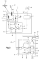
- the figure 2 schematically represents a transmission / reception installation 1 'according to a second embodiment of the invention.
- the installation 1 'of the figure 2 includes all the elements of the installation 1 of the figure 1 referenced identically: the description of these elements as made with reference to the figure 1 also applies to the common elements of the installation 1 'of the figure 2 and will not be repeated in the following.
- the installation 1 'of the figure 2 differs from that of the figure 1 in that it furthermore comprises a satellite one-way (reception) path in addition to the terrestrial forward path.
- the transmission block 9 becomes a transmission / reception block 9 integrating a reception channel RX; more specifically, the antenna 10 is also adapted for the reception of microwave radio signals transmitted by the satellite in transmission band S (for example in the band [2170 MHz-2200 MHz]) and the transmission / reception block 9 comprises in addition, a low-noise amplifier 12 for amplifying the electrical signal representative of the radio wave received in reception band S and coming from the antenna 10.
- the antenna 10 is also adapted for the reception of microwave radio signals transmitted by the satellite in transmission band S (for example in the band [2170 MHz-2200 MHz]) and the transmission / reception block 9 comprises in addition, a low-noise amplifier 12 for amplifying the electrical signal representative of the radio wave received in reception band S and coming from the antenna 10.
- the multiplexer 15 further comprises a high-pass filter 16 whose output is connected to the coupler 19 and the input is connected to the output of the low-noise amplifier 12; the high-pass filter 16 passes frequencies above 2170 MHz (thus the frequencies in the S-band receiving).
- the housing 21 further comprises a modem 23 incorporating the modulator 25, operating for example according to an SPREAD ALOHA modulated band spreading multiple random access asynchronous protocol optimized for the satellite hub to be able to use a means of eliminating interference.
- interferences such a protocol is for example described in document US2010 / 0054131 (del Rio Herrero et al. ) and a demodulator 24, operating according to the DVB-SH standard (ETSI EN 302 583 Digital Video Broadcasting (DVB); Framing structure, channel coding and modulation for Satellite Services to Handheld Devices (SH) below 3 GHz, January 2008).
- the demultiplexer 22 further comprises a high-pass filter 28 whose input is connected to the coupler 30 and the output is connected to the input of the demodulator 24; the high-pass filter 28 passes frequencies above 2170 MHz (S band in reception).
- the operating principle of the installation 1 'according to the invention is based on the use of a reception part (without emission) by terrestrial hertzian way and of a transmission / reception part in band S formed by the emission block / reception 9.
- the operation of the radio reception part and the transmission part by the block 9 is identical to that presented with reference to the figure 1 .
- the set of signals is multiplexed on the single coaxial cable 20.
- the received satellite signals in band S (here the band [2170 MHz-2200 MHz] are directly (without frequency modification) transmitted, after amplification by amplifier 12, on the cable coaxial 20 by the multiplexer 15 after filtering via the high-pass filter 16 and passing through the microwave coupler 19.
- These signals are then recovered at the microwave coupler 30 of the demultiplexer 22 and then filtered by the high-pass filter 28 before being transmitted to the DVB-SH 24 demodulator.
- the S-band satellite forward path allows (as the terrestrial reception path) to recover signaling information present in the satellite signal.
- the case comprises means (not shown) for extracting signaling information used to establish the backward transmission parameters present in a portion of the satellite signals received in the S-band.
- the invention has been more particularly described in the case of use in S-band but it can also be used in C-band.
Landscapes
- Engineering & Computer Science (AREA)
- Signal Processing (AREA)
- Computer Networks & Wireless Communication (AREA)
- Multimedia (AREA)
- Physics & Mathematics (AREA)
- Astronomy & Astrophysics (AREA)
- General Physics & Mathematics (AREA)
- Radio Relay Systems (AREA)
Abstract
Description
La présente invention concerne une installation d'émission/réception de signaux radioélectriques hyperfréquences.The present invention relates to an installation for transmitting / receiving microwave radio signals.
Actuellement, la diffusion de programmes de télévision numérique par voie terrestre (par exemple selon l'une des normes DVB-T, DVB-T2 ou DVB-T2-lite) est largement utilisée à travers le monde. De nombreux dispositifs sont installés chez des millions d'utilisateurs. Les dispositifs installés sont majoritairement des dispositifs de réception qui comportent une unité extérieure incluant une antenne de réception (par exemple une antenne « râteau » réceptrice) qui transmet des signaux radioélectriques hyperfréquences modulés à une unité intérieure communément appelée décodeur de télévision numérique terrestre ou encore STB (« Set Top Box » en anglais) par l'intermédiaire d'un câble coaxial. Le décodeur comprend un bloc de démodulation DVB-T ou DVB-T2 qui extrait un signal modulé « utile » dans le signal modulé transmis sur le câble coaxial et démodule le signal « utile » extrait. Le signal « utile » démodulé peut, par exemple, être utilisé pour l'affichage d'images vidéo sur un écran de télévision.Currently, terrestrial digital TV broadcasting (eg DVB-T, DVB-T2 or DVB-T2-lite) is widely used around the world. Many devices are installed in millions of users. The devices installed are mainly receiving devices which comprise an outdoor unit including a receiving antenna (for example a receiving "rake" antenna) which transmits modulated microwave radio signals to an indoor unit commonly known as a terrestrial digital television decoder or else STB ("Set Top Box" in English) via a coaxial cable. The decoder includes a DVB-T or DVB-T2 demodulation block which extracts a modulated signal "useful" in the modulated signal transmitted on the coaxial cable and demodulates the extracted "useful" signal. The demodulated "useful" signal may, for example, be used for displaying video images on a television screen.
Les offres de diffusion de programmes de télévision numérique par voie terrestre sont aujourd'hui essentiellement purement passives, c'est-à-dire unidirectionnelles (« one-way service » en anglais).The offers for broadcasting terrestrial digital television programs are today essentially purely passive, that is to say unidirectional ("one-way service" in English).
Il peut toutefois s'avérer utile de pouvoir offrir des services nécessitant une voie retour ; c'est le cas par exemple des services interactifs (votes, consommation de contenus à accès conditionnel par échange de clefs, commandes de nouveaux services tels que de la vidéo à la demande). En outre, cette voie retour peut trouver des applications particulièrement intéressantes dans le domaine des communications de machine à machine (« Machine to machine » en anglais) ou M2M pour contrôler certains appareils (alarme, chauffage,...) et/ou récupérer des données mesurées par des capteurs présents au sein des foyers.However, it may be useful to be able to offer services requiring a return path; this is the case, for example, of interactive services (voting, consumption of conditional access content by key exchange, orders for new services such as video on demand). In addition, this return path can find particularly interesting applications in the field of machine-to-machine (M2M) communications or M2M for controlling certain devices (alarm, heating, etc.) and / or recovering data measured by sensors in the homes.
Une solution connue à ce problème consiste à utiliser une voie retour utilisant une connexion de type ADSL fournie par des opérateurs de téléphonie fixe (RTC ou « Réseau Téléphonique Commuté ») ou une connexion de type GPRS/UMTS fournie par des opérateurs de téléphonie mobile. Cette solution nécessite donc du matériel supplémentaire important et coûteux ainsi qu'un abonnement additionnel ; par ailleurs, la commutation téléphonique n'est pas particulièrement adaptée à la transmission de messages peu volumineux tels que des messages de vote ou de commande. L'utilisation d'une solution plus appropriée, comme la technologie DVB-RCT (décrite dans le standard européen ETSI EN 301 958), a échoué pour des raisons de coût de l'infrastructure nécessaire.A known solution to this problem is to use a return channel using an ADSL type of connection provided by fixed telephony operators (PSTN or "Switched Telephone Network") or a connection. GPRS / UMTS type provided by mobile operators. This solution therefore requires important and expensive additional equipment and an additional subscription; moreover, the telephone switching is not particularly adapted to the transmission of small messages such as voting or command messages. The use of a more appropriate solution, such as the DVB-RCT technology (described in the European standard ETSI EN 301 958), failed due to the cost of the necessary infrastructure.
Dans ce contexte, la présente invention vise à fournir une installation de réception de signaux radioélectriques hyperfréquences par voie terrestre permettant également d'assurer l'émission en voie retour de signaux radioélectriques hyperfréquences de façon efficace en termes de performances, facilement adaptable à une installation préexistante, évolutive et peu coûteuse.In this context, the present invention aims to provide an installation for receiving terrestrial microwave radio signals which also makes it possible to ensure microwave transmission of microwave radio signals in an efficient manner, easily adaptable to a pre-existing installation. , scalable and inexpensive.
A cette fin, l'invention propose une installation d'émission/réception de signaux radioélectriques hyperfréquences comportant :
- une unité d'émission/réception comportant :
- ○ des moyens aptes à recevoir des signaux électriques, dits signaux électriques terrestres, issus de la transformation de signaux radioélectriques reçus par voie hertzienne terrestre ;
- ○ des moyens pour transformer des signaux électriques modulés selon un protocole à étalement de spectre, dits signaux électriques satellitaires, en signaux radioélectriques aptes à être émis par voie satellitaire ;
- ○ des moyens d'émission vers un satellite desdits signaux radioélectriques hyperfréquences obtenus après transformation desdits signaux électriques satellitaires ;
- ○ des moyens d'amplification desdits signaux électriques satellitaires ;
- un boîtier incluant un modulateur de signaux électriques selon un protocole à étalement de spectre ;
- un câble coaxial reliant l'unité d'émission/réception et le boîtier apte à :
- ○ véhiculer lesdits signaux électriques terrestres de ladite unité d'émission/réception vers ledit boîtier ;
- ○ véhiculer les signaux électriques issus dudit modulateur selon un protocole à étalement de spectre dudit boîtier vers ladite unité d'émission/réception.
- a transmitting / receiving unit comprising:
- ○ means able to receive electrical signals, called terrestrial electrical signals, resulting from the transformation of radio signals received by terrestrial hertzian means;
- Means for transforming electrical signals modulated in accordance with a spread spectrum protocol, called satellite electrical signals, into radio signals that can be transmitted by satellite;
- Means for transmitting to a satellite said microwave radioelectric signals obtained after transformation of said satellite electrical signals;
- Means for amplifying said satellite electrical signals;
- a housing including an electrical signal modulator according to a spread spectrum protocol;
- a coaxial cable connecting the transmitting / receiving unit and the housing adapted to:
- ○ conveying said terrestrial electrical signals from said transmitting / receiving unit to said housing;
- ○ convey the electrical signals from said modulator according to a spread spectrum protocol of said housing to said transmitting / receiving unit.
Grâce à l'invention, on utilise avantageusement une installation hybride avec une voie de diffusion terrestre de signaux vers les utilisateurs (par exemple dans une bande de fréquence comprise entre 470 et 862 MHz) et une voie retour satellitaire (bande de fréquences par exemple comprise entre 1.5 et 5 GHz, c'est-à-dire les fréquences de la bande S, l'utilisation de cette bande de fréquence n'étant pas limitative).Thanks to the invention, it is advantageous to use a hybrid installation with a terrestrial signal broadcasting channel to users (for example in a frequency band between 470 and 862 MHz) and a satellite return channel (for example a frequency band). between 1.5 and 5 GHz, that is to say the frequencies of the S band, the use of this frequency band not being limiting).
Les avantages d'une telle installation sont multiples. On utilise une technologie éprouvée en voie aller de diffusion vers les utilisateurs visant à transmettre des signaux de taille importante tels que des signaux de télévision et une voie retour satellitaire permettant notamment à l'utilisateur d'interagir avec la voie de diffusion et de transmettre des messages assez courts, la technique de modulation étant basée sur un protocole à étalement de spectre telle qu'un protocole asynchrone à accès aléatoire multiple à étalement de bande par modulation du type SPREAD ALOHA utilisant des techniques d'élimination d'interférences. Un tel protocole est par exemple décrit dans le document
Le système selon l'invention permet d'être très facilement (et sans surcoût important) adaptable sur une installation existante dans la mesure où il suffit de venir rajouter l'unité d'émission/réception (préférentiellement à l'extérieur de l'habitation) et le boîtier (préférentiellement à l'intérieur de l'habitation) qui viennent se connecter au câble coaxial existant. En outre, l'antenne d'émission des signaux satellitaires est une antenne (i.e. les moyens d'émission vers un satellite des signaux radioélectriques hyperfréquences) très peu coûteuse omnidirectionnelle ou avec une faible directivité (par exemple un gain d'antenne de moins de 10 dBi). Le signal émis par l'antenne pourra être reçu par un satellite ou un « collecteur » terrestre, selon la fréquence utilisée.The system according to the invention makes it possible to be very easily (and without significant additional cost) adaptable to an existing installation to the extent that it is sufficient to come to add the unit of emission / reception (preferentially outside the house ) and the housing (preferentially inside the house) that come to connect to the existing coaxial cable. In addition, the antenna for transmitting satellite signals is an antenna (ie means for transmitting to a microwave radio signals satellite) that is very inexpensive omnidirectional or with a low directivity (for example an antenna gain of less than 10 dBi). The signal transmitted by the antenna can be received by a satellite or a terrestrial "collector", according to the frequency used.
On notera par ailleurs que le système selon l'invention est très évolutif. En effet, il est tout à fait envisageable de commencer à utiliser le système en émettant tous les signaux retour vers un satellite ; à partir du moment où la capacité du satellite n'est plus suffisante, on identifie la ou les zones de service où il y a le plus de messages envoyés. Dès lors, au lieu d'utiliser directement la liaison antenne - satellite, on peut prévoir des « collecteurs » terrestres, c'est-à-dire des stations de réception terrestres, servant de relais et permettant de réduire la charge du satellite. Les signaux émis par les terminaux, sur une fréquence appropriée, seront alors reçus par les collecteurs au lieu du satellite. La capacité peut ainsi être augmentée en fonction du besoin, avec un coût proportionnel au nombre de terminaux déployés et un investissement progressif.Note also that the system according to the invention is very scalable. Indeed, it is quite possible to start using the system by sending all the return signals to a satellite; when the capacity of the satellite is no longer sufficient, we identify the service area or areas where there are the most messages sent. Therefore, instead of directly using the antenna-satellite link, it can provide terrestrial "collectors", that is to say, terrestrial receiving stations, serving as relays and to reduce the load of the satellite. The signals emitted by the terminals, on an appropriate frequency, will then be received by the collectors instead of the satellite. The capacity can be increased according to the need, with a cost proportional to the number of terminals deployed and a progressive investment.
La voie de diffusion terrestre peut être fortement intégrée à la voie retour satellitaire, puisqu'elle peut contenir, dans un des signaux multiplex émis, des informations de signalisation utiles pour le bon fonctionnement de l'installation. Ces informations peuvent inclure des paramètres d'émission à utiliser (fréquence, débit de type « symbol rate », code d'étalement), la charge du système, des clés de sécurité, ainsi que d'autres instructions pour l'installation. Le boîtier contient donc la logique nécessaire pour interpréter l'information présente dans la voie de diffusion terrestre et l'utiliser pour piloter l'émission de signaux. Comme nous le verrons par la suite, l'installation peut également comporter une voie de diffusion satellitaire optionnelle ; dans ce cas, les informations de signalisation peuvent être transmises indifféremment via les signaux satellitaires ou via les signaux terrestres.The terrestrial broadcasting channel can be strongly integrated with the satellite return channel, since it may contain, in one of the multiplex signals transmitted, signaling information useful for the proper functioning of the installation. This information may include transmit parameters to be used (frequency, symbol rate, spread code), system load, security keys, and other instructions for installation. The box therefore contains the logic necessary to interpret the information present in the terrestrial broadcasting channel and use it to control the transmission of signals. As we will see later, the installation may also include an optional satellite broadcasting channel; in this case, the signaling information can be transmitted indifferently via satellite signals or via terrestrial signals.
L'installation selon l'invention est particulièrement insolite pour l'homme du métier dans la mesure où il était difficile d'imaginer un système hybride terrestre - satellite avec une voie retour satellitaire sans ajout conséquent de matériels induisant un surcoût rédhibitoire pour l'utilisateur. C'est précisément l'utilisation d'une modulation spécifique et d'une antenne peu coûteuse qui permet de rendre attractive l'installation selon l'invention.The installation according to the invention is particularly unusual for those skilled in the art insofar as it was difficult to imagine a terrestrial-satellite hybrid system with a satellite return channel without the consequent addition of equipment inducing an unacceptable extra cost for the user. . It is precisely the use of a specific modulation and an inexpensive antenna which makes the installation according to the invention attractive.
L'installation d'émission/réception selon l'invention peut également présenter une ou plusieurs des caractéristiques ci-dessous, considérées individuellement ou selon toutes les combinaisons techniquement possibles :
- ledit modulateur de signaux électriques comporte des moyens de mis en oeuvre d'un protocole à étalement de spectre fonctionnant selon un protocole asynchrone à accès aléatoire multiple à étalement de spectre, éventuellement optimisés pour que le hub satellitaire puisse utiliser des moyens d'élimination d'interférences ;
- lesdits moyens d'émission vers un satellite desdits signaux radioélectriques hyperfréquences obtenus après transformation desdits signaux électriques satellitaires sont une antenne omnidirectionnelle ou avec une faible directivité ;
- ledit modulateur de signaux électriques selon un protocole à étalement de spectre module est apte à moduler les signaux dans une bande de fréquence intermédiaire, ladite unité d'émission réception comportant des moyens pour remonter la fréquence des signaux modulés dans ladite bande de fréquence intermédiaire vers une bande de fréquence d'émission ;
- lesdits moyens pour remonter la fréquence comportent un oscillateur local générant un signal de transposition à une fréquence d'oscillation apte à être ajoutée aux fréquences de ladite bande de fréquence intermédiaire ;
- ledit boîtier comporte des moyens pour extraire un signal d'horloge à partir d'un signal électrique et des moyens pour transmettre ledit signal d'horloge aux dits moyens pour remonter la fréquence de sorte que la fréquence dudit signal d'horloge soit apte à être ajoutée aux fréquences de ladite bande de fréquence intermédiaire ;
- l'installation comporte des moyens pour extraire, à partir des signaux électriques terrestres, des informations de signalisation pour l'établissement des paramètres d'émission.
- lesdits signaux électriques satellitaires sont modulés dans la bande de fréquences d'émission dite bande S, et plus particulièrement dans la bande [1980 MHz ; 2010 MHz] ;
- lesdits moyens de réception de signaux radioélectriques hyperfréquences transmis par voie hertzienne terrestre sont aptes à recevoir des signaux radioélectriques hyperfréquences dans la bande UHF ou VHF;
- ledit boîtier inclut un démodulateur desdits signaux électriques terrestres.
- ledit démodulateur desdits signaux électriques terrestres est apte à démoduler des signaux modulés selon la norme DVB-T ou DVB-T2 ;
- ledit boîtier comporte des moyens de connexion sans fil tels que des moyens WiFi, WiMax, BlueTooth, ZigBee ou KNX ;
- lesdits moyens de connexion sans fil sont aptes à émettre des données démodulées par ledit démodulateur et à recevoir des données à transmettre au dit modulateur ;
- lesdits moyens d'émission vers un satellite desdits signaux radioélectriques hyperfréquences sont également des moyens d'émission vers une station de réception terrestre (« collecteur ») desdits signaux radioélectriques hyperfréquences.
- said electrical signal modulator comprises means for implementing a spread spectrum protocol operating according to a spread spectrum multiple random access asynchronous protocol, possibly optimized so that the satellite hub can use elimination means of interference;
- said means for transmitting to a satellite said microwave radio signals obtained after transformation of said satellite electrical signals are an omnidirectional antenna or with a low directivity;
- said modulator of electrical signals according to a spread spectrum protocol module is adapted to modulate the signals in an intermediate frequency band, said transmitting receiving unit having means for raising the frequency of the modulated signals in said intermediate frequency band to a emission frequency band;
- said means for raising the frequency comprises a local oscillator generating a transposition signal at an oscillation frequency adapted to be added to the frequencies of said intermediate frequency band;
- said housing comprises means for extracting a clock signal from an electrical signal and means for transmitting said clock signal to said means for raising the frequency so that the frequency of said clock signal is adapted to be added to the frequencies of said intermediate frequency band;
- the installation comprises means for extracting, from terrestrial electrical signals, signaling information for setting the transmission parameters.
- said satellite electrical signals are modulated in the so-called S-band transmission frequency band, and more particularly in the band [1980 MHz; 2010 MHz];
- said means for receiving microwave radio signals transmitted by terrestrial hertzian means are capable of receiving microwave radio signals in the UHF or VHF band;
- said housing includes a demodulator of said terrestrial electrical signals.
- said demodulator of said terrestrial electrical signals is adapted to demodulate modulated signals according to the DVB-T or DVB-T2 standard;
- said housing comprises wireless connection means such as WiFi, WiMax, BlueTooth, ZigBee or KNX means;
- said wireless connection means are capable of transmitting data demodulated by said demodulator and receiving data to be transmitted to said modulator;
- said means for transmitting to a satellite said microwave radio signals are also transmission means to a terrestrial reception station ("collector") of said microwave radio signals.
La présente invention a également pour objet une unité d'émission/réception apte à être intégrée dans une installation selon l'invention comportant :
- des moyens aptes à recevoir des signaux électriques, dits signaux électriques terrestres, issus de la transformation de signaux radioélectriques reçus par voie hertzienne terrestre ;
- des moyens pour transformer des signaux électriques modulés selon un protocole à étalement de spectre, dits signaux électriques satellitaires, en signaux radioélectriques aptes à être émis par voie satellitaire ;
- des moyens d'émission vers un satellite desdits signaux radioélectriques hyperfréquences obtenus après transformation desdits signaux électriques satellitaires ;
- des moyens d'amplification desdits signaux électriques satellitaires.
- means adapted to receive electrical signals, called terrestrial electrical signals, resulting from the transformation of radio signals received by terrestrial hertzian means;
- means for transforming electrical signals modulated according to a spread spectrum protocol, said satellite electrical signals, into radio signals capable of being transmitted by satellite;
- means for transmitting to a satellite said microwave radioelectric signals obtained after transformation of said satellite electrical signals;
- means for amplifying said satellite electrical signals.
On notera que même si l'unité d'émission/réception est principalement décrite comme un dispositif unique intégrant toutes les fonctionnalités précédemment décrites, il peut également s'agir d'un agencement de plusieurs dispositifs distincts réalisant ces fonctionnalités : on peut ainsi envisager que les moyens d'émission vers le satellite (i.e. l'antenne) ne soient pas directement intégrés au même dispositif.It should be noted that even if the transmission / reception unit is mainly described as a single device integrating all the functionalities previously described, it can also be an arrangement of several separate devices performing these functions: it can thus be envisaged that the transmission means to the satellite (ie the antenna) are not directly integrated into the same device.
La présente invention a également pour objet un boîtier apte à être intégré dans une installation selon l'invention comportant un modulateur de signaux électriques selon un protocole à étalement de spectre.The present invention also relates to a housing adapted to be integrated in an installation according to the invention comprising an electric signal modulator according to a spread spectrum protocol.
Ledit boîtier comporte avantageusement un démodulateur desdits signaux électriques terrestres.Said housing advantageously comprises a demodulator of said terrestrial electrical signals.
D'autres caractéristiques et avantages de l'invention ressortiront clairement de la description qui en est donnée ci-dessous, à titre indicatif et nullement limitatif, en référence aux figures annexées, parmi lesquelles :
- la
figure 1 représente schématiquement une installation selon un premier mode de réalisation de l'invention ; - la
figure 2 représente schématiquement une installation selon un second mode de réalisation de l'invention.
- the
figure 1 schematically represents an installation according to a first embodiment of the invention; - the
figure 2 schematically represents an installation according to a second embodiment of the invention.
La
L'installation d'émission/réception 1 est apte à fonctionner avec une antenne hertzienne 3 standard (par exemple une antenne « râteau » se trouvant sur le toit d'un immeuble ou d'une habitation) permettant de recevoir des signaux en bande UHF ou VHF comportant des flux de télévision numérique terrestre codés selon un protocole de type DVB-T ou DVB-T2.The transmission / reception installation 1 is able to operate with a standard radio antenna 3 (for example a "rake" antenna located on the roof of a building or a dwelling) allowing UHF band signals to be received. or VHF with terrestrial digital television streams coded according to a DVB-T or DVB-T2 type protocol.
L'installation d'émission/réception 1 comporte :
- une unité d'émission/
réception 2 extérieure à la maison ; - un câble coaxial 20 ;
un boîtier 21 destiné à être logé à l'intérieur de la maison.
- a transmitting / receiving
unit 2 outside the house; - a
coaxial cable 20; - a
housing 21 intended to be housed inside the house.
L'antenne hertzienne 3 reçoit des signaux DVB-T ou DVB-T2, par exemple en bande UHF (bande 470 - 862 MHz).The
L'unité d'émission/réception 2 comporte :
- des moyens d'entrée 4 aptes à recevoir les signaux électriques terrestres reçues par l'antenne 3 (l'antenne et les moyens d'entrée 4 sont par exemple reliés par un câble coaxial 34) ;
un bloc d'émission 9 ;- un multiplexeur de signaux radioélectriques 15.
- input means 4 adapted to receive terrestrial electrical signals received by the antenna 3 (the antenna and the input means 4 are for example connected by a coaxial cable 34);
- an
emission block 9; - a multiplexer of radio signals 15.
Le bloc d'émission 9 intègre une voie d'émission TX.The
Plus spécifiquement, le bloc d'émission 9 comporte
une antenne 10 omnidirectionnelle ou quasi omnidirectionnelle (i.e. une antenne avec une faible directivité, par exemple présentant un gain d'antenne de moins de 10 dBi) apte à transformer des signaux électriques en bande S d'émission (par exemple dans la bande [1980 MHz - 2010 MHz]) en signaux radioélectriques hyperfréquences et à transmettre ces signaux versun satellite 100 en bande S ;- un amplificateur du type à état solide 11 ou SSPA (« Solid State Power Amplifier ») apte à amplifier un signal électrique dans la bande de fréquences [1980 MHz - 2010 MHz] à une puissance comprise entre 50 mW et 1 W puis à transmettre ce signal amplifié vers l'antenne 10 ;
cet amplificateur 11 va amplifier les signaux destinés à être transmis en bande S vers lesatellite 100 ; - un oscillateur local 14 générant un signal de transposition à une fréquence d'oscillation par exemple de 1610 MHz ;
- un mélangeur de fréquence 13 ayant une première entrée pour recevoir des signaux électriques dans une bande de fréquences intermédiaires (par exemple la bande [370 MHz - 400 MHz]) et une seconde entrée pour recevoir le signal généré par l'oscillateur local 14 de sorte qu'il produit un signal électrique dans la bande de fréquence [1980 MHz - 2010 MHz].
- an omnidirectional or quasi-omnidirectional antenna (ie an antenna with a low directivity, for example having an antenna gain of less than 10 dBi) capable of transforming electrical signals into an emission band S (for example in the band [1980 MHz - 2010 MHz]) in microwave radio signals and transmit these signals to a
satellite 100 in the S band; - an amplifier of
solid state type 11 or SSPA ("Solid State Power Amplifier") able to amplify an electrical signal in the frequency band [1980 MHz - 2010 MHz] at a power of between 50 mW and 1 W then to transmit this amplified signal to theantenna 10; thisamplifier 11 will amplify the signals intended to be transmitted in the S band to thesatellite 100; - a
local oscillator 14 generating a transposition signal at an oscillation frequency, for example 1610 MHz; - a
frequency mixer 13 having a first input for receiving electrical signals in an intermediate frequency band (for example the band [370 MHz - 400 MHz]) and a second input for receiving the signal generated by thelocal oscillator 14 so that it produces an electrical signal in the frequency band [1980 MHz - 2010 MHz].
Le multiplexeur 15 comporte :
- un filtre passe-
bas 18 dont la sortie est reliée à l'entrée du mélangeur de fréquence 13 et l'entrée est reliée à un coupleur hyperfréquences 19; le filtre passe-bas 18 laisse ici passer les fréquences inférieures à 400 MHz (donc les fréquences dans la bande de fréquences intermédiaires dont nous parlerons par la suite) ; - un filtre passe-
bande 17 dont la sortie est reliée au coupleur 19 et l'entrée est reliée à la sortie des moyens d'entrée 4 aptes à recevoir les signaux électriques terrestres reçuspar l'antenne 3 ; le filtre passe-bande 17 laisse passer les fréquences comprises entre 470 et 862 MHz (dans les fréquences dans la bande UHF).
- a low-
pass filter 18 whose output is connected to the input of thefrequency mixer 13 and the input is connected to amicrowave coupler 19; the low-pass filter 18 passes here frequencies below 400 MHz (therefore the frequencies in the intermediate frequency band which we will discuss later); - a
bandpass filter 17 whose output is connected to thecoupler 19 and the input is connected to the output of the input means 4 able to receive the terrestrial electrical signals received by theantenna 3; thefilter bandpass 17 passes the frequencies between 470 and 862 MHz (in the frequencies in the UHF band).
Le boîtier 21 comporte :
un démultiplexeur 22 ;un modulateur 25 fonctionnant par exemple suivant un protocole asynchrone à accès aléatoire multiple à étalement de bande par modulation du type SPREAD ALOHA optimisé pour que le hub satellitaire puisse utiliser des moyens d'élimination d'interférences (un tel protocole est par exemple décrit dans le documentUS2010/0054131 (del Rio Herrero et al. - des moyens 26 de connexion sans fil à un réseau local du type WiFi, WiMax, BlueTooth, ZigBee ou KNX, ou de connexion filaire à un réseau local du type Ethernet ou similaire ;
- une connexion d'entrée/
sortie 32 de type USB apte à délivrer des signaux vers un décodeur de télévision numérique 31 dit encore STB (« Set Top Box » en anglais) ; un démodulateur 33 fonctionnant selon la norme DVB-T (décrite dans la norme ETSI EN 300 744 « Digital Video Broadcasting (DVB); Framing structure, channel coding and modulation for digital terrestrial television ») ou DVB-T2 (décrite dans la norme ETSI EN 302 755 « Digital Video Broadcasting (DVB); Frame structure channel coding and modulation for a second generation digital terrestrial television broadcasting system (DVB-T2) », les extensions de la norme DVB-T2 telles que DVB-T2-lite étant décrites dans le « DVB BlueBook A122 »).
- a
demultiplexer 22; - a
modulator 25 operating, for example, according to an SPREAD ALOHA modulated band spreading multiple random access asynchronous protocol optimized for the satellite hub to be able to use interference elimination means (such a protocol is for example described in FIG. documentUS2010 / 0054131 (del Rio Herrero et al. - means 26 for wireless connection to a local network of WiFi, WiMax, BlueTooth, ZigBee or KNX type, or wired connection to an Ethernet type local network or the like;
- a USB input /
output connection 32 capable of delivering signals to adigital television decoder 31, also known as STB ("Set Top Box"); - a
demodulator 33 operating according to the DVB-T standard (described in the ETSI EN 300 744 standard "Digital Video Broadcasting (DVB); Framing structure, channel coding and modulation for digital terrestrial television") or DVB-T2 (described in the ETSI standard EN 302 755 "Digital Video Broadcasting (DVB);" the DVB-T2 extensions such as DVB-T2-lite are described in the "DVB BlueBook A122").
Le démultiplexeur 22 comporte :
- un filtre passe-
bas 29 dont la sortie est reliée à un coupleur hyperfréquences 30 et l'entrée est reliée à la sortie du modulateur 25; le filtre passe-bas 29 laisse ici passer les fréquences inférieures à 400 MHz (fréquences intermédiaires) ; - un filtre passe-
bande 27 dont l'entrée est reliée au coupleur 30 et la sortie est reliée au démodulateur 33 apte à alimenter le décodeur 31 ; le filtre passe-bande 27 laisse passer les fréquences comprises entre 470 et 862 MHz (bande UHF).
- a low-
pass filter 29 whose output is connected to amicrowave coupler 30 and the input is connected to the output of themodulator 25; the low-pass filter 29 passes here frequencies below 400 MHz (intermediate frequencies); - a band-
pass filter 27 whose input is connected to thecoupler 30 and the output is connected to thedemodulator 33 able to supply thedecoder 31; thebandpass filter 27 passes frequencies between 470 and 862 MHz (UHF band).
Le câble coaxial 20 relie le boîtier 21 via son démultiplexeur 22 et l'unité d'émission/réception 2 via son multiplexeur 15.The
Le principe de fonctionnement de l'installation 1 selon l'invention repose sur l'utilisation d'une partie réception (sans émission) par voie hertzienne terrestre formée par l'antenne « râteau » 3 et les moyens d'entrée 4 aptes à recevoir les signaux électriques terrestres reçus par l'antenne 3 et d'une partie émission en bande S formée par le bloc d'émission 9. La partie émission en bande S constitue une voie retour permettant la mise en place de services interactifs (votes, consommation de contenus à accès conditionnel par échange de clefs, commandes de nouveaux services tels que de la vidéo à la demande) ou de services M2M (contrôle d'appareils domestiques, surveillance, monitorage d'un paramètre mesuré par un capteur) avec un ajout de matériel relativement limité et peu coûteux sur une installation existante. L'antenne omnidirectionnelle 10 permet de transmettre les signaux en bande S soit directement vers le satellite 100 ou vers des collecteurs terrestres 101 dans l'hypothèse d'une augmentation de la capacité (dans ce cas, l'antenne 10 devra être préférentiellement légèrement directionnelle de façon à atteindre le collecteur 101).The operating principle of the installation 1 according to the invention is based on the use of a reception part (without emission) by terrestrial hertzian way formed by the antenna "rake" 3 and the input means 4 able to receive the terrestrial electrical signals received by the
L'ensemble des signaux est multiplexé sur le seul câble coaxial 20.The set of signals is multiplexed on the single
Les signaux terrestres reçus par l'antenne 3 puis les moyens d'entrée 4 sont transmis par le multiplexeur 15 sur le câble coaxial 20 après filtrage par le filtre passe-bande 17. Ces signaux sont ensuite récupérés au niveau du coupleur hyperfréquences 30 du démultiplexeur 22 puis filtrés par le filtre passe-bande 27 avant d'être transmis au démodulateur 33 DVB-T ou DVB-T2 puis à la STB 31 via la sortie USB 32, et/ou en parallèle directement à la STB 31 via un câble coaxial 35.The terrestrial signals received by the
Les signaux à émettre en bande S sont modulés par le modulateur 25 sur la bande de fréquences intermédiaires (ici [370 MHz - 400 MHz] donnée à titre purement illustratif) et sont transmis sur le câble coaxial 20 par le démultiplexeur 22 après avoir été filtrés par le filtre passe bas 29. Ils sont ensuite transposés en fréquence vers la bande S en émission et amplifiés par l'amplificateur 11. On notera que la bande de fréquences intermédiaires est choisie de façon à limiter les pertes sur le câble coaxial. Si la longueur du câble est limitée, il serait toutefois possible de transmettre les signaux directement sur le câble coaxial sur la bande [1980 MHz - 2010 MHz] sans utiliser de bande de fréquences intermédiaires puisque les bandes de fréquences utilisées respectivement pour la bande S en voie aller et retour et pour la bande UHF sont disjointes, permettant donc d'éviter les interférences entre les signaux transmis sur le même câble.The signals to be transmitted in the S band are modulated by the
La bande de fréquences intermédiaires choisie présente toutefois l'avantage d'être compatible avec la bande passante d'un câble coaxial standard.The intermediate frequency band chosen, however, has the advantage of being compatible with the bandwidth of a standard coaxial cable.
La voie aller de réception terrestre en UHF permet par ailleurs de récupérer des informations utiles. Il peut s'agir par exemple de la fréquence ou de la largeur de bande qui seront utilisées en voie retour en bande S. Il peut s'agir également de mises à jour liées à la modulation/démodulation utilisée par le modem 23. On peut également récupérer un signal d'horloge très stable (i.e. avec une erreur en fréquence inférieure à 1 kHz) : ce signal d'horloge peut ensuite être transmis vers le bloc d'émission/réception afin d'être utilisé pour la transposition en fréquence à la place de l'oscillateur local moins précis. En d'autres termes, la voie aller de diffusion terrestre peut être fortement intégrée à la voie retour satellitaire puisque les signaux multiplex émis par voie terrestre peuvent contenir des informations de signalisation utiles pour le bon fonctionnement de l'installation. Ces informations peuvent inclure des paramètres d'émission à utiliser (fréquence, débit de type « symbol rate », code d'étalement), la charge du système, des clés de sécurité, ainsi que d'autres instructions pour l'installation. Le boîtier contient donc la logique nécessaire pour interpréter l'information présente dans la voie de diffusion terrestre et l'utiliser pour piloter l'émission de signaux. Ce dernier point suppose que le boîtier comporte des moyens (non représentés) pour extraire des informations de signalisation utilisées pour établir les paramètres d'émission en voie retour présentes dans une partie des signaux électriques terrestres.The UHF terrestrial reception pathway also makes it possible to retrieve useful information. This may be, for example, the frequency or the bandwidth that will be used in the S-band return channel. It may also be updates related to the modulation / demodulation used by the
Une seconde application particulièrement intéressante de l'installation selon l'invention concerne le domaine du M2M. Dans ce cas, la voie retour en bande S peut être utilisée pour transmettre des informations provenant d'un appareil se trouvant dans la maison tel qu'un système d'alarme ; ainsi, lorsque le système d'alarme se déclenche, un signal est transmis par le système d'alarme aux moyens de connexion sans fil 26 (par exemple des moyens fonctionnant en ZigBee) et un message indiquant la mise en route de l'alarme est transmis sur la voie retour en bande S.A second particularly interesting application of the installation according to the invention relates to the field of M2M. In this case, the S-band return channel can be used to transmit information from a device in the home such as an alarm system; thus, when the alarm system is triggered, a signal is transmitted by the alarm system to the wireless connection means 26 (for example means operating in ZigBee) and a message indicating the start of the alarm is transmitted on the return channel in S.
La
L'installation 1' de la
L'installation 1' de la
Pour ce faire, le bloc d'émission 9 devient un bloc 9 d'émission/réception intégrant une voie de réception RX ; plus spécifiquement, l'antenne 10 est également adaptée pour la réception de signaux radioélectriques hyperfréquences émis par le satellite en bande S de transmission (par exemple dans la bande [2170 MHz - 2200 MHz]) et le bloc d'émission/réception 9 comporte en outre un amplificateur à faible bruit 12 pour amplifier le signal électrique représentatif de l'onde radioélectrique reçue en bande S de réception et provenant de l'antenne 10.For this purpose, the
Le multiplexeur 15 comporte en outre un filtre passe-haut 16 dont la sortie est reliée au coupleur 19 et l'entrée est reliée à la sortie de l'amplificateur faible bruit 12 ; le filtre passe-haut 16 laisse passer les fréquences supérieures à 2170 MHz (donc les fréquences dans la bande S en réception).The
Le boîtier 21 comporte en outre un modem 23 intégrant le modulateur 25, fonctionnant par exemple suivant un protocole asynchrone à accès aléatoire multiple à étalement de bande par modulation du type SPREAD ALOHA optimisé pour que le hub satellitaire puisse utiliser des moyens d'élimination d'interférences (un tel protocole est par exemple décrit dans le document
Le démultiplexeur 22 comporte en outre un filtre passe-haut 28 dont l'entrée est reliée au coupleur 30 et la sortie est reliée à l'entrée du démodulateur 24 ; le filtre passe-haut 28 laisse passer les fréquences supérieures à 2170 MHz (bande S en réception).The
Le principe de fonctionnement de l'installation 1' selon l'invention repose sur l'utilisation d'une partie réception (sans émission) par voie hertzienne terrestre et d'une partie émission/réception en bande S formée par le bloc d'émission/réception 9. Le fonctionnement de la partie réception par voie hertzienne et de la partie émission par le bloc 9 est identique à celui présenté en référence à la
L'ensemble des signaux est multiplexé sur le seul câble coaxial 20.The set of signals is multiplexed on the single
S'agissant de la partie réception du bloc 9, les signaux satellitaires reçus en bande S (ici la bande [2170 MHz -2200 MHz] sont directement (sans modification de fréquence) transmis, après amplification par l'amplificateur 12, sur le câble coaxial 20 par le multiplexeur 15 après filtrage via le filtre passe-haut 16 et passage par le coupleur hyperfréquences 19. Ces signaux sont ensuite récupérés au niveau du coupleur hyperfréquences 30 du démultiplexeur 22 puis filtrés par le filtre passe-haut 28 avant d'être transmis au démodulateur DVB-SH 24.As regards the reception part of
On notera qu'on n'utilise pas de bande de fréquences intermédiaires pour les signaux reçus en bande S, la fréquence de ces derniers étant directement compatibles avec la bande passante du câble 20. Même si l'installation selon l'invention utilise avantageusement la bande S en émission, l'installation 1' selon l'invention permet également d'utiliser la bande S en réception.It will be noted that no intermediate frequency band is used for the signals received in the S band, the frequency of these latter being directly compatible with the bandwidth of the
On notera également que, selon le mode de réalisation de la
Bien entendu, l'invention n'est pas limitée au mode de réalisation qui vient d'être décrit.Of course, the invention is not limited to the embodiment just described.
Ainsi, l'invention a été plus particulièrement décrite dans le cas d'une utilisation en bande S mais elle peut également être utilisée en bande C.Thus, the invention has been more particularly described in the case of use in S-band but it can also be used in C-band.
Claims (14)
Applications Claiming Priority (1)
| Application Number | Priority Date | Filing Date | Title |
|---|---|---|---|
| FR1159759A FR2982102B1 (en) | 2011-10-27 | 2011-10-27 | TRANSMITTING / RECEIVING RADIO SIGNAL INSTALLATION |
Publications (2)
| Publication Number | Publication Date |
|---|---|
| EP2587700A1 true EP2587700A1 (en) | 2013-05-01 |
| EP2587700B1 EP2587700B1 (en) | 2018-12-19 |
Family
ID=47040599
Family Applications (1)
| Application Number | Title | Priority Date | Filing Date |
|---|---|---|---|
| EP12189897.7A Active EP2587700B1 (en) | 2011-10-27 | 2012-10-25 | Installation for emission/reception of radio signals |
Country Status (4)
| Country | Link |
|---|---|
| US (1) | US8976841B2 (en) |
| EP (1) | EP2587700B1 (en) |
| ES (1) | ES2712561T3 (en) |
| FR (1) | FR2982102B1 (en) |
Families Citing this family (4)
| Publication number | Priority date | Publication date | Assignee | Title |
|---|---|---|---|---|
| FR2984641B1 (en) * | 2011-12-15 | 2014-06-13 | Eutelsat Sa | TRANSMITTING / RECEIVING RADIO SIGNAL INSTALLATION |
| FR3019412B1 (en) * | 2014-04-01 | 2016-04-29 | Eutelsat Sa | METHOD FOR ESTABLISHING RADIO FREQUENCY LINKS |
| US10419066B1 (en) * | 2017-10-05 | 2019-09-17 | Harmonic, Inc. | Remote radio frequency (RF) AGC loop |
| CN109413467A (en) * | 2018-12-17 | 2019-03-01 | 深圳市凯利华电子有限公司 | A kind of high practicability DVB-T2TVDongle DTV receiver |
Citations (3)
| Publication number | Priority date | Publication date | Assignee | Title |
|---|---|---|---|---|
| WO1996026597A1 (en) * | 1995-02-24 | 1996-08-29 | Scientific-Atlanta, Inc. | Antenna apparatus and method in satellite reverse path communication in direct-to-home subscription information systems |
| WO2002001781A2 (en) * | 2000-06-23 | 2002-01-03 | Terayon Communications Systems, Inc. | A process for supplying video from a headend |
| US20100054131A1 (en) | 2008-08-26 | 2010-03-04 | Agence Spatiale Europeenne | Methods, apparatuses and system for asynchronous spread-spectrum communication |
Family Cites Families (5)
| Publication number | Priority date | Publication date | Assignee | Title |
|---|---|---|---|---|
| FR2752352B1 (en) * | 1996-08-12 | 1998-10-23 | Thomson Multimedia Sa | INTERACTIVE SATELLITE TELEVISION SYSTEM |
| US6650869B2 (en) * | 2000-04-14 | 2003-11-18 | Hughes Electronics Corporation | System and method for managing return channel bandwidth in a two-way satellite system |
| US6909896B2 (en) * | 2001-03-20 | 2005-06-21 | Shiron Satellite Communications (1996) Ltd. | Apparatus and method for two-way data communication via satellite |
| US20050068915A1 (en) * | 2003-09-10 | 2005-03-31 | Wi Networks Inc. | Wireless infrastructure for broadcasting with return channel |
| EP2174382A1 (en) * | 2007-07-25 | 2010-04-14 | Jast SA | Omni-directional antenna for mobile satellite broadcasting applications |
-
2011
- 2011-10-27 FR FR1159759A patent/FR2982102B1/en active Active
-
2012
- 2012-10-25 EP EP12189897.7A patent/EP2587700B1/en active Active
- 2012-10-25 ES ES12189897T patent/ES2712561T3/en active Active
- 2012-10-26 US US13/661,192 patent/US8976841B2/en active Active
Patent Citations (3)
| Publication number | Priority date | Publication date | Assignee | Title |
|---|---|---|---|---|
| WO1996026597A1 (en) * | 1995-02-24 | 1996-08-29 | Scientific-Atlanta, Inc. | Antenna apparatus and method in satellite reverse path communication in direct-to-home subscription information systems |
| WO2002001781A2 (en) * | 2000-06-23 | 2002-01-03 | Terayon Communications Systems, Inc. | A process for supplying video from a headend |
| US20100054131A1 (en) | 2008-08-26 | 2010-03-04 | Agence Spatiale Europeenne | Methods, apparatuses and system for asynchronous spread-spectrum communication |
Also Published As
| Publication number | Publication date |
|---|---|
| US20130114644A1 (en) | 2013-05-09 |
| EP2587700B1 (en) | 2018-12-19 |
| US8976841B2 (en) | 2015-03-10 |
| FR2982102A1 (en) | 2013-05-03 |
| ES2712561T3 (en) | 2019-05-13 |
| FR2982102B1 (en) | 2013-12-20 |
Similar Documents
| Publication | Publication Date | Title |
|---|---|---|
| EP2908445B1 (en) | Reception of radio frequency signals, for example broadcast signals received from a satellite, with an interactive return link using a spread spectrum protocol. | |
| EP2587700B1 (en) | Installation for emission/reception of radio signals | |
| WO2006009197A1 (en) | Optical signal transmission apparatus, system and method | |
| FR2954869A1 (en) | TRANSMITTING / RECEIVING SATELLITE SIGNALS | |
| CA2889329A1 (en) | Method for the recovery of content corresponding to a url address by a client device | |
| EP1614295A1 (en) | Converter and method for converting digital signals received in the form of modulated and multiplexed signals | |
| FR2762178A1 (en) | METHOD AND SYSTEM FOR DISTRIBUTING VIDEO SERVICES | |
| EP2928088B1 (en) | Method for establishing a satellite radiofrequency link with a forward and a return path using the same frequency band allowing operation of the satellite amplificator chain at saturation. | |
| WO2008034737A1 (en) | Multi-input terrestrial repeater for a contents broadcasting system | |
| EP3900204B1 (en) | Repeating device and system for extending the coverage of a wi-fi access point | |
| EP3900219B1 (en) | Method for providing a mobile radio connection within an enclosed space by means of an external television antenna and related system | |
| KR101190339B1 (en) | Apparatus and method for hybrid transmission of combining passive optical network and hybrid fiber coaxial network for data and broadcasting service | |
| FR2656188A1 (en) | Wired network installation for distributing programmes and for digital communication, and terminal for such an installation | |
| FR2857189A1 (en) | TRANSCODER FOR CABLE NETWORK HEAD | |
| FR2680935A1 (en) | Installation with a wired network for distributing audiovisual programmes and for digital communication with a digital data bridge | |
| FR2944169A1 (en) | Universal digital infrared remote control extender device for digital TV application, has mixer and oscillator to transform envelope signal into infrared remote control signal, and LED to transmit infrared signal to audio/video sources | |
| FR2988939A1 (en) | ALTERNATE HYBRID DIFFUSION | |
| FR2879390A1 (en) | MULTIBAND MICROWAVE TERMINAL | |
| EP1865621A1 (en) | Repeater of mobile telephony radio frequency signals |
Legal Events
| Date | Code | Title | Description |
|---|---|---|---|
| PUAI | Public reference made under article 153(3) epc to a published international application that has entered the european phase |
Free format text: ORIGINAL CODE: 0009012 |
|
| AK | Designated contracting states |
Kind code of ref document: A1 Designated state(s): AL AT BE BG CH CY CZ DE DK EE ES FI FR GB GR HR HU IE IS IT LI LT LU LV MC MK MT NL NO PL PT RO RS SE SI SK SM TR |
|
| AX | Request for extension of the european patent |
Extension state: BA ME |
|
| 17P | Request for examination filed |
Effective date: 20131024 |
|
| RBV | Designated contracting states (corrected) |
Designated state(s): AL AT BE BG CH CY CZ DE DK EE ES FI FR GB GR HR HU IE IS IT LI LT LU LV MC MK MT NL NO PL PT RO RS SE SI SK SM TR |
|
| STAA | Information on the status of an ep patent application or granted ep patent |
Free format text: STATUS: EXAMINATION IS IN PROGRESS |
|
| 17Q | First examination report despatched |
Effective date: 20170717 |
|
| GRAP | Despatch of communication of intention to grant a patent |
Free format text: ORIGINAL CODE: EPIDOSNIGR1 |
|
| STAA | Information on the status of an ep patent application or granted ep patent |
Free format text: STATUS: GRANT OF PATENT IS INTENDED |
|
| RIC1 | Information provided on ipc code assigned before grant |
Ipc: H04H 60/90 20080101ALI20180620BHEP Ipc: H04N 21/61 20110101ALI20180620BHEP Ipc: H04J 13/00 20110101AFI20180620BHEP |
|
| INTG | Intention to grant announced |
Effective date: 20180711 |
|
| GRAS | Grant fee paid |
Free format text: ORIGINAL CODE: EPIDOSNIGR3 |
|
| GRAA | (expected) grant |
Free format text: ORIGINAL CODE: 0009210 |
|
| STAA | Information on the status of an ep patent application or granted ep patent |
Free format text: STATUS: THE PATENT HAS BEEN GRANTED |
|
| AK | Designated contracting states |
Kind code of ref document: B1 Designated state(s): AL AT BE BG CH CY CZ DE DK EE ES FI FR GB GR HR HU IE IS IT LI LT LU LV MC MK MT NL NO PL PT RO RS SE SI SK SM TR |
|
| REG | Reference to a national code |
Ref country code: GB Ref legal event code: FG4D Free format text: NOT ENGLISH |
|
| REG | Reference to a national code |
Ref country code: CH Ref legal event code: EP |
|
| REG | Reference to a national code |
Ref country code: IE Ref legal event code: FG4D Free format text: LANGUAGE OF EP DOCUMENT: FRENCH |
|
| REG | Reference to a national code |
Ref country code: DE Ref legal event code: R096 Ref document number: 602012054808 Country of ref document: DE |
|
| REG | Reference to a national code |
Ref country code: AT Ref legal event code: REF Ref document number: 1079831 Country of ref document: AT Kind code of ref document: T Effective date: 20190115 |
|
| REG | Reference to a national code |
Ref country code: NL Ref legal event code: FP |
|
| PG25 | Lapsed in a contracting state [announced via postgrant information from national office to epo] |
Ref country code: LV Free format text: LAPSE BECAUSE OF FAILURE TO SUBMIT A TRANSLATION OF THE DESCRIPTION OR TO PAY THE FEE WITHIN THE PRESCRIBED TIME-LIMIT Effective date: 20181219 Ref country code: HR Free format text: LAPSE BECAUSE OF FAILURE TO SUBMIT A TRANSLATION OF THE DESCRIPTION OR TO PAY THE FEE WITHIN THE PRESCRIBED TIME-LIMIT Effective date: 20181219 Ref country code: LT Free format text: LAPSE BECAUSE OF FAILURE TO SUBMIT A TRANSLATION OF THE DESCRIPTION OR TO PAY THE FEE WITHIN THE PRESCRIBED TIME-LIMIT Effective date: 20181219 Ref country code: NO Free format text: LAPSE BECAUSE OF FAILURE TO SUBMIT A TRANSLATION OF THE DESCRIPTION OR TO PAY THE FEE WITHIN THE PRESCRIBED TIME-LIMIT Effective date: 20190319 Ref country code: FI Free format text: LAPSE BECAUSE OF FAILURE TO SUBMIT A TRANSLATION OF THE DESCRIPTION OR TO PAY THE FEE WITHIN THE PRESCRIBED TIME-LIMIT Effective date: 20181219 Ref country code: BG Free format text: LAPSE BECAUSE OF FAILURE TO SUBMIT A TRANSLATION OF THE DESCRIPTION OR TO PAY THE FEE WITHIN THE PRESCRIBED TIME-LIMIT Effective date: 20190319 |
|
| REG | Reference to a national code |
Ref country code: LT Ref legal event code: MG4D |
|
| REG | Reference to a national code |
Ref country code: ES Ref legal event code: FG2A Ref document number: 2712561 Country of ref document: ES Kind code of ref document: T3 Effective date: 20190513 |
|
| REG | Reference to a national code |
Ref country code: AT Ref legal event code: MK05 Ref document number: 1079831 Country of ref document: AT Kind code of ref document: T Effective date: 20181219 |
|
| PG25 | Lapsed in a contracting state [announced via postgrant information from national office to epo] |
Ref country code: RS Free format text: LAPSE BECAUSE OF FAILURE TO SUBMIT A TRANSLATION OF THE DESCRIPTION OR TO PAY THE FEE WITHIN THE PRESCRIBED TIME-LIMIT Effective date: 20181219 Ref country code: AL Free format text: LAPSE BECAUSE OF FAILURE TO SUBMIT A TRANSLATION OF THE DESCRIPTION OR TO PAY THE FEE WITHIN THE PRESCRIBED TIME-LIMIT Effective date: 20181219 Ref country code: SE Free format text: LAPSE BECAUSE OF FAILURE TO SUBMIT A TRANSLATION OF THE DESCRIPTION OR TO PAY THE FEE WITHIN THE PRESCRIBED TIME-LIMIT Effective date: 20181219 Ref country code: GR Free format text: LAPSE BECAUSE OF FAILURE TO SUBMIT A TRANSLATION OF THE DESCRIPTION OR TO PAY THE FEE WITHIN THE PRESCRIBED TIME-LIMIT Effective date: 20190320 |
|
| PG25 | Lapsed in a contracting state [announced via postgrant information from national office to epo] |
Ref country code: PL Free format text: LAPSE BECAUSE OF FAILURE TO SUBMIT A TRANSLATION OF THE DESCRIPTION OR TO PAY THE FEE WITHIN THE PRESCRIBED TIME-LIMIT Effective date: 20181219 Ref country code: PT Free format text: LAPSE BECAUSE OF FAILURE TO SUBMIT A TRANSLATION OF THE DESCRIPTION OR TO PAY THE FEE WITHIN THE PRESCRIBED TIME-LIMIT Effective date: 20190419 Ref country code: CZ Free format text: LAPSE BECAUSE OF FAILURE TO SUBMIT A TRANSLATION OF THE DESCRIPTION OR TO PAY THE FEE WITHIN THE PRESCRIBED TIME-LIMIT Effective date: 20181219 |
|
| PG25 | Lapsed in a contracting state [announced via postgrant information from national office to epo] |
Ref country code: RO Free format text: LAPSE BECAUSE OF FAILURE TO SUBMIT A TRANSLATION OF THE DESCRIPTION OR TO PAY THE FEE WITHIN THE PRESCRIBED TIME-LIMIT Effective date: 20181219 Ref country code: IS Free format text: LAPSE BECAUSE OF FAILURE TO SUBMIT A TRANSLATION OF THE DESCRIPTION OR TO PAY THE FEE WITHIN THE PRESCRIBED TIME-LIMIT Effective date: 20190419 Ref country code: SM Free format text: LAPSE BECAUSE OF FAILURE TO SUBMIT A TRANSLATION OF THE DESCRIPTION OR TO PAY THE FEE WITHIN THE PRESCRIBED TIME-LIMIT Effective date: 20181219 Ref country code: EE Free format text: LAPSE BECAUSE OF FAILURE TO SUBMIT A TRANSLATION OF THE DESCRIPTION OR TO PAY THE FEE WITHIN THE PRESCRIBED TIME-LIMIT Effective date: 20181219 Ref country code: SK Free format text: LAPSE BECAUSE OF FAILURE TO SUBMIT A TRANSLATION OF THE DESCRIPTION OR TO PAY THE FEE WITHIN THE PRESCRIBED TIME-LIMIT Effective date: 20181219 |
|
| REG | Reference to a national code |
Ref country code: DE Ref legal event code: R097 Ref document number: 602012054808 Country of ref document: DE |
|
| PLBE | No opposition filed within time limit |
Free format text: ORIGINAL CODE: 0009261 |
|
| STAA | Information on the status of an ep patent application or granted ep patent |
Free format text: STATUS: NO OPPOSITION FILED WITHIN TIME LIMIT |
|
| PG25 | Lapsed in a contracting state [announced via postgrant information from national office to epo] |
Ref country code: AT Free format text: LAPSE BECAUSE OF FAILURE TO SUBMIT A TRANSLATION OF THE DESCRIPTION OR TO PAY THE FEE WITHIN THE PRESCRIBED TIME-LIMIT Effective date: 20181219 Ref country code: DK Free format text: LAPSE BECAUSE OF FAILURE TO SUBMIT A TRANSLATION OF THE DESCRIPTION OR TO PAY THE FEE WITHIN THE PRESCRIBED TIME-LIMIT Effective date: 20181219 |
|
| 26N | No opposition filed |
Effective date: 20190920 |
|
| PG25 | Lapsed in a contracting state [announced via postgrant information from national office to epo] |
Ref country code: SI Free format text: LAPSE BECAUSE OF FAILURE TO SUBMIT A TRANSLATION OF THE DESCRIPTION OR TO PAY THE FEE WITHIN THE PRESCRIBED TIME-LIMIT Effective date: 20181219 |
|
| PG25 | Lapsed in a contracting state [announced via postgrant information from national office to epo] |
Ref country code: TR Free format text: LAPSE BECAUSE OF FAILURE TO SUBMIT A TRANSLATION OF THE DESCRIPTION OR TO PAY THE FEE WITHIN THE PRESCRIBED TIME-LIMIT Effective date: 20181219 |
|
| PG25 | Lapsed in a contracting state [announced via postgrant information from national office to epo] |
Ref country code: MC Free format text: LAPSE BECAUSE OF FAILURE TO SUBMIT A TRANSLATION OF THE DESCRIPTION OR TO PAY THE FEE WITHIN THE PRESCRIBED TIME-LIMIT Effective date: 20181219 |
|
| REG | Reference to a national code |
Ref country code: CH Ref legal event code: PL |
|
| PG25 | Lapsed in a contracting state [announced via postgrant information from national office to epo] |
Ref country code: CH Free format text: LAPSE BECAUSE OF NON-PAYMENT OF DUE FEES Effective date: 20191031 Ref country code: LI Free format text: LAPSE BECAUSE OF NON-PAYMENT OF DUE FEES Effective date: 20191031 |
|
| PG25 | Lapsed in a contracting state [announced via postgrant information from national office to epo] |
Ref country code: IE Free format text: LAPSE BECAUSE OF NON-PAYMENT OF DUE FEES Effective date: 20191025 |
|
| PG25 | Lapsed in a contracting state [announced via postgrant information from national office to epo] |
Ref country code: CY Free format text: LAPSE BECAUSE OF FAILURE TO SUBMIT A TRANSLATION OF THE DESCRIPTION OR TO PAY THE FEE WITHIN THE PRESCRIBED TIME-LIMIT Effective date: 20181219 |
|
| PG25 | Lapsed in a contracting state [announced via postgrant information from national office to epo] |
Ref country code: MT Free format text: LAPSE BECAUSE OF FAILURE TO SUBMIT A TRANSLATION OF THE DESCRIPTION OR TO PAY THE FEE WITHIN THE PRESCRIBED TIME-LIMIT Effective date: 20181219 Ref country code: HU Free format text: LAPSE BECAUSE OF FAILURE TO SUBMIT A TRANSLATION OF THE DESCRIPTION OR TO PAY THE FEE WITHIN THE PRESCRIBED TIME-LIMIT; INVALID AB INITIO Effective date: 20121025 |
|
| PG25 | Lapsed in a contracting state [announced via postgrant information from national office to epo] |
Ref country code: MK Free format text: LAPSE BECAUSE OF FAILURE TO SUBMIT A TRANSLATION OF THE DESCRIPTION OR TO PAY THE FEE WITHIN THE PRESCRIBED TIME-LIMIT Effective date: 20181219 |
|
| PGFP | Annual fee paid to national office [announced via postgrant information from national office to epo] |
Ref country code: NL Payment date: 20231027 Year of fee payment: 12 |
|
| PGFP | Annual fee paid to national office [announced via postgrant information from national office to epo] |
Ref country code: LU Payment date: 20231027 Year of fee payment: 12 |
|
| PGFP | Annual fee paid to national office [announced via postgrant information from national office to epo] |
Ref country code: GB Payment date: 20231030 Year of fee payment: 12 |
|
| PGFP | Annual fee paid to national office [announced via postgrant information from national office to epo] |
Ref country code: ES Payment date: 20231204 Year of fee payment: 12 |
|
| PGFP | Annual fee paid to national office [announced via postgrant information from national office to epo] |
Ref country code: IT Payment date: 20231027 Year of fee payment: 12 Ref country code: FR Payment date: 20231027 Year of fee payment: 12 Ref country code: DE Payment date: 20231027 Year of fee payment: 12 |
|
| PGFP | Annual fee paid to national office [announced via postgrant information from national office to epo] |
Ref country code: BE Payment date: 20231026 Year of fee payment: 12 |