EP2587642A2 - Serial cabling of electric motors with integrated electronics circuit boards - Google Patents
Serial cabling of electric motors with integrated electronics circuit boards Download PDFInfo
- Publication number
- EP2587642A2 EP2587642A2 EP12007296.2A EP12007296A EP2587642A2 EP 2587642 A2 EP2587642 A2 EP 2587642A2 EP 12007296 A EP12007296 A EP 12007296A EP 2587642 A2 EP2587642 A2 EP 2587642A2
- Authority
- EP
- European Patent Office
- Prior art keywords
- connector
- data
- electric motor
- openings
- housing
- Prior art date
- Legal status (The legal status is an assumption and is not a legal conclusion. Google has not performed a legal analysis and makes no representation as to the accuracy of the status listed.)
- Granted
Links
- 238000009434 installation Methods 0.000 claims abstract description 15
- 238000000034 method Methods 0.000 claims abstract 3
- 230000013011 mating Effects 0.000 claims description 27
- 230000005540 biological transmission Effects 0.000 claims description 8
- 230000000295 complement effect Effects 0.000 claims description 4
- 238000010276 construction Methods 0.000 description 3
- 230000006978 adaptation Effects 0.000 description 2
- 239000004020 conductor Substances 0.000 description 2
- 238000006243 chemical reaction Methods 0.000 description 1
- 210000000078 claw Anatomy 0.000 description 1
- 230000006835 compression Effects 0.000 description 1
- 238000007906 compression Methods 0.000 description 1
- 238000013461 design Methods 0.000 description 1
- 238000005516 engineering process Methods 0.000 description 1
- 238000011156 evaluation Methods 0.000 description 1
- 238000002474 experimental method Methods 0.000 description 1
- 230000006870 function Effects 0.000 description 1
- 238000003780 insertion Methods 0.000 description 1
- 230000037431 insertion Effects 0.000 description 1
- 230000010354 integration Effects 0.000 description 1
- 238000012423 maintenance Methods 0.000 description 1
- 238000004519 manufacturing process Methods 0.000 description 1
- 238000004806 packaging method and process Methods 0.000 description 1
- 238000005406 washing Methods 0.000 description 1
Images

Classifications
-
- H—ELECTRICITY
- H02—GENERATION; CONVERSION OR DISTRIBUTION OF ELECTRIC POWER
- H02K—DYNAMO-ELECTRIC MACHINES
- H02K5/00—Casings; Enclosures; Supports
- H02K5/04—Casings or enclosures characterised by the shape, form or construction thereof
- H02K5/22—Auxiliary parts of casings not covered by groups H02K5/06-H02K5/20, e.g. shaped to form connection boxes or terminal boxes
- H02K5/225—Terminal boxes or connection arrangements
-
- H—ELECTRICITY
- H02—GENERATION; CONVERSION OR DISTRIBUTION OF ELECTRIC POWER
- H02K—DYNAMO-ELECTRIC MACHINES
- H02K11/00—Structural association of dynamo-electric machines with electric components or with devices for shielding, monitoring or protection
- H02K11/30—Structural association with control circuits or drive circuits
- H02K11/33—Drive circuits, e.g. power electronics
Definitions
- the invention relates to an electric motor with a housing in which at least one electronic circuit board is arranged, protruding from the first end of the housing, the axially extending output shaft and on the opposite, second end face of the housing, an electrical power connector for supplying the electric motor and the electronic board are attached with electrical energy and at least one electrical data connector for reading setpoints in the electronic board and for reading actual values and memory data and for exchanging other data.
- State-of-the-art technology integrates high quality servocontrollers, including the evaluation of the actual value encoders rotating in the motor and the control and data output via bus systems such as SERCOS, CAN and others, into the housing of servomotors.
- the data lines and the power supplies must be well shielded from each other to avoid crosstalk from one conductor to the other.
- annular structure is to be built to reduce the total length of the cable, which is then also to be plugged at each engine in order to reduce the assembly and maintenance times, arise as further problems that at least four connectors are required on each engine, namely at least two for the in and out of the power cabling and at least two more for the data exchange.
- at least four connectors are required on each engine, namely at least two for the in and out of the power cabling and at least two more for the data exchange.
- a space for the electrical connection of the motor and the electronic board must be created.
- the invention has set itself the task of developing a simple standardized device with which several electric motors with integrated electronics using known standard components can be plugged relatively quickly and relatively inexpensively in as many different installation situations with each other, and at very different installation situations and installation spaces with a limitation in the axial direction or in several radial directions.
- the invention teaches that a distribution box can be plugged into the power connector and the data connector whose dimensions in the radial direction are substantially smaller than the cross section of the housing and in addition to the connectors between the electric motor, electronic board and distribution box at least four openings Installation of further plug connections, of which at least two point in the axial direction of the housing and at least two are radially aligned and within the distributor box electrical connections between the connectors can be produced.
- the outstanding feature of the invention is thus the distributor box. It enables a universal adaptation of the cabling of an electric motor with integrated electronics to a wide variety of spatial conditions when installed in a machine.
- standardized cable sets in which eg only between a straight and angled connector for the data connection and between a straight and an angled box for the power connection can be selected and the maximum radius of curvature is relatively large.
- An important structural feature of the distribution box itself is that its dimensions in the radial direction are substantially equal to or smaller than the cross section of the housing of the engine, so that they do not increase the drive in the radial direction.
- each distribution box can e.g. be used when the entire engine including wiring in the axial direction should be as short as possible, but allowed to expand radially.
- the distributor box is also useful if the drive as a whole must be as slim as possible - e.g. because it is arranged parallel to numerous other engines - but still finds free space in its axial orientation.
- the distribution box allows the wiring to be adjusted even if the motor is located very close to a surface, such as a surface. a side wall must be mounted and no cable can be laid in this direction.
- the distributor box is helpful even when the motor is mounted with its first end face in a plate and the wiring should be routed as directly as possible to the back of this plate and laid there further.
- a distributor box according to the invention in the simplest case next to the connections to the engine still requires four openings, can be used in the connectors for transmitting electrical power or connectors for the transmission of data.
- the power connections transmit currents to power an inverter for speed or torque control or control of a motor, as well as to power the electronics themselves.
- common voltages for powering the inverters for the motors are e.g. 250 to 700 volts DC and to supply the electronics 24 volts DC.
- setpoints such as positions, speeds, torques, maximum values, minimum values, or other commands or parameters are sent to the electronic board in the housing and receive data therefrom, e.g. Actual values of positions, speeds, torques or stored data, e.g. from a data recorder via past events or via the parameterization of a controller in the electronic board in the motor.
- This data is usually generated or processed in a central controller.
- the inventive distributor box is provided for mounting on the output side of the motor housing which is remote from the output, which thus lies opposite the other end face with the output shaft. From there, the connections can optionally extend in the radial or in the axial direction.
- an inventive Distributor also provided at least two openings in the radial and two openings in the axial direction.
- the two axially aligned openings will, in the most general case, be arranged side by side in the same area. This is also possible for the two radially aligned connections. In practice, however, it will be preferred that the two radially aligned openings face in different directions, especially in exactly opposite directions. It is advantageous to offset the two horizontally outgoing openings against each other so that the plug of two closely adjacent motors do not collide with each other. In addition, the front edge of the distributor box also offers a sufficient number of different possibilities.
- a first criterion results from the fact that the plug for the data connector can usually not fall below a minimum size. This results in a minimum size for the flange required for attachment.
- the second criterion for the minimum size is the size of the power connector.
- the flange for the power connector will usually be the same size as the flange for the data connector in the smaller motors.
- a specified according to these criteria minimum size can of course be used for electric motors with a larger cross-section, if in the power connector then a sufficient conductor cross-section can be accommodated.
- the mounting flange for the power connector has the same size as the mounting flange for the data connector.
- the opening has an elongated shape and can be installed in matching large plug with pins in series.
- these elongated, large openings alternatively small, approximately square connectors are inserted transversely to the longitudinal axis of the opening, so that they only fill a part of the opening, but can still be mechanically attached to the opposite edges of the openings, for example by screwing.
- the number of openings for the installation of connectors is not limited.
- a particularly interesting variant of a distributor box according to the invention will have six openings plus the connections to the motor.
- an embodiment has proven to be particularly versatile, having two openings in the axial direction and further openings in different radial directions.
- Such a variant with openings in three different radial directions is shown graphically here as an embodiment and described textually.
- Figures shown variant is an approximately square opening with four evenly arranged around threaded blind holes.
- this opening can e.g. the can of a connector can be used pivoted by 90 °. If an angle plug is used in this plug connection, it is possible to change the outgoing direction in four stages.
- a cross-sectionally circular plug can be pivoted continuously during installation. It should then be secured against inadvertent pivoting, e.g. through an additional compression fitting.
- the invention proposes angled mating connector, which are either in itself pivotable or which can be inserted into a pivotable box.
- Such pivotability is e.g. by in the housing of the mating connector pivotable plug contacts and their flexible connections to the connection cable possible.
- the pivotability can either be generally possible or only after loosening of a mechanical attachment, such as e.g. a union nut.
- the plug is not perpendicular to the surface of the opening, but obliquely, then it will be by a pivoting also change the orientation of the plug relative to the distributor box.
- a motor can be wired directly to a standard connection cable even without a distribution box, which is also suitable for connection to a distribution box.
- a distributor box according to the invention can also be used without a motor.
- the power connector and the data connector are combined on the second end face of the motor housing in a common housing.
- This configuration is also referred to as a "hybrid plug".
- the housing can be used for a particularly stable attachment of the distribution box - eg with a folding safety claw.
- hybrid cables which can be used both to supply power to a motor and to transmit data to the electronics in the motor as well as to read out data from this electronics. Since such cables are relatively expensive, they are used in practice only in places where the lack of space is particularly high.
- the distributor box according to the invention makes it possible, within the wiring of a machine with several motors, to switch from the expensive hybrid cables to more cost-effective, separate and parallel cables for power supply and data transmission.
- a suitable connector for a hybrid cable is used in the opening of a distribution box according to the invention.
- this hybrid connector is wired to a power connector as well as a data connector.
- a connection is also made to the power connection and to the data connection of the respective motor.
- a serial wiring of hybrid cables can change to separate cabling and vice versa.
- an angle adapter in the form of a hollow body open on two sides is placed on at least one opening of the distributor box. It is an intermediate piece between the opening in the distributor box and a plug connection.
- This adapter is formed on its first, open side complementary to the opening on which the hollow body is placed. With this side, the angle adapter can thus be fixed like a plug-in connection in the opening of the distributor box.
- Its second, open side is shaped identically to the opening on which the hollow body is placed is. Therefore, in this second open side a connector can be attached.
- angle adapter The actual function of the angle adapter is to change the orientation of the plane of an opening in the junction box. If the two open sides of the angle adapter make an angle of 90 degrees to each other, this will also cause the connector to be angled 90 degrees. Such an angle adapter can of course be created for any other angle.
- the "T connection" possibly required for serial cabling can be produced independently of the cable types selected in each case:
- the plug connections for the power and for the data transmission of the motor are each wired with two plug connections in the distributor box.
- a first data plug connection in the distribution box is connected to a first data plug connection on the electronic board and a second data plug connection in the distribution box to a second data plug connection on the electronic board.
- a T-shaped electrical connection is created within the distributor box between the two "external" data connectors and the data connector to the electronic board.
- three T-shaped connectors for data connection can be combined with only two wired connectors for power supply. Or the other way around. In this way, in a multi-motor drive of a machine, the combination of an annular power supply with a star-shaped data transmission or alternatively an annular data transmission with a star-shaped power supply is possible.
- the wiring of a machine with numerous drives in an annular topology - also called daisy chain - or in a star-shaped topology or in a tree-like structure can be chosen freely or in freely selectable hybrid forms.
- the most elegant way of determining the cabling structure is to work out the design of the machine. Alternatively, however, an experimental determination by trial on a practically existing or to be converted machine is possible.
- a first step the electric motors are placed on the machine.
- a second step it is then checked whether the respective engine in the region of its second end face in the machine has a larger clearance in the axial direction or a larger clearance in the radial direction, or whether the available clearance in either direction is very large.
- a third step for example, in motors with axial clearance in the two axially aligned openings of the distribution box per a power connector with a straight power mating connector can be installed and two radially aligned openings
- the distributor box each a data connector with one angular data plug are installed.
- a fourth step e.g. installed only in radially aligned openings of the distribution box connectors with straight mating connectors and used in axially aligned openings basically only connectors with angled mating connectors.
- connection cables are connected directly to the engine without insertion of a junction box according to the invention and wired to a central terminal box or a central electronic module or distributor box according to the invention on another motor.
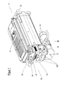
- FIG. 1 is an electric motor with a distributor box according to the invention 5 drawn on its second end face 13 in the oblique view. You can see the housing 1 of the electric motor, in which the electronics board 2 installed is, which is shown here by dashed lines, as it is not visible through the lid of the housing. At the first end face 11 of the housing 1, in FIG. 1 right, the shaft of the motor emerges as the output shaft 12.
- a distributor box 5 is arranged at the second end face 13 of the housing 1.
- a power connector 3 and a data connector 4 are housed in a common housing, which is integrally formed on the housing of the distributor box 5.
- the distribution box 5 is fixed with this housing on the housing 1, by a hinged latch which latches behind lugs on the outside of the distribution box 5.
- FIG. 1 On the outer surface of the distributor box 5 are in FIG. 1 including two data connectors 4 attached. They point radially away from the longitudinal axis of the housing 1. In the left to be seen data connector 4 an angled data mating connector 41 is inserted in the right to be seen data connector 4 is a straight data mating connector 41 is inserted.
- the illustrated data connection is very well suited for integration in an annular data line by a - not shown - data line from the left edge of the picture and the angled data mating connector 41, the first data connector 4, the distribution box 5 - where Electronics board 2 is looped, the second data connector 4 and the straight data counterpart 41 and further in a - not shown here - data line to the bottom right corner of FIG. 1 continues. There, the next drive can be inserted in the data line.
- FIG. 1 shown variant can also be configured with a very high degree of protection.
- FIG. 1 makes clear at first glance the clear advantage of this embodiment: In the axial direction of the motor, the entire connection set does not expand further, as it is predetermined by the overhanging part of the housing 1 with the electronics board 2 contained therein. The connecting cables thus do not extend the total length of the drive at all.
- FIG. 1 is also quickly clear at the data connector 4 on the visible longitudinal side that it can be installed in four mutually different positions by 90 °. This ensures that when inserting a - shown on the opposite, concealed longitudinal side - angled data mating connector 41, the outgoing cable can be aligned up or to the right or left or down.
- FIG. 2 is a distributor box according to the invention 5 drawn in an oblique image as a single part. Opposite the in FIG. 1 It is pivoted by 90 ° so that its in FIG. 1 hidden and the second end face 13 facing side is visible. This page is formed by a lid 53, which in FIG. 2 unscrewed and drawn off drawing, so that the view is free in the interior of the distribution box 5.
- the distributor box 5 in the embodiment of the FIG. 2 has a total of six openings 51.
- all openings 51 are of equal size. Therefore, they can optionally be equipped with a data connector 4 or with a power connector 3.
- FIG. 2 can be seen quickly that the connectors 3, 4 can be mounted in each case by 90 ° against each other pivoted positions. As a result, the orientation of the angled mating connector 31, 41 is specified.
- FIG. 2 the two power connectors 3 - of which only the left is visible - aligned so that the angular power mating connector 31 facing upward.
- the first data connector 4 is screwed. She wears - as well as in FIG. 1 - An angular data mating connector 41. On the opposite side of the distribution box 5, a data mating connector 41 is shown, which is straight.
- blind plug 52 can seal the openings 51 with a high degree of protection.
- FIG. 2 shown assembly of a distributor box 5 according to the invention is suitable for such cases in which the available installation space for the entire drive is limited to the underside.
- the stress on space at the second end in extension of the housing 13 is limited thanks to the angular power mating connector 31.
- the right side seen from the first end face 11 of the housing also limited by an angular data mating connector.
- the projection is larger by a straight mating connector 41.
- FIG. 2 are at the top of the distribution box 5 in a common housing two power connectors 3 for 24 V DC for supplying the electronic board 2 and arranged for 560 volts DC to supply an inverter for the power supply of the electric motor. Between these two power connectors 3, two data connectors 4 are placed in FIG. 2 can be recognized as small cylinders. These connectors (3,4) are in the embodiment of FIG. 2 but of a different shape than the other connectors (3,4) on the distributor box (5).
Landscapes
- Engineering & Computer Science (AREA)
- Power Engineering (AREA)
- Microelectronics & Electronic Packaging (AREA)
- Motor Or Generator Frames (AREA)
Abstract
Description
Die Erfindung bezieht sich auf einen Elektromotor mit einem Gehäuse, in dem wenigstens eine Elektronikplatine angeordnet ist, wobei aus der erster Stirnseite des Gehäuses die axial verlaufende Abtriebswelle herausragt und an der gegenüberliegenden, zweiten Stirnseite des Gehäuses eine elektrische Leistungssteckverbindung zur Versorgung des Elektromotors und der Elektronikplatine mit elektrischer Energie und wenigstens eine elektrische Datensteckverbindung zum Einlesen von Sollwerten in die Elektronikplatine und zum Auslesen von Istwerten und Speicherdaten und zum Austausch anderer Daten befestigt sind.The invention relates to an electric motor with a housing in which at least one electronic circuit board is arranged, protruding from the first end of the housing, the axially extending output shaft and on the opposite, second end face of the housing, an electrical power connector for supplying the electric motor and the electronic board are attached with electrical energy and at least one electrical data connector for reading setpoints in the electronic board and for reading actual values and memory data and for exchanging other data.
Im vergangenen halben Jahrhundert ist mit zunehmender Automatisierung von Maschinen und Geräten durch elektrische Antriebe deren Anzahl in einer einzelnen Maschine stark angestiegen. Auf aktuellem Stand der Technik sind z. B. Verpackungsmaschinen und Maschinen zum Abfüllen von Getränken mit Dutzenden von Elektromotoren ausgerüstet, deren Drehzahl oder deren Drehmoment oder deren Position elektronisch einstellbar ist. Dabei sind Steuerungen - auch "open loop" genannt - ebenso üblich wie Regelungen - auch "closed loop" oder Servoantrieb genannt.Over the past half-century, with increasing automation of machinery and equipment by electric drives, their number has risen sharply in a single machine. At the current state of the art z. B. packaging machines and machines for bottling drinks equipped with dozens of electric motors whose speed or torque or position is electronically adjustable. Controllers - also called "open loop" - are just as common as regulations - also called "closed loop" or servo drive.
Proportional zur Anzahl der Antriebe wuchsen auch der zugehörige Schaltschrank und die erforderlichen Kilometer an Kabeln. Der Aufwand für Planung, Fertigung und Inbetriebnahme aller notwendigen Verkabelungen wurde so groß, dass er ein nennenswerter Teil der Wertschöpfung der gesamten Maschine geworden ist.In proportion to the number of drives, the associated control cabinet and the required number of cables also grew. The cost of planning, manufacturing and commissioning of all necessary wiring has become so great that it has become a significant part of the value added of the entire machine.
Deshalb kam schon in den 70er Jahren des 20. Jhdts. die Idee auf, den Stromrichter aus dem Schaltschrank heraus und an den Motor zu verlegen. 1978 wurde unter
1986 wird unter
Auf aktuellem Stand der Technik werden hochwertige Servoregler samt der Auswertung der im Motor rotierenden Istwertgeber und der Ansteuerung und Datenausgabe über Bus-Systeme wie SERCOS, CAN und andere in das Gehäuse von Servomotoren integriert.State-of-the-art technology integrates high quality servocontrollers, including the evaluation of the actual value encoders rotating in the motor and the control and data output via bus systems such as SERCOS, CAN and others, into the housing of servomotors.
Die Erhöhung der Taktzahlen der Maschinen bei gleichzeitig wachsenden Anforderungen an die Genauigkeit und die Betriebssicherheit der Antriebe erfordern die laufende Rückmeldung von aktuellen Positions-Istwerten, Drehmoment-Istwerten und anderen Zustandsmeldungen. Ein dafür besonders gut geeignetes Bus-System wie SERCOS arbeitet bei einer ringförmigen Verkabelung aller Antriebe am effizientesten. Wenn eine solche Topologie in einer sternförmigen Verkabelung realisiert wird, wird durch die notwendige Hin- und Rückleitung die Verkabelung sehr aufwendig.The increase of the cycle numbers of the machines with simultaneously increasing demands on the accuracy and the operational safety of the drives require the continuous feedback of actual position actual values, torque actual values and other status messages. A particularly well-suited bus system such as SERCOS works most efficiently with an annular cabling of all drives. If such a topology is realized in a star-shaped wiring, the wiring is very complicated by the necessary forward and return line.
Zusätzlich müssen die Datenleitungen und die Leistungsversorgungen gut voneinander abgeschirmt werden, um Fehler durch Übersprechen von einem auf den anderen Leiter zu vermeiden.In addition, the data lines and the power supplies must be well shielded from each other to avoid crosstalk from one conductor to the other.
Die Aufgabe der Verkabelung wird dadurch weiter erschwert, dass die Motoren für einen möglichst effizienten Betrieb mit einer weit höheren Spannung versorgt werden müssen als die Elektronik. Dafür geeignete Kabel sind also relativ komplex und voluminös und deshalb schwer zu verlegen.The task of cabling is made more difficult by the fact that the motors for a most efficient operation with a much higher Voltage must be supplied as the electronics. Suitable cables are therefore relatively complex and voluminous and therefore difficult to install.
Wenn zur Reduzierung der Gesamtlänge der Kabel eine ringförmige Struktur aufgebaut werden soll, die dann auch noch an jedem Motor zwecks Reduzierung der Montage- und Wartungszeiten steckbar sein soll, ergeben sich als weitere Probleme, dass an jedem Motor wenigstens vier Steckverbindungen nötig werden, nämlich mindestens zwei für das Herein- und das Herausführen der Leistungsverkabelung und wenigstens zwei weitere für den Datenaustausch. Zusätzlich muss ein Raum für das elektrische Anbinden des Motors und der Elektronikplatine geschaffen werden.If an annular structure is to be built to reduce the total length of the cable, which is then also to be plugged at each engine in order to reduce the assembly and maintenance times, arise as further problems that at least four connectors are required on each engine, namely at least two for the in and out of the power cabling and at least two more for the data exchange. In addition, a space for the electrical connection of the motor and the electronic board must be created.
Ein derartiger Aufbau ist insbesondere bei kleinen Motoren - unterhalb eines Nenndrehmomentes von rund 10 Nm so voluminös und sperrig, dass sein Raumbedarf fast dem des Motors entspricht. Der erforderliche Einbauraum für die Steckverbindungen kann also in ungünstigen Fällen so groß werden, dass der Einbauraum für den gesamten Antrieb doppelt so groß wie für den Motor selbst ist.Such a construction is so voluminous and bulky, especially in small engines - below a nominal torque of around 10 Nm, that its space requirement corresponds almost to that of the engine. The required installation space for the connectors can be so great in unfavorable cases that the installation space for the entire drive is twice as large as for the engine itself.
Eine zusätzliche Schwierigkeit ergibt sich bei sehr dicht beieinander angeordneten Motoren. Dann darf die Verkabelung nicht radial über den Querschnitt des Motors hinausragen, denn dort würde sie mit den Kabeln und den Steckverbindungen benachbarter Motore kollidieren.An additional difficulty arises in very closely spaced engines. Then the wiring must not protrude radially beyond the cross-section of the motor, because there it would collide with the cables and the connectors of adjacent motors.
In derselben Maschine kann es jedoch auch Einbauräume geben, die einen in axialer Richtung besonders kurzen Antrieb erfordern. In dieser Situation sollen die Anschlüsse in axialer Richtung möglichst wenig über den Motor hinausragen. Stattdessen ist eine radiale Ausrichtung zu bevorzugen, also genau entgegensetzt zu der Forderung im vorherigen Absatz.In the same machine, however, there may also be installation spaces which require a particularly short drive in the axial direction. In this situation, the connections in the axial direction should protrude as little as possible over the engine. Instead, there is a radial orientation to be preferred, in contrast to the requirement in the previous paragraph.
Auf diesem Hintergrund hat sich die Erfindung die Aufgabe gestellt, eine einfache standardisierte Vorrichtung zu entwickeln, mit der mehrere Elektromotoren mit integrierter Elektronik unter Verwendung von bekannten Standardkomponenten relativ schnell und relativ kostengünstig in möglichst vielen verschiedenen Einbausituationen steckbar miteinander verkabelt werden können, und zwar bei sehr unterschiedlichen Einbausituationen und Einbauräumen mit einer Begrenzung in axialer Richtung oder in mehreren radialen Richtungen.Against this background, the invention has set itself the task of developing a simple standardized device with which several electric motors with integrated electronics using known standard components can be plugged relatively quickly and relatively inexpensively in as many different installation situations with each other, and at very different installation situations and installation spaces with a limitation in the axial direction or in several radial directions.
Als Lösung lehrt die Erfindung, dass auf die Leistungssteckverbindung und auf die Datensteckverbindung eine Verteilerbox aufgesteckt werden kann, deren Abmessungen in radialer Richtung im wesentlichen kleiner sind als der Querschnitt des Gehäuses und die zusätzlich zu den Steckverbindungen zwischen Elektromotor, Elektronikplatine und Verteilerbox wenigstens vier Öffnungen zum Einbau von weiteren Steckverbindungen aufweist, von denen wenigstens zwei in axiale Richtung des Gehäuses weisen und wenigstens zwei radial ausgerichtet sind und innerhalb der Verteilerbox elektrische Verbindungen zwischen den Steckverbindungen herstellbar sind.As a solution, the invention teaches that a distribution box can be plugged into the power connector and the data connector whose dimensions in the radial direction are substantially smaller than the cross section of the housing and in addition to the connectors between the electric motor, electronic board and distribution box at least four openings Installation of further plug connections, of which at least two point in the axial direction of the housing and at least two are radially aligned and within the distributor box electrical connections between the connectors can be produced.
Das herausragende Merkmal der Erfindung ist also die Verteilerbox. Sie ermöglicht eine universelle Anpassung der Verkabelung eines Elektromotors mit integrierter Elektronik an die verschiedensten räumlichen Bedingungen beim Einbau in eine Maschine. Und zwar insbesondere dann, wenn standardisierte Kabelsätze verwendet werden, bei denen z.B. nur zwischen einem geraden und einem gewinkelten Stecker für die Datenverbindung und zwischen einer geraden und einer gewinkelten Dose für die Leistungsverbindung gewählt werden kann und der maximale Krümmungsradius relativ groß ist.The outstanding feature of the invention is thus the distributor box. It enables a universal adaptation of the cabling of an electric motor with integrated electronics to a wide variety of spatial conditions when installed in a machine. In particular, if standardized cable sets are used, in which eg only between a straight and angled connector for the data connection and between a straight and an angled box for the power connection can be selected and the maximum radius of curvature is relatively large.
Ein wichtiges bauliches Merkmal der Verteilerbox selber ist, dass ihre Abmessungen in radialer Richtung im Wesentlichen gleich groß oder kleiner sind als der Querschnitt des Gehäuses vom Motor, so dass sie den Antrieb in radialer Richtung nicht vergrößern.An important structural feature of the distribution box itself is that its dimensions in the radial direction are substantially equal to or smaller than the cross section of the housing of the engine, so that they do not increase the drive in the radial direction.
Ein weiteres, grundsätzliches Merkmal jeder Verteilerbox ist es, Öffnungen zum Einbau von Steckverbindungen sowohl in radialer, als auch in axialer Richtung zu bieten. Deshalb kann die Verteilerbox z.B. dann eingesetzt werden, wenn der gesamte Motor einschließlich Verkabelung in axialer Richtung möglichst kurz sein soll, aber sich radial ausdehnen darf.Another fundamental feature of each distribution box is to provide openings for the installation of connectors both in the radial and in the axial direction. Therefore, the distribution box can e.g. be used when the entire engine including wiring in the axial direction should be as short as possible, but allowed to expand radially.
Die Verteilerbox ist auch dann sinnvoll, wenn der Antrieb insgesamt möglichst schlank sein muss - z.B. weil er parallel zu zahlreichen weiteren Motoren angeordnet ist - aber in seiner axialen Ausrichtung noch freien Raum vorfindet.The distributor box is also useful if the drive as a whole must be as slim as possible - e.g. because it is arranged parallel to numerous other engines - but still finds free space in its axial orientation.
Die Verteilerbox ermöglicht eine Anpassung der Verkabelung auch dann, wenn der Motor ganz nahe an einer Fläche - wie z.B. einer Seitenwand montiert werden muss und in diese Richtung kein Kabel verlegt werden kann.The distribution box allows the wiring to be adjusted even if the motor is located very close to a surface, such as a surface. a side wall must be mounted and no cable can be laid in this direction.
Die Verteilerbox ist sogar dann hilfreich, wenn der Motor mit seiner ersten Stirnseite in einer Platte montiert ist und die Verkabelung möglichst direkt auf die Rückseite dieser Platte geführt und dort weiter verlegt werden soll.The distributor box is helpful even when the motor is mounted with its first end face in a plate and the wiring should be routed as directly as possible to the back of this plate and laid there further.
Um eine ausreichende Variabilität erreichen zu können, benötigt eine erfindungsgemäße Verteilerbox im einfachsten Fall neben den Anschlüssen zum Motor noch vier Öffnungen, in die Steckverbindungen zum Übertragen von elektrischer Leistung oder Steckverbindungen zur Übertragung von Daten eingesetzt werden können. Die Leistungsverbindungen übertragen Ströme zur Versorgung eines Umrichters zur Drehzahl- oder Drehmomentregelung oder Steuerung eines Motors, sowie zur Versorgung der Elektronik selbst. Aktuell übliche Spannungen zur Versorgung der Umrichter für die Motoren sind z.B. 250 bis 700 Volt Gleichstrom und zur Versorgung der Elektronik 24 Volt Gleichstrom.In order to achieve sufficient variability, a distributor box according to the invention in the simplest case next to the connections to the engine still requires four openings, can be used in the connectors for transmitting electrical power or connectors for the transmission of data. The power connections transmit currents to power an inverter for speed or torque control or control of a motor, as well as to power the electronics themselves. Currently common voltages for powering the inverters for the motors are e.g. 250 to 700 volts DC and to supply the electronics 24 volts DC.
Über die Datenstecker werden Sollwerte, wie Positionen, Drehzahlen, Drehmomente, Höchstwerte, Mindestwerte oder andere Befehle oder Parameter an die Elektronikplatine im Gehäuse gesendet und von dort auch Daten empfangen, wie z.B. Istwerte von Positionen, Drehzahlen, Drehmomenten oder gespeicherte Daten, z.B. aus einem Datenrekorder über zurückliegende Ereignisse oder über die Parametrierung eines Reglers in der Elektronikplatine im Motor. Diese Daten werden in aller Regel in einer zentralen Steuerung generiert bzw. verarbeitet.Via the data plugs, setpoints such as positions, speeds, torques, maximum values, minimum values, or other commands or parameters are sent to the electronic board in the housing and receive data therefrom, e.g. Actual values of positions, speeds, torques or stored data, e.g. from a data recorder via past events or via the parameterization of a controller in the electronic board in the motor. This data is usually generated or processed in a central controller.
Die erfinderische Verteilerbox ist für eine Montage an der abtriebsfernen Stirnseite des Motorgehäuses vorgesehen, die also der anderen Stirnseite mit der Abtriebswelle gegenüberliegt. Von dort aus können sich die Anschlüsse wahlweise in radialer oder in axialer Richtung erstrecken.The inventive distributor box is provided for mounting on the output side of the motor housing which is remote from the output, which thus lies opposite the other end face with the output shaft. From there, the connections can optionally extend in the radial or in the axial direction.
Weil die Daten in der Praxis der Wirtschaftlichkeit halber zumeist in einem Kabel übertragen werden, das vom Leistungskabel getrennt verläuft, werden in der einfachsten Ausführungsform einer erfindungsgemäßen Verteilerbox auch wenigstens zwei Öffnungen in radialer und zwei Öffnungen in axialer Richtung vorgesehen.Because the data in practice for the sake of economy mostly in a cable are transmitted, which runs separately from the power cable, in the simplest embodiment of an inventive Distributor also provided at least two openings in the radial and two openings in the axial direction.
Die beiden axial ausgerichteten Öffnungen werden im allgemeinsten Fall nebeneinander in der gleichen Fläche angeordnet sein. Das ist auch für die beiden radial ausgerichteten Anschlüsse möglich. In der Praxis wird es jedoch bevorzugt werden, dass die beiden radial ausgerichteten Öffnungen in verschiedene Richtungen weisen, insbesondere in genau entgegen gesetzte Richtungen. Vorteilhaft ist es, die beiden waagerecht abgehenden Öffnungen so gegeneinander zu versetzen, dass die Stecker zweier nah benachbarter Motoren nicht miteinander kollidieren. Dazu bietet die Stirnkante der Verteilerbox auch ausreichend viele verschiedene Möglichkeiten.The two axially aligned openings will, in the most general case, be arranged side by side in the same area. This is also possible for the two radially aligned connections. In practice, however, it will be preferred that the two radially aligned openings face in different directions, especially in exactly opposite directions. It is advantageous to offset the two horizontally outgoing openings against each other so that the plug of two closely adjacent motors do not collide with each other. In addition, the front edge of the distributor box also offers a sufficient number of different possibilities.
Für die Mindestgröße einer erfindungsgemäßen Verteilerbox ergibt sich ein erstes Kriterium daraus, dass die Stecker für die Datensteckverbindung in aller Regel eine Mindestgröße nicht unterschreiten können. Daraus ergibt sich eine Mindestgröße für den zur Befestigung erforderlichen Flansch. Das zweite Kriterium für die Mindestgröße ist die Größe der Leistungssteckverbindung.For the minimum size of a distributor box according to the invention, a first criterion results from the fact that the plug for the data connector can usually not fall below a minimum size. This results in a minimum size for the flange required for attachment. The second criterion for the minimum size is the size of the power connector.
In der Praxis wird bei den kleineren Motoren der Flansch für die Leistungssteckverbindung meist die gleiche Größe wie der Flansch für die Datensteckverbindung haben. Eine nach diesen Kriterien festgelegte Mindestgröße kann natürlich auch für Elektromotoren mit größerem Querschnitt verwendet werden, sofern in der Leistungssteckverbindung dann noch ein ausreichender Leiterquerschnitt untergebracht werden kann.In practice, the flange for the power connector will usually be the same size as the flange for the data connector in the smaller motors. A specified according to these criteria minimum size can of course be used for electric motors with a larger cross-section, if in the power connector then a sufficient conductor cross-section can be accommodated.
Es ist deshalb in der Praxis absehbar, dass auch eine größere Motorfamilie mit einer relativ geringen Anzahl von verschiedenen Größen einer Verteilerbox abgedeckt werden kannIt is therefore foreseeable in practice that even a larger engine family can be covered with a relatively small number of different sizes of a distribution box
In der Praxis wird es also relativ zahlreiche Motore geben, bei denen der Befestigungsflansch für die Leistungssteckverbindung die gleiche Größe wie der Befestigungsflansches für die Datensteckverbindung hat. In diesen Fällen ist es sinnvoll, dass in die Öffnungen der Verteilerbox wahlweise eine Leistungssteckverbindung oder eine Datensteckverbindung eingebaut werden kann. Das ist insbesondere dann sehr einfach, wenn die Befestigungsflansche der Leistungssteckverbindung und der Datensteckverbindung nach außen hin identisch sind. Dann sind auch die Öffnungen und die Vorrichtung zum Einbau der Steckverbinder, wie z.B. zusätzliche Schraublöcher identisch.In practice, therefore, there will be relatively many motors in which the mounting flange for the power connector has the same size as the mounting flange for the data connector. In these cases, it makes sense that in the openings of the distribution box either a power connector or a data connector can be installed. This is particularly easy if the mounting flanges of the power connector and the data connector are identical to the outside. Then, the openings and the device for installing the connectors, such as. additional screw holes identical.
Alternativ ist jedoch auch ein Einbau von verschiedenen Steckverbindungen in einer Öffnung möglich, wenn für beide Typen entsprechende, zumindest teilweise, komplementäre Einbauvorrichtungen geschaffen sind. Zur Überbrückung von Größenunterschieden zwischen den kleinen Flanschen von Datensteckern und den großen Flanschen von Leistungssteckern sind z.B. Zungen denkbar, die in die Öffnung hineinragen und die kleine Flansche tragen und die vor dem Einbau von großen Flanschen zur Seite gebogen oder abgekniffen werden.Alternatively, however, an installation of different connectors in an opening is possible if for both types corresponding, at least partially, complementary mounting devices are provided. To bridge the size differences between the small flanges of data connectors and the large flanges of power connectors, e.g. Tongue conceivable that protrude into the opening and carry the small flanges and bent or flared before installation of large flanges to the side.
Eine Anpassung an unterschiedlich große Typen von Steckern ist auch dadurch möglich, dass die Öffnung eine längliche Form aufweist und dahinein passende, große Stecker mit Kontaktstiften in Reihe eingebaut werden können. In diese länglich geformten, großen Öffnungen werden alternativ kleine, etwa quadratische Steckverbindungen quer zur Längsachse der Öffnung eingesetzt, so dass sie nur einen Teil der Öffnung ausfüllen, aber trotzdem an den gegenüberliegenden Kanten der Öffnungen mechanisch befestigt werden können, z.B. durch Verschrauben.An adaptation to different sized types of plugs is also possible in that the opening has an elongated shape and can be installed in matching large plug with pins in series. In these elongated, large openings alternatively small, approximately square connectors are inserted transversely to the longitudinal axis of the opening, so that they only fill a part of the opening, but can still be mechanically attached to the opposite edges of the openings, for example by screwing.
In den beiden vorgenannten und in anderen Fällen, bei denen Teile der Öffnung durch die Steckverbindung nicht abgedeckt werden, kann eine zusätzliche Abdeckung zum Verschließen der Öffnungen montiert werden. Dadurch kann eine entsprechend hohe Schutzart des gesamten Antriebes erreicht werden.In the above two and in other cases, where parts of the opening are not covered by the connector, an additional cover for closing the openings can be mounted. As a result, a correspondingly high degree of protection of the entire drive can be achieved.
Im Prinzip ist bei einer erfindungsgemäßen Verteilerbox die Anzahl der Öffnungen zum Einbau von Steckverbindungen nicht begrenzt. Je größer die Anzahl der Öffnungen ist, desto größer ist die Möglichkeit, eine bestimmte, passende Richtung für eine Steckverbindung auswählen zu können. Nicht benutzte Öffnungen können dann durch Blindstopfen verschlossen werden.In principle, in a distributor box according to the invention, the number of openings for the installation of connectors is not limited. The larger the number of openings, the greater the possibility of being able to select a specific, suitable direction for a plug connection. Unused openings can then be closed by blind plugs.
Bei der Anwendung wird eine besonders interessante Variante einer erfindungsgemäßen Verteilerbox sechs Öffnungen zuzüglich der Anschlüsse an den Motor aufweisen. In praktischen Versuchen hat sich von den verschiedenen, denkbaren Varianten mit sechs Öffnungen eine Ausführung als besonders vielfältig einsetzbar herausgestellt, die zwei Öffnungen in axialer Richtung und weitere Öffnungen in verschiedene radiale Richtungen aufweist. Eine derartige Variante mit Öffnungen in drei verschiedenen, radialen Richtungen wird hier als Ausführungsbeispiel grafisch dargestellt und textlich beschrieben.In use, a particularly interesting variant of a distributor box according to the invention will have six openings plus the connections to the motor. In practical experiments, of the various conceivable variants with six openings, an embodiment has proven to be particularly versatile, having two openings in the axial direction and further openings in different radial directions. Such a variant with openings in three different radial directions is shown graphically here as an embodiment and described textually.
Zusätzliche Varianten für die Ausrichtung der Steckverbindungen ergeben sich beim Einbau in die Öffnung der Verteilerbox durch Verschwenken der Steckverbindung um ihre Längsachse. Eine mit üblichen Steckern leicht zu verwirklichende und in den hier anliegendenAdditional variants for the alignment of the connectors arise when installed in the opening of the distributor box by pivoting the connector about its longitudinal axis. One with usual plugs easily to be realized and in the here attached
Figuren dargestellte Variante ist eine etwa quadratische Öffnung mit vier gleichmäßig darum herum angeordneten Gewindesacklöchern. In diese Öffnung kann z.B. die Dose einer Steckverbindung jeweils um 90 ° verschwenkt eingesetzt werden. Wenn in diese Steckverbindung ein Winkelstecker eingesetzt wird, so ist damit eine Änderung der Abgangsrichtung in vier Stufen möglich.Figures shown variant is an approximately square opening with four evenly arranged around threaded blind holes. In this opening can e.g. the can of a connector can be used pivoted by 90 °. If an angle plug is used in this plug connection, it is possible to change the outgoing direction in four stages.
Es ist natürlich auch eine feinere Auflösung der Winkelausrichtung der Stecker als nur 90° möglich. Wenn z.B. der Stecker an seiner Außenfläche eine Kerbverzahnung aufweist, die in dazu komplementären Nuten in den Öffnungen hineinpasst, kann ein Steckverbinder mit einer ziemlich feinen Abstufung seiner Verschwenkung gegenüber der Verteilerbox montiert werden.Of course, it is also possible a finer resolution of the angular orientation of the connector as only 90 °. If e.g. the plug has serration on its outer surface which fits into complementary grooves in the apertures, a connector with a fairly fine gradation of its pivoting relative to the splitter box can be mounted.
Ein im Querschnitt kreisförmiger Stecker kann beim Einbau stufenlos verschwenkt werden. Er sollte dann aber gegen ein unbeabsichtigtes Verschwenken gesichert werden, z.B. durch eine zusätzliche Klemmverschraubung.A cross-sectionally circular plug can be pivoted continuously during installation. It should then be secured against inadvertent pivoting, e.g. through an additional compression fitting.
Um die Variabilität bei der Ausrichtung der Stecker noch weiter zu erhöhen schlägt die Erfindung winkelige Gegenstecker vor, die entweder in sich verschwenkbar sind oder die in eine verschwenkbare Dose einsteckbar sind. Eine derartige Verschwenkbarkeit ist z.B. durch im Gehäuse des Gegensteckers verschwenkbare Steckkontakten und deren flexible Verbindungen zum Anschlusskabel möglich. Die Verschwenkbarkeit kann entweder generell möglich sein oder nur nach Lockern einer mechanischen Befestigung, wie z.B. einer Überwurfmutter.In order to increase the variability in the alignment of the plug still further, the invention proposes angled mating connector, which are either in itself pivotable or which can be inserted into a pivotable box. Such pivotability is e.g. by in the housing of the mating connector pivotable plug contacts and their flexible connections to the connection cable possible. The pivotability can either be generally possible or only after loosening of a mechanical attachment, such as e.g. a union nut.
Wenn der Stecker nicht senkrecht zur Fläche der Öffnung ausgerichtet ist, sondern schräg, dann wird sich durch eine Verschwenkung des Steckers gegenüber der Verteilerbox auch die Ausrichtung des Steckers entsprechend ändern.If the plug is not perpendicular to the surface of the opening, but obliquely, then it will be by a pivoting also change the orientation of the plug relative to the distributor box.
In einer besonders universell nutzbaren Ausführungsform einer erfindungsgemäßen Verteilerbox sind an der zweiten Stirnseite des Gehäuses vom Elektromotor die gleichen Leistungssteckverbinder und die gleichen Datensteckverbinder angebracht, die auch in die Öffnungen der erfindungsgemäßen Verteilerbox montiert werden. Dann kann in einer Maschine mit mehreren Motoren alternativ ein Motor auch ohne eine Verteilerbox direkt mit einem standardisierten Anschlusskabel verdrahtet werden, das auch für den Anschluss an eine Verteilerbox geeignet ist.In a particularly universally usable embodiment of a distributor box according to the invention the same power connectors and the same data connectors are mounted on the second end face of the housing from the electric motor, which are also mounted in the openings of the distributor box according to the invention. Then, in a multi-motor machine, alternatively, a motor can be wired directly to a standard connection cable even without a distribution box, which is also suitable for connection to a distribution box.
Auf diese Weise können mehrere Motoren sternförmig an eine zentrale Elektronikbaugruppe oder einen zentralen Anschlusskasten angeschlossen werden. Als Anschlusskasten kann eine erfindungsgemäße Verteilerbox auch ohne Motor genutzt werden.In this way, several motors can be connected in a star shape to a central electronic module or a central terminal box. As a connection box, a distributor box according to the invention can also be used without a motor.
In einen mit Standardsteckern bestückten Motor kann ohne jeden weiteren Umbau anstelle eines direkten Anschlusses eine erfindungsgemäße Verteilerbox eingesteckt werden, mit der dieser Motor dann in eine serielle oder kettenförmige Verkabelung eingebunden wird.In a stocked with standard plug motor can be plugged without any further conversion instead of a direct connection, a distributor box according to the invention, with which this motor is then integrated into a serial or chain-shaped wiring.
In einer anderen Ausführungsform sind die Leistungssteckverbindung und die Datensteckverbindung an der zweiten Stirnseite des Motorgehäuses in einer gemeinsamen Einhausung zusammengefasst. Diese Konfiguration wird auch als "Hybridstecker" bezeichnet. Die Einhausung kann für eine besonders stabile Befestigung der Verteilerbox - z.B. mit einer klappbaren Sicherungskralle - genutzt werden.In another embodiment, the power connector and the data connector are combined on the second end face of the motor housing in a common housing. This configuration is also referred to as a "hybrid plug". The housing can be used for a particularly stable attachment of the distribution box - eg with a folding safety claw.
Auf aktuellem Stand der Technik sind Hybridkabel bekannt, die sowohl zur Leistungsversorgung eines Motors als auch zur Übertragung von Daten in die Elektronik im Motor als auch zum Auslesen von Daten aus dieser Elektronik nutzbar sind. Da derartige Kabel relativ aufwendig sind, werden sie in der Praxis nur an solchen Stellen eingesetzt, wo die Raumnot besonders hoch ist.At the current state of the art, hybrid cables are known which can be used both to supply power to a motor and to transmit data to the electronics in the motor as well as to read out data from this electronics. Since such cables are relatively expensive, they are used in practice only in places where the lack of space is particularly high.
Die erfindungsgemäße Verteilerbox ermöglicht innerhalb der Verdrahtung einer Maschine mit mehreren Motoren den Wechsel von den teuren Hybridkabeln auf kostengünstigere, getrennte und parallel verlegte Kabel zur Leistungsversorgung und zur Datenübertragung. Dafür wird in die Öffnung einer erfindungsgemäßen Verteilerbox eine passende Steckverbindung für ein Hybridkabel eingesetzt. Innerhalb der Verteilerbox wird diese Hybridsteckverbindung mit einer Leistungssteckverbindung sowie mit einer Datensteckverbindung verdrahtet. Zusätzlich wird auch eine Verbindung zu dem Leistungsanschluss und zum Datenanschluss des jeweiligen Motors hergestellt. An einer derart konfigurierten Verteilerbox kann eine serielle Verdrahtung von Hybridkabeln auf getrennte Verkabelung und umgekehrt wechseln.The distributor box according to the invention makes it possible, within the wiring of a machine with several motors, to switch from the expensive hybrid cables to more cost-effective, separate and parallel cables for power supply and data transmission. For a suitable connector for a hybrid cable is used in the opening of a distribution box according to the invention. Within the distribution box, this hybrid connector is wired to a power connector as well as a data connector. In addition, a connection is also made to the power connection and to the data connection of the respective motor. On a distribution box configured in this way, a serial wiring of hybrid cables can change to separate cabling and vice versa.
In einer weiteren Ausführungsvariante wird auf wenigstens eine Öffnung der Verteilerbox ein Winkeladapter in Form eines zweiseitig offenen Hohlkörpers aufgesetzt. Er ist ein Zwischenstück zwischen der Öffnung in der Verteilerbox und einer Steckverbindung. Dieser Adapter ist an seiner ersten, offenen Seite komplementär zu der Öffnung geformt, auf welcher der Hohlkörper aufgesetzt ist. Mit dieser Seite kann der Winkeladapter also wie eine Steckverbindung in der Öffnung der Verteilerbox befestigt werden. Seine zweite, offene Seite ist identisch zu der Öffnung geformt, auf der der Hohlkörper aufgesetzt ist. Deshalb kann in diese zweite offene Seite eine Steckverbindung befestigt werden.In a further embodiment, an angle adapter in the form of a hollow body open on two sides is placed on at least one opening of the distributor box. It is an intermediate piece between the opening in the distributor box and a plug connection. This adapter is formed on its first, open side complementary to the opening on which the hollow body is placed. With this side, the angle adapter can thus be fixed like a plug-in connection in the opening of the distributor box. Its second, open side is shaped identically to the opening on which the hollow body is placed is. Therefore, in this second open side a connector can be attached.
Die eigentliche Funktion des Winkeladapters ist es, die Ausrichtung der Ebene einer Öffnung in der Verteilerbox abzuändern. Wenn die beiden offenen Seiten des Winkeladapters einen Winkel von 90 Grad zueinander einnehmen, wird dadurch auch die Steckverbindung um 90 Grad abgewinkelt. Ein derartiger Winkeladapter kann natürlich auch für beliebige andere Winkel erstellt werden.The actual function of the angle adapter is to change the orientation of the plane of an opening in the junction box. If the two open sides of the angle adapter make an angle of 90 degrees to each other, this will also cause the connector to be angled 90 degrees. Such an angle adapter can of course be created for any other angle.
Innerhalb einer erfindungsgemäßen Verteilerbox kann die für eine serielle Verkabelung ggf. erforderliche "T-Verbindung" unabhängig von den jeweils gewählten Kabelarten hergestellt werden: Die Steckverbindungen für die Leistung und für die Datenübertragung des Motors werden jeweils mit beiden Steckverbindungen in der Verteilerbox verdrahtet.Within a distributor box according to the invention, the "T connection" possibly required for serial cabling can be produced independently of the cable types selected in each case: The plug connections for the power and for the data transmission of the motor are each wired with two plug connections in the distributor box.
Es kann innerhalb einer erfindungsgemäßen Verteilerbox frei gewählt werden, ob nur die Leistungsverbindung oder nur die Datenverbindung T-förmig hergestellt werden soll, oder beide.It can be freely selected within a distributor box according to the invention, whether only the power connection or only the data connection to be made T-shaped, or both.
Für den Aufbau einer seriellen Verdrahtung zur Datenübertragung nach dem SERCOS-Prinzip wird eine erste Datensteckverbindung in der Verteilerbox mit einer ersten Datensteckverbindung auf der Elektronikplatine verbunden und eine zweite Datensteckverbindung in der Verteilerbox mit einer zweiten Datensteckverbindung auf der Elektronikplatine. Für eine CAN-Verbindung wird innerhalb der Verteilerbox eine T-förmige elektrische Verbindung zwischen den beiden "externen" Datensteckverbindungen und der Datensteckverbindung zur Elektronikplatine erstellt.For the construction of a serial wiring for data transmission according to the SERCOS principle, a first data plug connection in the distribution box is connected to a first data plug connection on the electronic board and a second data plug connection in the distribution box to a second data plug connection on the electronic board. For a CAN connection, a T-shaped electrical connection is created within the distributor box between the two "external" data connectors and the data connector to the electronic board.
Innerhalb der Verteilerbox können also z.B. drei T-förmig verdrahte Anschlüsse für die Datenverbindung mit nur zwei verdrahteten Anschlüssen für die Leistungsversorgung kombiniert werden. Oder umgekehrt. Auf diese Weise ist bei einem Mehrmotorenantrieb einer Maschine die Kombination einer ringförmigen Leistungsversorgung mit einer sternförmigen Datenübertragung oder alternativ eine ringförmige Datenübertragung mit einer sternförmigen Energieversorgung möglich.Within the distribution box, e.g. three T-shaped connectors for data connection can be combined with only two wired connectors for power supply. Or the other way around. In this way, in a multi-motor drive of a machine, the combination of an annular power supply with a star-shaped data transmission or alternatively an annular data transmission with a star-shaped power supply is possible.
Dank der erfindungsgemäßen Verteilerbox kann also die Verkabelung einer Maschine mit zahlreichen Antrieben in einer ringförmigen Topologie - auch Daisy-Chain genannt - oder in einer sternförmigen Topologie oder in einer baumartigen Struktur frei gewählt oder in frei wählbaren Mischformen verwirklicht werden.Thanks to the distributor box according to the invention, therefore, the wiring of a machine with numerous drives in an annular topology - also called daisy chain - or in a star-shaped topology or in a tree-like structure can be chosen freely or in freely selectable hybrid forms.
Die eleganteste Art der Ermittlung der Verkabelungsstruktur ist eine Ausarbeitung bereits bei der Konstruktion der Maschine. Alternativ ist aber auch eine experimentelle Ermittlung durch Versuch an einer praktisch existierenden oder umzubauenden Maschine möglich. In jedem Fall werden in einem ersten Schritt die Elektromotore an der Maschine platziert. In einem zweiten Schritt wird dann geprüft, ob der jeweilige Motor im Bereich seiner zweiten Stirnseite in der Maschine einen größeren Freiraum in axialer oder einen größeren Freiraum in radialer Richtung hat, oder ob der verfügbare Freiraum in keiner der beiden Richtungen sehr groß ist.The most elegant way of determining the cabling structure is to work out the design of the machine. Alternatively, however, an experimental determination by trial on a practically existing or to be converted machine is possible. In any case, in a first step, the electric motors are placed on the machine. In a second step, it is then checked whether the respective engine in the region of its second end face in the machine has a larger clearance in the axial direction or a larger clearance in the radial direction, or whether the available clearance in either direction is very large.
Dann können in einem dritten Schritt z.B. bei Motoren mit axialem Freiraum in die zwei axial ausgerichteten Öffnungen der Verteilerbox je eine Leistungssteckverbindung mit einem geraden Leistungsgegenstecker eingebaut werden und zwei radial ausgerichtete Öffnungen der Verteilerbox je eine Datensteckverbindung mit je einem winkeligen Datenstecker eingebaut werden.Then in a third step, for example, in motors with axial clearance in the two axially aligned openings of the distribution box per a power connector with a straight power mating connector can be installed and two radially aligned openings The distributor box each a data connector with one angular data plug are installed.
Für die Motoren, die in radialer Richtung einen Freiraum aufweisen, werden in einem vierten Schritt z.B. nur in radial ausgerichtete Öffnungen der Verteilerbox Steckverbindungen mit geraden Gegensteckern eingebaut und in axial ausgerichtete Öffnungen grundsätzlich nur Steckverbindungen mit winkeligen Gegensteckern eingesetzt.For the motors which have a free space in the radial direction, in a fourth step e.g. installed only in radially aligned openings of the distribution box connectors with straight mating connectors and used in axially aligned openings basically only connectors with angled mating connectors.
Insbesondere bei Motoren, die fast gar keinen Freiraum an ihrer zweiten Stirnseite nutzen können, werden ohne Einfügung einer erfindungsgemäßen Anschlussbox die Anschlusskabel direkt an den Motor angeschlossen und mit einem zentralen Anschlusskasten oder einer zentralen Elektronikbaugruppe oder einer erfindungsgemäßen Verteilerbox an einem anderen Motor verkabelt.In particular, in engines that can use almost no clearance on their second face, the connection cables are connected directly to the engine without insertion of a junction box according to the invention and wired to a central terminal box or a central electronic module or distributor box according to the invention on another motor.
Im Folgenden sollen weitere Einzelheiten und Merkmale der Erfindung anhand eines Beispiels näher erläutert werden. Dieses soll die Erfindung jedoch nicht einschränken, sondern nur erläutern. Es zeigt in schematischer Darstellung:
- Figur 1
- Schrägbild eines Elektromotors mit montierter Verteilerbox
Figur 2- Verteilerbox als Einzelteil mit zwei Leistungssteckverbindungen und zwei Datensteckverbindungen
- FIG. 1
- Oblique view of an electric motor with mounted distribution box
- FIG. 2
- Distributor box as an item with two power connectors and two data connectors
In
An der zweiten Stirnseite 13 des Gehäuses 1 ist eine erfindungsgemäße Verteilerbox 5 angeordnet. Auf der Oberseite der Verteilerbox 5 sind eine Leistungssteckverbindung 3 und eine Datensteckverbindung 4 in einer gemeinsamen Einhausung untergebracht, die an das Gehäuse der Verteilerbox 5 angeformt ist. Im Ausführungsbeispiel der
Auf der Außenfläche der Verteilerbox 5 sind in
Anhand der
An der Unterseite der Verteilerbox 5 sind zwei Leistungssteckverbindungen 3 mit darin eingesteckten Leistungsgegensteckern 31 zu sehen. Beide Leistungsgegenstecker 31 sind abgewinkelt, wodurch die Ausladung des kompletten Antriebes in radialer Richtung begrenzt wird.On the underside of the
An der nach links weisenden großen Außenfläche der Verteilerbox 5 sind zwei Blindstopfen 52 zu sehen, die die - nur in
Im linken Drittel der
In
In
Dadurch wird sofort sichtbar, dass die Verteilerbox 5 in der Ausführungsform der
In
In die Öffnung 51 an der rechten Seite der Verteilerbox 5 ist die erste Datensteckverbindung 4 eingeschraubt. Sie trägt - ebenso wie in
Die in dieser Variante ungenutzten beiden Öffnungen 51, die nach unten weisen, sind jeweils mit einem Blindstopfen 52 verschlossen. In
Die in
In
Trotzdem wird es nachvollziehbar, dass es alternativ auch möglich ist, den Elektromotor mit der darin integrierten Elektronikplatine (2) unter Weglassen der Verteilerbox (5) direkt an ein Hybridkabel mit Leistungsversorgungen und mit Datenübertragung anzuschließen. Ein zur dargestellten Verteilerbox (5) passender Motor mit integrierter Elektronik muss dann an das "Hybridkabel mit einem "Hybridstrecker" angeschlossen werden, der dem in
- 11
- Gehäuse des ElektromotorsHousing of the electric motor
- 1111
- erste Stirnseite des Gehäuses 1first end face of the housing 1
- 1212
- Abtriebswelle des ElektromotorsOutput shaft of the electric motor
- 1313
- zweite Stirnseite des Gehäuses 1second end face of the housing 1
- 22
- Elektronikplatine im Gehäuse 1Electronics board in the housing 1
- 33
- Leistungssteckverbindung im Gehäuse oder in VerteilerboxPower connector in the housing or distribution box
- 3131
-
Leistungsgegenstecker zur Leistungssteckverbindung 3Power mating connector for
power connector 3 - 44
- Datensteckverbindung im Gehäuse oder in VerteilerboxData connector in the housing or distribution box
- 4141
-
Datengegenstecker zur Datensteckverbindung 4Data mating connector for
data connector 4 - 55
- VerteilerboxDistribution
- 5151
-
Öffnungen in Verteilerbox 5 für Steckverbindungen 3,4Openings in
distribution box 5 forconnectors - 5252
-
Blindstopfen zum Verschließen unbenutzter Öffnungen 51Blanking plug for closing
unused openings 51 - 5353
-
Deckel der Verteilerbox 5Cover of the
distributor box 5
Claims (15)
befestigt sind,
dadurch gekennzeichnet, dass
auf die Leistungssteckverbindung (3) und auf die Datensteckverbindung (4) eine Verteilerbox (5) aufgesteckt werden kann,
und
are attached
characterized in that
on the power connector (3) and on the data connector (4) a distributor box (5) can be plugged,
and
ist, auf welcher der Hohlkörper aufgesetzt ist, wobei diese beiden Seiten einen beliebigen Winkel zueinander einnehmen können.
is, on which the hollow body is placed, these two sides can take any angle to each other.
Applications Claiming Priority (1)
| Application Number | Priority Date | Filing Date | Title |
|---|---|---|---|
| DE102011117261A DE102011117261A1 (en) | 2011-10-27 | 2011-10-27 | Serial wiring of electric motors with integrated electronic boards |
Publications (3)
| Publication Number | Publication Date |
|---|---|
| EP2587642A2 true EP2587642A2 (en) | 2013-05-01 |
| EP2587642A3 EP2587642A3 (en) | 2015-01-07 |
| EP2587642B1 EP2587642B1 (en) | 2018-11-21 |
Family
ID=47290521
Family Applications (1)
| Application Number | Title | Priority Date | Filing Date |
|---|---|---|---|
| EP12007296.2A Active EP2587642B1 (en) | 2011-10-27 | 2012-10-24 | Serial cabling of electric motors with integrated electronics circuit boards |
Country Status (2)
| Country | Link |
|---|---|
| EP (1) | EP2587642B1 (en) |
| DE (1) | DE102011117261A1 (en) |
Cited By (2)
| Publication number | Priority date | Publication date | Assignee | Title |
|---|---|---|---|---|
| DE102015206274A1 (en) * | 2015-04-08 | 2016-10-13 | Zf Friedrichshafen Ag | Active roll stabilizer of a motor vehicle and method of assembly |
| EP3171487A1 (en) * | 2015-11-20 | 2017-05-24 | Baumüller Nürnberg GmbH | Drive system and hybrid connector system for a drive system |
Families Citing this family (1)
| Publication number | Priority date | Publication date | Assignee | Title |
|---|---|---|---|---|
| DE102022004368A1 (en) | 2021-12-06 | 2023-06-07 | Sew-Eurodrive Gmbh & Co Kg | Drive comprising an electric motor with a stator winding and a junction box |
Citations (2)
| Publication number | Priority date | Publication date | Assignee | Title |
|---|---|---|---|---|
| US4079278A (en) | 1975-09-04 | 1978-03-14 | Torque Systems Incorporated | Hybrid field permanent magnet motor |
| DE3602606A1 (en) | 1986-01-17 | 1987-07-23 | Hanning Elektro Werke | Automatic washer drive having a three-phase motor which is supplied via a converter |
Family Cites Families (2)
| Publication number | Priority date | Publication date | Assignee | Title |
|---|---|---|---|---|
| GB1603976A (en) * | 1978-03-07 | 1981-12-02 | Holdsworth J E | Electric motors |
| DE102008058511A1 (en) * | 2008-11-21 | 2010-05-27 | Kostal Industrie Elektrik Gmbh | Frequency converter for controlling an electric motor |
-
2011
- 2011-10-27 DE DE102011117261A patent/DE102011117261A1/en not_active Withdrawn
-
2012
- 2012-10-24 EP EP12007296.2A patent/EP2587642B1/en active Active
Patent Citations (2)
| Publication number | Priority date | Publication date | Assignee | Title |
|---|---|---|---|---|
| US4079278A (en) | 1975-09-04 | 1978-03-14 | Torque Systems Incorporated | Hybrid field permanent magnet motor |
| DE3602606A1 (en) | 1986-01-17 | 1987-07-23 | Hanning Elektro Werke | Automatic washer drive having a three-phase motor which is supplied via a converter |
Cited By (7)
| Publication number | Priority date | Publication date | Assignee | Title |
|---|---|---|---|---|
| DE102015206274A1 (en) * | 2015-04-08 | 2016-10-13 | Zf Friedrichshafen Ag | Active roll stabilizer of a motor vehicle and method of assembly |
| US10350959B2 (en) | 2015-04-08 | 2019-07-16 | Zf Friedrichshafen Ag | Active roll stabilizer of a motor vehicle and method for assembly |
| EP3171487A1 (en) * | 2015-11-20 | 2017-05-24 | Baumüller Nürnberg GmbH | Drive system and hybrid connector system for a drive system |
| CN106921249A (en) * | 2015-11-20 | 2017-07-04 | 包米勒公司 | For the hybrid connector device of drive system |
| US10186991B2 (en) | 2015-11-20 | 2019-01-22 | Baumueller Nuernberg Gmbh | Hybrid connector for a drive system, hybrid bridge and electromotive drive system |
| EP3484023A1 (en) * | 2015-11-20 | 2019-05-15 | Baumüller Nürnberg GmbH | Hybrid connector for a drive system |
| CN106921249B (en) * | 2015-11-20 | 2019-06-04 | 包米勒公司 | Hybrid plug device for drive system |
Also Published As
| Publication number | Publication date |
|---|---|
| DE102011117261A1 (en) | 2013-05-02 |
| EP2587642A3 (en) | 2015-01-07 |
| EP2587642B1 (en) | 2018-11-21 |
Similar Documents
| Publication | Publication Date | Title |
|---|---|---|
| EP0710064B1 (en) | Field bus connection module | |
| WO2018178401A1 (en) | Modular system for plug connector modules, plug connector unit, and modular housing frame for same | |
| EP3884742B1 (en) | Base module and functional module for a switch cabinet system | |
| DE102017103044A1 (en) | control arrangement | |
| EP2587642B1 (en) | Serial cabling of electric motors with integrated electronics circuit boards | |
| DE112012006071T5 (en) | Locking mechanism for engine, and engine | |
| DE4108074C2 (en) | Electronically controlled electric motor | |
| EP2258153B1 (en) | Electric modular system comprising a multi-functional field bus module | |
| WO2011000456A2 (en) | Electric motor and installation comprising electric motors | |
| DE102017212259A1 (en) | Sensor device and method for producing a sensor device | |
| DE19921654C1 (en) | Cable system for wiring a cell | |
| EP3238328B1 (en) | Electronic component for an electric motor of an individual wheel drive of a motor vehicle, individual wheel drive, and motor vehicle | |
| EP0909121B1 (en) | Electronic I/O module | |
| EP1978378B1 (en) | Optoelectronic sensor assembly | |
| DE19840596C1 (en) | Valve arrangement with at least one valve unit consisting of several electrically actuated valves | |
| EP2146401B2 (en) | Flexible multi-channel cable transition | |
| DE102016203718A1 (en) | control unit | |
| DE3633800C2 (en) | ||
| EP0369230A1 (en) | Spinning machine with several electric motors distributed along the length of the machine | |
| DE102006056255B4 (en) | Supply module for servomotors, control cabinet arrangement and electrical system | |
| DE4210657C2 (en) | Plug-in low-voltage switchgear for the supply or distribution of electrical energy | |
| EP2650993A2 (en) | Assembly for installing building systems engineering devices | |
| DE3206868A1 (en) | Receptacle for equipment units of electrical and/or optical data communications systems | |
| DE2822938A1 (en) | Control and monitoring device - has plug cards controlling equipment and connected in parallel with each other and with microprocessor | |
| DE112020003330T5 (en) | SERVO DRIVE |
Legal Events
| Date | Code | Title | Description |
|---|---|---|---|
| PUAI | Public reference made under article 153(3) epc to a published international application that has entered the european phase |
Free format text: ORIGINAL CODE: 0009012 |
|
| AK | Designated contracting states |
Kind code of ref document: A2 Designated state(s): AL AT BE BG CH CY CZ DE DK EE ES FI FR GB GR HR HU IE IS IT LI LT LU LV MC MK MT NL NO PL PT RO RS SE SI SK SM TR |
|
| AX | Request for extension of the european patent |
Extension state: BA ME |
|
| RIN1 | Information on inventor provided before grant (corrected) |
Inventor name: KONOPKA, OLIVER Inventor name: UNGER, HEINZ Inventor name: ALBERT, MICHAEL Inventor name: MUELLERSCHOEN, VOLKER |
|
| RIN1 | Information on inventor provided before grant (corrected) |
Inventor name: ALBERT, MICHAEL Inventor name: MUELLERSCHOEN, VOLKER Inventor name: UNGER, HEINZ Inventor name: KONOPKA, OLIVER |
|
| PUAL | Search report despatched |
Free format text: ORIGINAL CODE: 0009013 |
|
| AK | Designated contracting states |
Kind code of ref document: A3 Designated state(s): AL AT BE BG CH CY CZ DE DK EE ES FI FR GB GR HR HU IE IS IT LI LT LU LV MC MK MT NL NO PL PT RO RS SE SI SK SM TR |
|
| AX | Request for extension of the european patent |
Extension state: BA ME |
|
| RIC1 | Information provided on ipc code assigned before grant |
Ipc: H02K 11/00 20060101AFI20141128BHEP Ipc: H02K 5/22 20060101ALI20141128BHEP |
|
| 17P | Request for examination filed |
Effective date: 20150706 |
|
| RBV | Designated contracting states (corrected) |
Designated state(s): AL AT BE BG CH CY CZ DE DK EE ES FI FR GB GR HR HU IE IS IT LI LT LU LV MC MK MT NL NO PL PT RO RS SE SI SK SM TR |
|
| GRAP | Despatch of communication of intention to grant a patent |
Free format text: ORIGINAL CODE: EPIDOSNIGR1 |
|
| STAA | Information on the status of an ep patent application or granted ep patent |
Free format text: STATUS: GRANT OF PATENT IS INTENDED |
|
| INTG | Intention to grant announced |
Effective date: 20180724 |
|
| RAP1 | Party data changed (applicant data changed or rights of an application transferred) |
Owner name: SCHNEIDER ELECTRIC AUTOMATION GMBH |
|
| GRAS | Grant fee paid |
Free format text: ORIGINAL CODE: EPIDOSNIGR3 |
|
| GRAA | (expected) grant |
Free format text: ORIGINAL CODE: 0009210 |
|
| STAA | Information on the status of an ep patent application or granted ep patent |
Free format text: STATUS: THE PATENT HAS BEEN GRANTED |
|
| AK | Designated contracting states |
Kind code of ref document: B1 Designated state(s): AL AT BE BG CH CY CZ DE DK EE ES FI FR GB GR HR HU IE IS IT LI LT LU LV MC MK MT NL NO PL PT RO RS SE SI SK SM TR |
|
| REG | Reference to a national code |
Ref country code: CH Ref legal event code: EP |
|
| REG | Reference to a national code |
Ref country code: IE Ref legal event code: FG4D Free format text: LANGUAGE OF EP DOCUMENT: GERMAN |
|
| REG | Reference to a national code |
Ref country code: AT Ref legal event code: REF Ref document number: 1068690 Country of ref document: AT Kind code of ref document: T Effective date: 20181215 |
|
| REG | Reference to a national code |
Ref country code: DE Ref legal event code: R096 Ref document number: 502012013848 Country of ref document: DE |
|
| REG | Reference to a national code |
Ref country code: NL Ref legal event code: MP Effective date: 20181121 |
|
| PG25 | Lapsed in a contracting state [announced via postgrant information from national office to epo] |
Ref country code: FI Free format text: LAPSE BECAUSE OF FAILURE TO SUBMIT A TRANSLATION OF THE DESCRIPTION OR TO PAY THE FEE WITHIN THE PRESCRIBED TIME-LIMIT Effective date: 20181121 Ref country code: BG Free format text: LAPSE BECAUSE OF FAILURE TO SUBMIT A TRANSLATION OF THE DESCRIPTION OR TO PAY THE FEE WITHIN THE PRESCRIBED TIME-LIMIT Effective date: 20190221 Ref country code: NO Free format text: LAPSE BECAUSE OF FAILURE TO SUBMIT A TRANSLATION OF THE DESCRIPTION OR TO PAY THE FEE WITHIN THE PRESCRIBED TIME-LIMIT Effective date: 20190221 Ref country code: LT Free format text: LAPSE BECAUSE OF FAILURE TO SUBMIT A TRANSLATION OF THE DESCRIPTION OR TO PAY THE FEE WITHIN THE PRESCRIBED TIME-LIMIT Effective date: 20181121 Ref country code: IS Free format text: LAPSE BECAUSE OF FAILURE TO SUBMIT A TRANSLATION OF THE DESCRIPTION OR TO PAY THE FEE WITHIN THE PRESCRIBED TIME-LIMIT Effective date: 20190321 Ref country code: ES Free format text: LAPSE BECAUSE OF FAILURE TO SUBMIT A TRANSLATION OF THE DESCRIPTION OR TO PAY THE FEE WITHIN THE PRESCRIBED TIME-LIMIT Effective date: 20181121 Ref country code: HR Free format text: LAPSE BECAUSE OF FAILURE TO SUBMIT A TRANSLATION OF THE DESCRIPTION OR TO PAY THE FEE WITHIN THE PRESCRIBED TIME-LIMIT Effective date: 20181121 Ref country code: LV Free format text: LAPSE BECAUSE OF FAILURE TO SUBMIT A TRANSLATION OF THE DESCRIPTION OR TO PAY THE FEE WITHIN THE PRESCRIBED TIME-LIMIT Effective date: 20181121 |
|
| PG25 | Lapsed in a contracting state [announced via postgrant information from national office to epo] |
Ref country code: PT Free format text: LAPSE BECAUSE OF FAILURE TO SUBMIT A TRANSLATION OF THE DESCRIPTION OR TO PAY THE FEE WITHIN THE PRESCRIBED TIME-LIMIT Effective date: 20190321 Ref country code: AL Free format text: LAPSE BECAUSE OF FAILURE TO SUBMIT A TRANSLATION OF THE DESCRIPTION OR TO PAY THE FEE WITHIN THE PRESCRIBED TIME-LIMIT Effective date: 20181121 Ref country code: SE Free format text: LAPSE BECAUSE OF FAILURE TO SUBMIT A TRANSLATION OF THE DESCRIPTION OR TO PAY THE FEE WITHIN THE PRESCRIBED TIME-LIMIT Effective date: 20181121 Ref country code: GR Free format text: LAPSE BECAUSE OF FAILURE TO SUBMIT A TRANSLATION OF THE DESCRIPTION OR TO PAY THE FEE WITHIN THE PRESCRIBED TIME-LIMIT Effective date: 20190222 Ref country code: RS Free format text: LAPSE BECAUSE OF FAILURE TO SUBMIT A TRANSLATION OF THE DESCRIPTION OR TO PAY THE FEE WITHIN THE PRESCRIBED TIME-LIMIT Effective date: 20181121 Ref country code: NL Free format text: LAPSE BECAUSE OF FAILURE TO SUBMIT A TRANSLATION OF THE DESCRIPTION OR TO PAY THE FEE WITHIN THE PRESCRIBED TIME-LIMIT Effective date: 20181121 |
|
| PG25 | Lapsed in a contracting state [announced via postgrant information from national office to epo] |
Ref country code: PL Free format text: LAPSE BECAUSE OF FAILURE TO SUBMIT A TRANSLATION OF THE DESCRIPTION OR TO PAY THE FEE WITHIN THE PRESCRIBED TIME-LIMIT Effective date: 20181121 Ref country code: DK Free format text: LAPSE BECAUSE OF FAILURE TO SUBMIT A TRANSLATION OF THE DESCRIPTION OR TO PAY THE FEE WITHIN THE PRESCRIBED TIME-LIMIT Effective date: 20181121 Ref country code: CZ Free format text: LAPSE BECAUSE OF FAILURE TO SUBMIT A TRANSLATION OF THE DESCRIPTION OR TO PAY THE FEE WITHIN THE PRESCRIBED TIME-LIMIT Effective date: 20181121 |
|
| REG | Reference to a national code |
Ref country code: DE Ref legal event code: R097 Ref document number: 502012013848 Country of ref document: DE |
|
| PG25 | Lapsed in a contracting state [announced via postgrant information from national office to epo] |
Ref country code: EE Free format text: LAPSE BECAUSE OF FAILURE TO SUBMIT A TRANSLATION OF THE DESCRIPTION OR TO PAY THE FEE WITHIN THE PRESCRIBED TIME-LIMIT Effective date: 20181121 Ref country code: SM Free format text: LAPSE BECAUSE OF FAILURE TO SUBMIT A TRANSLATION OF THE DESCRIPTION OR TO PAY THE FEE WITHIN THE PRESCRIBED TIME-LIMIT Effective date: 20181121 Ref country code: RO Free format text: LAPSE BECAUSE OF FAILURE TO SUBMIT A TRANSLATION OF THE DESCRIPTION OR TO PAY THE FEE WITHIN THE PRESCRIBED TIME-LIMIT Effective date: 20181121 Ref country code: SK Free format text: LAPSE BECAUSE OF FAILURE TO SUBMIT A TRANSLATION OF THE DESCRIPTION OR TO PAY THE FEE WITHIN THE PRESCRIBED TIME-LIMIT Effective date: 20181121 |
|
| PLBE | No opposition filed within time limit |
Free format text: ORIGINAL CODE: 0009261 |
|
| STAA | Information on the status of an ep patent application or granted ep patent |
Free format text: STATUS: NO OPPOSITION FILED WITHIN TIME LIMIT |
|
| 26N | No opposition filed |
Effective date: 20190822 |
|
| PG25 | Lapsed in a contracting state [announced via postgrant information from national office to epo] |
Ref country code: SI Free format text: LAPSE BECAUSE OF FAILURE TO SUBMIT A TRANSLATION OF THE DESCRIPTION OR TO PAY THE FEE WITHIN THE PRESCRIBED TIME-LIMIT Effective date: 20181121 |
|
| PG25 | Lapsed in a contracting state [announced via postgrant information from national office to epo] |
Ref country code: TR Free format text: LAPSE BECAUSE OF FAILURE TO SUBMIT A TRANSLATION OF THE DESCRIPTION OR TO PAY THE FEE WITHIN THE PRESCRIBED TIME-LIMIT Effective date: 20181121 |
|
| PG25 | Lapsed in a contracting state [announced via postgrant information from national office to epo] |
Ref country code: MC Free format text: LAPSE BECAUSE OF FAILURE TO SUBMIT A TRANSLATION OF THE DESCRIPTION OR TO PAY THE FEE WITHIN THE PRESCRIBED TIME-LIMIT Effective date: 20181121 |
|
| REG | Reference to a national code |
Ref country code: CH Ref legal event code: PL |
|
| PG25 | Lapsed in a contracting state [announced via postgrant information from national office to epo] |
Ref country code: LI Free format text: LAPSE BECAUSE OF NON-PAYMENT OF DUE FEES Effective date: 20191031 Ref country code: LU Free format text: LAPSE BECAUSE OF NON-PAYMENT OF DUE FEES Effective date: 20191024 Ref country code: CH Free format text: LAPSE BECAUSE OF NON-PAYMENT OF DUE FEES Effective date: 20191031 |
|
| REG | Reference to a national code |
Ref country code: BE Ref legal event code: MM Effective date: 20191031 |
|
| PG25 | Lapsed in a contracting state [announced via postgrant information from national office to epo] |
Ref country code: BE Free format text: LAPSE BECAUSE OF NON-PAYMENT OF DUE FEES Effective date: 20191031 |
|
| GBPC | Gb: european patent ceased through non-payment of renewal fee |
Effective date: 20191024 |
|
| PG25 | Lapsed in a contracting state [announced via postgrant information from national office to epo] |
Ref country code: GB Free format text: LAPSE BECAUSE OF NON-PAYMENT OF DUE FEES Effective date: 20191024 Ref country code: IE Free format text: LAPSE BECAUSE OF NON-PAYMENT OF DUE FEES Effective date: 20191024 |
|
| REG | Reference to a national code |
Ref country code: AT Ref legal event code: MM01 Ref document number: 1068690 Country of ref document: AT Kind code of ref document: T Effective date: 20191024 |
|
| PG25 | Lapsed in a contracting state [announced via postgrant information from national office to epo] |
Ref country code: AT Free format text: LAPSE BECAUSE OF NON-PAYMENT OF DUE FEES Effective date: 20191024 |
|
| PG25 | Lapsed in a contracting state [announced via postgrant information from national office to epo] |
Ref country code: CY Free format text: LAPSE BECAUSE OF FAILURE TO SUBMIT A TRANSLATION OF THE DESCRIPTION OR TO PAY THE FEE WITHIN THE PRESCRIBED TIME-LIMIT Effective date: 20181121 |
|
| PG25 | Lapsed in a contracting state [announced via postgrant information from national office to epo] |
Ref country code: MT Free format text: LAPSE BECAUSE OF FAILURE TO SUBMIT A TRANSLATION OF THE DESCRIPTION OR TO PAY THE FEE WITHIN THE PRESCRIBED TIME-LIMIT Effective date: 20181121 Ref country code: HU Free format text: LAPSE BECAUSE OF FAILURE TO SUBMIT A TRANSLATION OF THE DESCRIPTION OR TO PAY THE FEE WITHIN THE PRESCRIBED TIME-LIMIT; INVALID AB INITIO Effective date: 20121024 |
|
| PG25 | Lapsed in a contracting state [announced via postgrant information from national office to epo] |
Ref country code: MK Free format text: LAPSE BECAUSE OF FAILURE TO SUBMIT A TRANSLATION OF THE DESCRIPTION OR TO PAY THE FEE WITHIN THE PRESCRIBED TIME-LIMIT Effective date: 20181121 |
|
| PGFP | Annual fee paid to national office [announced via postgrant information from national office to epo] |
Ref country code: IT Payment date: 20230913 Year of fee payment: 12 |
|
| PGFP | Annual fee paid to national office [announced via postgrant information from national office to epo] |
Ref country code: FR Payment date: 20230911 Year of fee payment: 12 |
|
| PGFP | Annual fee paid to national office [announced via postgrant information from national office to epo] |
Ref country code: DE Payment date: 20230830 Year of fee payment: 12 |