EP2586264B1 - Verfahren und anordnungen für kommunikation im direktmodus - Google Patents
Verfahren und anordnungen für kommunikation im direktmodus Download PDFInfo
- Publication number
- EP2586264B1 EP2586264B1 EP10853763.0A EP10853763A EP2586264B1 EP 2586264 B1 EP2586264 B1 EP 2586264B1 EP 10853763 A EP10853763 A EP 10853763A EP 2586264 B1 EP2586264 B1 EP 2586264B1
- Authority
- EP
- European Patent Office
- Prior art keywords
- probe
- user equipment
- probing
- communication link
- token
- Prior art date
- Legal status (The legal status is an assumption and is not a legal conclusion. Google has not performed a legal analysis and makes no representation as to the accuracy of the status listed.)
- Not-in-force
Links
- 238000004891 communication Methods 0.000 title claims description 150
- 238000000034 method Methods 0.000 title claims description 100
- 239000000523 sample Substances 0.000 claims description 201
- 230000011664 signaling Effects 0.000 claims description 114
- 238000011156 evaluation Methods 0.000 claims description 24
- 238000012545 processing Methods 0.000 claims description 14
- 230000004044 response Effects 0.000 claims description 10
- 230000005540 biological transmission Effects 0.000 claims description 8
- 230000008569 process Effects 0.000 description 54
- 238000004590 computer program Methods 0.000 description 23
- 230000002349 favourable effect Effects 0.000 description 19
- 230000015654 memory Effects 0.000 description 11
- 238000005516 engineering process Methods 0.000 description 10
- 230000000977 initiatory effect Effects 0.000 description 8
- 230000006870 function Effects 0.000 description 6
- 238000005259 measurement Methods 0.000 description 6
- 230000001960 triggered effect Effects 0.000 description 5
- 238000001228 spectrum Methods 0.000 description 3
- 230000009286 beneficial effect Effects 0.000 description 2
- 230000007774 longterm Effects 0.000 description 2
- 238000004458 analytical method Methods 0.000 description 1
- 238000007796 conventional method Methods 0.000 description 1
- 238000010586 diagram Methods 0.000 description 1
- 230000007246 mechanism Effects 0.000 description 1
- 230000006855 networking Effects 0.000 description 1
- 238000000060 site-specific infrared dichroism spectroscopy Methods 0.000 description 1
- 238000012546 transfer Methods 0.000 description 1
- 238000012795 verification Methods 0.000 description 1
Images


Classifications
-
- H—ELECTRICITY
- H04—ELECTRIC COMMUNICATION TECHNIQUE
- H04W—WIRELESS COMMUNICATION NETWORKS
- H04W76/00—Connection management
- H04W76/10—Connection setup
- H04W76/14—Direct-mode setup
-
- H—ELECTRICITY
- H04—ELECTRIC COMMUNICATION TECHNIQUE
- H04W—WIRELESS COMMUNICATION NETWORKS
- H04W4/00—Services specially adapted for wireless communication networks; Facilities therefor
- H04W4/80—Services using short range communication, e.g. near-field communication [NFC], radio-frequency identification [RFID] or low energy communication
Definitions
- the present invention relates generally to methods and arrangements for enabling user equipments to communicate via a direct radio communication link.
- Two user equipments such as e.g. mobile phones or laptops that are communicating using some kind of wide area access technology, such as e.g. a technology based on Long Term Evolution (LTE) or Ethernet are typically also capable of establishing communication via a common "short range" communication technology, such as e.g. Bluetooth, a special LTE "direct mode” or a Wireless Local Area Network (WLAN).
- LTE Long Term Evolution
- WLAN Wireless Local Area Network
- the two UEs are located geographically close to each other, i.e. within radio range, it may be more beneficial to enable direct terminal-to-terminal communication using the mentioned short range communication interface, than to continue to communicate via the wide area access technology.
- direct mode communication whenever the conditions are favorable enough, the network currently serving the UEs may be off-loaded, which may lead to the user getting lower charging and/or the UEs may obtain a higher bandwidth and/or a lower battery consumption.
- the wide area access technology may typically be an LTE Radio Access Network (RAN) connected to 3GPP EPS, where the communication services are based on IMS, or any other type of suitable realization.
- RAN Radio Access Network
- the common short range technology may typically be a specially developed "LTE direct mode", or, WLAN, but also other short range technologies may be used.
- the TETRA system can start a direct mode session on user request. This is thus from networking point of view a completely new session and not a handover of an existing one.
- EP 1 998 499 A1 discloses a method for enabling a network node to allocate resources for direct communication to stations served by the network node.
- the network node sends a polling message to a first station which indicates allocated medium resources to the first station for direct communication with a second station.
- the first station then sends a probe message to the second station to determine the link quality of signals sent over the direct link.
- the second station responds with a response message indicating the link quality.
- the direct communication may be performed.
- two users may in general not be aware that they are close to each other. Even the network may be unaware of the fact that the UEs are located close to each other since the users may be subscribers of different operators. Conversely, even if the users are aware of their mutual close locations it is not obvious that switching from a network connection to a direct mode is beneficial, e.g. the radio conditions or charging conditions may still be unfavorable.
- beacons with global and/or traceable identifiers such as WLAN BSSID /SSID or Bluetooth Device Name.
- the object of the present disclosure is to address at least some of the problems outlined above.
- methods and arrangements for executing the suggested methods are provided.
- a method in a first user equipment as defined by independent claim 1 is provided.
- a first user equipment as defined by independent claim 12 is provided.
- a network node as defined by independent claim 13 is provided. Further features of the methods and arrangements suggested above and its benefits can be understood from the detailed description below.
- the present disclosure refers to methods and arrangements which allows for discovery and determination of seemingly favourable conditions for establishment of a direct radio communication link for communication between two UEs which initially communicates probe signaling information comprising probe tokens via a common communication network, from hereinafter referred to as a communication network.
- the direct radio communication link may be selected by executing a handover of an ongoing session, or it may be selected already during communication set-up. This process differs from known systems, such as e.g. TETRA, where a selection of a direct mode is done before set-up instead of during set-up.
- the suggested discovery process may be triggered when the UEs are in close vicinity of each other and may also depend on the type of service to be applied between the two UEs such that when the one or more pre-defined trigger criteria has been fulfilled, a probing process commence, wherein probe tokens are exchanged between UEs and radio conditions are measured and considered, such that the direct radio communication link is established for communication between the two UEs in case of a successful probing process.
- the probing process will be considered successful when probe tokens which have been compared to each other have a relationship which can be derived from instructions available to the UE which performs the comparison, and when an evaluation of a probing report turns out to be favorable.
- a comparison of probe tokens is considered to be successful when the compared probe tokens have a relationship in accordance with the derivable instructions. For example, said instructions may imply that the compared probe tokens should be identical, or that one probe token should be a pre-defined function of the other, in order for the comparison to be considered successful.
- a successful comparison may also be referred to as a favorable comparison.
- a first probe token may e.g. be a randomly or pseudo-randomly generated bit string which is identical to a second probe token, or which is a function of the second probe token.
- a probing process is considered successful if the function relating the probe tokens can be verified during a comparison of the probe tokens, and the measured radio conditions are favorable. The latter situation will result in a favorable probing report.
- An evaluation of a favorable probing report is intended to have a favorable result, i.e. be a favorable evaluation.
- the communication network via which the probe signaling information is transmitted may apply an application layer signaling protocol, such as e.g. the Session Initiation Protocol (SIP) for this communication.
- SIP Session Initiation Protocol
- the radio spectrum of the direct communication link used for probing as a result of a successful probing process may be either an unlicensed radio spectrum or a licensed radio spectrum.
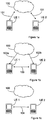
- Figures 1a-1c describes such a discovery procedure in general terms, where figure 1a is an illustration of two UEs, UE 1 and UE 2 which have established a communication via a communication link 101, provided via a wide area or a common communication network 100.
- UE 1 is obtaining information, referred to as probe signaling information 102a which includes a first probe token via communication network 100, while UE 2 is obtaining another set of probe signaling information 102b, comprising a second probe token.
- the probe signaling information sent to UE 1, including the probe token, may originate from a node in the network 100, as indicated in the figure, or from UE 2, or be a combination of information provided by these two entities.
- additional information exchange is executed by initiating probe signaling messages exchange 103 between the two UEs, where one or both probe tokens obtained via the probe signaling information is exchanged with the opposite UE, in this case UE 2, in association with the probe signaling message exchange.
- Probe signaling messages exchange Instructions on how to execute the probe signaling messages exchange may, at least partially, be obtained via the probe signaling information.
- each UE may have preconfigured instructions stored, such that the probe signaling message exchange can be executed according to the obtained probe signaling information in combination with pre-stored UE and/or user specific instructions.
- information on how to execute the described discovery process may be stored in advance in the respective UEs.
- each set of probe signaling information may be restricted to only comprise respective probe token and an instruction or indication that the UE shall proceed according to the instructions stored at the UE.
- probe tokens enable one of the UEs to identify the other as a trusted party with which a direct radio communication link can be used for communication.
- UE 1 can compare the first probe token obtained via the communication network with a second probe token obtained from UE 2 in a probe signaling message. Based on the comparison of the two probe tokens a probing report is generated by UE 1 and provided to either UE 2, or to the communication network 100.
- a response is provided to one or both of the UE's.
- the probing report is sent to the communication network 100 which responds to UE 1 after having evaluated the probing report. If, as a result from the evaluation of the content of the probing report, it is found that use of a direct radio communication link is favorable for the two UE's the response sent to UE 1 will comprise instructions for UE 1 and UE 2 to set up and use a direct radio communication link 104, as indicated with figure 1 c.
- direct radio communications 103 and 104 may be provided on the same communication link or may be separate links, where the first link is typically used for making link measurements, which can later be used in a probing report.
- One or more pre-defined criteria for applying direct mode communication by using direct radio communication link 104 has to be fulfilled in order to provide a positive response to the probing report, where evaluation of the pre-defined criteria may typically be based on data provided in the probing report.
- UE 1 and UE 2 are communicating via the same communication network 100, in the examples provided in this disclosure, the UEs may alternatively communicate via separate communication networks which are inter-connected in a conventional way.
- Fig 2-6 illustrates five different scenarios for initiating and executing what can be referred to as a discovery process, comprising a probing process.
- a discovery process comprising a probing process.
- UE 1 As a prerequisite for all five scenarios a first UE, UE 1 is initially engaged in a connection, or a set-up of a connection with another UE, UE 2 via a common communication network, represented by network node 200 in the figures.
- the probing signaling information may arrive in signaling messages for connectivity establishment, which may result in a set-up of direct link or connectivity over the common communication network, depending on the result of the evaluation of the probing report.
- the conditions for, and examples given in association with executing different steps in one embodiment mentioned below may be applicable also for the other embodiments.
- UE 1 initially receives a first set of probe signaling information, PSI 1, comprising a first probe token PT 1. This first step is indicated as a step 2:1a in figure 2 .
- PSI 2 is receiving a second set of probe signaling information, PSI 2, comprising a second probe token PT 2.
- PSI 1 and PSI 2 may comprise only the respective probe token, while instructions necessary for handling the probe tokens accordingly may already be available at the respective UE.
- the probe signaling information is provided from the network and network node 200, i.e. the probing process is triggered in the network.
- the probing process may be triggered by one or more trigger criteria.
- One basic criterion to consider is the distance between the two UEs, such that when the distance between the two UEs is less than a pre-defined maximum distance, which typically relates to the coverage of technique supporting the direct radio link, the probing process is triggered by transmitting probe signaling information 1 to UE 1.
- the distance between the two UEs may be estimated using any type of conventional distance measuring arrangement.
- the type of service or session such as e.g. a request for making a file transfer, may be considered in order to determine whether a continuing communication via a direct radio communication link is to be preferred.
- UE 1 initiates an exchange of probe signaling messages with UE 2, according to instructions acquired in the probe signaling information or as previously determined between the parties and stored at the respective UE, or as a combination of both.
- one of the UEs may be informed in the probe signaling information to listed for a specific token and how to continue the process once acquired, while the other UE may be instructed how to handle a probe token included in acquired probe signaling information.
- the probe signaling information also comprises a probe token, having the purpose of enabling a UE being in possession of the probe token to compare the acquired probe token with another probe token received via another transmission channel or generated by the UE itself, such that the opposite UE can be identified as a trusted UE. More specifically, a UE, in the present case UE 1, which has received a first probe token PT 1, from, or via the communication network, compares the first probe token to a second probe token PT 2, received from the opposite UE, in the present case UE 2, as part of the probe signaling message exchange, as indicated with a step 2:2. It is to be understood that the probe signaling message exchange described in this and the subsequent scenarios may comprise one or more messages exchanged between the two UEs.
- the probe tokens PT1 and PT2 used by the UEs for identification purpose are assumed to have a pre-determined relationship, e.g. the two probe tokens are identical, one is a specific function of the other, or a function of both will give a determined value during comparison. If the two probe tokens are considered to be related, i.e. they are found to have the pre-determined relationship after a comparison of the two probe tokens, executed in a step 2:3, UE 1 can consider the respective message from UE 2 as trustworthy and can continue the initiated process by generating a probing report, as indicate in another step 2:4.
- the described probe token exchange may be executed in a number of alternative ways, such that either one or both of the UEs may exchange a respective probe token acquired via the common network via a direct radio communication link, thereby enabling one or both of the UEs to compare probe tokens.
- the receiving UE regards the sending UE as the intended sender and further processes the radio measurements made according to probe signaling instructions, the process can continue, while the probing process is interrupted or aborted in case no probing token entailing a successful comparison can be detected while following the probe signaling instructions.
- the probing report will serve as a final verification of the ongoing probing process, such that the UE which is generating the probing report, in the present example UE1, may use at least some information obtained in the exchanged probe signaling messages and optionally also additional information which may indicate whether direct mode communication is to be preferred under the present circumstances.
- Radio condition measurements will in a basic scenario result in the determination of the distance between the UEs, i.e. if the UEs are close enough for using a direct radio communication link the UEs will be instructed to use such a communication link.
- the radio condition measurements may comprise one or more of the signal strength, signal to noise ratio, path loss or the interference experienced by the UE generating the probing report when communicating with the opposite UE, or the power received by the same UE from the opposite UE are measures that may be considered.
- the probing report is transmitted to the network node 200, where it is evaluated, as indicated in another step 2:6.
- information obtained in the probing report may be used in combination with other conditional instructions available at the network node 200, for determining whether a direct radio communication link should be established and used for the continuing communication between the two UEs.
- the probing report comprises information that after evaluation indicates that a direct radio communication link should be established between UE 1 and UE 2, UE 1 and UE 2 are provided with instructions on how to set up or switch to the direct radio communication link, alternatively the UEs may be instructed to continue to use the direct radio communication link which was used for the probe signaling message exchange.
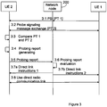
- FIG. 3 is another signaling diagram which illustrates another example of a particular scenario, where one of the UEs, namely UE 1, is provided with functionality for triggering the suggested probing process instead of network node 200.
- UE 2 receives probe signaling information, comprising a first probe token, PT 1, from UE 1 via communication network 200. Based on at least parts of the probe signaling information UE1 or UE 2 then starts a probe signaling message exchange procedure, as indicated with another step 3:2.
- a probe signaling message transmitted from UE1 to UE2 comprises a second probe token, PT 2.
- the two probe tokens are tested for relation, e.g.
- radio condition measurements are processed and a probing report is generated by UE 2, as indicated with a subsequent step 3:4, and transmitted to network node 200, as indicated with another step 3:5.
- the probing report is evaluated, as indicated in a subsequent step 3:6, and in case of a favorable evaluation, network node 200 provides relevant direct link instructions to UE 1 and UE 2, in step 3:7a and 3:7b, respectively, such that a direct radio communication link can be established between the two UEs, as indicated with a final step 3:8.
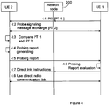
- a third scenario is described with reference to figure 4 , where the probing process is initiated in a corresponding way to the process of figure 3 , but where the probing report is sent to UE 1 instead of to the communication network, as indicated in step 4:5. Consequently, UE 1 evaluates the probing report, as indicated in a step 4:6, and in case of a favorable evaluation UE 1 provides instructions for establishing and using a direct radio communication link in its continuing communication with UE 2, to UE 2, as indicated in a next step 4:7.
- FIG. 5 Yet another scenario is illustrated in figure 5 , where one of the UEs, namely UE 1, is configured to both initiate the discovery process and to generate the probing report.
- UE 1 provides a probe token for later processing by itself, PT 2, and in a subsequent step 5:2 another probe token, PT 1, which is transmitted to UE 2 together with probe signaling information (PSI).
- PSI probe signaling information
- step 5:3 comprises the step of returning PS 1 to UE 1.
- UE 2 compares the two probe tokens and in case of a successful comparison, UE 1 generates a probing report, as indicated with a step 5:5, and transmits the report, in the present case to the network node 200, as indicated with a subsequent step 5:6.
- the network node 200 evaluates the probing report in a step 5:7, and in case of a favorable report, network node 200 provides direct link instructions to the first and the second UE, in steps 5:8a and 5:8b, respectively, such that a direct radio communication link can be used for communication between the two UEs, as indicated with step 5:9.
- steps UE 1 is even more involved in the discovery process and where the task of the communication network in this context is to provide a first communication between the two UEs.
- steps 6:1-6:5 correspond to steps 5:1-5:5 of figure 5 .
- step 6:2 there is no need to involve any network node.
- UE 1 takes care of the evaluation of the probing report by itself, as indicated in a step 6:6. The evaluation is in this case typically done based on a pre-configuration of UE 1 regarding some set of rules determining criteria for a favorable report.
- UE 1 In response to a favorable report, UE 1 generates direct link instructions for itself, as indicated in a step 6:7a and for UE 2, as indicated in another step 6:7b, thereby enabling both UEs to communicate via a direct radio communication link, as indicate in step 6:8.
- FIG. 7 is a flow chart illustrating a series of method steps to be executed in a UE which receives probe signaling information from a communication network node or another UE. Consequently the discovery process is initiated by the UE receiving probe signaling information, including a first probe token, as indicated with a first step 700.
- probe signaling messages including a second probe token and/or the first token, are exchanged between the two UEs.
- one or more probe tokens are exchanged, such that one of the UEs or both UEs can compare the two tokens, as indicated in a step 703, and generate and provide the probing report, as indicated with a step 704. If no probing token is received with measurements made according to probe signaling information, the process is instead terminated, as indicated with a step 707. If the evaluation of the probing report is favorable, instructions to use direct radio link communication is provided to the UE, as indicated with step 705, and the link can be used as indicated with step 706. It is to be understood that steps 702 to 704 are steps which rely on the reception of two related probe tokens which can be compared, thereby enabling the UE to identify the other UE.
- one of the UEs may have a more passive roll, which results in the execution of the steps 700-707 except steps 702 to 704, while the other UE is executing steps 700-707.
- the steps to be executed by the respective UE may depend on instructions available at the respective UEs, instructions provided to the UEs, or a combination thereof.
- Figure 8 is another flow chart illustrating method steps according to one embodiment, which enables a UE to initiate a probing process.
- the method starts by reception of one or more probing triggers from an internal or external trigger source, or a combination thereof.
- a basic trigger may be an indication that the two UEs are located in close vicinity to each other.
- the type of service selected by the users of the UEs may also be considered.
- the UE transmits probe signaling information together with a probe token to the opposite UE, as indicated with a step 801, and in a subsequent step 802, probe signaling messages are exchanged between the two UEs.
- the probing report may be provided to the UE itself or to the opposite UE, as indicated in a step 803a, or to the UE from the opposite UE, as indicated in the alternative step 803b.
- steps which corresponds to steps 702-704 in figure 7 will be executed, such that only in case of a successful comparison of probe tokens, a probing report will be provided and made available to one of the UEs.
- a subsequent step 804 the self-generated or received probing report is evaluated, and in case of a favorable report, which is determined in another step 805, the UE will provide instructions to use a direct radio communication link to the opposite UE, and to itself, as indicated in another step 806a, before the UEs can use the direct radio communication link according to the provided instructions, as indicated in a final step 806.
- the evaluation of the probing report is to be performed by an entity other than the UE executing the method steps described above, the exchange of probe signaling messages according to step 802 will be followed by the reception of instructions to use a direct radio communication link from the entity by which the probing report was evaluated.
- Such an alternative step is indicated with a step 806b. and the report is evaluated in a subsequent step 804a.
- a corresponding method has to be executed in a network node of the communication network.
- a method according to one exemplary embodiment will therefore be described below with reference to the flow chart of figure 9 , where one or more probing triggers are first received, either internally or from an external triggering source, as indicated with a first step 900, after which probe signaling information is transmitted to the UEs as indicated with a subsequent step 901.
- a probing report is received and evaluated, as indicated in a next step 902, and in case of a favorable evaluation, which is determined in a step 903, instructions to use a direct radio communication link are transmitted to one or both UEs, as indicated in a final step 904.
- a UE In order for a UE to be able to execute the process described above, it has to be provided with functionality adapted therefore, and thus, in addition of functionality which is normally necessary for providing communication facilities, which will be omitted for simplicity reasons, a plurality of functional units will have to be configured to interact with each other accordingly. Such a UE will now be described with reference to figure 10 .
- a first UE, UE 1 is connectable to a second UE, UE 2, as well as to a communication network, wherein in the former case, connection is obtained via a direct radio communication link, while in the latter case, connection involve conventional access nodes (not shown), as well as additional network nodes, here represented by network node 200, which is provided with functionality for participating in the probing process described above.
- UE 1 comprises a communication unit 1001 for receiving probe signaling information via the communication network, wherein the probe signaling information initiates the execution of a probing process at UE 1.
- UE 1 also comprises a unit referred to as a probe handing unit 1002 which is configured to exchange, at least partly according to the acquired probe signaling information, probe signaling messages including the first and/or a second probe token with the second user equipment over a direct radio communication link.
- probe handing unit 1002 is configured to exchange, at least partly according to the acquired probe signaling information, probe signaling messages including the first and/or a second probe token with the second user equipment over a direct radio communication link.
- the probe handling unit 1002 is also configured to generate a probing report which, at least partially, is based on content exchanged via probe signaling messages exchanged between the two UEs, and to provide the generated probing report to a node of the communication network, or the second UE UE 2 for evaluation.
- the communication unit 1001 is further configured to use a second direct radio communication link for communication with the second UE UE 2, according to instructions provided from the entity by which the probing report was evaluated, i.e. from the second UE UE 2 or from network node 200.
- instructions may be provided by the probe handling unit 1002 of UE 1, in response to a favorable evaluation of a probing report, executed by the probe handling unit 1002.
- the probe handling unit 1002 is also configured to compare a first probe token and a second probe token and to generate a probing report in case of a successful comparison.
- the first UE UE 1 described above is configured to participate in a probing process triggered at a network node 200 or at a second UE UE 2.
- a UE which is configured to participate in a probing process such as the one of the alternative processes described above may however also be configured to initiate such a probing process.
- the first UE UE 1 will have to be adapted accordingly.
- the first UE UE 1 may therefore also be provided with a unit, here referred to as probing unit 1003, which is configured to generate probe signaling information, a first and a second probe token to be used for UE identification, and to provide the probe signaling information and one or both of the generated probe tokens to the second UE UE 2.
- the probing unit 1003 is configured to transmit the probe signaling information, via communication unit 1001 and the communication network node 200.
- the first UE UE 1 may also be provided with functionality for triggering the probing process at the UE.
- such functionality is provided in a unit, referred to as a probing triggering unit 1004.
- the probing triggering unit 1004 is configured to trigger the communication unit 1001 to transmit probe signaling information to the second UE UE 2, and possibly also to provide corresponding probe signaling information to UE 1 itself when one or more trigger criteria has been fulfilled.
- the triggering is typically based on data provided from one or more external sources, such as e.g. a distance estimating entity, configured according to any conventional technique, but may also be, at least partially, based on data generated internally by the probing triggering unit 1003.
- the probing triggering unit 1004 is configured to trigger the transmission of probe signaling information in case it is determined by the probing triggering unit 1004 that all required criteria is fulfilled.
- the probing triggering unit 1004 may be configured to acquire an estimate of a distance between the first UE UE 1 and the second UE UE 2 and to trigger the transmission of probe signaling information in case the estimated distance is less than a pre-defined maximum distance, typically the transmitting range for the direct radio communication link.
- the probing unit 1003 may also be configured to repeat the suggested probing process at a certain repetition rate, for ascertaining that the most suitable means of communication is used at all occasions.
- one or more network nodes of the common communication network via which the two UEs are initially connected also have to be adapted accordingly.
- One such network node 200 will therefore be described in further detail below, with reference to figure 11 . It is to be understood that although the functionality of the common communication network is provided in one single network node in figure 11 , the suggested functionality may alternatively be distributed on two or more nodes of, or accessible to the communication network, in addition to network node 200.
- Network node 200 comprises a probing unit 1100, a communication unit 1101 and a probing triggering unit 1102 which has functionality which corresponds to the corresponding functionality of the UE described above with reference to figure 10 . More specifically, probing unit 1100 is configured to transmit a first set of probe signaling information comprising a first probe token to the first UE UE 1 or the second UE UE 2 via communication unit 1101 ,and a second set of probe signaling information comprising a second probe token to the opposite UE. The probing unit 1100 is also configured to receive and evaluate a probing report transmitted from any of the UEs.
- the probing triggering unit 1102 of network node 200 is configured to trigger the communication unit 1101 to transmit probe signaling information to the second and/or first UE when one or more trigger criteria has been fulfilled.
- probing triggering unit 1102 is configured to acquire an estimate on a distance between the first and the second UE and to trigger the probing process by initiating the transmission of probe signaling information in case the estimated distance is less than a pre-defined maximum distance.
- the probing triggering unit 1102 may be configured to determine whether at least one additional criterion for transmitting probe signaling information to one or both of the first UE 1 and second UE UE 2 is fulfilled and to trigger the transmission of probe signaling information in case all required criteria is fulfilled.
- the probing unit 1100 may be configured to repeat the suggested probing process at a certain repetition rate.
- repeated probing may be applied, where a device initiating a probing process may make available a hash chain of probe tokens to the UEs, according to any conventional mechanism for providing hash chains.
- the last probe token of a chain may be sent during establishment of a direct radio communication link, wherein for each subsequent, repeated probing process the current last non-disclosed probe token is sent.
- the receiving UE keeps track of the latest received probe token and compares a corresponding probe token, obtained via a candidate probing message with the last probe token, such that the sending UE can be authenticated.
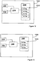
- FIG 12 schematically shows an embodiment of a UE, UE 1, which also can be an alternative way of disclosing an embodiment of the UE, UE 1, illustrated in figure 10 .
- a processing unit 1206 e.g. with a DSP (Digital Signal Processor) and an encoding and a decoding module.
- the processing unit 1206 can be a single unit or a plurality of units to perform different steps of procedures described herein.
- the UE 1 1200 also comprises the input unit 1202 for receiving signals, and the output unit 1204 for output signal(s).
- the input unit 1202 and the output unit 1204 may be arranged as one in the hardware of the UE.
- the UE 1200 comprises at least one computer program product 1208 in the form of a non-volatile memory, e.g. an EEPROM (Electrically Erasable Programmable Read-Only Memory), a flash memory and a disk drive.
- the computer program product 1208 comprises a computer program 1210, which comprises code means, which when run in the processing unit 1206 in the UE 1200 causes the UE to perform the steps of the procedures described earlier in conjunction with figure 7 and 8 , respectively.
- the code means in the computer program 1210 of the UE 1200 comprises a communication module 1210a for receiving probe signaling information, a probe handling module 1210b for exchanging probe signaling messages, a probing module 1210c, for generating and providing probe signaling information, and a probing triggering module 1210d for for triggering the probing process at the UE.
- the computer program 1210 is in the form of computer program code structured in computer program modules.
- the modules 1210a-d essentially perform the steps of the flows illustrated in figure 7 or 8 , to emulate the UE illustrated in figure 10 . In other words, when the different modules 1210a-d are run on the processing unit 1206, they correspond to the units 1001-1004 of figure 10 .
- FIG. 13 schematically shows network node 200, which also can be an alternative way of disclosing an embodiment of the network node, illustrated in figure 11 .
- the processing unit 1306 can be a single unit or a plurality of units to perform different steps of procedures described herein.
- the network node 1300 also comprises the input unit 1302 for receiving signals, and the output unit 1304 for output signal(s).
- the input unit 1302 and the output unit 1304 may be arranged as one in the hardware of the network node.
- the network node 1300 comprises at least one computer program product 1308 in the form of a non-volatile memory, e.g. an EEPROM (Electrically Erasable Programmable Read-Only Memory), a flash memory and a disk drive.
- the computer program product 1308 comprises a computer program 1310, which comprises code means, which when run in the processing unit 1306 in the network node 1300 causes the network node to perform the steps of the procedure described earlier in conjunction with figure 9 .
- the code means in the computer program 1310 of the network node 200 comprises a communication module 1310a for exchanging probe signaling messages, a probing module 1310b, for exchanging probe signaling messages, and a probing triggering module 1210c for triggering transmission of probe signaling information to the second and/or first UE when one or more trigger criteria has been fulfilled.
- the computer program 1310 is in the form of computer program code structured in computer program modules.
- the modules 1310a-c essentially perform the steps of the flow illustrated in figure 9 , to emulate the network node illustrated in figure 11 . In other words, when the different modules 1310a-c are run on the processing unit 1306, they correspond to the units 1100-1102 of figure 11 .
- code means in the embodiments disclosed above in conjunction with figures 12 and 13 are implemented as computer program modules, which when run on the processing unit causes the UE and network node, respectively, to perform the steps described above in the conjunction with figures mentioned above, at least one of the code means may in alternative embodiments be implemented at least partly as hardware circuits.
- the functional modules 1200a-d and 1300a-c described above can be implemented as program modules of a computer program comprising code means, which when run by a processor in the UE and network node, respectively, causes these devices to perform the above-described functions and actions.
- the processor may not only be a single CPU (Central processing unit), but could comprise two or more processing units in the devices.
- the processor may include general purpose microprocessors, instruction set processors and/or related chips sets and/or special purpose microprocessors such as ASICs (Application Specific Integrated Circuit).
- the processor may also comprise board memory for caching purposes.
- the computer program may be carried by a computer program product in the UE or network node, respectively, connected to the processor.
- the computer program product comprises a computer readable medium on which the computer program is stored.
- the computer program product may be a flash memory, a RAM (Random-access memory) ROM (Read-Only Memory) or an EEPROM (Electrically Erasable Programmable ROM), and the computer program modules described above could in alternative embodiments be distributed on different computer program products in the form of memories within the UE and network node, respectively.
Landscapes
- Engineering & Computer Science (AREA)
- Computer Networks & Wireless Communication (AREA)
- Signal Processing (AREA)
- Mobile Radio Communication Systems (AREA)
Claims (14)
- Verfahren in einer ersten Benutzervorrichtung, die über ein Kommunikationsnetzwerk oder über eine direkte Funkkommunikationsverbindung mit einer zweiten Benutzervorrichtung verbunden werden kann, der Verwendung einer direkten Funkkommunikationsverbindung zur Kommunikation zwischen der ersten und der zweiten Benutzervorrichtung, wobei das Verfahren Folgendes umfasst:- Übertragen (801), über das Kommunikationsnetzwerk, von Sondensignalisierungsinformationen, die eine erste Sondenmarke umfassen, an die zweite Benutzervorrichtung, oder Empfangen (700), über das Kommunikationsnetzwerk, von Sondensignalisierungsinformationen, die eine erste Sondenmarke umfassen;- Austauschen (802, 701), mindestens teilweise gemäß den Sondensignalisierungsinformationen, von Sondensignalisierungsnachrichten, einschließlich einer zweiten und/oder der ersten Sondenmarke, mit der zweiten Benutzervorrichtung über eine erste direkte Funkkommunikationsverbindung, wodurch der ersten oder der zweiten Benutzervorrichtung Folgendes ermöglicht wird: Vergleichen der ersten und der zweiten Sondenmarke; Erzeugen eines Sondierungsberichts und Bewerten des Sondierungsberichts, oder Bereitstellen des Sondierungsberichts für einen Knoten des Kommunikationsznetzwerks oder für die gegenüberliegende Benutzervorrichtung zur Bewertung im Fall eines erfolgreichen Vergleichs, wobei der Sondierungsbericht mindestens teilweise auf Inhalten basiert, die über die Sondensignalisierungsnachrichten ausgetauscht werden, und- Verwenden (806, 706) einer zweiten direkten Funkkommunikationsverbindung zur Kommunikation mit der zweiten Benutzervorrichtung als Reaktion auf das Erhalten (806a; 806b) oder das Empfangen (705) von Anweisungen zur Verwendung der zweiten direkten Funkkommunikationsverbindung, von der Entität, durch die der Sondierungsbericht bewertet wurde.
- Verfahren nach Anspruch 1, wobei die erste Sondenmarke der zweiten Benutzervorrichtung zusammen mit Sondensignalisierungsinformationen bereitgestellt wird und die zweite Sondenmarke der zweiten Benutzervorrichtung während des Sondensignalisierungsaustauschs bereitgestellt wird.
- Verfahren nach Anspruch 1, das Folgendes umfasst:- Bereitstellen (5:1) einer zweiten Sondenmarke für eine spätere Verarbeitung durch die erste Benutzervorrichtung;- Empfangen (5:3) der ersten Sondenmarke von der zweiten Benutzervorrichtung;- Vergleichen (5:4) der ersten und der zweiten Sondenmarke;- Erzeugen (5:5) eines Sondierungsberichts im Falle eines erfolgreichen Vergleichs;- Übertragen (5:6) des Sondierungsberichts an den Netzknoten und- Empfangen (5:8b) einer Anweisung von dem Netzwerkknoten, der die erste Benutzervorrichtung anweist, die zweite direkte Funkkommunikationsverbindung zur Kommunikation mit der gegenüberliegenden Benutzervorrichtung zu verwenden (6:9), falls die Bewertung des Sondierungsberichts die Verwendung einer derartigen Kommunikationsverbindung zulässt.
- Verfahren nach Anspruch 1, das Folgendes umfasst:- Bereitstellen (6:1) einer zweiten Sondenmarke für eine spätere Verarbeitung durch die erste Benutzervorrichtung;- Empfangen (6:2) der ersten Sondenmarke von der zweiten Benutzervorrichtung;- Vergleichen (6:3) der ersten und der zweiten Sondenmarke;- Erzeugen (6:4) eines Sondierungsberichts im Falle eines erfolgreichen Vergleichs;- Bewerten (6:5) des Sondierungsberichts und- Übertragen (6:6b) einer Anweisung an die zweite Benutzervorrichtung, um diese anzuweisen, die zweite direkte Funkkommunikationsverbindung zur Kommunikation mit der gegenüberliegenden Benutzervorrichtung zu verwenden (6:7), falls die Bewertung des Sondierungsberichts die Verwendung einer derartigen Kommunikationsverbindung zulässt.
- Verfahren nach einem der vorhergehenden Ansprüche, wobei die Sondensignalisierungsinformationen Anweisungen für mindestens die erste oder die zweite Benutzervorrichtung für Folgendes umfassen:- Horchen auf die erste oder die zweite Sondenmarke und/oder- Übertragen der ersten oder der zweiten Sondenmarke gemäß den Sondensignalisierungsinformationen an die gegenüberliegende Benutzervorrichtung und/oder- Übertragen mindestens eines Teils der Signalisierungsinformationen an die gegenüberliegende Benutzervorrichtung.
- Verfahren nach einem der vorhergehenden Ansprüche, das ferner Folgendes umfasst:- Empfangen (803b) eines Sondierungsberichts von der gegenüberliegenden Benutzervorrichtung;- Bewerten (804) des Sondierungsberichts und- Bereitstellen (806a) einer Anweisung für die Benutzervorrichtung, von der der Sondierungsbericht empfangen wurde, um sie anzuweisen, die zweite direkte Funkkommunikationsverbindung zur Kommunikation mit der gegenüberliegenden Benutzervorrichtung zu verwenden, falls die Bewertung des Sondierungsberichts die Verwendung einer derartigen Kommunikationsverbindung zulässt.
- Verfahren in einem Netzwerkknoten eines Kommunikationsnetzwerks, das in der Lage ist, den Aufbau einer direkten Funkkommunikationsverbindung zwischen einer ersten Benutzervorrichtung und einer zweiten Benutzervorrichtung zu unterstützen, wobei das Verfahren Folgendes umfasst:- Übertragen (901) eines ersten Satzes von Sondensignalisierungsinformationen (PSI 1), die eine erste Sondenmarke umfassen, an die erste oder zweite Benutzervorrichtung und eines zweiten Satzes von Sondensignalisierungsinformationen (PSI 2), die eine zweite Sondenmarke umfassen, an die gegenüberliegende Benutzervorrichtung, wodurch Folgendes ermöglicht wird:- für die erste und die zweite Benutzervorrichtung: Austauschen von Sondensignalisierungsnachrichten, einschließlich der ersten und/oder der zweiten Sondenmarke, über die erste direkte Funkkommunikationsverbindung mindestens teilweise gemäß den Sondensignalisierungsinformationen, und für mindestens eine der ersten oder der zweiten Benutzervorrichtung: Vergleichen der Sondenmarke; bei erfolgreichem Vergleich erfolgendes Erzeugen eines Sondierungsberichts, der mindestens teilweise auf Inhalten basiert, die über die Sondensignalisierungsnachrichten ausgetauscht werden, und Bereitstellen des Sondierungsberichts für den Netzwerkknoten oder die gegenüberliegende Benutzervorrichtung zur Bewertung, so dass die erste und die zweite Benutzervorrichtung eine zweite direkte Funkkommunikationsverbindung für die Kommunikation zwischen den beiden Benutzervorrichtungen verwenden können als Reaktion auf das Empfangen von Anweisungen zur Verwendung der zweiten direkten Funkkommunikationsverbindung, von der Entität, durch die der Sondierungsbericht bewertet wurde.
- Verfahren nach Anspruch 7, das ferner Folgendes umfasst:- Empfangen (902) des Sondierungsberichts von der ersten oder der zweiten Benutzervorrichtung;- Bewerten des Sondierungsberichts und- Übertragen (904) von Anweisungen an mindestens eine der ersten und der zweiten Benutzervorrichtung, um die Benutzervorrichtung(en) anzuweisen, die zweite direkte Funkkommunikationsverbindung zur Kommunikation mit der gegenüberliegenden Benutzervorrichtung zu verwenden, falls die Bewertung des Sondierungsberichts die Verwendung einer derartigen Kommunikationsverbindung unterstützt.
- Verfahren nach einem der Ansprüche 7 bis 8, das ferner Folgendes umfasst:- Erfassen von entfernungsbezogenen Informationen, die eine geschätzte Entfernung zwischen der ersten und der zweiten Benutzervorrichtung angeben und- Auslösen der Übertragung der Sondensignalisierungsinformationen, falls die geschätzte Entfernung geringer als eine vordefinierte maximale Entfernung ist.
- Verfahren nach Anspruch 9, das ferner Folgendes umfasst:- Bestimmen, ob mindestens ein zusätzliches Kriterium zum Übertragen von Sondensignalisierungsinformationen an eine oder beide der ersten und zweiten Benutzervorrichtungen erfüllt ist und- Auslösen der Übertragung der Sondensignalisierungsinformationen, falls festgestellt wird, dass das erforderliche Kriterium erfüllt ist.
- Verfahren nach Anspruch 10, wobei der Sondierungsbericht mindestens eines von Folgendem umfasst:- eine Angabe der Signalstärke, die von der gegenüberliegenden Benutzervorrichtung empfangen wurde, von der der Sondierungsbericht übertragen wurde;- eine Angabe der Leistung, die von der gegenüberliegenden Benutzervorrichtung empfangen wurde, durch die Entität, von der der Sondierungsbericht übertragen wurde;- eine Schätzung des Signal-Rausch-Verhältnisses, das die Entität erfährt, von der der Sondierungsbericht übertragen wurde;- eine Angabe der Interferenzen, die die Entität erfährt, von der der Sondierungsbericht übertragen wurde, und- eine Schätzung des Pfadverlustes zwischen den Benutzervorrichtungen.
- Erste Benutzervorrichtung (UE 1), die über ein Kommunikationsnetzwerk oder über eine direkte Funkkommunikationsverbindung mit einer zweiten Benutzervorrichtung (UE 2) verbunden werden kann, wobei die erste Benutzervorrichtung (UE 1) Folgendes umfasst:- eine Kommunikationseinheit (1001), die so konfiguriert ist, dass sie über einen Netzwerkknoten (200) des Kommunikationsnetzwerks Sondensignalisierungsinformationen empfängt oder überträgt, die eine erste Sondenmarke umfassen;- eine Sondenhandhabungseinheit (1002), die so konfiguriert ist, dass sie mindestens teilweise gemäß den Sondensignalisierungsinformationen Sondensignalisierungsnachrichten, einschließlich einer zweiten und/oder der ersten Sondenmarke, mit der zweiten Benutzervorrichtung (UE 2) über eine erste direkte Funkkommunikationsverbindung austauscht, wodurch ermöglicht wird, dass mindestens die erste (UE 1) oder die zweite Benutzervorrichtung (UE 2) Folgendes ausführt: Vergleichen der ersten und der zweiten Sondenmarke; Erzeugen eines Sondierungsberichts und Bewerten des Sondierungsberichts oder Bereitstellen des Sondierungsberichts für einen Knoten des Kommunikationsznetzwerks oder für die gegenüberliegende Benutzervorrichtung zur Bewertung im Fall eines erfolgreichen Vergleichs, wobei der Sondierungsbericht mindestens teilweise auf Inhalten basiert, die über die Sondensignalisierungsnachrichten ausgetauscht werden,wobei die Kommunikationseinheit (1001) ferner dafür konfiguriert ist, eine zweite direkte Funkkommunikationsverbindung für die Kommunikation mit der zweiten Benutzervorrichtung gemäß Anweisungen zu verwenden, die von der Entität bereitgestellt werden, durch die der Sondierungsbericht bewertet wurde.
- Netzwerkknoten (200) eines Kommunikationsnetzwerks, das in der Lage ist, den Aufbau einer direkten Funkkommunikationsverbindung zwischen einer ersten Benutzervorrichtung (UE 1) und einer zweiten Benutzervorrichtung (UE 2) zu unterstützen, wobei der Netzwerkknoten (200) Folgendes umfasst:- eine Sondierungseinheit (1100), die zum Übertragen von Folgendem konfiguriert ist: eines ersten Satzes von Sondensignalisierungsinformationen, die eine erste Sondenmarke umfassen, an die erste oder zweite Benutzervorrichtung und eines zweiten Satzes von Sondensignalisierungsinformationen, die eine zweite Sondenmarke umfassen, an die gegenüberliegende Benutzervorrichtung über eine Kommunikationseinheit (1101), wodurch Folgendes ermöglicht wird:- für die erste (UE 1) und die zweite Benutzervorrichtung (UE 2): Austauschen von Sondensignalisierungsnachrichten, einschließlich der ersten und/oder der zweiten Sondenmarke, über die erste direkte Funkkommunikationsverbindung mindestens teilweise gemäß den Sondensignalisierungsinformationen, wodurch der ersten oder der zweiten Benutzervorrichtung Folgendes ermöglicht wird: Vergleichen der empfangenen Sondenmarken; bei erfolgreichem Vergleich erfolgendes Erzeugen eines Sondierungsberichts, der mindestens teilweise auf Inhalten basiert, die über die Sondensignalisierungsnachrichten ausgetauscht werden, und Bereitstellen des Sondierungsberichts für den Netzwerkknoten oder die gegenüberliegende Benutzervorrichtung zur Bewertung, so dass die erste (UE 1) und die zweite Benutzervorrichtung (UE 2) eine zweite direkte Funkkommunikationsverbindung zur Kommunikation verwenden können als Reaktion auf den Empfang von Anweisungen von der Entität, durch die der Sondierungsbericht bewertet wurde, die zweite direkte Funkkommunikationsverbindung zur Kommunikation zwischen den beiden Benutzervorrichtungen zu verwenden.
- Netzwerkknoten (200) nach Anspruch 13, wobei der Netzwerkknoten ferner eine Sondierungsauslöseeinheit (1102) umfasst, die dafür konfiguriert ist, die Kommunikationseinheit (1101) zum Übertragen von Sondensignalisierungsinformationen an die zweite (UE 2) und die erste Benutzervorrichtung (UE 1) auszulösen, wenn ein oder mehrere Auslöserkriterien erfüllt sind.
Applications Claiming Priority (1)
| Application Number | Priority Date | Filing Date | Title |
|---|---|---|---|
| PCT/SE2010/050708 WO2011162649A1 (en) | 2010-06-22 | 2010-06-22 | Methods and arrangements for direct mode communication |
Publications (3)
| Publication Number | Publication Date |
|---|---|
| EP2586264A1 EP2586264A1 (de) | 2013-05-01 |
| EP2586264A4 EP2586264A4 (de) | 2016-03-02 |
| EP2586264B1 true EP2586264B1 (de) | 2017-03-29 |
Family
ID=45371637
Family Applications (1)
| Application Number | Title | Priority Date | Filing Date |
|---|---|---|---|
| EP10853763.0A Not-in-force EP2586264B1 (de) | 2010-06-22 | 2010-06-22 | Verfahren und anordnungen für kommunikation im direktmodus |
Country Status (4)
| Country | Link |
|---|---|
| US (1) | US8934892B2 (de) |
| EP (1) | EP2586264B1 (de) |
| CN (1) | CN102960045B (de) |
| WO (1) | WO2011162649A1 (de) |
Families Citing this family (3)
| Publication number | Priority date | Publication date | Assignee | Title |
|---|---|---|---|---|
| JP6062654B2 (ja) * | 2012-04-25 | 2017-01-18 | 株式会社Nttドコモ | 無線通信端末及び通信方法 |
| WO2014117383A1 (zh) * | 2013-02-01 | 2014-08-07 | 华为技术有限公司 | 一种识别网络中设备的方法和装置 |
| US9699817B2 (en) * | 2014-12-16 | 2017-07-04 | Qualcomm Incorporated | Methods to preemptively search and select LTE-direct expressions for uninterrupted device-to-device communication |
Family Cites Families (14)
| Publication number | Priority date | Publication date | Assignee | Title |
|---|---|---|---|---|
| US5995500A (en) * | 1997-07-18 | 1999-11-30 | Telefonaktiebolaget Lm Ericsson | Method and apparatus for direct communication between mobile stations |
| US7016673B2 (en) * | 2002-10-01 | 2006-03-21 | Interdigital Technology Corporation | Wireless communication method and system with controlled WTRU peer-to-peer communications |
| CN1883167B (zh) * | 2003-11-20 | 2013-08-21 | 皇家飞利浦电子股份有限公司 | 一种用于在无线网络的第一站和第二站之间直接通信的方法 |
| US7814322B2 (en) * | 2005-05-03 | 2010-10-12 | Sri International | Discovery and authentication scheme for wireless mesh networks |
| US7577125B2 (en) * | 2005-07-08 | 2009-08-18 | Microsoft Corporation | Direct wireless client to client communication |
| EP1843543B1 (de) * | 2006-04-06 | 2018-12-12 | Google Technology Holdings LLC | Verfahren, Vorrichtung und System zur Authentifizierung in einem Peer-to-Peer Datei-Austausch Netzwerk |
| EP1998499A1 (de) * | 2007-05-31 | 2008-12-03 | Nokia Siemens Networks Oy | Abfrage für Peer-to-Peer-Verkehr |
| JP4506829B2 (ja) * | 2007-12-26 | 2010-07-21 | ソニー株式会社 | 無線通信システム、無線通信装置、無線通信方法、およびプログラム |
| US20100128701A1 (en) * | 2008-11-24 | 2010-05-27 | Qualcomm Incorporated | Beacon transmission for participation in peer-to-peer formation and discovery |
| US8737316B2 (en) * | 2009-05-01 | 2014-05-27 | Qualcomm Incorporated | Home agent-less MIPv6 route optimization over WAN |
| US9900759B2 (en) * | 2009-11-04 | 2018-02-20 | Qualcomm Incorporated | Method and apparatus for peer discovery in a wireless communication network |
| US8725880B2 (en) * | 2010-04-07 | 2014-05-13 | Apple, Inc. | Establishing online communication sessions between client computing devices |
| US8934909B2 (en) * | 2010-05-19 | 2015-01-13 | Nokia Corporation | Method and apparatus for providing communication offloading to unlicensed bands |
| WO2011147462A1 (en) * | 2010-05-28 | 2011-12-01 | Nokia Siemens Networks Oy | Method and apparatus for device-to-device communications |
-
2010
- 2010-06-22 CN CN201080067590.XA patent/CN102960045B/zh active Active
- 2010-06-22 WO PCT/SE2010/050708 patent/WO2011162649A1/en active Application Filing
- 2010-06-22 EP EP10853763.0A patent/EP2586264B1/de not_active Not-in-force
- 2010-06-22 US US13/703,677 patent/US8934892B2/en active Active
Also Published As
| Publication number | Publication date |
|---|---|
| WO2011162649A1 (en) | 2011-12-29 |
| US8934892B2 (en) | 2015-01-13 |
| CN102960045A (zh) | 2013-03-06 |
| EP2586264A4 (de) | 2016-03-02 |
| CN102960045B (zh) | 2016-05-18 |
| EP2586264A1 (de) | 2013-05-01 |
| US20130084854A1 (en) | 2013-04-04 |
Similar Documents
| Publication | Publication Date | Title |
|---|---|---|
| US20220303866A1 (en) | Relay selection method and device for sidelink, storage medium and terminal | |
| US20200314801A1 (en) | Multicast-based group communication in ad hoc arrangements of wireless devices | |
| TWI602468B (zh) | Terminal through the relay node to determine the use of methods and devices | |
| TWI504305B (zh) | 用於裝置間(d2d)通信的方法以及設備 | |
| TWI584669B (zh) | A method and apparatus for determining a relay node | |
| JP5420660B2 (ja) | 通信に複数の周波数帯域を使用する方法と装置 | |
| TWI499335B (zh) | 用於無線通信之方法及使用者設備 | |
| WO2014040506A1 (zh) | 终端的发现、发现处理方法及装置 | |
| BR112017016316B1 (pt) | Resposta de acesso aleatório com formação de feixe analógico | |
| JP6817336B2 (ja) | セル・ハンドオーバー方法、基地局および制御ノード | |
| KR20090014068A (ko) | 통신 시스템에서 피어 투 피어 통신 방법 및 시스템 | |
| US10966264B2 (en) | Multi-station support of wireless communications | |
| US20130331103A1 (en) | Apparatus and Method for Selecting HO Triggers | |
| JP2017516430A (ja) | 基地局、ユーザ機器、リソース取得方法、及びシステム | |
| CN114390634A (zh) | 一种中继终端的选择方法、终端及存储介质 | |
| JP2023126773A (ja) | 通信方法及び通信装置 | |
| EP2586264B1 (de) | Verfahren und anordnungen für kommunikation im direktmodus | |
| CN114514726A (zh) | 无线网络中的安全密钥生成 | |
| US8433313B2 (en) | Mobile communication method and mobile communication system | |
| CN112399418B (zh) | 用于通信的方法和装置 | |
| US10237905B2 (en) | Device to device (D2D) communication method and apparatus | |
| Rajadurai et al. | Enhanced interworking of LTE and Wi-Fi direct for public safety | |
| US9713160B2 (en) | Methods and arrangements for allocation of radio resources | |
| GB2506118A (en) | Device-to-device (D2D) connection set-up in a wireless communication system | |
| AU2017426204A1 (en) | Monitoring method and terminal apparatus in internet-of-vehicles system |
Legal Events
| Date | Code | Title | Description |
|---|---|---|---|
| PUAI | Public reference made under article 153(3) epc to a published international application that has entered the european phase |
Free format text: ORIGINAL CODE: 0009012 |
|
| 17P | Request for examination filed |
Effective date: 20121010 |
|
| AK | Designated contracting states |
Kind code of ref document: A1 Designated state(s): AL AT BE BG CH CY CZ DE DK EE ES FI FR GB GR HR HU IE IS IT LI LT LU LV MC MK MT NL NO PL PT RO SE SI SK SM TR |
|
| DAX | Request for extension of the european patent (deleted) | ||
| RA4 | Supplementary search report drawn up and despatched (corrected) |
Effective date: 20160129 |
|
| RIC1 | Information provided on ipc code assigned before grant |
Ipc: H04W 84/18 20090101ALI20160125BHEP Ipc: H04W 76/04 20090101ALI20160125BHEP Ipc: H04W 12/00 20090101ALI20160125BHEP Ipc: H04W 76/02 20090101AFI20160125BHEP |
|
| 17Q | First examination report despatched |
Effective date: 20160208 |
|
| GRAP | Despatch of communication of intention to grant a patent |
Free format text: ORIGINAL CODE: EPIDOSNIGR1 |
|
| INTG | Intention to grant announced |
Effective date: 20161025 |
|
| GRAS | Grant fee paid |
Free format text: ORIGINAL CODE: EPIDOSNIGR3 |
|
| GRAA | (expected) grant |
Free format text: ORIGINAL CODE: 0009210 |
|
| AK | Designated contracting states |
Kind code of ref document: B1 Designated state(s): AL AT BE BG CH CY CZ DE DK EE ES FI FR GB GR HR HU IE IS IT LI LT LU LV MC MK MT NL NO PL PT RO SE SI SK SM TR |
|
| REG | Reference to a national code |
Ref country code: GB Ref legal event code: FG4D |
|
| REG | Reference to a national code |
Ref country code: CH Ref legal event code: EP |
|
| REG | Reference to a national code |
Ref country code: AT Ref legal event code: REF Ref document number: 880835 Country of ref document: AT Kind code of ref document: T Effective date: 20170415 |
|
| REG | Reference to a national code |
Ref country code: IE Ref legal event code: FG4D |
|
| REG | Reference to a national code |
Ref country code: DE Ref legal event code: R096 Ref document number: 602010041202 Country of ref document: DE |
|
| REG | Reference to a national code |
Ref country code: NL Ref legal event code: FP |
|
| PG25 | Lapsed in a contracting state [announced via postgrant information from national office to epo] |
Ref country code: FI Free format text: LAPSE BECAUSE OF FAILURE TO SUBMIT A TRANSLATION OF THE DESCRIPTION OR TO PAY THE FEE WITHIN THE PRESCRIBED TIME-LIMIT Effective date: 20170329 Ref country code: NO Free format text: LAPSE BECAUSE OF FAILURE TO SUBMIT A TRANSLATION OF THE DESCRIPTION OR TO PAY THE FEE WITHIN THE PRESCRIBED TIME-LIMIT Effective date: 20170629 Ref country code: GR Free format text: LAPSE BECAUSE OF FAILURE TO SUBMIT A TRANSLATION OF THE DESCRIPTION OR TO PAY THE FEE WITHIN THE PRESCRIBED TIME-LIMIT Effective date: 20170630 Ref country code: LT Free format text: LAPSE BECAUSE OF FAILURE TO SUBMIT A TRANSLATION OF THE DESCRIPTION OR TO PAY THE FEE WITHIN THE PRESCRIBED TIME-LIMIT Effective date: 20170329 Ref country code: HR Free format text: LAPSE BECAUSE OF FAILURE TO SUBMIT A TRANSLATION OF THE DESCRIPTION OR TO PAY THE FEE WITHIN THE PRESCRIBED TIME-LIMIT Effective date: 20170329 |
|
| REG | Reference to a national code |
Ref country code: AT Ref legal event code: MK05 Ref document number: 880835 Country of ref document: AT Kind code of ref document: T Effective date: 20170329 |
|
| PG25 | Lapsed in a contracting state [announced via postgrant information from national office to epo] |
Ref country code: SE Free format text: LAPSE BECAUSE OF FAILURE TO SUBMIT A TRANSLATION OF THE DESCRIPTION OR TO PAY THE FEE WITHIN THE PRESCRIBED TIME-LIMIT Effective date: 20170329 Ref country code: BG Free format text: LAPSE BECAUSE OF FAILURE TO SUBMIT A TRANSLATION OF THE DESCRIPTION OR TO PAY THE FEE WITHIN THE PRESCRIBED TIME-LIMIT Effective date: 20170629 Ref country code: LV Free format text: LAPSE BECAUSE OF FAILURE TO SUBMIT A TRANSLATION OF THE DESCRIPTION OR TO PAY THE FEE WITHIN THE PRESCRIBED TIME-LIMIT Effective date: 20170329 |
|
| PG25 | Lapsed in a contracting state [announced via postgrant information from national office to epo] |
Ref country code: RO Free format text: LAPSE BECAUSE OF FAILURE TO SUBMIT A TRANSLATION OF THE DESCRIPTION OR TO PAY THE FEE WITHIN THE PRESCRIBED TIME-LIMIT Effective date: 20170329 Ref country code: ES Free format text: LAPSE BECAUSE OF FAILURE TO SUBMIT A TRANSLATION OF THE DESCRIPTION OR TO PAY THE FEE WITHIN THE PRESCRIBED TIME-LIMIT Effective date: 20170329 Ref country code: SK Free format text: LAPSE BECAUSE OF FAILURE TO SUBMIT A TRANSLATION OF THE DESCRIPTION OR TO PAY THE FEE WITHIN THE PRESCRIBED TIME-LIMIT Effective date: 20170329 Ref country code: EE Free format text: LAPSE BECAUSE OF FAILURE TO SUBMIT A TRANSLATION OF THE DESCRIPTION OR TO PAY THE FEE WITHIN THE PRESCRIBED TIME-LIMIT Effective date: 20170329 Ref country code: AT Free format text: LAPSE BECAUSE OF FAILURE TO SUBMIT A TRANSLATION OF THE DESCRIPTION OR TO PAY THE FEE WITHIN THE PRESCRIBED TIME-LIMIT Effective date: 20170329 Ref country code: IT Free format text: LAPSE BECAUSE OF FAILURE TO SUBMIT A TRANSLATION OF THE DESCRIPTION OR TO PAY THE FEE WITHIN THE PRESCRIBED TIME-LIMIT Effective date: 20170329 Ref country code: CZ Free format text: LAPSE BECAUSE OF FAILURE TO SUBMIT A TRANSLATION OF THE DESCRIPTION OR TO PAY THE FEE WITHIN THE PRESCRIBED TIME-LIMIT Effective date: 20170329 |
|
| REG | Reference to a national code |
Ref country code: DE Ref legal event code: R079 Ref document number: 602010041202 Country of ref document: DE Free format text: PREVIOUS MAIN CLASS: H04W0076020000 Ipc: H04W0076100000 |
|
| PG25 | Lapsed in a contracting state [announced via postgrant information from national office to epo] |
Ref country code: PT Free format text: LAPSE BECAUSE OF FAILURE TO SUBMIT A TRANSLATION OF THE DESCRIPTION OR TO PAY THE FEE WITHIN THE PRESCRIBED TIME-LIMIT Effective date: 20170731 Ref country code: IS Free format text: LAPSE BECAUSE OF FAILURE TO SUBMIT A TRANSLATION OF THE DESCRIPTION OR TO PAY THE FEE WITHIN THE PRESCRIBED TIME-LIMIT Effective date: 20170729 Ref country code: PL Free format text: LAPSE BECAUSE OF FAILURE TO SUBMIT A TRANSLATION OF THE DESCRIPTION OR TO PAY THE FEE WITHIN THE PRESCRIBED TIME-LIMIT Effective date: 20170329 Ref country code: SM Free format text: LAPSE BECAUSE OF FAILURE TO SUBMIT A TRANSLATION OF THE DESCRIPTION OR TO PAY THE FEE WITHIN THE PRESCRIBED TIME-LIMIT Effective date: 20170329 |
|
| REG | Reference to a national code |
Ref country code: DE Ref legal event code: R097 Ref document number: 602010041202 Country of ref document: DE |
|
| PG25 | Lapsed in a contracting state [announced via postgrant information from national office to epo] |
Ref country code: DK Free format text: LAPSE BECAUSE OF FAILURE TO SUBMIT A TRANSLATION OF THE DESCRIPTION OR TO PAY THE FEE WITHIN THE PRESCRIBED TIME-LIMIT Effective date: 20170329 Ref country code: MC Free format text: LAPSE BECAUSE OF FAILURE TO SUBMIT A TRANSLATION OF THE DESCRIPTION OR TO PAY THE FEE WITHIN THE PRESCRIBED TIME-LIMIT Effective date: 20170329 |
|
| REG | Reference to a national code |
Ref country code: CH Ref legal event code: PL |
|
| PLBE | No opposition filed within time limit |
Free format text: ORIGINAL CODE: 0009261 |
|
| STAA | Information on the status of an ep patent application or granted ep patent |
Free format text: STATUS: NO OPPOSITION FILED WITHIN TIME LIMIT |
|
| 26N | No opposition filed |
Effective date: 20180103 |
|
| REG | Reference to a national code |
Ref country code: IE Ref legal event code: MM4A |
|
| REG | Reference to a national code |
Ref country code: FR Ref legal event code: ST Effective date: 20180228 |
|
| PG25 | Lapsed in a contracting state [announced via postgrant information from national office to epo] |
Ref country code: IE Free format text: LAPSE BECAUSE OF NON-PAYMENT OF DUE FEES Effective date: 20170622 Ref country code: LI Free format text: LAPSE BECAUSE OF NON-PAYMENT OF DUE FEES Effective date: 20170630 Ref country code: LU Free format text: LAPSE BECAUSE OF NON-PAYMENT OF DUE FEES Effective date: 20170622 Ref country code: CH Free format text: LAPSE BECAUSE OF NON-PAYMENT OF DUE FEES Effective date: 20170630 |
|
| PG25 | Lapsed in a contracting state [announced via postgrant information from national office to epo] |
Ref country code: SI Free format text: LAPSE BECAUSE OF FAILURE TO SUBMIT A TRANSLATION OF THE DESCRIPTION OR TO PAY THE FEE WITHIN THE PRESCRIBED TIME-LIMIT Effective date: 20170329 Ref country code: FR Free format text: LAPSE BECAUSE OF NON-PAYMENT OF DUE FEES Effective date: 20170630 |
|
| REG | Reference to a national code |
Ref country code: BE Ref legal event code: MM Effective date: 20170630 |
|
| PG25 | Lapsed in a contracting state [announced via postgrant information from national office to epo] |
Ref country code: BE Free format text: LAPSE BECAUSE OF NON-PAYMENT OF DUE FEES Effective date: 20170630 |
|
| PG25 | Lapsed in a contracting state [announced via postgrant information from national office to epo] |
Ref country code: MT Free format text: LAPSE BECAUSE OF NON-PAYMENT OF DUE FEES Effective date: 20170622 |
|
| PG25 | Lapsed in a contracting state [announced via postgrant information from national office to epo] |
Ref country code: HU Free format text: LAPSE BECAUSE OF FAILURE TO SUBMIT A TRANSLATION OF THE DESCRIPTION OR TO PAY THE FEE WITHIN THE PRESCRIBED TIME-LIMIT; INVALID AB INITIO Effective date: 20100622 |
|
| PG25 | Lapsed in a contracting state [announced via postgrant information from national office to epo] |
Ref country code: CY Free format text: LAPSE BECAUSE OF NON-PAYMENT OF DUE FEES Effective date: 20170329 |
|
| PG25 | Lapsed in a contracting state [announced via postgrant information from national office to epo] |
Ref country code: MK Free format text: LAPSE BECAUSE OF FAILURE TO SUBMIT A TRANSLATION OF THE DESCRIPTION OR TO PAY THE FEE WITHIN THE PRESCRIBED TIME-LIMIT Effective date: 20170329 |
|
| PG25 | Lapsed in a contracting state [announced via postgrant information from national office to epo] |
Ref country code: TR Free format text: LAPSE BECAUSE OF FAILURE TO SUBMIT A TRANSLATION OF THE DESCRIPTION OR TO PAY THE FEE WITHIN THE PRESCRIBED TIME-LIMIT Effective date: 20170329 |
|
| PG25 | Lapsed in a contracting state [announced via postgrant information from national office to epo] |
Ref country code: AL Free format text: LAPSE BECAUSE OF FAILURE TO SUBMIT A TRANSLATION OF THE DESCRIPTION OR TO PAY THE FEE WITHIN THE PRESCRIBED TIME-LIMIT Effective date: 20170329 |
|
| PGFP | Annual fee paid to national office [announced via postgrant information from national office to epo] |
Ref country code: NL Payment date: 20220626 Year of fee payment: 13 Ref country code: GB Payment date: 20220628 Year of fee payment: 13 |
|
| PGFP | Annual fee paid to national office [announced via postgrant information from national office to epo] |
Ref country code: DE Payment date: 20220629 Year of fee payment: 13 |
|
| REG | Reference to a national code |
Ref country code: DE Ref legal event code: R119 Ref document number: 602010041202 Country of ref document: DE |
|
| REG | Reference to a national code |
Ref country code: NL Ref legal event code: MM Effective date: 20230701 |
|
| GBPC | Gb: european patent ceased through non-payment of renewal fee |
Effective date: 20230622 |
|
| PG25 | Lapsed in a contracting state [announced via postgrant information from national office to epo] |
Ref country code: NL Free format text: LAPSE BECAUSE OF NON-PAYMENT OF DUE FEES Effective date: 20230701 |
|
| PG25 | Lapsed in a contracting state [announced via postgrant information from national office to epo] |
Ref country code: DE Free format text: LAPSE BECAUSE OF NON-PAYMENT OF DUE FEES Effective date: 20240103 Ref country code: GB Free format text: LAPSE BECAUSE OF NON-PAYMENT OF DUE FEES Effective date: 20230622 |