EP2583875A2 - Method and device for controlling a lane departure warning system - Google Patents
Method and device for controlling a lane departure warning system Download PDFInfo
- Publication number
- EP2583875A2 EP2583875A2 EP12181865.2A EP12181865A EP2583875A2 EP 2583875 A2 EP2583875 A2 EP 2583875A2 EP 12181865 A EP12181865 A EP 12181865A EP 2583875 A2 EP2583875 A2 EP 2583875A2
- Authority
- EP
- European Patent Office
- Prior art keywords
- lane
- vehicle
- criterion
- intervention
- deactivation
- Prior art date
- Legal status (The legal status is an assumption and is not a legal conclusion. Google has not performed a legal analysis and makes no representation as to the accuracy of the status listed.)
- Withdrawn
Links
- 238000000034 method Methods 0.000 title claims abstract description 18
- 230000009849 deactivation Effects 0.000 claims abstract description 23
- 230000004913 activation Effects 0.000 claims abstract description 14
- 238000010586 diagram Methods 0.000 description 2
- 210000002023 somite Anatomy 0.000 description 2
- 230000006978 adaptation Effects 0.000 description 1
- 238000013459 approach Methods 0.000 description 1
- 238000010276 construction Methods 0.000 description 1
- 238000012937 correction Methods 0.000 description 1
- 230000003247 decreasing effect Effects 0.000 description 1
- 238000011156 evaluation Methods 0.000 description 1
- 230000002265 prevention Effects 0.000 description 1
- 230000035484 reaction time Effects 0.000 description 1
- 238000012552 review Methods 0.000 description 1
- 230000035939 shock Effects 0.000 description 1
Images


Classifications
-
- B—PERFORMING OPERATIONS; TRANSPORTING
- B60—VEHICLES IN GENERAL
- B60W—CONJOINT CONTROL OF VEHICLE SUB-UNITS OF DIFFERENT TYPE OR DIFFERENT FUNCTION; CONTROL SYSTEMS SPECIALLY ADAPTED FOR HYBRID VEHICLES; ROAD VEHICLE DRIVE CONTROL SYSTEMS FOR PURPOSES NOT RELATED TO THE CONTROL OF A PARTICULAR SUB-UNIT
- B60W30/00—Purposes of road vehicle drive control systems not related to the control of a particular sub-unit, e.g. of systems using conjoint control of vehicle sub-units
- B60W30/10—Path keeping
- B60W30/12—Lane keeping
-
- B—PERFORMING OPERATIONS; TRANSPORTING
- B62—LAND VEHICLES FOR TRAVELLING OTHERWISE THAN ON RAILS
- B62D—MOTOR VEHICLES; TRAILERS
- B62D15/00—Steering not otherwise provided for
- B62D15/02—Steering position indicators ; Steering position determination; Steering aids
- B62D15/025—Active steering aids, e.g. helping the driver by actively influencing the steering system after environment evaluation
Definitions
- Lane keeping assistance systems with automatic intervention in vehicle dynamics or automatic lane correction are also referred to as lane-keeping assistance systems, lane departure prevention (LDP), lane keeping systems (LKS) or lane keeping assistant systems (LKAS).
- LDP lane departure prevention
- LMS lane keeping systems
- LKAS lane keeping assistant systems
- the lane departure warning systems detect the vehicle environment by means of environment sensors and intervene in the vehicle dynamics to prevent leaving the lane of the vehicle.
- different actuators of the vehicle can be controlled, in particular the vehicle steering and / or brakes.
- Automatic intervention in vehicle steering is possible, in particular, with electromechanical steering (EPS, electric power steering), active steering (AFS, active front steering) or RWS (rear wheel steering).
- Brake interventions can be carried out in particular by unilateral brake interventions or asymmetric brake interventions.
- a yawing moment is imposed about the vehicle vertical axis, which causes the vehicle to yaw to prevent it from leaving the lane.
- LKS systems are known which are based on a continuous control variable, in particular the steering torque and are active over the entire roadway width. Such regulations can be perceived as unpleasant because the manipulated variable intervenes continuously and independently of the driver intention.
- Other driver assistance systems aim to perform the intervention depending on exceeding a control threshold.
- a disadvantage of such systems, however, is that the control threshold is typically independent of the Position of the vehicle to the road boundary acts and thus often attacks too early on wide roads.
- the DE 10 2008 040 627 A1 describes an apparatus and a method for operating a steering assistance system with adaptation in environment object approximation.
- an intervention-free area is defined at the edge of the driver's lane, outside of which no vehicle dynamics interventions of the lane keeping assistance system take place.
- a method and a device for lane keeping assistance control are provided, which start an automatic intervention in the driving dynamics when a remaining travel time is exceeded until the crossing of the limiting lane line. This can thus represent an activation criterion for the control intervention or intervention in the vehicle dynamics.
- an inner band of the lane of the vehicle is created in which no driving dynamics interventions of the lane keeping assistance control are initiated.
- a deactivation criterion for terminating the automatic vehicle dynamics intervention aims to compare a vehicle orientation with the lane direction.
- the vehicle orientation can be z. B. by the direction of travel, d. H. the direction indication of the speed vector of the vehicle, or be determined by the longitudinal axis of the vehicle.
- the lane direction results as the current direction of the lane and can, for. B. be determined by a tangent to a center line of the lane or a limiting lane line.
- a minimum distance to the lane lines may also be included in the deactivation criterion so as not to permit too rapid subsequent activation.
- the deactivation criterion can be formed by two or more subcriteria
- the comparison of the directions can on the one hand take place in such a way that, when the vehicle alignment is parallel with the lane direction, the deactivation criterion is met. Furthermore, the deactivation criterion can only be reached when the parallelism is exceeded, ie. H. when the intersection angle between the vehicle direction and the lane direction changes its sign.
- the review of the remaining travel time is advantageous over z. B. a pure comparison with a threshold for the transverse distance to the laterally limiting lane line, as they are z. B. allows approaching at a small angle to close to the lane line without already initiate an activation when the driver intentionally wants to see the forward traffic space.
- the deactivation criterion advantageously requires that the intersection angle of the directions perform a change of sign and thus yaw the vehicle beyond parallelism in the opposite direction, such continuous re-establishing controls can be suppressed particularly well.
- a non-drawn average lane line, which is not drawn in the road, can be determined according to the invention from camera signals and, where appropriate, navigation signals.
- this case can be detected when a determined from camera signals transverse distance between lane lines is recognized as too large and / or is determined from map and navigation signals that a multi-lane road is present.
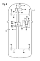
- a vehicle 1 moves according to FIG. 1 in a right lane 2 of a roadway 3.
- the roadway 3 may, as shown, the right lane 2 and a left lane 3 and is laterally delimited by lane lines 4 and 5; a middle lane line 6 separates the two lanes 2 and 7.
- the lane direction Rs of the lane 2 results as a tangent to the limiting lane lines or as an average of these.
- the vehicle 2 is traveling at a vehicle speed v, whose direction Rv is in accordance with FIG. 1 can generally deviate from the track direction Rx. Furthermore, the direction RL of the longitudinal axis of the vehicle 2 may deviate from Rv and Rx.
- the indices x and y refer to the lane 2; the x-direction corresponds to the track direction Rs, the transverse direction y is perpendicular to x.
- v 2 v x 2 + v y 2 .
- v x the longitudinal component of the speed to the track direction R
- v y the lateral velocity.
- the vehicle 1 moves at an intersection angle ⁇ to the track direction Rs.
- vx v • sin ⁇
- vy v • cos ⁇ .
- the lane departure warning control comprises an activation criterion (trigger criterion) K1 and a deactivation criterion K2 for an automatic vehicle dynamics intervention.
- the vehicle 1 has a lane keeping assistance system 11 with a control device 10, wherein the lane keeping assistance system 11 also z. B. can be integrated in a vehicle dynamics control.
- the vehicle dynamics intervention on the vehicle can be an automatic steering intervention at z.
- an electromechanical steering or electric steering EPS, electric power steering
- an automatic brake intervention in particular a one-sided braking intervention or asymmetric braking intervention
- the control device 10 controls directly via vehicle dynamics control signals S1, S2 directly or indirectly to wheel brakes 12 and / or a steering engagement device 15, the z. B. part an electric or electromechanical steering.
- the time-activation criterion K1 of the lane-keeping assistance control is determined by a time-to-time-crossing (TLC) ⁇ until the lane line 4, 5 has been exceeded, according to FIG. 1 thus the right lane line 5.
- TLC time-to-time-crossing
- the lower threshold value Ts is chosen so that it is just below the human reaction time ( moment of shock ) T Reak , but still above the technical realization time T Real T re ⁇ ak > T S > T re ⁇ al .
- FIG. 3 shows an example of a driving scene
- the vehicle 1 still has sufficient distance to the right lane line 5, at time t1, the TLC falls below the threshold value T s , so that subsequently the vehicle dynamics intervention begins.
- the vehicle 1 initially approaches the lane line 5 from the time t1, but according to FIG. 3 with decreasing slope, so that it subsequently moves away from the lane line 5 after reaching a minimum at t2.
- an evaluation of the transverse distance S y can be included in the deactivation criterion, so that S y z. B. greater than 0.2 • b, where b is the lane width of the lane 2. Thus, then two sub-criteria must be met.
- the course of the lane 2 in front of the vehicle 1 is taken into account in order to take into account a non-straight course for determining the remaining travel time (TLC) ⁇ .
- the lane course can z. B. monitored via a camera system 14, 18, z. B. a stereo camera system in the front of the vehicle with a stereo camera 14 and its control device 18, the image signals S3 to the control device 10 outputs.
- map data about the course of the lane 2 or the entire roadway 3 can be used, which are provided by a navigation system 16, which in a known manner a GPS receiver 20 for receiving GPS signals and a map memory 21 and a controller 22 that performs map matching.
- a map matching or a position determination can be made in the map data.
- z. B. the middle lane line 6 may not be located, z. B. on a highway, or even in construction on multi-lane highways. This case can be detected when a determined from camera signals transverse distance, here thus z. B. 2 • b, between the lane lines 4 and 5 is recognized as too large and / or is determined from map and navigation signals that a multi-lane roadway 3 is present.
- the mean lane line 6 can be determined by both lateral lane lines 4, 5 are detected by the stereo camera 14 and from this directly or in consultation with the navigation data, the position of the middle lane 6 is determined.
- step St0 ie when starting the vehicle dynamics control or starting the engine, or even while driving, ie v> 0.
- vehicle dynamics data is continuously recorded via the CAN bus of the vehicle 1, and according to step St2 the remaining travel time (TLC) ⁇ until crossing or reaching one of the lane lines 4, 5 determined.
- step St3 the activation criterion K1 is not met, according to the branch n, the method is again reset before the step St1, and thus the loop of St1 and St2 is continuously run through.
- step St4 is continuously executed in a loop according to branch n2 until, according to branch y2, the deactivation criterion K2 is fulfilled and thus in step St6 the driving dynamics intervention is ended and the method is reset before step St1.
- the control device 10 of the inventive toe holder assistance control has interfaces 10-1 for receiving camera signals S3, driving dynamics signals S4 and navigation signals S5 and an interface 10-2 for outputting the brake control signals S1 and possibly steering control signals S2.
- the interfaces 10-1 and 10-2 can z. B. be formed by the CAN bus.
Landscapes
- Engineering & Computer Science (AREA)
- Transportation (AREA)
- Mechanical Engineering (AREA)
- Automation & Control Theory (AREA)
- Chemical & Material Sciences (AREA)
- Combustion & Propulsion (AREA)
- Traffic Control Systems (AREA)
- Control Of Driving Devices And Active Controlling Of Vehicle (AREA)
- Steering Control In Accordance With Driving Conditions (AREA)
Abstract
Description
Spurhalteassistenz-Systeme mit selbsttätigem Eingriff in die Fahrzeugdynamik bzw. selbsttätiger Spurkorrektur werden auch als eingreifende Spurhalteassistenz-Systeme, LDP (lane departure prevention), LKS (lane keeping system) oder LKAS (lane keeping assistant system) bezeichnet.Lane keeping assistance systems with automatic intervention in vehicle dynamics or automatic lane correction are also referred to as lane-keeping assistance systems, lane departure prevention (LDP), lane keeping systems (LKS) or lane keeping assistant systems (LKAS).
Die Spurhalteassistenz-Systeme detektieren das Fahrzeugumfeld mittels einer Umfeldsensorik und greifen in die Fahrzeugdynamik ein, um ein Verlassen der Fahrspur des Fahrzeugs zu verhindern. Hierbei können unterschiedliche Aktoren des Fahrzeugs angesteuert werden, insbesondere die Fahrzeuglenkung und/oder Bremsen. Selbsttätige Eingriffe in die Fahrzeug-Lenkung sind insbesondere bei einer elektromechanischen Lenkung (EPS, electric power steering), einer Aktivlenkung (AFS, active front steering) oder RWS (rear wheel steering), möglich. Bremseingriffe können insbesondere durch einseitige Bremseingriffe oder asymmetrische Bremseingriffe erfolgen. Durch die Eingriffe in die Fahrzeug-Aktorik wird ein Giermoment um die Fahrzeughochachse aufgeprägt, welches das Fahrzeug zu einer Gierbewegung veranlasst, um das Verlassen der Spur zu verhindern.The lane departure warning systems detect the vehicle environment by means of environment sensors and intervene in the vehicle dynamics to prevent leaving the lane of the vehicle. In this case, different actuators of the vehicle can be controlled, in particular the vehicle steering and / or brakes. Automatic intervention in vehicle steering is possible, in particular, with electromechanical steering (EPS, electric power steering), active steering (AFS, active front steering) or RWS (rear wheel steering). Brake interventions can be carried out in particular by unilateral brake interventions or asymmetric brake interventions. As a result of the intervention in the vehicle actuator system, a yawing moment is imposed about the vehicle vertical axis, which causes the vehicle to yaw to prevent it from leaving the lane.
Hierbei sind LKS-Systeme bekannt, die auf einer kontinuierlichen Stellgröße, insbesondere dem Lenkmoment beruhen und über die gesamte Fahrbahnbreite aktiv sind. Derartige Regelungen können als unangenehm empfunden werden, da die Stellgröße kontinuierlich und unabhängig von der Fahrerintention eingreift. Andere Fahrerassistenzsysteme zielen darauf ab, den Eingriff abhängig vom Überschreiten einer Regelschwelle vorzunehmen. Nachteilig an derartigen Systemen ist jedoch, dass die Regelschwelle typischerweise unabhängig von der Position des Fahrzeugs zur Fahrbahnbegrenzung wirkt und damit bei breiten Fahrbahnen oftmals zu früh greift.In this case, LKS systems are known which are based on a continuous control variable, in particular the steering torque and are active over the entire roadway width. Such regulations can be perceived as unpleasant because the manipulated variable intervenes continuously and independently of the driver intention. Other driver assistance systems aim to perform the intervention depending on exceeding a control threshold. A disadvantage of such systems, however, is that the control threshold is typically independent of the Position of the vehicle to the road boundary acts and thus often attacks too early on wide roads.
Die
Erfindungsgemäß werden ein Verfahren und eine Vorrichtung zur Spurhalteassistenzregelung geschaffen, die einen selbsttätigen Eingriff in die Fahrdynamik beginnen, wenn eine verbleibende Fahrzeit bis zum Kreuzen der begrenzenden Fahrspur-Linie unterschritten wird. Dies kann somit ein Aktivierungskriterium für den Regeleingriff bzw. Eingriff in die Fahrdynamik darstellen.According to the invention, a method and a device for lane keeping assistance control are provided, which start an automatic intervention in the driving dynamics when a remaining travel time is exceeded until the crossing of the limiting lane line. This can thus represent an activation criterion for the control intervention or intervention in the vehicle dynamics.
Somit wird vorteilhafterweise ein inneres Band der Fahrspur des Fahrzeugs geschaffen, in dem keine Fahrdynamikeingriffe der Spurhalteassistenzregelung eingeleitet werden.Thus, advantageously, an inner band of the lane of the vehicle is created in which no driving dynamics interventions of the lane keeping assistance control are initiated.
Ein Deaktivierungskriterium zur Beendigung des selbsttätigen Fahrdynamikeingriffs zielt darauf ab, eine Fahrzeug-Ausrichtung mit der Fahrspur-Richtung zu vergleichen.A deactivation criterion for terminating the automatic vehicle dynamics intervention aims to compare a vehicle orientation with the lane direction.
Die Fahrzeug-Ausrichtung kann hierbei z. B. durch die Fahrtrichtung, d. h. die Richtungsangabe des Geschwindigkeitsvektors des Fahrzeugs, oder durch die Längsachse des Fahrzeugs festgelegt sein. Die Fahrspurrichtung ergibt sich als aktuelle Richtung der Fahrspur und kann z. B. durch eine Tangente an eine Mittellinie der Fahrspur oder eine begrenzende Fahrspurlinie festgelegt werden.The vehicle orientation can be z. B. by the direction of travel, d. H. the direction indication of the speed vector of the vehicle, or be determined by the longitudinal axis of the vehicle. The lane direction results as the current direction of the lane and can, for. B. be determined by a tangent to a center line of the lane or a limiting lane line.
In das Deaktivierungskriterium kann ergänzend zu dem Vergleich der Richtungen auch einen Minimalabstand zu den Fahrspurlinien enthalten sein, um nicht eine zu schnelle nachfolgende Aktivierung zuzulassen. Somit kann das Deaktivierungskriterium durch zwei oder mehr Teilkriterien gebildet werdenIn addition to the comparison of the directions, a minimum distance to the lane lines may also be included in the deactivation criterion so as not to permit too rapid subsequent activation. Thus, the deactivation criterion can be formed by two or more subcriteria
Der Vergleich der Richtungen kann zum einen dahingehend erfolgen, dass bei Parallelität der Fahrzeug-Ausrichtung mit der Fahrspurrichtung das Deaktivierungskriterium erfüllt ist. Weiterhin kann das Deaktivierungskriterium auch erst bei Überschreiten der Parallelität erreicht wird, d. h. wenn der Schnittwinkel zwischen der Fahrzeugrichtung und der Fahrspurrichtung sein Vorzeichen ändert.The comparison of the directions can on the one hand take place in such a way that, when the vehicle alignment is parallel with the lane direction, the deactivation criterion is met. Furthermore, the deactivation criterion can only be reached when the parallelism is exceeded, ie. H. when the intersection angle between the vehicle direction and the lane direction changes its sign.
Erfindungsgemäß werden einige Vorteile erreicht:
- Indem die selbsttätige Fahrzeugregelung nur in einem äußeren Randbereich der Fahrspur eingeleitet wird, ist vorteilhafterweise ein innerer Bereich hierdurch nicht betroffen, so dass in diesem keine den Fahrer störende Gängelung bzw. keine unerwünschten Fahrdynamikeingriffe auftreten. So kann der Fahrer z. B. ungestört in dem inneren Bereich der Fahrspur etwas nach links fahren, um für einen nachfolgenden Überholvorgang an einem größeren vorausfahrenden Fahrzeug vorbei die angrenzende Gegenfahrspur besser einsehen zu können, oder in einer etwas weiter rechts gelegenen Position besser auf Verkehrs- und Hinweisschilder achten zu können.
- By the automatic vehicle control is initiated only in an outer edge region of the lane, advantageously an inner region is not affected by this, so that in this no disturbance disturbing the driver or no unwanted driving dynamics interventions occur. So the driver z. B. drive undisturbed in the inner region of the lane a little to the left to better see the adjacent oncoming lane for a subsequent passing on a larger vehicle ahead, or to pay attention in a slightly further to the right position better on traffic and information signs ,
Hierzu ist die Überprüfung der verbleibenden Fahrzeit vorteilhaft gegenüber z. B. einem reinen Vergleich mit einem Schwellwert für den Querabstand zur seitlich begrenzenden Fahrspur-Linie, da sie z. B. eine Annäherung unter kleinem Winkel bis nahe an die Fahrspur-Linie zulässt, ohne bereits eine Aktivierung einzuleiten, wenn der Fahrer bewusst den vorausliegenden Verkehrsraum einsehen will.For this purpose, the review of the remaining travel time is advantageous over z. B. a pure comparison with a threshold for the transverse distance to the laterally limiting lane line, as they are z. B. allows approaching at a small angle to close to the lane line without already initiate an activation when the driver intentionally wants to see the forward traffic space.
Indem die Deaktivierung des selbsttätigen Fahrzeugeingriffs nicht auf einen Querabstand bzw. das Verlassen eines seitlichen Randbereichs gerichtet ist, sondern auf eine hinreichende Gierbewegung des Fahrzeugs zumindest parallel zur Fahrspurrichtung, kann vermieden werden, dass in dem Randbereich fortlaufend selbsttätige Fahrdynamik-Regeleingriffe durchgeführt und nach Beendigung bald wieder vorgenommen werden.By the deactivation of the automatic vehicle intervention is not directed to a transverse distance or leaving a lateral edge region, but on a sufficient yawing motion of the vehicle at least parallel to the lane direction, it can be avoided that in the edge region continuously automatic driving dynamics control operations carried out and soon after termination be made again.
Indem das Deaktivierungskriterium vorteilhafterweise verlangt, dass der Schnittwinkel der Richtungen einen Vorzeichenwechsel ausführt und somit das Fahrzeug über die Parallelität hinaus in die Gegenrichtung giert bzw. schwenkt, können derartige fortlaufend wiedereinsetzenden Regelungen besonders gut unterdrückt werden.Since the deactivation criterion advantageously requires that the intersection angle of the directions perform a change of sign and thus yaw the vehicle beyond parallelism in the opposite direction, such continuous re-establishing controls can be suppressed particularly well.
Dem liegt auch die Erkenntnis zu Grunde, dass insbesondere auch in Kurvensituationen ein derartiges Übergieren eher vorteilhaft ist. In einer einfachen Kurve wird ein Unterschreiten des Minimalabstandes eher an der kurvenäußeren Fahrspurlinie auftreten, in einer Linkskurve somit an der rechten Fahrspurlinie. Ein Fahrdynamikeingriff dahingehend, dass die Ausrichtung des Fahrzeugs stärker in die Kurve hinein erfolgt, hilft hierbei, das Fahrzeug nachfolgend weiter von der äußeren Fahrspurlinie weg zu führen.This is also based on the realization that such a yawing is more advantageous, especially in curve situations. In a simple curve, a drop below the minimum distance will occur more on the outside lane line, in a left turn thus on the right lane line. A driving dynamics intervention in that the orientation of the vehicle is more pronounced in the curve hereby helps to lead the vehicle further away from the outer lane line.
Eine nicht eingezeichnete mittlere Fahrspur-Linie, die nicht in der Fahrbahn eingezeichnet ist, kann erfindungsgemäß aus Kamerasignalen und gegebenenfalls Navigationssignalen ermittelt werden. Hierbei kann dieser Fall erkannt werden, wenn ein aus Kamerasignalen ermittelter Querabstand zwischen Fahrspurlinien als zu groß erkannt wird und/oder aus Karten- und Navigationssignalen ermittelt wird, dass eine mehrspurige Fahrbahn vorliegt.A non-drawn average lane line, which is not drawn in the road, can be determined according to the invention from camera signals and, where appropriate, navigation signals. In this case, this case can be detected when a determined from camera signals transverse distance between lane lines is recognized as too large and / or is determined from map and navigation signals that a multi-lane road is present.
- Fig. 1Fig. 1
- zeigt eine Fahrsituation eines Fahrzeugs auf einer Fahrbahn bei Durchführung eines Verfahrens gemäß einer Ausführungsform der Erfindung;shows a driving situation of a vehicle on a roadway when carrying out a method according to an embodiment of the invention;
- Fig. 2Fig. 2
-
zeigt das Fahrzeug aus
Figur 1 in vergrößerter Darstellung;shows the vehicleFIG. 1 in an enlarged view; - Fig. 3Fig. 3
- ein Diagramm des zeitlichen Verlaufs der jeweils aktuellen verbleibenden Fahrzeit;a diagram of the time course of the current remaining travel time;
- Fig. 4Fig. 4
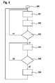
- ein Flussdiagramm eines erfindungsgemäßen Verfahrens.a flowchart of a method according to the invention.
Ein Fahrzeug 1 fährt gemäß
Die Spur-Richtung Rs der Fahrspur 2 ergibt sich als Tangente an den begrenzenden Fahrspur-Linien oder als Mittelwert von diesen.The lane direction Rs of the
Das Fahrzeug 2 fährt mit einer Fahrgeschwindigkeit v, deren Richtung Rv gemäß
Gemäß
Für die Zusammensetzung der Geschwindigkeit v gilt: ![]()
wobei vx die Längskomponente der Geschwindigkeit zur Spurrichtung R und vy die Quergeschwindigkeit darstellt. Das Fahrzeug 1 fährt unter einem Schnittwinkel ϕ zur Spurrichtung Rs. Somit ergibt sich vx = v • sin ϕ und vy = v • cos ϕ.For the composition of the velocity v: ![]()
where v x represents the longitudinal component of the speed to the track direction R and v y represents the lateral velocity. The
Die Spurhalteassistenz-Regelung umfasst ein Aktivierungskriterium (Auslösekriterium) K1 und ein Deaktivierungskriterium K2 für einen selbsttätigen Fahrdynamikeingriff.The lane departure warning control comprises an activation criterion (trigger criterion) K1 and a deactivation criterion K2 for an automatic vehicle dynamics intervention.
Das Fahrzeug 1 weist ein Spurhalte-Assistenzsystem 11 mit einer Steuereinrichtung 10 auf, wobei das Spurhalte-Assistenzsystem 11 auch z. B. in einer Fahrdynamikregelung integriert sein kann.The
Der Fahrdynamik-Eingriff am Fahrzeug kann einen selbsttätigen Lenkeingriff bei z. B. einer elektromechanischen Lenkung oder elektrischen Lenkung (EPS, electric power steering), und/oder durch einen selbsttätigen Bremseingriff, insbesondere einen einseitigen Bremseingriff oder asymmetrischen Bremseingriff umfassen. Zur Durchführung eines Fahrdynamik-Eingriffs steuert die Steuereinrichtung 10 entsprechend über Fahrdynamik- Steuersignale S1, S2 direkt oder indirekt Radbremsen 12 und/oder eine Lenk- Eingriffseinrichtung 15 an, die z. B. Teil einer elektrischen oder elektromechanischen Lenkung ist. Ergänzend kann währendThe vehicle dynamics intervention on the vehicle can be an automatic steering intervention at z. As an electromechanical steering or electric steering (EPS, electric power steering), and / or by an automatic brake intervention, in particular a one-sided braking intervention or asymmetric braking intervention include. To carry out a vehicle dynamics intervention, the
Das zeitliche Aktivierungskriterium K1 der Spurhalteassistenz -Regelung wird durch eine verbleibende Fahrzeit (time to line crossing, TLC) τ bis zur Überschreitung einer Fahrspur-Linie 4, 5 bestimmt, gemäß
Die Zeit τ bis zum Überschreiten der Fahrspur-Linie 5 ergibt sich somit zu: 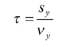
wobei sy z. B. als Querabstand der äußeren physikalischen Begrenzung des Fahrzeugs 1 zur Fahrspur-Linie 5 definiert ist.The time τ until the
where s y z. B. is defined as the transverse distance of the outer physical boundary of the
Als Auslösekriterium K1 wird nun die verbleibende Fahrzeit τ mit einem unteren Schwellwert Ts verglichen. Es gilt somit 
d. h. die verbleibende Fahrzeit (time to line crossing) τ erreicht oder unterschreitet den unteren Schwellwert Ts.As a triggering criterion K1 now the remaining travel time τ is compared with a lower threshold Ts. It therefore applies
ie the remaining time to time (time to line crossing) τ reaches or falls below the lower threshold Ts.
Hierzu wird der untere Schwellwert Ts so gewählt, dass er sich gerade unterhalb der menschlichen Reaktionszeit (Schrecksekunde) TReak befindet, aber noch oberhalb der technischen Realisierungszeit TReal 
Am Beispiel der Funktionsausprägung über die Radbremsen 12 ist dies somit die Druckaufbauzeit plus der benötigen Zeit zum Gieren bzw. Richtungsändern.Using the example of the functional expression on the
Zum Zeitpunkt t0 hat das Fahrzeug 1 noch hinreichenden Abstand zur rechten Fahrspurlinie 5, zum Zeitpunkt t1 unterschreitet die TLC den Schwellwert Ts, so dass nachfolgend der Fahrdynamik-Eingriff beginnt.At time t0, the
Somit nähert sich das Fahrzeug 1 ab dem Zeitpunkt t1 zwar zunächst noch weiter der Fahrspurlinie 5, jedoch gemäß
Zur Deaktivierung des Fahrdynamik-Eingriffs ist ein Deaktivierungskriterium K2 vorgesehen. Dieses Deaktivierungskriterium K2 enthält eine Überprüfung, die gemäß den Alternativen K2a oder K2b ausgebildet sein kann:
- K2a: Ist die Fahrtrichtung Rv (Vektor von v) und/oder die Fahrzeugrichtung RL (Richtung der Längsachse) wieder parallel zur Spurrichtung Rs, ?
- K2b: Ist diese Parallelität zwischen einerseits der Fahrtrichtung Rv (Vektor von v) und/oder der Fahrzeugrichtung RL (Richtung der Längsachse) und andererseits der Spurrichtung Rs bereits überschritten?
- K2 kann somit gemäß der Variante K2a auf reine Parallelität von Rv und Rs ausgerichtet sein.
- Bei Parallelität der Fahrtrichtung Rv mit der Spurrichtung R somit wird dann die verbleibende Fahrzeit τ unendlich, wie in Zeitpunkt t3 in dem Diagramm der
Figur 3 . Der Schnittwinkel ϕ wird Null.
- K2a: Is the direction of travel Rv (vector of v) and / or the vehicle direction R L (direction of the longitudinal axis) again parallel to the track direction Rs,?
- K2b: Has this parallelism between the direction of travel Rv (vector of v) and / or the vehicle direction R L (direction of the longitudinal axis) and the track direction Rs already been exceeded?
- K2 can thus be aligned according to the variant K2a on pure parallelism of Rv and Rs.
- In parallelism of the direction of travel Rv with the track direction R thus the remaining travel time τ is then infinite, as at time t3 in the diagram of
FIG. 3 , The cutting angle φ becomes zero.
Wenn gemäß der Variante K2b ein Überschreiten der Parallelität überprüft wird, wird somit überprüft, ob der Schnittwinkel ϕ sein Vorzeichen ändert.If according to the variant K2b an exceeding of the parallelism is checked, it is thus checked whether the intersection angle φ changes its sign.
Ergänzend kann in das Deaktivierungskriterium auch eine Bewertung des Querabstandes Sy einbezogen werden, so dass Sy z. B. größer 0,2 • b ist, wobei b die Fahrspurbreite der Fahrspur 2 ist. Somit müssen dann zwei Teilkriterien erfüllt sein.In addition, an evaluation of the transverse distance S y can be included in the deactivation criterion, so that S y z. B. greater than 0.2 • b, where b is the lane width of the
Vorteilhafterweise wird der Verlauf der Fahrspur 2 vor dem Fahrzeug 1 berücksichtigt, um einen nicht-geraden Verlauf zur Ermittlung der verbleibenden Fahrzeit (TLC) τ zu berücksichtigen. Der Fahrspurverlauf kann z. B. über ein Kamerasystem 14, 18 überwacht werden, z. B. ein Stereo-Kamerasystem im Frontbereich des Fahrzeugs mit einer Stereokamera 14 und deren Steuereinrichtung 18, die Bildsignale S3 an die Steuereinrichtung 10 ausgibt. Ergänzend oder alternativ können Kartendaten über den Verlauf der Fahrspur 2 bzw. der gesamten Fahrbahn 3 herangezogen werden, die von einem Navigationssystem 16 zur Verfügung gestellt werden, das in bekannter Weise einen GPS-Empfänger 20 zum Empfangen von GPS-Signalen und einen Kartenspeicher 21 sowie eine Steuereinrichtung 22 aufweist, die ein map-Matching durchführt. Somit kann ein map-Matching bzw. eine Positionsbestimmung in den Kartendaten erfolgen.Advantageously, the course of the
Verfahren zur Ermittlung der verbleibenden Fahrtzeit τ bzw. Time to Line Crossing aufgrund von Kartendaten bei z. B. gekrümmter Fahrspur 2 sind als solche bekannt.Method for determining the remaining travel time τ or time to line crossing based on map data at z. B. curved
Grundsätzlich kann z. B. die mittlere Fahrspur-Linie 6 nicht eingezeichnet sein, z. B. bei einer Landstraße, oder auch bei Bauarbeiten an mehrspurigen Schnellstraßen. Dieser Fall kann erkannt werden, wenn ein aus Kamerasignalen ermittelter Querabstand, hier somit z. B. 2 • b, zwischen den Fahrspurlinien 4 und 5 als zu groß erkannt wird und/oder aus Karten- und Navigationssignalen ermittelt wird, dass eine mehrspurige Fahrbahn 3 vorliegt. In diesem Fall kann die mittlere Fahrspur-Linie 6 ermittelt werden, indem beide seitlichen Fahrspur-Linien 4, 5 von der Stereokamera 14 erfasst werden und hieraus direkt oder unter Hinzuziehung der Navigationsdaten die Position der mittleren Fahrspur 6 ermittelt wird.Basically, z. B. the middle lane line 6 may not be located, z. B. on a highway, or even in construction on multi-lane highways. This case can be detected when a determined from camera signals transverse distance, here thus z. B. 2 • b, between the
Das erfindungsgemäße Verfahren startet somit gemäß
Falls das Aktivierungskriterium K1 erfüllt ist, d. h. τ ≤ Ts erfüllt ist, wird gemäß Verzweigung y1 nachfolgend in Schritt St4 die Fahrdynamik-Regelung mit aktivem Fahrdynamik-Eingriff durch z. B. Ausgabe der Fahrdynamik- Steuersignale S1, S2 für einen Bremseingriff oder Lenkeingriff gestartet und fortlaufend gemäß Schritt St5 überprüft, ob das Deaktivierungskriterium K2 erfüllt ist. Solange K2 nicht erfüllt ist, wird gemäß Verzweigung n2 in einer Schleife fortlaufend der Schritt St4 durchgeführt, bis gemäß der Verzweigung y2 das Deaktivierungskriterium K2 erfüllt ist und somit in Schritt St6 der Fahrdynamikeingriff beendet wird und das Verfahren vor den Schritt St1 zurückgesetzt wird.If the activation criterion K1 is satisfied, ie τ ≦ T s is satisfied, according to branch y1, the vehicle dynamics control with active vehicle dynamics intervention by z. B. output of the vehicle dynamics control signals S1, S2 for a braking intervention or steering intervention started and continuously checked according to step St5, if the deactivation criterion K2 is met. As long as K2 is not satisfied, step St4 is continuously executed in a loop according to branch n2 until, according to branch y2, the deactivation criterion K2 is fulfilled and thus in step St6 the driving dynamics intervention is ended and the method is reset before step St1.
Die Steuereinrichtung 10 der erfindungsgemäßen Spurhalter-Assistenzregelung weist Schnittstellen 10-1 zur Aufnahme von Kamerasignalen S3, Fahrdynamik-signalen S4 und Navigationssignalen S5 sowie eine Schnittstelle 10-2 zur Ausgabe der Brems-Steuersignale S1 und gegebenenfalls Lenksteuersignale S2 auf. Die Schnittstellen 10-1 und 10-2 können z. B. durch den CAN-Bus gebildet werden.The
Claims (8)
wobei überprüft wird, ob ein Aktivierungskriterium für einen selbsttätigen Fahrdynamikeingriff erfüllt ist und bei Erfüllen des Aktivierungskriteriums Steuersignale (S1, S2) für den Fahrdynamikeingriff ausgegeben werden, dadurch gekennzeichnet, dass
als Aktivierungskriterium eine verbleibende Fahrzeit () zum Kreuzen oder Erreichen einer seitlichen Fahrspurlinie (4, 5) ermittelt und mit einem Schwellwert (Ts) verglichen wird, und
während des selbsttätigen Fahrdynamikeingriffs ein Deaktivierungskriterium (K2) zur Beendigung des selbsttätigen Fahrdynamikeingriffs überprüft wird, wobei das Deaktivierungskriterium (K2) einen Vergleich einer Fahrzeug-Ausrichtung (Rv, RL) mit einer Fahrspur-Richtung (Rs) enthält.Lane Keeping Assistance Method for a Vehicle (1) Running on a Lane (2)
wherein it is checked whether an activation criterion for an automatic driving dynamics intervention is fulfilled and when the activation criterion control signals (S1, S2) are output for the vehicle dynamics intervention, characterized in that
as the activation criterion a remaining travel time () for crossing or reaching a lateral lane line (4, 5) is determined and compared with a threshold value (T s ), and
during the automatic vehicle dynamics intervention, a deactivation criterion (K2) for ending the automatic vehicle dynamics intervention is checked, wherein the deactivation criterion (K2) contains a comparison of a vehicle orientation (Rv, RL) with a lane direction (Rs).
wobei die Steuereinrichtung überprüft, ob ein Aktivierungskriterium (K1) für einen selbsttätigen Fahrdynamikeingriff erfüllt ist und bei Erfüllen des Aktivierungskriteriums (K1) Steuersignale (S1, S2) für den Fahrdynamikeingriff ausgegeben werden,
dadurch gekennzeichnet, dass
die Steuereinrichtung (10) als Aktivierungskriterium eine verbleibende Fahrzeit () zum Kreuzen oder Erreichen einer seitlichen Fahrspurlinie (4, 5) ermittelt und mit einem Schwellwert (Ts) vergleicht und während des Fahrdynamikeingriffs ein Deaktivierungskriterium (K2) zur Beendigung des selbsttätigen Fahrdynamikeingriffs überprüft, wobei das Deaktivierungskriterium (K2) einen Vergleich einer Fahrzeug-Ausrichtung (Rv, RL) mit einer Fahrspur-Richtung (Rs) aufweist.Control device (10) for lane departure control, in particular for carrying out a method according to one of the preceding claims, wherein the control device (10) interfaces (10-1, 10-2) for receiving driving dynamics signals (S2) and for outputting control signals (S1, S2) for changing the driving dynamics of the vehicle (1),
wherein the control device checks whether an activation criterion (K1) for an automatic driving dynamics intervention is fulfilled and when fulfilling the activation criterion (K1) control signals (S1, S2) are output for the vehicle dynamics intervention,
characterized in that
the control device (10) determines as activation criterion a remaining travel time () for crossing or reaching a lateral lane line (4, 5) and compares it with a threshold value (T s ) and checks a deactivation criterion (K2) for termination of the automatic vehicle dynamics intervention during the vehicle dynamics intervention, wherein the deactivation criterion (K2) comprises a comparison of a vehicle orientation (Rv, RL) with a lane direction (Rs).
Applications Claiming Priority (1)
| Application Number | Priority Date | Filing Date | Title |
|---|---|---|---|
| DE102011084611A DE102011084611A1 (en) | 2011-10-17 | 2011-10-17 | Method and apparatus for lane departure control |
Publications (2)
| Publication Number | Publication Date |
|---|---|
| EP2583875A2 true EP2583875A2 (en) | 2013-04-24 |
| EP2583875A3 EP2583875A3 (en) | 2014-09-17 |
Family
ID=46800047
Family Applications (1)
| Application Number | Title | Priority Date | Filing Date |
|---|---|---|---|
| EP12181865.2A Withdrawn EP2583875A3 (en) | 2011-10-17 | 2012-08-27 | Method and device for controlling a lane departure warning system |
Country Status (4)
| Country | Link |
|---|---|
| US (1) | US8788136B2 (en) |
| EP (1) | EP2583875A3 (en) |
| CN (1) | CN103043054A (en) |
| DE (1) | DE102011084611A1 (en) |
Cited By (1)
| Publication number | Priority date | Publication date | Assignee | Title |
|---|---|---|---|---|
| WO2017197819A1 (en) * | 2016-05-16 | 2017-11-23 | 乐视控股(北京)有限公司 | Vehicle driving regulation prompting method and apparatus, and electronic device |
Families Citing this family (25)
| Publication number | Priority date | Publication date | Assignee | Title |
|---|---|---|---|---|
| KR101814601B1 (en) * | 2010-12-09 | 2018-01-04 | 삼성전자주식회사 | System and method for safe taxi service |
| KR101541483B1 (en) * | 2014-01-03 | 2015-08-03 | 현대모비스(주) | System for monitoring change of a traffic lane andcontrol method thereof |
| JP5936281B2 (en) * | 2014-03-31 | 2016-06-22 | 富士重工業株式会社 | Vehicle lane departure prevention control device |
| CN103978978B (en) * | 2014-05-26 | 2016-06-22 | 武汉理工大学 | Track keeping method based on Inverse projection |
| EP2949548B1 (en) * | 2014-05-27 | 2018-07-11 | Volvo Car Corporation | Lane keeping suppressing system and method |
| KR20160066297A (en) * | 2014-12-02 | 2016-06-10 | 현대모비스 주식회사 | Apparatus and method for controlling start-up for lane keeping assist system |
| FR3038281B1 (en) | 2015-07-03 | 2017-07-21 | Peugeot Citroen Automobiles Sa | METHOD FOR ASSISTING A DRIVER PROVIDING A DRIVING POSITION ACCORDING TO A CONTEXT OF DRIVING |
| FR3041778B1 (en) * | 2015-09-29 | 2018-08-17 | Psa Automobiles Sa. | MOTOR VEHICLE RECOVERY ASSISTING METHOD |
| US9443426B1 (en) | 2015-11-13 | 2016-09-13 | Byron Paul Formwalt | Method and device for sensing traffic flow and notifying motor vehicle drivers of the same |
| DE102016202590A1 (en) * | 2016-02-19 | 2017-09-07 | Robert Bosch Gmbh | Method and device for operating an automated motor vehicle |
| KR101819003B1 (en) * | 2016-04-07 | 2018-01-16 | 엘지전자 주식회사 | Driver assistance apparatus and Vehicle |
| FR3050423B1 (en) | 2016-04-25 | 2020-05-01 | Peugeot Citroen Automobiles Sa | AUTOMATED DRIVING SYSTEM FOR A MOTOR VEHICLE WITH AN ADVANCED VISUAL COMMUNICATION INTERFACE |
| US10160459B2 (en) | 2017-03-22 | 2018-12-25 | Ford Global Technologies, Llc | Vehicle lane direction detection |
| JP6898636B2 (en) * | 2017-03-30 | 2021-07-07 | 株式会社Subaru | Vehicle travel control device |
| CN106971593A (en) * | 2017-04-01 | 2017-07-21 | 深圳市元征科技股份有限公司 | Lane recognition method and device |
| US20190212747A1 (en) * | 2017-08-30 | 2019-07-11 | Continental Automotive Systems, Inc. | Lane Marker Signal Improvement through Mapped Geo-Referenced Lane Boundaries |
| SE541795C2 (en) * | 2017-09-22 | 2019-12-17 | Sentient Ip Ab | Method and system for controlling vehicle lane holding |
| FR3071800B1 (en) | 2017-09-29 | 2021-04-02 | Psa Automobiles Sa | DRIVING ASSISTANCE PROCESS OF A VEHICLE IN THE EVENT OF A FAILURE OF A NETWORK AND ASSOCIATED SYSTEM |
| CN108345855B (en) * | 2018-02-08 | 2020-08-18 | 青岛平行智能产业管理有限公司 | Lane line pressing detection method and system |
| DE102018203287B4 (en) * | 2018-03-06 | 2024-03-07 | Audi Ag | Method and system for operating a lane keeping assistance device of a motor vehicle |
| US10723359B2 (en) * | 2018-04-12 | 2020-07-28 | Rivian Ip Holdings, Llc | Methods, systems, and media for controlling access to vehicle features |
| EP3567565A1 (en) * | 2018-05-09 | 2019-11-13 | Volkswagen AG | Apparatus, method, computer program, base station and vehicle for providing information related to an approaching vehicle |
| WO2020001758A1 (en) * | 2018-06-27 | 2020-01-02 | Volvo Truck Corporation | Method and system for controlling steering of a vehicle |
| CN109580243A (en) * | 2018-11-23 | 2019-04-05 | 中汽研(天津)汽车工程研究院有限公司 | A kind of real vehicle lane keeps the assessment method of auxiliary system performance |
| CN112477847B (en) * | 2020-12-11 | 2022-09-27 | 清华大学苏州汽车研究院(吴江) | Traffic jam auxiliary control method and system |
Citations (1)
| Publication number | Priority date | Publication date | Assignee | Title |
|---|---|---|---|---|
| DE102008040627A1 (en) | 2008-07-23 | 2010-02-04 | Robert Bosch Gmbh | Method for regulating or controlling steering assistance system for vehicle, involves calculating convergence at peripheral object, where convergence is adapted depending on engaging free area or steering engagement |
Family Cites Families (17)
| Publication number | Priority date | Publication date | Assignee | Title |
|---|---|---|---|---|
| JP3690283B2 (en) * | 2001-01-18 | 2005-08-31 | 日産自動車株式会社 | Lane tracking control device |
| DE10251357A1 (en) * | 2002-11-05 | 2004-05-13 | Daimlerchrysler Ag | Automatic operating method for automobile trafficator display with evaluation of data for identification of turning or lane changing maneuver |
| WO2005037592A1 (en) * | 2003-09-23 | 2005-04-28 | Daimlerchrysler Ag | Method and device for recognising lane changing operations for a motor vehicle |
| JP3900162B2 (en) * | 2004-02-09 | 2007-04-04 | 日産自動車株式会社 | VEHICLE DRIVE OPERATION ASSISTANCE DEVICE AND VEHICLE WITH VEHICLE DRIVE OPERATION ASSISTANCE DEVICE |
| DE102004024692A1 (en) * | 2004-05-19 | 2005-12-15 | Daimlerchrysler Ag | Motor vehicle driver assistance method for keeping to lane, by automatically generating steering wheel torque when lane is left and determining steering wheel angle variation |
| JP4291741B2 (en) * | 2004-06-02 | 2009-07-08 | トヨタ自動車株式会社 | Lane departure warning device |
| DE102004047889A1 (en) * | 2004-10-01 | 2006-04-06 | Robert Bosch Gmbh | Driver supporting process, involves outputting warning of driver in predetermined situation, and warning driver depending on history of tracing performance of driver and/or performance tracking by driver |
| JP4534754B2 (en) * | 2004-12-21 | 2010-09-01 | 日産自動車株式会社 | Lane departure prevention device |
| JP3912416B2 (en) * | 2005-05-31 | 2007-05-09 | トヨタ自動車株式会社 | Vehicle departure prevention control device |
| US7561032B2 (en) * | 2005-09-26 | 2009-07-14 | Gm Global Technology Operations, Inc. | Selectable lane-departure warning system and method |
| DE102005048014A1 (en) * | 2005-10-07 | 2007-04-12 | Robert Bosch Gmbh | Driver assistance system |
| DE102006056094A1 (en) * | 2006-11-28 | 2008-05-29 | Robert Bosch Gmbh | Driver assistance system with presence monitoring |
| WO2008091565A1 (en) * | 2007-01-23 | 2008-07-31 | Valeo Schalter & Sensoren Gmbh | Method and system for universal lane boundary detection |
| DE102007020280A1 (en) * | 2007-04-30 | 2008-11-06 | Robert Bosch Gmbh | Method and device for controlling a driver assistance system |
| DE102008040626A1 (en) | 2008-07-23 | 2010-03-11 | Robert Bosch Gmbh | Method for determining the injected fuel mass of a single injection and apparatus for carrying out the method |
| KR101163446B1 (en) * | 2009-03-18 | 2012-07-18 | 기아자동차주식회사 | A lane departure warning system using a virtual lane and a system according to the same |
| DE102010010489A1 (en) * | 2010-03-06 | 2011-10-06 | Continental Teves Ag & Co. Ohg | Lane keeping system for motor vehicle, has lane detection system for detecting and determining lanes in front of vehicle, and vehicle position determination system |
-
2011
- 2011-10-17 DE DE102011084611A patent/DE102011084611A1/en active Pending
-
2012
- 2012-08-27 EP EP12181865.2A patent/EP2583875A3/en not_active Withdrawn
- 2012-10-15 CN CN2012103891032A patent/CN103043054A/en active Pending
- 2012-10-17 US US13/654,046 patent/US8788136B2/en active Active
Patent Citations (1)
| Publication number | Priority date | Publication date | Assignee | Title |
|---|---|---|---|---|
| DE102008040627A1 (en) | 2008-07-23 | 2010-02-04 | Robert Bosch Gmbh | Method for regulating or controlling steering assistance system for vehicle, involves calculating convergence at peripheral object, where convergence is adapted depending on engaging free area or steering engagement |
Cited By (1)
| Publication number | Priority date | Publication date | Assignee | Title |
|---|---|---|---|---|
| WO2017197819A1 (en) * | 2016-05-16 | 2017-11-23 | 乐视控股(北京)有限公司 | Vehicle driving regulation prompting method and apparatus, and electronic device |
Also Published As
| Publication number | Publication date |
|---|---|
| US8788136B2 (en) | 2014-07-22 |
| CN103043054A (en) | 2013-04-17 |
| DE102011084611A1 (en) | 2013-04-18 |
| US20130096767A1 (en) | 2013-04-18 |
| EP2583875A3 (en) | 2014-09-17 |
Similar Documents
| Publication | Publication Date | Title |
|---|---|---|
| EP2583875A2 (en) | Method and device for controlling a lane departure warning system | |
| DE102012215562B4 (en) | Method for determining an avoidance trajectory for a motor vehicle and safety device or safety system | |
| DE102010042440B4 (en) | Method and device for setting an engagement torque of a steering assistance system | |
| EP3079957B1 (en) | Method for regulating driving stability | |
| DE102012203673A1 (en) | Safety device for a motor vehicle and method for operating a motor vehicle | |
| EP2374695B1 (en) | Method and operation of a tracking assistance system for multi-lane turning in a motor vehicle and motor vehicle | |
| DE102006027325A1 (en) | Lane departure warning with lane change function | |
| EP2170671A1 (en) | Method for automatically correcting a state variable of a vehicle | |
| WO2014135570A1 (en) | Driver assistance system for assisting the drive of a motor vehicle when leaving a determined lane | |
| DE102014012781B4 (en) | Lane change assistant, associated method of operation and motor vehicle | |
| DE102010028109A1 (en) | Method for improving the driving stability of a vehicle | |
| DE102013219023A1 (en) | Method and device for assisting a driver of a vehicle when changing lanes | |
| WO2012119596A1 (en) | Method for the predictive display of an evasive maneuver | |
| EP3177505B1 (en) | Provision of driving instructions during a parking manoeuvre | |
| DE102015205673A1 (en) | Method for operating a brake assistant in a motor vehicle | |
| DE102012206211A1 (en) | Method and device for determining a lane adjustment parameter for a lane keeping system of a vehicle and method and device for tracking a vehicle | |
| DE112018002480T5 (en) | VEHICLE CONTROL DEVICE | |
| DE102016221905A1 (en) | Bottleneck assistance system and assistance procedure in a motor vehicle | |
| WO2020048651A1 (en) | Method and device for making safe an overtaking procedure for a vehicle approaching a bicycle | |
| DE102005005412B4 (en) | Device and method for avoiding oncoming traffic accidents of a vehicle after a rear impact | |
| DE102007054095A1 (en) | Driver assistance system for motor vehicles | |
| DE102006052469A1 (en) | Driver assistance system | |
| DE102010060300A1 (en) | Method for detecting danger situation of vehicle and response for elimination of danger situation, involves determining vehicle environment and feeding jolt in transverse direction of vehicle in travel direction | |
| EP2279923A2 (en) | Method for supporting a driver of a motor vehicle during a skid and motor vehicle | |
| DE102018215509A1 (en) | Method and device for operating an at least partially automated first vehicle |
Legal Events
| Date | Code | Title | Description |
|---|---|---|---|
| PUAI | Public reference made under article 153(3) epc to a published international application that has entered the european phase |
Free format text: ORIGINAL CODE: 0009012 |
|
| AK | Designated contracting states |
Kind code of ref document: A2 Designated state(s): AL AT BE BG CH CY CZ DE DK EE ES FI FR GB GR HR HU IE IS IT LI LT LU LV MC MK MT NL NO PL PT RO RS SE SI SK SM TR |
|
| AX | Request for extension of the european patent |
Extension state: BA ME |
|
| RIC1 | Information provided on ipc code assigned before grant |
Ipc: B62D 15/02 20060101ALI20140423BHEP Ipc: B60W 30/12 20060101AFI20140423BHEP |
|
| PUAL | Search report despatched |
Free format text: ORIGINAL CODE: 0009013 |
|
| AK | Designated contracting states |
Kind code of ref document: A3 Designated state(s): AL AT BE BG CH CY CZ DE DK EE ES FI FR GB GR HR HU IE IS IT LI LT LU LV MC MK MT NL NO PL PT RO RS SE SI SK SM TR |
|
| AX | Request for extension of the european patent |
Extension state: BA ME |
|
| RIC1 | Information provided on ipc code assigned before grant |
Ipc: B60W 30/12 20060101AFI20140808BHEP Ipc: B62D 15/02 20060101ALI20140808BHEP |
|
| STAA | Information on the status of an ep patent application or granted ep patent |
Free format text: STATUS: THE APPLICATION IS DEEMED TO BE WITHDRAWN |
|
| 18D | Application deemed to be withdrawn |
Effective date: 20150303 |