EP2583811B2 - Method for quantifying process fluctuations in the injection process of a injection moulding machine - Google Patents
Method for quantifying process fluctuations in the injection process of a injection moulding machine Download PDFInfo
- Publication number
- EP2583811B2 EP2583811B2 EP12006404.3A EP12006404A EP2583811B2 EP 2583811 B2 EP2583811 B2 EP 2583811B2 EP 12006404 A EP12006404 A EP 12006404A EP 2583811 B2 EP2583811 B2 EP 2583811B2
- Authority
- EP
- European Patent Office
- Prior art keywords
- injection
- function
- transformation parameter
- fluctuations
- pressure
- Prior art date
- Legal status (The legal status is an assumption and is not a legal conclusion. Google has not performed a legal analysis and makes no representation as to the accuracy of the status listed.)
- Active
Links
- 238000000034 method Methods 0.000 title claims description 143
- 230000008569 process Effects 0.000 title claims description 105
- 238000002347 injection Methods 0.000 title claims description 96
- 239000007924 injection Substances 0.000 title claims description 96
- 238000001746 injection moulding Methods 0.000 title claims description 42
- 230000009466 transformation Effects 0.000 claims description 60
- 238000005259 measurement Methods 0.000 claims description 33
- 239000000155 melt Substances 0.000 claims description 13
- 238000006073 displacement reaction Methods 0.000 claims description 8
- 230000001105 regulatory effect Effects 0.000 claims description 2
- 238000013459 approach Methods 0.000 description 3
- 239000008187 granular material Substances 0.000 description 3
- 230000008901 benefit Effects 0.000 description 2
- 230000008859 change Effects 0.000 description 2
- 230000006835 compression Effects 0.000 description 2
- 238000007906 compression Methods 0.000 description 2
- 238000001816 cooling Methods 0.000 description 2
- 230000000694 effects Effects 0.000 description 2
- 239000011159 matrix material Substances 0.000 description 2
- 238000012856 packing Methods 0.000 description 2
- 238000012545 processing Methods 0.000 description 2
- 238000011002 quantification Methods 0.000 description 2
- 241000237858 Gastropoda Species 0.000 description 1
- 230000005540 biological transmission Effects 0.000 description 1
- 230000003111 delayed effect Effects 0.000 description 1
- 230000001419 dependent effect Effects 0.000 description 1
- 238000010586 diagram Methods 0.000 description 1
- 238000010438 heat treatment Methods 0.000 description 1
- 238000012417 linear regression Methods 0.000 description 1
- 239000000463 material Substances 0.000 description 1
- 239000012528 membrane Substances 0.000 description 1
- 238000004886 process control Methods 0.000 description 1
- 238000010008 shearing Methods 0.000 description 1
- 239000000243 solution Substances 0.000 description 1
- 238000000844 transformation Methods 0.000 description 1
Images


Classifications
-
- B—PERFORMING OPERATIONS; TRANSPORTING
- B29—WORKING OF PLASTICS; WORKING OF SUBSTANCES IN A PLASTIC STATE IN GENERAL
- B29C—SHAPING OR JOINING OF PLASTICS; SHAPING OF MATERIAL IN A PLASTIC STATE, NOT OTHERWISE PROVIDED FOR; AFTER-TREATMENT OF THE SHAPED PRODUCTS, e.g. REPAIRING
- B29C45/00—Injection moulding, i.e. forcing the required volume of moulding material through a nozzle into a closed mould; Apparatus therefor
- B29C45/17—Component parts, details or accessories; Auxiliary operations
- B29C45/76—Measuring, controlling or regulating
- B29C45/766—Measuring, controlling or regulating the setting or resetting of moulding conditions, e.g. before starting a cycle
-
- B—PERFORMING OPERATIONS; TRANSPORTING
- B29—WORKING OF PLASTICS; WORKING OF SUBSTANCES IN A PLASTIC STATE IN GENERAL
- B29C—SHAPING OR JOINING OF PLASTICS; SHAPING OF MATERIAL IN A PLASTIC STATE, NOT OTHERWISE PROVIDED FOR; AFTER-TREATMENT OF THE SHAPED PRODUCTS, e.g. REPAIRING
- B29C2945/00—Indexing scheme relating to injection moulding, i.e. forcing the required volume of moulding material through a nozzle into a closed mould
- B29C2945/76—Measuring, controlling or regulating
- B29C2945/76003—Measured parameter
- B29C2945/76083—Position
-
- B—PERFORMING OPERATIONS; TRANSPORTING
- B29—WORKING OF PLASTICS; WORKING OF SUBSTANCES IN A PLASTIC STATE IN GENERAL
- B29C—SHAPING OR JOINING OF PLASTICS; SHAPING OF MATERIAL IN A PLASTIC STATE, NOT OTHERWISE PROVIDED FOR; AFTER-TREATMENT OF THE SHAPED PRODUCTS, e.g. REPAIRING
- B29C2945/00—Indexing scheme relating to injection moulding, i.e. forcing the required volume of moulding material through a nozzle into a closed mould
- B29C2945/76—Measuring, controlling or regulating
- B29C2945/76177—Location of measurement
- B29C2945/7618—Injection unit
-
- B—PERFORMING OPERATIONS; TRANSPORTING
- B29—WORKING OF PLASTICS; WORKING OF SUBSTANCES IN A PLASTIC STATE IN GENERAL
- B29C—SHAPING OR JOINING OF PLASTICS; SHAPING OF MATERIAL IN A PLASTIC STATE, NOT OTHERWISE PROVIDED FOR; AFTER-TREATMENT OF THE SHAPED PRODUCTS, e.g. REPAIRING
- B29C2945/00—Indexing scheme relating to injection moulding, i.e. forcing the required volume of moulding material through a nozzle into a closed mould
- B29C2945/76—Measuring, controlling or regulating
- B29C2945/76494—Controlled parameter
- B29C2945/76498—Pressure
-
- B—PERFORMING OPERATIONS; TRANSPORTING
- B29—WORKING OF PLASTICS; WORKING OF SUBSTANCES IN A PLASTIC STATE IN GENERAL
- B29C—SHAPING OR JOINING OF PLASTICS; SHAPING OF MATERIAL IN A PLASTIC STATE, NOT OTHERWISE PROVIDED FOR; AFTER-TREATMENT OF THE SHAPED PRODUCTS, e.g. REPAIRING
- B29C2945/00—Indexing scheme relating to injection moulding, i.e. forcing the required volume of moulding material through a nozzle into a closed mould
- B29C2945/76—Measuring, controlling or regulating
- B29C2945/76494—Controlled parameter
- B29C2945/76531—Temperature
-
- B—PERFORMING OPERATIONS; TRANSPORTING
- B29—WORKING OF PLASTICS; WORKING OF SUBSTANCES IN A PLASTIC STATE IN GENERAL
- B29C—SHAPING OR JOINING OF PLASTICS; SHAPING OF MATERIAL IN A PLASTIC STATE, NOT OTHERWISE PROVIDED FOR; AFTER-TREATMENT OF THE SHAPED PRODUCTS, e.g. REPAIRING
- B29C2945/00—Indexing scheme relating to injection moulding, i.e. forcing the required volume of moulding material through a nozzle into a closed mould
- B29C2945/76—Measuring, controlling or regulating
- B29C2945/76494—Controlled parameter
- B29C2945/76585—Dimensions, e.g. thickness
- B29C2945/76591—Dimensions, e.g. thickness volume
-
- B—PERFORMING OPERATIONS; TRANSPORTING
- B29—WORKING OF PLASTICS; WORKING OF SUBSTANCES IN A PLASTIC STATE IN GENERAL
- B29C—SHAPING OR JOINING OF PLASTICS; SHAPING OF MATERIAL IN A PLASTIC STATE, NOT OTHERWISE PROVIDED FOR; AFTER-TREATMENT OF THE SHAPED PRODUCTS, e.g. REPAIRING
- B29C2945/00—Indexing scheme relating to injection moulding, i.e. forcing the required volume of moulding material through a nozzle into a closed mould
- B29C2945/76—Measuring, controlling or regulating
- B29C2945/76494—Controlled parameter
- B29C2945/76595—Velocity
-
- B—PERFORMING OPERATIONS; TRANSPORTING
- B29—WORKING OF PLASTICS; WORKING OF SUBSTANCES IN A PLASTIC STATE IN GENERAL
- B29C—SHAPING OR JOINING OF PLASTICS; SHAPING OF MATERIAL IN A PLASTIC STATE, NOT OTHERWISE PROVIDED FOR; AFTER-TREATMENT OF THE SHAPED PRODUCTS, e.g. REPAIRING
- B29C2945/00—Indexing scheme relating to injection moulding, i.e. forcing the required volume of moulding material through a nozzle into a closed mould
- B29C2945/76—Measuring, controlling or regulating
- B29C2945/76655—Location of control
- B29C2945/76658—Injection unit
-
- B—PERFORMING OPERATIONS; TRANSPORTING
- B29—WORKING OF PLASTICS; WORKING OF SUBSTANCES IN A PLASTIC STATE IN GENERAL
- B29C—SHAPING OR JOINING OF PLASTICS; SHAPING OF MATERIAL IN A PLASTIC STATE, NOT OTHERWISE PROVIDED FOR; AFTER-TREATMENT OF THE SHAPED PRODUCTS, e.g. REPAIRING
- B29C2945/00—Indexing scheme relating to injection moulding, i.e. forcing the required volume of moulding material through a nozzle into a closed mould
- B29C2945/76—Measuring, controlling or regulating
- B29C2945/76655—Location of control
- B29C2945/76732—Mould
- B29C2945/76735—Mould cavity
Definitions
- the invention relates to a method for quantifying process fluctuations during an injection process of an injection molding machine which has an injection device, in particular a screw, which can be displaced over a large number of positions.
- the invention also relates to an injection molding machine with an injection device, in particular a screw, that can be moved over a large number of positions, a measuring device for measuring the positions of the injection device, at least one measuring device for measuring at least one variable that is characteristic of the injection process of the injection molding machine, at least one cavity and a controller - and/or control device for carrying out the method according to the invention.
- a plunger for example, can also be used as the injection device instead of a screw.
- An injection molding process is usually subject to certain process fluctuations, even if the injection movement can be exactly reproduced from cycle to cycle. These process fluctuations have a negative effect on the quality of the molded part, such as the constant weight of the injection molded parts.
- the former are caused, for example, by fluctuations in the dosing process, such as fluctuations in the dosing stroke, after-flow of plastic melt from the area of the plasticizing screw after compression relief and/or differences in the closing behavior of the non-return valve, such as different closing times.
- Fluctuations in the pressure required to fill the cavity or cavities are caused, for example, by changes in the material viscosity, caused, among other things, by batch fluctuations in the plastic granulate used, changes in the melt temperature and/or changes in the mold temperature.
- DE-A-4446857 discloses a method for quantifying process fluctuations during an injection process of an injection molding machine, which has an injection device that can be displaced over a large number of positions.
- the object of the present invention is to avoid the disadvantages described above and to specify a method for quantifying process fluctuations during an injection process of an injection molding machine that is improved and simplified compared to the prior art, as well as such an injection molding machine. Such a quantification of process fluctuations is a prerequisite for subsequent compensation of the same if necessary.
- the at least one variable that is characteristic of the injection process can also be measured at a large number of points in time of the injection process and compared with a corresponding reference function.
- Variables that are characteristic of the injection process can be the injection pressure, the melt pressure, the pressure inside the mold, the temperature inside the mold, the injection speed, the drive torque and/or a variable derived from this, such as the injection work.
- the injection molding machine has suitable measuring devices for measuring these characteristic quantities.
- the three pressure values mentioned are proportional to one another. They differ only in whether they are measured directly or indirectly and where they are measured.
- the injection pressure can be determined indirectly from the mechanical deformation of a ring-shaped membrane and in the case of hydraulic injection units from the pressure in the hydraulic cylinder.
- melt pressure and the internal mold pressure are measured directly using suitable pressure sensors, namely in the case of the melt pressure in the screw antechamber (if the injection device is a screw) and in the case of the internal mold pressure in the cavity or cavities.
- suitable pressure sensors namely in the case of the melt pressure in the screw antechamber (if the injection device is a screw) and in the case of the internal mold pressure in the cavity or cavities.
- a measured variable calculated from the drive torque could also be used for electric drives.
- the temperature inside the mold can be measured, for example, by means of a suitable temperature sensor that is arranged in the area of the cavity surface.
- the positions of the displaceable injection device can be determined from the angular position of the drive with the aid of the corresponding transmission ratio.
- an external position sensor on the injection cylinder can be used for this purpose.
- the process fluctuations that can be quantified using the method according to the invention are the fluctuations in the shot volume already mentioned in the introduction to the description and fluctuations in the pressure required to fill at least one cavity of the injection molding machine during the injection process.
- the injection pressure, the melt pressure and/or the internal mold pressure would be measured as a variable characteristic of the injection process.
- This process fluctuation can then be assigned to a scaling (with a factor kp) of the measurement function in relation to the reference function in the direction of the measured pressure variable (p)—as a transformation parameter.
- a major advantage of the present invention is that the transformation parameters assigned to the various process fluctuations or the corresponding transformations can be combined with one another as desired, so that a number of process fluctuations can also be recognized or quantified at the same time.
- the reference function provided in the course of the method according to the invention can be determined, for example, by measuring at least one variable that is characteristic of the injection process for a large number of positions of the injection device during at least part of the injection process in a reference cycle and by assigning the respective measured values to the respective positions Reference function is formed.
- at least one variable that is characteristic of the injection process into each of the cavities is measured for a large number of positions of the injection device and by assigning the respective measured values to a measuring function is formed for the respective positions.
- one of these measurement functions of one of the cavities could then be defined as a reference function, or a function averaged over at least two measurement functions of two cavities could be provided as a reference function.
- the determination of the at least one freely selectable transformation parameter is advantageously carried out by means of a regression method.
- the linear regression using the least squares error method is outlined here: Given are a reference function f R consisting of pairs of values ( x R,i , P R,i ), a measurement function f M consisting of pairs of values ( X Mi ,P M,i ), a transformation U k , which represents the pairs of values of the measurement function f M into value pairs ( x B,i , p B , i ) of the image function f B .
- the sought-after transformation parameters k p and p 0 can thus be calculated directly from the p M,i and p R,i using simple matrix operations.
- the at least one freely selectable transformation parameter be determined during the injection process in which the measurement function was formed, or following a first injection molding cycle. In the latter case, it can be provided that the at least one freely selectable transformation parameter is determined either between the first and a second, subsequent injection molding cycle or during a second, subsequent injection molding cycle.
- the quantification of process fluctuations during an injection process of an injection molding machine is the prerequisite for the process fluctuation quantified using the at least one transformation parameter to be able to be compensated for by at least one appropriate corrective measure.
- Such compensation should be provided in a preferred embodiment of the method according to the invention. If the at least one transformation parameter is determined during the injection process in which the measurement function was formed, the process fluctuation quantified using this at least one transformation parameter can be compensated for by the at least one corresponding corrective measure in the injection molding cycle of the injection process in which the measurement function was formed , take place. In some cases, however, it can also be advantageous for the at least one corresponding corrective measure to compensate for the process fluctuation quantified using the at least one transformation parameter over at least one injection molding cycle following the injection molding cycle in which the process fluctuation was quantified.
- protection is also sought for an injection molding machine with an injection device that can be moved over a large number of positions, in particular a screw, a measuring device for measuring the positions of the injection device, at least one measuring device for measuring at least one variable that is characteristic of the injection process of the injection molding machine, at least one cavity and a control and/or regulating device for carrying out the method according to the invention.
- FIG. 1 a perspective overall view of an injection molding machine 1 (known per se) is shown schematically, which is relevant in connection with the present invention. It includes a closing unit on the left and an injection unit 3 on the right.
- the central component of this injection device 3 is a plasticizing screw 2 mounted rotatably and displaceably in a plasticizing cylinder 4 as an injection device.
- the displaceability of the worm 2 in the longitudinal direction and the rotatability of the worm 2 about its longitudinal axis are indicated by the two arrows.
- the screw 2 has - to see in the drawing on the left side - a tip 5 with a locking ring 6, which is slidably mounted and is part of a non-return valve.
- An injection molding cycle essentially consists of two parts - the dosing process and the injection process.
- plastic granulate is filled into the funnel 7 and reaches the area of the rotating plasticizing screw 2.
- the rotating movement of the screw 2 moves the plastic granulate in the direction of the screw antechamber 8 to the left and at the same time by the occurring shearing heat and in some cases additionally plasticized via the heating of the plasticizing cylinder 4 supplied heat.
- the plastic melt then flows during the dosing process via the open non-return valve into the screw antechamber 8, collects there and thereby pushes the plasticizing screw 2 to the right.
- the non-return valve When sufficient plastic melt has accumulated in the space in front of the screw 8, the non-return valve is closed and the injection process can begin.
- the shut-off nozzle 9 that is present in some cases is opened and at the same time the entire screw 2 is shifted to the left.
- the plastic melt is pressed from the space in front of the screw 8 through the so-called hot runner into the cavity 13 which is located between the two mold halves 11 of a tool 10 .
- the tool parting plane of the two mold halves 11 is designated by reference number 12 .
- two servomotors are provided for the technical realization of the longitudinal movement or the rotary movement of the plasticizing screw, with the servomotor 20 displacing the plasticizing screw (via spindles) in the longitudinal direction and the servomotor 21 driving the rotary movement of the plasticizing screw via the drive disk 22.
- the structural details of these drives will not be discussed in more detail at this point, since they are state of the art.
- the plasticizing screw 2 is displaced in the longitudinal direction relative to a stationary support plate 24 which is connected to the plasticizing cylinder 4 and the hopper 7 .
- a method step according to the invention for quantifying these process fluctuations consists in measuring characteristic variables for a large number of positions x of the screw 2 during the injection process, and by assigning the respective Measured values for the respective positions x measurement functions f M are formed. These characteristic variables include the injection pressure p e , the melt pressure p s , the internal mold pressure p i and/or the internal mold temperature T i . Corresponding pressure and temperature sensors 14, 15, 16 and 17 are provided for measuring these quantities.
- the senor 15 is firmly connected to a bracket 23. It measures the distance from the drive disk 22 and thus indirectly the injection pressure p e .
- the signals from the measuring sensors 14, 15, 16 and 17 are forwarded to a control and regulation device 18, as are the measured values from which the positions x of the screw 2 are determined.
- the further method steps for quantifying the process fluctuations then take place in the control and regulation device 18 (and based thereon the control of the corresponding corrective measures, for example via the control 19 of the longitudinal drive).
- the process steps for quantifying the process fluctuations are based on the 3 explained in more detail below:
- a measurement function f M is shown as an example, which was formed by assigning the respective measured values of the characteristic variable p e , p s , p i or T to the respective positions x of the snail.
- This measurement function f M is subsequently used as an output function f A for a provided mathematical transformation U k , which transforms this output function f A into an image function f B depending on the freely selectable transformation parameters U j .
- the freely selectable transformation parameters u j are determined in such a way that the resulting image function f B corresponds as best as possible to a reference function f R with regard to a predetermined error measure, with the reference function f R for each of the positions x of the screw at which the characteristic variable p e , p s , p i or T measured has a predetermined value.
- this reference function f R was recorded in a reference cycle during the injection process.
- the process fluctuations P l associated with these transformation parameters u j are quantified in relation to the reference function f R using the transformation parameters u j .
- Figure 4a shows a measurement curve for the injection pressure p e as a function of the screw position x (open triangles). A reference curve is also shown (open circles).
- a value of 1 is obtained for k p and a value of 0.12 for ⁇ x.
- the pair of figures 9a/9b shows an example of the curves of the internal mold pressure p i as a function of the position x of the worm in the individual cavities of a 4-cavity mold.
- the p i (x) curves differ significantly from one another.
- the curve p i (x) was defined as the reference curve.
- an x-displacement ⁇ x corresponds to a filling of the individual cavities at different points in time, with different values of the parameter k p corresponding to differences in the pressure requirement between the individual cavities. These can be caused, for example, by differences in the melt temperature or in the mold temperature. These differences can subsequently - for example in a hot runner mold - be compensated for by the following measures: delayed opening of shut-off nozzles of the individual hot runners, variation of the temperatures of the hot runner nozzles and/or variation of the flow temperature or flow of individual mold temperature control circuits.
Landscapes
- Engineering & Computer Science (AREA)
- Manufacturing & Machinery (AREA)
- Mechanical Engineering (AREA)
- Injection Moulding Of Plastics Or The Like (AREA)
Description
Die Erfindung betrifft ein Verfahren zur Quantifizierung von Prozessschwankungen bei einem Einspritzvorgang einer Spritzgießmaschine, die eine über eine Vielzahl von Positionen verschiebbare Einspritzvorrichtung, insbesondere Schnecke, aufweist. Die Erfindung betrifft des Weiteren eine Spritzgießmaschine mit einer über eine Vielzahl von Positionen verschiebbare Einspritzvorrichtung, insbesondere Schnecke, einer Messvorrichtung zur Messung der Positionen der Einspritzvorrichtung, wenigstens einer Messvorrichtung zur Messung wenigstens einer für den Einspritzvorgang der Spritzgießmaschine charakteristischen Größe, wenigstens einer Kavität und einer Steuerungs- und/oder Regelungseinrichtung zur Durchführung des erfindungsgemäßen Verfahrens.The invention relates to a method for quantifying process fluctuations during an injection process of an injection molding machine which has an injection device, in particular a screw, which can be displaced over a large number of positions. The invention also relates to an injection molding machine with an injection device, in particular a screw, that can be moved over a large number of positions, a measuring device for measuring the positions of the injection device, at least one measuring device for measuring at least one variable that is characteristic of the injection process of the injection molding machine, at least one cavity and a controller - and/or control device for carrying out the method according to the invention.
Es sei angemerkt, dass als Einspritzvorrichtung anstelle einer Schnecke z.B. auch ein Kolben verwendet werden kann.It should be noted that a plunger, for example, can also be used as the injection device instead of a screw.
Ein Spritzgießprozess unterliegt im Regelfall bestimmten Prozessschwankungen, sogar dann, wenn die Einspritzbewegung von Zyklus zu Zyklus exakt reproduziert werden kann. Diese Prozessschwankungen wirken sich in negativer Weise auf die Formteilqualität, wie z.B. die Gewichtskonstanz der Spritzgussteile, aus. Dabei spielen insbesondere zwei Prozessschwankungen eine Rolle: Zum einen Schwankungen des Schussvolumens und zum anderen Schwankungen des Druckbedarfs zur Füllung der Kavität eines Werkzeugs bzw. von mehreren Kavitäten im Falle eines Mehrfachwerkzeugs. Erstere werden zum Beispiel durch Schwankungen beim Dosiervorgang, wie z.B. Schwankungen des Dosierhubs, Nachströmen von Kunststoffschmelze aus dem Bereich der Plastifizierschnecke nach der Kompressionsentlastung und/oder Unterschiede im Schließverhalten der Rückstromsperre, wie z.B. unterschiedliche Schließzeitpunkte, hervorgerufen. Schwankungen des Druckbedarfs zur Füllung der Kavität bzw. der Kavitäten sind z.B. bedingt durch Änderungen der Materialviskosität, u.a. hervorgerufen durch Chargenschwankungen des verwendeten Kunststoffgranulats, Änderungen der Schmelzetemperatur und/oder Änderungen der Werkzeugtemperatur.An injection molding process is usually subject to certain process fluctuations, even if the injection movement can be exactly reproduced from cycle to cycle. These process fluctuations have a negative effect on the quality of the molded part, such as the constant weight of the injection molded parts. Two process fluctuations in particular play a role here: on the one hand, fluctuations in the shot volume and, on the other hand, fluctuations in the pressure required to fill the cavity of a mold or of several cavities in the case of a multiple mold. The former are caused, for example, by fluctuations in the dosing process, such as fluctuations in the dosing stroke, after-flow of plastic melt from the area of the plasticizing screw after compression relief and/or differences in the closing behavior of the non-return valve, such as different closing times. Fluctuations in the pressure required to fill the cavity or cavities are caused, for example, by changes in the material viscosity, caused, among other things, by batch fluctuations in the plastic granulate used, changes in the melt temperature and/or changes in the mold temperature.
Für einzelne Prozessschwankungen gibt es bereits Ansätze, diese zu erkennen und in weiterer Folge zu kompensieren. Beispielsweise ist aus der
Nachteilig bei allen diesen Ansätzen ist, dass sie nur auf die Erkennung bzw. Kompensation einer bestimmten Prozessschwankung ausgerichtet sind, und dass es mit ihrer Hilfe nicht möglich ist, unterschiedliche Prozessschwankungen klar voneinander zu unterscheiden. Eine reine Kombination der unterschiedlichen Ansätze wäre technisch sehr aufwendig.The disadvantage of all of these approaches is that they are only aimed at detecting or compensating for a specific process fluctuation, and that they cannot be used to clearly distinguish different process fluctuations from one another. A pure combination of the different approaches would be technically very complex.
Aufgabe der vorliegenden Erfindung ist es, die vorbeschriebenen Nachteile zu vermeiden und ein gegenüber dem Stand der Technik verbessertes und vereinfachtes Verfahren zur Quantifizierung von Prozessschwankungen bei einem Einspritzvorgang einer Spritzgießmaschine sowie eine derartige Spritzgießmaschine anzugeben. Eine derartige Quantifizierung von Prozessschwankungen ist Voraussetzung für eine in weiterer Folge im Bedarfsfall erfolgende Kompensation derselben.The object of the present invention is to avoid the disadvantages described above and to specify a method for quantifying process fluctuations during an injection process of an injection molding machine that is improved and simplified compared to the prior art, as well as such an injection molding machine. Such a quantification of process fluctuations is a prerequisite for subsequent compensation of the same if necessary.
Diese Aufgabe wird durch ein Verfahren gemäß Anspruch 1 und eine Spritzgießmaschine gemäß Anspruch 17 gelöst. Vorteilhafte Ausführungsformen sind in den abhängigen Ansprüchen definiert.This object is achieved by a method according to
Alternativ zur Verwendung der Positionen der Einspritzvorrichtung kann die wenigstens eine für den Einspritzvorgang charakteristische Größe auch an einer Vielzahl von Zeitpunkten des Einspritzvorgangs gemessen und mit einer entsprechenden Referenzfunktion verglichen werden.As an alternative to using the positions of the injection device, the at least one variable that is characteristic of the injection process can also be measured at a large number of points in time of the injection process and compared with a corresponding reference function.
Für den Einspritzvorgang charakteristische Größen können der Einspritzdruck, der Schmelzedruck, der Forminnendruck, die Forminnentemperatur, die Einspritzgeschwindigkeit, das Antriebsmoment und/oder eine davon abgeleitete Größe, wie z.B. die Einspritzarbeit, sein. Zur Messung dieser charakteristischen Größen weist die Spritzgießmaschine geeignete Messvorrichtungen auf. Die drei genannten Druckgrößen sind proportional zueinander. Sie unterscheiden sich nur dadurch, ob sie direkt oder indirekt und an welchem Ort sie gemessen werden. So kann der Einspritzdruck zum Beispiel bei einer elektrisch angetriebenen Spritzgießmaschine indirekt aus der mechanischen Verformung einer ringförmigen Membran und bei hydraulischen Spritzaggregaten über den Druck im Hydraulikzylinder ermittelt werden. Im Vergleich dazu wird der Schmelzedruck und der Forminnendruck direkt mittels geeigneter Drucksensoren gemessen und zwar im Falle des Schmelzedrucks im Schneckenvorraum (wenn es sich bei der Einspritzvorrichtung um eine Schnecke handelt) und im Falle des Forminnendrucks in der Kavität bzw. in den Kavitäten. Alternativ zum Druck könnte bei elektrischen Antrieben auch eine aus dem Antriebsmoment errechnete Messgröße verwendet werden. Die Forminnentemperatur kann beispielsweise mittels eines geeigneten Temperatursensors, der im Bereich der Kavitätenoberfläche angeordnet ist, gemessen werden.Variables that are characteristic of the injection process can be the injection pressure, the melt pressure, the pressure inside the mold, the temperature inside the mold, the injection speed, the drive torque and/or a variable derived from this, such as the injection work. The injection molding machine has suitable measuring devices for measuring these characteristic quantities. The three pressure values mentioned are proportional to one another. They differ only in whether they are measured directly or indirectly and where they are measured. In the case of an electrically driven injection molding machine, for example, the injection pressure can be determined indirectly from the mechanical deformation of a ring-shaped membrane and in the case of hydraulic injection units from the pressure in the hydraulic cylinder. In comparison, the melt pressure and the internal mold pressure are measured directly using suitable pressure sensors, namely in the case of the melt pressure in the screw antechamber (if the injection device is a screw) and in the case of the internal mold pressure in the cavity or cavities. As an alternative to pressure, a measured variable calculated from the drive torque could also be used for electric drives. The temperature inside the mold can be measured, for example, by means of a suitable temperature sensor that is arranged in the area of the cavity surface.
Die Positionen der verschiebbaren Einspritzvorrichtung können bei elektrischen Antrieben aus der Winkelposition des Antriebs unter Zuhilfenahme des entsprechenden Übersetzungsverhältnisses ermittelt werden. Bei hydraulischen Spritzaggregaten kann hierzu z.B. ein externer Wegaufnehmer am Einspritzzylinder verwendet werden.In the case of electric drives, the positions of the displaceable injection device can be determined from the angular position of the drive with the aid of the corresponding transmission ratio. For hydraulic Injection units, for example, an external position sensor on the injection cylinder can be used for this purpose.
Bei den Prozessschwankungen, die mittels des erfindungsgemäßen Verfahrens quantifiziert werden können, handelt es sich um die bereits in der Beschreibungseinteitung angesprochenen Schwankungen des Schussvolumens und um Schwankungen des Druckbedarfs zur Füllung wenigstens einer Kavität der Spritzgießmaschine während des Einspitzvorgangs. Die Prozessschwankung in Form von Schwankungen des Schussvolumens kann dabei einer Verschiebung der Messfunktion in Bezug auf die Referenzfunktion in Verschieberichtung der Einspritzvorrichtung zugeordnet werden. Bezeichnet man die Verschieberichtung der Einspritzvorrichtung mit x und die Verschiebung der Messfunktion in Bezug auf die Referenzfunktion in diese Richtung mit Δx, so lautet eine mathematische Transformation, die dieser Verschiebung Rechnung trägt: ![]()
![]()
Zur Quantifizierung der Prozessschwankung in Form von Schwankungen des Druckbedarfs zur Füllung der wenigstens einen Kavität der Spritzgießmaschine während des Einspritzvorgangs würde man als für den Einspritzvorgang charakteristische Größe den Einspritzdruck, den Schmelzedruck und/oder den Forminnendruck messen. Diese Prozessschwankung kann dann einer Skalierung (mit einem Faktor kp) der Messfunktion im Bezug auf die Referenzfunktion in Richtung der gemessenen Druckgröße (p) - als Transformationsparameter - zugeordnet werden. Eine entsprechende mathematische Transformation mit dem frei wählbaren Transformationsparameter kp würde lauten: ![]()
![]()
Neben diesen beiden Prozessschwankungen eignet sich das erfindungsgemäße Verfahren des Weiteren beispielsweise zur Quantifizierung der folgenden Prozessschwankungen:
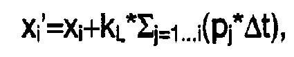
- Konstante Leckage pro zurückgelegter Wegeinheit bei Verarbeitung ohne Rückstromsperre (z.B. bei der Verarbeitung von PVC). Diese Prozessschwankung kann als Transformationsparameter einem Faktor kL zugeordnet werden, der einer linearen Umskalierung (der Messfunktion in Bezug auf die Referenzfunktion) gemäß der folgenden mathematischen Transformation entspricht:

- Leckage der Rückstromsperre proportional zum aktuell anstehenden Druck (mathematische Transformation:
- Schwankungen des Anfangsdrucks, z.B. bei unzureichender Kompressionsentlastung. Diese Prozessschwankung kann als Transformationsparameter einer Verschiebung in Richtung des Drucks zugeordnet werden:

- Schwankungen der Schmelzetemperatur und/oder des Durchflusses bzw. der Vorlauftemperatur im Falle einer Werkzeugkühlung. Derartige Prozessschwankungen können mithilfe der folgenden mathematischen Transformation erfasst werden:

- Constant leakage per travel unit covered when processing without a non-return valve (e.g. when processing PVC). This process variation can be assigned as a transformation parameter to a factor kL , which corresponds to a linear rescaling (of the measurement function with respect to the reference function) according to the following mathematical transformation:
- Leakage of the non-return valve proportional to the current pressure (mathematical transformation:
- Fluctuations in initial pressure, e.g. with insufficient compression relief. This process variation can be assigned as a transformation parameter to a shift in the direction of pressure:
- Fluctuations in the melt temperature and/or the flow or the flow temperature in the case of tool cooling. Such process variations can be captured using the following mathematical transformation:
Ein großer Vorteil der vorliegenden Erfindung besteht darin, dass die den verschiedenen Prozessschwankungen zugeordneten Transformationsparameter bzw. die entsprechenden Transformationen beliebig miteinander kombiniert werden können, sodass auch mehrere Prozessschwankungen gleichzeitig erkannt bzw. quantifiziert werden können. Beispielsweise lautet eine mathematische Transformation zur Quantifizierung der Prozessschwankung in Form von Schwankungen des Schussvolumens und der Prozessschwankung in Form von Schwankungen des Druckbedarfs zur Füllung wenigstens einer Kavität der Spritzgießmaschine während des Einspritzvorgangs wie folgt: ![]()
![]()
Die im Zuge des erfindungsgemäßen Verfahrens bereitgestellte Referenzfunktion kann beispielsweise dadurch ermittelt werden, dass in einem Referenzzyklus während zumindest eines Teils des Einspritzvorgangs wenigstens eine für den Einspritzvorgang charakteristische Größe für eine Vielzahl von Positionen der Einspritzvorrichtung gemessen und durch Zuordnung der jeweiligen Messwerte zu den jeweiligen Positionen die Referenzfunktion gebildet wird. Bei einem Mehrfachwerkzeug mit wenigstens zwei Kavitäten ist es darüber hinaus denkbar, dass für jede der Kavitäten während zumindest eines Teiles des Einspritzvorgangs wenigstens eine für den Einspritzvorgang in jede der Kavitäten charakteristische Größe für eine Vielzahl von Positionen der Einspritzvorrichtung gemessen und durch Zuordnung der jeweiligen Messwerte zu den jeweiligen Positionen eine Messfunktion gebildet wird. Anschließend könnte dann eine dieser Messfunktionen einer der Kavitäten als Referenzfunktion festgelegt werden oder aber eine über wenigstens zwei Messfunktionen zweier Kavitäten gemittelte Funktion als Referenzfunktion bereitgestellt werden.The reference function provided in the course of the method according to the invention can be determined, for example, by measuring at least one variable that is characteristic of the injection process for a large number of positions of the injection device during at least part of the injection process in a reference cycle and by assigning the respective measured values to the respective positions Reference function is formed. In the case of a multiple mold with at least two cavities, it is also conceivable that for each of the cavities, during at least part of the injection process, at least one variable that is characteristic of the injection process into each of the cavities is measured for a large number of positions of the injection device and by assigning the respective measured values to a measuring function is formed for the respective positions. Subsequently, one of these measurement functions of one of the cavities could then be defined as a reference function, or a function averaged over at least two measurement functions of two cavities could be provided as a reference function.
Vorteilhafterweise erfolgt die angesprochene Bestimmung des wenigstens einen frei wählbaren Transformationsparameters mittels eines Regressionsverfahrens. Beispielhaft sei an dieser Stelle die lineare Regression mit der Methode der kleinsten Fehlerquadrate skizziert:
Gegeben seien eine Referenzfunktion fR bestehend aus Wertepaaren (xR,i ,PR,i ), eine Messfunktion fM bestehend aus Wertepaaren (XMi,PM,i ), eine Transformation Uk , die die Wertepaare der Messfunktion fM in Wertepaare (xB,i ,p B,i ) der Bildfunktion fB abbildet. Im betrachteten Beispiel sei die Transformation Uk (mit denTransformationsparametem kp und p 0) definiert als: 
Given are a reference function f R consisting of pairs of values ( x R,i , P R,i ), a measurement function f M consisting of pairs of values ( X Mi ,P M,i ), a transformation U k , which represents the pairs of values of the measurement function f M into value pairs ( x B,i , p B , i ) of the image function f B . In the example considered, let the transformation U k (with the transformation parameters k p and p 0 ) be defined as:
Diese Transformation lässt die x-Werte unverändert, beinhaltet aber eine Umskalierung der p-Werte um den Faktor kp und zusätzlich eine konstante Verschiebung um einen Druckoffset p 0.
Der Fehler δ1 sei definiert als die Differenz zwischen den Druckwerten der Referenzfunktion und den Druckwerten der Bildfunktion: ![]()
The error δ 1 is defined as the difference between the pressure values of the reference function and the pressure values of the image function:![]()
Gesucht sei jene Parameterpaarung kp, p 0, welche die Quadratsumme der Fehler ![]()


![]()
Mit dem Fehler in Vektorschreibweise ε = pR - pB =pR -Xβ gilt also: ![]()
![]()
Die Lösung des Problems unter der Randbedingung ε2 → min! lautet in Matrixschreibweise: 
Die gesuchten Transformationsparameter kp und p 0 können also direkt durch einfache Matrixoperationen aus den pM,i und pR,i errechnet werden.The sought-after transformation parameters k p and p 0 can thus be calculated directly from the p M,i and p R,i using simple matrix operations.
Gemäß einem weiteren Ausführungsbeispiel der Erfindung kann es bevorzugt vorgesehen sein, dass zumindest ein Teil der Punktpaare aus dem die Messfunktion gebildet wurde, mit einer unterschiedlichen Gewichtung in die Bestimmung des wenigstens einen frei wählbaren Transformationsparameters einbezogen wird.According to a further exemplary embodiment of the invention, it can preferably be provided that at least some of the pairs of points from which the measurement function was formed are included with a different weighting in the determination of the at least one freely selectable transformation parameter.
Ferner wird vorgeschlagen, dass die Bestimmung des wenigstens einen frei wählbaren Transformationsparameters während des Einspritzvorgangs, in dem die Messfunktion gebildet wurde, oder im Anschluss an einen ersten Spritzgießzyklus erfolgt. In letzterem Falle kann es vorgesehen sein, dass die Bestimmung des wenigstens einen frei wählbaren Transformationsparameters entweder zwischen dem ersten und einem zweiten, nachfolgenden Spritzgießzyklus oder aber während eines zweiten, nachfolgenden Spritzgießzyklus erfolgt.It is also proposed that the at least one freely selectable transformation parameter be determined during the injection process in which the measurement function was formed, or following a first injection molding cycle. In the latter case, it can be provided that the at least one freely selectable transformation parameter is determined either between the first and a second, subsequent injection molding cycle or during a second, subsequent injection molding cycle.
Wie eingangs erwähnt, stellt die Quantifizierung von Prozessschwankungen bei einem Einspritzvorgang einer Spritzgießmaschine die Voraussetzung dafür dar, dass die unter Verwendung des wenigstens einen Transformationsparameters quantifizierte Prozessschwankung durch wenigstens eine entsprechende Korrekturmaßnahme ausgeglichen werden kann. Ein derartiger Ausgleich soll in einem bevorzugten Ausführungsbeispiel des erfindungsgemäßen Verfahrens vorgesehen sein. Erfolgt die Bestimmung des wenigstens einen Transformationsparameters während des Einspritzvorgangs, in dem die Messfunktion gebildet wurde, so kann der Ausgleich der unter Verwendung dieses wenigstens einen Transformationsparameters quantifizierten Prozessschwankung durch die wenigstens eine entsprechende Korrekturmaßnahme noch in dem Spritzgießzyklus des Einspritzvorgangs, in dem die Messfunktion gebildet wurde, erfolgen. In manchen Fällen kann es aber auch vorteilhaft sein, dass sich der Ausgleich der unter Verwendung des wenigstens einen Transformationsparameters quantifizierten Prozessschwankung durch die wenigstens eine entsprechende Korrekturmaßnahme über wenigstens einen dem Spritzgießzyklus, in dem die Prozessschwankung quantifiziert wurde, nachfolgenden Spritzgießzyklus erstreckt.As mentioned above, the quantification of process fluctuations during an injection process of an injection molding machine is the prerequisite for the process fluctuation quantified using the at least one transformation parameter to be able to be compensated for by at least one appropriate corrective measure. Such compensation should be provided in a preferred embodiment of the method according to the invention. If the at least one transformation parameter is determined during the injection process in which the measurement function was formed, the process fluctuation quantified using this at least one transformation parameter can be compensated for by the at least one corresponding corrective measure in the injection molding cycle of the injection process in which the measurement function was formed , take place. In some cases, however, it can also be advantageous for the at least one corresponding corrective measure to compensate for the process fluctuation quantified using the at least one transformation parameter over at least one injection molding cycle following the injection molding cycle in which the process fluctuation was quantified.
Beispielhaft seien folgende Korrekturmaßnahmen genannt:
- Bei einer Prozessschwankung in Form von Schwankungen des Schussvolumens können mögliche Korrekturmaßnahmen darin bestehen, dass
- ∘ der Umschaltpunkt verschoben wird,
- ∘ das restliche Einspritzprofil verschoben wird,
- ∘ das Geschwindigkeitsprofil beim Einspritzen korrigiert wird und/oder
- ∘ die Nachdruckzeit verändert wird, sodass sich die Endposition der Einspritzvorrichtung um Δx verschiebt.
- Im Falle einer Prozessschwankung in Form von Schwankungen des Druckbedarfs zur Füllung wenigstens einer Kavität der Spritzgießmaschine während des Einspritzvorgangs bestehen mögliche Korrekturmaßnahmen darin,
- ∘ den Umschaltdruck,
- ∘ die Nachdruckhöhe und/oder
- ∘ das Nachdruckprofil zu verändern.
- Handelt es sich bei der Prozessschwankung um Schwankungen der Schmeizetemperatur oder Schwankungen des Durchflusses bzw. der Vorlauftemperatur im Falle einer Werkzeugkühlung, so kann eine mögliche Korrekturmaßnahme darin bestehen, die Zylindertemperatur, die Heißkanaltemperatur und/oder (über die Durchflussmenge bzw. Vorlauftemperatur) die Werkzeugtemperatur zu verändern, so dass der Forminnentemperaturverlauf unverändert bleibt.
- In the case of a process fluctuation in the form of fluctuations in the shot volume, possible corrective measures can be that
- ∘ the switching point is shifted,
- ∘ the rest of the injection profile is shifted,
- ∘ the velocity profile during injection is corrected and/or
- ∘ the holding pressure time is changed so that the end position of the injection device is shifted by Δx.
- In the event of a process fluctuation in the form of fluctuations in the pressure required to fill at least one cavity of the injection molding machine during the injection process, possible corrective measures are:
- ∘ the switching pressure,
- ∘ the packing level and/or
- ∘ to change the packing profile.
- If the process fluctuations are fluctuations in the melt temperature or fluctuations in the flow or the flow temperature in the case of mold cooling, a possible corrective measure can be to increase the cylinder temperature, the hot runner temperature and/or (via the flow rate or flow temperature) the mold temperature change so that the internal mold temperature profile remains unchanged.
Gemäß einem weiteren Aspekt der Erfindung wird Schutz auch begehrt für eine Spritzgießmaschine mit einer über eine Vielzahl von Positionen verschiebbaren Einspritzvorrichtung, insbesondere Schnecke, einer Messvorrichtung zur Messung der Positionen der Einspritzvorrichtung, wenigstens einer Messvorrichtung zur Messung wenigstens einer für den Einspritzvorgang der Spritzgießmaschine charakteristischen Größe, wenigstens einer Kavität und einer Steuerungs- und/oder Regelungseinrichtung zur Durchführung des erfindungsgemäßen Verfahrens.According to a further aspect of the invention, protection is also sought for an injection molding machine with an injection device that can be moved over a large number of positions, in particular a screw, a measuring device for measuring the positions of the injection device, at least one measuring device for measuring at least one variable that is characteristic of the injection process of the injection molding machine, at least one cavity and a control and/or regulating device for carrying out the method according to the invention.
Weitere Einzelheiten und Vorteile der vorliegenden Erfindung werden anhand der Figurenbeschreibung unter Bezugnahme auf die in den Zeichnungen dargestellten Ausführungsbeispielen im Folgenden näher erläutert. Darin zeigen
- Fig. 1
- eine schematisch dargestellte perspektivische Gesamtansicht einer Spritzgießmaschine,
- Fig. 2
- die zur Durchführung des erfindungsgemäßen Verfahrens wesentlichen Teile einer Einspritzeinrichtung einer Spritzgießmaschine in einem schematisch dargestellten horizontalen Schnitt,
- Fig. 3
- ein schematisch dargestelltes Diagramm zur Illustration des erfindungsgemäßen Verfahrens,
- Fig. 4a und 4b
- Beispielkurven für den Verlauf des Einspritzdrucks in Abhängigkeit von der Position der Einspritzvorrichtung im Falle einer Prozessschwankung in Form von Schwankungen des Schussvolumens,
- Fig. 5a und 5b
- Beispielkurven für den Verlauf des Schmelzedrucks in Abhängigkeit von der Position der Einspritzvorrichtung im Falle einer Prozessschwankung in Form von Schwankungen des Schussvolumens,
- Fig. 6a und 6b
- Beispielkurven für den Verlauf des Forminnendrucks in Abhängigkeit von der Position der Einspritzvorrichtung im Falle einer Prozessschwankung in Form von Schwankungen des Schussvolumens,
- Fig. 7a und 7b
- Beispielkurven für den Verlauf des Einspritzdrucks bei Vorliegen einer Prozessschwankung in Form von Schwankungen des Schussvolumens und einer Prozessschwankung in Form von Schwankungen des Druckbedarfs zur Füllung wenigstens einer Kavität der Spritzgießmaschine während des Einspritzvorgangs.
- Fig. 8a und 8b
- Beispielkurven im Falle einer Schwankung der Forminnentemperatur und
- Fig. 9a und 9b
- Beispielkurven für den Verlauf des Einspritzdrucks in den unterschiedlichen Kavitäten eines Mehrfachwerkzeugs.
- 1
- a schematic perspective overall view of an injection molding machine,
- 2
- the parts of an injection device of an injection molding machine that are essential for carrying out the method according to the invention in a diagrammatic horizontal section,
- 3
- a diagram shown schematically to illustrate the method according to the invention,
- Figures 4a and 4b
- Example curves of the course of the injection pressure as a function of the position of the injector in the event of a process fluctuation in the form of fluctuations in the shot volume,
- Figures 5a and 5b
- Example curves for the course of the melt pressure as a function of the position of the injection device in the event of a process fluctuation in the form of fluctuations in the shot volume,
- Figures 6a and 6b
- Example curves for the course of the internal mold pressure as a function of the position of the injection device in the event of a process fluctuation in the form of fluctuations in the shot volume,
- Figures 7a and 7b
- Example curves for the course of the injection pressure in the presence of a process fluctuation in the form of fluctuations in the shot volume and a process fluctuation in the form of fluctuations in the pressure requirement to fill at least one cavity of the injection molding machine during the injection process.
- Figures 8a and 8b
- Example curves in the case of a variation in mold internal temperature and
- Figures 9a and 9b
- Sample curves for the course of the injection pressure in the different cavities of a multi-cavity mold.
In der
In der
Ein Spritzgießzyklus besteht im Wesentlichen aus zwei Teilen - dem Dosiervorgang und dem Einspritzvorgang. Während des Dosiervorgangs wird Kunststoffgranulat in den Trichter 7 eingefüllt und gelangt in den Bereich der sich drehenden Plastifizierschnecke 2. Durch die Drehbewegung der Schnecke 2 wird das Kunststoffgranulat in Richtung des Schneckenvorraums 8 nach links bewegt und dabei gleichzeitig durch die auftretende Scherwärme und die in manchen Fällen zusätzlich über das Heizen des Plastifizierzylinders 4 zugeführte Wärme plastifiziert. Die Kunststoffschmelze fließt weiterer Folge während des Dosiervorgangs über die geöffnete Rückstromsperre in den Schneckenvorraum 8, sammelt sich dort an und schiebt dadurch die Plastifizierschnecke 2 nach rechts.An injection molding cycle essentially consists of two parts - the dosing process and the injection process. During the dosing process, plastic granulate is filled into the
Wenn sich genügend Kunststoffschmelze in dem Schneckenvorraum 8 angesammelt hat, wird die Rückstromsperre geschlossen und es kann der Einspritzvorgang beginnen. Dazu wird die in manchen Fällen vorhandene Verschlussdüse 9 geöffnet und gleichzeitig die gesamte Schnecke 2 nach links verschoben. Dadurch wird die Kunststoffschmelze aus dem Schneckenvorraum 8 durch den sogenannten Heißkanal in die Kavität 13, die sich zwischen den beiden Formhälften 11 eines Werkzeugs 10 befindet, gepresst. Mit dem Bezugszeichen 12 ist die Werkzeugtrennebene der beiden Formhälften 11 bezeichnet.When sufficient plastic melt has accumulated in the space in front of the
Bei dem in der
Wie bereits ausgeführt, können nun während des Einspritzvorgangs der Kunststoffschmelze in die Kavität 13 unterschiedliche Prozessschwankungen auftreten, welche die Formteilqualität negativ beeinflussen. Hierzu zählen Schwankungen des Schussvolumens und Schwankungen des Druckbedarfs zur Füllung der Kavität 13. Ein erfindungsgemäßer Verfahrensschritt zur Quantifizierung dieser Prozessschwankungen besteht darin, dass während des Einspritzvorgang für den Einspritzvorgang charakteristische Größen für eine Vielzahl von Positionen x der Schnecke 2 gemessen, und durch Zuordnung der jeweiligen Messwerte zu den jeweiligen Positionen x Messfunktionen fM gebildet werden. Zu diesen charakteristischen Größen gehören der Einspritzdruck pe, der Schmelzedruck ps, der Forminnendruck pi und/oder die Forminnentemperatur Ti. Zur Messung dieser Größen sind entsprechende Druck- bzw. Temperatursensoren 14, 15, 16 und 17 vorgesehen. In dem in der
In der
Konkrete Beispiele dieses Verfahrens seien im Folgenden anhand der ![]()
![]()
in den Figurenpaaren 5a/5b, 6a/6b und 7a/7b sind weitere derartige Beispiele dargestellt, wobei in den
Im Falle des Figurenpaares 8a/8b wurde als charakteristische Größe die Forminnentemperatur Ti in Abhängigkeit von der Schneckenposition x gemessen und auf die Messfunktion die mathematische Transformation ![]()
![]()
Das Figurenpaar 9a/9b zeigt ein Beispiel für die Verläufe des Forminnendrucks pi in Abhängigkeit von der Position x der Schnecke in den einzelnen Kavitäten eines 4-fach Werkzeugs. Die pi(x)-Verläufe unterscheiden sich deutlich voneinander. Als Referenzkurve wurde die Kurve pi(x) festgelegt. Die Druckverläufe der übrigen Kavitäten wurden mit Hilfe der Transformation ![]()
![]()
Claims (15)
- A method of quantifying process fluctuations (Pi) in an injection process of an injection moulding machine (1) which has an injection device (2), in particular a screw (2), displaceable over a plurality of positions (x), characterised in that- at least one mathematical transformation (Uk) which transforms an output function (fA) into an image function (fB) in dependence on at least one freely selectable transformation parameter (uj) is provided, wherein a process fluctuation (Pi) is associated with the at least one transformation parameter (uj),- during at least a part of the injection process at least one value (pe, ps, pi, Ti) characteristic of the injection process is measured for a plurality of positions (x) of the injection device (2) and a measurement function (fM) is formed by association of the respective measurement values with the respective positions,- a reference function (fR) is provided which is of a predetermined value for each of the positions (x) of the injection device (2), at which the characteristic value (pe, ps, pi, Ti) was measured,- the measurement function (fM) is used as an output function (fA) for the at least one provided mathematical transformation (Uk), wherein the at least one freely selectable transformation parameter (uj) of said at least one mathematical transformation (Uk) is so determined that the resulting image function (fB) coincides to the best possible degree with the reference function (fR) in relation to a predetermined error size and the process fluctuation (Pi) associated with said transformation parameter (uj) is quantified in relation to the reference function (fR) using the at least one transformation parameter (uj),- one of the process fluctuations (Pi) is fluctuations in the shot volume and one of the process fluctuations is fluctuations in the pressure requirement for filling at least one cavity (13) of the injection moulding machine (1) during the injection process.
- A method according to claim 1 characterised in that an injection pressure (pe), a melt pressure (ps), an internal mould pressure (pi), an internal mould temperature (Ti), an injection speed, a drive moment and/or an injection work is measured as the value characteristic of the injection process.
- A method according to claim 1 or 2, characterised in that the process fluctuation is associated in the form of fluctuations in the shot volume with a displacement (Δx) of the measurement function (fM) in relation to the reference function (fR) in the displacement direction (x) of the injection device (2) as a transformation parameter (uj).
- A method according to at least one of claims 1 to 3, wherein the injection pressure (pe), the melt pressure (ps) and/or the internal mould pressure (pi) is measured as the value characteristic of the injection process, characterised in that the process fluctuation is associated in the form of fluctuations in the pressure requirement for filling at least one cavity (13) of the injection moulding machine (1) during an injection process with a scaling (kp) of the measurement function (fM) in relation to the reference function (fR) in the direction of the measured injection pressure (pe), melt pressure (ps) and internal mould pressure (pi) respectively as the transformation parameter (uj).
- A method according to one of claims 1 to 4, characterised in that in a reference cycle during at least a part of the injection process at least one value (pe, ps, pi, Ti) characteristic of the injection process is measured for a plurality of positions (x) of the injection device (2) and the reference function (fR) is formed by association of the respective measurement values with the respective positions.
- A method according to one of claims 1 to 5, characterised in that in the case of a multiple tool having at least two cavities (13), for each of the cavities (13) during at least a part of the injection process at least one value (pi, Ti) characteristic of the injection process into each of the cavities (13) is measured for a plurality of positions (x) of the injection device (2) and a measurement function (fM) is formed by association of the respective measurement values with the respective positions.
- A method according to claim 6, characterised in that a measurement function (fM) of a cavity (13) is established as a reference function (fR) or a function averaged over at least two measurement functions (fM) of two cavities (13) is provided as the reference function (fR).
- A method according to one of claims 1 to 7, characterised in that the operation of determining the at least one freely selectable transformation parameter (uj) is effected by means of a regression method.
- A method according to one of claims 1 to 8, characterised in that at least some of the pairs of points from which the measurement function (fM) was formed is incorporated with a differing weighting into the determination of the at least one freely selectable transformation parameter (uj).
- A method according to one of claims 1 to 9, characterised in that the operation of determining the at least one freely selectable transformation parameter (uj) is effected during the injection process in which the measurement function (fM) was formed or the operation of determining the at least one freely selectable transformation parameter (uj) is effected following a first injection moulding cycle.
- A method according to claim 10, wherein the operation of determining the at least one freely selectable transformation parameter (uj) is effected following a first injection moulding cycle, characterised in that the operation of determining the at least one freely selectable transformation parameter (uj) is effected between the first and a second subsequent injection moulding cycle or during a second subsequent injection moulding cycle.
- A method according to one of claims 1 to 11, characterised in that the process fluctuation quantified using the at least one transformation parameter (uj) is compensated by at least one suitable correction measure.
- A method according to claim 12, wherein the operation of determining the at least one transformation parameter (uj) is effected during the injection process in which the measurement function (fM) was formed, characterised in that compensation of the process fluctuation quantified using said at least one transformation parameter (uj) is effected by the at least one suitable correction measure in the injection moulding cycle of the injection process, in which the measurement function (fM) was formed.
- A method according to claim 12, characterised in that compensation of the process fluctuation quantified using said at least one transformation parameter (uj) by the at least one suitable correction measure extends over at least one injection moulding cycle following the injection moulding cycle in which the process fluctuation was quantified.
- An injection moulding machine (1) having an injection device (2), in particular a screw (2), displaceable over a plurality of positions (x), a measuring device for measuring the positions (x) of the injection device (2), at least one measuring device (17, 14, 15, 16) for measuring at least one value (pe, ps, pi, Ti) characteristic of the injection process of the injection moulding machine (1), at least one cavity (13) and a control and/or regulating device (18) which is adapted to carry out the method according to one of claims 1 to 14.
Applications Claiming Priority (1)
| Application Number | Priority Date | Filing Date | Title |
|---|---|---|---|
| ATA1518/2011A AT511391B1 (en) | 2011-10-18 | 2011-10-18 | METHOD FOR QUANTIFYING PROCESS FLUCTUATIONS IN AN INJECTION OPERATION OF AN INJECTION MOLDING MACHINE |
Publications (3)
| Publication Number | Publication Date |
|---|---|
| EP2583811A1 EP2583811A1 (en) | 2013-04-24 |
| EP2583811B1 EP2583811B1 (en) | 2015-03-11 |
| EP2583811B2 true EP2583811B2 (en) | 2023-04-12 |
Family
ID=46851789
Family Applications (1)
| Application Number | Title | Priority Date | Filing Date |
|---|---|---|---|
| EP12006404.3A Active EP2583811B2 (en) | 2011-10-18 | 2012-09-12 | Method for quantifying process fluctuations in the injection process of a injection moulding machine |
Country Status (3)
| Country | Link |
|---|---|
| EP (1) | EP2583811B2 (en) |
| CN (1) | CN103112138B (en) |
| AT (1) | AT511391B1 (en) |
Families Citing this family (13)
| Publication number | Priority date | Publication date | Assignee | Title |
|---|---|---|---|---|
| AT514847B1 (en) * | 2013-09-30 | 2015-06-15 | Engel Austria Gmbh | Method for determining a setpoint for a setting parameter |
| DE102013111257B3 (en) | 2013-10-11 | 2014-08-14 | Kraussmaffei Technologies Gmbh | Method for volumetrically correct filling of cavity of molding tool with melt of material to be processed in injection molding process, involves providing injection molding machine equipped with molding tool |
| DE102013111328A1 (en) * | 2013-10-14 | 2015-04-16 | Kraussmaffei Technologies Gmbh | Process for assessing process properties of injection molds |
| JP6625349B2 (en) * | 2015-06-01 | 2019-12-25 | 住友重機械工業株式会社 | Injection molding machine |
| US10836088B2 (en) | 2017-04-25 | 2020-11-17 | Kistler Holding, Ag | Method for reproducing injection molded parts of quality and injection molding unit for performing the method |
| DE102018107233A1 (en) * | 2018-03-27 | 2019-10-02 | Kraussmaffei Technologies Gmbh | Method for automatic process monitoring and process diagnosis of a piece-based process (batch production), in particular an injection molding process and a machine performing the process or a machine park performing the process |
| EP3546179B1 (en) * | 2018-03-28 | 2021-01-13 | Kistler Holding AG | Method for reproducing an injection molded part quality in injection molding and injection molding unit for performing said method |
| JP7114802B2 (en) * | 2018-10-05 | 2022-08-08 | キストラー ホールディング アクチエンゲゼルシャフト | Method for controlling an injection molding system |
| DE102018126313A1 (en) | 2018-10-23 | 2020-04-23 | Kraussmaffei Technologies Gmbh | Method for operating an injection molding machine, in particular with regard to improved constant mold filling, and injection molding machine for carrying out the method |
| CN110587867B (en) * | 2019-09-16 | 2022-01-21 | 费斯托气动有限公司 | Sectional compensation design method for valve seat mold |
| CN115071090B (en) * | 2022-06-13 | 2023-10-27 | 深圳市精研科洁科技股份有限公司 | Injection molding quantity dynamic compensation system and method based on injection foaming forming mold |
| AT526314A2 (en) | 2022-07-11 | 2024-01-15 | Engel Austria Gmbh | METHOD AND DEVICE FOR VISUALIZING OR ASSESSING A PROCESS CONDITION |
| DE102022127260A1 (en) | 2022-10-18 | 2024-04-18 | Arburg Gmbh + Co Kg | Process key figure determination |
Citations (4)
| Publication number | Priority date | Publication date | Assignee | Title |
|---|---|---|---|---|
| EP0372899A1 (en) † | 1988-12-08 | 1990-06-13 | Trinova Limited | Apparatus and method for the simultaneous control of two or more related variables |
| WO1991014562A1 (en) † | 1990-03-28 | 1991-10-03 | Moldflow Pty. Ltd. | Control of injection moulding machine |
| DE19801881C1 (en) † | 1998-01-20 | 1999-05-27 | Karl Hehl | Assessment of molding quality achieved by pressure injection molding machine |
| EP0784535B1 (en) † | 1994-09-28 | 1999-06-02 | Arburg GmbH & Co. | Method of influencing machine setting values and device for carrying out the method |
Family Cites Families (9)
| Publication number | Priority date | Publication date | Assignee | Title |
|---|---|---|---|---|
| DE3737959A1 (en) * | 1987-11-07 | 1989-05-18 | Philips Patentverwaltung | METHOD FOR CONTROLLING THE PRESSURE PERIOD OF AN INJECTION MOLDING MACHINE |
| JP2629334B2 (en) * | 1989-01-31 | 1997-07-09 | 三菱樹脂株式会社 | Injection molding method |
| JP2756077B2 (en) * | 1993-12-27 | 1998-05-25 | 東芝機械株式会社 | Automatic setting method of injection molding speed condition of injection molding machine |
| JPH09123241A (en) * | 1995-10-27 | 1997-05-13 | Sodick Co Ltd | Injection controlling method for screw preplasticating type injection molding machine |
| JPH09225983A (en) * | 1996-02-23 | 1997-09-02 | Ube Ind Ltd | Molding condition pattern-setting method for molding device |
| JP3255609B2 (en) * | 1998-06-05 | 2002-02-12 | 東芝機械株式会社 | Injection speed switching control method for electric injection molding machine |
| JP3440413B2 (en) * | 2000-06-12 | 2003-08-25 | 住友重機械工業株式会社 | Screw position control method for high-speed injection and high-speed depressurization |
| DE102008037098A1 (en) | 2008-08-08 | 2010-02-18 | Sumitomo (Shi) Demag Plastics Machinery Gmbh | Injection deviation controlling method for worm of injection molding machine, involves arranging worm in plasticizing and/or injection unit, and activating injection drive till worm runs in corrected injection deviation path |
| EP2174769A1 (en) * | 2008-10-07 | 2010-04-14 | Neo-plastic Dr. Doetsch Diespeck GmbH | Injection moulding method and corresponding assembly |
-
2011
- 2011-10-18 AT ATA1518/2011A patent/AT511391B1/en active
-
2012
- 2012-09-12 EP EP12006404.3A patent/EP2583811B2/en active Active
- 2012-10-18 CN CN201210396257.4A patent/CN103112138B/en active Active
Patent Citations (4)
| Publication number | Priority date | Publication date | Assignee | Title |
|---|---|---|---|---|
| EP0372899A1 (en) † | 1988-12-08 | 1990-06-13 | Trinova Limited | Apparatus and method for the simultaneous control of two or more related variables |
| WO1991014562A1 (en) † | 1990-03-28 | 1991-10-03 | Moldflow Pty. Ltd. | Control of injection moulding machine |
| EP0784535B1 (en) † | 1994-09-28 | 1999-06-02 | Arburg GmbH & Co. | Method of influencing machine setting values and device for carrying out the method |
| DE19801881C1 (en) † | 1998-01-20 | 1999-05-27 | Karl Hehl | Assessment of molding quality achieved by pressure injection molding machine |
Non-Patent Citations (4)
| Title |
|---|
| "Qualitätssicherung durch Prozessüberwachung", KISTLER: QS IM SPRITZGIESSBETRIEB, 1987, pages 129 - 142 † |
| DRILLICH, D.: "Spritzgießen/Prozessdatenverarbeitung Qualitätssicherung", STUDIENARBEIT, FAKULTÄT MASCHINENWESEN, RWTH AACHEN, October 1989 (1989-10-01), pages 88 - 89 † |
| Karlinger, P. et al, Van Quelitätsmerkmalen zu Einstelldaten, Kunststoffe 82 (1992) 3 † |
| RHEINFELD, D.; ET AL.: "Anwendung von Prozessregel- und -steuergeräten bei der Spritzgieß-Verarbeitung", KUNSTSTOFFE, vol. 65, no. 8, 1975, pages 448 - 455 † |
Also Published As
| Publication number | Publication date |
|---|---|
| EP2583811A1 (en) | 2013-04-24 |
| CN103112138B (en) | 2015-04-08 |
| AT511391A1 (en) | 2012-11-15 |
| CN103112138A (en) | 2013-05-22 |
| EP2583811B1 (en) | 2015-03-11 |
| AT511391B1 (en) | 2013-02-15 |
Similar Documents
| Publication | Publication Date | Title |
|---|---|---|
| EP2583811B2 (en) | Method for quantifying process fluctuations in the injection process of a injection moulding machine | |
| EP3055116B1 (en) | Method for controlling a mold filling process of an injection-molding machine | |
| DE60224967T2 (en) | Model-based predictive control apparatus and method for controlling the movement and / or pressure of injection molding machines | |
| EP3359365B1 (en) | Method for determining an actual volume of an injection-mouldable compound in an injection-moulding process | |
| EP2358514B1 (en) | Setting method for the semi-automatic production of a process-capable basic setting for an injection molding machine | |
| DE102015114845B4 (en) | Method and device for injection molding plastic materials | |
| EP3057760B1 (en) | Method for evaluating process characteristics of injection-molding tools | |
| DE102004031546A1 (en) | Method for filling at least one cavity | |
| AT514847B1 (en) | Method for determining a setpoint for a setting parameter | |
| DE102011102313A1 (en) | Control device for electrical operated injection molding machine, has reference value calculating unit computing value obtained from parts of screw retreat amount and screw rotation amount as plasticizing rate reference value | |
| WO2002076704A1 (en) | Method for regulating the contraction of molded parts | |
| DE19544634A1 (en) | Process for blow molding hollow bodies made of thermoplastic | |
| DE102018126313A1 (en) | Method for operating an injection molding machine, in particular with regard to improved constant mold filling, and injection molding machine for carrying out the method | |
| WO2010017940A1 (en) | Method for regulating and/or controlling functions of an injection moulding machine | |
| DE3608973C2 (en) | Method and device for controlling the switchover from the holding pressure phase to the isochoric cooling phase during injection molding of thermoplastics | |
| EP0451239B1 (en) | Process for the production of hollow bodies from thermoplastic material | |
| WO2007023013A1 (en) | Method, control for a machine and computer program product for controlling a machine for producing a molded element, especially injection molding method | |
| EP3157727B1 (en) | Method for operating an injection-moulding machine | |
| EP0407847B1 (en) | Method and apparatus for manufacturing hollow thermoplastic bodies | |
| DE102017117003A1 (en) | Storage container for a molding machine | |
| DE102014014172A1 (en) | Method for determining a sealing point | |
| DE102017000239B4 (en) | Method for determining the position of an introduction point of a driving force or a closing force in a mold clamping unit, method for producing a molded part by means of a mold clamping unit and mold clamping unit for a molding machine | |
| DE102009052080A1 (en) | Injection molding machine and method for controlling the same | |
| EP0699514A2 (en) | Computer supported process to determine the optimum working point of an injection molding machine | |
| EP0171609A2 (en) | Apparatus for controlling and/or limiting the mould separation force in injection-moulding machines |
Legal Events
| Date | Code | Title | Description |
|---|---|---|---|
| PUAI | Public reference made under article 153(3) epc to a published international application that has entered the european phase |
Free format text: ORIGINAL CODE: 0009012 |
|
| AK | Designated contracting states |
Kind code of ref document: A1 Designated state(s): AL AT BE BG CH CY CZ DE DK EE ES FI FR GB GR HR HU IE IS IT LI LT LU LV MC MK MT NL NO PL PT RO RS SE SI SK SM TR |
|
| AX | Request for extension of the european patent |
Extension state: BA ME |
|
| 17P | Request for examination filed |
Effective date: 20131024 |
|
| RBV | Designated contracting states (corrected) |
Designated state(s): AL AT BE BG CH CY CZ DE DK EE ES FI FR GB GR HR HU IE IS IT LI LT LU LV MC MK MT NL NO PL PT RO RS SE SI SK SM TR |
|
| RIC1 | Information provided on ipc code assigned before grant |
Ipc: B29C 45/76 20060101AFI20140716BHEP |
|
| GRAP | Despatch of communication of intention to grant a patent |
Free format text: ORIGINAL CODE: EPIDOSNIGR1 |
|
| INTG | Intention to grant announced |
Effective date: 20141008 |
|
| GRAS | Grant fee paid |
Free format text: ORIGINAL CODE: EPIDOSNIGR3 |
|
| GRAA | (expected) grant |
Free format text: ORIGINAL CODE: 0009210 |
|
| STAA | Information on the status of an ep patent application or granted ep patent |
Free format text: STATUS: THE PATENT HAS BEEN GRANTED |
|
| AK | Designated contracting states |
Kind code of ref document: B1 Designated state(s): AL AT BE BG CH CY CZ DE DK EE ES FI FR GB GR HR HU IE IS IT LI LT LU LV MC MK MT NL NO PL PT RO RS SE SI SK SM TR |
|
| REG | Reference to a national code |
Ref country code: GB Ref legal event code: FG4D Free format text: NOT ENGLISH |
|
| REG | Reference to a national code |
Ref country code: CH Ref legal event code: EP |
|
| REG | Reference to a national code |
Ref country code: CH Ref legal event code: NV Representative=s name: ISLER AND PEDRAZZINI AG, CH |
|
| REG | Reference to a national code |
Ref country code: IE Ref legal event code: FG4D Free format text: LANGUAGE OF EP DOCUMENT: GERMAN |
|
| REG | Reference to a national code |
Ref country code: AT Ref legal event code: REF Ref document number: 715070 Country of ref document: AT Kind code of ref document: T Effective date: 20150415 |
|
| REG | Reference to a national code |
Ref country code: DE Ref legal event code: R096 Ref document number: 502012002485 Country of ref document: DE Effective date: 20150423 |
|
| REG | Reference to a national code |
Ref country code: NL Ref legal event code: VDEP Effective date: 20150311 |
|
| REG | Reference to a national code |
Ref country code: NL Ref legal event code: VDEP Effective date: 20150311 |
|
| PG25 | Lapsed in a contracting state [announced via postgrant information from national office to epo] |
Ref country code: LT Free format text: LAPSE BECAUSE OF FAILURE TO SUBMIT A TRANSLATION OF THE DESCRIPTION OR TO PAY THE FEE WITHIN THE PRESCRIBED TIME-LIMIT Effective date: 20150311 Ref country code: FI Free format text: LAPSE BECAUSE OF FAILURE TO SUBMIT A TRANSLATION OF THE DESCRIPTION OR TO PAY THE FEE WITHIN THE PRESCRIBED TIME-LIMIT Effective date: 20150311 Ref country code: HR Free format text: LAPSE BECAUSE OF FAILURE TO SUBMIT A TRANSLATION OF THE DESCRIPTION OR TO PAY THE FEE WITHIN THE PRESCRIBED TIME-LIMIT Effective date: 20150311 Ref country code: SE Free format text: LAPSE BECAUSE OF FAILURE TO SUBMIT A TRANSLATION OF THE DESCRIPTION OR TO PAY THE FEE WITHIN THE PRESCRIBED TIME-LIMIT Effective date: 20150311 Ref country code: NO Free format text: LAPSE BECAUSE OF FAILURE TO SUBMIT A TRANSLATION OF THE DESCRIPTION OR TO PAY THE FEE WITHIN THE PRESCRIBED TIME-LIMIT Effective date: 20150611 Ref country code: ES Free format text: LAPSE BECAUSE OF FAILURE TO SUBMIT A TRANSLATION OF THE DESCRIPTION OR TO PAY THE FEE WITHIN THE PRESCRIBED TIME-LIMIT Effective date: 20150311 |
|
| REG | Reference to a national code |
Ref country code: LT Ref legal event code: MG4D |
|
| PG25 | Lapsed in a contracting state [announced via postgrant information from national office to epo] |
Ref country code: GR Free format text: LAPSE BECAUSE OF FAILURE TO SUBMIT A TRANSLATION OF THE DESCRIPTION OR TO PAY THE FEE WITHIN THE PRESCRIBED TIME-LIMIT Effective date: 20150612 Ref country code: RS Free format text: LAPSE BECAUSE OF FAILURE TO SUBMIT A TRANSLATION OF THE DESCRIPTION OR TO PAY THE FEE WITHIN THE PRESCRIBED TIME-LIMIT Effective date: 20150311 Ref country code: LV Free format text: LAPSE BECAUSE OF FAILURE TO SUBMIT A TRANSLATION OF THE DESCRIPTION OR TO PAY THE FEE WITHIN THE PRESCRIBED TIME-LIMIT Effective date: 20150311 |
|
| PG25 | Lapsed in a contracting state [announced via postgrant information from national office to epo] |
Ref country code: NL Free format text: LAPSE BECAUSE OF FAILURE TO SUBMIT A TRANSLATION OF THE DESCRIPTION OR TO PAY THE FEE WITHIN THE PRESCRIBED TIME-LIMIT Effective date: 20150311 |
|
| PG25 | Lapsed in a contracting state [announced via postgrant information from national office to epo] |
Ref country code: PT Free format text: LAPSE BECAUSE OF FAILURE TO SUBMIT A TRANSLATION OF THE DESCRIPTION OR TO PAY THE FEE WITHIN THE PRESCRIBED TIME-LIMIT Effective date: 20150713 Ref country code: SK Free format text: LAPSE BECAUSE OF FAILURE TO SUBMIT A TRANSLATION OF THE DESCRIPTION OR TO PAY THE FEE WITHIN THE PRESCRIBED TIME-LIMIT Effective date: 20150311 Ref country code: EE Free format text: LAPSE BECAUSE OF FAILURE TO SUBMIT A TRANSLATION OF THE DESCRIPTION OR TO PAY THE FEE WITHIN THE PRESCRIBED TIME-LIMIT Effective date: 20150311 Ref country code: RO Free format text: LAPSE BECAUSE OF FAILURE TO SUBMIT A TRANSLATION OF THE DESCRIPTION OR TO PAY THE FEE WITHIN THE PRESCRIBED TIME-LIMIT Effective date: 20150311 Ref country code: CZ Free format text: LAPSE BECAUSE OF FAILURE TO SUBMIT A TRANSLATION OF THE DESCRIPTION OR TO PAY THE FEE WITHIN THE PRESCRIBED TIME-LIMIT Effective date: 20150311 |
|
| PG25 | Lapsed in a contracting state [announced via postgrant information from national office to epo] |
Ref country code: PL Free format text: LAPSE BECAUSE OF FAILURE TO SUBMIT A TRANSLATION OF THE DESCRIPTION OR TO PAY THE FEE WITHIN THE PRESCRIBED TIME-LIMIT Effective date: 20150311 Ref country code: IS Free format text: LAPSE BECAUSE OF FAILURE TO SUBMIT A TRANSLATION OF THE DESCRIPTION OR TO PAY THE FEE WITHIN THE PRESCRIBED TIME-LIMIT Effective date: 20150711 |
|
| REG | Reference to a national code |
Ref country code: DE Ref legal event code: R026 Ref document number: 502012002485 Country of ref document: DE |
|
| PLBI | Opposition filed |
Free format text: ORIGINAL CODE: 0009260 |
|
| PG25 | Lapsed in a contracting state [announced via postgrant information from national office to epo] |
Ref country code: IT Free format text: LAPSE BECAUSE OF FAILURE TO SUBMIT A TRANSLATION OF THE DESCRIPTION OR TO PAY THE FEE WITHIN THE PRESCRIBED TIME-LIMIT Effective date: 20150311 |
|
| PLAX | Notice of opposition and request to file observation + time limit sent |
Free format text: ORIGINAL CODE: EPIDOSNOBS2 |
|
| 26 | Opposition filed |
Opponent name: ARBURG GMBH + CO. KG Effective date: 20151211 |
|
| PG25 | Lapsed in a contracting state [announced via postgrant information from national office to epo] |
Ref country code: DK Free format text: LAPSE BECAUSE OF FAILURE TO SUBMIT A TRANSLATION OF THE DESCRIPTION OR TO PAY THE FEE WITHIN THE PRESCRIBED TIME-LIMIT Effective date: 20150311 |
|
| PG25 | Lapsed in a contracting state [announced via postgrant information from national office to epo] |
Ref country code: SI Free format text: LAPSE BECAUSE OF FAILURE TO SUBMIT A TRANSLATION OF THE DESCRIPTION OR TO PAY THE FEE WITHIN THE PRESCRIBED TIME-LIMIT Effective date: 20150311 |
|
| PG25 | Lapsed in a contracting state [announced via postgrant information from national office to epo] |
Ref country code: MC Free format text: LAPSE BECAUSE OF FAILURE TO SUBMIT A TRANSLATION OF THE DESCRIPTION OR TO PAY THE FEE WITHIN THE PRESCRIBED TIME-LIMIT Effective date: 20150311 Ref country code: LU Free format text: LAPSE BECAUSE OF FAILURE TO SUBMIT A TRANSLATION OF THE DESCRIPTION OR TO PAY THE FEE WITHIN THE PRESCRIBED TIME-LIMIT Effective date: 20150912 |
|
| PLAF | Information modified related to communication of a notice of opposition and request to file observations + time limit |
Free format text: ORIGINAL CODE: EPIDOSCOBS2 |
|
| REG | Reference to a national code |
Ref country code: IE Ref legal event code: MM4A |
|
| REG | Reference to a national code |
Ref country code: FR Ref legal event code: ST Effective date: 20160531 |
|
| PLBB | Reply of patent proprietor to notice(s) of opposition received |
Free format text: ORIGINAL CODE: EPIDOSNOBS3 |
|
| PG25 | Lapsed in a contracting state [announced via postgrant information from national office to epo] |
Ref country code: IE Free format text: LAPSE BECAUSE OF NON-PAYMENT OF DUE FEES Effective date: 20150912 |
|
| PG25 | Lapsed in a contracting state [announced via postgrant information from national office to epo] |
Ref country code: FR Free format text: LAPSE BECAUSE OF NON-PAYMENT OF DUE FEES Effective date: 20150930 |
|
| PG25 | Lapsed in a contracting state [announced via postgrant information from national office to epo] |
Ref country code: MT Free format text: LAPSE BECAUSE OF FAILURE TO SUBMIT A TRANSLATION OF THE DESCRIPTION OR TO PAY THE FEE WITHIN THE PRESCRIBED TIME-LIMIT Effective date: 20150311 |
|
| GBPC | Gb: european patent ceased through non-payment of renewal fee |
Effective date: 20160912 |
|
| PG25 | Lapsed in a contracting state [announced via postgrant information from national office to epo] |
Ref country code: BG Free format text: LAPSE BECAUSE OF FAILURE TO SUBMIT A TRANSLATION OF THE DESCRIPTION OR TO PAY THE FEE WITHIN THE PRESCRIBED TIME-LIMIT Effective date: 20150311 Ref country code: SM Free format text: LAPSE BECAUSE OF FAILURE TO SUBMIT A TRANSLATION OF THE DESCRIPTION OR TO PAY THE FEE WITHIN THE PRESCRIBED TIME-LIMIT Effective date: 20150311 Ref country code: HU Free format text: LAPSE BECAUSE OF FAILURE TO SUBMIT A TRANSLATION OF THE DESCRIPTION OR TO PAY THE FEE WITHIN THE PRESCRIBED TIME-LIMIT; INVALID AB INITIO Effective date: 20120912 |
|
| PG25 | Lapsed in a contracting state [announced via postgrant information from national office to epo] |
Ref country code: CY Free format text: LAPSE BECAUSE OF FAILURE TO SUBMIT A TRANSLATION OF THE DESCRIPTION OR TO PAY THE FEE WITHIN THE PRESCRIBED TIME-LIMIT Effective date: 20150311 |
|
| PG25 | Lapsed in a contracting state [announced via postgrant information from national office to epo] |
Ref country code: BE Free format text: LAPSE BECAUSE OF NON-PAYMENT OF DUE FEES Effective date: 20150930 Ref country code: GB Free format text: LAPSE BECAUSE OF NON-PAYMENT OF DUE FEES Effective date: 20160912 |
|
| PG25 | Lapsed in a contracting state [announced via postgrant information from national office to epo] |
Ref country code: TR Free format text: LAPSE BECAUSE OF FAILURE TO SUBMIT A TRANSLATION OF THE DESCRIPTION OR TO PAY THE FEE WITHIN THE PRESCRIBED TIME-LIMIT Effective date: 20150311 |
|
| APBM | Appeal reference recorded |
Free format text: ORIGINAL CODE: EPIDOSNREFNO |
|
| APBP | Date of receipt of notice of appeal recorded |
Free format text: ORIGINAL CODE: EPIDOSNNOA2O |
|
| APAH | Appeal reference modified |
Free format text: ORIGINAL CODE: EPIDOSCREFNO |
|
| PG25 | Lapsed in a contracting state [announced via postgrant information from national office to epo] |
Ref country code: MK Free format text: LAPSE BECAUSE OF FAILURE TO SUBMIT A TRANSLATION OF THE DESCRIPTION OR TO PAY THE FEE WITHIN THE PRESCRIBED TIME-LIMIT Effective date: 20150311 |
|
| APBQ | Date of receipt of statement of grounds of appeal recorded |
Free format text: ORIGINAL CODE: EPIDOSNNOA3O |
|
| PG25 | Lapsed in a contracting state [announced via postgrant information from national office to epo] |
Ref country code: AL Free format text: LAPSE BECAUSE OF FAILURE TO SUBMIT A TRANSLATION OF THE DESCRIPTION OR TO PAY THE FEE WITHIN THE PRESCRIBED TIME-LIMIT Effective date: 20150311 |
|
| APBU | Appeal procedure closed |
Free format text: ORIGINAL CODE: EPIDOSNNOA9O |
|
| PGFP | Annual fee paid to national office [announced via postgrant information from national office to epo] |
Ref country code: CH Payment date: 20220928 Year of fee payment: 11 |
|
| PUAH | Patent maintained in amended form |
Free format text: ORIGINAL CODE: 0009272 |
|
| STAA | Information on the status of an ep patent application or granted ep patent |
Free format text: STATUS: PATENT MAINTAINED AS AMENDED |
|
| 27A | Patent maintained in amended form |
Effective date: 20230412 |
|
| AK | Designated contracting states |
Kind code of ref document: B2 Designated state(s): AL AT BE BG CH CY CZ DE DK EE ES FI FR GB GR HR HU IE IS IT LI LT LU LV MC MK MT NL NO PL PT RO RS SE SI SK SM TR |
|
| REG | Reference to a national code |
Ref country code: DE Ref legal event code: R102 Ref document number: 502012002485 Country of ref document: DE |
|
| PGFP | Annual fee paid to national office [announced via postgrant information from national office to epo] |
Ref country code: AT Payment date: 20230928 Year of fee payment: 12 |
|
| PGFP | Annual fee paid to national office [announced via postgrant information from national office to epo] |
Ref country code: DE Payment date: 20230928 Year of fee payment: 12 |
|
| REG | Reference to a national code |
Ref country code: CH Ref legal event code: PL |