EP2583493B1 - Measurements logging and transmission at a user equipment of a mobile communications system - Google Patents
Measurements logging and transmission at a user equipment of a mobile communications system Download PDFInfo
- Publication number
- EP2583493B1 EP2583493B1 EP10727384.9A EP10727384A EP2583493B1 EP 2583493 B1 EP2583493 B1 EP 2583493B1 EP 10727384 A EP10727384 A EP 10727384A EP 2583493 B1 EP2583493 B1 EP 2583493B1
- Authority
- EP
- European Patent Office
- Prior art keywords
- area
- network
- measurements
- scheduled
- areas
- Prior art date
- Legal status (The legal status is an assumption and is not a legal conclusion. Google has not performed a legal analysis and makes no representation as to the accuracy of the status listed.)
- Active
Links
Images

Classifications
-
- H—ELECTRICITY
- H04—ELECTRIC COMMUNICATION TECHNIQUE
- H04W—WIRELESS COMMUNICATION NETWORKS
- H04W24/00—Supervisory, monitoring or testing arrangements
- H04W24/10—Scheduling measurement reports ; Arrangements for measurement reports
-
- H—ELECTRICITY
- H04—ELECTRIC COMMUNICATION TECHNIQUE
- H04W—WIRELESS COMMUNICATION NETWORKS
- H04W48/00—Access restriction; Network selection; Access point selection
- H04W48/18—Selecting a network or a communication service
Definitions
- the present invention relates to measurements logging and transmission at a user equipment (UE) of a mobile communications system.
- UE user equipment
- the present invention is applicable for 3G (third generation) and LTE (long term evolution) UEs.
- An MDT minimization of drive tests function aims at defining an automatic collection of UE measurements, to enable easier monitoring of network performance and consequently to replace expensive drive tests performed by operators manually.
- the MDT function considers re-usage of measurements defined for typical mobility control and corresponding real-time reporting mode, and has brought logging measurements and non-real time reporting mechanisms into the standard.
- a UE is configured by a mobile communications network by dedicated signalling before the UE enters an idle state, and the UE follows the configuration parameters until the next connection to the network. After entering a connected mode the UE proceeds normally with its call. Meanwhile, the network may decide to retrieve an MDT report including logged measurements from the UE.
- the UE respects the configuration for its logging session in idle, unless an ending condition (i.e. duration timer) becomes valid.
- an ending condition i.e. duration timer
- the validity of configuration may depend on a service area. For example, if no area scope for MDT measurements is configured, the MDT configuration is valid in the entire RPLMN (registered public land mobile network) of a UE.
- the RPLMN can be either an HPLMN (home PLMN) or a VPLMN (visited PLMN)
- some MDT support for roaming and inter-PLMN scenarios is required.
- radio measurements logged by the UE are recognized as an always valuable input for network optimization, and are treated as not outdated data. It is required that the UE keeps the MDT reports for network retrieval. Thus, although the configuration becomes invalid and may be erased when the UE changes the PLMN, the logged data is held in the UE. In other words, if logged data has survived in the UE to the point of network requests, it should be transferred.
- the recorded data may be retrieved by any node supporting MDT, even if it does not belong to the PLMN where configuration took place.
- the UE performs real-time reporting, and usually the above-mention problem will not occur.
- an RLF radio link failure
- the UE may reconnect to the network in another PLMN after the RLF.
- the MDT report about the RLF can only be reported after the UE reconnects to the network.
- the UE may be used for spying visited network topology.
- the measurement can be configured in one cell in connected by dedicated control, then take place during IDLE state whenever the UE is in IDLE, i.e. during multiple IDLE periods interrupted by IDLE->CONN->IDLE state transitions, and finally be reported in some other cell.
- the UE should not by default report to the new cell that it has a logged MDT. Instead the UE should retain the log in case it returns to the PLMN where the Logged MDT configuration was initiated.
- the present invention aims at preventing network information collected at a UE from being leaked.
- UE measurement logs defined for a scheduled area belonging to a network of a mobile communications network can be prevented from being routed to any other network of the mobile communications network.
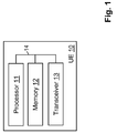
- FIG. 1 illustrates a simplified block diagram of a structure of a user equipment (UE) 10 that is suitable for use in practicing the exemplary embodiments of this invention.
- UE user equipment
- the UE 10 includes a processor 11, a memory 12 that may store a program, and a suitable radio frequency (RF) transceiver 13 coupled to one or more antennas (not shown) for bidirectional wireless communications over one or more wireless links (not shown) with a mobile communications network.
- the processor 11, the memory 12 and the transceiver 13 are coupled by a bus 14.
- connection means any connection or coupling, either direct or indirect, between two or more elements, and may encompass the presence of one or more intermediate elements between two elements that are “connected” or “coupled” together.
- the coupling or connection between the elements can be physical, logical, or a combination thereof.
- two elements may be considered to be “connected” or “coupled” together by the use of one or more wires, cables and printed electrical connections, as well as by the use of electromagnetic energy, such as electromagnetic energy having wavelengths in the radio frequency region, the microwave region and the optical (both visible and invisible) region, as non-limiting examples.
- the memory 12 may store a program which may include program instructions that, when executed by the processor 11, enable the UE 10 to operate in accordance with the exemplary embodiments of this invention, as detailed below.
- Inherent in the processor 11 is a clock to enable synchronism among the various apparatus for transmissions and receptions within the appropriate time intervals and slots required, as the scheduling grants and the granted resources/subframes are time dependent.
- the transceiver 13 includes both transmitter and receiver, and inherent in each is a modulator/demodulator commonly known as a modem.
- the exemplary embodiments of this invention may be implemented by computer software stored in the memory 12 and executable by the processor 11 of the UE 10, or by hardware, or by a combination of software and/or firmware and hardware, which may include integrated circuit modules.
- the design of integrated circuits is by and large a highly automated process. Complex and powerful software tools are available for converting a logic level design into a semiconductor circuit design ready to be etched and formed on a semiconductor substrate. Programs, such as those provided by Synopsys, Inc. of Mountain View, California and Cadence Design, of San Jose, California automatically route conductors and locate components on a semiconductor chip using well established rules of design as well as libraries of pre-stored design modules.
- the resultant design in a standardized electronic format (e.g., Opus, GDSII, or the like) may be transmitted to a semiconductor fabrication facility or "fab" for fabrication.
- a standardized electronic format e.g., Opus, GDSII, or the like
- the various embodiments of the UE 10 can include, but are not limited to, mobile stations, cellular telephones, personal digital assistants (PDAs) having wireless communication capabilities, portable computers having wireless communication capabilities, image capture devices such as digital cameras having wireless communication capabilities, gaming devices having wireless communication capabilities, music storage and playback appliances having wireless communication capabilities, Internet appliances permitting wireless Internet access and browsing, as well as portable units or terminals that incorporate combinations of such functions.
- PDAs personal digital assistants
- portable computers having wireless communication capabilities
- image capture devices such as digital cameras having wireless communication capabilities
- gaming devices having wireless communication capabilities
- music storage and playback appliances having wireless communication capabilities
- Internet appliances permitting wireless Internet access and browsing, as well as portable units or terminals that incorporate combinations of such functions.
- the memory 12 may be of any type suitable to the local technical environment and may be implemented using any suitable data storage technology, such as semiconductor-based memory devices, magnetic memory devices and systems, optical memory devices and systems, fixed memory and removable memory.
- the processor 11 may be of any type suitable to the local technical environment, and may include one or more of general purpose computers, special purpose computers, microprocessors, digital signal processors (DSPs) and processors based on a multi-core processor architecture, as non-limiting examples.
- the processor 11 performs measurements logging which has been defined for a scheduled area belonging to a network of a mobile communications network.
- the measurements logging defined for the scheduled area may comprise measurements logging defined for the network of the scheduled area, e.g. in cases in which no measurement areas are defined. In these cases the scheduled area corresponds to the network.
- the mobile communications network may comprise a plurality of networks, and the networks each may comprise a plurality of areas.
- the mobile communications network comprises a plurality of areas which may belong to different networks.
- the measurements comprise information about performance of the scheduled area, e.g. MDT data.
- the processor 11 may cease the defined measurements logging for the scheduled area.
- the processor 11 prevents transmission of the logged measurements in case the area to which the transceiver 13 connects the UE 10 belongs to a network of the mobile communications network which is different from the network of the scheduled area.
- the processor 11 may delete the logged measurements for the scheduled area, or hold the logged measurements for a predetermined period of time and/or until the transceiver 13 re-connects the UE 10 to the network of the scheduled area, i.e.
- the condition may comprise at least one of a status of the memory 12 of the UE 10 in which the logged measurements may be stored, a status of a battery (not shown) of the UE 10 and a network condition.
- the processor 11 detects that the area to which the transceiver 13 connects the UE 10 is the scheduled area or an area belonging to the network of the scheduled area, the processor 11 allows transmission of the logged measurements for the scheduled area.
- the areas and networks may each comprise an identity
- the processor 11 may record the logged measurements for the scheduled area with the identity of the scheduled area and the identity of the network of the scheduled area.
- the processor 11 prevents transmission of the logged measurements. In this case, the processor 11 may delete the logged measurements or hold the logged measurements as described above.
- the areas of the mobile communications network may comprise at least one of the following: cells, lists of cells, tracking areas, routing areas and location areas.
- the measurements may be collected in idle and/or connected mode of the UE 10.
- Fig. 2 shows a flow chart illustrating a method of logging measurements for a scheduled area of a mobile communications network according to an embodiment of the invention.
- step S21 the UE 10 performs measurements logging configured for the scheduled area.
- the scheduled area belongs to a network of the mobile communications network. In case no particular measurements logging is defined for the scheduled area, measurements logging determined for the network of the scheduled area may be used.
- the UE 10 may be in idle mode in step S21.
- step S22 the UE 10 connects to an area of the mobile communications network. Connection may be performed to process a call, for example.
- step S23 it is checked by the UE 10 whether the connected area is identical to the scheduled area or whether the area has changed. In case the area has not changed (No in step S23), the UE 10 allows transmission of logged measurements for the area and may continue to log measurements for the area in connected mode in step S24.
- step S25 disconnection may take place. The process may return to step S21 of logging measurements for the area.
- step S26 it is checked whether also the network has changed, i.e. whether the network of the connected new area is different from the network of the previous (old) area.
- the UE 10 ceases measurements logging for the previous (old) area and inhibits transmission of logged measurements for the old area in step S27.
- the UE 10 logs measurements for the new area, and allows transmission of logged measurements for the new area in the connected mode.
- the UE 10 holds logged measurements for the new network which were collected in the past when the UE 10 was configured to log measurements for an area belonging to the new network, such logged measurements are allowed to be transmitted in the connected mode.
- the UE 10 may perform a decision as to whether it can hold logged measurements for the old network. For example, such decision may be based on a status of the memory 12 of the UE 10 in which the logged measurements may be stored, a status of a battery of the UE 10 and a network condition.
- the UE 10 holds these logged measurements e.g. in the memory 12.
- the UE 10 deletes the logged measurements for the old network.
- disconnection may take place. The process may return to step S21 of logging measurements for the new area.
- the UE 10 may cease measurements logging for the old area.
- the UE 10 allows transmission of logged measurements for the old area since the new area belongs to the same network as the old area in step S32.
- measurements logging is configured for the connected new area
- the UE 10 logs measurements for the new area, and allows transmission of logged measurements for the new area in the connected mode in step S32.
- disconnection may take place. The process may return to step S21 of logging measurements for the new area.
- step S23 may be replaced by step S26 in Fig. 2 .
- the flow chart branches to step S24 in which transmission of logged measurements for the network are allowed and measurements may be logged for the network in connected mode. If the network has changed, the flow chart braches to step S27 in which measurements logging for the old network is ceased, transmission of logged measurements for the old network is inhibited, measurements may be logged for the connected new network, and transmission of logged measurements for the new network is allowed.
- the UE 10 does not report logged MDT measurements or a log file (collected in idle or connected mode) to a network when a broadcasted public land mobile network identification (PLMN-ID) is different from the one in use when the specific measurements have been configured.
- PLMN-ID public land mobile network identification
- the relevant MDT configuration is cleared and the MDT measurements logged for the previous PLMN is prevented from being transmitted, from the moment the UE 10 has been configured for the other PLMN.
- a selected PLMN entry may be identified in a plmn identity list in SystemInformationBlockType1 read from broadcast information when multiple PLMN identities are broadcast and may be confirmed by the UE 10 during connection establishment.
- Logged MDT radio measurements may also be recorded with the identity of the PLMN for which they have been taken. Based on such records the UE 10, e.g. the processor 11, may compare to the identity of the selected PLMN after connection is established with the identity of the PLMN for which radio measurements have been captured.
- an area may comprise at least one of: cells, lists of cells, tracking areas, routing areas and location areas.
- Each area has its own identification and part of the identification may be the PLMN-ID.
- any predefined MDT configuration is ceased and the collected data is removed.
- the UE 10 depending on capabilities of the UE 10 (e.g. memory size, battery capacity) and network situation, the UE 10 keeps the logged measurements for some (limited) period of time until the next connection to the PLMN for which the logged measurements have been collected, even though there were some PLMN changes in between, and disallows transmission of the logged measurements only when an MDT report request is received from a PLMN with a different identity than that of the PLMN which configured the logging. In case the UE 10 returns to the PLMN which configured the logging, it allows transmission of the logged measurements.
- capabilities of the UE 10 e.g. memory size, battery capacity
- the merit of the solution is that UE measurement logs defined for the scheduled area are not routed to any other network.
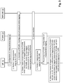
- Fig. 3 shows a signalling diagram illustration operation of the UE 10 which connects to an RPLMN 30 when collecting radio measurements for a PLMN 20, according to an embodiment of the invention.
- Step 1 the UE 10 is configured by the PLMN 20 to perform measurements logging for the PLMN 20, which the UE 10 carries out in step 2.
- Step 2 may be performed in idle mode of the UE 10 or in connected mode in which the UE 10 is connected with the PLMN 20.
- step 3 the UE 10 connects to the RPLMN 30.
- the UE 10 may be configured by the RPLMN 30 to perform measurements logging for the RPLMN 30.
- the UE 10 Upon connecting with the RPLMN 30, in step 4 the UE 10 ceases measurements logging for the PLMN 20 and inhibits transmission of logged measurements for the PLMN 20. The UE 10 may delete or hold logged measurements for the PLMN 20 as described above. In case the UE 10 is configured to perform measurements logging for the RPLMN 30 in step 3, it may perform measurements logging for the RPLMN 30 in the connected mode and, after an optional disconnection in step 5, in idle mode in step 6.
- step 7 the UE 10 re-connects to the PLMN 20.
- the UE 10 may be configured by the PLMN 20 to perform measurements logging for the PLMN 20.
- the UE 10 Upon connecting with the PLMN 20, in step 8 the UE 10 allows transmission of logged measurements for the PLMN 20 which have been collected in step 2 if still held in the UE 10.
- the UE 10 ceases measurements logging for the RPLMN 30, inhibits transmission of logged measurements for the RPLMN 30, and deletes or holds logged measurements for the RPLMN 30 as described above.
- the UE 10 is configured to perform measurements logging for the PLMN 30 in step 7
- the UE 10 may perform measurements logging for the PLMN 20 in connected mode and, after an optional disconnection, in idle mode.
- the UE 10 performs control such that logged measurements are not transmitted to another network of a mobile communications network different from the network of the area which configured the measurements logging. Also in a case when the UE 10 performs real-time reporting of logged measurements in connected mode and an RLF occurs, logged measurements can be effectively prevented from being routed to a network different from the network of the area with which the UE 10 was connected when the RLF occurred.
- an apparatus such as the UE 10 shown in Fig. 1 , comprises logging means for performing measurements logging which has been defined for a scheduled area belonging to a network of a mobile communications network, the measurements comprising information about performance of the scheduled area, connecting means for connecting the apparatus to an area of areas of the mobile communications network, detecting means for detecting to which area of the areas of the mobile communications network the connecting means connect the apparatus, and preventing means for preventing transmission of the logged measurements in case the area to which the connecting means connect the apparatus belongs to a network of the mobile communications network which is different from the network of the scheduled area.
- the logging means, detecting means and preventing means may comprise the processor 11, and the connecting means may comprise the transceiver 13.
- the apparatus may further comprise deleting means for deleting the logged measurements for the scheduled area in case the area to which the connecting means connect the apparatus belongs to a network of the mobile communications network which is different from the network of the scheduled area.
- the deleting means may comprise the processor 11.
- the apparatus may further comprise holding means for, in case the area to which the connecting means connect the apparatus belongs to a network of the mobile communications network which is different from the network of the scheduled area, holding the logged measurements for a predetermined period of time and/or until reconnecting means of the apparatus reconnect the apparatus to the network of the scheduled area, based on a condition, wherein the apparatus may comprise allowing means for allowing transmission of the logged measurements for the scheduled area in case the reconnecting means reconnect the apparatus to the network of the scheduled area.
- the holding means and allowing means may comprise the processor 11, and the reconnecting means may comprise the transceiver 13.
- the networks may each comprise an identity
- the apparatus may comprise recording means for recording the logged measurements for the scheduled area with the identity of the network of the scheduled area, and the preventing means may prevent transmission of the logged measurements and the deleting means may delete the logged measurements or the holding means may hold the logged measurements in case the identity of the network of the area to which the connecting means connect the apparatus is different from the identity of the network recorded for the logged measurements.
- the recording means may comprise the processor 11.
- the areas of the mobile communications network may comprise at least one of the following: cells, lists of cells, tracking areas, routing areas and location areas, the network of the scheduled area and the network of the area to which the connecting means connect the apparatus may be public land mobile networks, the measurements may comprise minimization drive test measurements, and the measurements may be collected in idle and/or connected mode of the apparatus.
- the measurements logging defined for the scheduled area may comprise measurements logging defined for the network of the scheduled area.
- the areas may each comprise an identity, and the recording means may record the logged measurements for the scheduled area with the identity of the scheduled area.
- a user equipment performs measurements logging which has been defined for a scheduled area belonging to a network of a mobile communications network, the measurements comprising information about performance of the scheduled area.
- the user equipment connects to an area of areas of the mobile communications network which belongs to a network different from the network of the scheduled area, the user equipment prevents transmission of the logged measurements.
Description
- The present invention relates to measurements logging and transmission at a user equipment (UE) of a mobile communications system. For example, the present invention is applicable for 3G (third generation) and LTE (long term evolution) UEs.
- An MDT (minimization of drive tests) function aims at defining an automatic collection of UE measurements, to enable easier monitoring of network performance and consequently to replace expensive drive tests performed by operators manually.
- The MDT function considers re-usage of measurements defined for typical mobility control and corresponding real-time reporting mode, and has brought logging measurements and non-real time reporting mechanisms into the standard. A UE is configured by a mobile communications network by dedicated signalling before the UE enters an idle state, and the UE follows the configuration parameters until the next connection to the network. After entering a connected mode the UE proceeds normally with its call. Meanwhile, the network may decide to retrieve an MDT report including logged measurements from the UE.
- The UE respects the configuration for its logging session in idle, unless an ending condition (i.e. duration timer) becomes valid. In addition, the validity of configuration may depend on a service area. For example, if no area scope for MDT measurements is configured, the MDT configuration is valid in the entire RPLMN (registered public land mobile network) of a UE.
- Since the RPLMN can be either an HPLMN (home PLMN) or a VPLMN (visited PLMN), some MDT support for roaming and inter-PLMN scenarios is required. However, in a network sharing scenario where MDT data collection is allowed, it is important to prevent sharing of not desired information relevant for a particular PLMN.
- Regardless of configuration validity, radio measurements logged by the UE, such as time-stamped network measurements, are recognized as an always valuable input for network optimization, and are treated as not outdated data. It is required that the UE keeps the MDT reports for network retrieval. Thus, although the configuration becomes invalid and may be erased when the UE changes the PLMN, the logged data is held in the UE. In other words, if logged data has survived in the UE to the point of network requests, it should be transferred.
- Assuming that the UE is moving while logging radio measurements, it is a likely scenario that the UE will end up in a different PLMN than where it has been configured. Thus, the recorded data may be retrieved by any node supporting MDT, even if it does not belong to the PLMN where configuration took place.
- Since MDT reports carry radio measurements, it is not desired to allow the data to reach other operators' networks.
- Moreover, during the connected mode the UE performs real-time reporting, and usually the above-mention problem will not occur. However, an RLF (radio link failure) may occur during the MDT collection. Then the UE may reconnect to the network in another PLMN after the RLF. The MDT report about the RLF can only be reported after the UE reconnects to the network.
- Thus, collecting radio measurements in the UE runs the risk of forwarding data relevant for a monitored area belonging to a network to the subsequent area belonging to a different network. Thus, the UE may be used for spying visited network topology.
- In the 3GPP draft by Alcatel-Lucent: "Idle Mode Logged MDT reporting mechanism", R2-102056 MDT, 4 April 2010, it is disclosed that for logged MDT in IDLE, the measurement can be configured in one cell in connected by dedicated control, then take place during IDLE state whenever the UE is in IDLE, i.e. during multiple IDLE periods interrupted by IDLE->CONN->IDLE state transitions, and finally be reported in some other cell. The UE should not by default report to the new cell that it has a logged MDT. Instead the UE should retain the log in case it returns to the PLMN where the Logged MDT configuration was initiated.
- Further prior art can be found in the 3GPP drafts by NTT Docomo et al.: "MDT support for roaming and network sharing scenarios", R2-102997, 4 May 2010, R3-101565, 1 May 2010, and the 3GPP draft by Huawei: "Principles for logged MDT in IDLE", R2-102912, 3 May 2010.
- The present invention aims at preventing network information collected at a UE from being leaked.
- This is achieved by an apparatus and method as defined in the appended claims. The invention may also be implemented as a computer program product.
- According to an embodiment of the invention, UE measurement logs defined for a scheduled area belonging to a network of a mobile communications network can be prevented from being routed to any other network of the mobile communications network.
- In the following embodiments of the present invention will be described with reference to the accompanying drawings, in which:
-
Fig. 1 shows a schematic block diagram illustrating a structure of a user equipment according to an embodiment of the invention; -
Fig. 2 shows a flow chart illustrating a method of logging measurements by a user equipment according to an embodiment of the invention; and -
Fig. 3 shows a signaling diagram illustrating operation of a user equipment which logs measurements and connects to different networks, according to an embodiment of the invention. - As a preliminary matter before exploring details of various implementations, reference is made to
Fig. 1 which illustrates a simplified block diagram of a structure of a user equipment (UE) 10 that is suitable for use in practicing the exemplary embodiments of this invention. - The UE 10 includes a
processor 11, amemory 12 that may store a program, and a suitable radio frequency (RF)transceiver 13 coupled to one or more antennas (not shown) for bidirectional wireless communications over one or more wireless links (not shown) with a mobile communications network. Theprocessor 11, thememory 12 and thetransceiver 13 are coupled by abus 14. - The terms "connected," "coupled," or any variant thereof, mean any connection or coupling, either direct or indirect, between two or more elements, and may encompass the presence of one or more intermediate elements between two elements that are "connected" or "coupled" together. The coupling or connection between the elements can be physical, logical, or a combination thereof. As employed herein two elements may be considered to be "connected" or "coupled" together by the use of one or more wires, cables and printed electrical connections, as well as by the use of electromagnetic energy, such as electromagnetic energy having wavelengths in the radio frequency region, the microwave region and the optical (both visible and invisible) region, as non-limiting examples.
- The
memory 12 may store a program which may include program instructions that, when executed by theprocessor 11, enable the UE 10 to operate in accordance with the exemplary embodiments of this invention, as detailed below. Inherent in theprocessor 11 is a clock to enable synchronism among the various apparatus for transmissions and receptions within the appropriate time intervals and slots required, as the scheduling grants and the granted resources/subframes are time dependent. Thetransceiver 13 includes both transmitter and receiver, and inherent in each is a modulator/demodulator commonly known as a modem. - In general, the exemplary embodiments of this invention may be implemented by computer software stored in the
memory 12 and executable by theprocessor 11 of the UE 10, or by hardware, or by a combination of software and/or firmware and hardware, which may include integrated circuit modules. The design of integrated circuits is by and large a highly automated process. Complex and powerful software tools are available for converting a logic level design into a semiconductor circuit design ready to be etched and formed on a semiconductor substrate. Programs, such as those provided by Synopsys, Inc. of Mountain View, California and Cadence Design, of San Jose, California automatically route conductors and locate components on a semiconductor chip using well established rules of design as well as libraries of pre-stored design modules. Once the design for a semiconductor circuit has been completed, the resultant design, in a standardized electronic format (e.g., Opus, GDSII, or the like) may be transmitted to a semiconductor fabrication facility or "fab" for fabrication. - In general, the various embodiments of the UE 10 can include, but are not limited to, mobile stations, cellular telephones, personal digital assistants (PDAs) having wireless communication capabilities, portable computers having wireless communication capabilities, image capture devices such as digital cameras having wireless communication capabilities, gaming devices having wireless communication capabilities, music storage and playback appliances having wireless communication capabilities, Internet appliances permitting wireless Internet access and browsing, as well as portable units or terminals that incorporate combinations of such functions.
- The
memory 12 may be of any type suitable to the local technical environment and may be implemented using any suitable data storage technology, such as semiconductor-based memory devices, magnetic memory devices and systems, optical memory devices and systems, fixed memory and removable memory. Theprocessor 11 may be of any type suitable to the local technical environment, and may include one or more of general purpose computers, special purpose computers, microprocessors, digital signal processors (DSPs) and processors based on a multi-core processor architecture, as non-limiting examples. - The
processor 11 performs measurements logging which has been defined for a scheduled area belonging to a network of a mobile communications network. The measurements logging defined for the scheduled area may comprise measurements logging defined for the network of the scheduled area, e.g. in cases in which no measurement areas are defined. In these cases the scheduled area corresponds to the network. - It is noted that the mobile communications network may comprise a plurality of networks, and the networks each may comprise a plurality of areas. Thus, also the mobile communications network comprises a plurality of areas which may belong to different networks.
- The measurements comprise information about performance of the scheduled area, e.g. MDT data. When the
processor 11 detects that an area of areas of the mobile communications network to which thetransceiver 13 connects the UE 10 is different from the scheduled area, theprocessor 11 may cease the defined measurements logging for the scheduled area. In particular, theprocessor 11 prevents transmission of the logged measurements in case the area to which thetransceiver 13 connects the UE 10 belongs to a network of the mobile communications network which is different from the network of the scheduled area. In the case of different networks, theprocessor 11 may delete the logged measurements for the scheduled area, or hold the logged measurements for a predetermined period of time and/or until thetransceiver 13 re-connects the UE 10 to the network of the scheduled area, i.e. to the scheduled area itself or to an area of the mobile communications network belonging to the network of the scheduled area, based on a condition. The condition may comprise at least one of a status of thememory 12 of theUE 10 in which the logged measurements may be stored, a status of a battery (not shown) of theUE 10 and a network condition. When theprocessor 11 detects that the area to which thetransceiver 13 connects the UE 10 is the scheduled area or an area belonging to the network of the scheduled area, theprocessor 11 allows transmission of the logged measurements for the scheduled area. - The areas and networks may each comprise an identity, and the
processor 11 may record the logged measurements for the scheduled area with the identity of the scheduled area and the identity of the network of the scheduled area. In case the identity of the network of the area to which thetransceiver 13 connects theUE 10 is different from the identity of the network recorded for the logged measurements, theprocessor 11 prevents transmission of the logged measurements. In this case, theprocessor 11 may delete the logged measurements or hold the logged measurements as described above. - The areas of the mobile communications network may comprise at least one of the following: cells, lists of cells, tracking areas, routing areas and location areas. The measurements may be collected in idle and/or connected mode of the
UE 10. -
Fig. 2 shows a flow chart illustrating a method of logging measurements for a scheduled area of a mobile communications network according to an embodiment of the invention. - In step S21, the
UE 10 performs measurements logging configured for the scheduled area. The scheduled area belongs to a network of the mobile communications network. In case no particular measurements logging is defined for the scheduled area, measurements logging determined for the network of the scheduled area may be used. TheUE 10 may be in idle mode in step S21. In step S22, theUE 10 connects to an area of the mobile communications network. Connection may be performed to process a call, for example. In step S23 it is checked by theUE 10 whether the connected area is identical to the scheduled area or whether the area has changed. In case the area has not changed (No in step S23), theUE 10 allows transmission of logged measurements for the area and may continue to log measurements for the area in connected mode in step S24. In step S25, disconnection may take place. The process may return to step S21 of logging measurements for the area. - In case the area has changed (Yes in step S23), in step S26 it is checked whether also the network has changed, i.e. whether the network of the connected new area is different from the network of the previous (old) area. In case the network has changed, the
UE 10 ceases measurements logging for the previous (old) area and inhibits transmission of logged measurements for the old area in step S27. Thus, when a measurement report request is received by theUE 10 from the new area belonging to the new network, no logged measurements for the old network are transmitted. In case measurements logging is configured for the connected new area, theUE 10 logs measurements for the new area, and allows transmission of logged measurements for the new area in the connected mode. Moreover, in case theUE 10 holds logged measurements for the new network which were collected in the past when theUE 10 was configured to log measurements for an area belonging to the new network, such logged measurements are allowed to be transmitted in the connected mode. - In step S28, the
UE 10 may perform a decision as to whether it can hold logged measurements for the old network. For example, such decision may be based on a status of thememory 12 of theUE 10 in which the logged measurements may be stored, a status of a battery of theUE 10 and a network condition. In case it is decided that the logged measurements for the old network can be stored, in step S29 theUE 10 holds these logged measurements e.g. in thememory 12. In case it is decided that the logged measurements for the old network cannot be stored, in step S30 theUE 10 deletes the logged measurements for the old network. In step S31, disconnection may take place. The process may return to step S21 of logging measurements for the new area. - In case the network has not changed in step S26, the
UE 10 may cease measurements logging for the old area. TheUE 10 allows transmission of logged measurements for the old area since the new area belongs to the same network as the old area in step S32. In case measurements logging is configured for the connected new area, theUE 10 logs measurements for the new area, and allows transmission of logged measurements for the new area in the connected mode in step S32. In step S31, disconnection may take place. The process may return to step S21 of logging measurements for the new area. - It is to be noted that in case no measurement areas are configured, step S23 may be replaced by step S26 in
Fig. 2 . Then, if the network has not changed, the flow chart branches to step S24 in which transmission of logged measurements for the network are allowed and measurements may be logged for the network in connected mode. If the network has changed, the flow chart braches to step S27 in which measurements logging for the old network is ceased, transmission of logged measurements for the old network is inhibited, measurements may be logged for the connected new network, and transmission of logged measurements for the new network is allowed. - According to an embodiment of the invention, the
UE 10 does not report logged MDT measurements or a log file (collected in idle or connected mode) to a network when a broadcasted public land mobile network identification (PLMN-ID) is different from the one in use when the specific measurements have been configured. When theUE 10 changes the PLMN while logging radio measurements, the relevant MDT configuration is cleared and the MDT measurements logged for the previous PLMN is prevented from being transmitted, from the moment theUE 10 has been configured for the other PLMN. A selected PLMN entry may be identified in a plmn identity list in SystemInformationBlockType1 read from broadcast information when multiple PLMN identities are broadcast and may be confirmed by theUE 10 during connection establishment. Logged MDT radio measurements may also be recorded with the identity of the PLMN for which they have been taken. Based on such records theUE 10, e.g. theprocessor 11, may compare to the identity of the selected PLMN after connection is established with the identity of the PLMN for which radio measurements have been captured. - According to an embodiment of the invention, an area may comprise at least one of: cells, lists of cells, tracking areas, routing areas and location areas. Each area has its own identification and part of the identification may be the PLMN-ID. Assuming a case in which measurements logging is configured in location areas LA1 and LA2, both belonging to a PLMN with an ID=1, the
UE 10 performs logging in these LAs, but after a while it moves to a location area LA3. If LA3 still belongs to the PLMN with the ID=1, then the logged measurements are allowed to be reported in LA3. However, if LA3 belongs to a PLMN with another ID, then reporting is not allowed. - According to an embodiment of the invention, in case the identities of the selected PLMN and the PLMN for which the radio measurements have been logged are different, any predefined MDT configuration is ceased and the collected data is removed.
- According to another embodiment of the invention, depending on capabilities of the UE 10 (e.g. memory size, battery capacity) and network situation, the
UE 10 keeps the logged measurements for some (limited) period of time until the next connection to the PLMN for which the logged measurements have been collected, even though there were some PLMN changes in between, and disallows transmission of the logged measurements only when an MDT report request is received from a PLMN with a different identity than that of the PLMN which configured the logging. In case theUE 10 returns to the PLMN which configured the logging, it allows transmission of the logged measurements. - Anyhow, regardless of the selected restriction, the merit of the solution is that UE measurement logs defined for the scheduled area are not routed to any other network.
-
Fig. 3 shows a signalling diagram illustration operation of theUE 10 which connects to anRPLMN 30 when collecting radio measurements for aPLMN 20, according to an embodiment of the invention. - In a step 1, the
UE 10 is configured by thePLMN 20 to perform measurements logging for thePLMN 20, which theUE 10 carries out instep 2.Step 2 may be performed in idle mode of theUE 10 or in connected mode in which theUE 10 is connected with thePLMN 20. - In step 3 the
UE 10 connects to theRPLMN 30. In this context, theUE 10 may be configured by theRPLMN 30 to perform measurements logging for theRPLMN 30. - Upon connecting with the
RPLMN 30, instep 4 theUE 10 ceases measurements logging for the PLMN 20 and inhibits transmission of logged measurements for thePLMN 20. TheUE 10 may delete or hold logged measurements for thePLMN 20 as described above. In case theUE 10 is configured to perform measurements logging for theRPLMN 30 in step 3, it may perform measurements logging for theRPLMN 30 in the connected mode and, after an optional disconnection instep 5, in idle mode instep 6. - In step 7 the
UE 10 re-connects to thePLMN 20. In this context, theUE 10 may be configured by thePLMN 20 to perform measurements logging for thePLMN 20. - Upon connecting with the
PLMN 20, instep 8 theUE 10 allows transmission of logged measurements for thePLMN 20 which have been collected instep 2 if still held in theUE 10. TheUE 10 ceases measurements logging for theRPLMN 30, inhibits transmission of logged measurements for theRPLMN 30, and deletes or holds logged measurements for theRPLMN 30 as described above. In case theUE 10 is configured to perform measurements logging for thePLMN 30 in step 7, theUE 10 may perform measurements logging for thePLMN 20 in connected mode and, after an optional disconnection, in idle mode. - Thus, whether in idle or connected mode, the
UE 10 performs control such that logged measurements are not transmitted to another network of a mobile communications network different from the network of the area which configured the measurements logging. Also in a case when theUE 10 performs real-time reporting of logged measurements in connected mode and an RLF occurs, logged measurements can be effectively prevented from being routed to a network different from the network of the area with which theUE 10 was connected when the RLF occurred. - According to an aspect of the invention, an apparatus, such as the
UE 10 shown inFig. 1 , comprises logging means for performing measurements logging which has been defined for a scheduled area belonging to a network of a mobile communications network, the measurements comprising information about performance of the scheduled area, connecting means for connecting the apparatus to an area of areas of the mobile communications network, detecting means for detecting to which area of the areas of the mobile communications network the connecting means connect the apparatus, and preventing means for preventing transmission of the logged measurements in case the area to which the connecting means connect the apparatus belongs to a network of the mobile communications network which is different from the network of the scheduled area. The logging means, detecting means and preventing means may comprise theprocessor 11, and the connecting means may comprise thetransceiver 13. - The apparatus may further comprise deleting means for deleting the logged measurements for the scheduled area in case the area to which the connecting means connect the apparatus belongs to a network of the mobile communications network which is different from the network of the scheduled area. The deleting means may comprise the
processor 11. - The apparatus may further comprise holding means for, in case the area to which the connecting means connect the apparatus belongs to a network of the mobile communications network which is different from the network of the scheduled area, holding the logged measurements for a predetermined period of time and/or until reconnecting means of the apparatus reconnect the apparatus to the network of the scheduled area, based on a condition, wherein the apparatus may comprise allowing means for allowing transmission of the logged measurements for the scheduled area in case the reconnecting means reconnect the apparatus to the network of the scheduled area. The holding means and allowing means may comprise the
processor 11, and the reconnecting means may comprise thetransceiver 13. - The networks may each comprise an identity, and the apparatus may comprise recording means for recording the logged measurements for the scheduled area with the identity of the network of the scheduled area, and the preventing means may prevent transmission of the logged measurements and the deleting means may delete the logged measurements or the holding means may hold the logged measurements in case the identity of the network of the area to which the connecting means connect the apparatus is different from the identity of the network recorded for the logged measurements. The recording means may comprise the
processor 11. - The areas of the mobile communications network may comprise at least one of the following: cells, lists of cells, tracking areas, routing areas and location areas, the network of the scheduled area and the network of the area to which the connecting means connect the apparatus may be public land mobile networks, the measurements may comprise minimization drive test measurements, and the measurements may be collected in idle and/or connected mode of the apparatus.
- The measurements logging defined for the scheduled area may comprise measurements logging defined for the network of the scheduled area.
- The areas may each comprise an identity, and the recording means may record the logged measurements for the scheduled area with the identity of the scheduled area.
- According to an embodiment of the invention, a user equipment performs measurements logging which has been defined for a scheduled area belonging to a network of a mobile communications network, the measurements comprising information about performance of the scheduled area. In case the user equipment connects to an area of areas of the mobile communications network which belongs to a network different from the network of the scheduled area, the user equipment prevents transmission of the logged measurements.
- It is to be understood that the above description is illustrative of the invention and is not to be construed as limiting the invention. Various modifications and applications may occur to those skilled in the art without departing from the scope of the invention as defined by the appended claims.
Claims (13)
- An apparatus (10) comprising:a processor (11) configured to perform measurements logging which has been defined for a scheduled first area of a plurality of areas, which belongs to a first network of a plurality of networks of a mobile communications network, the measurements comprising information about performance of the scheduled first area; anda transceiver (13) configured to connect the apparatus to a second area of the plurality of areas,wherein the processor (11) is configured to detect the second area of the plurality of areas to which the transceiver (13) connects the apparatus, andwherein the processor (11) is configured to prevent transmission of the logged measurements in case the second area belongs to a second network of the plurality of networks, which is different from the first network of the scheduled first area,whereinin case the second area belongs to the second network which is different from the first network of the scheduled first area, the processor (11) is configured to hold the logged measurements for a predetermined period of time based on a condition, wherein the processor is configured to allow transmission of the logged measurements for the scheduled first area in case the transceiver reconnects the apparatus to the first network of the scheduled first area.
- The apparatus of claim 1 , wherein the plurality of networks each comprise an identity, and the processor is configured to record the logged measurements for the scheduled first area with the identity of the first network, and wherein the processor is configured to prevent transmission of the logged measurements and hold the logged measurements in case the identity of the second network of the second area to which the transceiver connects the apparatus is different from the identity of the first network recorded for the logged measurements.
- The apparatus of claim 1 or 2, wherein the plurality of areas comprises at least one of the following: cells, lists of cells, tracking areas, routing areas and location areas, and/or wherein the first network of the scheduled first area and the second network of the second area to which the transceiver connects the apparatus are public land mobile networks, and/or wherein the measurements comprise minimization drive test measurements, and/or wherein the measurements are collected in idle and/or connected mode of the apparatus.
- The apparatus of any one of claims 1 to 3, wherein the measurements logging defined for the scheduled first area comprises measurements logging defined for the first network of the first scheduled area.
- The apparatus of any one of claims 1 to 4, wherein the plurality of areas each comprise an identity, and the processor is configured to record the logged measurements for the scheduled first area with the identity of the scheduled first area.
- A method comprising:performing (S21) measurements logging which has been defined for a scheduled first area of a plurality of areas, which belongs to a first network of a plurality of networks of a mobile communications network, the measurements comprising information about performance of the scheduled first area;connecting (S22) to a second area of the plurality of areas;detecting (S23, S26) the second area to which the connecting is performed; andpreventing (S27) transmission of the logged measurements in case the second area to which the connecting is performed belongs to a second network of the plurality of networks which is different from the first network of the scheduled first area,whereinin case the second area to which the connection is performed belongs to the second network which is different from the first network of the scheduled first area, holding (S29) the logged measurements for a predetermined period of time based on a condition; andallowing (S24) transmission of the logged measurements for the scheduled first area in case of reconnection to the first network of the scheduled first area.
- The method of claim 6, wherein the plurality of networks each comprise an identity, and the method comprises:recording the logged measurements for the scheduled first area with the identity of the first network of the scheduled first area, and preventing transmission of the logged measurements and holding the logged measurements in case the identity of the second network of the second area to which the connection is performed is different from the identity of the first network recorded for the logged measurements.
- The method of claim 6 or 7, wherein the plurality of areas comprise at least one of the following: cells, lists of cells, tracking areas, routing areas and location areas, and/or wherein the first network of the scheduled first area and the second network of the second area to which the connection is performed are public land mobile networks, and/or wherein the measurements comprise minimization drive test measurements, and/or wherein the measurements are collected in idle and/or connected mode.
- The method of any one of claims 6 to 8, wherein the measurements logging defined for the scheduled first area comprises measurements logging defined for the first network of the scheduled first area.
- The method of any one of claims 6 to 9, wherein the plurality of areas each comprise an identity, and the method comprises:recording the logged measurements for the scheduled first area with the identity of the scheduled first area.
- A computer program product including a program for a processor, comprising software code portions for performing the steps of any one of claims 6 to 10 when the program is run on the processor.
- The computer program product according to claim 11, wherein the computer program product comprises a computer-readable medium on which the software code portions are stored.
- The computer program product according to claim 11, wherein the program is directly loadable into an internal memory of the processor.
Applications Claiming Priority (1)
| Application Number | Priority Date | Filing Date | Title |
|---|---|---|---|
| PCT/EP2010/058463 WO2011157292A1 (en) | 2010-06-16 | 2010-06-16 | Measurements logging and transmission at a user equipment of a mobile communications system |
Publications (2)
| Publication Number | Publication Date |
|---|---|
| EP2583493A1 EP2583493A1 (en) | 2013-04-24 |
| EP2583493B1 true EP2583493B1 (en) | 2016-08-24 |
Family
ID=43569476
Family Applications (1)
| Application Number | Title | Priority Date | Filing Date |
|---|---|---|---|
| EP10727384.9A Active EP2583493B1 (en) | 2010-06-16 | 2010-06-16 | Measurements logging and transmission at a user equipment of a mobile communications system |
Country Status (3)
| Country | Link |
|---|---|
| US (1) | US9591503B2 (en) |
| EP (1) | EP2583493B1 (en) |
| WO (1) | WO2011157292A1 (en) |
Families Citing this family (24)
| Publication number | Priority date | Publication date | Assignee | Title |
|---|---|---|---|---|
| KR20140021057A (en) * | 2010-01-07 | 2014-02-19 | 닛본 덴끼 가부시끼가이샤 | Wireless communication system, radio terminal, radio base station, wireless communication method and program |
| US8571542B2 (en) * | 2010-06-21 | 2013-10-29 | Htc Corporation | Mobile communication device, service network, and methods for MDT log reporting |
| US9220029B2 (en) * | 2010-07-27 | 2015-12-22 | Htc Corporation | Method of handling minimization of drive tests measurement and related communication device |
| US8724497B2 (en) | 2010-11-03 | 2014-05-13 | Mediatek Inc. | Method of uplink MDT measurement |
| KR101990134B1 (en) | 2011-08-10 | 2019-06-17 | 삼성전자주식회사 | Method and apparatus for reporting capability information of dual mode user equipment |
| KR102092579B1 (en) | 2011-08-22 | 2020-03-24 | 삼성전자 주식회사 | Method and apparatus for support multiple frequency band in a mobile communication system |
| RU2616560C2 (en) | 2011-08-22 | 2017-04-17 | Самсунг Электроникс Ко., Лтд. | Method and device for supporting multiple frequency bands in mobile communication system |
| US9380480B2 (en) * | 2011-08-25 | 2016-06-28 | Kyocera Corporation | Minimization drive test with reduced wireless device memory usage |
| WO2013105790A1 (en) | 2012-01-09 | 2013-07-18 | 삼성전자 주식회사 | Method and apparatus for logging |
| CN103220705B (en) * | 2012-01-21 | 2018-05-08 | 中兴通讯股份有限公司 | Support performance measurement method and system in network share system |
| WO2013112021A1 (en) | 2012-01-27 | 2013-08-01 | 삼성전자 주식회사 | Method and apparatus for transmitting and receiving data by using plurality of carriers in mobile communication systems |
| DE112013000172B4 (en) * | 2012-03-23 | 2020-09-24 | Lg Electronics Inc. | Method for storing PLMN information of a user equipment in a wireless communication system and apparatus therefor |
| WO2013168850A1 (en) | 2012-05-09 | 2013-11-14 | 삼성전자 주식회사 | Method and apparatus for controlling discontinuous reception in mobile communication system |
| KR102064377B1 (en) * | 2012-05-09 | 2020-02-12 | 삼성전자 주식회사 | Method and apparatus for transmitting and receiving measurement information in mobile communication system |
| WO2013168917A1 (en) | 2012-05-09 | 2013-11-14 | 삼성전자 주식회사 | Method and apparatus for transmitting and receiving data using plurality of carriers in mobile communication system |
| CN109982378A (en) | 2012-05-21 | 2019-07-05 | 三星电子株式会社 | Method and apparatus for transmitting and receiving data in mobile communication system |
| EP2768258B1 (en) * | 2012-08-02 | 2019-03-20 | Huawei Technologies Co., Ltd. | Terminal, and processing method after access failure thereof |
| US9674723B2 (en) | 2012-11-05 | 2017-06-06 | Telefonaktiebolagent L M Ericsson (Publ) | Systems and methods for maintaining time stamping accuracy to meet a non-linear time drift constraint |
| WO2014157074A1 (en) * | 2013-03-25 | 2014-10-02 | 京セラ株式会社 | Communication control method, user terminal, network device, and base station |
| KR102036061B1 (en) | 2013-04-08 | 2019-11-26 | 삼성전자 주식회사 | Method and apparatus for logging and reporting the mbms measurements in wireless communication system |
| US10462691B2 (en) | 2014-05-09 | 2019-10-29 | Nokia Technologies Oy | PLMN restriction for MBSFN measurement reporting |
| WO2016012053A1 (en) * | 2014-07-25 | 2016-01-28 | Nokia Solutions And Networks Oy | Minimization of drive tests in dual connectivity scenario |
| CN105792176B (en) * | 2014-12-22 | 2019-11-26 | 北京佰才邦技术有限公司 | Method, terminal and the network side access device that PLMN is reported |
| WO2024035310A1 (en) * | 2022-08-08 | 2024-02-15 | Telefonaktiebolaget Lm Ericsson (Publ) | Minimization drive test measurements area configuration for non-public networks |
Family Cites Families (10)
| Publication number | Priority date | Publication date | Assignee | Title |
|---|---|---|---|---|
| KR101198246B1 (en) * | 2003-11-17 | 2012-11-07 | 텔레콤 이탈리아 소시에떼 퍼 아찌오니 | Quality of Service Monitoring Architecture, related Method, Network and Computer Program Product |
| KR100790093B1 (en) * | 2005-01-27 | 2007-12-31 | 삼성전자주식회사 | Method and appratus for receiving system inforamation by deciding valityin a network sharing system |
| ES2368385T3 (en) * | 2009-01-29 | 2011-11-16 | Lg Electronics Inc. | SIGNAL TRANSMISSION SCHEME FOR EFFECTIVE MANAGEMENT OF THE COMMON IMPROVED DEDICATED CHANNEL. |
| US8768335B2 (en) * | 2010-01-27 | 2014-07-01 | Lg Electronics Inc. | Method of performing a minimization of drive test (MDT) for specific area in wireless communication system |
| US9220028B2 (en) * | 2010-02-12 | 2015-12-22 | Blackberry Limited | Methods and apparatus to perform measurements |
| US8219127B2 (en) * | 2010-04-11 | 2012-07-10 | Lg Electronics Inc. | Apparatus and method of performing measurements logging in wireless communication system |
| WO2011137108A1 (en) * | 2010-04-29 | 2011-11-03 | Interdigital Patent Holdings, Inc. | Using personal wireless devices for network testing |
| WO2011149262A2 (en) * | 2010-05-26 | 2011-12-01 | 엘지전자 주식회사 | Method and apparatus for reporting a logged measurement in a wireless communication system |
| US9220029B2 (en) * | 2010-07-27 | 2015-12-22 | Htc Corporation | Method of handling minimization of drive tests measurement and related communication device |
| EP2541983B1 (en) * | 2010-08-13 | 2016-03-30 | Kyocera Corporation | Wireless measurement collection method and wireless terminal |
-
2010
- 2010-06-16 EP EP10727384.9A patent/EP2583493B1/en active Active
- 2010-06-16 WO PCT/EP2010/058463 patent/WO2011157292A1/en active Application Filing
- 2010-06-16 US US13/702,597 patent/US9591503B2/en active Active
Also Published As
| Publication number | Publication date |
|---|---|
| EP2583493A1 (en) | 2013-04-24 |
| WO2011157292A1 (en) | 2011-12-22 |
| US20130109320A1 (en) | 2013-05-02 |
| US9591503B2 (en) | 2017-03-07 |
Similar Documents
| Publication | Publication Date | Title |
|---|---|---|
| EP2583493B1 (en) | Measurements logging and transmission at a user equipment of a mobile communications system | |
| EP2635070B1 (en) | Method and apparatus for communicating neighbor cells | |
| CN105027609B (en) | The device of the method for report MBMS information and support this method in a wireless communication system | |
| CA2851517C (en) | Reporting and use of user equipment measurement event confidence level | |
| CN101843144B (en) | Handling location information for femto cells | |
| TWI382730B (en) | Improving intersystem cell reselection from geran to utran | |
| EP2569971B1 (en) | Logged drive test reporting | |
| US9451477B2 (en) | Method and system for implementing drive test | |
| US10616784B2 (en) | Methods and apparatus for management of data privacy | |
| US20150245229A1 (en) | Method for maintaining base station, device, and system | |
| CN103299682A (en) | Wireless apparatus and method | |
| WO2019193395A1 (en) | Management of system information area | |
| US20140357274A1 (en) | Cell handovers | |
| EP3834479A1 (en) | Cgi report procedure for nr cells without sib1 | |
| KR101452344B1 (en) | A method and an apparatus for managing neighbor cell by using a user equipment | |
| CN117320152B (en) | Paging device and method between 5G stations | |
| CN114630346B (en) | Data interaction method and device based on wireless intelligent control platform | |
| US20220394530A1 (en) | A method for providing self-optimisation data | |
| CN116634514A (en) | Cell switching method, device, network equipment and storage medium |
Legal Events
| Date | Code | Title | Description |
|---|---|---|---|
| PUAI | Public reference made under article 153(3) epc to a published international application that has entered the european phase |
Free format text: ORIGINAL CODE: 0009012 |
|
| 17P | Request for examination filed |
Effective date: 20130116 |
|
| AK | Designated contracting states |
Kind code of ref document: A1 Designated state(s): AL AT BE BG CH CY CZ DE DK EE ES FI FR GB GR HR HU IE IS IT LI LT LU LV MC MK MT NL NO PL PT RO SE SI SK SM TR |
|
| DAX | Request for extension of the european patent (deleted) | ||
| RAP1 | Party data changed (applicant data changed or rights of an application transferred) |
Owner name: NOKIA SOLUTIONS AND NETWORKS OY |
|
| GRAP | Despatch of communication of intention to grant a patent |
Free format text: ORIGINAL CODE: EPIDOSNIGR1 |
|
| RIC1 | Information provided on ipc code assigned before grant |
Ipc: H04W 24/10 20090101AFI20160412BHEP Ipc: H04W 48/18 20090101ALN20160412BHEP |
|
| INTG | Intention to grant announced |
Effective date: 20160512 |
|
| GRAS | Grant fee paid |
Free format text: ORIGINAL CODE: EPIDOSNIGR3 |
|
| GRAA | (expected) grant |
Free format text: ORIGINAL CODE: 0009210 |
|
| AK | Designated contracting states |
Kind code of ref document: B1 Designated state(s): AL AT BE BG CH CY CZ DE DK EE ES FI FR GB GR HR HU IE IS IT LI LT LU LV MC MK MT NL NO PL PT RO SE SI SK SM TR |
|
| REG | Reference to a national code |
Ref country code: GB Ref legal event code: FG4D |
|
| REG | Reference to a national code |
Ref country code: CH Ref legal event code: EP |
|
| REG | Reference to a national code |
Ref country code: AT Ref legal event code: REF Ref document number: 824038 Country of ref document: AT Kind code of ref document: T Effective date: 20160915 |
|
| REG | Reference to a national code |
Ref country code: IE Ref legal event code: FG4D |
|
| REG | Reference to a national code |
Ref country code: DE Ref legal event code: R096 Ref document number: 602010035792 Country of ref document: DE |
|
| REG | Reference to a national code |
Ref country code: NL Ref legal event code: FP |
|
| REG | Reference to a national code |
Ref country code: LT Ref legal event code: MG4D |
|
| REG | Reference to a national code |
Ref country code: NO Ref legal event code: T2 Effective date: 20160824 |
|
| REG | Reference to a national code |
Ref country code: AT Ref legal event code: MK05 Ref document number: 824038 Country of ref document: AT Kind code of ref document: T Effective date: 20160824 |
|
| PG25 | Lapsed in a contracting state [announced via postgrant information from national office to epo] |
Ref country code: HR Free format text: LAPSE BECAUSE OF FAILURE TO SUBMIT A TRANSLATION OF THE DESCRIPTION OR TO PAY THE FEE WITHIN THE PRESCRIBED TIME-LIMIT Effective date: 20160824 Ref country code: LT Free format text: LAPSE BECAUSE OF FAILURE TO SUBMIT A TRANSLATION OF THE DESCRIPTION OR TO PAY THE FEE WITHIN THE PRESCRIBED TIME-LIMIT Effective date: 20160824 Ref country code: FI Free format text: LAPSE BECAUSE OF FAILURE TO SUBMIT A TRANSLATION OF THE DESCRIPTION OR TO PAY THE FEE WITHIN THE PRESCRIBED TIME-LIMIT Effective date: 20160824 Ref country code: IT Free format text: LAPSE BECAUSE OF FAILURE TO SUBMIT A TRANSLATION OF THE DESCRIPTION OR TO PAY THE FEE WITHIN THE PRESCRIBED TIME-LIMIT Effective date: 20160824 |
|
| PG25 | Lapsed in a contracting state [announced via postgrant information from national office to epo] |
Ref country code: PT Free format text: LAPSE BECAUSE OF FAILURE TO SUBMIT A TRANSLATION OF THE DESCRIPTION OR TO PAY THE FEE WITHIN THE PRESCRIBED TIME-LIMIT Effective date: 20161226 Ref country code: SE Free format text: LAPSE BECAUSE OF FAILURE TO SUBMIT A TRANSLATION OF THE DESCRIPTION OR TO PAY THE FEE WITHIN THE PRESCRIBED TIME-LIMIT Effective date: 20160824 Ref country code: GR Free format text: LAPSE BECAUSE OF FAILURE TO SUBMIT A TRANSLATION OF THE DESCRIPTION OR TO PAY THE FEE WITHIN THE PRESCRIBED TIME-LIMIT Effective date: 20161125 Ref country code: AT Free format text: LAPSE BECAUSE OF FAILURE TO SUBMIT A TRANSLATION OF THE DESCRIPTION OR TO PAY THE FEE WITHIN THE PRESCRIBED TIME-LIMIT Effective date: 20160824 Ref country code: LV Free format text: LAPSE BECAUSE OF FAILURE TO SUBMIT A TRANSLATION OF THE DESCRIPTION OR TO PAY THE FEE WITHIN THE PRESCRIBED TIME-LIMIT Effective date: 20160824 Ref country code: ES Free format text: LAPSE BECAUSE OF FAILURE TO SUBMIT A TRANSLATION OF THE DESCRIPTION OR TO PAY THE FEE WITHIN THE PRESCRIBED TIME-LIMIT Effective date: 20160824 |
|
| PG25 | Lapsed in a contracting state [announced via postgrant information from national office to epo] |
Ref country code: EE Free format text: LAPSE BECAUSE OF FAILURE TO SUBMIT A TRANSLATION OF THE DESCRIPTION OR TO PAY THE FEE WITHIN THE PRESCRIBED TIME-LIMIT Effective date: 20160824 Ref country code: RO Free format text: LAPSE BECAUSE OF FAILURE TO SUBMIT A TRANSLATION OF THE DESCRIPTION OR TO PAY THE FEE WITHIN THE PRESCRIBED TIME-LIMIT Effective date: 20160824 |
|
| REG | Reference to a national code |
Ref country code: DE Ref legal event code: R097 Ref document number: 602010035792 Country of ref document: DE |
|
| PG25 | Lapsed in a contracting state [announced via postgrant information from national office to epo] |
Ref country code: CZ Free format text: LAPSE BECAUSE OF FAILURE TO SUBMIT A TRANSLATION OF THE DESCRIPTION OR TO PAY THE FEE WITHIN THE PRESCRIBED TIME-LIMIT Effective date: 20160824 Ref country code: BG Free format text: LAPSE BECAUSE OF FAILURE TO SUBMIT A TRANSLATION OF THE DESCRIPTION OR TO PAY THE FEE WITHIN THE PRESCRIBED TIME-LIMIT Effective date: 20161124 Ref country code: SK Free format text: LAPSE BECAUSE OF FAILURE TO SUBMIT A TRANSLATION OF THE DESCRIPTION OR TO PAY THE FEE WITHIN THE PRESCRIBED TIME-LIMIT Effective date: 20160824 Ref country code: DK Free format text: LAPSE BECAUSE OF FAILURE TO SUBMIT A TRANSLATION OF THE DESCRIPTION OR TO PAY THE FEE WITHIN THE PRESCRIBED TIME-LIMIT Effective date: 20160824 Ref country code: PL Free format text: LAPSE BECAUSE OF FAILURE TO SUBMIT A TRANSLATION OF THE DESCRIPTION OR TO PAY THE FEE WITHIN THE PRESCRIBED TIME-LIMIT Effective date: 20160824 Ref country code: SM Free format text: LAPSE BECAUSE OF FAILURE TO SUBMIT A TRANSLATION OF THE DESCRIPTION OR TO PAY THE FEE WITHIN THE PRESCRIBED TIME-LIMIT Effective date: 20160824 |
|
| PLBE | No opposition filed within time limit |
Free format text: ORIGINAL CODE: 0009261 |
|
| STAA | Information on the status of an ep patent application or granted ep patent |
Free format text: STATUS: NO OPPOSITION FILED WITHIN TIME LIMIT |
|
| 26N | No opposition filed |
Effective date: 20170526 |
|
| PG25 | Lapsed in a contracting state [announced via postgrant information from national office to epo] |
Ref country code: SI Free format text: LAPSE BECAUSE OF FAILURE TO SUBMIT A TRANSLATION OF THE DESCRIPTION OR TO PAY THE FEE WITHIN THE PRESCRIBED TIME-LIMIT Effective date: 20160824 |
|
| PG25 | Lapsed in a contracting state [announced via postgrant information from national office to epo] |
Ref country code: MC Free format text: LAPSE BECAUSE OF FAILURE TO SUBMIT A TRANSLATION OF THE DESCRIPTION OR TO PAY THE FEE WITHIN THE PRESCRIBED TIME-LIMIT Effective date: 20160824 |
|
| REG | Reference to a national code |
Ref country code: IE Ref legal event code: MM4A |
|
| REG | Reference to a national code |
Ref country code: FR Ref legal event code: ST Effective date: 20180228 |
|
| PG25 | Lapsed in a contracting state [announced via postgrant information from national office to epo] |
Ref country code: LU Free format text: LAPSE BECAUSE OF NON-PAYMENT OF DUE FEES Effective date: 20170616 Ref country code: IE Free format text: LAPSE BECAUSE OF NON-PAYMENT OF DUE FEES Effective date: 20170616 |
|
| PG25 | Lapsed in a contracting state [announced via postgrant information from national office to epo] |
Ref country code: FR Free format text: LAPSE BECAUSE OF NON-PAYMENT OF DUE FEES Effective date: 20170630 |
|
| PG25 | Lapsed in a contracting state [announced via postgrant information from national office to epo] |
Ref country code: MT Free format text: LAPSE BECAUSE OF NON-PAYMENT OF DUE FEES Effective date: 20170616 |
|
| PG25 | Lapsed in a contracting state [announced via postgrant information from national office to epo] |
Ref country code: AL Free format text: LAPSE BECAUSE OF FAILURE TO SUBMIT A TRANSLATION OF THE DESCRIPTION OR TO PAY THE FEE WITHIN THE PRESCRIBED TIME-LIMIT Effective date: 20160824 |
|
| REG | Reference to a national code |
Ref country code: DE Ref legal event code: R081 Ref document number: 602010035792 Country of ref document: DE Owner name: NOKIA TECHNOLOGIES OY, FI Free format text: FORMER OWNER: NOKIA SOLUTIONS AND NETWORKS OY, ESPOO, FI |
|
| PG25 | Lapsed in a contracting state [announced via postgrant information from national office to epo] |
Ref country code: HU Free format text: LAPSE BECAUSE OF FAILURE TO SUBMIT A TRANSLATION OF THE DESCRIPTION OR TO PAY THE FEE WITHIN THE PRESCRIBED TIME-LIMIT; INVALID AB INITIO Effective date: 20100616 |
|
| PG25 | Lapsed in a contracting state [announced via postgrant information from national office to epo] |
Ref country code: CY Free format text: LAPSE BECAUSE OF NON-PAYMENT OF DUE FEES Effective date: 20160824 |
|
| PG25 | Lapsed in a contracting state [announced via postgrant information from national office to epo] |
Ref country code: MK Free format text: LAPSE BECAUSE OF FAILURE TO SUBMIT A TRANSLATION OF THE DESCRIPTION OR TO PAY THE FEE WITHIN THE PRESCRIBED TIME-LIMIT Effective date: 20160824 |
|
| REG | Reference to a national code |
Ref country code: GB Ref legal event code: 732E Free format text: REGISTERED BETWEEN 20200402 AND 20200408 |
|
| PG25 | Lapsed in a contracting state [announced via postgrant information from national office to epo] |
Ref country code: IS Free format text: LAPSE BECAUSE OF FAILURE TO SUBMIT A TRANSLATION OF THE DESCRIPTION OR TO PAY THE FEE WITHIN THE PRESCRIBED TIME-LIMIT Effective date: 20161224 |
|
| P01 | Opt-out of the competence of the unified patent court (upc) registered |
Effective date: 20230527 |
|
| PGFP | Annual fee paid to national office [announced via postgrant information from national office to epo] |
Ref country code: NO Payment date: 20230608 Year of fee payment: 14 Ref country code: NL Payment date: 20230515 Year of fee payment: 14 Ref country code: DE Payment date: 20230502 Year of fee payment: 14 |
|
| PGFP | Annual fee paid to national office [announced via postgrant information from national office to epo] |
Ref country code: TR Payment date: 20230615 Year of fee payment: 14 |
|
| PGFP | Annual fee paid to national office [announced via postgrant information from national office to epo] |
Ref country code: BE Payment date: 20230517 Year of fee payment: 14 |
|
| PGFP | Annual fee paid to national office [announced via postgrant information from national office to epo] |
Ref country code: GB Payment date: 20230504 Year of fee payment: 14 Ref country code: CH Payment date: 20230702 Year of fee payment: 14 |