EP2578824B1 - System for purifying exhaust gas in upland area - Google Patents
System for purifying exhaust gas in upland area Download PDFInfo
- Publication number
- EP2578824B1 EP2578824B1 EP11786512.1A EP11786512A EP2578824B1 EP 2578824 B1 EP2578824 B1 EP 2578824B1 EP 11786512 A EP11786512 A EP 11786512A EP 2578824 B1 EP2578824 B1 EP 2578824B1
- Authority
- EP
- European Patent Office
- Prior art keywords
- upland
- injection quantity
- regeneration
- full
- injection
- Prior art date
- Legal status (The legal status is an assumption and is not a legal conclusion. Google has not performed a legal analysis and makes no representation as to the accuracy of the status listed.)
- Active
Links
Images
Classifications
-
- F—MECHANICAL ENGINEERING; LIGHTING; HEATING; WEAPONS; BLASTING
- F01—MACHINES OR ENGINES IN GENERAL; ENGINE PLANTS IN GENERAL; STEAM ENGINES
- F01N—GAS-FLOW SILENCERS OR EXHAUST APPARATUS FOR MACHINES OR ENGINES IN GENERAL; GAS-FLOW SILENCERS OR EXHAUST APPARATUS FOR INTERNAL COMBUSTION ENGINES
- F01N3/00—Exhaust or silencing apparatus having means for purifying, rendering innocuous, or otherwise treating exhaust
- F01N3/02—Exhaust or silencing apparatus having means for purifying, rendering innocuous, or otherwise treating exhaust for cooling, or for removing solid constituents of, exhaust
- F01N3/021—Exhaust or silencing apparatus having means for purifying, rendering innocuous, or otherwise treating exhaust for cooling, or for removing solid constituents of, exhaust by means of filters
- F01N3/023—Exhaust or silencing apparatus having means for purifying, rendering innocuous, or otherwise treating exhaust for cooling, or for removing solid constituents of, exhaust by means of filters using means for regenerating the filters, e.g. by burning trapped particles
-
- F—MECHANICAL ENGINEERING; LIGHTING; HEATING; WEAPONS; BLASTING
- F02—COMBUSTION ENGINES; HOT-GAS OR COMBUSTION-PRODUCT ENGINE PLANTS
- F02D—CONTROLLING COMBUSTION ENGINES
- F02D41/00—Electrical control of supply of combustible mixture or its constituents
- F02D41/02—Circuit arrangements for generating control signals
- F02D41/021—Introducing corrections for particular conditions exterior to the engine
- F02D41/0235—Introducing corrections for particular conditions exterior to the engine in relation with the state of the exhaust gas treating apparatus
- F02D41/024—Introducing corrections for particular conditions exterior to the engine in relation with the state of the exhaust gas treating apparatus to increase temperature of the exhaust gas treating apparatus
- F02D41/0245—Introducing corrections for particular conditions exterior to the engine in relation with the state of the exhaust gas treating apparatus to increase temperature of the exhaust gas treating apparatus by increasing temperature of the exhaust gas leaving the engine
-
- F—MECHANICAL ENGINEERING; LIGHTING; HEATING; WEAPONS; BLASTING
- F02—COMBUSTION ENGINES; HOT-GAS OR COMBUSTION-PRODUCT ENGINE PLANTS
- F02D—CONTROLLING COMBUSTION ENGINES
- F02D41/00—Electrical control of supply of combustible mixture or its constituents
- F02D41/02—Circuit arrangements for generating control signals
- F02D41/021—Introducing corrections for particular conditions exterior to the engine
- F02D41/0235—Introducing corrections for particular conditions exterior to the engine in relation with the state of the exhaust gas treating apparatus
- F02D41/027—Introducing corrections for particular conditions exterior to the engine in relation with the state of the exhaust gas treating apparatus to purge or regenerate the exhaust gas treating apparatus
- F02D41/029—Introducing corrections for particular conditions exterior to the engine in relation with the state of the exhaust gas treating apparatus to purge or regenerate the exhaust gas treating apparatus the exhaust gas treating apparatus being a particulate filter
-
- F—MECHANICAL ENGINEERING; LIGHTING; HEATING; WEAPONS; BLASTING
- F02—COMBUSTION ENGINES; HOT-GAS OR COMBUSTION-PRODUCT ENGINE PLANTS
- F02D—CONTROLLING COMBUSTION ENGINES
- F02D41/00—Electrical control of supply of combustible mixture or its constituents
- F02D41/30—Controlling fuel injection
- F02D41/38—Controlling fuel injection of the high pressure type
- F02D41/40—Controlling fuel injection of the high pressure type with means for controlling injection timing or duration
- F02D41/402—Multiple injections
- F02D41/405—Multiple injections with post injections
-
- F—MECHANICAL ENGINEERING; LIGHTING; HEATING; WEAPONS; BLASTING
- F01—MACHINES OR ENGINES IN GENERAL; ENGINE PLANTS IN GENERAL; STEAM ENGINES
- F01N—GAS-FLOW SILENCERS OR EXHAUST APPARATUS FOR MACHINES OR ENGINES IN GENERAL; GAS-FLOW SILENCERS OR EXHAUST APPARATUS FOR INTERNAL COMBUSTION ENGINES
- F01N3/00—Exhaust or silencing apparatus having means for purifying, rendering innocuous, or otherwise treating exhaust
- F01N3/02—Exhaust or silencing apparatus having means for purifying, rendering innocuous, or otherwise treating exhaust for cooling, or for removing solid constituents of, exhaust
- F01N3/021—Exhaust or silencing apparatus having means for purifying, rendering innocuous, or otherwise treating exhaust for cooling, or for removing solid constituents of, exhaust by means of filters
- F01N3/023—Exhaust or silencing apparatus having means for purifying, rendering innocuous, or otherwise treating exhaust for cooling, or for removing solid constituents of, exhaust by means of filters using means for regenerating the filters, e.g. by burning trapped particles
- F01N3/0235—Exhaust or silencing apparatus having means for purifying, rendering innocuous, or otherwise treating exhaust for cooling, or for removing solid constituents of, exhaust by means of filters using means for regenerating the filters, e.g. by burning trapped particles using exhaust gas throttling means
-
- F—MECHANICAL ENGINEERING; LIGHTING; HEATING; WEAPONS; BLASTING
- F01—MACHINES OR ENGINES IN GENERAL; ENGINE PLANTS IN GENERAL; STEAM ENGINES
- F01N—GAS-FLOW SILENCERS OR EXHAUST APPARATUS FOR MACHINES OR ENGINES IN GENERAL; GAS-FLOW SILENCERS OR EXHAUST APPARATUS FOR INTERNAL COMBUSTION ENGINES
- F01N3/00—Exhaust or silencing apparatus having means for purifying, rendering innocuous, or otherwise treating exhaust
- F01N3/02—Exhaust or silencing apparatus having means for purifying, rendering innocuous, or otherwise treating exhaust for cooling, or for removing solid constituents of, exhaust
- F01N3/021—Exhaust or silencing apparatus having means for purifying, rendering innocuous, or otherwise treating exhaust for cooling, or for removing solid constituents of, exhaust by means of filters
- F01N3/033—Exhaust or silencing apparatus having means for purifying, rendering innocuous, or otherwise treating exhaust for cooling, or for removing solid constituents of, exhaust by means of filters in combination with other devices
- F01N3/035—Exhaust or silencing apparatus having means for purifying, rendering innocuous, or otherwise treating exhaust for cooling, or for removing solid constituents of, exhaust by means of filters in combination with other devices with catalytic reactors, e.g. catalysed diesel particulate filters
-
- F—MECHANICAL ENGINEERING; LIGHTING; HEATING; WEAPONS; BLASTING
- F01—MACHINES OR ENGINES IN GENERAL; ENGINE PLANTS IN GENERAL; STEAM ENGINES
- F01N—GAS-FLOW SILENCERS OR EXHAUST APPARATUS FOR MACHINES OR ENGINES IN GENERAL; GAS-FLOW SILENCERS OR EXHAUST APPARATUS FOR INTERNAL COMBUSTION ENGINES
- F01N9/00—Electrical control of exhaust gas treating apparatus
- F01N9/002—Electrical control of exhaust gas treating apparatus of filter regeneration, e.g. detection of clogging
-
- F—MECHANICAL ENGINEERING; LIGHTING; HEATING; WEAPONS; BLASTING
- F02—COMBUSTION ENGINES; HOT-GAS OR COMBUSTION-PRODUCT ENGINE PLANTS
- F02D—CONTROLLING COMBUSTION ENGINES
- F02D2200/00—Input parameters for engine control
- F02D2200/02—Input parameters for engine control the parameters being related to the engine
- F02D2200/10—Parameters related to the engine output, e.g. engine torque or engine speed
- F02D2200/101—Engine speed
-
- F—MECHANICAL ENGINEERING; LIGHTING; HEATING; WEAPONS; BLASTING
- F02—COMBUSTION ENGINES; HOT-GAS OR COMBUSTION-PRODUCT ENGINE PLANTS
- F02D—CONTROLLING COMBUSTION ENGINES
- F02D2200/00—Input parameters for engine control
- F02D2200/70—Input parameters for engine control said parameters being related to the vehicle exterior
- F02D2200/703—Atmospheric pressure
-
- Y—GENERAL TAGGING OF NEW TECHNOLOGICAL DEVELOPMENTS; GENERAL TAGGING OF CROSS-SECTIONAL TECHNOLOGIES SPANNING OVER SEVERAL SECTIONS OF THE IPC; TECHNICAL SUBJECTS COVERED BY FORMER USPC CROSS-REFERENCE ART COLLECTIONS [XRACs] AND DIGESTS
- Y02—TECHNOLOGIES OR APPLICATIONS FOR MITIGATION OR ADAPTATION AGAINST CLIMATE CHANGE
- Y02T—CLIMATE CHANGE MITIGATION TECHNOLOGIES RELATED TO TRANSPORTATION
- Y02T10/00—Road transport of goods or passengers
- Y02T10/10—Internal combustion engine [ICE] based vehicles
- Y02T10/12—Improving ICE efficiencies
-
- Y—GENERAL TAGGING OF NEW TECHNOLOGICAL DEVELOPMENTS; GENERAL TAGGING OF CROSS-SECTIONAL TECHNOLOGIES SPANNING OVER SEVERAL SECTIONS OF THE IPC; TECHNICAL SUBJECTS COVERED BY FORMER USPC CROSS-REFERENCE ART COLLECTIONS [XRACs] AND DIGESTS
- Y02—TECHNOLOGIES OR APPLICATIONS FOR MITIGATION OR ADAPTATION AGAINST CLIMATE CHANGE
- Y02T—CLIMATE CHANGE MITIGATION TECHNOLOGIES RELATED TO TRANSPORTATION
- Y02T10/00—Road transport of goods or passengers
- Y02T10/10—Internal combustion engine [ICE] based vehicles
- Y02T10/40—Engine management systems
Definitions
- the present invention relates to an exhaust gas purification system that traps PM (Particulate Matter) contained in exhaust gas from a diesel engine as well as exhausts NOx upon purification.
- the present invention relates to an exhaust gas purification system in an upland area that can regenerate a DPD without degrading normal drive performance in an upland area.
- the DPD traps the PM contained in the exhaust gas.
- an SCR system including the SCR device supplies an aqueous urea solution stored in a urea tank to the upstream of the exhaust gas in the SCR to generate ammonia by the heat of the exhaust gas. NOx is reduced by the ammonia on an SCR catalyst and purified (refer to Patent Documents 1 and 2, for example).
- the PM trapped and accumulated in the DPD needs to be oxidized and removed to regenerate the DPD as appropriate in order to prevent clogging in a filter.
- the clogging is detected by an exhaust pressure sensor that detects the differential pressure between the front and the back of the DPD.
- an ECU Engine Control Unit
- the DPD starts regenerating once the ECU has turned on a DPD alarm lamp provided in a cabin and a driver has pressed a regeneration execution switch.
- the DPD is regenerated by performing multi-injection of a fuel (pilot injection, pre-injection, main injection, and after-injection) to raise the exhaust temperature equal to or higher than a catalyst activation temperature of the DPD, followed by post-injection in addition to the multi-injection to raise the exhaust temperature up to approximately 600°C, thereby combusting and removing the PM trapped in the DPD by the high-temperature exhaust gas.
- a fuel pilot injection, pre-injection, main injection, and after-injection
- the DPD is regenerated automatically while a vehicle is in motion.
- the drive performance is determined by a full-load injection quantity of the fuel that is set intentionally low in a normal drive mode in consideration of a fuel quantity to be injected by the post-injection at the time of regeneration.
- the atmospheric pressure is reduced to approximately 80 kPa (at 2000 m) and approximately 70 kPa (at 3000 m) as compared to approximately 100 kPa at an altitude of 0 m, thereby requiring engine performance at full load to be degraded.
- Document EP 1 245 813 A2 discloses an exhaust gas purification system according to the preamble of claim 1. This system gradually decreases a main injection quantity and simultaneously gradually increases a post injection quantity during a given time period.
- the engine performance in the normal drive mode needs to be set in consideration of the case where the DPD is regenerated in the upland area.
- the full-load injection quantity is set in consideration of the post-injection performed at the time of regenerating the DPD, however, there is a problem that the engine performance in the upland area would be degraded.
- Such request for the engine performance in the upland area is directly linked to marketability, and thus it is required to maintain the performance as much as possible.
- the full-load injection quantity of the fuel can be set in the condition where there is near a theoretical air-fuel ratio, and can be divided into the quantity for driving and the quantity for the post-injection when the vehicle is in the regeneration mode.
- the full-load injection quantity of the fuel can be set in the condition where there is near a theoretical air-fuel ratio, and can be divided into the quantity for driving and the quantity for the post-injection when the vehicle is in the regeneration mode.
- an object of the present invention is to solve the aforementioned problems and to provide the exhaust gas purification system in an upland area capable of maintaining the engine performance when the vehicle travels in the upland area in the normal drive mode, securing the amount of oxygen required for the post-injection in the regeneration mode, and switching between the normal mode and the regeneration mode without incongruity.
- an invention of claim 1 provides an exhaust gas purification system in an upland area, including: a DPD connected to an exhaust pipe of a diesel engine for trapping PM contained in exhaust gas, the exhaust gas purification system having a regeneration mode for automatically regenerating the DPD by performing multi-injection and post-injection to raise a temperature of the exhaust gas from the diesel engine when an amount of the PM in the DPD has reached a certain amount or more during a normal drive mode, characterized in that the exhaust gas purification system determines an upland full-load injection quantity from atmospheric pressure in an upland area and an engine speed when a vehicle is in motion in the normal drive mode in the upland area and drives the vehicle with the injection quantity determined, determines an upland drive regeneration injection quantity obtained by decreasing the upland full-load injection quantity on the basis of a quantity required for the post-injection when the vehicle is in the regeneration mode, gradually decreases an injection quantity from the upland full-load injection quantity to the upland regeneration drive injection quantity when the vehicle switches
- An invention of claim 2 provides the exhaust gas purification system in an upland area according to claim 1, including a map in which a full-load injection quantity of a fuel corresponding to the engine speed is set on the basis of an air-fuel ratio for each atmospheric pressure in the upland area, wherein the upland full-load injection quantity required in the normal drive mode in the upland area is determined by the map on the basis of the atmospheric pressure at the altitude in the upland area and the engine speed while the vehicle is in motion.
- An invention of claim 3 provides the exhaust gas purification system in an upland area according to claim 2, wherein the upland full-load injection quantity required in the normal drive mode in the upland area is determined by the engine speed on the basis of a full-load performance characteristic line that is based on the altitude and selected from the map.
- An invention of claim 4 provides the exhaust gas purification system in an upland area according to any of claims 1 to 3, wherein, during the regeneration mode, the temperature of the exhaust gas is raised to a catalyst activation temperature of the DPD or higher by performing the multi-injection while decreasing the upland full-load injection quantity to the upland regeneration drive injection quantity to be used in the normal drive mode, and a difference between the upland regeneration drive injection quantity and the upland full-load injection quantity is allotted to the post-injection.
- the present invention can exert superior effects in which: the vehicle travels with an upland full-load injection quantity with which the maximum engine performance can be obtained based on the atmospheric pressure when traveling in the normal drive mode in the upland area; the DPD can be regenerated without difficulty by traveling with an upland regeneration drive injection quantity when the vehicle is in the regeneration mode, the upland regeneration drive injection quantity being equal to the upland full-load injection quantity minus the quantity required for the post-injection; and the injection quantity of the fuel is decreased from the upland full-load injection quantity down to the upland regeneration drive injection quantity when the vehicle starts regenerating and increased back to the upland full-load injection quantity after the regeneration is completed, thereby causing no abrupt change in the torque and retaining excellent drivability.
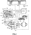
- an intake manifold 11 and an exhaust manifold 12 of a diesel engine 10 is connected to a compressor 14 and a turbine 15 of a supercharger 13, respectively.
- the air from an upstream-side air-intake passage 16a is boosted by the compressor 14, cooled by passing through an intercooler 17 provided in a downstream-side air-intake passage 16b, and supplied to the diesel engine 10 from the intake manifold 11 via an intake throttle valve 18.
- the exhaust gas from the diesel engine 10 is exhausted into an exhaust pipe 20 after driving the turbine 15.
- An air mass flow sensor (MAF) 19 for measuring the intake air volume is provided to the upstream-side air-intake passage 16a in order to control the opening of the intake throttle valve 18 and regulate the intake air volume.
- the exhaust pipe 20 and the upstream-side air-intake passage 16a are connected to an EGR (Exhaust Gas Recirculation) passage 21 for returning a portion of the exhaust gas back into the intake system of the engine 10 to reduce NOx, and the EGR passage 21 is connected to an EGR cooler 22 and an EGR valve 23.
- EGR exhaust Gas Recirculation
- the exhaust pipe 20 is connected to an exhaust brake valve 24, a DPD 25, an exhaust throttle valve 26, and a silencer 27.
- the DPD 25 includes a DOC 28 formed of an active catalyst that oxidizes an unburned fuel, and a CSF (Catalyzed Soot Filter) 29 that traps PM contained in the exhaust gas.
- a CSF Catalyzed Soot Filter
- an SCR device for denitrating NOx by ammonia is also connected between the exhaust throttle valve 26 and the silencer 27.
- exhaust gas temperature sensors 30a and 30b provided at the front and back of the DOC 28 and a differential pressure sensor 31 that detects the amount of the PM accumulated in the CSF 29. These detected values are input into an ECU (Engine Control Unit) 32.
- ECU Engine Control Unit
- Input into the ECU 32 are values detected by an engine speed sensor 33 for detecting the engine speed, a vehicle speed sensor 34, and an atmospheric pressure sensor 35.
- the ECU 32 controls the quantity of the fuel injected from a fuel injector 38 according to the degree of opening of an accelerator, and controls the intake throttle valve 18, the exhaust brake valve 24, and the exhaust throttle valve 26 as appropriate.
- the ECU 32 is adapted to regenerate the DPD by raising the temperature of the exhaust gas from the diesel engine 10 to 600°C and combusting the PM, when it is determined that a certain amount of the PM has been accumulated in the DPD 25 by the value detected by the differential pressure sensor 31 that detects the differential pressure between the front and the back of the CSF 29, or when a distance traveled since the last regeneration has reached a predetermined value.
- the fuel injector 38 performs multi-injection (pilot injection, pre-injection, main injection, and after-injection) to raise the temperature of the exhaust gas to a catalyst activation temperature of the DOC 28 or higher and thereafter proceeds to post-injection in order to raise the temperature of the exhaust gas to 600°C and combust the PM.
- multi-injection pilot injection, pre-injection, main injection, and after-injection
- the manual regeneration is adopted to reduce the dilution amount of lubricant oil produced when the fuel oil is mixed into the lubricant oil in a cylinder by the post-injection.
- the ECU 32 regenerates the DPD 25 by throttling the intake throttle valve 18, closing the EGR valve 23, and performing the multi-injection to raise the temperature of the exhaust gas to 250°C or the catalyst activation temperature of the DOC 28, followed by the post-injection in addition to the multi-injection in order to raise the temperature of the exhaust gas to 600°C and combust the PM.
- the intake throttle valve 18 and the EGR valve 23 are subjected back to the normal control after the regeneration is completed.
- the ECU 32 turns on an automatic regeneration alarm lamp 36b during the automatic regeneration.
- the ECU 32 gives a manual regeneration alarm by blinking a manual regeneration alarm lamp 36a.
- a driver stops the vehicle and presses a DPD manual regeneration execution switch 37 to start the manual regeneration.
- the ECU 32 regenerates the DPD 25 by increasing the engine speed from an idle speed, throttling the intake throttle valve 18, closing the EGR valve 23 and the exhaust brake valve 24, and performing the multi-injection to raise the temperature of the exhaust gas to the catalyst activation temperature or higher.
- the ECU 32 opens the exhaust brake valve 24, closes the exhaust throttle valve 26, and adds the post-injection to the multi-injection in order to raise the temperature of the exhaust gas to 600°C and combust the PM.
- the aforementioned automatic regeneration is the regeneration mode when the vehicles travels at the altitudes of 0 to 2000 m in the normal drive mode.
- the automatic regeneration an upland regeneration mode
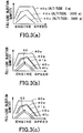
- a map of the full-load injection quantities of the fuel corresponding to the engine speed is stored in the ECU 32 for each altitude (altitudes of 0 m, 2000 m, and 3000 m, for example).
- 40a represents a full-load performance characteristic line of the engine speed and the full-load injection quantity at the altitude of 0 m
- 40b represents a full-load performance characteristic line of the engine speed and the full-load injection quantity at the altitude of 2000 m
- 40c represents a full-load performance characteristic line of the engine speed and the full-load injection quantity at the altitude of 3000 m.
- the ECU 32 determines the full-load injection quantity of the fuel from the altitude based on the engine speed detected by the engine speed sensor 33 and the atmospheric pressure detected by the atmospheric pressure sensor 35 and drives the vehicle, such that the vehicle can obtain the maximum engine performance according to the oxygen concentration when traveling at the altitudes of 2000 m and 3000 m in the upland normal mode.
- the ECU 32 determines the altitude at which the vehicle is traveling on the basis of the atmospheric pressure detected by the atmospheric pressure sensor 35 and drives the vehicle in the upland normal drive mode on the basis of the full-load performance characteristic lines 40b and 40c in the map of Fig. 3(a) . Altitudes between 2000 m and 3000 m would be interpolated as appropriate on the basis of the full-load performance characteristic lines 40b and 40c to determine the full-load injection quantity.
- the ECU 32 determines the upland drive regeneration injection quantity decreased from the upland full-load injection quantity on the basis of the quantity required for the post-injection.
- Figs. 3(b) and 3(c) illustrate upland regeneration drive characteristic lines 41b and 41c obtained by subtracting the quantity required for the post-injection from the full-load performance characteristic lines 40b and 40c at the altitudes of 2000 m and 3000 m.
- the ECU 32 determines the upland regeneration drive injection quantity from the engine speed on the basis of the upland regeneration drive characteristic lines 41b and 41c to drive the vehicle.
- the injection quantity of the fuel is gradually decreased from the upland full-load injection quantity down to the upland drive regeneration injection quantity as indicated by an arrow 42, thereby improving the drivability.
- the injection quantity of the fuel is preferably decreased during the multi-injection because, as described above, the regeneration operation is performed by raising the temperature of the exhaust gas to the catalyst activation temperature or higher by the multi-injection for a few minutes at the beginning of the regeneration and thereafter raising the temperature of the exhaust gas to 600°C by the post-injection.
- the decreased fuel quantity is used in the post-injection to perform the regeneration operation.
- the vehicle is switched back to the upland normal drive mode by shifting from the upland regeneration drive characteristic lines 41b and 41c to the full-load performance characteristic lines 40b and 40c, as illustrated in Fig. 3(c) .
- the injection quantity of the fuel is gradually increased back to the upland full-load injection quantity as indicated by an arrow 43 so as not to cause abrupt torque fluctuation upon switching.
- the vehicle travels in the normal drive mode about 95% of the time and in the regeneration mode about 5% of the time.
- the normal drive mode performed 95% of the time with the maximum engine performance and gradually degrading it to be the engine performance of the drive mode in the regeneration mode at the time of regeneration, it would be possible to secure and remarkably improve the engine performance in the upland normal drive mode rather than determining the full-load injection quantity in the normal drive mode in consideration of the quantity required for the post-injection in the regeneration mode performed 5% of the time as conventionally performed.
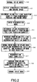
- Fig. 2 is a flowchart illustrating a control flow of the ECU 32 that switches the mode from the normal drive mode to the regeneration mode in the aforementioned exhaust gas treatment system.
- the atmospheric pressure and the engine speed are detected (51) while the vehicle is in motion in the drive mode (50).
- the upland full-load injection quantity is determined (52) from the full-load performance characteristic lines 40b and 40c in the map illustrated in Fig. 3(a) so that the vehicle travels in the upland normal drive mode.
- the ECU 32 enters the regeneration mode (53) and determines the upland drive regeneration injection quantity (54) on the basis of the upland regeneration drive characteristic lines 41b and 41c from the upland full-load injection quantity based on the full-load performance characteristic lines 40b and 40c illustrated in Fig. 3(b) .
- the ECU 32 then decreases the injection quantity of the fuel from the upland full-load injection quantity to the upland drive regeneration injection quantity (55) and, with the upland drive regeneration injection quantity, drives the vehicle in the upland normal drive mode and operates the regeneration mode by the post-injection (56). Once the operation of the regeneration mode is completed (57), the post-injection is stopped, the injection quantity of the fuel is increased from the upland drive regeneration injection quantity to the upland full-load injection quantity (58), and the vehicle is switched back to the normal drive mode (50).
- the present invention can improve the full-load performance by driving the vehicle with the upland full-load injection quantity with which the maximum engine performance based on the atmospheric pressure can be obtained, when driving in the upland area in the normal drive mode.
- the injection quantity of the fuel is set equal to the upland regeneration drive injection quantity obtained by subtracting the quantity required for the post-injection from the upland full-load injection quantity, whereby the DPD is regenerated without difficulty.
Landscapes
- Engineering & Computer Science (AREA)
- Chemical & Material Sciences (AREA)
- Combustion & Propulsion (AREA)
- Mechanical Engineering (AREA)
- General Engineering & Computer Science (AREA)
- Processes For Solid Components From Exhaust (AREA)
- Electrical Control Of Air Or Fuel Supplied To Internal-Combustion Engine (AREA)
- Exhaust Gas After Treatment (AREA)
- Combined Controls Of Internal Combustion Engines (AREA)
Description
- The present invention relates to an exhaust gas purification system that traps PM (Particulate Matter) contained in exhaust gas from a diesel engine as well as exhausts NOx upon purification. Particularly, the present invention relates to an exhaust gas purification system in an upland area that can regenerate a DPD without degrading normal drive performance in an upland area.
- As the exhaust gas purification system that purifies and exhausts the exhaust gas from the diesel engine, there has been developed an exhaust gas purification system in which DPD (Diesel Particulate Defuser) and SCR (Selective Catalytic Reduction) devices are connected to an exhaust pipe.
- In this exhaust gas purification system, the DPD traps the PM contained in the exhaust gas. Moreover, in the exhaust gas purification system, an SCR system including the SCR device supplies an aqueous urea solution stored in a urea tank to the upstream of the exhaust gas in the SCR to generate ammonia by the heat of the exhaust gas. NOx is reduced by the ammonia on an SCR catalyst and purified (refer to Patent Documents 1 and 2, for example).
- The PM trapped and accumulated in the DPD needs to be oxidized and removed to regenerate the DPD as appropriate in order to prevent clogging in a filter.
- The clogging is detected by an exhaust pressure sensor that detects the differential pressure between the front and the back of the DPD. When the differential pressure has reached the upper limit, an ECU (Engine Control Unit) starts regenerating the DPD either automatically or manually. In the manual regeneration, the DPD starts regenerating once the ECU has turned on a DPD alarm lamp provided in a cabin and a driver has pressed a regeneration execution switch.
- The DPD is regenerated by performing multi-injection of a fuel (pilot injection, pre-injection, main injection, and after-injection) to raise the exhaust temperature equal to or higher than a catalyst activation temperature of the DPD, followed by post-injection in addition to the multi-injection to raise the exhaust temperature up to approximately 600°C, thereby combusting and removing the PM trapped in the DPD by the high-temperature exhaust gas.
- The DPD is regenerated automatically while a vehicle is in motion. Hence, the drive performance is determined by a full-load injection quantity of the fuel that is set intentionally low in a normal drive mode in consideration of a fuel quantity to be injected by the post-injection at the time of regeneration.
- Now, when the vehicle travels at high altitudes of 2000 m and 3000 m where the air (oxygen) is thin, the atmospheric pressure is reduced to approximately 80 kPa (at 2000 m) and approximately 70 kPa (at 3000 m) as compared to approximately 100 kPa at an altitude of 0 m, thereby requiring engine performance at full load to be degraded.
- Document
EP 1 245 813 A2 discloses an exhaust gas purification system according to the preamble of claim 1. This system gradually decreases a main injection quantity and simultaneously gradually increases a post injection quantity during a given time period. -
- Patent Document 1: Japanese Patent Application Publication No.
2000- 303826 - Patent Document 2: Japanese Patent No.
4175281 - In order to improve drivability of the vehicle traveling in the upland area in the normal drive mode, it is preferable to improve the engine performance. However, when a turbo vehicle attempts to improve full-load performance in the upland area by increasing supercharging pressure, the supercharging pressure would increase relatively to the atmospheric pressure in the upland area, thereby causing excessive rotation of a turbine and possible damage thereto. Thus, the absolute supercharging pressure is typically decreased. When it is attempted to increase the full-load injection quantity of the fuel to improve the engine performance in the upland area where oxygen is thin, there would be a problem in which, when the DPD is to be regenerated (in a regeneration mode), an air-fuel ratio is decreased to the extent that there is not enough oxygen left in the gas after in-cylinder combustion to perform the post-injection, whereby the regeneration would not be completed (the temperature of the exhaust gas would not be increased sufficiently).
- Accordingly, the engine performance in the normal drive mode needs to be set in consideration of the case where the DPD is regenerated in the upland area. When the full-load injection quantity is set in consideration of the post-injection performed at the time of regenerating the DPD, however, there is a problem that the engine performance in the upland area would be degraded. Such request for the engine performance in the upland area is directly linked to marketability, and thus it is required to maintain the performance as much as possible.
- Now, in the normal drive mode, the full-load injection quantity of the fuel can be set in the condition where there is near a theoretical air-fuel ratio, and can be divided into the quantity for driving and the quantity for the post-injection when the vehicle is in the regeneration mode. However, there would be an abrupt decrease in torque when the vehicle enters the regeneration mode and an abrupt increase in the torque when the regeneration is completed, thereby greatly impairing the drivability.
- Accordingly, an object of the present invention is to solve the aforementioned problems and to provide the exhaust gas purification system in an upland area capable of maintaining the engine performance when the vehicle travels in the upland area in the normal drive mode, securing the amount of oxygen required for the post-injection in the regeneration mode, and switching between the normal mode and the regeneration mode without incongruity.
- To achieve the object described above, an invention of claim 1 provides an exhaust gas purification system in an upland area, including: a DPD connected to an exhaust pipe of a diesel engine for trapping PM contained in exhaust gas, the exhaust gas purification system having a regeneration mode for automatically regenerating the DPD by performing multi-injection and post-injection to raise a temperature of the exhaust gas from the diesel engine when an amount of the PM in the DPD has reached a certain amount or more during a normal drive mode, characterized in that the exhaust gas purification system determines an upland full-load injection quantity from atmospheric pressure in an upland area and an engine speed when a vehicle is in motion in the normal drive mode in the upland area and drives the vehicle with the injection quantity determined, determines an upland drive regeneration injection quantity obtained by decreasing the upland full-load injection quantity on the basis of a quantity required for the post-injection when the vehicle is in the regeneration mode, gradually decreases an injection quantity from the upland full-load injection quantity to the upland regeneration drive injection quantity when the vehicle switches from the normal drive mode in the upland area to an upland regeneration mode and, by using the decreased quantity for the post-injection, increases the injection quantity from the upland regeneration drive injection quantity to the upland full-load injection quantity after the regeneration is completed.
- An invention of claim 2 provides the exhaust gas purification system in an upland area according to claim 1, including a map in which a full-load injection quantity of a fuel corresponding to the engine speed is set on the basis of an air-fuel ratio for each atmospheric pressure in the upland area, wherein the upland full-load injection quantity required in the normal drive mode in the upland area is determined by the map on the basis of the atmospheric pressure at the altitude in the upland area and the engine speed while the vehicle is in motion.
- An invention of
claim 3 provides the exhaust gas purification system in an upland area according to claim 2, wherein the upland full-load injection quantity required in the normal drive mode in the upland area is determined by the engine speed on the basis of a full-load performance characteristic line that is based on the altitude and selected from the map. - An invention of claim 4 provides the exhaust gas purification system in an upland area according to any of claims 1 to 3, wherein, during the regeneration mode, the temperature of the exhaust gas is raised to a catalyst activation temperature of the DPD or higher by performing the multi-injection while decreasing the upland full-load injection quantity to the upland regeneration drive injection quantity to be used in the normal drive mode, and a difference between the upland regeneration drive injection quantity and the upland full-load injection quantity is allotted to the post-injection.
- The present invention can exert superior effects in which: the vehicle travels with an upland full-load injection quantity with which the maximum engine performance can be obtained based on the atmospheric pressure when traveling in the normal drive mode in the upland area; the DPD can be regenerated without difficulty by traveling with an upland regeneration drive injection quantity when the vehicle is in the regeneration mode, the upland regeneration drive injection quantity being equal to the upland full-load injection quantity minus the quantity required for the post-injection; and the injection quantity of the fuel is decreased from the upland full-load injection quantity down to the upland regeneration drive injection quantity when the vehicle starts regenerating and increased back to the upland full-load injection quantity after the regeneration is completed, thereby causing no abrupt change in the torque and retaining excellent drivability.
-
-
Fig. 1 is an overall structural diagram illustrating an embodiment of the present invention; -
Fig. 2 is a flowchart illustrating a control flow of the present invention; and -
Figs. 3(a) to 3(c) are graphs illustrating a relationship between an engine speed and the full-load injection quantity at each altitude of the present invention where the vehicle is in: (a) the normal drive mode; (b) a decrease mode during which the vehicle shifts from the normal drive mode to the regeneration mode; and (c) an increase mode during which the vehicle returns to the normal drive mode upon completion of the regeneration mode. - A preferred embodiment of the present invention will be described below in detail with reference to the attached drawings.
- As illustrated in
Fig. 1 , anintake manifold 11 and anexhaust manifold 12 of adiesel engine 10 is connected to a compressor 14 and a turbine 15 of a supercharger 13, respectively. The air from an upstream-side air-intake passage 16a is boosted by the compressor 14, cooled by passing through anintercooler 17 provided in a downstream-side air-intake passage 16b, and supplied to thediesel engine 10 from theintake manifold 11 via anintake throttle valve 18. The exhaust gas from thediesel engine 10 is exhausted into anexhaust pipe 20 after driving the turbine 15. - An air mass flow sensor (MAF) 19 for measuring the intake air volume is provided to the upstream-side air-intake passage 16a in order to control the opening of the
intake throttle valve 18 and regulate the intake air volume. In addition, theexhaust pipe 20 and the upstream-side air-intake passage 16a are connected to an EGR (Exhaust Gas Recirculation)passage 21 for returning a portion of the exhaust gas back into the intake system of theengine 10 to reduce NOx, and theEGR passage 21 is connected to anEGR cooler 22 and anEGR valve 23. - The
exhaust pipe 20 is connected to anexhaust brake valve 24, aDPD 25, anexhaust throttle valve 26, and asilencer 27. The DPD 25 includes aDOC 28 formed of an active catalyst that oxidizes an unburned fuel, and a CSF (Catalyzed Soot Filter) 29 that traps PM contained in the exhaust gas. Although not shown in the figure, an SCR device for denitrating NOx by ammonia is also connected between theexhaust throttle valve 26 and thesilencer 27. - Also provided are exhaust
gas temperature sensors 30a and 30b provided at the front and back of theDOC 28 and adifferential pressure sensor 31 that detects the amount of the PM accumulated in theCSF 29. These detected values are input into an ECU (Engine Control Unit) 32. - Input into the
ECU 32 are values detected by anengine speed sensor 33 for detecting the engine speed, avehicle speed sensor 34, and anatmospheric pressure sensor 35. - While the vehicle is in motion, the
ECU 32 controls the quantity of the fuel injected from afuel injector 38 according to the degree of opening of an accelerator, and controls theintake throttle valve 18, theexhaust brake valve 24, and theexhaust throttle valve 26 as appropriate. - In this exhaust gas treatment system, the
ECU 32 is adapted to regenerate the DPD by raising the temperature of the exhaust gas from thediesel engine 10 to 600°C and combusting the PM, when it is determined that a certain amount of the PM has been accumulated in theDPD 25 by the value detected by thedifferential pressure sensor 31 that detects the differential pressure between the front and the back of theCSF 29, or when a distance traveled since the last regeneration has reached a predetermined value. - In this regeneration, the
fuel injector 38 performs multi-injection (pilot injection, pre-injection, main injection, and after-injection) to raise the temperature of the exhaust gas to a catalyst activation temperature of theDOC 28 or higher and thereafter proceeds to post-injection in order to raise the temperature of the exhaust gas to 600°C and combust the PM. Although the DPD is normally regenerated automatically while the vehicle is in motion, the manual regeneration is adopted to reduce the dilution amount of lubricant oil produced when the fuel oil is mixed into the lubricant oil in a cylinder by the post-injection. - In the automatic regeneration, the
ECU 32 regenerates theDPD 25 by throttling theintake throttle valve 18, closing theEGR valve 23, and performing the multi-injection to raise the temperature of the exhaust gas to 250°C or the catalyst activation temperature of theDOC 28, followed by the post-injection in addition to the multi-injection in order to raise the temperature of the exhaust gas to 600°C and combust the PM. Theintake throttle valve 18 and theEGR valve 23 are subjected back to the normal control after the regeneration is completed. TheECU 32 turns on an automatic regeneration alarm lamp 36b during the automatic regeneration. - In the manual regeneration, the
ECU 32 gives a manual regeneration alarm by blinking a manual regeneration alarm lamp 36a. In response to this alarm, a driver stops the vehicle and presses a DPD manualregeneration execution switch 37 to start the manual regeneration. - In the manual regeneration, the
ECU 32 regenerates theDPD 25 by increasing the engine speed from an idle speed, throttling theintake throttle valve 18, closing theEGR valve 23 and theexhaust brake valve 24, and performing the multi-injection to raise the temperature of the exhaust gas to the catalyst activation temperature or higher. After raising the temperature, theECU 32 opens theexhaust brake valve 24, closes theexhaust throttle valve 26, and adds the post-injection to the multi-injection in order to raise the temperature of the exhaust gas to 600°C and combust the PM. - The aforementioned automatic regeneration is the regeneration mode when the vehicles travels at the altitudes of 0 to 2000 m in the normal drive mode. When the automatic regeneration (an upland regeneration mode) is attempted at the altitude beyond 2000 m, however, there would be less oxygen available for the post-injection.
- Now, as illustrated in
Fig. 3(a) , a map of the full-load injection quantities of the fuel corresponding to the engine speed is stored in theECU 32 for each altitude (altitudes of 0 m, 2000 m, and 3000 m, for example). InFig. 3(a) , 40a represents a full-load performance characteristic line of the engine speed and the full-load injection quantity at the altitude of 0 m, 40b represents a full-load performance characteristic line of the engine speed and the full-load injection quantity at the altitude of 2000 m, and 40c represents a full-load performance characteristic line of the engine speed and the full-load injection quantity at the altitude of 3000 m. - As illustrated in the map of
Fig. 3(a) , theECU 32 determines the full-load injection quantity of the fuel from the altitude based on the engine speed detected by theengine speed sensor 33 and the atmospheric pressure detected by theatmospheric pressure sensor 35 and drives the vehicle, such that the vehicle can obtain the maximum engine performance according to the oxygen concentration when traveling at the altitudes of 2000 m and 3000 m in the upland normal mode. - The
ECU 32 determines the altitude at which the vehicle is traveling on the basis of the atmospheric pressure detected by theatmospheric pressure sensor 35 and drives the vehicle in the upland normal drive mode on the basis of the full-load performance characteristic lines 40b and 40c in the map ofFig. 3(a) . Altitudes between 2000 m and 3000 m would be interpolated as appropriate on the basis of the full-load performance characteristic lines 40b and 40c to determine the full-load injection quantity. - When the vehicle switches to the regeneration mode while traveling in the upland normal drive mode, the fuel injected by the post-injection cannot be combusted due to the lack of oxygen, the regeneration mode regenerating the
DPD 25 automatically. Therefore, theECU 32 determines the upland drive regeneration injection quantity decreased from the upland full-load injection quantity on the basis of the quantity required for the post-injection. -
Figs. 3(b) and 3(c) illustrate upland regeneration drivecharacteristic lines 41b and 41c obtained by subtracting the quantity required for the post-injection from the full-load performance characteristic lines 40b and 40c at the altitudes of 2000 m and 3000 m. In the regeneration mode, theECU 32 determines the upland regeneration drive injection quantity from the engine speed on the basis of the upland regeneration drivecharacteristic lines 41b and 41c to drive the vehicle. - At this time, the engine performance of the vehicle in motion would be degraded abruptly when the upland full-load injection quantity is directly decreased to the upland drive regeneration injection quantity. Hence, as illustrated in
Fig. 3(b) , the injection quantity of the fuel is gradually decreased from the upland full-load injection quantity down to the upland drive regeneration injection quantity as indicated by anarrow 42, thereby improving the drivability. - The injection quantity of the fuel is preferably decreased during the multi-injection because, as described above, the regeneration operation is performed by raising the temperature of the exhaust gas to the catalyst activation temperature or higher by the multi-injection for a few minutes at the beginning of the regeneration and thereafter raising the temperature of the exhaust gas to 600°C by the post-injection.
- After the injection quantity of the fuel at the time of normal drive has been decreased from the upland full-load injection quantity to the upland drive regeneration injection quantity, the decreased fuel quantity is used in the post-injection to perform the regeneration operation.
- Once the
DPD 25 has been regenerated by the regeneration operation, the vehicle is switched back to the upland normal drive mode by shifting from the upland regeneration drivecharacteristic lines 41b and 41c to the full-load performance characteristic lines 40b and 40c, as illustrated inFig. 3(c) . At this time, the injection quantity of the fuel is gradually increased back to the upland full-load injection quantity as indicated by anarrow 43 so as not to cause abrupt torque fluctuation upon switching. - The vehicle travels in the normal drive mode about 95% of the time and in the regeneration mode about 5% of the time. By operating the normal drive mode performed 95% of the time with the maximum engine performance and gradually degrading it to be the engine performance of the drive mode in the regeneration mode at the time of regeneration, it would be possible to secure and remarkably improve the engine performance in the upland normal drive mode rather than determining the full-load injection quantity in the normal drive mode in consideration of the quantity required for the post-injection in the regeneration mode performed 5% of the time as conventionally performed.
-
Fig. 2 is a flowchart illustrating a control flow of theECU 32 that switches the mode from the normal drive mode to the regeneration mode in the aforementioned exhaust gas treatment system. - As illustrated in
Fig. 2 , the atmospheric pressure and the engine speed are detected (51) while the vehicle is in motion in the drive mode (50). On the basis of the detected values, the upland full-load injection quantity is determined (52) from the full-load performance characteristic lines 40b and 40c in the map illustrated inFig. 3(a) so that the vehicle travels in the upland normal drive mode. When the certain amount of the PM has been accumulated in the DPD, theECU 32 enters the regeneration mode (53) and determines the upland drive regeneration injection quantity (54) on the basis of the upland regeneration drivecharacteristic lines 41b and 41c from the upland full-load injection quantity based on the full-load performance characteristic lines 40b and 40c illustrated inFig. 3(b) . TheECU 32 then decreases the injection quantity of the fuel from the upland full-load injection quantity to the upland drive regeneration injection quantity (55) and, with the upland drive regeneration injection quantity, drives the vehicle in the upland normal drive mode and operates the regeneration mode by the post-injection (56). Once the operation of the regeneration mode is completed (57), the post-injection is stopped, the injection quantity of the fuel is increased from the upland drive regeneration injection quantity to the upland full-load injection quantity (58), and the vehicle is switched back to the normal drive mode (50). - As described above, the present invention can improve the full-load performance by driving the vehicle with the upland full-load injection quantity with which the maximum engine performance based on the atmospheric pressure can be obtained, when driving in the upland area in the normal drive mode. Moreover, when the regeneration mode is operated during the upland normal drive, the injection quantity of the fuel is set equal to the upland regeneration drive injection quantity obtained by subtracting the quantity required for the post-injection from the upland full-load injection quantity, whereby the DPD is regenerated without difficulty. At the same time, there would be no abrupt change in the torque by decreasing the injection quantity from the upland full-load injection quantity to the upland regeneration drive injection quantity at the beginning of the regeneration and by increasing the injection quantity back to the upland full-load injection quantity after completing the regeneration, thereby maintaining the excellent drivability.
-
- 10
- diesel engine
- 20
- exhaust pipe
- 25
- DPD
- 32
- ECU
- 33
- engine speed sensor
- 35
- atmospheric pressure sensor
Claims (4)
- An exhaust gas purification system in an upland area, comprising:a DPD (25) connected to an exhaust pipe (20) of a diesel engine (10) for trapping PM contained in exhaust gas,the exhaust gas purification system having a regeneration mode for automatically regenerating the DPD (25) by performing multi-injection and post-injection to raise a temperature of the exhaust gas from the diesel engine (10) when an amount of the PM in the DPD (25) has reached a certain amount or more during a normal drive mode,characterized in that the exhaust gas purification system determines an upland full-load injection quantity from atmospheric pressure in an upland area and an engine speed when a vehicle is in motion in the normal drive mode in the upland area and drives the vehicle with the injection quantity determined, determines an upland drive regeneration injection quantity obtained by decreasing the upland full-load injection quantity on the basis of a quantity required for the post-injection when the vehicle is in the regeneration mode, gradually decreases an injection quantity from the upland full-load injection quantity to the upland regeneration drive injection quantity when the vehicle switches from the normal drive mode in the upland area to an upland regeneration mode, injects a fuel of the decreased quantity by starting the post-injection after the gradually decreased upland full-load injection quantity falls to the upland regeneration drive injection quantity, and increases the injection quantity from the upland regeneration drive injection quantity to the upland full-load injection quantity after the regeneration is completed.
- The exhaust gas purification system in an upland area according to claim 1, comprising a map in which a full-load injection quantity of a fuel corresponding to the engine speed is set on the basis of an air-fuel ratio for each atmospheric pressure in the upland area,
wherein the upland full-load injection quantity required in the normal drive mode in the upland area is determined by the map on the basis of the atmospheric pressure at the altitude in the upland area and the engine speed while the vehicle is in motion. - The exhaust gas purification system in an upland area according to claim 2, wherein the upland full-load injection quantity required in the normal drive mode in the upland area is determined by the engine speed on the basis of a full-load performance characteristic line that is based on the altitude and selected from the map.
- The exhaust gas purification system in an upland area according to any of claims 1 to 3, wherein, during the regeneration mode, the temperature of the exhaust gas is raised to a catalyst activation temperature of the DPD or higher by performing the multi-injection while decreasing the upland full-load injection quantity to the upland regeneration drive injection quantity, and a difference between the upland regeneration drive injection quantity and the upland full-load injection quantity is allotted to the post-injection.
Applications Claiming Priority (2)
| Application Number | Priority Date | Filing Date | Title |
|---|---|---|---|
| JP2010119717A JP5625489B2 (en) | 2010-05-25 | 2010-05-25 | Exhaust gas purification system at high altitude |
| PCT/JP2011/061216 WO2011148813A1 (en) | 2010-05-25 | 2011-05-16 | System for purifying exhaust gas in upland area |
Publications (3)
| Publication Number | Publication Date |
|---|---|
| EP2578824A1 EP2578824A1 (en) | 2013-04-10 |
| EP2578824A4 EP2578824A4 (en) | 2018-03-28 |
| EP2578824B1 true EP2578824B1 (en) | 2020-03-25 |
Family
ID=45003804
Family Applications (1)
| Application Number | Title | Priority Date | Filing Date |
|---|---|---|---|
| EP11786512.1A Active EP2578824B1 (en) | 2010-05-25 | 2011-05-16 | System for purifying exhaust gas in upland area |
Country Status (5)
| Country | Link |
|---|---|
| US (1) | US8925306B2 (en) |
| EP (1) | EP2578824B1 (en) |
| JP (1) | JP5625489B2 (en) |
| CN (1) | CN102906381B (en) |
| WO (1) | WO2011148813A1 (en) |
Families Citing this family (2)
| Publication number | Priority date | Publication date | Assignee | Title |
|---|---|---|---|---|
| KR101801501B1 (en) * | 2013-12-17 | 2017-12-20 | 우수이 고쿠사이 산교 가부시키가이샤 | Exhaust gas purification device for marine diesel engine that uses low-quality fuel such as heavy oil containing high concentration of sulfur component |
| CN111350597B (en) * | 2020-03-25 | 2022-05-20 | 重庆康明斯发动机有限公司 | Control method and control system for automobile exhaust emission and vehicle |
Family Cites Families (21)
| Publication number | Priority date | Publication date | Assignee | Title |
|---|---|---|---|---|
| JPH04175281A (en) | 1990-11-09 | 1992-06-23 | Nippon Chem Ind Co Ltd | Glazed molded article of cement having transfer decoration and production thereof |
| JP2000303826A (en) | 1999-04-16 | 2000-10-31 | Isuzu Motors Ltd | Exhaust emission control device for diesel engine |
| JP2002115584A (en) * | 2000-10-03 | 2002-04-19 | Denso Corp | Fuel injection control device for internal combustion engine |
| JP3975680B2 (en) * | 2001-02-06 | 2007-09-12 | 日産自動車株式会社 | Control device for internal combustion engine |
| JP3838338B2 (en) * | 2001-03-27 | 2006-10-25 | 三菱ふそうトラック・バス株式会社 | Exhaust gas purification device for internal combustion engine |
| EP1291513B1 (en) * | 2001-09-07 | 2010-11-10 | Mitsubishi Jidosha Kogyo Kabushiki Kaisha | Exhaust emission control device of engine |
| JP2004218440A (en) * | 2003-01-09 | 2004-08-05 | Toyota Motor Corp | Exhaust emission control device for internal combustion engine |
| JP2004245175A (en) * | 2003-02-17 | 2004-09-02 | Isuzu Motors Ltd | Controlling method for engine air-fuel ratio |
| CN1701171B (en) * | 2003-07-08 | 2010-11-24 | 日产自动车株式会社 | Combustion control for engine |
| JP4038187B2 (en) * | 2004-03-11 | 2008-01-23 | トヨタ自動車株式会社 | Particulate matter regeneration control device for internal combustion engine exhaust purification device |
| JP4175281B2 (en) | 2004-03-31 | 2008-11-05 | いすゞ自動車株式会社 | Exhaust gas purification system control method and exhaust gas purification system |
| JP4432745B2 (en) * | 2004-11-19 | 2010-03-17 | 三菱自動車工業株式会社 | Exhaust gas purification device for internal combustion engine |
| US7343735B2 (en) * | 2005-05-02 | 2008-03-18 | Cummins, Inc. | Apparatus and method for regenerating an exhaust gas aftertreatment component of an internal combustion engine |
| JP3933172B2 (en) * | 2005-07-15 | 2007-06-20 | いすゞ自動車株式会社 | Exhaust gas purification system control method and exhaust gas purification system |
| JP3956992B1 (en) * | 2006-01-27 | 2007-08-08 | いすゞ自動車株式会社 | Exhaust gas purification method and exhaust gas purification system |
| FR2899644B1 (en) * | 2006-04-11 | 2008-07-18 | Peugeot Citroen Automobiles Sa | SYSTEM AND METHOD FOR AIDING THE REGENERATION OF A PARTICLE FILTER AGENT IN AN EXHAUST LINE OF A DIESEL ENGINE OF A MOTOR VEHICLE. |
| JP2008121518A (en) * | 2006-11-10 | 2008-05-29 | Toyota Motor Corp | Exhaust emission control device of internal combustion engine |
| FR2909123B1 (en) * | 2006-11-27 | 2012-10-05 | Peugeot Citroen Automobiles Sa | GAS EXHAUST LINE FOR INTERNAL COMBUSTION ENGINE EQUIPPED WITH DETERMINATION SYSTEMS. |
| JP4710815B2 (en) | 2006-12-14 | 2011-06-29 | トヨタ自動車株式会社 | Exhaust gas purification device for internal combustion engine |
| JP2008309080A (en) * | 2007-06-15 | 2008-12-25 | Denso Corp | Exhaust emission control device for internal combustion engine |
| US8407989B2 (en) * | 2010-04-06 | 2013-04-02 | Caterpillar Inc. | Regeneration strategy for engine exhaust |
-
2010
- 2010-05-25 JP JP2010119717A patent/JP5625489B2/en not_active Expired - Fee Related
-
2011
- 2011-05-16 US US13/699,503 patent/US8925306B2/en active Active
- 2011-05-16 CN CN201180025598.4A patent/CN102906381B/en active Active
- 2011-05-16 WO PCT/JP2011/061216 patent/WO2011148813A1/en active Application Filing
- 2011-05-16 EP EP11786512.1A patent/EP2578824B1/en active Active
Non-Patent Citations (1)
| Title |
|---|
| None * |
Also Published As
| Publication number | Publication date |
|---|---|
| JP2011247139A (en) | 2011-12-08 |
| WO2011148813A1 (en) | 2011-12-01 |
| EP2578824A1 (en) | 2013-04-10 |
| CN102906381B (en) | 2015-07-29 |
| CN102906381A (en) | 2013-01-30 |
| EP2578824A4 (en) | 2018-03-28 |
| US8925306B2 (en) | 2015-01-06 |
| US20130061582A1 (en) | 2013-03-14 |
| JP5625489B2 (en) | 2014-11-19 |
Similar Documents
| Publication | Publication Date | Title |
|---|---|---|
| US8307629B2 (en) | Control method of exhaust emission purification system and exhaust emission purification system | |
| US9067160B2 (en) | Exhaust gas purification system | |
| JP2006029239A (en) | Exhaust emission control filter overheat prevention device | |
| JP4314135B2 (en) | Exhaust gas purification device for in-vehicle internal combustion engine | |
| US9034065B2 (en) | Exhaust gas purification system | |
| JP5440385B2 (en) | Exhaust gas purification system | |
| US8978365B2 (en) | Exhaust gas purification system | |
| US10174702B2 (en) | Regeneration device for exhaust-gas purifying device | |
| WO2011155587A1 (en) | Dpf system | |
| US7963101B2 (en) | Exhaust gas purifying device for an internal combustion engine | |
| EP2792865A1 (en) | Diesel engine exhaust gas purification method and exhaust gas purification system | |
| JP5914963B2 (en) | Exhaust gas purification system at high altitude | |
| US20160195030A1 (en) | Exhaust gas purification system of internal combustion engine and exhaust gas purification method of internal combustion engine | |
| EP2578824B1 (en) | System for purifying exhaust gas in upland area | |
| JP2010116817A (en) | Exhaust emission control device of engine | |
| JP6405858B2 (en) | DPF regeneration system for vehicles with PTO device | |
| JP2007040223A (en) | Exhaust emission control device | |
| JP2013194516A (en) | Exhaust emission control device for internal combustion engine | |
| JP4300985B2 (en) | Diesel engine control device | |
| JP5625476B2 (en) | DPF system | |
| JP2010270726A (en) | Method for regenerating particulate filter | |
| JP2011111995A (en) | Exhaust emission control device |
Legal Events
| Date | Code | Title | Description |
|---|---|---|---|
| PUAI | Public reference made under article 153(3) epc to a published international application that has entered the european phase |
Free format text: ORIGINAL CODE: 0009012 |
|
| 17P | Request for examination filed |
Effective date: 20121220 |
|
| AK | Designated contracting states |
Kind code of ref document: A1 Designated state(s): AL AT BE BG CH CY CZ DE DK EE ES FI FR GB GR HR HU IE IS IT LI LT LU LV MC MK MT NL NO PL PT RO RS SE SI SK SM TR |
|
| DAX | Request for extension of the european patent (deleted) | ||
| REG | Reference to a national code |
Ref country code: DE Ref legal event code: R079 Ref document number: 602011065856 Country of ref document: DE Free format text: PREVIOUS MAIN CLASS: F01N0003020000 Ipc: F01N0003023000 |
|
| RA4 | Supplementary search report drawn up and despatched (corrected) |
Effective date: 20180222 |
|
| RIC1 | Information provided on ipc code assigned before grant |
Ipc: F02D 41/02 20060101ALI20180217BHEP Ipc: F02D 41/40 20060101ALI20180217BHEP Ipc: F01N 3/36 20060101ALI20180217BHEP Ipc: F02D 45/00 20060101ALI20180217BHEP Ipc: F01N 9/00 20060101ALI20180217BHEP Ipc: F01N 3/023 20060101AFI20180217BHEP Ipc: F01N 3/18 20060101ALI20180217BHEP Ipc: F02D 41/04 20060101ALI20180217BHEP Ipc: F02D 41/38 20060101ALI20180217BHEP |
|
| GRAP | Despatch of communication of intention to grant a patent |
Free format text: ORIGINAL CODE: EPIDOSNIGR1 |
|
| STAA | Information on the status of an ep patent application or granted ep patent |
Free format text: STATUS: GRANT OF PATENT IS INTENDED |
|
| INTG | Intention to grant announced |
Effective date: 20191011 |
|
| GRAS | Grant fee paid |
Free format text: ORIGINAL CODE: EPIDOSNIGR3 |
|
| GRAA | (expected) grant |
Free format text: ORIGINAL CODE: 0009210 |
|
| STAA | Information on the status of an ep patent application or granted ep patent |
Free format text: STATUS: THE PATENT HAS BEEN GRANTED |
|
| AK | Designated contracting states |
Kind code of ref document: B1 Designated state(s): AL AT BE BG CH CY CZ DE DK EE ES FI FR GB GR HR HU IE IS IT LI LT LU LV MC MK MT NL NO PL PT RO RS SE SI SK SM TR |
|
| REG | Reference to a national code |
Ref country code: GB Ref legal event code: FG4D |
|
| REG | Reference to a national code |
Ref country code: AT Ref legal event code: REF Ref document number: 1248808 Country of ref document: AT Kind code of ref document: T Effective date: 20200415 Ref country code: IE Ref legal event code: FG4D |
|
| REG | Reference to a national code |
Ref country code: DE Ref legal event code: R096 Ref document number: 602011065856 Country of ref document: DE |
|
| PG25 | Lapsed in a contracting state [announced via postgrant information from national office to epo] |
Ref country code: RS Free format text: LAPSE BECAUSE OF FAILURE TO SUBMIT A TRANSLATION OF THE DESCRIPTION OR TO PAY THE FEE WITHIN THE PRESCRIBED TIME-LIMIT Effective date: 20200325 Ref country code: FI Free format text: LAPSE BECAUSE OF FAILURE TO SUBMIT A TRANSLATION OF THE DESCRIPTION OR TO PAY THE FEE WITHIN THE PRESCRIBED TIME-LIMIT Effective date: 20200325 Ref country code: NO Free format text: LAPSE BECAUSE OF FAILURE TO SUBMIT A TRANSLATION OF THE DESCRIPTION OR TO PAY THE FEE WITHIN THE PRESCRIBED TIME-LIMIT Effective date: 20200625 |
|
| PGFP | Annual fee paid to national office [announced via postgrant information from national office to epo] |
Ref country code: DE Payment date: 20200625 Year of fee payment: 10 Ref country code: FR Payment date: 20200519 Year of fee payment: 10 |
|
| PG25 | Lapsed in a contracting state [announced via postgrant information from national office to epo] |
Ref country code: BG Free format text: LAPSE BECAUSE OF FAILURE TO SUBMIT A TRANSLATION OF THE DESCRIPTION OR TO PAY THE FEE WITHIN THE PRESCRIBED TIME-LIMIT Effective date: 20200625 Ref country code: GR Free format text: LAPSE BECAUSE OF FAILURE TO SUBMIT A TRANSLATION OF THE DESCRIPTION OR TO PAY THE FEE WITHIN THE PRESCRIBED TIME-LIMIT Effective date: 20200626 Ref country code: LV Free format text: LAPSE BECAUSE OF FAILURE TO SUBMIT A TRANSLATION OF THE DESCRIPTION OR TO PAY THE FEE WITHIN THE PRESCRIBED TIME-LIMIT Effective date: 20200325 Ref country code: SE Free format text: LAPSE BECAUSE OF FAILURE TO SUBMIT A TRANSLATION OF THE DESCRIPTION OR TO PAY THE FEE WITHIN THE PRESCRIBED TIME-LIMIT Effective date: 20200325 Ref country code: HR Free format text: LAPSE BECAUSE OF FAILURE TO SUBMIT A TRANSLATION OF THE DESCRIPTION OR TO PAY THE FEE WITHIN THE PRESCRIBED TIME-LIMIT Effective date: 20200325 |
|
| PGFP | Annual fee paid to national office [announced via postgrant information from national office to epo] |
Ref country code: GB Payment date: 20200522 Year of fee payment: 10 |
|
| REG | Reference to a national code |
Ref country code: NL Ref legal event code: MP Effective date: 20200325 |
|
| REG | Reference to a national code |
Ref country code: LT Ref legal event code: MG4D |
|
| PG25 | Lapsed in a contracting state [announced via postgrant information from national office to epo] |
Ref country code: NL Free format text: LAPSE BECAUSE OF FAILURE TO SUBMIT A TRANSLATION OF THE DESCRIPTION OR TO PAY THE FEE WITHIN THE PRESCRIBED TIME-LIMIT Effective date: 20200325 |
|
| PG25 | Lapsed in a contracting state [announced via postgrant information from national office to epo] |
Ref country code: LT Free format text: LAPSE BECAUSE OF FAILURE TO SUBMIT A TRANSLATION OF THE DESCRIPTION OR TO PAY THE FEE WITHIN THE PRESCRIBED TIME-LIMIT Effective date: 20200325 Ref country code: SM Free format text: LAPSE BECAUSE OF FAILURE TO SUBMIT A TRANSLATION OF THE DESCRIPTION OR TO PAY THE FEE WITHIN THE PRESCRIBED TIME-LIMIT Effective date: 20200325 Ref country code: EE Free format text: LAPSE BECAUSE OF FAILURE TO SUBMIT A TRANSLATION OF THE DESCRIPTION OR TO PAY THE FEE WITHIN THE PRESCRIBED TIME-LIMIT Effective date: 20200325 Ref country code: IS Free format text: LAPSE BECAUSE OF FAILURE TO SUBMIT A TRANSLATION OF THE DESCRIPTION OR TO PAY THE FEE WITHIN THE PRESCRIBED TIME-LIMIT Effective date: 20200725 Ref country code: SK Free format text: LAPSE BECAUSE OF FAILURE TO SUBMIT A TRANSLATION OF THE DESCRIPTION OR TO PAY THE FEE WITHIN THE PRESCRIBED TIME-LIMIT Effective date: 20200325 Ref country code: RO Free format text: LAPSE BECAUSE OF FAILURE TO SUBMIT A TRANSLATION OF THE DESCRIPTION OR TO PAY THE FEE WITHIN THE PRESCRIBED TIME-LIMIT Effective date: 20200325 Ref country code: PT Free format text: LAPSE BECAUSE OF FAILURE TO SUBMIT A TRANSLATION OF THE DESCRIPTION OR TO PAY THE FEE WITHIN THE PRESCRIBED TIME-LIMIT Effective date: 20200818 Ref country code: CZ Free format text: LAPSE BECAUSE OF FAILURE TO SUBMIT A TRANSLATION OF THE DESCRIPTION OR TO PAY THE FEE WITHIN THE PRESCRIBED TIME-LIMIT Effective date: 20200325 |
|
| REG | Reference to a national code |
Ref country code: AT Ref legal event code: MK05 Ref document number: 1248808 Country of ref document: AT Kind code of ref document: T Effective date: 20200325 |
|
| REG | Reference to a national code |
Ref country code: DE Ref legal event code: R097 Ref document number: 602011065856 Country of ref document: DE |
|
| PG25 | Lapsed in a contracting state [announced via postgrant information from national office to epo] |
Ref country code: MC Free format text: LAPSE BECAUSE OF FAILURE TO SUBMIT A TRANSLATION OF THE DESCRIPTION OR TO PAY THE FEE WITHIN THE PRESCRIBED TIME-LIMIT Effective date: 20200325 Ref country code: CH Free format text: LAPSE BECAUSE OF NON-PAYMENT OF DUE FEES Effective date: 20200531 Ref country code: IT Free format text: LAPSE BECAUSE OF FAILURE TO SUBMIT A TRANSLATION OF THE DESCRIPTION OR TO PAY THE FEE WITHIN THE PRESCRIBED TIME-LIMIT Effective date: 20200325 Ref country code: DK Free format text: LAPSE BECAUSE OF FAILURE TO SUBMIT A TRANSLATION OF THE DESCRIPTION OR TO PAY THE FEE WITHIN THE PRESCRIBED TIME-LIMIT Effective date: 20200325 Ref country code: LI Free format text: LAPSE BECAUSE OF NON-PAYMENT OF DUE FEES Effective date: 20200531 Ref country code: AT Free format text: LAPSE BECAUSE OF FAILURE TO SUBMIT A TRANSLATION OF THE DESCRIPTION OR TO PAY THE FEE WITHIN THE PRESCRIBED TIME-LIMIT Effective date: 20200325 Ref country code: ES Free format text: LAPSE BECAUSE OF FAILURE TO SUBMIT A TRANSLATION OF THE DESCRIPTION OR TO PAY THE FEE WITHIN THE PRESCRIBED TIME-LIMIT Effective date: 20200325 |
|
| PLBE | No opposition filed within time limit |
Free format text: ORIGINAL CODE: 0009261 |
|
| STAA | Information on the status of an ep patent application or granted ep patent |
Free format text: STATUS: NO OPPOSITION FILED WITHIN TIME LIMIT |
|
| PG25 | Lapsed in a contracting state [announced via postgrant information from national office to epo] |
Ref country code: PL Free format text: LAPSE BECAUSE OF FAILURE TO SUBMIT A TRANSLATION OF THE DESCRIPTION OR TO PAY THE FEE WITHIN THE PRESCRIBED TIME-LIMIT Effective date: 20200325 |
|
| 26N | No opposition filed |
Effective date: 20210112 |
|
| REG | Reference to a national code |
Ref country code: BE Ref legal event code: MM Effective date: 20200531 |
|
| PG25 | Lapsed in a contracting state [announced via postgrant information from national office to epo] |
Ref country code: LU Free format text: LAPSE BECAUSE OF NON-PAYMENT OF DUE FEES Effective date: 20200516 |
|
| PG25 | Lapsed in a contracting state [announced via postgrant information from national office to epo] |
Ref country code: IE Free format text: LAPSE BECAUSE OF NON-PAYMENT OF DUE FEES Effective date: 20200516 |
|
| PG25 | Lapsed in a contracting state [announced via postgrant information from national office to epo] |
Ref country code: BE Free format text: LAPSE BECAUSE OF NON-PAYMENT OF DUE FEES Effective date: 20200531 Ref country code: SI Free format text: LAPSE BECAUSE OF FAILURE TO SUBMIT A TRANSLATION OF THE DESCRIPTION OR TO PAY THE FEE WITHIN THE PRESCRIBED TIME-LIMIT Effective date: 20200325 |
|
| REG | Reference to a national code |
Ref country code: DE Ref legal event code: R119 Ref document number: 602011065856 Country of ref document: DE |
|
| GBPC | Gb: european patent ceased through non-payment of renewal fee |
Effective date: 20210516 |
|
| PG25 | Lapsed in a contracting state [announced via postgrant information from national office to epo] |
Ref country code: GB Free format text: LAPSE BECAUSE OF NON-PAYMENT OF DUE FEES Effective date: 20210516 Ref country code: DE Free format text: LAPSE BECAUSE OF NON-PAYMENT OF DUE FEES Effective date: 20211201 |
|
| PG25 | Lapsed in a contracting state [announced via postgrant information from national office to epo] |
Ref country code: TR Free format text: LAPSE BECAUSE OF FAILURE TO SUBMIT A TRANSLATION OF THE DESCRIPTION OR TO PAY THE FEE WITHIN THE PRESCRIBED TIME-LIMIT Effective date: 20200325 Ref country code: MT Free format text: LAPSE BECAUSE OF FAILURE TO SUBMIT A TRANSLATION OF THE DESCRIPTION OR TO PAY THE FEE WITHIN THE PRESCRIBED TIME-LIMIT Effective date: 20200325 Ref country code: FR Free format text: LAPSE BECAUSE OF NON-PAYMENT OF DUE FEES Effective date: 20210531 Ref country code: CY Free format text: LAPSE BECAUSE OF FAILURE TO SUBMIT A TRANSLATION OF THE DESCRIPTION OR TO PAY THE FEE WITHIN THE PRESCRIBED TIME-LIMIT Effective date: 20200325 |
|
| PG25 | Lapsed in a contracting state [announced via postgrant information from national office to epo] |
Ref country code: MK Free format text: LAPSE BECAUSE OF FAILURE TO SUBMIT A TRANSLATION OF THE DESCRIPTION OR TO PAY THE FEE WITHIN THE PRESCRIBED TIME-LIMIT Effective date: 20200325 Ref country code: AL Free format text: LAPSE BECAUSE OF FAILURE TO SUBMIT A TRANSLATION OF THE DESCRIPTION OR TO PAY THE FEE WITHIN THE PRESCRIBED TIME-LIMIT Effective date: 20200325 |