EP2575084A1 - Sicherheitstoken und Authentifizierungssystem - Google Patents
Sicherheitstoken und Authentifizierungssystem Download PDFInfo
- Publication number
- EP2575084A1 EP2575084A1 EP12155351A EP12155351A EP2575084A1 EP 2575084 A1 EP2575084 A1 EP 2575084A1 EP 12155351 A EP12155351 A EP 12155351A EP 12155351 A EP12155351 A EP 12155351A EP 2575084 A1 EP2575084 A1 EP 2575084A1
- Authority
- EP
- European Patent Office
- Prior art keywords
- token
- secret
- tactile
- user
- display
- Prior art date
- Legal status (The legal status is an assumption and is not a legal conclusion. Google has not performed a legal analysis and makes no representation as to the accuracy of the status listed.)
- Ceased
Links
Images


Classifications
-
- G—PHYSICS
- G06—COMPUTING; CALCULATING OR COUNTING
- G06K—GRAPHICAL DATA READING; PRESENTATION OF DATA; RECORD CARRIERS; HANDLING RECORD CARRIERS
- G06K19/00—Record carriers for use with machines and with at least a part designed to carry digital markings
- G06K19/06—Record carriers for use with machines and with at least a part designed to carry digital markings characterised by the kind of the digital marking, e.g. shape, nature, code
- G06K19/067—Record carriers with conductive marks, printed circuits or semiconductor circuit elements, e.g. credit or identity cards also with resonating or responding marks without active components
- G06K19/07—Record carriers with conductive marks, printed circuits or semiconductor circuit elements, e.g. credit or identity cards also with resonating or responding marks without active components with integrated circuit chips
- G06K19/073—Special arrangements for circuits, e.g. for protecting identification code in memory
- G06K19/07309—Means for preventing undesired reading or writing from or onto record carriers
- G06K19/07345—Means for preventing undesired reading or writing from or onto record carriers by activating or deactivating at least a part of the circuit on the record carrier, e.g. ON/OFF switches
- G06K19/07354—Means for preventing undesired reading or writing from or onto record carriers by activating or deactivating at least a part of the circuit on the record carrier, e.g. ON/OFF switches by biometrically sensitive means, e.g. fingerprint sensitive
-
- G—PHYSICS
- G06—COMPUTING; CALCULATING OR COUNTING
- G06F—ELECTRIC DIGITAL DATA PROCESSING
- G06F21/00—Security arrangements for protecting computers, components thereof, programs or data against unauthorised activity
- G06F21/30—Authentication, i.e. establishing the identity or authorisation of security principals
- G06F21/31—User authentication
- G06F21/34—User authentication involving the use of external additional devices, e.g. dongles or smart cards
- G06F21/35—User authentication involving the use of external additional devices, e.g. dongles or smart cards communicating wirelessly
-
- G—PHYSICS
- G06—COMPUTING; CALCULATING OR COUNTING
- G06F—ELECTRIC DIGITAL DATA PROCESSING
- G06F21/00—Security arrangements for protecting computers, components thereof, programs or data against unauthorised activity
- G06F21/30—Authentication, i.e. establishing the identity or authorisation of security principals
- G06F21/31—User authentication
- G06F21/36—User authentication by graphic or iconic representation
-
- G—PHYSICS
- G06—COMPUTING; CALCULATING OR COUNTING
- G06F—ELECTRIC DIGITAL DATA PROCESSING
- G06F21/00—Security arrangements for protecting computers, components thereof, programs or data against unauthorised activity
- G06F21/70—Protecting specific internal or peripheral components, in which the protection of a component leads to protection of the entire computer
- G06F21/71—Protecting specific internal or peripheral components, in which the protection of a component leads to protection of the entire computer to assure secure computing or processing of information
- G06F21/77—Protecting specific internal or peripheral components, in which the protection of a component leads to protection of the entire computer to assure secure computing or processing of information in smart cards
-
- G—PHYSICS
- G06—COMPUTING; CALCULATING OR COUNTING
- G06F—ELECTRIC DIGITAL DATA PROCESSING
- G06F21/00—Security arrangements for protecting computers, components thereof, programs or data against unauthorised activity
- G06F21/70—Protecting specific internal or peripheral components, in which the protection of a component leads to protection of the entire computer
- G06F21/82—Protecting input, output or interconnection devices
- G06F21/83—Protecting input, output or interconnection devices input devices, e.g. keyboards, mice or controllers thereof
-
- G—PHYSICS
- G06—COMPUTING; CALCULATING OR COUNTING
- G06F—ELECTRIC DIGITAL DATA PROCESSING
- G06F3/00—Input arrangements for transferring data to be processed into a form capable of being handled by the computer; Output arrangements for transferring data from processing unit to output unit, e.g. interface arrangements
- G06F3/01—Input arrangements or combined input and output arrangements for interaction between user and computer
- G06F3/048—Interaction techniques based on graphical user interfaces [GUI]
- G06F3/0487—Interaction techniques based on graphical user interfaces [GUI] using specific features provided by the input device, e.g. functions controlled by the rotation of a mouse with dual sensing arrangements, or of the nature of the input device, e.g. tap gestures based on pressure sensed by a digitiser
- G06F3/0488—Interaction techniques based on graphical user interfaces [GUI] using specific features provided by the input device, e.g. functions controlled by the rotation of a mouse with dual sensing arrangements, or of the nature of the input device, e.g. tap gestures based on pressure sensed by a digitiser using a touch-screen or digitiser, e.g. input of commands through traced gestures
- G06F3/04883—Interaction techniques based on graphical user interfaces [GUI] using specific features provided by the input device, e.g. functions controlled by the rotation of a mouse with dual sensing arrangements, or of the nature of the input device, e.g. tap gestures based on pressure sensed by a digitiser using a touch-screen or digitiser, e.g. input of commands through traced gestures for inputting data by handwriting, e.g. gesture or text
-
- G—PHYSICS
- G06—COMPUTING; CALCULATING OR COUNTING
- G06Q—INFORMATION AND COMMUNICATION TECHNOLOGY [ICT] SPECIALLY ADAPTED FOR ADMINISTRATIVE, COMMERCIAL, FINANCIAL, MANAGERIAL OR SUPERVISORY PURPOSES; SYSTEMS OR METHODS SPECIALLY ADAPTED FOR ADMINISTRATIVE, COMMERCIAL, FINANCIAL, MANAGERIAL OR SUPERVISORY PURPOSES, NOT OTHERWISE PROVIDED FOR
- G06Q20/00—Payment architectures, schemes or protocols
- G06Q20/30—Payment architectures, schemes or protocols characterised by the use of specific devices or networks
- G06Q20/32—Payment architectures, schemes or protocols characterised by the use of specific devices or networks using wireless devices
-
- G—PHYSICS
- G06—COMPUTING; CALCULATING OR COUNTING
- G06Q—INFORMATION AND COMMUNICATION TECHNOLOGY [ICT] SPECIALLY ADAPTED FOR ADMINISTRATIVE, COMMERCIAL, FINANCIAL, MANAGERIAL OR SUPERVISORY PURPOSES; SYSTEMS OR METHODS SPECIALLY ADAPTED FOR ADMINISTRATIVE, COMMERCIAL, FINANCIAL, MANAGERIAL OR SUPERVISORY PURPOSES, NOT OTHERWISE PROVIDED FOR
- G06Q20/00—Payment architectures, schemes or protocols
- G06Q20/30—Payment architectures, schemes or protocols characterised by the use of specific devices or networks
- G06Q20/34—Payment architectures, schemes or protocols characterised by the use of specific devices or networks using cards, e.g. integrated circuit [IC] cards or magnetic cards
- G06Q20/341—Active cards, i.e. cards including their own processing means, e.g. including an IC or chip
-
- G—PHYSICS
- G06—COMPUTING; CALCULATING OR COUNTING
- G06Q—INFORMATION AND COMMUNICATION TECHNOLOGY [ICT] SPECIALLY ADAPTED FOR ADMINISTRATIVE, COMMERCIAL, FINANCIAL, MANAGERIAL OR SUPERVISORY PURPOSES; SYSTEMS OR METHODS SPECIALLY ADAPTED FOR ADMINISTRATIVE, COMMERCIAL, FINANCIAL, MANAGERIAL OR SUPERVISORY PURPOSES, NOT OTHERWISE PROVIDED FOR
- G06Q20/00—Payment architectures, schemes or protocols
- G06Q20/30—Payment architectures, schemes or protocols characterised by the use of specific devices or networks
- G06Q20/34—Payment architectures, schemes or protocols characterised by the use of specific devices or networks using cards, e.g. integrated circuit [IC] cards or magnetic cards
- G06Q20/352—Contactless payments by cards
-
- G—PHYSICS
- G06—COMPUTING; CALCULATING OR COUNTING
- G06Q—INFORMATION AND COMMUNICATION TECHNOLOGY [ICT] SPECIALLY ADAPTED FOR ADMINISTRATIVE, COMMERCIAL, FINANCIAL, MANAGERIAL OR SUPERVISORY PURPOSES; SYSTEMS OR METHODS SPECIALLY ADAPTED FOR ADMINISTRATIVE, COMMERCIAL, FINANCIAL, MANAGERIAL OR SUPERVISORY PURPOSES, NOT OTHERWISE PROVIDED FOR
- G06Q20/00—Payment architectures, schemes or protocols
- G06Q20/38—Payment protocols; Details thereof
- G06Q20/40—Authorisation, e.g. identification of payer or payee, verification of customer or shop credentials; Review and approval of payers, e.g. check credit lines or negative lists
- G06Q20/401—Transaction verification
- G06Q20/4012—Verifying personal identification numbers [PIN]
-
- G—PHYSICS
- G06—COMPUTING; CALCULATING OR COUNTING
- G06Q—INFORMATION AND COMMUNICATION TECHNOLOGY [ICT] SPECIALLY ADAPTED FOR ADMINISTRATIVE, COMMERCIAL, FINANCIAL, MANAGERIAL OR SUPERVISORY PURPOSES; SYSTEMS OR METHODS SPECIALLY ADAPTED FOR ADMINISTRATIVE, COMMERCIAL, FINANCIAL, MANAGERIAL OR SUPERVISORY PURPOSES, NOT OTHERWISE PROVIDED FOR
- G06Q20/00—Payment architectures, schemes or protocols
- G06Q20/38—Payment protocols; Details thereof
- G06Q20/40—Authorisation, e.g. identification of payer or payee, verification of customer or shop credentials; Review and approval of payers, e.g. check credit lines or negative lists
- G06Q20/401—Transaction verification
- G06Q20/4014—Identity check for transactions
- G06Q20/40145—Biometric identity checks
-
- G—PHYSICS
- G07—CHECKING-DEVICES
- G07F—COIN-FREED OR LIKE APPARATUS
- G07F7/00—Mechanisms actuated by objects other than coins to free or to actuate vending, hiring, coin or paper currency dispensing or refunding apparatus
- G07F7/08—Mechanisms actuated by objects other than coins to free or to actuate vending, hiring, coin or paper currency dispensing or refunding apparatus by coded identity card or credit card or other personal identification means
- G07F7/0806—Details of the card
- G07F7/0833—Card having specific functional components
- G07F7/084—Additional components relating to data transfer and storing, e.g. error detection, self-diagnosis
-
- G—PHYSICS
- G07—CHECKING-DEVICES
- G07F—COIN-FREED OR LIKE APPARATUS
- G07F7/00—Mechanisms actuated by objects other than coins to free or to actuate vending, hiring, coin or paper currency dispensing or refunding apparatus
- G07F7/08—Mechanisms actuated by objects other than coins to free or to actuate vending, hiring, coin or paper currency dispensing or refunding apparatus by coded identity card or credit card or other personal identification means
- G07F7/0806—Details of the card
- G07F7/0846—On-card display means
-
- G—PHYSICS
- G07—CHECKING-DEVICES
- G07F—COIN-FREED OR LIKE APPARATUS
- G07F7/00—Mechanisms actuated by objects other than coins to free or to actuate vending, hiring, coin or paper currency dispensing or refunding apparatus
- G07F7/08—Mechanisms actuated by objects other than coins to free or to actuate vending, hiring, coin or paper currency dispensing or refunding apparatus by coded identity card or credit card or other personal identification means
- G07F7/0806—Details of the card
- G07F7/0853—On-card keyboard means
-
- G—PHYSICS
- G07—CHECKING-DEVICES
- G07F—COIN-FREED OR LIKE APPARATUS
- G07F7/00—Mechanisms actuated by objects other than coins to free or to actuate vending, hiring, coin or paper currency dispensing or refunding apparatus
- G07F7/08—Mechanisms actuated by objects other than coins to free or to actuate vending, hiring, coin or paper currency dispensing or refunding apparatus by coded identity card or credit card or other personal identification means
- G07F7/10—Mechanisms actuated by objects other than coins to free or to actuate vending, hiring, coin or paper currency dispensing or refunding apparatus by coded identity card or credit card or other personal identification means together with a coded signal, e.g. in the form of personal identification information, like personal identification number [PIN] or biometric data
- G07F7/1025—Identification of user by a PIN code
- G07F7/1058—PIN is checked locally
Definitions
- the invention relates to a security token.
- the invention also relates to an authentication system comprising an authentication server and a security token.
- Security tokens such as Smartcards and electronic documents, which are employed in authentication applications typically require the entry of secure authentication code information.
- a standard solution in authentication is the entry of code information through a keypad integrated into a Smartcard reader, a Smartcard terminal or through a computer keyboard that is connected to a Smartcard reader.
- Smartcards that comprise a numerical key pad for authentication code information entry, but these solutions lack interactivity. Online authentication using a contact or contact-less communication interface is not provided. These solutions are either ISO7816 contact-based or battery-operated stand-alone devices without a communication link that is required for seamless integration into web-based applications. A key-pad for code entry cannot be used if the token is attached to a contact reader. Direct match of authentication data on a Smartcard (match-on-card) is currently not feasible in online mode. All battery-powered solutions disclosed so far hardly meet the product quality and lifetime requirements of the aforementioned applications.
- the available surface area for key-pad integration is very limited on a Smartcard resulting in unacceptable small key sizes. Especially elder people or people with visual or motoric impairments face problems with too small key pads. Also for other people authentication information entry on tiny key pads causes errors due to finger or stylus misalignment.
- Authentication is the process of determining whether someone or something is, in fact, who or what it is declared to be.
- authentication is commonly done through the use of logon passwords. Knowledge of the password is assumed to guarantee that the user is authentic.
- Each user registers initially (or is registered by someone else) using an assigned or self-declared password. On each subsequent use, the user must know and use the previously declared password.
- This system is too weak for important transactions (such as the exchange of money) in that these passwords can often be stolen, accidentally revealed or forgotten. For this reason, Internet business transactions and many other transactions require a more stringent authentication process. Therefore, there exists a need for secure authentication through a contact-less token device comprising tactile pattern entry directly on a document's surface.
- FIG. 1 is a detailed view of a prior art electronic paper display module.
- the display component is one of the most expensive components in current display-based authentication cards. The cost is mainly determined by the display driver function. The cost is further increased by the means necessary for integrating the display in the cards. Also, the substrate material for front and rear substrate represents a cost factor.
- the active display material is normally applied in very thin layers of 30-80 ⁇ m and is relatively inexpensive.
- FIG. 1 is another detailed view of a prior art electronic paper display module.
- FIG. 3 is an illustration of prior art segmented displays.
- the electrophoretic displays seem to be of advantage if just the display power consumption is considered.
- the disadvantage of an electrophoretic display is its high voltage requirement.
- Actual E-Ink displays require voltages between 7V and 15V. If these voltages have to be generated from logic level that may be 2.5V, a multistep charge pump needs to be involved.
- the charge pump has the disadvantage of area consumption for its capacitors and next to that quite a low efficiency, especially at low driving voltages.
- OLED displays require voltages in the range of 3.5V to 7V, which may also require a charge pump.
- Some display materials provide bi-stability, which means that the display content is maintained without power supply for a long time.
- Electrophoretic displays are frequently used for token cards due to the low power consumption for display retention and also due to the long-term display bi-stability.
- Bi-stability of electrochromic displays depends on the material definition and ranges from minutes to days.
- FIG. 4 is an illustration of a prior art display assembly.
- the token body is fabricated from four substrate layers 11, 12, 15, 17.
- the pre-manufactured display 14a is assembled to the substrate 12 comprising the antenna 13.
- a compensation layer 15 comprising a cut-out 16 that compensates the topology of the display 14 is assembled on top of layer 12.
- a transparent layer 17 comprising an unprinted window area 18 is assembled on top of layer 15.
- Finally a transparent layer 11 with inside print forms the backside of the token and is assembled below layer 12.
- the assembled layers are laminated applying temperature and pressure for a defined time, resulting in the token body 21 with the visible display beneath window 19.
- This assembly approach requires a preassembled display module, display placement and attachment and an additional substrate layer with a cut-out to compensate the display's topology.
- FIG. 5 is a collection of detailed views of prior art interactive authentication cards.
- Prior art security token cards with a simplified user interface (UI) have been disclosed for banking applications. These cards are used for the generation of one time passwords (OTP) based on a personal identification number (PIN).
- OTP one time passwords
- PIN personal identification number
- Different UI-layouts are required to fulfill the different needs.
- twelve button-keypads are used for PIN-entry or single buttons for PIN-independent OTP-generation.
- Each of these product configurations currently requires one hardware design resulting in initial design cost as well as cost of ownership.
- the display cards shown in FIG. 5 are powered by integrated batteries.
- the batteries used in security tokens of the kind set forth have three main problems that make them incompatible with tokens for long-life documents, such as electronic identity cards:
- Tactile pattern recognition methods have mainly been disclosed for personal digital assistants (PDA) and the latest Smartphone generations.
- PDA personal digital assistants
- OCR online handwriting recognition
- a standard implementation thereof comprises Hidden Markov Models. All these approaches target a good writer-independent recognition performance by identifying similarity patterns within tactile patterns of the same meaning.
- the tactile pattern recognition recognizes a tactile pattern and assigns a predefined meaning to it, for example a digit.
- a combination of multiple tactile patterns is translated into a secret represented by a sequence of related meanings, for example a sequence of digits.
- the resulting feature extractors are configured to neglect all differences between tactile patterns with the same meaning.
- High recognition performance translates into elimination of all writer-dependent characteristics. This recognition process consumes a lot of computational resources resulting in high power requirements for the recognition system.
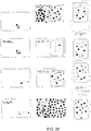
- FIG. 8 is an illustration of international character samples.
- Prior art gesture recognition systems utilize feature-based recognition approaches. These approaches require complex local character feature definitions if user interfaces are to be adapted to another foreign character set. Feature extraction for local character sets as shown in FIG. 8 can be an effort-consuming process. Even after adoption to local character sets users with a different local background, like immigrants or guest workers, may not be able to enter characters in a recognizable format. The same applies to people with motoric impairments that have to write characters in a complete different style. For many applications, especially online applications, a fast localization is a key requirement and no user group must be excluded. Prior art recognition systems do not allow an interactive user-related feature definition.
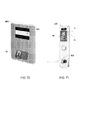
- FIG. 9 is a detailed view of a prior art secure contact-less reader with an authentication interface.
- a reader may be configured to receive an electronic identity card.
- authentication code information may have to be entered through a secure (but expensive) reader device as depicted in FIG. 9 . If a PC or Laptop is used to enter authentication information unauthorized access i.e. by key-loggers becomes feasible. Other attacks make use of the browser plug-in communicating with the Smartcard through the reader-DLL in order to get access to the PIN-code stored on the Smartcard.
- Prior art authentication cards are not able to connect during the entry of authentication information to a remote service. Especially for web-based applications it is a key requirement that a security token seamlessly integrates into the communication chain from the web application to the token and vice versa.
- FIG. 10 is an illustration of the prior art available interface area in communication mode.
- Disclosed token cards are mainly banking cards (see FIG. 5 and FIG. 7 ) based on IS07816 contact based interfaces.
- the user interfaces of the known token cards are conflicting with other component placements. If a contact-based card is attached to a contact reader, a big portion of the card disappears in the reader (shaded overlay area in FIG. 10 ), leaving a very small surface area for any form of interactivity.
- banking cards do not support any interactive mode while attached to a reader. In view thereof online authentication is not feasible.
- buttons typically have a user interface with extremely tiny buttons (see FIG. 7 and FIG. 10 ).
- the button size is restricted such that buttons must not interfere with the antenna, a potential embossing area and a potential magnet stripe.
- Document owners with visual or motoric impairments are unable to operate the device. Especially elder persons have difficulties with this sort of interface. The exclusion of such a large user group is not acceptable.
- FIG. 11 is an illustration of blocking areas for interactive sensors in prior art authentication cards.
- Prior art token cards have tight restrictions for input element placements. Button areas are normally kept separately from necessary card information areas. They must also not interfere with the cards corporate ID elements. As a consequence, the resulting button areas are extremely small.
- the illustration in FIG. 11 indicates blocking areas 61-65 of battery-powered token cards. The following components define the key area restrictions: battery 62, contact mode interface (ISO7816) 61, display module 63 and Corporate Identity elements 64-65.
- Prior art security tokens are relatively costly due over-specification, especially in the display interface. Furthermore, none of these security tokens comply with basic authentication requirements, such as a lifetime of at least 10 years, an interactive mode, NFC compatibility and on-card matching functionality.
- an embodiment of the security token comprises a tactile sensing user interface being arranged to receive a user-encoded secret, a decoding unit being arranged to generate a decoded secret by decoding the user-encoded secret, a comparison unit being arranged to compare the decoded secret with a copy of the secret stored in the token in order to verify the authenticity of a user.
- the security token provides on-card matching functionality.
- the tactile sensing user interface is arranged to capture tactile patterns and to provide a tactile pattern data stream which represents the user-encoded secret and which comprises a sequence of said tactile patterns to the decoding unit
- the decoding unit is arranged to generate the decoded secret by applying a private inverse transfer function to the tactile pattern data stream, and the private inverse transfer function is the inverse of a private transfer function applied by the user to encode the secret.
- the private inverse transfer function is definable by the user via the tactile sensing user interface in a configuration mode of the token.
- the private inverse transfer function further reflects user-specific tactile pattern deviations captured by the tactile sensing user interface in the configuration mode of the token, such that the entropy of the user-encoded secret is increased.
- the entropy of the user-encoded secret is further increased.
- the private inverse transfer function further reflects sensor-device-specific tactile pattern deviations applied by the tactile sensing user interface in the configuration mode of the token, such that the entropy of the user-encoded secret is increased.
- the entropy of the user-encoded secret is further increased.
- the token further comprises a release foil with printed tactile key information for defining the private inverse transfer function.
- a release foil with printed tactile key information for defining the private inverse transfer function.
- the tactile sensing user interface comprises an array of proximity sensors or mechanical pressure sensors.
- Proximity sensors and mechanical pressure sensors can be implemented relatively easy in a token of the kind set forth.
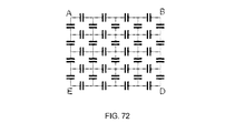
- the tactile sensing user interface comprises a mesh network of proximity sensing capacitors. Thereby, the number of I/O lines of the tactile sensing user interface is reduced.
- the proximity sensors comprise proximity sensing capacitors.
- Proximity sensing capacitors are particularly suitable for integration in a token of the kind set forth.
- the token further comprises a compressible layer on which the array of proximity sensing capacitors is mounted and counter-electrodes underneath the compressible layer, said counter-electrodes forming pressure-dependent capacitances in conjunction with the proximity sensing capacitors.
- the token further comprises button functions assigned to sub-areas of an area covered by the array of proximity sensors or mechanical pressure sensors, and the token further comprises a surface print design which provides a visual overview of said button functions.
- the user-encoded secret comprises a personal identification number and the private inverse transfer function translates elements of a user-defined character repertoire to digits of the personal identification number
- the user-defined character repertoire comprises at least one of the group of: alphanumeric character tactile patterns corresponding to said digits, key position tactile patterns corresponding to said digits, graphical symbol tactile patterns corresponding to said digits.
- Personal identification numbers are widely used to authenticate users.
- the user-encoded secret comprises a signature short-cut and the private inverse transfer function decodes a tactile pattern which represents said signature short-cut.
- the token further comprises at least one of the group of: a feedback indicator, a status indicator, a display, an audio output.
- the feedback indicator, status indicator and display may provide visual feedback to the user.
- the audio output may provide audible output to the user which is useful if the user is visually impaired, for example.
- the token further comprises a display, the display comprising at least one of the group of: icons, segments, active areas that have been structured by a printed shadow mask.
- iconized displays are relatively cheap and power-efficient.
- the token further comprises a backchannel implemented by a program element, such as a Java-applet, for communicating with a host system such that the token may use a display of the host system as a virtual display.
- a program element such as a Java-applet
- the token is arranged to receive power for operating the tactile sensing user interface, the decoding unit and the comparison unit from an external electromagnetic field.
- the token further comprises a radio frequency identification (RFID) interface being arranged to enable communication with RAID devices and NFC-enabled devices and being arranged to receive power from an electromagnetic field generated by said RAID devices and NFC-enabled devices.
- RFID radio frequency identification
- the token has an increased range of use.
- the token may act as a security extension for an NFC-enabled Smartphone.
- the token further comprises a power unit being arranged to power the token from an external electromagnetic field, and the power unit comprises one or more super capacitors for buffering energy, said super capacitors consisting of electrochemical double-layer capacitors with an energy density substantially greater than the energy density of conventional electrolytic capacitors, in particular hundreds of times greater than the energy density of conventional electrolytic capacitors.
- the power unit may buffer energy for performing relatively complex functions.
- the token further comprises a tapped antenna structure or an antenna with at most three turns in order to maximize the efficiency of power coupling to the token.
- the token further comprises an optical communication interface which is arranged to establish a secure backchannel, said optical communication interface being embedded into the body of the token.
- encrypted private information may be transmitted securely.
- the surface of the token is overlaid by the tactile sensing user interface such that tactile patterns entered by a user are sensed through said surface.
- the token may be manufactured at high volumes with a relatively low cost.
- the tactile sensing user interface comprises a key-pad layout.
- a key-pad layout is useful for interactive access cards.
- the token is an electronic identification card or an electronic passport.
- the token according to the invention is particularly suitable as an electronic identification card or an electronic passport since the on-card matching functionality enables a very secure authentication process.
- the token has a portrait form factor. Thereby, a relatively large tactile sensing area may be offered.
- an authentication system which comprises an authentication server and a security token of the kind set forth, wherein the security token is further arranged to send a verification result to the authentication server.
- an authentication system comprising an authentication server and a security token
- the security token comprises a tactile sensing user interface being arranged to receive a user-encoded secret; a decoding unit being arranged to generate a decoded secret by decoding the user-encoded secret; an encryption unit being arranged to encrypt the decoded secret in order to generate an encrypted decoded secret; wherein the security token is further arranged to send the encrypted decoded secret to the authentication server; wherein the authentication server comprises: a decryption unit being arranged to decrypt the encrypted decoded secret; a comparison unit being arranged to compare the decoded secret with a copy of the secret stored in the authentication server in order to verify the authenticity of a user. Thereby, a copy of the secret need not be stored in the security token which may offer additional security.
- said authentication system forms part of at least one of the group of: a governmental service, a web shop service, an online auction service, an online gaming service, an online banking service, an online media service, an online airline service, a car access system, a door lock system, an in-flight payment service, a flight attendant panel, a mobile phone based identification system, a mobile phone based payment system, a software license control system.
- UI embedded tactile sensing user interface
- a tactile sensing interface like an array of proximity sensing capacitors may be used to detect tactile patterns and provide a tactile pattern data stream to the electronic device.
- the electronic device may reassemble a secret from the sensed tactile pattern data.
- said secret is transferred by the user into the extremely large code space of all known tactile patterns by applying a private (secret) transfer function. Reassembling the secret from entered tactile patterns requires application of an inverse transfer function.
- FIG. 12 is a detailed front view of a security token 10 in accordance with an embodiment of the invention.
- a token 10 which uses the techniques for tactile pattern association according to the invention.
- the implementation of the tactile pattern association will be described below with reference to the illustrated electronic device 10, which may be an electronic identification card, an electronic online payment card, an electronic banking card, an electronic credit card, an electronic access card, an electronic passport, an electronic drivers license, an electronic money card, an electronic health card, an electronic loyalty card, an electronic door entrance card or any combination thereof.
- the techniques described herein are usable with any contact-less Smartcard device configured to receive input through a tactile sensing interface.
- the electronic device 10 may be a security token powered by an electromagnetic field and incorporating the functionality of one or more Smartcard devices, such as an electronic identification card, an electronic online payment card, an electronic banking card, and so forth.
- Smartcard devices such as an electronic identification card, an electronic online payment card, an electronic banking card, and so forth.
- a user may authorize governmental services, authorize online transactions, authorize cash out payments, authorize access to locations, authorize access to a machine, authorize access to a device, and authorize access to a vehicle.
- the electronic device 10 also may communicate with other devices using short-range connections, such as contact-less communication according to ISO14443 or near field communication (NFC).
- short-range connections such as contact-less communication according to ISO14443 or near field communication (NFC).
- the electronic device 10 may be a model of a German Identification Card as illustrated by FIG. 50 , available from Farbbucherei, Berlin.
- the token 10 includes a body 12 that embeds and protects the interior components from physical damage.
- the body 12 may be formed from any suitable material such as plastic, card board, paper, or a composite material and may allow certain frequencies of electromagnetic radiation to pass through to the contact-less communication circuitry within the token 10 to facilitate contact-less communication or to pass through to the optical communication circuitry within the token 10 to facilitate optical communication.
- FIG. 13 is a first simplified block diagram of the device of FIG. 12 in accordance with an embodiment of the invention. Additional details of the illustrative token 10 will be explained with reference to FIG. 13 , which is a block diagram illustrating various components and features of the token 10 in accordance with an embodiment of the present invention.
- the block diagram includes the display 24 and the status indicator 25 and the output structures 59 and the RFID interface 44 discussed above, as well as many other components.
- the operation of the token 10 may be controlled by a first central processing unit (CPU) 46 that provides the processing capability required to execute a task scheduler, a JAVA virtual machine, programs, and any other functions of the token 10.
- the first CPU 46 may include a single processor or it may include a plurality of processors.
- the first CPU 46 may include "general purpose" microprocessors, a combination of general and special purpose microprocessors, instruction set processors, and/or related chips sets, and/or special purpose microprocessors.
- the first CPU 46 also may include on-board memory for caching purposes.
- the long-term storage 48 of token 10 may be used for storing data required for the operation of the first CPU 46 as well as other data required by the token 10.
- the storage 48 may store a first firmware for the token 10 that is used by the first CPU 46.
- the first firmware may include a task scheduler, as well as other programs that enable various functions of the token 10, UI functions, and/or processor functions.
- the storage 48 also may store components, such as secrets, reference tactile pattern data, and decision trees.
- the long term storage 48 may store data files such as media (for example audio speech samples), cryptographic keys and signatures, and any other suitable data.
- the long term storage 48 may be a non-volatile memory such as read-only memory, flash memory, or any other suitable optical, magnetic, or solid-state computer readable media, as well as a combination thereof.
- the input structures 60 are configured to receive input from a user's or object's tactile pattern and to send the information to the second CPU 56, which interprets the tactile pattern and performs a corresponding action.
- the input structures 60 may employ any suitable type of tactile pattern sensor technology such as resistive, capacitive, infrared, surface acoustic wave, electromagnetic, or near field imaging.
- the input structures 60 may be configured to sense mechanical pressure applied to the surface of a sensor.
- the second CPU 56 may provide the infrastructure for exchanging data between the first CPU 46 and input/output devices, such as the input structures 60 and the display 24.
- the second CPU 56 may contain one or more integrated circuits and may be integrated with the CPU 46 or exist as a separate component.
- the second CPU 56 also may provide the infrastructure for communicating with external devices through the I/O ports 58.
- the I/O ports 58 may include I/O ports for connecting the CPU 56 to an external computer, I/O ports implementing a JTAG debugging interface, an ISO7816 compatible serial interface, an I2C-bus interface, or the like.
- the long-term storage 49 of token 10 may be used for storing data required for the operation of the second CPU 56 as well as other data required by the token 10.
- the storage 49 may store a second firmware for the token 10 that is used by the second CPU 56.
- the firmware may include a task scheduler, as well as other programs that enable various functions of the token 10, UI functions, and/or processor functions.
- the storage 49 also may store components, such as reference tactile pattern data, and decision trees.
- the long term storage 49 may store data files such as media (e.g., audio speech samples), and any other suitable data.
- the long term storage 49 may be a non-volatile memory such as read-only memory, flash memory, or any other suitable optical, magnetic, or solid-state computer readable media, as well as a combination thereof.
- the first CPU 46 may control the operation of the token 10 and the second CPU 56 may comprise the decoding unit for generating the decoded secret.
- the first CPU 46 may compare the decoded secret with the copy of the secret stored in the token.
- FIG. 14 is a second simplified block diagram of the device of FIG. 12 in accordance with an embodiment of the invention.
- FIG. 14 illustrates another embodiment of token 10.
- the difference with the embodiment described with reference to FIG. 13 is the RFID interface being connected to the second CPU 56 instead of the first CPU 46.
- the benefit of this implementation is compatibility with less expensive security controllers.
- a user may enter tactile patterns using the input structures 60 located on external surfaces of the token 10.
- the user input structures 60 may include the input structures 14, 15, 16 shown in FIG. 1 and may communicate with the first CPU 46 through the second CPU 56.
- the token 10 may include an integrated power unit 64 for powering the token 10 by an external electromagnetic field without the need for an embedded battery.
- the power unit 64 may include one or more super capacitors for the purpose of energy buffering.
- MCU ultra-low-power microcontroller units
- Multifunctional Smartcards have far higher power requirements than single chip cards. Higher power translates into higher load (less impedance) of the antenna circuit. As a consequence, the quality factor of the resonator circuit reduces so much that the coupling between the reader's loop antenna and the Smartcard's loop antenna acts as a transformer coupling. From that perspective, a completely different coupling approach is required for multifunctional Smartcards.
- Power matching requires the source impedance and the load impedance to be conjugate complex.
- a load transformation is implemented by attaching the load impedance to a tap of the Smartcard's antenna. As a consequence, the load is transformed by the square of the ratio between the tap turns to the total amount of turns. Beside load transformation the tapped antenna also provides voltage transformation, resulting in a lower voltage u ectified This is desirable because modem chip fabrication processes have far lower supply voltage limits than older processes. Power matching is implemented for the operational point of the Smartcard's maximum specified supply current.
- FIG. 16 is a schematic of a contact-less power supply involving load transformation and an additional supply path for organic electronics.
- FIG. 16 illustrates a rectifier configuration that may provide a high voltage to organic electronics like OLED displays.
- the logic supply U rectified may be generated from a tap with 2-3 turns for best power matching.
- the tuning capacitor C 2 may be connected to the top of L 2 .
- the OLED supply may provide up to 6V.
- the token 10 allows access to user input structures 14, 15, 16 through which a user may interface with the device.
- Each user input structure 14, 15, 16 may be configured to sense tactile patterns when actuated.
- the input structure 14 may include an area for sensing tactile patterns which, when entering a tactile pattern, causes the tactile pattern to be captured and to be associated with reference tactile patterns with the purpose of decoding said tactile patterns and providing the associated tactile patterns to the token 10 for further processing.
- the input structure 15 may include a key, that when touched, causes a related digit to be entered into the token for further processing by the token 10.
- the input structure 16 may include a button that, when touched, causes a user interface function to be executed, which function may comprise deleting the last associated tactile pattern or cancelling the entry of a secret using tactile patterns.
- the token 10 may include any number of user input structures existing in various forms including buttons, keys, switches, sliders, input pads, or other suitable forms.
- An important aspect of the invention is to install a private inverse transfer function on a contact-less powered Smartcard that may act as decoding function for tactile patterns that have been utilized by a user to transfer or encode a secret into a user-encoded secret.
- a tactile pattern sensing interface may be embedded and the installed private inverse transfer function may be utilized for decoding sensed tactile patterns.
- Tactile pattern decoding as disclosed here implements an approach that differs from normal online handwriting recognition ("OHR").
- OHR recognition systems target at a best possible recognition despite all user-dependent differences in tactile pattern generation. If all user-related differences in generating the tactile patterns are excluded from tactile pattern recognition and only the user-independent characteristics are utilized for pattern recognition a huge entropy reduction of the involved code space of tactile patterns will occur.
- the main objective of an authentication system is the identification of a user. A best possible identification requires all available user-related information being considered during authentication. From that perspective it is irrelevant whether thirds can recognize a tactile pattern of a user. In order to maintain the entropy of a tactile pattern it must not be translated into any intermediate meaning that thirds may understand. For that reason the approach disclosed here is based on the fact that only the user is able to assign a unique meaning to every of his tactile patterns. The objective of the invention is not to recognize a tactile pattern but to associate a tactile pattern by assigning a new member of a different character repertoire to a tactile pattern. Recognizing would imply that the tactile pattern is converted into an understandable intermediated format which is not desired in case of authentication systems.
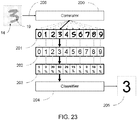
- FIG. 17 is an illustration of a secret verification approach based on tactile patterns.
- An issuing authority 221 generates a secret x 223 utilizing code repertoire N 240. It sends 230 a copy of the secret 222 to the user 220. Another copy 224 of the same secret x is installed on token 10.
- the user 220 By entering his representation of the secret 222 the user 220 defines 231 a private transfer function F 234 that he applies to the copy of the secret x 222, thereby effectively encoding the secret, resulting in a user-encoded secret y 206, which is the tactile pattern entered into the tactile sensor 14.
- the user-encoded secret y 206 is constructed from the character repertoire T 241 of all tactile patterns.
- the private transfer function F 234 is only known to the user 220.
- the user 220 may install 232 a private inverse transfer function F -1 235 on the token 10.
- the token 10 may apply the inverse transfer F -1 23 5 to that user-encoded secret y 206 resulting in a decoded secret x' 207 that utilizes the same character repertoire as the secret x 223.
- Defining a private inverse transfer function F -1 235 is very useful if the user wants to implement a code conversion from digits to alphanumeric characters, for example, or wants to add an additional character set.
- the verifier 208 also referred to as comparison unit 208, verifies the decoded secret x' 207 against the copy of the secret x 224 installed on the token 10 and communicates the verification result to a receiver 209.
- the issuing authority 221 has no knowledge of the private transfer function 234 and the private inverse transfer function 235.
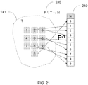
- FIG. 18 is an illustration of a private transfer function used to encode a secret by using tactile patterns. Illustrated by FIG. 18 is a limited character repertoire N 240 that may be used to encode the copy of the secret x 222.
- character repertoire N 240 may represent the natural numbers from 0 to 9 which is the case with PIN entries, and the character repertoire T 241 may represent tactile patterns such as written characters, icons, signature short-cuts, and many more in all writing styles.
- a four-digit secret x 222 may be transferred by function F 234 into a user-encoded secret y 206 represented by a sequence of four tactile patterns.
- the private inverse transfer function F -1 235 should be unambiguous for at least the elements of the character repertoire T 241 that are used to encode the secret x 222; otherwise it will be impossible to associate the user-encoded secret y 206. In case of a large group of users, which is typical for authentication applications, the code space created by character repertoire T 241 is huge.
- the private inverse transfer function according to the invention may be configured to utilize the variance between tactile patterns of the same meaning to minimize user-specific spread between the same tactile patterns.
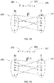
- FIG. 19 is an illustration of an inverse transfer function used to associate a secret represented by tactile patterns.
- FIG. 19 further illustrates decoding of the user-encoded secret y 206 that may be achieved by applying the private inverse transfer function F -1 235.
- a natural spread in generating the tactile pattern, i.e. the user-encoded secret y 206, will result in a spread of the secret x' 207 when the private inverse transfer function F -1 235 is applied.
- the private inverse transfer function F -1 235 is implemented by a set of private reference tactile patterns provided by the user 220.
- Decoding the user-encoded secret y 206 can be achieved by correlating the user-encoded secret y 206 with every member of the character repertoire T 241.
- the correlation results may be evaluated by a classifier that may consider the variance between the same tactile patterns.
- the variance between the same tactile patterns may compensate spread of the decoded secret x' 207.
- Both the private transfer function F 234 and the private inverse transfer function F -1 235 are only known to the user. This knowledge is difficult to capture by unauthorized persons. Therefore, additional security is provided for the entry of a secret.
- the ability to define an arbitrary private inverse transfer function F -1 23 5 may enable a user to translate the copy of the secret x 222 into any combination of tactile patterns, which enables easy localization of the secret 222 by applying tactile patterns representing any local or foreign characters that are elements of the character repertoire T 241.
- a tactile pattern decoder for Chinese numbers and ten key-pad positions may be defined, which enables decoders that may support multilingual applications.
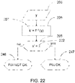
- the correlation result 203 may be evaluated by the classifier 204.
- the classifier may select the most probable candidate from the group of tactile reference data streams 201 and may assign the member from the code conversion table 202 that is associated to said most probable candidate. If, for example, the user enters the four digits "1234" by drawing them sequentially on the token's sensing device 14 - wherein each of the drawn digits represents one sensed tactile pattern 19 - then the token 10 may associate as described above each sensed tactile pattern data stream 206 with each of the ten reference tactile pattern data streams 201 stored in the token and determine the probability of coincidence 203.
- the classifier 204 may evaluate for each sensed tactile pattern stream 206 the most probable candidate form the group of reference tactile data streams 201. The classifier 204 may then assign for each of the most probable reference tactile data streams a member from the code conversion table 202 that is associated to said most probable candidate. As a result the classifier may have associated the digits "1", "2", "3" and "4" in that order to the sequence of the four sensed tactile data streams 206, that may have resulted in this example as a sequence of digits 205 that reassemble the secret "1234".
- optical or acoustical feedback may be provided to the user.
- the reassembled secret may be verified against a stored copy of the secret. The verification result may be communicated to another device in encrypted format for the purpose of authenticating the user.
- tactile patterns which are "associated”.
- associated means that elements of the code space of the secret (such as digits of a PIN) have successfully been associated (by the decoding unit) with corresponding elements of the code space of tactile patterns.
- the approach disclosed here utilizes the same tactile pattern sensor 14 and the same signal conditioner 260 for the definition of the private inverse transfer function (configuration mode) and for the authentication function (authentication mode).
- configuration mode definition of the private inverse transfer function
- authentication mode authentication mode
- a fully differential decoding system is implemented.
- this fully differential decoding system is able to cancel out most non-linearity introduced by the tactile sensor 14 as well as by the conditioner 260 yielding a decoding system that better copes with manufacturing spread.
- the differential approach is especially useful for cancelling off effects caused by non-linear processing functions in conditioner 260. Canceling the device-specific variation of the tactile sensor 14 corresponds to decoding a signal that had been encoded by a physical unclonable function.
- This physical unclonable function caused by the device-specific sensor variation introduced during token manufacturing contributes to the private transfer in the configuration mode.
- the device-specific sensor variation inversely contributes to the private inverse transfer function, resulting in a decoding of the physical unclonable function applied by the sensor device variation in the configuration mode.
- a private inverse transfer function that is installed on one token device may not work on another token device.
- the device- specific sensor variations further increase the code entropy of the encoded secret 206 due to the differential approach.
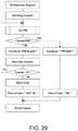
- the "Authenticate"-routine 415 sends a "Get PIN” request 416 to the second CPU 56 that is responsible for the I/O subsystem.
- the "Get PIN” request 416 which is further detailed by FIG. 30 , invokes the tactile pattern decoder as described above.
- the "Authenticate"-routine 415 verifies the authentication information by comparing it against a stored copy.
- the "Authenticate”-routine involves a retry count mechanism that stops the authentication after a limit of wrong authentications has been reached. If the authentication is successful the verification result is transferred in a response APDU 410 through the PC/SC-layer 405 back to the JAVA applet 403. The JAVA applet returns the response through the browser 401 back to the shopping portal 400. Example applications using this approach are described further down in more detail.
- a release foil indicating the key pad positions may be attached to the card when it is delivered to the user.
- the foil may also include a tactile marking pattern to support visually impaired users.
- the pre-installed tactile patterns may be replaced by the trained reference tactile pattern set.
- Reference tactile patterns may be defined by the document manufacturer (position codes representing buttons) or by the document owner, i.e. the user (personal handwriting). The document manufacturer may also apply restrictions related to the size of character repertoires and blocking areas.
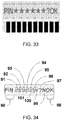
- FIG. 33 is a detailed view of an electrochromic icon display according to an embodiment of the invention.
- FIG. 34 is a detailed view of an electrochromic combinational display providing icons for fixed content and segmented digits for variable number display according to an embodiment of the invention.
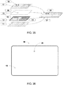
- FIG. 35 is an illustration of display integration by printing according to an embodiment of the invention.
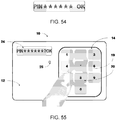
- the token 10 may also include a display 24 which may display various characters or icons under control of the device.
- the display 24 may show a text string "PIN ?" to request the entry of a personal identification number (PIN), a text string "PIN OK" to feedback the successful entry of a digit sequence, among others.
- the display 24 also may display other text strings or icons 31 that provide feedback to a user, such as successful tactile pattern decoding, unsuccessful tactile pattern decoding, successful decoding of a sequence of tactile patterns, and the like.
- the display 24 may be any type of display such as a liquid crystal display (LCD), a light emitting diode (LED) display, an organic light emitting diode (OLED) display, an electrophoretic (ePaper) display, an electrochromic (EC) display, or any other suitable display.
- the display 24 may comprise icons, segments, or active areas that are later structured by a printed shadow mask.
- the display 24 may be used to display information that allows a user to interact with the device.
- the content of display 24 may include characters and/or icons 33 that guide the entry of a secret into token 10.
- the display content is quite limited as it is restricted to status information rather than displaying secret code information. Instead, secret information is masked. According to the invention the display content is limited such that it can be displayed with a minimum amount of icons.
- the invention utilizes an electrochromic display and in a further embodiment an OLED display.
- the electrochromic display is short-term bi-stable.
- the display content is fading out over time.
- FIG. 34 illustrates a display type that offers both of the two worlds: crystal sharp icons 90 and 98-101 combined with variable 7-segment digits 91-96. This display can be used for authentication as well as for displaying currency values for e.g. a money card application.
- the icons 90 and 97-101 are logically combined as one display unit as the digits are, resulting in seven display units with six times seven and one time six segments. This construction is controlled by a 7x7 matrix structure that requires 14 control lines.
- Electrophoretic and LCD displays require special attention with respect to the supply voltage. In case of electrophoretic displays voltages well above 7V are required for a display update. The bi-stability of the electrophoretic displays is a drawback in authentication applications. From that perspective the invention disclosed here utilizes a printed electrochromic display having an operational voltage of 2.5V. In another embodiment, an OLED-display with a printed shadow mask is used and in a further embodiment a structured OLED-display is used.
- the invention proposes to print a display, preferably an electrochromic or an OLED display, directly onto a substrate material used for the card construction.
- This approach results in a homogeneous card construction which is of key importance for governmental documents. Furthermore, no display pre-manufacturing step is required and the extra cost for the display substrate is avoided, which is the main cost contributor to the pre-manufactured display besides equipment depreciation.
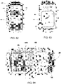
- FIG. 35 Assembly according to the invention is illustrated in FIG. 35 .
- the token body is fabricated from the four substrate layers 11, 12, 15 and 17.
- the display 14 is directly printed to the substrate 12 comprising the antenna 13.
- a transparent compensation layer 15 comprising an exemplary cut-out 16 that compensates the topology chips attached to layer 13 is assembled on top of layer 12.
- a transparent layer 17 comprising an unprinted window area 18 is assembled on top of layer 15.
- the assembled layers are laminated applying temperature and pressure for a defined time, resulting in the token body 21 with the visible display beneath window 19.
- the token 10 may also include a status indicator 25 which may display blink codes under control of the device.
- the status indicator 25 may indicate a constant signal if a tactile pattern is being entered, a single short blink if a tactile pattern is associated, a triple short blink if a tactile pattern has not been associated, a long blink if a the required amount of tactile patterns has been successfully associated.
- the status indicator 24 may be any type of display element such as a liquid crystal element (LCD), a light emitting diode (LED) element, an organic light emitting diode (OLED) element, an electrophoretic (ePaper) element, an electrochromic (EC) element, or other suitable display elements.
- the status indicator 25 may be used to display information that allows a user to interact with the device, especially in the absence of a display 24.
- the information provided by the display indicator 25 may include various optical signals that are indicated under control of the token 10.
- the content of the status indicator 25 may include intensity modulated signals that guide the entry of a secret into token 10.
- the electronic device or token 10 may also include various input and output (I/O) ports for implementation of communication lines like IS014443, ISO7816, optical communication and the like.
- I/O input and output
- a JTAG interface and an ISO7816 contact interface may be provided.
- the token 10 may also include an audio output structure 59.
- the audio output structure 59 may include one or more sound transducers for outputting audio data.
- the output structure 59 may indicate a constant tone if a tactile pattern is being entered, a single short beep if a tactile pattern is associated, a triple short beep if a tactile pattern has not been associated, a long beep if a required amount of tactile patterns has been successfully associated, a speech sample generated from a text string.
- the audio output structure 59 may be used to output sound information that allows a user to interact with the device, especially in absence of a display 24 and/or in absence of a status indicator 25.
- the information provided by the output structure 59 may include various audio signals that are indicated under control of token 10.
- the audio output structure 59 may include intensity modulated tone signals and speech messages generated under control of token 10 that guide the entry of a secret into token 10.
- the token 10 may further include a radio frequency identification (RFID) communication interface 44.
- RFID radio frequency identification
- the RFID interface 44 may allow for close range communication with RFID devices or with NFC-enabled devices at standard data rates (up to 848 kb/s) and may comply with standards such as ISO1443, ISO 18092 or ISO 21481. In certain embodiments, the communication may occur within a range of approximately 0.5 to 2 cm.
- the close range communication with the ISO14443 interface 44 may take place via magnetic field induction, allowing the RFID interface 44 to communicate with RFID interfaces or with NFC interfaces.
- FIG. 36 is a detailed backside view of a token comprising optical backchannel communication.
- an optical communication link may be embedded into the token's body 12 at the token's 10 rear side, for example.
- the optical element 25 may be implemented as an active or reflective optical element 25 that may interface with an optical receiver embedded into another communication device such as a contact-less Smartcard reader.
- the optical element 25 may be implemented using technologies such as a liquid crystal element (LCD), a light emitting diode (LED) element, an organic light emitting diode (OLED) element, an electrophoretic (ePaper) element, an electrochromic (EC) element, or other suitable display elements.
- the backchannel enables the transmission of encrypted private information that must not be intercepted by thirds with the purpose of information decoding by any means.
- more than 50% of the cards surface area is provided for tactile pattern entry.
- the entry area is enlarged in one embodiment by using a portrait-style card format instead of the classical landscape-style.
- Untrained tokens may have a preconfigured training set installed that installs a key pad.
- the card may have a release foil attached which contains tactile key information. After training the release foil can be removed and the tactile sensing area is sufficient for entry by visually impaired users.
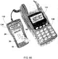
- an ID1-sized token together with the Smartphone can be easily held by one hand while the other hand is used to enter tactile authentication information.
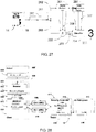
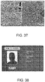
- FIG. 37 is a detailed view of an electronic document inlay comprising a tactile sensing interface.
- the invention enables the generation of many configurations, such as the above-described configurations, from a single unified hardware design. Instead of positioning single-touch buttons the inlay as illustrated by FIG. 37 the token surface is overlaid by a two-dimensional sensor that senses tactile patterns entered through the cards surface.
- the tactile sensor is made of an array of capacitors that are affected by tactile patterns above them.
- a center-of-mass (or center-of-gravity) algorithm is applied to calculate a position from the activity-levels of all sensor capacitors.
- the layer underneath the sensing capacitors is made compressible.
- a counter-electrode underneath each of the sensing capacitors forms together with the electrodes of the sensing capacitors another capacitor in vertical direction that depends on the distance between the sensing capacitor and the counter plate. The distance depends on mechanical pressure applied to the sensor surface, resulting in a pressure-dependent capacitor.
- the pressure sensor is required to add pressure information to the writer-dependent characteristics.
- buttons and button diameter are used to define button areas to which functions are allocated. The same approach is used to define even more advanced interaction functions.
- button positions and functions are defined they can be supported by the surface print design.
- the surface print is normally applied to the inside of the card's top layers.
- the shadow mask 14 is applied to structure arbitrary characters.
- the shadow mask color may be black in case of active displays (OLED) in order to avoid light feed-through.
- OLED active displays
- An important benefit of the shadow mask approach results from the low requirements for display manufacturing. Resolution requirements are low resulting in extremely low clean room requirements. Standard label printing equipment can be used for display manufacturing.
- a printed electrochromic display is used that is redesigned according to the application requirements. If the electrochromic display is not directly printed onto a document's substrate the display has to be replaced as a component for different configurations. The hardware design of the inlay remains unchanged; only the display components are replaced by another version.
- the token disclosed here has a minimum of placement requirements.
- the tactile pattern sensing area can completely overlay information areas of a document. Entering tactile patterns is intuitive and self-explanatory and does not require any further printing. Even an indication of the sensing area by highlighting or shading may not be required if the document structure implies a certain area for entry, as is the case with the German electronic ID-card.
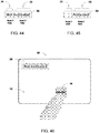
- FIG. 44 illustrates that the display comprises the icons "Not” 71 and "Activated” 72.
- the sensing area representing slider 14 may be actuated by the user's finger by e.g. making a left to right to left slide, a corresponding tactile pattern representing the slide may be associated and the token 10 may be enabled to execute an application program on the first CPU 46 and may communicate via the RFID interface 44 and, as illustrated by FIG. 45 , the icon "Not” 71 may be turned off.
- FIG. 44 and FIG. 45 can be implemented by a printed electrochromic display or a printed OLED display.
- FIG. 47 illustrates another embodiment of the token 10 comprising a two-dimensional tactile sensing interface 14, an icon display 24 and a status indicator 25.
- This embodiment may be used to enter a secret being, for example, a PIN code or a password comprising four characters.
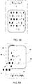
- FIG. 48 illustrates the layout of display 24.
- the display icon set may comprise the icon "PIN", four star icons 81, 82, 83, 84, a "?” icon 85 and an "OK” icon 86.
- the messages displayed while entering the four character secret are illustrated by FIG. 49 .
- the corresponding control signals for the icons are depicted by truth table 99.
- token 10 may be brought into close contact with an RFID interface in order to supply the token 10 with power. Power availability may be signaled by display 24 by displaying, for example, the message "PIN ?". This message may also indicate the request to start the entry of a tactile pattern sequence that represents the secret to be entered. As soon as the tactile sensor senses activity the status indicator 25 may be turned on. As an example, a first character may have been successfully associated. The token 10 may then respond by displaying message 92. A star icon without a question mark may mean that a character has been successfully associated. As an example, the second tactile pattern may not have been successfully associated by the token 10. As a consequence, message 93 may indicate a question mark icon 85, indicating that an error occurred.
- Token 10 may display message 94 in case a third tactile pattern has been successfully associated.
- Token 10 may display message 95 in case a fourth tactile pattern has been successfully associated.
- the device may now have captured and successfully associated all four tactile patterns and may have verified the entered secret against a representation of the same secret stored in token 10.
- Message 95 also indicates a successful authentication.
- message 96 may be displayed. In this case, the authentication process may start again and message 91 may be displayed.
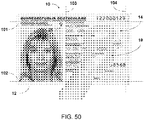
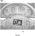
- FIG. 50 is a detailed front view in accordance with another embodiment wherein the secret comprises a personal identification number that comprises a sequence of numerical tactile patterns and wherein the tactile sensing interface is integrated into an electronic ID card and wherein status information guiding the user entry process is indicated by an optical element embedded into the document body.
- This exemplary embodiment of the token 10 comprises a two-dimensional tactile sensing interface 14 and a status indicator 25.
- a web application may interface with the token 10 through a browser running a client-side JAVA applet that may send a command APDU via the JAVA Smartcard I/O Application Programming Interface (API) through the PC/SC-interface to the token 10 and thereby request authentication.
- the token 10 captures the authentication information 19 which in this case may be any combination of tactile patterns, verifies the authentication information against a secret that may be a six digit PIN stored on the token 10 and returns the verification result by a response APDU to the JAVA script, which may forward the information to the web application running on a host system.
- This embodiment may be used to enter a secret that as an example may be a six-digit PIN code or a six-character password as required by the illustrated German electronic ID card.
- the tactile pattern entry area 14 may according to this exemplary embodiment be positioned to comply with graphical and textual boundaries of the electronic ID card.
- the two-dimensional tactile sensor does not interfere with any of the optical security features embedded in the documents surface and hence does not require a redesign of the security feature resulting in seamless document integration. Thus, it is possible to integrate a on-card matching functionality into existing documents.
- the horizontal boundary 102 may comply with the lower boundary of the card holder image
- the horizontal boundary 101 may comply with the upper boundary of the document identifier "Personalausweis”
- the vertical boundary 103 may comply with the horizontal start position of the card holder name
- the vertical boundary 104 may comply with the horizontal right boundary of the document number.
- An application area of this embodiment may be the activation of time-shared software licenses wherein the software licenses are centrally allocated to a user who authenticates towards a computer using the token 10 in order to gain access to production software.
- the token 10 is removed from the RFID interface the duration of the software utilization is centrally captured.
- a company card can be used to enable time-shared software. This enables new business models based on a company card.
- Software licenses may be allocated by a central service. If a user logs in and authenticates by means of the company card, the related software licenses will become available.
- any reference sign placed between parentheses shall not be construed as limiting the claim.
- the word “comprise(s)” or “comprising” does not exclude the presence of elements or steps other than those listed in a claim.
- the word “a” or “an” preceding an element does not exclude the presence of a plurality of such elements.
- the invention may be implemented by means of hardware comprising several distinct elements and/or by means of a suitably programmed processor. In a device claim enumerating several means, several of these means may be embodied by one and the same item of hardware.
- the mere fact that certain measures are recited in mutually different dependent claims does not indicate that a combination of these measures cannot be used to advantage.
Landscapes
- Engineering & Computer Science (AREA)
- Theoretical Computer Science (AREA)
- Physics & Mathematics (AREA)
- General Physics & Mathematics (AREA)
- Business, Economics & Management (AREA)
- Computer Security & Cryptography (AREA)
- Computer Hardware Design (AREA)
- General Engineering & Computer Science (AREA)
- Accounting & Taxation (AREA)
- Software Systems (AREA)
- Strategic Management (AREA)
- General Business, Economics & Management (AREA)
- Computer Networks & Wireless Communication (AREA)
- Microelectronics & Electronic Packaging (AREA)
- Finance (AREA)
- Human Computer Interaction (AREA)
- Mathematical Physics (AREA)
- User Interface Of Digital Computer (AREA)
Priority Applications (3)
| Application Number | Priority Date | Filing Date | Title |
|---|---|---|---|
| EP12155351A EP2575084A1 (de) | 2011-09-30 | 2012-02-14 | Sicherheitstoken und Authentifizierungssystem |
| US13/627,581 US9898695B2 (en) | 2011-09-30 | 2012-09-26 | Security token and authentication system |
| CN201210364301.3A CN103036679B (zh) | 2011-09-30 | 2012-09-26 | 安全令牌和认证系统 |
Applications Claiming Priority (3)
| Application Number | Priority Date | Filing Date | Title |
|---|---|---|---|
| EP11183420 | 2011-09-30 | ||
| EP11188858 | 2011-11-11 | ||
| EP12155351A EP2575084A1 (de) | 2011-09-30 | 2012-02-14 | Sicherheitstoken und Authentifizierungssystem |
Publications (1)
| Publication Number | Publication Date |
|---|---|
| EP2575084A1 true EP2575084A1 (de) | 2013-04-03 |
Family
ID=45562258
Family Applications (1)
| Application Number | Title | Priority Date | Filing Date |
|---|---|---|---|
| EP12155351A Ceased EP2575084A1 (de) | 2011-09-30 | 2012-02-14 | Sicherheitstoken und Authentifizierungssystem |
Country Status (3)
| Country | Link |
|---|---|
| US (1) | US9898695B2 (de) |
| EP (1) | EP2575084A1 (de) |
| CN (1) | CN103036679B (de) |
Cited By (17)
| Publication number | Priority date | Publication date | Assignee | Title |
|---|---|---|---|---|
| EP2701107A1 (de) * | 2012-08-24 | 2014-02-26 | Samsung Electronics Co., Ltd | Vorrichtung und Verfahren zur Bereitstellung von Interaktionsinformationen mittels Verwendung eines Bildes auf Vorrichtungsanzeige |
| EP2819107A1 (de) | 2013-06-25 | 2014-12-31 | Nxp B.V. | Sicherheitstoken und Transaktionsermächtigungs-System |
| WO2014206505A1 (en) | 2013-06-26 | 2014-12-31 | Steinar Pedersen | Improvements in or relating to user authentication |
| EP2869230A1 (de) | 2013-10-29 | 2015-05-06 | Nxp B.V. | Verfahren zum Betreiben eines Sicherheitstokens, Computerprogrammprodukt und Sicherheitstoken |
| EP2930641A1 (de) | 2014-04-07 | 2015-10-14 | Nxp B.V. | Verfahren zur Programmierung einer Chipkarte, Computerprogrammprodukt und programmierbare Chipkarte |
| US9317675B2 (en) | 2013-03-19 | 2016-04-19 | Nxp B.V. | Smartcard, smartcard system and method for configuring a smartcard |
| US9342680B2 (en) | 2013-03-19 | 2016-05-17 | Nxp B.V. | Security token, data processing system and method of processing data |
| US9396593B2 (en) | 2013-03-19 | 2016-07-19 | Nxp B.V. | Security token, control system and control method |
| EP3109793A1 (de) | 2015-06-22 | 2016-12-28 | Nxp B.V. | System zum erkennen von fingerabdrücken |
| US9600647B2 (en) | 2013-11-18 | 2017-03-21 | Tata Consultancy Services Limited | Multi-factor authentication |
| WO2017102699A1 (de) * | 2015-12-15 | 2017-06-22 | Bundesdruckerei Gmbh | Id-token mit geschütztem mikrocontroller |
| DE102016203610A1 (de) * | 2016-03-04 | 2017-09-07 | Bundesdruckerei Gmbh | Wert- oder Sicherheitsdokument mit einem Sensor zum Erfassen einer Nutzerinteraktion und einer elektronischen Schaltung |
| EP3528165A1 (de) * | 2018-02-15 | 2019-08-21 | Bundesdruckerei GmbH | Verfahren zum verarbeiten eines kryptographischen schlüssels und prozessorchipkarte |
| EP3537337A1 (de) | 2018-03-05 | 2019-09-11 | Nxp B.V. | Benutzerauthentifizierungssystem und verfahren zum registrieren von fingerabdruckreferenzdaten |
| CN110519047A (zh) * | 2019-07-15 | 2019-11-29 | 上海林果实业股份有限公司 | 令牌激活方法及装置 |
| FR3089030A1 (fr) * | 2018-11-23 | 2020-05-29 | Imprimerie Nationale S.A. | Document de sécurité numérique pourvu d’éléments de sécurité contrôlables sur un écran de smartphone |
| US11164177B2 (en) | 2015-04-14 | 2021-11-02 | Capital One Services, Llc | Dynamic transaction card for visual impairment and methods thereof |
Families Citing this family (62)
| Publication number | Priority date | Publication date | Assignee | Title |
|---|---|---|---|---|
| US9349063B2 (en) * | 2010-10-22 | 2016-05-24 | Qualcomm Incorporated | System and method for capturing token data with a portable computing device |
| US20150254448A1 (en) * | 2012-04-30 | 2015-09-10 | Google Inc. | Verifying Human Use of Electronic Systems |
| EP2667156B1 (de) | 2012-05-25 | 2015-10-21 | Nxp B.V. | Kapazitives Positionssensorsystem |
| US9213781B1 (en) | 2012-09-19 | 2015-12-15 | Placemeter LLC | System and method for processing image data |
| EP2717136B1 (de) | 2012-10-02 | 2017-07-12 | Nxp B.V. | Kapazitives Positionssensorsystem |
| US10373149B1 (en) | 2012-11-12 | 2019-08-06 | Square, Inc. | Secure data entry using a card reader with minimal display and input capabilities having a display |
| US10108796B2 (en) | 2012-12-12 | 2018-10-23 | BBPOS Limited | System and method for PIN entry on mobile devices |
| EP2763370B1 (de) * | 2013-01-31 | 2016-12-21 | Nxp B.V. | Sicherheitstoken und Dienstzugriffssystem |
| US9485607B2 (en) * | 2013-05-14 | 2016-11-01 | Nokia Technologies Oy | Enhancing the security of short-range communication in connection with an access control device |
| US20150039908A1 (en) * | 2013-07-30 | 2015-02-05 | Deutsche Telekom Ag | System and Method for Securing A Credential Vault On A Trusted Computing Base |
| TW201520822A (zh) * | 2013-11-27 | 2015-06-01 | Delta Electronics Inc | 投影機及其開機方法 |
| US9613353B1 (en) | 2013-12-26 | 2017-04-04 | Square, Inc. | Passcode entry through motion sensing |
| US9614815B2 (en) * | 2013-12-30 | 2017-04-04 | Vasco Data Security, Inc. | Authentication apparatus with a bluetooth interface |
| EP2933711B1 (de) | 2014-04-16 | 2020-03-25 | Nxp B.V. | Chipkarte und Herstellungsverfahren |
| EP3149909A4 (de) | 2014-05-30 | 2018-03-07 | Placemeter Inc. | System und verfahren zur aktivitätsüberwachung mittels videodaten |
| KR102444901B1 (ko) * | 2014-05-30 | 2022-09-16 | 비자 인터내셔날 써비스 어쏘시에이션 | 개인 영역 네트워크 |
| GB2527034A (en) | 2014-06-03 | 2015-12-16 | Ibm | A method and apparatus for providing a user access to a computer system |
| US9489675B2 (en) | 2014-07-10 | 2016-11-08 | Bank Of America Corporation | Dynamic card validation using randomly determined cell identifiers |
| US9245268B1 (en) | 2014-07-10 | 2016-01-26 | Bank Of America Corporation | Dynamic card validation |
| US9443241B2 (en) | 2014-07-10 | 2016-09-13 | Bank Of America Corporation | Dynamic card validation using periodically communicated cell identifiers |
| US9460439B2 (en) | 2014-07-10 | 2016-10-04 | Bank Of America Corporation | Dynamic card validation using user requested cell identifiers |
| CN105321477B (zh) | 2014-08-05 | 2018-12-11 | 元太科技工业股份有限公司 | 电子纸装置及其驱动方法 |
| US10540486B2 (en) | 2014-10-30 | 2020-01-21 | Hewlett-Packard Development Company, L.P. | Transaction medium |
| EP3213241B1 (de) * | 2014-10-30 | 2019-08-21 | Hewlett-Packard Development Company, L.P. | Zugangsmedium |
| EP3035173B1 (de) * | 2014-12-15 | 2018-02-07 | Nxp B.V. | Benutzerschnittstelleneinheit, elektronische Vorrichtung und Herstellungsverfahren |
| JP6418966B2 (ja) * | 2015-01-29 | 2018-11-07 | キヤノン株式会社 | 画像形成システム、画像形成装置、該システムの制御方法、及びプログラム |
| US11334751B2 (en) | 2015-04-21 | 2022-05-17 | Placemeter Inc. | Systems and methods for processing video data for activity monitoring |
| US10043078B2 (en) | 2015-04-21 | 2018-08-07 | Placemeter LLC | Virtual turnstile system and method |
| EP3086208B1 (de) | 2015-04-24 | 2019-03-06 | Nxp B.V. | Chipkarte mit berührungsbasierter benutzerschnittstelle |
| CN105590202A (zh) * | 2015-08-28 | 2016-05-18 | 中国银联股份有限公司 | 使用移动终端进行支付的方法和装置 |
| US11100335B2 (en) | 2016-03-23 | 2021-08-24 | Placemeter, Inc. | Method for queue time estimation |
| KR102196897B1 (ko) * | 2016-04-04 | 2020-12-31 | 애플 인크. | 유도 전력 송신기 |
| BR112019004175A2 (pt) * | 2016-09-01 | 2019-05-28 | David Kelts A | indicador de confiança bidirecional |
| CN106384145B (zh) * | 2016-09-05 | 2018-03-20 | 上海星坝防伪科技有限公司 | 利用oid编码的身份证及其防伪系统和方法 |
| KR101883934B1 (ko) * | 2016-10-14 | 2018-08-01 | 콘티넨탈 오토모티브 시스템 주식회사 | 차량용 카드형 스마트키 및 그 제어 방법 |
| US20180199716A1 (en) * | 2017-01-13 | 2018-07-19 | Palm Beach Technology Llc | Smart chair |
| TWI659326B (zh) * | 2017-03-14 | 2019-05-11 | 達意科技股份有限公司 | 智慧型認證系統及其電子鑰匙 |
| US10915899B2 (en) * | 2017-03-17 | 2021-02-09 | Visa International Service Association | Replacing token on a multi-token user device |
| DE102017105771A1 (de) * | 2017-03-17 | 2018-09-20 | Deutsche Telekom Ag | Verfahren zur Zugangskontrolle |
| US10936189B2 (en) | 2017-10-24 | 2021-03-02 | BBPOS Limited | System and method for a keypad on a touch screen device |
| US11062299B2 (en) | 2017-10-24 | 2021-07-13 | BBPOS Limited | System and method for indicating entry of personal identification number |
| CN107766920B (zh) * | 2017-10-24 | 2021-08-13 | 河北吕望信息科技有限公司 | 一种可视智能卡的加工方法 |
| US10877560B2 (en) * | 2017-12-22 | 2020-12-29 | Mastercard International Incorporated | Haptic feedback for authentication and security in computer systems |
| US10043122B1 (en) * | 2018-01-19 | 2018-08-07 | Capital One Services, Llc | Configuring a set of applets on a battery-less transaction card |
| WO2019234233A2 (de) * | 2018-06-07 | 2019-12-12 | Continental Automotive Gmbh | Schwarz gefärbter gegenstand mit einer elektromagnetischen- oder elektrischen feld funktion |
| TWI691848B (zh) * | 2018-06-11 | 2020-04-21 | 元太科技工業股份有限公司 | 智慧顯示卡及其操作方法 |
| US11204648B2 (en) | 2018-06-12 | 2021-12-21 | Mastercard International Incorporated | Handshake to establish agreement between two parties in virtual reality |
| EP3591553B1 (de) | 2018-07-02 | 2022-11-02 | Nxp B.V. | Authentifizierungstoken und verfahren zum betrieb davon |
| US11847650B2 (en) * | 2018-08-03 | 2023-12-19 | International Business Machines Corporation | Methods and systems for managing personal device security |
| US10885415B2 (en) * | 2018-09-07 | 2021-01-05 | Transpacks Technologies Private Limited | Anti-counterfeiting mark with 3-D features |
| KR102627698B1 (ko) | 2018-10-01 | 2024-01-23 | 삼성전자주식회사 | 전자 장치, 서버 및 이를 이용한 서명 인증 방법 |
| WO2020072687A1 (en) | 2018-10-02 | 2020-04-09 | Capital One Services, Llc | Systems and methods for cryptographic authentication of contactless cards |
| CA3062211A1 (en) | 2018-11-26 | 2020-05-26 | Mir Limited | Dynamic verification method and system for card transactions |
| EP3699790B1 (de) | 2019-02-19 | 2022-11-02 | Nxp B.V. | Verfahren zur freigabe einer biometrischen vorlage |
| CN110147176B (zh) * | 2019-05-13 | 2022-10-25 | Oppo广东移动通信有限公司 | 一种触摸屏的控制方法、装置、存储介质及电子设备 |
| CN111132105A (zh) * | 2019-12-23 | 2020-05-08 | 北京中金国信科技有限公司 | 一种无源电子认证设备及交互方法 |
| US10733283B1 (en) * | 2019-12-23 | 2020-08-04 | Capital One Services, Llc | Secure password generation and management using NFC and contactless smart cards |
| US11741204B2 (en) | 2020-07-06 | 2023-08-29 | Bank Of America Corporation | Intelligent real time resource instrument activation using electroencephalogram signals |
| US11949790B2 (en) * | 2020-10-01 | 2024-04-02 | Bank Of America Corporation | Intelligent tactile resource instrument activation using electroencephalogram signals |
| US11288654B1 (en) * | 2020-12-03 | 2022-03-29 | Capital One Services, Llc | Devices and methods for providing card transaction feedback for hearing or visual impaired |
| CN112685754A (zh) * | 2020-12-25 | 2021-04-20 | 珠海零边界集成电路有限公司 | 一种调试接口的解锁电路及解锁方法 |
| CN113783701A (zh) * | 2021-09-18 | 2021-12-10 | 澳门大学 | 一种强物理不可克隆函数结构 |
Citations (5)
| Publication number | Priority date | Publication date | Assignee | Title |
|---|---|---|---|---|
| WO2005043451A2 (en) * | 2003-08-05 | 2005-05-12 | Pedersen Steinar | System for identification of a person |
| US20080148393A1 (en) * | 2006-12-15 | 2008-06-19 | Barry Myron Wendt | Neural authenticator and method |
| WO2009095263A1 (en) * | 2008-01-30 | 2009-08-06 | Advanced Product Design Sdn. Bhd. | Method of secure pin entry and operation mode setting in a personal portable device |
| US20090313693A1 (en) * | 2008-06-16 | 2009-12-17 | Rogers Sean Scott | Method and system for graphical passcode security |
| US20100031200A1 (en) * | 2008-07-30 | 2010-02-04 | Arima Communications Corp. | Method of inputting a hand-drawn pattern password |
Family Cites Families (29)
| Publication number | Priority date | Publication date | Assignee | Title |
|---|---|---|---|---|
| GB8509135D0 (en) * | 1985-04-10 | 1985-05-15 | Gen Electric Co Plc | Transaction system |
| FR2803675B1 (fr) * | 2000-01-11 | 2002-03-29 | Sagem | Carte a puce avec capteur d'empreintes digitales |
| EP1211633B1 (de) * | 2000-11-28 | 2004-06-09 | STMicroelectronics S.r.l. | Textilartiger kapazitiver Drucksensor und Verfahren zum Abbilden des auf Punkte einer Oberfläche eines flexiblen und biegsamen Objekts, insbesondere eines Segels, ausgeübten Drucks |
| US20030048005A1 (en) * | 2001-09-12 | 2003-03-13 | Goldin Andrew B. | Advanced power distribution system |
| US6630752B2 (en) * | 2001-09-12 | 2003-10-07 | Qualmag, Inc. | Uninterruptible transfer switch |
| DE60228636D1 (de) * | 2001-11-21 | 2008-10-09 | Mineral Lassen Llc | Zusammenschaltung drahtloser Kommunikationsvorrichtungen |
| US7395972B2 (en) * | 2003-11-06 | 2008-07-08 | Klaus Sickert | Data carrier or document carrier |
| US7148804B2 (en) * | 2004-11-08 | 2006-12-12 | Checkpoint Systems, Inc. | System and method for detecting EAS/RFID tags using step listen |
| US8127623B2 (en) * | 2005-05-18 | 2012-03-06 | Pressure Profile Systems Inc. | Capacitive tactile tile sensor |
| MX2007015229A (es) * | 2005-06-08 | 2008-04-21 | Powercast Corp | Energizacion de dispositivos usando cosecha de energia de radiofrecuencia. |
| JPWO2007074849A1 (ja) * | 2005-12-28 | 2009-06-04 | 日本電気株式会社 | 電源回路及び照明システム |
| WO2008081699A1 (ja) * | 2006-12-28 | 2008-07-10 | Philtech Inc. | 基体シート |
| WO2008085504A2 (en) * | 2007-01-05 | 2008-07-17 | Powercast Corporation | Implementation of a wireless power transmitter and method |
| US8570151B2 (en) * | 2007-01-10 | 2013-10-29 | Semiconductor Energy Laboratory Co., Ltd. | Semiconductor device |
| JP4420932B2 (ja) * | 2007-03-09 | 2010-02-24 | 株式会社沖データ | 可撓性表示体及び可撓性表示体付き物品 |
| ITMI20072129A1 (it) * | 2007-11-07 | 2009-05-08 | Whirlpool Co | Interfaccia utente per il comando di un elettrodomestico collegata a distanza a quest'ultimo |
| US7988849B2 (en) * | 2008-06-03 | 2011-08-02 | Baxter International Inc. | Customizable personal dialysis device having ease of use and therapy enhancement features |
| US9769547B2 (en) * | 2008-08-12 | 2017-09-19 | Collision Communications, Inc. | Method for simultaneous detection of a plurality of RFID tags using multiuser detection |
| US8477029B2 (en) * | 2008-10-23 | 2013-07-02 | Whirlpool Corporation | Modular attribute sensing device |
| US20110020771A1 (en) * | 2009-07-23 | 2011-01-27 | Rea Ryan M | Electronic braille typing interface |
| US8727778B2 (en) * | 2010-01-28 | 2014-05-20 | Bank Of America Corporation | Tactile overlay for point of sale terminal |
| US8393229B2 (en) * | 2010-02-24 | 2013-03-12 | The Hong Kong Research Institute Of Textiles And Apparel Limited | Soft pressure sensing device |
| US8930656B2 (en) * | 2010-04-10 | 2015-01-06 | Harris Technology, Llc | Storage device with wireless capability |
| US9122964B2 (en) * | 2010-05-14 | 2015-09-01 | Mark Krawczewicz | Batteryless stored value card with display |
| CN102035654B (zh) * | 2010-12-29 | 2013-11-27 | 北京握奇数据系统有限公司 | 身份认证方法、设备、服务器及基于身份认证的加密方法 |
| CN102063599B (zh) | 2011-01-10 | 2012-09-05 | 杭州电子科技大学 | 一种基于触摸屏汉字笔迹的文档加密及解密方法 |
| CN103415863B (zh) | 2011-02-07 | 2020-06-16 | 世根卡控股(香港)有限公司 | 具有识别装置的智能卡 |
| AU352345S (en) | 2013-11-01 | 2013-11-21 | Scramcard Holdings Hong Kong Ltd | An electronic card |
| US10970713B2 (en) | 2014-03-04 | 2021-04-06 | Scramcard Holdings (Hong Kong) Limited | Multi-scheme payment integrated circuit card, payment system, and payment method |
-
2012
- 2012-02-14 EP EP12155351A patent/EP2575084A1/de not_active Ceased
- 2012-09-26 CN CN201210364301.3A patent/CN103036679B/zh active Active
- 2012-09-26 US US13/627,581 patent/US9898695B2/en active Active
Patent Citations (5)
| Publication number | Priority date | Publication date | Assignee | Title |
|---|---|---|---|---|
| WO2005043451A2 (en) * | 2003-08-05 | 2005-05-12 | Pedersen Steinar | System for identification of a person |
| US20080148393A1 (en) * | 2006-12-15 | 2008-06-19 | Barry Myron Wendt | Neural authenticator and method |
| WO2009095263A1 (en) * | 2008-01-30 | 2009-08-06 | Advanced Product Design Sdn. Bhd. | Method of secure pin entry and operation mode setting in a personal portable device |
| US20090313693A1 (en) * | 2008-06-16 | 2009-12-17 | Rogers Sean Scott | Method and system for graphical passcode security |
| US20100031200A1 (en) * | 2008-07-30 | 2010-02-04 | Arima Communications Corp. | Method of inputting a hand-drawn pattern password |
Cited By (30)
| Publication number | Priority date | Publication date | Assignee | Title |
|---|---|---|---|---|
| US10248948B2 (en) | 2012-08-24 | 2019-04-02 | Samsung Electronics Co., Ltd. | Apparatus and method for providing interaction information by using image on device display |
| US11727387B2 (en) | 2012-08-24 | 2023-08-15 | Samsung Electronics Co., Ltd. | Apparatus and method for providing interaction information by using image on device display |
| US11514429B2 (en) | 2012-08-24 | 2022-11-29 | Samsung Electronics Co., Ltd. | Apparatus and method for providing interaction information by using image on device display |
| US10943227B2 (en) | 2012-08-24 | 2021-03-09 | Samsung Electronics Co., Ltd. | Apparatus and method for providing interaction information by using image on device display |
| EP2701107A1 (de) * | 2012-08-24 | 2014-02-26 | Samsung Electronics Co., Ltd | Vorrichtung und Verfahren zur Bereitstellung von Interaktionsinformationen mittels Verwendung eines Bildes auf Vorrichtungsanzeige |
| US10346831B1 (en) | 2012-08-24 | 2019-07-09 | Samsung Electronics Co., Ltd. | Apparatus and method for providing interaction information by using image on device display |
| EP2782073B1 (de) * | 2013-03-19 | 2019-11-20 | Nxp B.V. | Chipkarte mit taktiler Benutzeroberfläche |
| EP2782074B1 (de) * | 2013-03-19 | 2019-06-26 | Nxp B.V. | Kontrollsystem mit Sicherheitstoken und Kontrollverfahren |
| US9396593B2 (en) | 2013-03-19 | 2016-07-19 | Nxp B.V. | Security token, control system and control method |
| US9317675B2 (en) | 2013-03-19 | 2016-04-19 | Nxp B.V. | Smartcard, smartcard system and method for configuring a smartcard |
| US9342680B2 (en) | 2013-03-19 | 2016-05-17 | Nxp B.V. | Security token, data processing system and method of processing data |
| EP2819107A1 (de) | 2013-06-25 | 2014-12-31 | Nxp B.V. | Sicherheitstoken und Transaktionsermächtigungs-System |
| WO2014206505A1 (en) | 2013-06-26 | 2014-12-31 | Steinar Pedersen | Improvements in or relating to user authentication |
| EP2869230A1 (de) | 2013-10-29 | 2015-05-06 | Nxp B.V. | Verfahren zum Betreiben eines Sicherheitstokens, Computerprogrammprodukt und Sicherheitstoken |
| US10609012B2 (en) | 2013-10-29 | 2020-03-31 | Nxp B.V. | Method of operating a security token, computer program product and security token |
| US9600647B2 (en) | 2013-11-18 | 2017-03-21 | Tata Consultancy Services Limited | Multi-factor authentication |
| US10084604B2 (en) | 2014-04-07 | 2018-09-25 | Nxp B.V. | Method of programming a smart card, computer program product and programmable smart card |
| EP2930641A1 (de) | 2014-04-07 | 2015-10-14 | Nxp B.V. | Verfahren zur Programmierung einer Chipkarte, Computerprogrammprodukt und programmierbare Chipkarte |
| US11164177B2 (en) | 2015-04-14 | 2021-11-02 | Capital One Services, Llc | Dynamic transaction card for visual impairment and methods thereof |
| EP3109793A1 (de) | 2015-06-22 | 2016-12-28 | Nxp B.V. | System zum erkennen von fingerabdrücken |
| US10956618B2 (en) | 2015-12-15 | 2021-03-23 | Bundesdruckerei Gmbh | ID token having a protected microcontroller |
| EP3422243A1 (de) | 2015-12-15 | 2019-01-02 | Bundesdruckerei GmbH | Id-token mit geschütztem mikrocontroller |
| EP3428830A1 (de) | 2015-12-15 | 2019-01-16 | Bundesdruckerei GmbH | Id-token mit geschütztem mikrocontroller |
| WO2017102699A1 (de) * | 2015-12-15 | 2017-06-22 | Bundesdruckerei Gmbh | Id-token mit geschütztem mikrocontroller |
| DE102016203610A1 (de) * | 2016-03-04 | 2017-09-07 | Bundesdruckerei Gmbh | Wert- oder Sicherheitsdokument mit einem Sensor zum Erfassen einer Nutzerinteraktion und einer elektronischen Schaltung |
| DE102018202357A1 (de) * | 2018-02-15 | 2019-08-22 | Bundesdruckerei Gmbh | Verfahren zum Verarbeiten eines kryptographischen Schlüssels und Prozessorchipkarte |
| EP3528165A1 (de) * | 2018-02-15 | 2019-08-21 | Bundesdruckerei GmbH | Verfahren zum verarbeiten eines kryptographischen schlüssels und prozessorchipkarte |
| EP3537337A1 (de) | 2018-03-05 | 2019-09-11 | Nxp B.V. | Benutzerauthentifizierungssystem und verfahren zum registrieren von fingerabdruckreferenzdaten |
| FR3089030A1 (fr) * | 2018-11-23 | 2020-05-29 | Imprimerie Nationale S.A. | Document de sécurité numérique pourvu d’éléments de sécurité contrôlables sur un écran de smartphone |
| CN110519047A (zh) * | 2019-07-15 | 2019-11-29 | 上海林果实业股份有限公司 | 令牌激活方法及装置 |
Also Published As
| Publication number | Publication date |
|---|---|
| US9898695B2 (en) | 2018-02-20 |
| CN103036679B (zh) | 2016-06-08 |
| US20130086389A1 (en) | 2013-04-04 |
| CN103036679A (zh) | 2013-04-10 |
Similar Documents
| Publication | Publication Date | Title |
|---|---|---|
| US9898695B2 (en) | Security token and authentication system | |
| Jansen | Authenticating users on handheld devices | |
| US8499334B2 (en) | System, method and apparatus for enabling transactions using a user enabled programmable magnetic stripe | |
| US8015592B2 (en) | System, method and apparatus for enabling transactions using a biometrically enabled programmable magnetic stripe | |
| US8103881B2 (en) | System, method and apparatus for electronic ticketing | |
| JP2020074129A (ja) | 光パルス及びタッチセンサ式ディスプレイを介して通信するカード及び装置のためのシステム及び方法 | |
| US9082117B2 (en) | Gesture based authentication for wireless payment by a mobile electronic device | |
| CN104063649B (zh) | 安全令牌、数据处理系统和处理数据的方法 | |
| JP6808850B2 (ja) | 指紋認識カード及び指紋認識カードを用いた電源作動方法 | |
| KR102377147B1 (ko) | 지문 인증 가능 장치 | |
| CN106415570A (zh) | 动态键盘和触摸屏生物标识 | |
| US20140304806A1 (en) | Security media and authentication system including the same | |
| US20080172733A1 (en) | Identification and verification method and system for use in a secure workstation | |
| EP2782074B1 (de) | Kontrollsystem mit Sicherheitstoken und Kontrollverfahren | |
| US20240061540A1 (en) | Fingerprint imaging device incorporating electrodes and drive-sense circuitry | |
| KR20220040481A (ko) | 생체측정-게이트형 디스플레이를 갖춘 디바이스 | |
| EP2713328B1 (de) | Validierung einer Transaktion mit einer sicheren Eingabe ohne Notwendigkeit der Eingabe eines Pin-Codes | |
| US20230325808A1 (en) | Dynamically displaying contextual information on a smart card | |
| CN109472122A (zh) | 一种多媒体信息提示方法及系统 | |
| US8896559B2 (en) | Wire-array pressure and movement sensor | |
| US11469899B2 (en) | System and a method for user authentication and/or authorization | |
| JP6002928B2 (ja) | 印鑑、印鑑認証方法、印鑑認証システム及び印鑑認証プログラム | |
| JP2006268570A (ja) | セキュリティカード及びセキュリティカードシステム | |
| KR20110002967A (ko) | 생체 인증을 이용한 실명 인증 서비스 제공 방법 및 시스템과 그를 위한 휴대용 저장 장치 | |
| CA3067692C (en) | Systems and methods for touch screen interface interaction using a card overlay |
Legal Events
| Date | Code | Title | Description |
|---|---|---|---|
| PUAI | Public reference made under article 153(3) epc to a published international application that has entered the european phase |
Free format text: ORIGINAL CODE: 0009012 |
|
| AK | Designated contracting states |
Kind code of ref document: A1 Designated state(s): AL AT BE BG CH CY CZ DE DK EE ES FI FR GB GR HR HU IE IS IT LI LT LU LV MC MK MT NL NO PL PT RO RS SE SI SK SM TR |
|
| AX | Request for extension of the european patent |
Extension state: BA ME |
|
| 17P | Request for examination filed |
Effective date: 20131004 |
|
| RBV | Designated contracting states (corrected) |
Designated state(s): AL AT BE BG CH CY CZ DE DK EE ES FI FR GB GR HR HU IE IS IT LI LT LU LV MC MK MT NL NO PL PT RO RS SE SI SK SM TR |
|
| 17Q | First examination report despatched |
Effective date: 20141211 |
|
| STAA | Information on the status of an ep patent application or granted ep patent |
Free format text: STATUS: THE APPLICATION HAS BEEN REFUSED |
|
| 18R | Application refused |
Effective date: 20180905 |