EP2573390B1 - System and method for predicting wind turbine component failures - Google Patents
System and method for predicting wind turbine component failures Download PDFInfo
- Publication number
- EP2573390B1 EP2573390B1 EP12184170.4A EP12184170A EP2573390B1 EP 2573390 B1 EP2573390 B1 EP 2573390B1 EP 12184170 A EP12184170 A EP 12184170A EP 2573390 B1 EP2573390 B1 EP 2573390B1
- Authority
- EP
- European Patent Office
- Prior art keywords
- anomaly
- component
- profile
- wind turbine
- failure
- Prior art date
- Legal status (The legal status is an assumption and is not a legal conclusion. Google has not performed a legal analysis and makes no representation as to the accuracy of the status listed.)
- Active
Links
- 238000000034 method Methods 0.000 title description 18
- 238000012545 processing Methods 0.000 claims description 44
- 238000004891 communication Methods 0.000 claims description 5
- 230000008878 coupling Effects 0.000 claims 1
- 238000010168 coupling process Methods 0.000 claims 1
- 238000005859 coupling reaction Methods 0.000 claims 1
- 238000010200 validation analysis Methods 0.000 description 7
- 238000012423 maintenance Methods 0.000 description 6
- 230000008439 repair process Effects 0.000 description 4
- 230000000694 effects Effects 0.000 description 3
- 230000006870 function Effects 0.000 description 3
- 239000003570 air Substances 0.000 description 2
- 238000010586 diagram Methods 0.000 description 2
- 230000007613 environmental effect Effects 0.000 description 2
- 230000007257 malfunction Effects 0.000 description 2
- 230000015654 memory Effects 0.000 description 2
- 239000012080 ambient air Substances 0.000 description 1
- 239000003990 capacitor Substances 0.000 description 1
- 239000002826 coolant Substances 0.000 description 1
- 230000005611 electricity Effects 0.000 description 1
- 238000001914 filtration Methods 0.000 description 1
- 230000036541 health Effects 0.000 description 1
- 238000007689 inspection Methods 0.000 description 1
- 239000004973 liquid crystal related substance Substances 0.000 description 1
- 238000004519 manufacturing process Methods 0.000 description 1
- 238000005065 mining Methods 0.000 description 1
- 238000012544 monitoring process Methods 0.000 description 1
- 230000003287 optical effect Effects 0.000 description 1
- 230000002688 persistence Effects 0.000 description 1
- 230000008569 process Effects 0.000 description 1
- 230000009467 reduction Effects 0.000 description 1
- 230000004044 response Effects 0.000 description 1
- 238000012546 transfer Methods 0.000 description 1
Images


Classifications
-
- G—PHYSICS
- G05—CONTROLLING; REGULATING
- G05B—CONTROL OR REGULATING SYSTEMS IN GENERAL; FUNCTIONAL ELEMENTS OF SUCH SYSTEMS; MONITORING OR TESTING ARRANGEMENTS FOR SUCH SYSTEMS OR ELEMENTS
- G05B23/00—Testing or monitoring of control systems or parts thereof
- G05B23/02—Electric testing or monitoring
- G05B23/0205—Electric testing or monitoring by means of a monitoring system capable of detecting and responding to faults
- G05B23/0218—Electric testing or monitoring by means of a monitoring system capable of detecting and responding to faults characterised by the fault detection method dealing with either existing or incipient faults
- G05B23/0224—Process history based detection method, e.g. whereby history implies the availability of large amounts of data
- G05B23/0227—Qualitative history assessment, whereby the type of data acted upon, e.g. waveforms, images or patterns, is not relevant, e.g. rule based assessment; if-then decisions
- G05B23/0237—Qualitative history assessment, whereby the type of data acted upon, e.g. waveforms, images or patterns, is not relevant, e.g. rule based assessment; if-then decisions based on parallel systems, e.g. comparing signals produced at the same time by same type systems and detect faulty ones by noticing differences among their responses
-
- F—MECHANICAL ENGINEERING; LIGHTING; HEATING; WEAPONS; BLASTING
- F03—MACHINES OR ENGINES FOR LIQUIDS; WIND, SPRING, OR WEIGHT MOTORS; PRODUCING MECHANICAL POWER OR A REACTIVE PROPULSIVE THRUST, NOT OTHERWISE PROVIDED FOR
- F03D—WIND MOTORS
- F03D17/00—Monitoring or testing of wind motors, e.g. diagnostics
-
- F—MECHANICAL ENGINEERING; LIGHTING; HEATING; WEAPONS; BLASTING
- F05—INDEXING SCHEMES RELATING TO ENGINES OR PUMPS IN VARIOUS SUBCLASSES OF CLASSES F01-F04
- F05B—INDEXING SCHEME RELATING TO WIND, SPRING, WEIGHT, INERTIA OR LIKE MOTORS, TO MACHINES OR ENGINES FOR LIQUIDS COVERED BY SUBCLASSES F03B, F03D AND F03G
- F05B2260/00—Function
- F05B2260/82—Forecasts
- F05B2260/821—Parameter estimation or prediction
-
- F—MECHANICAL ENGINEERING; LIGHTING; HEATING; WEAPONS; BLASTING
- F05—INDEXING SCHEMES RELATING TO ENGINES OR PUMPS IN VARIOUS SUBCLASSES OF CLASSES F01-F04
- F05B—INDEXING SCHEME RELATING TO WIND, SPRING, WEIGHT, INERTIA OR LIKE MOTORS, TO MACHINES OR ENGINES FOR LIQUIDS COVERED BY SUBCLASSES F03B, F03D AND F03G
- F05B2270/00—Control
- F05B2270/30—Control parameters, e.g. input parameters
- F05B2270/332—Maximum loads or fatigue criteria
Definitions
- the subject matter described herein relates generally to wind turbines and, more particularly, to predicting wind turbine component failures.
- Wind turbines are known to be located in various settings suitable to capture wind energy. Wind turbines generally provide variable performance based on environmental conditions associated with the wind turbines during operation, as well as fitness of the wind turbines to function properly. Wind turbines often utilize sensors to monitor wind turbine performance and wind turbine components during operation. At least some of these sensors may be used to detect malfunctions of the wind turbines.
- Fig. 1 is a perspective view of an exemplary wind turbine 100, including a nacelle 102 that houses a generator (not shown in Fig. 1 ). Nacelle 102 is mounted on a tower 104 (only a portion of tower 104 is shown in Fig. 1 ) that tower 104 may have any suitable height to facilitate operation of wind turbine 100 as described herein.
- wind turbine 100 also includes a rotor 106 having three rotor blades 108 coupled to a rotating hub 110.
- wind turbine 100 may include any number of rotor blades 108 that enable operation of wind turbine 100 as described herein.
- wind turbine 100 includes a gearbox (not shown) that is rotatingly coupled to rotor 106 and to the generator.
- wind turbine 100 includes a controller 112 and one or more sensors 114.
- Sensors 114 provide operating data about turbine 100.
- sensor(s) 114 include one or more of a wind speed and/or a direction sensor (e.g., an anemometer), an ambient air temperature sensor, a component temperature sensor, a controller temperature sensor, an air density sensor, an atmospheric pressure sensor, a humidity sensor, a rotor torque sensor, a voltage sensor, a current sensor, a power sensor, a blade pitch angle sensor, a rotor speed sensor, and/or other sensor suitable for use with wind turbine 100.
- a wind speed and/or a direction sensor e.g., an anemometer
- an ambient air temperature sensor e.g., a component temperature sensor
- a controller temperature sensor e.g., an air density sensor
- an atmospheric pressure sensor e.g., a humidity sensor
- a rotor torque sensor e.g., a voltage sensor
- current sensor e.g.,
- Sensors 114 sense operating parameters at the turbine-level, such as rotor speed, and/or at a component-level, such as a voltage across a switching device.
- a component may include any subassembly of turbine 100.
- controller 112 may be a component, while a switching device within controller 112 may be a component.
- Each sensor 114 is located according to its function.
- an anemometer may be positioned on an outside surface of nacelle 102, such that the anemometer is exposed to air surrounding wind turbine 100.
- Each sensor 114 generates and transmits one or more signals corresponding to a detected operating condition.
- each sensor 114 may transmit a signal continuously, periodically, or only once, for example, though other signal timings are also contemplated.
- Sensors 114 are coupled to controller 112, and controller 112 receives operating data from each of sensors 114.
- controller 112 is configured to control an operation of wind turbine 100 and may include, without limitation, a brake, a relay, a motor, a solenoid, and/or a servomechanism.
- controller 112 may be configured to adjust a physical configuration of wind turbine 100, such as an angle or pitch of rotor blades 108 and/or an orientation of nacelle 102 or rotor 106 with respect to tower 104.
- Fig. 2 illustrates an exemplary turbine farm system 200.
- turbine farm system 200 includes multiple wind turbines 100.
- Turbine farm system 200 includes a system monitor 202 coupled to each of wind turbines 100.
- System monitor 202 monitors and/or controls each of wind turbines 100.
- system monitor 202 may include a supervisory control and data acquisition (SCADA) system.
- SCADA supervisory control and data acquisition
- System monitor 202 is coupled to each of wind turbines 100 through network 204.
- Network 204 may include, without limitation, the Internet, a local area network (LAN), a wide area network (WAN), a wireless LAN, a mesh network, and/or a virtual private network (VPN).
- LAN local area network
- WAN wide area network
- wireless LAN wireless local area network
- mesh network and/or a virtual private network (VPN).
- VPN virtual private network
- Turbine farm system 200 includes data analyzer 206.
- data analyzer 206 is communicatively coupled to system monitor 202.
- data analyzer 206 may be connected directly to system monitor 202 through communication channel 208 and/or connected to system monitor 202 through a network, such as network 204.
- data analyzer 206 may be segregated from system monitor 202, such that data transfer requires physically transferring a removable computer-readable media, such as a flash drive or CD-ROM, between data analyzer 206 and system monitor 202.
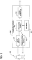
- Fig. 3 illustrates an exemplary computing device 300.
- each of system monitor 202 and data analyzer 206 are separate computing devices 300.
- system monitor 202 and data analyzer 206 may be incorporated into one computing device 300.
- Computing device 300 includes a processing device 302 and a database 304 coupled to processing device 302.
- Processing device 302 may include any processing unit, such as, without limitation, a central processing unit (CPU), an integrated circuit (IC), an application specific integrated circuit (ASIC), a microcomputer, a microcontroller, a programmable logic device (PLD), and/or any other programmable circuit.
- a processor may include multiple processing units (e.g., in a multi-core configuration).
- Database 304 is any device allowing information, such as executable instructions for processing device 302 and/or other data, to be stored and retrieved.
- a database may include, without limitation, one or more random access memory (RAM) devices, read only memory (ROM) devices, hard drive devices, flash memories, optical devices, and/or other computer-readable media.
- RAM random access memory
- ROM read only memory
- Stored in database 304 are, for example, computer-readable instructions for generating one or more profiles and/or probabilities of failure.
- database 304 may be configured to store operating data transmitted from one or more of turbines 100, anomaly alerts transmitted from one or more of turbines 100, and/or any other data suitable for use with the methods described herein.
- Computing device 300 includes a communication interface 310 that allows processing device 302 to communicate with network 204 and/or other computing devices 300 in communication with network 204. Additionally, a removable computer-readable media, such as a flash drive, CD-Rom, etc., may communicate with processing device 302 directly or via communication interface 310.
- a removable computer-readable media such as a flash drive, CD-Rom, etc.
- computing device 300 includes at least one presentation device 315 for presenting information to operator 320.
- Presentation device 315 is any component capable of conveying information to operator 320.
- Presentation device 315 may include, without limitation, a display device (e.g., a liquid crystal display (LCD), an organic light emitting diode (OLED) display, or "electronic ink” display) and/or an audio output device (e.g., a speaker or headphones).
- presentation device 315 is configured to present wind turbine information, such as the possible and/or actual power output of one or more wind turbines 100 (shown in Fig. 1 ) to operator 320.
- computing device 300 includes an input device 325 for receiving input from operator 320.
- Input device 325 may include, for example, a keyboard, a pointing device, a mouse, a touch sensitive panel (e.g., a touch pad or a touch screen), and/or other suitable input devices for receiving one or more inputs from operator 320.
- a single component, such as a touch screen, may function as both an output device of presentation device 315 and input device 325.
- database 304 includes operating data and anomaly alerts.
- the operating data and/or anomaly alerts may be generated by one or more of wind turbines 100. More specifically, operating data includes any parameters sensed and/or measured by sensors 114, as described above. Parameters may include, without limitation, phase voltage, phase current, power, wind speed, torque, temperatures, etc.
- operating data is transmitted from each of wind turbines 100 to system monitor 202, via network 204, and stored in database 304. Operating data may be transmitted from wind turbines 100 in various intervals and/or in real time.
- operating data may be received from one or more of sensors 114 and transmitted from controller 112 to system monitor 202 in intervals of, without limitation, about 10 minutes, about 5 minutes, about 1 minute, about 30 seconds, or about 10 seconds and/or other suitable intervals depending, for example on the type of network 204 and/or the number of turbines 100 coupled to system monitor 202.
- anomaly alerts may be generated and transmitted from one or more of wind turbines 100 to system monitor 202.
- an anomaly alert is generated when a parameter of turbine 100 falls outside of an expected range and/or violates a minimum/maximum expected value.
- Anomaly alerts may be stored in database 304 and may include, without limitation, a torque deviation, a line fault voltage, a fault current, a line fault frequency, an asymmetric generator current, a cabinet over temperature warning, grid voltage drop, feedback error circuit breaker, or other anomalies in the operation of wind turbine 100.
- Operating data and/or anomaly alerts stored in database 304 may be transmitted to data analyzer 206 in various suitable manners, such as via network 204, another network, and/or a computer-readable media, etc.
- processing device 302 determines a parametric profile for a component of wind turbine 100 from operating data of a plurality of wind turbines stored in database 304.
- the parametric profile defines one or more parametric events associated with the component prior to failure of the component.
- processing device 302 utilizes operating data related to parameters of components of wind turbines, such as, without limitation, a temperature associated with the component, a voltage and/or current associated with the component, etc., to identify a parametric event preceding historical failures of the component of wind turbine 100 to predict a failure of the component of wind turbine 100.
- processing device 302 when processing device 302 determines the parametric profile, selects a component associated with a particular failure of wind turbine 100. More specifically, several wind turbine failures may be reduced into discrete component failures, such as electronic component failures, through a "fishbone" analysis of the components, failures, and/or parameters. In one example, a failed rectifier circuit within controller 112 may cause a failure of wind turbine 100 (i.e., shutdown and/or reduction in power production, etc.). In another example, a cracked capacitor within controller 112 may cause a failure of wind turbine 100. Often, the failed component provides indicators of failure prior to actual failure. More specifically, operating data of turbine 100 may deviate from an expected value or range prior to failure of one or more components of turbine 100. The systems described herein, in some embodiments, select the component associated with the deviation to determine the parametric profile.
- selecting a component may be selected based on failure rates for the particular component. For example, if an insulated gate bi-polar transistor (IGBT) failure accounts for 4% of the turbine failures and 4% is high relative to other known failures, the IGBT may be selected by processing device 302 and/or operator 320 of data analyzer 206 as a component of interest. Moreover, the operating data and/or domain knowledge related to wind turbines 100 may identify a relevant portion of the operating data associated with the IGBT, such as operating voltage, switching types, current flow and/or switching speed, etc. It should be apparent that one or more other components of turbine 100 may include different parameters of interest usable to determine a parametric profile.
- IGBT insulated gate bi-polar transistor
- processing device 302 analyzes the operating data to indentify the parametric profile. Specifically, the processing device 302 employs various statistical tools to identify a parametric profile.
- the operating data includes actual torque for turbine 100 and an expected torque for turbine 100.
- Processing device 302 calculates a z-score for the relationship between the actual torque and the expected torque over time.
- Fig. 4 illustrates a graph 400 of the z-score 402 for turbine 100 under normal operation.
- Fig. 4 further illustrates a z-score 404 for turbine 100 during failure. As shown, z-score 402 deviates about 1.51, indicating a minimal difference between the actual torque and the set point torque.
- z-score 404 defines a growing deviation ranging up to about 18.57, indicating the deviation between the actual torque and the expected torque just prior to failure of turbine 100 at point 406.
- various different statistical tools may be employed to compare various types of operating data to expected values/ranges and/or other operating data. The types of parameters selected may be iterated to increase accuracy and efficiency of a parametric profile.
- processing device 302 may compare actual torque to wind speed, power output to wind speed, different phase currents, internal temperature to ambient temperature, phase voltages, or other combination of parameters suitable to predict component failures.
- domain knowledge may be used to assist in identifying a parametric profile. More specifically, domain knowledge may be used to provide expected values and/or set point values for analyzing the operating data. Domain knowledge may include, without limitation, expert knowledge of a theoretical operation of wind turbine 100, three-phase electricity generation, turbine response to specific environmental conditions, etc. In the example above, domain knowledge may be used to determine the expected torque for the wind turbine 100 under the appropriate conditions to gauge the actual torque of turbine 100 under those conditions.
- Operating data may be analyzed relative to a set point value to determine the parametric profile.
- processing device 302 may analyze the operating data relative to the set point value to detect whether the component and/or wind turbine 100 is deviating from the set point. Specifically, if the operating data overshoots/undershoots the set point value prior to failure of turbine 100, the overshooting/undershooting of the set point value may be determined as at least a portion of a parametric profile.
- a parametric event of the parametric profile may include overshooting/undershooting the set point value.
- processing device 302 compares one portion of operating data to another portion of the operating data to determine a parametric profile. Specifically, for example, processing device 302 may determine a parametric profile based on a comparison and/or analysis of torque versus wind speed, power versus wind speed, phase current differences, coolant temperature versus ambient temperature, phase voltage variations, etc.
- operating data may be analyzed based on a status of turbine 100. More specifically, operating data may include a designation of status for turbine 100, such as not running mode, startup mode, power producing mode, shutdown mode, etc. Operating data may be analyzed differently depending on a particular status of turbine 100. In one example, a torque deviation during a startup mode may be ignored, while a torque deviation during a power producing mode may be analyzed to determine the parametric profile. Accordingly, in various embodiments, processing device 302 may perform one or more processes described herein based on a turbine status of turbine 100. Specifically, in another example, processing device 302 may determine a previous turbine status and/or a present turbine status to analyze power output from turbine 100 relative to wind speed associated with turbine 100.
- processing device 302 validates the parametric profile historical data associated with a plurality of turbines, such as, operating data used to determine the parametric profile. Processing device 302 discards a parametric profile if a desired accuracy is not achieved. If a parametric profile predicts failures in non-failing turbines at a rate of about 15%, the parametric profile is discarded. Alternatively, processing device 302 weights the parametric profile according to its accuracy when determining the probability of failure. The validation of the parametric profile is employed to inhibit false positives. While repair of turbines 100 may be cumbersome, needless repairs of turbines 100 unnecessarily utilize available repair and/or maintenance resources.
- processing device 302 determines an anomaly profile for the component of wind turbine 100 from anomaly alerts generated by a plurality of wind turbines 100.
- the anomaly profile defines at least one anomaly associated with the component prior to failure of the component.
- processing device 302 determines the anomaly profile by filtering anomaly alerts from wind turbines 100 to identify anomalies associated with the component of turbine 100.
- processing device 302 and/or operator 320 uses domain knowledge to associate one or more anomaly alerts to a component of turbine 100.
- the domain knowledge may include the operational information about the component (e.g., a power converter, rectifier circuit, switching device, etc.), maintenance records, anomaly reports, etc.
- the anomaly alerts may be associated within multiple components and utilized to determine an anomaly profile for each of the components of turbine 100.
- processing device 302 may correlate the filter anomalies to determine the anomaly profile. More specifically, device 302 may use, for example, associative rule mining to determine the anomaly profile from the anomaly alerts. It should be appreciated that various analysis tools are available to determine an anomaly profile from the available anomaly alerts determined to be associated with a particular component of turbine 100.
- two turbines 100 generate anomaly alerts.
- First turbine 100 transmits the following anomalies: a restart delay at day 1, a restart delay at day 14, a generator side CCU collective fault at day 14, and a torque deviation at day 15, prior to turbine failure on day 17.
- Second turbine 100 transmits the following anomalies: a shutdown at day 1, a generator side CCU collective fault at day 23, a torque deviation at day 23, and a line CCU fault current on day 23, prior to turbine failure on day 29.
- processing device 302 may determine an anomaly profile including the two anomalies.
- the anomaly profile may include a torque deviation and a generator side CCU collective fault.
- an anomaly alert may persist for an interval of time. More specifically, a line fault frequency alert may persist for two days, without resolution by turbine restart.
- processing device 302 may determine an anomaly profile including a persistence line fault frequency alert. It should be appreciated that the number and/or type of anomalies included in an anomaly profile may be different in other embodiments.
- processing device 302 may further validate the anomaly profile against the anomaly alerts to determine a validation score.
- the validation score may indicate the accuracy of the anomaly profile, i.e., the number of false positives.
- the anomaly profile may be discarded if the validation score exceeds a predetermined value.
- the validation score may be used by processing device 302 to weight the anomaly profile according to its accuracy when determining the probability of failure.
- processing device 302 When processing device 302 has determined the parametric profile and the anomaly profiles, processing device 302 is configured to determine a probability of failure for the component of wind turbine 100 based on the parametric profile and the anomaly profile.
- the probability of failure may include a likelihood of a failure and/or a predicted timing of a failure. In this manner, a probability of failure is provided for a component of wind turbine 100, when the parametric events and/or the anomalies occur, such that an operator of wind turbine 100 may pre-plan for failure of wind turbine 100 to minimize and/or eliminate down time of wind turbine 100 due to a failure associated with the component.
- probabilities of failure may be incorporated into system monitor 202.
- probabilities of failure may be coded and/or converted into one or more SQL queries.
- the SQL queries may be called by a SCADA component or incorporated into a SCADA component of system monitor 202.
- the SQL queries may be run continuously, periodically, and/or upon operator request to determine if one of more parametric events and/or anomalies upon which the probability of failure is based has occurred.
- system monitor 202 may assign the probability of failure to wind turbine 100.
- an operator at system monitor 202 may initiate a procedure to procure maintenance for the turbine 100.
- the operator may be able to minimize and/or eliminate down time of wind turbine 100 due to a failure associated with the component.
- data analyzer 206 provides improved reliability, availability and maintainability of wind turbines 100, and consequently, turbine farm system 200. More particularly, the systems and methods described herein may permit an operator of turbine farm system 200 to plan outages, maintenance activities, spare parts inventories, and personnel in advance of wind turbine failures, while reducing down time associated with failed wind turbines.
- Fig. 5 illustrates an exemplary method 500 for assigning a probability of failure to a turbine.
- Method 500 may be performed by any suitable computing device, including, for example, data analyzer 206 of Fig. 2 .
- computing device 300 disclosed herein is not limited to method 500, but may be used to perform other methods consistent with the present disclosure.
- Method 500 includes determining 502 a parametric profile for a component of a wind turbine from operating data of a plurality of wind turbines, determining 504 an anomaly profile for the component of the wind turbine from anomaly alerts from a plurality of wind turbines, and determining 506 a probability of failure for the component of the wind turbine based on the parametric profile and the anomaly profile.
- the parametric profile defines at least one parametric event associated with the component prior to failure of the component
- the anomaly profile defines at least one anomaly associated with the component prior to failure of the component.
- determining 502 the parametric profile includes analyzing at least one parameter of the component relative to one of an expected value and a set point.
- analyzing at least one parameter may include analyzing the at least one parameter based on a turbine status.
- determining 502 the parametric profile may include analyzing at least one parameter of the component relative to a second parameter associated with the wind turbine.
- determining 506 the probability of failure includes determining the failure score based on domain knowledge. More specifically, domain knowledge may be employed to determine the parametric profile, to determine the anomaly profile, and/or combine the parametric profile and the anomaly profile to determine the probability of failure. Domain knowledge may include, without limitation, maintenance records, theoretical operations of wind turbine 100, etc.
- method 500 may include assigning the probability of failure to a wind turbine based on an occurrence of the at least one parametric event and the at least one anomaly.
- determining 504 the anomaly profile includes identifying anomaly alerts associated with the component. Moreover, determining 504 the anomaly profile may include validating the anomaly profile against the anomaly alerts to determine a validation score. Further still, determining 506 the probability of failure may include weighting the anomaly profile based on at least the validation score.
- One or more of the above described embodiments may provide accurate predictions of wind turbines failures based on historical operating data and anomaly alerts from a plurality of wind turbines. More specifically, the systems and methods described herein may permit an operator of a turbine farm system to plan outages, maintenance activities, spare parts inventories, and personnel in advance of wind turbine failures, while reducing down time associated with failed wind turbines. Moreover, the systems and methods described herein may provide enhanced management of service offerings and contract management.
- Embodiments provided herein facilitate generating one or more probabilities of failure usable to predict a turbine failure prior to the failure.
- Exemplary embodiments of computing devices and turbine systems are described above in detail. The systems and methods are not limited to the specific embodiments described herein, but rather each component may be utilized independently and separately from other components described herein.
- an exemplary technical effect may include at least one of: (a) determining a parametric profile for a component of a wind turbine from operating data of a plurality of wind turbines, (b) determining an anomaly profile for the component of the wind turbine from anomaly alerts generated by a plurality of wind turbines, and (c) includes determining a probability of failure for the component of the wind turbine based on the parametric profile and the anomaly profile.
Landscapes
- Engineering & Computer Science (AREA)
- Sustainable Energy (AREA)
- General Physics & Mathematics (AREA)
- Automation & Control Theory (AREA)
- Life Sciences & Earth Sciences (AREA)
- Sustainable Development (AREA)
- Physics & Mathematics (AREA)
- Chemical & Material Sciences (AREA)
- Combustion & Propulsion (AREA)
- Mechanical Engineering (AREA)
- General Engineering & Computer Science (AREA)
- Wind Motors (AREA)
- Control Of Positive-Displacement Air Blowers (AREA)
- Structures Of Non-Positive Displacement Pumps (AREA)
Description
- The subject matter described herein relates generally to wind turbines and, more particularly, to predicting wind turbine component failures.
- Wind turbines are known to be located in various settings suitable to capture wind energy. Wind turbines generally provide variable performance based on environmental conditions associated with the wind turbines during operation, as well as fitness of the wind turbines to function properly. Wind turbines often utilize sensors to monitor wind turbine performance and wind turbine components during operation. At least some of these sensors may be used to detect malfunctions of the wind turbines.
- Often, malfunctions require that the wind turbine be shut down, inspected, and/or reset. The logistics of sending a team to the wind turbine may be onerous given the location of the wind turbine, such as at a height unreachable without specific equipment and/or positioned out at sea. In addition, downtime associated with inspection and/or repair of the wind turbine inhibits its ability to generate energy. Accordingly, once a wind turbine fails, it may take several days and/or weeks to organize the appropriate equipment and/or parts to return the wind turbine to working order.
- Various wind turbine condition and health monitoring systems are known, for example, from
US 2010/0138267 andUS 2011/0125419 . - It is an object of the invention to provide a data analyzer for use in predicting a wind turbine component failure.
- The invention is defined in the appended claims.
- Various aspects and embodiments of the present invention will now be described in connection with the accompanying drawings, in which:
-
Fig. 1 is a perspective view of an exemplary wind turbine. -
Fig. 2 is a block diagram illustrating an exemplary turbine farm system. -
Fig. 3 is a block diagram illustrating an exemplary computing device. -
Fig. 4 is a graph illustrating torque output of a functional wind turbine, such as the wind turbine shown inFig. 1 , relative to torque output of a failing wind turbine. -
Fig. 5 is a flowchart of an exemplary method for use in predicting a wind turbine component failure. - Various of the embodiments described herein facilitate predicting a wind turbine component failure.
-
Fig. 1 is a perspective view of anexemplary wind turbine 100, including anacelle 102 that houses a generator (not shown inFig. 1 ). Nacelle 102 is mounted on a tower 104 (only a portion oftower 104 is shown inFig. 1 ) thattower 104 may have any suitable height to facilitate operation ofwind turbine 100 as described herein. In an exemplary embodiment,wind turbine 100 also includes arotor 106 having threerotor blades 108 coupled to a rotatinghub 110. Alternatively,wind turbine 100 may include any number ofrotor blades 108 that enable operation ofwind turbine 100 as described herein. In an exemplary embodiment,wind turbine 100 includes a gearbox (not shown) that is rotatingly coupled torotor 106 and to the generator. - In some embodiments,
wind turbine 100 includes acontroller 112 and one ormore sensors 114.Sensors 114 provide operating data aboutturbine 100. In one embodiment, sensor(s) 114 include one or more of a wind speed and/or a direction sensor (e.g., an anemometer), an ambient air temperature sensor, a component temperature sensor, a controller temperature sensor, an air density sensor, an atmospheric pressure sensor, a humidity sensor, a rotor torque sensor, a voltage sensor, a current sensor, a power sensor, a blade pitch angle sensor, a rotor speed sensor, and/or other sensor suitable for use withwind turbine 100.Sensors 114 sense operating parameters at the turbine-level, such as rotor speed, and/or at a component-level, such as a voltage across a switching device. A component may include any subassembly ofturbine 100. For example,controller 112 may be a component, while a switching device withincontroller 112 may be a component. - Each
sensor 114 is located according to its function. For example, an anemometer may be positioned on an outside surface ofnacelle 102, such that the anemometer is exposed to air surroundingwind turbine 100. Eachsensor 114 generates and transmits one or more signals corresponding to a detected operating condition. Moreover, eachsensor 114 may transmit a signal continuously, periodically, or only once, for example, though other signal timings are also contemplated.Sensors 114 are coupled tocontroller 112, andcontroller 112 receives operating data from each ofsensors 114. Moreover,controller 112 is configured to control an operation ofwind turbine 100 and may include, without limitation, a brake, a relay, a motor, a solenoid, and/or a servomechanism. Further,controller 112 may be configured to adjust a physical configuration ofwind turbine 100, such as an angle or pitch ofrotor blades 108 and/or an orientation ofnacelle 102 orrotor 106 with respect totower 104. -
Fig. 2 illustrates an exemplaryturbine farm system 200. In the exemplary embodiment,turbine farm system 200 includesmultiple wind turbines 100.Turbine farm system 200 includes asystem monitor 202 coupled to each ofwind turbines 100. System monitor 202 monitors and/or controls each ofwind turbines 100. For example,system monitor 202 may include a supervisory control and data acquisition (SCADA) system.System monitor 202 is coupled to each ofwind turbines 100 throughnetwork 204.Network 204 may include, without limitation, the Internet, a local area network (LAN), a wide area network (WAN), a wireless LAN, a mesh network, and/or a virtual private network (VPN). - Turbine
farm system 200 includesdata analyzer 206. In the exemplary embodiment,data analyzer 206 is communicatively coupled tosystem monitor 202. For example,data analyzer 206 may be connected directly tosystem monitor 202 throughcommunication channel 208 and/or connected tosystem monitor 202 through a network, such asnetwork 204. Alternatively,data analyzer 206 may be segregated fromsystem monitor 202, such that data transfer requires physically transferring a removable computer-readable media, such as a flash drive or CD-ROM, betweendata analyzer 206 andsystem monitor 202. -
Fig. 3 illustrates anexemplary computing device 300. In the exemplary embodiment, each ofsystem monitor 202 anddata analyzer 206 areseparate computing devices 300. In at least one embodiment,system monitor 202 anddata analyzer 206 may be incorporated into onecomputing device 300.Computing device 300 includes aprocessing device 302 and adatabase 304 coupled toprocessing device 302.Processing device 302 may include any processing unit, such as, without limitation, a central processing unit (CPU), an integrated circuit (IC), an application specific integrated circuit (ASIC), a microcomputer, a microcontroller, a programmable logic device (PLD), and/or any other programmable circuit. A processor may include multiple processing units (e.g., in a multi-core configuration). -
Database 304 is any device allowing information, such as executable instructions forprocessing device 302 and/or other data, to be stored and retrieved. A database may include, without limitation, one or more random access memory (RAM) devices, read only memory (ROM) devices, hard drive devices, flash memories, optical devices, and/or other computer-readable media. Stored indatabase 304 are, for example, computer-readable instructions for generating one or more profiles and/or probabilities of failure. In addition, or alternatively,database 304 may be configured to store operating data transmitted from one or more ofturbines 100, anomaly alerts transmitted from one or more ofturbines 100, and/or any other data suitable for use with the methods described herein. -
Computing device 300 includes acommunication interface 310 that allowsprocessing device 302 to communicate withnetwork 204 and/orother computing devices 300 in communication withnetwork 204. Additionally, a removable computer-readable media, such as a flash drive, CD-Rom, etc., may communicate withprocessing device 302 directly or viacommunication interface 310. - In some embodiments,
computing device 300 includes at least onepresentation device 315 for presenting information tooperator 320.Presentation device 315 is any component capable of conveying information tooperator 320.Presentation device 315 may include, without limitation, a display device (e.g., a liquid crystal display (LCD), an organic light emitting diode (OLED) display, or "electronic ink" display) and/or an audio output device (e.g., a speaker or headphones). In some embodiments,presentation device 315 is configured to present wind turbine information, such as the possible and/or actual power output of one or more wind turbines 100 (shown inFig. 1 ) tooperator 320. - In some embodiments,
computing device 300 includes aninput device 325 for receiving input fromoperator 320.Input device 325 may include, for example, a keyboard, a pointing device, a mouse, a touch sensitive panel (e.g., a touch pad or a touch screen), and/or other suitable input devices for receiving one or more inputs fromoperator 320. A single component, such as a touch screen, may function as both an output device ofpresentation device 315 andinput device 325. - In the exemplary embodiment,
database 304 includes operating data and anomaly alerts. The operating data and/or anomaly alerts may be generated by one or more ofwind turbines 100. More specifically, operating data includes any parameters sensed and/or measured bysensors 114, as described above. Parameters may include, without limitation, phase voltage, phase current, power, wind speed, torque, temperatures, etc. In the exemplary embodiment, operating data is transmitted from each ofwind turbines 100 to system monitor 202, vianetwork 204, and stored indatabase 304. Operating data may be transmitted fromwind turbines 100 in various intervals and/or in real time. Specifically, for example, operating data may be received from one or more ofsensors 114 and transmitted fromcontroller 112 to system monitor 202 in intervals of, without limitation, about 10 minutes, about 5 minutes, about 1 minute, about 30 seconds, or about 10 seconds and/or other suitable intervals depending, for example on the type ofnetwork 204 and/or the number ofturbines 100 coupled to system monitor 202. - In addition to operating data, anomaly alerts may be generated and transmitted from one or more of
wind turbines 100 to system monitor 202. In general, an anomaly alert is generated when a parameter ofturbine 100 falls outside of an expected range and/or violates a minimum/maximum expected value. Anomaly alerts may be stored indatabase 304 and may include, without limitation, a torque deviation, a line fault voltage, a fault current, a line fault frequency, an asymmetric generator current, a cabinet over temperature warning, grid voltage drop, feedback error circuit breaker, or other anomalies in the operation ofwind turbine 100. Operating data and/or anomaly alerts stored indatabase 304 may be transmitted todata analyzer 206 in various suitable manners, such as vianetwork 204, another network, and/or a computer-readable media, etc. - During operation,
processing device 302 determines a parametric profile for a component ofwind turbine 100 from operating data of a plurality of wind turbines stored indatabase 304. The parametric profile defines one or more parametric events associated with the component prior to failure of the component. As such,processing device 302 utilizes operating data related to parameters of components of wind turbines, such as, without limitation, a temperature associated with the component, a voltage and/or current associated with the component, etc., to identify a parametric event preceding historical failures of the component ofwind turbine 100 to predict a failure of the component ofwind turbine 100. - In some embodiments, when processing
device 302 determines the parametric profile,processing device 302 selects a component associated with a particular failure ofwind turbine 100. More specifically, several wind turbine failures may be reduced into discrete component failures, such as electronic component failures, through a "fishbone" analysis of the components, failures, and/or parameters. In one example, a failed rectifier circuit withincontroller 112 may cause a failure of wind turbine 100 (i.e., shutdown and/or reduction in power production, etc.). In another example, a cracked capacitor withincontroller 112 may cause a failure ofwind turbine 100. Often, the failed component provides indicators of failure prior to actual failure. More specifically, operating data ofturbine 100 may deviate from an expected value or range prior to failure of one or more components ofturbine 100. The systems described herein, in some embodiments, select the component associated with the deviation to determine the parametric profile. - In the exemplary embodiment, selecting a component may be selected based on failure rates for the particular component. For example, if an insulated gate bi-polar transistor (IGBT) failure accounts for 4% of the turbine failures and 4% is high relative to other known failures, the IGBT may be selected by processing
device 302 and/oroperator 320 of data analyzer 206 as a component of interest. Moreover, the operating data and/or domain knowledge related towind turbines 100 may identify a relevant portion of the operating data associated with the IGBT, such as operating voltage, switching types, current flow and/or switching speed, etc. It should be apparent that one or more other components ofturbine 100 may include different parameters of interest usable to determine a parametric profile. - Once the component and operating data have been selected by processing
device 302 and/oroperator 320,processing device 302 analyzes the operating data to indentify the parametric profile. Specifically, theprocessing device 302 employs various statistical tools to identify a parametric profile. The operating data includes actual torque forturbine 100 and an expected torque forturbine 100.Processing device 302 calculates a z-score for the relationship between the actual torque and the expected torque over time.Fig. 4 illustrates a graph 400 of the z-score 402 forturbine 100 under normal operation.Fig. 4 further illustrates a z-score 404 forturbine 100 during failure. As shown, z-score 402 deviates about 1.51, indicating a minimal difference between the actual torque and the set point torque. Conversely, z-score 404 defines a growing deviation ranging up to about 18.57, indicating the deviation between the actual torque and the expected torque just prior to failure ofturbine 100 atpoint 406. As should be apparent, various different statistical tools may be employed to compare various types of operating data to expected values/ranges and/or other operating data. The types of parameters selected may be iterated to increase accuracy and efficiency of a parametric profile. For example,processing device 302 may compare actual torque to wind speed, power output to wind speed, different phase currents, internal temperature to ambient temperature, phase voltages, or other combination of parameters suitable to predict component failures. - In various embodiments, domain knowledge may be used to assist in identifying a parametric profile. More specifically, domain knowledge may be used to provide expected values and/or set point values for analyzing the operating data. Domain knowledge may include, without limitation, expert knowledge of a theoretical operation of
wind turbine 100, three-phase electricity generation, turbine response to specific environmental conditions, etc. In the example above, domain knowledge may be used to determine the expected torque for thewind turbine 100 under the appropriate conditions to gauge the actual torque ofturbine 100 under those conditions. - Operating data may be analyzed relative to a set point value to determine the parametric profile. In the exemplary embodiment,
processing device 302 may analyze the operating data relative to the set point value to detect whether the component and/orwind turbine 100 is deviating from the set point. Specifically, if the operating data overshoots/undershoots the set point value prior to failure ofturbine 100, the overshooting/undershooting of the set point value may be determined as at least a portion of a parametric profile. In such an example, a parametric event of the parametric profile may include overshooting/undershooting the set point value. - It should be appreciated that various different operations may be performed to determine a parametric profile including at least one parametric event. In several embodiments,
processing device 302 compares one portion of operating data to another portion of the operating data to determine a parametric profile. Specifically, for example,processing device 302 may determine a parametric profile based on a comparison and/or analysis of torque versus wind speed, power versus wind speed, phase current differences, coolant temperature versus ambient temperature, phase voltage variations, etc. - Additionally, in the exemplary embodiment, operating data may be analyzed based on a status of
turbine 100. More specifically, operating data may include a designation of status forturbine 100, such as not running mode, startup mode, power producing mode, shutdown mode, etc. Operating data may be analyzed differently depending on a particular status ofturbine 100. In one example, a torque deviation during a startup mode may be ignored, while a torque deviation during a power producing mode may be analyzed to determine the parametric profile. Accordingly, in various embodiments,processing device 302 may perform one or more processes described herein based on a turbine status ofturbine 100. Specifically, in another example,processing device 302 may determine a previous turbine status and/or a present turbine status to analyze power output fromturbine 100 relative to wind speed associated withturbine 100. - Further,
processing device 302 validates the parametric profile historical data associated with a plurality of turbines, such as, operating data used to determine the parametric profile.Processing device 302 discards a parametric profile if a desired accuracy is not achieved. If a parametric profile predicts failures in non-failing turbines at a rate of about 15%, the parametric profile is discarded. Alternatively,processing device 302 weights the parametric profile according to its accuracy when determining the probability of failure. The validation of the parametric profile is employed to inhibit false positives. While repair ofturbines 100 may be cumbersome, needless repairs ofturbines 100 unnecessarily utilize available repair and/or maintenance resources. - In the exemplary embodiment,
processing device 302 determines an anomaly profile for the component ofwind turbine 100 from anomaly alerts generated by a plurality ofwind turbines 100. The anomaly profile defines at least one anomaly associated with the component prior to failure of the component. - In various embodiments,
processing device 302 determines the anomaly profile by filtering anomaly alerts fromwind turbines 100 to identify anomalies associated with the component ofturbine 100. In the exemplary embodiment,processing device 302 and/oroperator 320 uses domain knowledge to associate one or more anomaly alerts to a component ofturbine 100. The domain knowledge may include the operational information about the component (e.g., a power converter, rectifier circuit, switching device, etc.), maintenance records, anomaly reports, etc. The anomaly alerts may be associated within multiple components and utilized to determine an anomaly profile for each of the components ofturbine 100. - Additionally, or alternatively,
processing device 302 may correlate the filter anomalies to determine the anomaly profile. More specifically,device 302 may use, for example, associative rule mining to determine the anomaly profile from the anomaly alerts. It should be appreciated that various analysis tools are available to determine an anomaly profile from the available anomaly alerts determined to be associated with a particular component ofturbine 100. - Specifically, in one example, two
turbines 100 generate anomaly alerts.First turbine 100 transmits the following anomalies: a restart delay atday 1, a restart delay at day 14, a generator side CCU collective fault at day 14, and a torque deviation atday 15, prior to turbine failure on day 17.Second turbine 100 transmits the following anomalies: a shutdown atday 1, a generator side CCU collective fault at day 23, a torque deviation at day 23, and a line CCU fault current on day 23, prior to turbine failure on day 29. Because each of the two failed turbines issue common anomaly alerts prior to failure,processing device 302 may determine an anomaly profile including the two anomalies. Particularly, in this example, the anomaly profile may include a torque deviation and a generator side CCU collective fault. In another example, an anomaly alert may persist for an interval of time. More specifically, a line fault frequency alert may persist for two days, without resolution by turbine restart. In such an example,processing device 302 may determine an anomaly profile including a persistence line fault frequency alert. It should be appreciated that the number and/or type of anomalies included in an anomaly profile may be different in other embodiments. - In the exemplary embodiment,
processing device 302 may further validate the anomaly profile against the anomaly alerts to determine a validation score. The validation score may indicate the accuracy of the anomaly profile, i.e., the number of false positives. The anomaly profile may be discarded if the validation score exceeds a predetermined value. Alternatively, the validation score may be used by processingdevice 302 to weight the anomaly profile according to its accuracy when determining the probability of failure. - When processing
device 302 has determined the parametric profile and the anomaly profiles,processing device 302 is configured to determine a probability of failure for the component ofwind turbine 100 based on the parametric profile and the anomaly profile. The probability of failure may include a likelihood of a failure and/or a predicted timing of a failure. In this manner, a probability of failure is provided for a component ofwind turbine 100, when the parametric events and/or the anomalies occur, such that an operator ofwind turbine 100 may pre-plan for failure ofwind turbine 100 to minimize and/or eliminate down time ofwind turbine 100 due to a failure associated with the component. - One or more probabilities of failure may be incorporated into system monitor 202. Specifically, for example, probabilities of failure may be coded and/or converted into one or more SQL queries. The SQL queries may be called by a SCADA component or incorporated into a SCADA component of system monitor 202. The SQL queries may be run continuously, periodically, and/or upon operator request to determine if one of more parametric events and/or anomalies upon which the probability of failure is based has occurred.
- More specifically, when system monitor 202 recognizes occurrence of one or more parametric events and anomalies indicative of the parametric profile and anomaly profiles, system monitor 202 may assign the probability of failure to
wind turbine 100. Depending on the severity of the probability of failure an operator at system monitor 202 may initiate a procedure to procure maintenance for theturbine 100. As indicated above, the operator may be able to minimize and/or eliminate down time ofwind turbine 100 due to a failure associated with the component. In this manner,data analyzer 206 provides improved reliability, availability and maintainability ofwind turbines 100, and consequently,turbine farm system 200. More particularly, the systems and methods described herein may permit an operator ofturbine farm system 200 to plan outages, maintenance activities, spare parts inventories, and personnel in advance of wind turbine failures, while reducing down time associated with failed wind turbines. -
Fig. 5 illustrates anexemplary method 500 for assigning a probability of failure to a turbine.Method 500 may be performed by any suitable computing device, including, for example,data analyzer 206 ofFig. 2 . Furthermore, it should be appreciated thatcomputing device 300 disclosed herein is not limited tomethod 500, but may be used to perform other methods consistent with the present disclosure. -
Method 500 includes determining 502 a parametric profile for a component of a wind turbine from operating data of a plurality of wind turbines, determining 504 an anomaly profile for the component of the wind turbine from anomaly alerts from a plurality of wind turbines, and determining 506 a probability of failure for the component of the wind turbine based on the parametric profile and the anomaly profile. The parametric profile defines at least one parametric event associated with the component prior to failure of the component, and the anomaly profile defines at least one anomaly associated with the component prior to failure of the component. - In the exemplary embodiment, determining 502 the parametric profile includes analyzing at least one parameter of the component relative to one of an expected value and a set point. In one example, analyzing at least one parameter may include analyzing the at least one parameter based on a turbine status. Further, in some embodiments, determining 502 the parametric profile may include analyzing at least one parameter of the component relative to a second parameter associated with the wind turbine.
- In various embodiments, determining 506 the probability of failure includes determining the failure score based on domain knowledge. More specifically, domain knowledge may be employed to determine the parametric profile, to determine the anomaly profile, and/or combine the parametric profile and the anomaly profile to determine the probability of failure. Domain knowledge may include, without limitation, maintenance records, theoretical operations of
wind turbine 100, etc. - Additionally,
method 500 may include assigning the probability of failure to a wind turbine based on an occurrence of the at least one parametric event and the at least one anomaly. - In several embodiments, determining 504 the anomaly profile includes identifying anomaly alerts associated with the component. Moreover, determining 504 the anomaly profile may include validating the anomaly profile against the anomaly alerts to determine a validation score. Further still, determining 506 the probability of failure may include weighting the anomaly profile based on at least the validation score.
- One or more of the above described embodiments may provide accurate predictions of wind turbines failures based on historical operating data and anomaly alerts from a plurality of wind turbines. More specifically, the systems and methods described herein may permit an operator of a turbine farm system to plan outages, maintenance activities, spare parts inventories, and personnel in advance of wind turbine failures, while reducing down time associated with failed wind turbines. Moreover, the systems and methods described herein may provide enhanced management of service offerings and contract management.
- Embodiments provided herein facilitate generating one or more probabilities of failure usable to predict a turbine failure prior to the failure. Exemplary embodiments of computing devices and turbine systems are described above in detail. The systems and methods are not limited to the specific embodiments described herein, but rather each component may be utilized independently and separately from other components described herein.
- The methods and systems described herein may be implemented using computer programming or engineering techniques including computer software, firmware, hardware or any combination or subset thereof, wherein an exemplary technical effect may include at least one of: (a) determining a parametric profile for a component of a wind turbine from operating data of a plurality of wind turbines, (b) determining an anomaly profile for the component of the wind turbine from anomaly alerts generated by a plurality of wind turbines, and (c) includes determining a probability of failure for the component of the wind turbine based on the parametric profile and the anomaly profile.
- This written description uses examples to disclose the invention, including the preferred mode, and also to enable any person skilled in the art to practice the invention, including making and using any devices or systems and performing any incorporated methods.
Claims (8)
- A data analyzer (206) for use in predicting a wind turbine component failure, said data analyzer comprising:a database (304) including operating data and anomaly alerts for a plurality of wind turbines (100) anda processing device (302) coupled to said database; the processing device configured to:determine a parametric profile for a component of a wind turbine from the operating data by calculating a Z-score for the relationship between the operating data and expected operating data for the component over time, wherein the anomaly alerts are generated when a component parameter falls outside of an expected range, and the parametric profile defining at least one parametric event associated with the component prior to failure of the component;determine an anomaly profile for the component of the wind turbine from the anomaly alerts, the anomaly profile defining at least one anomaly associated with the component prior to failure of the component;determine a probability of failure for the component of the wind turbine based on the parametric profile and the anomaly profile;characterized in that the processing device (302) is further configured to: identify anomaly alerts associated with the component; validate the accuracy of the anomaly profile based on the anomaly alerts;and select the anomaly profile that exceed a threshold accuracy in order to determine the anomaly profile; andvalidate the operating data used to determine the parametric profile by discarding a parametric profile if a desired accuracy is not achieved or by weighting a parametric profile according to its accuracy when determining the probability of failure.
- The data analyzer (206) of claim 1, further comprising a communication interface (310) for coupling to at least one of a network (204) and a system monitor (202) to receive said operating data and said anomaly alerts.
- The data analyzer (206) of any preceding claim, wherein the processing device (302) is configured to assign the probability of failure to a wind turbine (100) based on an occurrence of the at least one parametric event and the at least one anomaly.
- The data analyzer (206) of any preceding claim, wherein the at least one parametric event comprises a correlation between a wind speed and a torque output of a wind turbine (100).
- The data analyzer (206) of any preceding claim , wherein said processing device (302) is configured to analyze at least one parameter of the component relative to one of an expected value and a set point to determine the parametric profile.
- The data analyzer (206) of claim 5, wherein said processing device (302) is configured to analyze the at least one parameter based on a turbine status.
- The data analyzer (206) of claim 5 or 6, wherein the at least one parameter includes at least one of voltage, current, power, wind speed, torque, and temperature associated with the wind turbine.
- The data analyzer (206) of any preceding claim, wherein said processing device (302) is configured to determine the probability of failure based on domain knowledge.
Applications Claiming Priority (1)
| Application Number | Priority Date | Filing Date | Title |
|---|---|---|---|
| US13/237,073 US8326577B2 (en) | 2011-09-20 | 2011-09-20 | System and method for predicting wind turbine component failures |
Publications (3)
| Publication Number | Publication Date |
|---|---|
| EP2573390A2 EP2573390A2 (en) | 2013-03-27 |
| EP2573390A3 EP2573390A3 (en) | 2013-09-25 |
| EP2573390B1 true EP2573390B1 (en) | 2021-04-21 |
Family
ID=46163049
Family Applications (1)
| Application Number | Title | Priority Date | Filing Date |
|---|---|---|---|
| EP12184170.4A Active EP2573390B1 (en) | 2011-09-20 | 2012-09-13 | System and method for predicting wind turbine component failures |
Country Status (5)
| Country | Link |
|---|---|
| US (1) | US8326577B2 (en) |
| EP (1) | EP2573390B1 (en) |
| CN (1) | CN103016264B (en) |
| DK (1) | DK2573390T3 (en) |
| ES (1) | ES2881184T3 (en) |
Families Citing this family (46)
| Publication number | Priority date | Publication date | Assignee | Title |
|---|---|---|---|---|
| US10254270B2 (en) | 2006-11-16 | 2019-04-09 | General Electric Company | Sensing system and method |
| DE102007060958A1 (en) * | 2007-12-14 | 2009-06-25 | Repower Systems Ag | Control device for wind turbines with power failure detection |
| US8334610B2 (en) * | 2009-02-13 | 2012-12-18 | Robert Migliori | Gearless pitch control mechanism for starting, stopping and regulating the power output of wind turbines without the use of a brake |
| US8988237B2 (en) | 2010-05-27 | 2015-03-24 | University Of Southern California | System and method for failure prediction for artificial lift systems |
| US8988236B2 (en) | 2010-05-27 | 2015-03-24 | University Of Southern California | System and method for failure prediction for rod pump artificial lift systems |
| GB201110003D0 (en) * | 2011-06-14 | 2011-07-27 | Romax Technology Ltd | Identifying wind turbines for maintenance |
| US9280517B2 (en) * | 2011-06-23 | 2016-03-08 | University Of Southern California | System and method for failure detection for artificial lift systems |
| US9157308B2 (en) * | 2011-12-29 | 2015-10-13 | Chevron U.S.A. Inc. | System and method for prioritizing artificial lift system failure alerts |
| JP2013170566A (en) * | 2012-02-23 | 2013-09-02 | Mitsubishi Heavy Ind Ltd | Monitoring method and system for wind turbine generator |
| US8872363B2 (en) * | 2012-05-11 | 2014-10-28 | Bader Abdullah ALMALKI | Vehicle movement activated electrical power generator, and method for providing electrical power for roadside applications |
| US9239894B2 (en) * | 2012-07-23 | 2016-01-19 | General Electric Company | Systems and methods for predicting failures in power systems equipment |
| ES2613305T3 (en) * | 2013-01-25 | 2017-05-23 | Vestas Wind Systems A/S | Wind turbine control |
| EP2804064B1 (en) * | 2013-05-17 | 2020-07-01 | ABB S.p.A. | A computerised system and method for generating a life expectancy analysis report related to a low or medium voltage switching device |
| US11055450B2 (en) * | 2013-06-10 | 2021-07-06 | Abb Power Grids Switzerland Ag | Industrial asset health model update |
| US10534361B2 (en) * | 2013-06-10 | 2020-01-14 | Abb Schweiz Ag | Industrial asset health model update |
| CN103324854A (en) * | 2013-06-26 | 2013-09-25 | 广东电网公司电力科学研究院 | Method and system for evaluating reliability of wind power collection system of offshore wind power plant |
| EP2881821A1 (en) * | 2013-12-05 | 2015-06-10 | Blue Yonder GmbH | Processor core array for characterizing behavior properties of equipment, and method |
| US10169051B2 (en) | 2013-12-05 | 2019-01-01 | Blue Yonder GmbH | Data processing device, processor core array and method for characterizing behavior of equipment under observation |
| EP2881820A1 (en) * | 2013-12-05 | 2015-06-10 | Blue Yonder GmbH | Data processing device and method for characterizing behavior of equipment under observation |
| US9823311B2 (en) * | 2014-07-31 | 2017-11-21 | Schneider Electric USA, Inc. | System to identify potential electrical network faults combining vibration and power quality analysis |
| KR20160017681A (en) * | 2014-07-31 | 2016-02-17 | 두산중공업 주식회사 | System and method for managing wind plant |
| US10584681B2 (en) | 2014-12-19 | 2020-03-10 | Micro Focus Llc | Automative system management |
| US11107169B2 (en) * | 2015-11-18 | 2021-08-31 | General Electric Company | Systems and methods for controlling and monitoring power assets |
| JP2019113883A (en) * | 2016-03-25 | 2019-07-11 | 株式会社日立製作所 | Utilization assisting apparatus and wind power generation system |
| KR101768810B1 (en) * | 2016-06-02 | 2017-08-30 | 두산중공업 주식회사 | Wind farm supervision monitoring system |
| JP6736987B2 (en) * | 2016-06-03 | 2020-08-05 | 日本精工株式会社 | Condition monitoring device for rotating parts of wind power generator |
| CN108226775B (en) * | 2016-12-13 | 2020-06-30 | 北京金风科创风电设备有限公司 | Fault self-detection method and device of wind driven generator |
| US10969933B1 (en) * | 2017-02-07 | 2021-04-06 | The Mathworks, Inc. | Graphical representation of ordered model items based on solver information |
| CN106951997B (en) * | 2017-03-24 | 2020-11-10 | 新疆金风科技股份有限公司 | Method and device for predicting fault of fan |
| US20200118012A1 (en) * | 2017-04-18 | 2020-04-16 | Hewlett-Packard Development Company, L.P. | Monitoring the Thermal Health of an Electronic Device |
| US11549491B2 (en) | 2017-06-14 | 2023-01-10 | Kk Wind Solutions A/S | Independent monitoring system for a wind turbine |
| CN109139388B (en) * | 2017-06-15 | 2020-11-10 | 北京国电思达科技有限公司 | Intelligent auxiliary monitoring system of wind driven generator |
| CN109386435B (en) * | 2017-08-04 | 2021-01-01 | 阿里巴巴集团控股有限公司 | Wind turbine generator fault monitoring method, device and system |
| US11663496B2 (en) * | 2018-01-30 | 2023-05-30 | Utopus Insights, Inc. | System and method for predicting failure of components using temporal scoping of sensor data |
| JP7460545B2 (en) * | 2018-03-28 | 2024-04-02 | エルアンドティー テクノロジー サービシズ リミテッド | System and method for monitoring the health of electromechanical machines and predicting failures |
| US11080438B2 (en) * | 2018-05-30 | 2021-08-03 | International Business Machines Corporation | Building-information management system with directional wind propagation and diffusion |
| ES2920139T3 (en) | 2018-08-20 | 2022-08-01 | Vestas Wind Sys As | Control of a wind turbine |
| CN109358286A (en) * | 2018-11-05 | 2019-02-19 | 长沙源婕科技有限公司 | A kind of generator fan failure automatic detection method |
| EP3660482A1 (en) * | 2018-11-30 | 2020-06-03 | Siemens Aktiengesellschaft | System, apparatus and method of determining remaining life of a bearing |
| US10984154B2 (en) * | 2018-12-27 | 2021-04-20 | Utopus Insights, Inc. | System and method for evaluating models for predictive failure of renewable energy assets |
| US10867250B2 (en) | 2018-12-27 | 2020-12-15 | Utopus Insights, Inc. | System and method for fault detection of components using information fusion technique |
| US11261846B2 (en) * | 2019-11-01 | 2022-03-01 | General Electric Company | System and method for designing and operating a wind turbine power system based on statistical analysis of operational and/or grid data thereof |
| CN110991666B (en) * | 2019-11-25 | 2023-09-15 | 远景智能国际私人投资有限公司 | Fault detection method, training device, training equipment and training equipment for model, and storage medium |
| DE102020111142A1 (en) * | 2020-04-23 | 2021-10-28 | fos4X GmbH | Method for monitoring a wind energy installation, system for monitoring a wind energy installation, wind energy installation and computer program product |
| US11761427B2 (en) * | 2021-06-29 | 2023-09-19 | Aspentech Corporation | Method and system for building prescriptive analytics to prevent wind turbine failures |
| CN116307259B (en) * | 2023-05-10 | 2023-10-31 | 天宇正清科技有限公司 | Maintainability prediction method, device, equipment and medium for mining equipment |
Family Cites Families (12)
| Publication number | Priority date | Publication date | Assignee | Title |
|---|---|---|---|---|
| DE10137272A1 (en) * | 2001-07-31 | 2003-02-27 | Aloys Wobben | Early warning system for wind turbines |
| ATE352057T1 (en) * | 2003-11-14 | 2007-02-15 | Gamesa Eolica S A Soc Uniperso | MONITORING AND DATA PROCESSING UNIT FOR WIND TURBS AND SYSTEM FOR PREVENTIVE MAINTENANCE FOR WIND TURBIES |
| WO2007071239A1 (en) | 2005-12-23 | 2007-06-28 | Vestas Wind Systems A/S | Monitoring fluid levels in wind turbine component systems |
| US8103463B2 (en) | 2006-09-21 | 2012-01-24 | Impact Technologies, Llc | Systems and methods for predicting failure of electronic systems and assessing level of degradation and remaining useful life |
| US8136124B2 (en) * | 2007-01-18 | 2012-03-13 | Oracle America, Inc. | Method and apparatus for synthesizing hardware counters from performance sampling |
| DE102007020423A1 (en) * | 2007-04-27 | 2008-10-30 | Daubner & Stommel GbR Bau-Werk-Planung (vertretungsberechtigter Gesellschafter: Matthias Stommel, 27777 Ganderkesee) | Method for operating a wind turbine and wind turbine |
| US7977821B2 (en) | 2007-05-10 | 2011-07-12 | Honeywell International Inc. | High power density switch module with improved thermal management and packaging |
| US7895018B2 (en) * | 2007-08-10 | 2011-02-22 | General Electric Company | Event monitoring via combination of signals |
| US7627454B2 (en) * | 2007-10-16 | 2009-12-01 | General Electric Company | Method and system for predicting turbomachinery failure events employing genetic algorithm |
| WO2009068034A1 (en) * | 2007-11-26 | 2009-06-04 | Vestas Wind Systems A/S | Method and system for registering events in wind turbines of a wind power system |
| US7895016B2 (en) * | 2009-08-31 | 2011-02-22 | General Electric Company | System and method for wind turbine health management |
| EP2502174B1 (en) * | 2009-11-16 | 2018-06-13 | Simmonds Precision Products, Inc. | Data acquisition system for condition-based maintenance |
-
2011
- 2011-09-20 US US13/237,073 patent/US8326577B2/en active Active
-
2012
- 2012-09-13 EP EP12184170.4A patent/EP2573390B1/en active Active
- 2012-09-13 ES ES12184170T patent/ES2881184T3/en active Active
- 2012-09-13 DK DK12184170.4T patent/DK2573390T3/en active
- 2012-09-20 CN CN201210352566.1A patent/CN103016264B/en active Active
Non-Patent Citations (1)
| Title |
|---|
| None * |
Also Published As
| Publication number | Publication date |
|---|---|
| ES2881184T3 (en) | 2021-11-29 |
| EP2573390A3 (en) | 2013-09-25 |
| US20120143565A1 (en) | 2012-06-07 |
| DK2573390T3 (en) | 2021-07-12 |
| EP2573390A2 (en) | 2013-03-27 |
| CN103016264B (en) | 2017-05-17 |
| US8326577B2 (en) | 2012-12-04 |
| CN103016264A (en) | 2013-04-03 |
Similar Documents
| Publication | Publication Date | Title |
|---|---|---|
| EP2573390B1 (en) | System and method for predicting wind turbine component failures | |
| EP3638900B1 (en) | Independent monitoring system for a wind turbine | |
| Igba et al. | Analysing RMS and peak values of vibration signals for condition monitoring of wind turbine gearboxes | |
| US10883475B2 (en) | Method for monitoring and assessing power performance changes of a wind turbine | |
| EP2585716B1 (en) | A method for performing condition monitoring in a wind farm | |
| KR20160017681A (en) | System and method for managing wind plant | |
| WO2009016020A1 (en) | Wind turbine monitoring system | |
| EP2514969A2 (en) | Monitoring wind turbine performance | |
| Turnbull et al. | Combining SCADA and vibration data into a single anomaly detection model to predict wind turbine component failure | |
| CN113049142A (en) | Temperature sensor alarm method, device, equipment and storage medium | |
| KR20160073945A (en) | System and method for managing wind plant | |
| US20110020122A1 (en) | Integrated condition based maintenance system for wind turbines | |
| US9188021B2 (en) | Steam turbine blade vibration monitor backpressure limiting system and method | |
| de Andrade Vieira et al. | Failure risk indicators for a maintenance model based on observable life of industrial components with an application to wind turbines | |
| US10691085B2 (en) | Defect detection in power distribution system | |
| JP6523815B2 (en) | Plant diagnostic device and plant diagnostic method | |
| JP6474894B2 (en) | Data collection system and method, measurement data amount reduction method | |
| JP2016009352A (en) | Plant abnormality sign diagnosis device and method | |
| US11339763B2 (en) | Method for windmill farm monitoring | |
| RU2668852C1 (en) | Method and system of accounting residual operation life of turbo-aggregate components | |
| KR101896442B1 (en) | System, Server and Method for monitoring wind plant with ICT fusion | |
| WO2016157503A1 (en) | Windmill, windmill fatigue deterioration diagnosis method, and windmill operation control method | |
| CN110869607A (en) | Method, device and system for wind power converter management | |
| CN117169613A (en) | Abnormality detection method and device for electronic device and wind farm | |
| CN117128143A (en) | Blade fault detection method and related device |
Legal Events
| Date | Code | Title | Description |
|---|---|---|---|
| PUAI | Public reference made under article 153(3) epc to a published international application that has entered the european phase |
Free format text: ORIGINAL CODE: 0009012 |
|
| AK | Designated contracting states |
Kind code of ref document: A2 Designated state(s): AL AT BE BG CH CY CZ DE DK EE ES FI FR GB GR HR HU IE IS IT LI LT LU LV MC MK MT NL NO PL PT RO RS SE SI SK SM TR |
|
| AX | Request for extension of the european patent |
Extension state: BA ME |
|
| PUAL | Search report despatched |
Free format text: ORIGINAL CODE: 0009013 |
|
| AK | Designated contracting states |
Kind code of ref document: A3 Designated state(s): AL AT BE BG CH CY CZ DE DK EE ES FI FR GB GR HR HU IE IS IT LI LT LU LV MC MK MT NL NO PL PT RO RS SE SI SK SM TR |
|
| AX | Request for extension of the european patent |
Extension state: BA ME |
|
| RIC1 | Information provided on ipc code assigned before grant |
Ipc: F03D 11/00 20060101ALI20130820BHEP Ipc: G05B 23/02 20060101AFI20130820BHEP |
|
| 17P | Request for examination filed |
Effective date: 20140325 |
|
| RBV | Designated contracting states (corrected) |
Designated state(s): AL AT BE BG CH CY CZ DE DK EE ES FI FR GB GR HR HU IE IS IT LI LT LU LV MC MK MT NL NO PL PT RO RS SE SI SK SM TR |
|
| 17Q | First examination report despatched |
Effective date: 20150821 |
|
| STAA | Information on the status of an ep patent application or granted ep patent |
Free format text: STATUS: EXAMINATION IS IN PROGRESS |
|
| REG | Reference to a national code |
Ref country code: DE Ref legal event code: R079 Ref document number: 602012075285 Country of ref document: DE Free format text: PREVIOUS MAIN CLASS: F03D0011000000 Ipc: G05B0023020000 |
|
| GRAP | Despatch of communication of intention to grant a patent |
Free format text: ORIGINAL CODE: EPIDOSNIGR1 |
|
| STAA | Information on the status of an ep patent application or granted ep patent |
Free format text: STATUS: GRANT OF PATENT IS INTENDED |
|
| RIC1 | Information provided on ipc code assigned before grant |
Ipc: F03D 17/00 20160101ALI20201015BHEP Ipc: G05B 23/02 20060101AFI20201015BHEP |
|
| INTG | Intention to grant announced |
Effective date: 20201113 |
|
| GRAS | Grant fee paid |
Free format text: ORIGINAL CODE: EPIDOSNIGR3 |
|
| GRAA | (expected) grant |
Free format text: ORIGINAL CODE: 0009210 |
|
| STAA | Information on the status of an ep patent application or granted ep patent |
Free format text: STATUS: THE PATENT HAS BEEN GRANTED |
|
| AK | Designated contracting states |
Kind code of ref document: B1 Designated state(s): AL AT BE BG CH CY CZ DE DK EE ES FI FR GB GR HR HU IE IS IT LI LT LU LV MC MK MT NL NO PL PT RO RS SE SI SK SM TR |
|
| REG | Reference to a national code |
Ref country code: GB Ref legal event code: FG4D |
|
| REG | Reference to a national code |
Ref country code: CH Ref legal event code: EP |
|
| REG | Reference to a national code |
Ref country code: DE Ref legal event code: R096 Ref document number: 602012075285 Country of ref document: DE Ref country code: IE Ref legal event code: FG4D |
|
| REG | Reference to a national code |
Ref country code: AT Ref legal event code: REF Ref document number: 1385315 Country of ref document: AT Kind code of ref document: T Effective date: 20210515 |
|
| REG | Reference to a national code |
Ref country code: DK Ref legal event code: T3 Effective date: 20210705 |
|
| REG | Reference to a national code |
Ref country code: LT Ref legal event code: MG9D |
|
| REG | Reference to a national code |
Ref country code: AT Ref legal event code: MK05 Ref document number: 1385315 Country of ref document: AT Kind code of ref document: T Effective date: 20210421 |
|
| REG | Reference to a national code |
Ref country code: NL Ref legal event code: MP Effective date: 20210421 |
|
| PG25 | Lapsed in a contracting state [announced via postgrant information from national office to epo] |
Ref country code: HR Free format text: LAPSE BECAUSE OF FAILURE TO SUBMIT A TRANSLATION OF THE DESCRIPTION OR TO PAY THE FEE WITHIN THE PRESCRIBED TIME-LIMIT Effective date: 20210421 Ref country code: BG Free format text: LAPSE BECAUSE OF FAILURE TO SUBMIT A TRANSLATION OF THE DESCRIPTION OR TO PAY THE FEE WITHIN THE PRESCRIBED TIME-LIMIT Effective date: 20210721 Ref country code: AT Free format text: LAPSE BECAUSE OF FAILURE TO SUBMIT A TRANSLATION OF THE DESCRIPTION OR TO PAY THE FEE WITHIN THE PRESCRIBED TIME-LIMIT Effective date: 20210421 Ref country code: LT Free format text: LAPSE BECAUSE OF FAILURE TO SUBMIT A TRANSLATION OF THE DESCRIPTION OR TO PAY THE FEE WITHIN THE PRESCRIBED TIME-LIMIT Effective date: 20210421 Ref country code: NL Free format text: LAPSE BECAUSE OF FAILURE TO SUBMIT A TRANSLATION OF THE DESCRIPTION OR TO PAY THE FEE WITHIN THE PRESCRIBED TIME-LIMIT Effective date: 20210421 Ref country code: FI Free format text: LAPSE BECAUSE OF FAILURE TO SUBMIT A TRANSLATION OF THE DESCRIPTION OR TO PAY THE FEE WITHIN THE PRESCRIBED TIME-LIMIT Effective date: 20210421 |
|
| REG | Reference to a national code |
Ref country code: ES Ref legal event code: FG2A Ref document number: 2881184 Country of ref document: ES Kind code of ref document: T3 Effective date: 20211129 |
|
| PG25 | Lapsed in a contracting state [announced via postgrant information from national office to epo] |
Ref country code: IS Free format text: LAPSE BECAUSE OF FAILURE TO SUBMIT A TRANSLATION OF THE DESCRIPTION OR TO PAY THE FEE WITHIN THE PRESCRIBED TIME-LIMIT Effective date: 20210821 Ref country code: GR Free format text: LAPSE BECAUSE OF FAILURE TO SUBMIT A TRANSLATION OF THE DESCRIPTION OR TO PAY THE FEE WITHIN THE PRESCRIBED TIME-LIMIT Effective date: 20210722 Ref country code: LV Free format text: LAPSE BECAUSE OF FAILURE TO SUBMIT A TRANSLATION OF THE DESCRIPTION OR TO PAY THE FEE WITHIN THE PRESCRIBED TIME-LIMIT Effective date: 20210421 Ref country code: SE Free format text: LAPSE BECAUSE OF FAILURE TO SUBMIT A TRANSLATION OF THE DESCRIPTION OR TO PAY THE FEE WITHIN THE PRESCRIBED TIME-LIMIT Effective date: 20210421 Ref country code: RS Free format text: LAPSE BECAUSE OF FAILURE TO SUBMIT A TRANSLATION OF THE DESCRIPTION OR TO PAY THE FEE WITHIN THE PRESCRIBED TIME-LIMIT Effective date: 20210421 Ref country code: PT Free format text: LAPSE BECAUSE OF FAILURE TO SUBMIT A TRANSLATION OF THE DESCRIPTION OR TO PAY THE FEE WITHIN THE PRESCRIBED TIME-LIMIT Effective date: 20210823 Ref country code: NO Free format text: LAPSE BECAUSE OF FAILURE TO SUBMIT A TRANSLATION OF THE DESCRIPTION OR TO PAY THE FEE WITHIN THE PRESCRIBED TIME-LIMIT Effective date: 20210721 Ref country code: PL Free format text: LAPSE BECAUSE OF FAILURE TO SUBMIT A TRANSLATION OF THE DESCRIPTION OR TO PAY THE FEE WITHIN THE PRESCRIBED TIME-LIMIT Effective date: 20210421 |
|
| REG | Reference to a national code |
Ref country code: DE Ref legal event code: R097 Ref document number: 602012075285 Country of ref document: DE |
|
| PG25 | Lapsed in a contracting state [announced via postgrant information from national office to epo] |
Ref country code: SM Free format text: LAPSE BECAUSE OF FAILURE TO SUBMIT A TRANSLATION OF THE DESCRIPTION OR TO PAY THE FEE WITHIN THE PRESCRIBED TIME-LIMIT Effective date: 20210421 Ref country code: SK Free format text: LAPSE BECAUSE OF FAILURE TO SUBMIT A TRANSLATION OF THE DESCRIPTION OR TO PAY THE FEE WITHIN THE PRESCRIBED TIME-LIMIT Effective date: 20210421 Ref country code: CZ Free format text: LAPSE BECAUSE OF FAILURE TO SUBMIT A TRANSLATION OF THE DESCRIPTION OR TO PAY THE FEE WITHIN THE PRESCRIBED TIME-LIMIT Effective date: 20210421 Ref country code: EE Free format text: LAPSE BECAUSE OF FAILURE TO SUBMIT A TRANSLATION OF THE DESCRIPTION OR TO PAY THE FEE WITHIN THE PRESCRIBED TIME-LIMIT Effective date: 20210421 Ref country code: RO Free format text: LAPSE BECAUSE OF FAILURE TO SUBMIT A TRANSLATION OF THE DESCRIPTION OR TO PAY THE FEE WITHIN THE PRESCRIBED TIME-LIMIT Effective date: 20210421 |
|
| PLBE | No opposition filed within time limit |
Free format text: ORIGINAL CODE: 0009261 |
|
| STAA | Information on the status of an ep patent application or granted ep patent |
Free format text: STATUS: NO OPPOSITION FILED WITHIN TIME LIMIT |
|
| 26N | No opposition filed |
Effective date: 20220124 |
|
| REG | Reference to a national code |
Ref country code: CH Ref legal event code: PL |
|
| REG | Reference to a national code |
Ref country code: BE Ref legal event code: MM Effective date: 20210930 |
|
| GBPC | Gb: european patent ceased through non-payment of renewal fee |
Effective date: 20210913 |
|
| PG25 | Lapsed in a contracting state [announced via postgrant information from national office to epo] |
Ref country code: IS Free format text: LAPSE BECAUSE OF FAILURE TO SUBMIT A TRANSLATION OF THE DESCRIPTION OR TO PAY THE FEE WITHIN THE PRESCRIBED TIME-LIMIT Effective date: 20210821 Ref country code: MC Free format text: LAPSE BECAUSE OF FAILURE TO SUBMIT A TRANSLATION OF THE DESCRIPTION OR TO PAY THE FEE WITHIN THE PRESCRIBED TIME-LIMIT Effective date: 20210421 Ref country code: AL Free format text: LAPSE BECAUSE OF FAILURE TO SUBMIT A TRANSLATION OF THE DESCRIPTION OR TO PAY THE FEE WITHIN THE PRESCRIBED TIME-LIMIT Effective date: 20210421 |
|
| PG25 | Lapsed in a contracting state [announced via postgrant information from national office to epo] |
Ref country code: LU Free format text: LAPSE BECAUSE OF NON-PAYMENT OF DUE FEES Effective date: 20210913 Ref country code: IT Free format text: LAPSE BECAUSE OF FAILURE TO SUBMIT A TRANSLATION OF THE DESCRIPTION OR TO PAY THE FEE WITHIN THE PRESCRIBED TIME-LIMIT Effective date: 20210421 Ref country code: IE Free format text: LAPSE BECAUSE OF NON-PAYMENT OF DUE FEES Effective date: 20210913 Ref country code: GB Free format text: LAPSE BECAUSE OF NON-PAYMENT OF DUE FEES Effective date: 20210913 Ref country code: FR Free format text: LAPSE BECAUSE OF NON-PAYMENT OF DUE FEES Effective date: 20210930 Ref country code: BE Free format text: LAPSE BECAUSE OF NON-PAYMENT OF DUE FEES Effective date: 20210930 |
|
| PG25 | Lapsed in a contracting state [announced via postgrant information from national office to epo] |
Ref country code: LI Free format text: LAPSE BECAUSE OF NON-PAYMENT OF DUE FEES Effective date: 20210930 Ref country code: CH Free format text: LAPSE BECAUSE OF NON-PAYMENT OF DUE FEES Effective date: 20210930 |
|
| PG25 | Lapsed in a contracting state [announced via postgrant information from national office to epo] |
Ref country code: HU Free format text: LAPSE BECAUSE OF FAILURE TO SUBMIT A TRANSLATION OF THE DESCRIPTION OR TO PAY THE FEE WITHIN THE PRESCRIBED TIME-LIMIT; INVALID AB INITIO Effective date: 20120913 Ref country code: CY Free format text: LAPSE BECAUSE OF FAILURE TO SUBMIT A TRANSLATION OF THE DESCRIPTION OR TO PAY THE FEE WITHIN THE PRESCRIBED TIME-LIMIT Effective date: 20210421 |
|
| P01 | Opt-out of the competence of the unified patent court (upc) registered |
Effective date: 20230530 |
|
| PGFP | Annual fee paid to national office [announced via postgrant information from national office to epo] |
Ref country code: DK Payment date: 20230822 Year of fee payment: 12 Ref country code: DE Payment date: 20230822 Year of fee payment: 12 |
|
| REG | Reference to a national code |
Ref country code: DE Ref legal event code: R082 Ref document number: 602012075285 Country of ref document: DE Representative=s name: ZIMMERMANN & PARTNER PATENTANWAELTE MBB, DE Ref country code: DE Ref legal event code: R082 Ref document number: 602012075285 Country of ref document: DE Ref country code: DE Ref legal event code: R081 Ref document number: 602012075285 Country of ref document: DE Owner name: GENERAL ELECTRIC RENOVABLES ESPANA, S.L., ES Free format text: FORMER OWNER: GENERAL ELECTRIC COMPANY, SCHENECTADY, NY, US |
|
| PGFP | Annual fee paid to national office [announced via postgrant information from national office to epo] |
Ref country code: ES Payment date: 20231002 Year of fee payment: 12 |
|
| REG | Reference to a national code |
Ref country code: DE Ref legal event code: R082 Ref document number: 602012075285 Country of ref document: DE Representative=s name: ZIMMERMANN & PARTNER PATENTANWAELTE MBB, DE |
|
| PG25 | Lapsed in a contracting state [announced via postgrant information from national office to epo] |
Ref country code: MK Free format text: LAPSE BECAUSE OF FAILURE TO SUBMIT A TRANSLATION OF THE DESCRIPTION OR TO PAY THE FEE WITHIN THE PRESCRIBED TIME-LIMIT Effective date: 20210421 |