EP2572076B1 - Metering pump or segment, and metering pump assembly comprising a plurality of metering pumps or segments - Google Patents
Metering pump or segment, and metering pump assembly comprising a plurality of metering pumps or segments Download PDFInfo
- Publication number
- EP2572076B1 EP2572076B1 EP11714869.2A EP11714869A EP2572076B1 EP 2572076 B1 EP2572076 B1 EP 2572076B1 EP 11714869 A EP11714869 A EP 11714869A EP 2572076 B1 EP2572076 B1 EP 2572076B1
- Authority
- EP
- European Patent Office
- Prior art keywords
- pump
- plate
- metering
- pair
- metering pump
- Prior art date
- Legal status (The legal status is an assumption and is not a legal conclusion. Google has not performed a legal analysis and makes no representation as to the accuracy of the status listed.)
- Active
Links
- 239000012530 fluid Substances 0.000 claims description 163
- 238000010276 construction Methods 0.000 claims 4
- 230000002093 peripheral effect Effects 0.000 description 10
- 239000004831 Hot glue Substances 0.000 description 5
- 238000007789 sealing Methods 0.000 description 3
- 239000012815 thermoplastic material Substances 0.000 description 3
- 230000004323 axial length Effects 0.000 description 2
- PCTMTFRHKVHKIS-BMFZQQSSSA-N (1s,3r,4e,6e,8e,10e,12e,14e,16e,18s,19r,20r,21s,25r,27r,30r,31r,33s,35r,37s,38r)-3-[(2r,3s,4s,5s,6r)-4-amino-3,5-dihydroxy-6-methyloxan-2-yl]oxy-19,25,27,30,31,33,35,37-octahydroxy-18,20,21-trimethyl-23-oxo-22,39-dioxabicyclo[33.3.1]nonatriaconta-4,6,8,10 Chemical compound C1C=C2C[C@@H](OS(O)(=O)=O)CC[C@]2(C)[C@@H]2[C@@H]1[C@@H]1CC[C@H]([C@H](C)CCCC(C)C)[C@@]1(C)CC2.O[C@H]1[C@@H](N)[C@H](O)[C@@H](C)O[C@H]1O[C@H]1/C=C/C=C/C=C/C=C/C=C/C=C/C=C/[C@H](C)[C@@H](O)[C@@H](C)[C@H](C)OC(=O)C[C@H](O)C[C@H](O)CC[C@@H](O)[C@H](O)C[C@H](O)C[C@](O)(C[C@H](O)[C@H]2C(O)=O)O[C@H]2C1 PCTMTFRHKVHKIS-BMFZQQSSSA-N 0.000 description 1
- 230000000712 assembly Effects 0.000 description 1
- 238000000429 assembly Methods 0.000 description 1
- 230000005540 biological transmission Effects 0.000 description 1
- 230000015572 biosynthetic process Effects 0.000 description 1
- 230000000694 effects Effects 0.000 description 1
- 239000007788 liquid Substances 0.000 description 1
- 238000004519 manufacturing process Methods 0.000 description 1
- 230000004048 modification Effects 0.000 description 1
- 238000012986 modification Methods 0.000 description 1
- 230000000717 retained effect Effects 0.000 description 1
Images

Classifications
-
- F—MECHANICAL ENGINEERING; LIGHTING; HEATING; WEAPONS; BLASTING
- F04—POSITIVE - DISPLACEMENT MACHINES FOR LIQUIDS; PUMPS FOR LIQUIDS OR ELASTIC FLUIDS
- F04C—ROTARY-PISTON, OR OSCILLATING-PISTON, POSITIVE-DISPLACEMENT MACHINES FOR LIQUIDS; ROTARY-PISTON, OR OSCILLATING-PISTON, POSITIVE-DISPLACEMENT PUMPS
- F04C2/00—Rotary-piston machines or pumps
- F04C2/08—Rotary-piston machines or pumps of intermeshing-engagement type, i.e. with engagement of co-operating members similar to that of toothed gearing
- F04C2/12—Rotary-piston machines or pumps of intermeshing-engagement type, i.e. with engagement of co-operating members similar to that of toothed gearing of other than internal-axis type
- F04C2/14—Rotary-piston machines or pumps of intermeshing-engagement type, i.e. with engagement of co-operating members similar to that of toothed gearing of other than internal-axis type with toothed rotary pistons
-
- F—MECHANICAL ENGINEERING; LIGHTING; HEATING; WEAPONS; BLASTING
- F04—POSITIVE - DISPLACEMENT MACHINES FOR LIQUIDS; PUMPS FOR LIQUIDS OR ELASTIC FLUIDS
- F04C—ROTARY-PISTON, OR OSCILLATING-PISTON, POSITIVE-DISPLACEMENT MACHINES FOR LIQUIDS; ROTARY-PISTON, OR OSCILLATING-PISTON, POSITIVE-DISPLACEMENT PUMPS
- F04C11/00—Combinations of two or more machines or pumps, each being of rotary-piston or oscillating-piston type; Pumping installations
- F04C11/001—Combinations of two or more machines or pumps, each being of rotary-piston or oscillating-piston type; Pumping installations of similar working principle
-
- F—MECHANICAL ENGINEERING; LIGHTING; HEATING; WEAPONS; BLASTING
- F04—POSITIVE - DISPLACEMENT MACHINES FOR LIQUIDS; PUMPS FOR LIQUIDS OR ELASTIC FLUIDS
- F04C—ROTARY-PISTON, OR OSCILLATING-PISTON, POSITIVE-DISPLACEMENT MACHINES FOR LIQUIDS; ROTARY-PISTON, OR OSCILLATING-PISTON, POSITIVE-DISPLACEMENT PUMPS
- F04C2220/00—Application
- F04C2220/24—Application for metering throughflow
-
- F—MECHANICAL ENGINEERING; LIGHTING; HEATING; WEAPONS; BLASTING
- F04—POSITIVE - DISPLACEMENT MACHINES FOR LIQUIDS; PUMPS FOR LIQUIDS OR ELASTIC FLUIDS
- F04C—ROTARY-PISTON, OR OSCILLATING-PISTON, POSITIVE-DISPLACEMENT MACHINES FOR LIQUIDS; ROTARY-PISTON, OR OSCILLATING-PISTON, POSITIVE-DISPLACEMENT PUMPS
- F04C2230/00—Manufacture
- F04C2230/60—Assembly methods
-
- F—MECHANICAL ENGINEERING; LIGHTING; HEATING; WEAPONS; BLASTING
- F04—POSITIVE - DISPLACEMENT MACHINES FOR LIQUIDS; PUMPS FOR LIQUIDS OR ELASTIC FLUIDS
- F04C—ROTARY-PISTON, OR OSCILLATING-PISTON, POSITIVE-DISPLACEMENT MACHINES FOR LIQUIDS; ROTARY-PISTON, OR OSCILLATING-PISTON, POSITIVE-DISPLACEMENT PUMPS
- F04C2240/00—Components
- F04C2240/70—Use of multiplicity of similar components; Modular construction
Definitions
- the present invention relates generally to metering pumps, and more particularly to a new and improved metering pump or segment, and to a new and improved metering pump assembly comprising a plurality of the metering pumps or segments, wherein in connection with the individual metering pumps or segments, the drive shaft assembly for driving the pump gears of each metering pump or segment is coaxially aligned with the longitudinal axis of the pump or segment, as is the fluid inlet supply path, whereby only three gears are required to comprise each metering pump or segment, and in connection with the metering pump assembly comprising the plurality of metering pumps or segments, not only is the drive shaft assembly and fluid inlet supply path coaxial with the longitudinal axis of the metering pump assembly, but the single drive shaft assembly is utilized to drive all of the metering pumps or segments comprising the metering pump assembly, and the different metering pumps or segments are fluidically connected together by means of a common fluid passageway.
- the different metering pumps or segments comprising the metering assembly can be interchanged with respect to each other so as to permit different metered flow output volumes to be outputted at different predetermined locations.
- different metering pumps or segments, having different output ratings or values can be exchanged for existing metering pumps or segments within the metering pump assembly and thereby disposed at the predetermined positions within the metering pump assembly so as to achieve the different metered flow output volumes at the predetermined positions.
- metering pumps or segments can be disposed or arranged such that their fluid output flows will be located at substantially the same predetermined positions within the metering pump assembly whereby the metered fluid output volumes from the various metering pumps or segments can effectively be added together so as to achieve additionally desired metered fluid output volumes which are different from that achieved from any single one metering pump or segment.
- Metering pumps are utilized to in fact provide the fluids in metered amounts as required or dictated by means of their desired or specific end use.
- the metering pumps are driven by motor drive assemblies which operate the respective pumps at predetermined speeds in order that the metering pumps output the predetermined volumes of the fluid required for the particular use or by the particular output device.
- motor drive assemblies which operate the respective pumps at predetermined speeds in order that the metering pumps output the predetermined volumes of the fluid required for the particular use or by the particular output device.
- it is sometimes desired to achieve different metered fluid output volumes in order to provide different metered fluid output volumes to different output devices or for different end uses.
- metering pump assembly is that disclosed within United States Patent 6,688,498 which is entitled HOT MELT ADHESIVE SUPPLY SYSTEM WITH INDEPENDENT GEAR PUMP ASSEMBLIES and which issued to McGuffey on February 10, 2004 . While this metering pump system is quite satisfactory, it is noted that the arrangement does require the supply of the hot melt adhesive into a manifold and the subsequent supply or transmission of the fluid to the metering pump gears by means of a gearing system which comprises four gears.
- metering pump assembly is that disclosed within United States Patent 6,422,428 which is entitled SEGMENTED APPLICATOR FOR HOT MELT ADHESIVES OR OTHER THERMOPLAS-TIC MATERIALS and which issued to Allen et al. on July 23 , 2002 . While this metering pump system is also satisfactory, it is noted that the drive shaft assembly and the fluid input into the metering pump assembly are not coaxially aligned with the longitudinal axis of the metering pump assembly.
- the different metering pumps or segments cannot be disposed or arranged such that their fluid output flows will be located at substantially the same predetermined positions within the metering pump assembly whereby the metered fluid output volumes from the various metering pumps or segments can effectively be added together so as to achieve additionally desired metered fluid output volumes which are different from that achieved from any single one metering pump or segment.
- the drive shaft assembly and fluid inlet supply path coaxial with the longitudinal axis of the metering pump assembly, but the single drive shaft assembly is utilized to drive all of the metering pumps or segments comprising the metering pump assembly, and the different metering pumps or segments are fluidically connected together by means of a common fluid passageway.
- the different metering pumps or segments comprising the metering assembly can be interchanged with respect to each other so as to permit different metered fluid output volumes to be outputted at different predetermined locations.
- different metering pumps or segments, having different output ratings or values can be exchanged for existing metering pumps or segments within the metering pump assembly and thereby disposed at the predetermined positions within the metering pump assembly so as to achieve the different metered flow output volumes at the predetermined positions.
- metering pumps or segments can be disposed or arranged such that their fluid output flows will be located at substantially the same predetermined positions within the metering pump assembly whereby the metered fluid output volumes from the various metering pumps or segments can effectively be added together so as to achieve additionally desired metered fluid output volumes which are different from that achieved from any single one metering pump or segment.
- US 2,589,528 A discloses a metering pump with a central drive gear and two pump gears.
- the central drive gear is driven by a shaft which is not coaxially disposed with respect to the fluid inlet supply path of the pump.
- US 2007/248480 A1 discloses a metering pump assembly with pump modules disposed in a serial array.
- Said pump assembly provides a common fluid passageway as an inlet supply passageway parallel to a drive shaft assembly.
- an outlet path is located on the other side of the drive shaft assembly. Since the internal geometry of the whole assembly is asymmetric, the pump modules may only be mounted together in a certain predetermined orientation.
- It may further comprise four bores respectively defined within equiangularly spaced quadrants defined within said upper cap plate of each one of said plurality of metering pumps;
- said metering pump assembly comprises an upper pump seal assembly disposed atop the uppermost one of said plurality of metering pumps comprising said metering pump assembly, and a lower pump adaptor plate disposed beneath the lowermost one of said plurality of metering pumps comprising said metering pump assembly.
- This invention may further preferably be practised by said metering pump assembly wherein a metered fluid output port is defined within each one of said pump plates of each one of said metering pumps;
- This invention may further preferably be practised by said metering pump assembly wherein multiple metering pumps of said metering pump assembly may be angularly oriented to the same predetermined angular positions with respect to said common longitudinal axis of said metering pump assembly such that the fluid out-puts from said multiple metering pumps may be discharged through the same ultimate output port defined within a par-ticular quadrant of said lower pump adaptor plate of said metering pump assembly whereby fluid volumes from different ones of said plurality of metering pumps may effectively be combined and discharged from predetermined ones of said ultimate output ports defined within said lower pump adaptor plate of said metering pump assembly.
- the metering pump assembly comprises an upper pump seal assembly disposed atop the uppermost one of said plurality of metering pumps comprising said metering pump assembly, and a lower pump adaptor plate disposed beneath the lowermost one of said plurality of metering pumps comprising said metering pump assembly
- the metering pump assembly may further comprise a second set of fasteners disposed through said up-per pump seal assembly, said plurality of metering pumps, and said lower pump adaptor plate so as to fixedly secure said upper pump seal assembly, said plurality of metering pumps, and said lower pump adaptor plate together and thereby define said metering pump assembly.
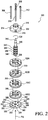
- a new and improved metering gear pump or segment is disclosed and is generally indicated by the reference character 100. More particularly, it is seen that the new and improved metering gear pump or segment 100 comprises an upper or top cap plate 102, an intermediate or central pump plate 104, and a lower or bottom base plate 106.
- the intermediate or central pump plate 104 is provided with a pair of pump gear cavities 108,110 for respectively housing or containing a pair of pump gears 112, 114, and it is to be noted that the axial length, height, or thickness of each one of the pump gears 112,114, as considered in the direction effectively taken along the longitudinal axis A of the gear pump or segment 100, is substantially equal to the axial length, height, or thickness of the intermediate or central pump plate 104 such that the upper extents of the pump gears 112,114 do not project above the upper or top surface portion of the intermediate or central pump plate 104, and in a similar manner, the lower extents of the pump gears 112,114 do not project beneath the lower or undersurface portion of the intermediate or central pump plate 104.
- each one of the pump gears 112,114 is substantially the same as the diametrical extents of the respective pump gear cavities 108,110 such that the outer peripheral edge or surface portions of the pump gears 112,114 are disposed in close proximity to the internal peripheral edge or surface portions of the pump gear cavities 108,110 so as to effectively define sealing interfaces therebetween whereby the liquids being pumped are effectively prevented from passing around the gear perimeters.
- a pair of idler pins 116,118 are disposed within the central openings of the pump gears 112,114 whereby the lower end portions of the idler pins 116,118 are adapted to be disposed within a pair of bushing cavities 120,122 respectively formed within the upper surface portion of the lower or bottom base plate 106, while the upper end portions of the idler pins 116,118 are similarly adapted to be disposed within a pair of bushing cavities, not shown or visible, respectively formed within the undersurface portion of the upper or top cap plate 102.
- a pair of diametrically opposed dowel pins 124,126 are adapted to be inserted through and disposed within the upper or top cap plate 102, the intermediate or central pump plate 104, and the lower or bottom base plate 106 so as to effectively define and maintain the coaxial alignment of the pump gear cavities 108,110, the pump gears 112, 114, the bushing cavities 120,122 defined within the lower or bottom base plate 106, and the bushing cavities, not shown or visible, defined within the upper or top cap plate 102.
- a pair of through-bores 128,130 are therefore accordingly provided within the upper or top cap plate 102 so as to permit the dowel pins 124,126 to pass therethrough, and a pair of through-bores 132,134 are similarly provided within the intermediate or central pump plate 104 so as to likewise pass therethrough, while a pair of through bores 136,138 are also provided within the lower or bottom base plate 106 so as to permit the lower end portions of the dowel pins 124,126 to be seated therein. Due to manufacturing tolerances defined between the dowel pins 124,126 and the through-bores 136,138, the dowel pins 124,126 will be retained within the through-bores 136,138 and will not fall downwardly through or out from the through-bores.
- each one of the idler pins 116, 118 is provided with an axially extending through-bore 140, 142.
- each one of the idler pins 116,118 are provided with small holes or bores 144,146, and similar bores or holes, not shown or visible, are likewise provided upon internal peripheral side wall portions of the pump gears 112,114.
- Small balls or bearing members are adapted to have hemispherical portions thereof disposed within the respective bores or holes of both the pump gears 112,114 and the idler pins 116,118, and in this manner, both of the pair of idler pins 116,118 will rotate with their respective pump gears 112,114 as the pump gears 112,114 are rotatably driven by a suitable drive gear when metering of the fluid is being outputted as will be more fully disclosed and described hereinafter.
- cap screws such as, for example, eight (8) cap screws 148,150,152,154,156,158,160,162 are provided so as to in fact secure the upper or top cap plate 102, the intermediate or central pump plate 104, and the lower or bottom base plate 106 together in a clamping manner such that the intermediate or central pump plate 104 is effectively fixedly secured or sandwiched between the upper or top cap plate 102 and the lower or bottom base plate 106.
- each one of the cap screws 148,150,152,154,156, 158,160,162 passes through through-bores 164,166,168,170,172, 174,176,178 defined within the upper or top cap plate 102, and similarly passes through through-bores 180,182,184,186, 188,190,192,194 defined within the intermediate or central pump plate 104 such that the lower end portions of the cap screws 148,150,152,154,156,158,160,162 can be respectively threadedly engaged within internally threaded through bores 196,198,200,202,204,206,208,210 defined within the lower or bottom base plate 106.
- the through-bores 164,166,168,170, 172,174,176,178, defined within the upper or top cap plate 102 have diametrical extents which are somewhat larger than the diametrical extents of the through-bores 180,182,184,186, 188,190,192,194 defined within the intermediate or central pump plate 104 or the internally threaded blind bores 196, 198,200,202,204,206,208,210 defined within the lower or bottom base plate 106, so as to permit the through-bores 164, 166,168,170,172,174,176,178 defined within the upper or top cap plate 102 to accommodate the relatively large diameter head portions of the cap screws 148,150,152,154,156,158, 160,162, whereas the through-bores 180,182,184,186,188,190, 192,194, defined within the intermediate or central pump plate 104, and the internally threaded blind bores 196,198, 200,202,204, 206,208,210,
- the through-bores 164,166,168,170,172,174,176,178 defined within the up-per or top cap plate 102 are counterbored so as to define ledge portions, not shown or visible, within the upper or top cap plate 102 upon which the relatively large head portions of the cap screws 148,150,152,154,156,158,160, 162 can be seated so as to effectively apply a downward clamping force onto the intermediate or central pump plate 104 and the lower or bottom plate 106 when the lower end threaded portions of the cap screws 148,150,152,154,156,158, 160,162 are threadedly engaged within the internally threaded blind bores 196, 198,200,202,204,206,208,210 defined within the lower or bottom base plate 106.
- the plurality of cap screws 148,150,152,154,156,158,160,162 are arranged in a predetermined, substantially horse-shoe shaped array surrounding the pump gear cavities 108,110 as well as a central through-bore or cavity 212 which is adapted to accommodate a drive gear shaft assembly which will be more fully disclosed and described hereinafter.
- This particular substantially horse-shoe shaped array of the plurality of cap screws 148, 150,152,154,156,158,160,162 is provided so as to effectively ensure that those regions of the undersurface face portion of the intermediate or central pump plate 104, which surround the pump gear cavities 108,110 and the central cavity 212, will be disposed in a substantially tight sealing mode with respect to corresponding regions of the upper surface portion of the lower or bottom base plate 106, and similarly, the aforenoted arrangement of the 148,150,152,154,156,158,160,162 will likewise ensure that those regions of the upper surface face portion of the intermediate or central pump plate 104 which, again, surround the pump gear cavities 108,110 and the central cavity 212, will be disposed in a substantially tight sealing mode with respect to corresponding regions of the undersurface portion of the upper or top cap plate 102, so as to optimally ensure no leakage of the pumped fluid.
- FIGURE 1 With reference continuing to be made to FIGURE 1 , as well as to FIGURE 2 , another important feature characteristic of the metering gear pump or segment 100 as disclosed within FIGURE 1 resides in the provision of a pair of dowel pins 214,216 which are adapted to be fixedly mounted within suitable blind bores, not shown or visible, which are provided within undersurface portions of the lower or bottom base plate 106 so as to project or extend axially downwardly therefrom.
- up-per surface portions of the upper or top cap plate 102 are provided with a plurality of blind bores, such as, for example, four (4) blind bores 218,220,222,224, which are circumferentially spaced in an equiangular manner about the longitudinal axis A of the metering pump or segment 100 so as to be spaced in a quadrant array at 90° intervals with respect to each other.
- upper ones of the metering pumps or segments 100A,100B, 100C, 100D may be fixedly nested at predetermined angular positions with respect to lower adjacent ones of the metering pumps or segments 100A,100B,100C,100D as a result of the dowel pins 214,216, projecting downwardly from a particular upper one of the metering pumps or segments 100A,100B,100C, 100D, being seated within a particular pair of the blind bores 218,220,222,224 defined within the upper surface portions of an adjacent lower one of the metering pumps or segments 100A,100B,100C,100D.
- all of the metering pumps or segments 100A, 100B,100C,100D are substantially identical with respect to each other from a structural point of view, although they may differ from each other from a volumetric value or rating point of view, whereby the metered fluid output volumes of the various metering pumps or segments 100A,100B,100C,100D may be different, and the significance of this feature, as well as the provision of the dowel pins 214,216 and the blind bores 218,220,222,224, upon each one of the metering pumps or segments 100A,100B, 100C,100D, particularly when the plurality of metering pumps or segments 100A,100B,100C,100D are utilized to form the metering pump assembly 300, will be disclosed and described hereinafter.
- the metering pump assembly 300 in addition to comprising the plurality of vertically stacked and nested metering pumps or segments 100A,100B,100C,100D, also comprises an up-per pump seal assembly 302 and a lower pump adaptor plate 304.
- cap screws such as, for example, four (4) cap screws 306,308,310,312, are adapted to be used to fixedly secure the upper pump seal assembly 302, the four metering pumps or segments 100A,100B,100C,100D, and the lower pump adaptor plate 304 together.
- the flanged disk or plate portion of the up-per pump seal assembly 302 is provided with four circumferentially spaced, equiangularly separated counterbored through-bores, only three of which are shown or visible at 314,316, 318, so as to permit the relatively small diameter shank portions of the cap screws 306,308,310,312 to pass therethrough while the relatively large diameter head portions of the cap screws 306,308,310,312 are seated upon shelf portions formed by the counterbored sections of the through-bores 314,316,318 formed within the flanged disk or plate portion of the upper pump seal assembly 302.
- each metering pump or segment 100 is provided with correspondingly arranged through-bores 226,228,230,232
- the intermediate or central pump plate 104 of each metering pump or segment 100 is provided with correspondingly arranged through-bores 234,236,238,240
- the lower or bottom base plate 106 of each metering pump or segment 100 is likewise provided with correspondingly arranged through-bores 242, 244,246,248.
- the lower pump adaptor plate 304 of the metering pump assembly 300 is likewise provided with correspondingly arranged through-bores 320,322,324,326 which are adapted to permit the externally threaded lower end portions of the cap screws 306,308,310,312 to pass therethrough, as can best be seen in FIGURE 3 with respect to cap screws 308, 312 such that the entire metering pump assembly 300 will not only be assembled together, as illustrated within FIGURE 3 , but in addition, can be fixedly mounted upon a suitable support component or surface as a result of the threaded engagement of the externally threaded lower end portions of the cap screws 306,308,310,312 within internally threaded bores provided within the support component.
- the bores 320,322,324,326 defined within the lower pump adaptor plate 304 would not be through-bores but would be internally threaded blind bores in which the lower end portions of the cap screws 306,308,310,312 would be threadedly engaged.
- the upper surface portion of the lower pump adaptor plate 304 of the metering pump assembly 300 is provided with a plurality of blind bores, such as, for example, four (4) blind bores 328,330, 332,334, similar to the plurality of blind bores 218,220, 222,224 provided within each upper or top cap plate 102 of each metering pump or segment 100, so as to accommodate the dowel pins 214,216 which project or extend downwardly from the lowermost metering pump or segment 100D of the metering pump assembly 300.
- a drive shaft assembly 336 is adapted to be coaxially inserted through each one of the metering pumps or segments 100A, 100B,100C,100D such that the lower end portion 338 of the drive shaft assembly 336 is supported upon an axially central portion of the pump adaptor plate 304 while the upper end portion 340 of the drive shaft assembly projects upwardly and outwardly from the metering pump assembly 300, as can best be seen in FIGURE 3 , whereby a suitable rotatable drive force, indicated by the arrow CW denoting the drive in the clockwise direction, generated by means of a suitable drive motor, not shown, can be imparted to the drive shaft assembly 336.
- each metering pump or segment 100 In order to accommodate the axially located drive shaft assembly 336, it is further seen, with reference reverting back to FIGURE 1 , that in addition to the pump plate 104 of each metering pump or segment 100 being provided with its central or axially located through-bore or cavity 212, the upper or top cap plate 102 of each metering pump or segment 100 is similarly provided with a central or axially located through-bore or cavity 250 while, still further, the lower or bottom base plate 106 of each metering pump or segment 100 is likewise provided with a central or axially located through-bore or cavity 252.
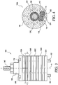
- the drive shaft assembly 336 has a plurality of drive gears, such as, for example, four (4) drive gears 342,344,346,348 fixedly mounted thereon which are adapted to respectively drivingly engage the pump gear 114 of each metering pump or segment 100A,100B,100C,100D as can best be seen in FIGURE 4 which is a cross-sectional view of the metering pump assembly 300 as taken along the lines 4-4 of FIGURE 3 .
- drive gears such as, for example, four (4) drive gears 342,344,346,348 fixedly mounted thereon which are adapted to respectively drivingly engage the pump gear 114 of each metering pump or segment 100A,100B,100C,100D as can best be seen in FIGURE 4 which is a cross-sectional view of the metering pump assembly 300 as taken along the lines 4-4 of FIGURE 3 .
- the fluid to be pumped which may be, for example, hot melt adhesive or some other thermoplastic material
- all of the central through-bores or cavities 252,212, and 250 respectively defined within the lower or bottom base plate 106, the intermediate or central pump plate 104, and the upper or top cap plate 102 will have inner diametrical extents which are slightly larger than the outer diametrical extents of the drive gears 342,344,346,348.
- the fluid will fill an annular area 350 which is defined between the external peripheral region of the drive gear 342 of the drive shaft assembly 336 and the internal peripheral wall portion of the pump plate 104 of the metering pump or segment 100A which defines the central cavity 212.
- This annular region 350 will exist within each metering pump or segment 100A,100B,100C,100D and therefore serves as a common fluid passageway or column by means of which the fluid, being supplied to the metering pump assembly 300 along the fluid inlet supply path FIS , can be supplied to each one of the metering pumps or segments 100A,100B,100C,100D.
- a fluid region 352 is effectively defined at the juncture of pump gears 112,114 and drive gear 342 as shown in FIGURE 4 .
- the fluid supplied to the annular region 350 will therefore effectively be transmitted to, or will supply fluid for, pump gear 114, while the fluid within the fluid region 352 is effectively transmitted to, or will supply fluid for, pump gear 112.
- the pump adaptor plate 304 of the metering pump assembly 300 is provided with a plurality of inlet ports, such as, for example, three circumferentially spaced inlet ports 354 as can best be seen in FIGURE 2 , a central region 355 of the pump adaptor plate 304 being used to support the lower end portion of the drive shaft assembly 336.
- the fluid effectively enters gear space defined within the pump plate 104 of the metering pump or segment 100A, the fluid will effectively fill the area defined between each gear tooth of the pump gears 112,114 and is carried within the cavities 108,110 so as to effectively be introduced into the gear meshing area 254 effectively defined within the pump plate 104 of the metering pump or segment 100A.
- gear meshing area 254 defined within the pump plate 104 of the metering pump or segment 100A, is fluidically connected to an outlet port 256 which is defined within the base plate 106 of each one of the metering pumps or segments 100A, 100B,100C, 100D as illustrated within FIGURE 1 in connection with one of the metering pumps or segments 100.
- each metering pump or segment 100 is provided with a plurality of through-bores or fluid passageways, such as, for example, four through-bores or fluid passageways 258,260,262,264, which are arranged within a circumferentially or angularly spaced array near or adjacent to the inner periphery of the upper or top cap plate 102 such that the through-bores or fluid passageways 258,260,262,264 are effectively disposed within quadrant regions of the upper or top cap plate 102.
- through-bores or fluid passageways such as, for example, four through-bores or fluid passageways 258,260,262,264, which are arranged within a circumferentially or angularly spaced array near or adjacent to the inner periphery of the upper or top cap plate 102 such that the through-bores or fluid passageways 258,260,262,264 are effectively disposed within quadrant regions of the upper or top cap plate 102.
- the intermediate or central pump plate 104 of each metering pump or segment 100 is provided with a plurality of through-bores or fluid passageways, such as, for example, three through-bores or fluid passageways 266,268,270 arranged in a manner similar to that of the through-bores or fluid passageways 258,260,262,264 defined within the upper or top cap plate 102 wherein the through-bores or fluid passageways 266,268,270 of the intermediate or central pump plate 104 are adapted to be coaxially aligned with the through-bores or fluid passageways 258,260,262 of the upper or top cap plate 102 while the fluid passageway 352 of the intermediate or central pump plate 104 is coaxially aligned with the through-bore or fluid passageway 264 of the upper or top cap plate 102.
- through-bores or fluid passageways such as, for example, three through-bores or fluid passageways 266,268,270 arranged in a manner similar to that of the through-bores or fluid passageways 258,260,262,264 defined within
- the lower or bottom base plate 106 is similarly provided with a plurality of through-bores or fluid passageways, such as, for example, three through-bores or fluid passageways 272,274,276, which are arranged in a manner similar to that of the through-bores or fluid passageways 258,260,262,264 defined within the up-per or top cap plate 102, as well as with respect to the through-bores or fluid passageways 266,268,270 defined within the intermediate or central pump plate 104 wherein the through-bores or fluid passageways 272,274,276 of the lower or bottom base plate 106 are coaxially aligned with the through-bores or fluid passageways 266,268,270 defined within the intermediate or central pump plate 104 while the output port 256 of the lower or bottom base plate 106 is coaxially aligned with the fluid passageway 352 of the intermediate or central pump plate 104 as well as with the through-bore or fluid passageway 264 of the upper or top cap plate 102.
- through-bores or fluid passageways such as, for example
- the pump adaptor plate 304 of the metering pump assembly 300 in a manner similar to that of the upper or top cap plate 102 of a particular metering pump or segment 100, is provided with a plurality of through-bores or fluid passageways, such as, for example, four through-bores or fluid passageways 356,358,360,362, which are arranged within a circumferentially or angularly spaced quadrant array.
- the plurality of metering pumps or segments 100A,100B,100C,100D are all substantially identical with respect to each other from a structural point of view. Accordingly, with reference being made to FIGURE 2 , while the metering pump assembly 300 is seen to comprise the vertical stack of metering pumps or segments 100A,100B,100C, 100D, the individual metering pumps or segments may be substituted for one another with no difference in the resulting fluid outputs through output ports 356,358,360,362 if all of the metering pumps or segments 100A,100B,100C,100D have the same metered flow output volumes, values, or ratings, or alternatively, if the metering pumps or segments 100A,100B, 100C,100D have different metered flow output volumes, ratings, or values, different fluid output volumes may be provided to predetermined ones of the ultimate fluid output ports 356,358,360,362.
- a particular metering pump assembly 300 may alternatively comprise a vertical stack of metering pumps or segments 100A,100C,100B,100D, a vertical stack of metering pumps or segments 100A,100D,100B,100C, a vertical stack of metering pumps or segments 100A,100C,100D, 100B, or any one of other similar arrangements so as to provide predetermined volumetric outputs to predetermined ones of the ultimate fluid output ports 356,358,360,362.
- the various fluid output flows routed to the ultimate fluid output ports 356,358,360,362 defined within the pump adaptor plate 304 of the metering pump assembly 300 will now be described.
- the fluid After the fluid input enters the metering pump assembly 300 along the axial inlet flow path FIS , and through the inlet ports 354 of the pump adaptor plate 304, the fluid will be distributed to the various intermediate or central pump plates 104 of the four metering pumps or segments 100A, 100B,100C,100D by means of the aforenoted common fluid passageway or column 350.
- the fluid to be metered and pumped by means of that particular metering pump or segment 100A,100B,100C,100D will be discharged out through the outlet port 256 which is defined within the base plate 106 of that particular one of the metering pumps or segments 100A,100B,100C,100D.
- the metering pump or segment 100D has been mounted within the metering pump assembly 300 such that the outlet port 256 of the base plate 106 of the metering pump segment 100D as illustrated within FIGURE 2 is angularly disposed at a particular angular position with respect to the longitudinal axis of the entire metering pump assembly 300, which is coaxial with the longitudinal axes A of all of the metering pumps or segments 100A,100B,100C, 100D, as well as being coaxial with the fluid inlet supply flow path FIS , whereby the outlet port 256 of the base plate 106 of the metering pump segment 100D will be coaxially aligned with the ultimate fluid output port 362, which is defined within the upper right quadrant of the pump adaptor plate 304 of the metering pump assembly 300 as viewed in FIGURE 2 , then the fluid output 364 from metering pump or segment 100D will be outputted through means of ultimate fluid output port 362.
- the outlet port 256 of the base plate 106 of the metering pump segment 100C as illustrated within FIGURE 2 is angularly disposed at a particular angular position with respect to the longitudinal axis of the entire metering pump assembly 300 such that the angular position of the output port 256 of the base plate 106 of the metering pump or segment 100C is offset 90° in the counterclockwise direction from the angular position of the outlet port 256 of the base plate 106 of the metering pump or segment 100D
- the outlet port 256 of the base plate 106 of the metering pump segment 100C will be coaxially aligned with the ultimate fluid output port 356 defined within the upper left quadrant of the pump adaptor plate 304 of the metering pump assembly 300 as viewed in FIGURE 2 .
- the fluid output from the outlet port 256 of the lower or bottom base plate 106 of the metering pump or segment 100C will flow downwardly through the through-bore or fluid passageway 258 defined within the upper or top cap plate 102 of the metering pump or segment 100D, downwardly through the through-bore or fluid passageway 266 defined within the intermediate or central pump plate 104 of the metering pump or segment 100D, downwardly through the through-bore or fluid passageway 272 defined within the lower or bottom base plate 106 of the metering pump or segment 100D, and will finally be outputted as fluid output flow 366 through means of ultimate fluid output port 356.
- the fluid output from the outlet port 256 of the lower or bottom base plate 106 of the metering pump or segment 100B will flow downwardly through the through-bore or fluid passageway 260 defined within the upper or top cap plate 102 of the metering pump or segment 100C, downwardly through the through-bore or fluid passageway 268 defined within the intermediate or central pump plate 104 of the metering pump or segment 100C, and downwardly through the through-bore or fluid passageway 274 defined within the lower or bottom base plate 106 of the metering pump or segment 100C.
- the fluid flow will be conducted downwardly through the through-bore or fluid passageway 260 defined within the upper or top cap plate 102 of the metering pump or segment 100D, downwardly through the through-bore or fluid passageway 268 defined within the intermediate or central pump plate 104 of the metering pump or segment 100D, downwardly through the through-bore or fluid passageway 274 defined within the lower or bottom base plate 106 of the metering pump or segment 100D, and will be finally outputted through means of ultimate fluid output port 358.
- the fluid output from the outlet port 256 of the lower or bottom base plate 106 of the metering pump or segment 100A will flow downwardly through the through-bore or fluid passageway 262 defined within the upper or top cap plate 102 of the metering pump or segment 100B, downwardly through the through-bore or fluid passageway 270 defined within the intermediate or central pump plate 104 of the metering pump or segment 100B, and downwardly through the through-bore or fluid passageway 276 defined within the lower or bottom base plate 106 of the metering pump or segment 100B such that the fluid flow can then effectively enter the metering pump or segment 100C.
- the fluid flow will be conducted downwardly through the through-bore or fluid passageway 262 de-fined within the upper or top cap plate 102 of the metering pump or segment 100C, downwardly through the through-bore or fluid passageway 270 defined within the intermediate or central pump plate 104 of the metering pump or segment 100C, and downwardly through the through-bore or fluid passageway 276 defined within the lower or bottom base plate 106 of the metering pump or segment 100C.
- the fluid output will be conducted downwardly through the through-bore or fluid passageway 262 defined within the upper or top cap plate 102 of the metering pump or segment 100D, downwardly through the through-bore or fluid passageway 270 defined within the intermediate or central pump plate 104 of the metering pump or segment 100D, and downwardly through the through-bore or fluid passageway 276 defined within the lower or bottom base plate 106 of the metering pump or segment 100D so as to be finally outputted as a fluid flow 370 through means of ultimate fluid output port 360.
- the various metering pumps or segments 100A,100B,100C, 100D can be mounted in accordance with a predetermined order defined within the assembled stack of metering pumps or segments so as to define the assembled pump assembly 300, that is, the various metering pumps or segments can be mounted in the arranged illustrated order ABCD, or alternatively, ACBD,ADBC,ADCB, or the like, but, in addition, the angular position of the various metering pumps or segments 100A,100B, 100C,100D within the stacked array comprising the assembled metering pump assembly 300 can also be altered. This is a significant feature of the metering pumps or segments 100A,100B,100C,100D, as well as for the overall metering pump assembly 300 of the present invention.
- metering pump or segment 100A discharges its metered flow output volume 370 through means of a first ultimate output port 360 disposed in what may be considered a first or lower right quadrant
- metering pump or segment 100B discharges its metered flow output volume 368 through means of a second ultimate output port 358 which is located in what may be considered a second or lower left quadrant
- metering pump or segment 100C discharges its metered flow output volume 366 through means of a third ultimate output port 356 which is located in what may be considered a third or upper left quadrant
- metering pump or segment 100D discharges its metered flow output volume 364 through means of a fourth ultimate output port 362 which is located what may be considered to be a fourth or upper right quadrant
- the various metering pumps or segments 100A,100B,100C,100D can be angularly positioned in alternative modes such that the various metering pumps or segments 100A,100B,100C,100D can have their metered
- different end uses may dictate or require different metered flow output volumes whereby a particular one of the metering pumps or segments 100A,100B,100C,100D may be fluidically connected to a particular one of the ultimate output ports 356,358,360,362 so as to provide the desired or required metered flow output volumes 364,366,368,370.
- metering pumps or segments 100C,100D both comprise pumps which are rated or valued as one cubic centimeter (lcc) pumps, meaning that each pump outputs one cubic centimeter (lcc) of fluid per revolution
- metered flow output volume 364 from metering pump or segment 100D, outputted through means of ultimate output port 362 would be one cubic centimenter(1cc) per revolution of the metering pump or segment 100D, and similarly for metering pump or segment 100C.
- the metering pump or segment 100C is angularly positioned within the metering pump assembly 300 such that its metered flow output volume 366 is coaxially aligned with the fluid output 364 of metering pump or segment 100D such that the resulting metered flow output volume will be outputted through means of ultimate output port 362, then the resulting metered flow output volume outputted through ultimate output port 362 will be two cubic centimeters (2ccs). It is therefore readily apparent that different fluid output volumes can be readily achieved at the different ultimate output ports 356,358,360,362 located within the aforenoted quadrants by selectively programming or arranging the metering pumps or segments 100A,100B,100C,100D within the overall metering pump assembly 300 as has been described.
- metering pumps or segments 100A,100B,100C,100D may differ in size, that is, their metered flow output volume ratings.
- metering pumps or segments 100A,100C may be one cubic centimeter (lcc) pumps
- metering pumps or segments 100B,100D may be two cubic centimeter (2cc) pumps.
- different metered flow output volumes may be achieved at the different ultimate output ports 356,358,360,362 depending upon which metering pump or segment 100A,100B,100C,100D is operatively associated with the particular ultimate output port 356,358,360,362, or alternatively, the fluid outputs of one or more of the metering pumps or segments may be combined as has been described hereinbefore so as to achieve still additional variations in the fluid volumes which are able to be outputted to predetermined ones of the ultimate output ports 356,358,260,362.
- a particular one of the metering pumps or segments 100A,100B,100C,100D having, for example, a particular metered flow output volume rating
- another one of the metering pumps or segments 100A,100B,100C,100D having, for example, a particular but different metered flow output volume rating, and effectively maintained at the same angular position within the overall metering pump assembly 300, such that the metered flow output volume discharged from a particular one of the ultimate output ports 356,358,360,362 is changed or altered as may be desired or required by means of a particularly desired end use.
- one of the metering pumps or segments 100A, 100B,100C,100D may be removed from the metering pump assembly 300 and an entirely new metering pump or segment, similar in structure to the existing metering pumps or segments 100A,100B,100C,100D, but having, for example, a different metered flow output volume rating, may be exchanged for the removed metering pump or segment such that the metered flow output volume discharged from a particular one of the ultimate output ports 356,358,360,362 is changed or altered as may also be desired or required by means of a particularly desired end use.
- a new and improved metering pump or segment and a new and improved metering pump assembly comprising a plurality of the metering pumps or segments, wherein in connection with the individual metering pumps or segments, the drive shaft assembly for driving the pump gears of each metering pump or segment is coaxially aligned with the longitudinal axis of the pump or segment, as is the fluid inlet supply path, whereby only three gears are required to comprise each metering pump or segment.
- the drive shaft assembly and fluid inlet supply path coaxial with the longitudinal axis of the metering pump assembly, but the single drive shaft assembly is utilized to drive all of the metering pumps or segments comprising the metering pump assembly, and the different metering pumps or segments are fluidically connected together by means of a common fluid passageway.
- the different metering pumps or segments comprising the metering assembly can be interchanged with respect to each other so as to permit different metered fluid output volumes to be outputted at different predetermined locations.
- different metering pumps or segments having different output ratings or values, can be exchanged for existing metering pumps or segments within the metering pump assembly and thereby disposed at the predetermined positions within the metering pump assembly so as to achieve the different metered flow output volumes at the predetermined positions.
- different metering pumps or segments can be disposed or arranged such that their fluid output flows will be located at substantially the same predetermined positions within the metering pump assembly whereby the metered fluid output volumes from the various metering pumps or segments can effectively be added together so as to achieve additionally desired metered fluid output volumes which are different from that achieved from any single one metering pump or segment.
Description
- The present invention relates generally to metering pumps, and more particularly to a new and improved metering pump or segment, and to a new and improved metering pump assembly comprising a plurality of the metering pumps or segments, wherein in connection with the individual metering pumps or segments, the drive shaft assembly for driving the pump gears of each metering pump or segment is coaxially aligned with the longitudinal axis of the pump or segment, as is the fluid inlet supply path, whereby only three gears are required to comprise each metering pump or segment, and in connection with the metering pump assembly comprising the plurality of metering pumps or segments, not only is the drive shaft assembly and fluid inlet supply path coaxial with the longitudinal axis of the metering pump assembly, but the single drive shaft assembly is utilized to drive all of the metering pumps or segments comprising the metering pump assembly, and the different metering pumps or segments are fluidically connected together by means of a common fluid passageway. In addition, the different metering pumps or segments comprising the metering assembly can be interchanged with respect to each other so as to permit different metered flow output volumes to be outputted at different predetermined locations. Furthermore, different metering pumps or segments, having different output ratings or values, can be exchanged for existing metering pumps or segments within the metering pump assembly and thereby disposed at the predetermined positions within the metering pump assembly so as to achieve the different metered flow output volumes at the predetermined positions. Lastly, different metering pumps or segments can be disposed or arranged such that their fluid output flows will be located at substantially the same predetermined positions within the metering pump assembly whereby the metered fluid output volumes from the various metering pumps or segments can effectively be added together so as to achieve additionally desired metered fluid output volumes which are different from that achieved from any single one metering pump or segment.
- In some fluid delivery systems, such as, for example, those systems delivering hot melt adhesive or other thermoplastic materials, it is necessary to supply various output devices with predetermined volumes of the fluids. Metering pumps are utilized to in fact provide the fluids in metered amounts as required or dictated by means of their desired or specific end use. The metering pumps are driven by motor drive assemblies which operate the respective pumps at predetermined speeds in order that the metering pumps output the predetermined volumes of the fluid required for the particular use or by the particular output device. However, it is sometimes desired to achieve different metered fluid output volumes in order to provide different metered fluid output volumes to different output devices or for different end uses.
- One known type of metering pump assembly is that disclosed within United States Patent
6,688,498 which is entitled HOT MELT ADHESIVE SUPPLY SYSTEM WITH INDEPENDENT GEAR PUMP ASSEMBLIES and which issued to McGuffey on February 10, 2004. While this metering pump system is quite satisfactory, it is noted that the arrangement does require the supply of the hot melt adhesive into a manifold and the subsequent supply or transmission of the fluid to the metering pump gears by means of a gearing system which comprises four gears. Another known type of metering pump assembly is that disclosed within United States Patent6,422,428 which is entitled SEGMENTED APPLICATOR FOR HOT MELT ADHESIVES OR OTHER THERMOPLAS-TIC MATERIALS and which issued to Allen et al. on July 23, 2002. While this metering pump system is also satisfactory, it is noted that the drive shaft assembly and the fluid input into the metering pump assembly are not coaxially aligned with the longitudinal axis of the metering pump assembly. In addition, the different metering pumps or segments cannot be disposed or arranged such that their fluid output flows will be located at substantially the same predetermined positions within the metering pump assembly whereby the metered fluid output volumes from the various metering pumps or segments can effectively be added together so as to achieve additionally desired metered fluid output volumes which are different from that achieved from any single one metering pump or segment. - A need therefore exists for a new and improved metering pump or segment which is relatively simplified in structure and yet, when incorporated within a metering pump assembly, the individual metering pumps or segments can be driven by means of a single drive shaft assembly, the individual metering pump or segments can be fluidically connected together by means of a common fluid passageway, the individual metering pumps or segments can be interchanged with each other so as to provide different metered fluid output volumes at different predetermined locations, the metering pumps or segments incorporated within the metering pump assembly can be exchanged for other metering pumps or segments so as to provide still yet different metered fluid output volumes, and the metering pumps or segments incorporated within the metering pump assembly can be predeterminedly positioned with respect to each other such that the metered fluid output volumes from the various metering pumps or segments can effectively be added together so as to achieve additional different metered fluid output volumes.
- The foregoing and other objectives are achieved in accordance with the teachings and principles of the present invention through the provision of a new and improved metering pump or segment, and to a new and improved metering pump assembly comprising a plurality of the metering pumps or segments, wherein in connection with the individual metering pumps or segments, the drive shaft assembly for driving the pump gears of each metering pump or segment is coaxially aligned with the longitudinal axis of the pump or segment, as is the fluid inlet supply path, whereby only three gears are required to comprise each metering pump or segment. In connection with the metering pump assembly comprising the plurality of metering pumps or segments, not only is the drive shaft assembly and fluid inlet supply path coaxial with the longitudinal axis of the metering pump assembly, but the single drive shaft assembly is utilized to drive all of the metering pumps or segments comprising the metering pump assembly, and the different metering pumps or segments are fluidically connected together by means of a common fluid passageway.
- In addition, the different metering pumps or segments comprising the metering assembly can be interchanged with respect to each other so as to permit different metered fluid output volumes to be outputted at different predetermined locations. Furthermore, different metering pumps or segments, having different output ratings or values, can be exchanged for existing metering pumps or segments within the metering pump assembly and thereby disposed at the predetermined positions within the metering pump assembly so as to achieve the different metered flow output volumes at the predetermined positions. Lastly, different metering pumps or segments can be disposed or arranged such that their fluid output flows will be located at substantially the same predetermined positions within the metering pump assembly whereby the metered fluid output volumes from the various metering pumps or segments can effectively be added together so as to achieve additionally desired metered fluid output volumes which are different from that achieved from any single one metering pump or segment.
-
US 2,589,528 A discloses a metering pump with a central drive gear and two pump gears. The central drive gear is driven by a shaft which is not coaxially disposed with respect to the fluid inlet supply path of the pump. - The same applies for
US 3,502,033 A where a drive shaft is connected to two parallel driven gears which each enmesh separate gears. The fluid inlet supply path of the pump disclosed in said document is not disposed coaxially with respect to said drive shaft assembly. -
US 2007/248480 A1 discloses a metering pump assembly with pump modules disposed in a serial array. Said pump assembly provides a common fluid passageway as an inlet supply passageway parallel to a drive shaft assembly. On the other side of the drive shaft assembly, which carries several drive gears, an outlet path is located. Since the internal geometry of the whole assembly is asymmetric, the pump modules may only be mounted together in a certain predetermined orientation. - It has to be mentioned that the invention as set forth in claim 11 could be practised by a metering pump assembly wherein said serial array of said plurality of metering pumps comprises a vertically stacked nested array of said plurality of metering pumps.
- It may further comprise four bores respectively defined within equiangularly spaced quadrants defined within said upper cap plate of each one of said plurality of metering pumps; and
- a second pair of diametrically opposed dowel pins projecting downwardly from undersurface portions of each one of said lower base plates of each one of said plurality of metering pumps whereby when a first one of said plurality of metering pumps is disposed above a second one of said plurality of metering pumps disposed within said vertically stacked nested array of said plurality of metering pumps comprising said metering pump assembly, the angular orientation of said first one of said plurality of metering pumps, with respect to said second one of said plurality of metering pumps, disposed beneath said first one of said plurality of metering pumps within said vertically stacked nested array of said plurality of metering pumps comprising said metering pump assembly, and as considered with respect to said longitudinal axis of said metering pump assembly, will be determined as a result of within which two diametrically opposite bores, of said four bores defined within said upper cap plate of said second lower one of said plurality of metering pumps of said metering pump assembly, said second pair of dowel pins of said first upper one of said plurality of metering pumps of said metering pump assembly will be disposed, whereby said first one of said plurality of metering pumps may be angularly oriented with respect to said second one of said plurality of metering pumps in angular increments of 90°.
- Preferably said metering pump assembly comprises an upper pump seal assembly disposed atop the uppermost one of said plurality of metering pumps comprising said metering pump assembly, and a lower pump adaptor plate disposed beneath the lowermost one of said plurality of metering pumps comprising said metering pump assembly.
- This invention may further preferably be practised by said metering pump assembly wherein a metered fluid output port is defined within each one of said pump plates of each one of said metering pumps;
- a plurality of ultimate output ports are defined within quadrants of said lower pump adaptor plate; and
- vertically oriented fluid passages are defined within, and extend through, all of said plurality of metering pumps so as to permit the fluid output from any one of said metered fluid output ports of said plurality of meteriong pumps to be fluidically connected to any one of said plurality of ultimate output ports defined within said lower pump adaptor plate.
- This invention may further preferably be practised by said metering pump assembly wherein multiple metering pumps of said metering pump assembly may be angularly oriented to the same predetermined angular positions with respect to said common longitudinal axis of said metering pump assembly such that the fluid out-puts from said multiple metering pumps may be discharged through the same ultimate output port defined within a par-ticular quadrant of said lower pump adaptor plate of said metering pump assembly whereby fluid volumes from different ones of said plurality of metering pumps may effectively be combined and discharged from predetermined ones of said ultimate output ports defined within said lower pump adaptor plate of said metering pump assembly.
- In case the metering pump assembly comprises an upper pump seal assembly disposed atop the uppermost one of said plurality of metering pumps comprising said metering pump assembly, and a lower pump adaptor plate disposed beneath the lowermost one of said plurality of metering pumps comprising said metering pump assembly, the metering pump assembly may further comprise a second set of fasteners disposed through said up-per pump seal assembly, said plurality of metering pumps, and said lower pump adaptor plate so as to fixedly secure said upper pump seal assembly, said plurality of metering pumps, and said lower pump adaptor plate together and thereby define said metering pump assembly.
- It has also be noted that the invention as set forth in claim 8 could also be practised by a metering pump assembly wherein different metering pumps, having different metered fluid output ratings, can be removably disposed within said metering pump assembly.
- Various other features and attendant advantages of the present invention will be more fully appreciated from the following detailed description when considered in connection with the accompanying drawings in which like reference characters designate like or corresponding parts throughout the several views, and wherein:
-
FIGURE 1 is an exploded view of a new and improved metering pump or segment as constructed in accordance with the principles and teachings of the present invention and showing the operative parts thereof; -
FIGURE 2 is an exploded view of a new and improved metering pump assembly, comprising a plurality of the metering pumps or segments disclosed withinFIGURE 1 , as constructed in accordance with the principles and teachings of the present invention and showing the operative parts thereof; -
FIGURE 3 is a front elevational view of the assembled metering pump assembly disclosed withinFIGURE 2 ; and -
FIGURE 4 is a cross-sectional view of the assembled metering pump assembly as disclosed withinFIGURE 3 and as taken along lines 4-4 ofFIGURE 3 . - Referring now to the drawings, and more particularly to
FIGURE 1 thereof, a new and improved metering gear pump or segment is disclosed and is generally indicated by thereference character 100. More particularly, it is seen that the new and improved metering gear pump orsegment 100 comprises an upper ortop cap plate 102, an intermediate orcentral pump plate 104, and a lower orbottom base plate 106. In connection with the intermediate orcentral pump plate 104, it is seen that the intermediate orcentral pump plate 104 is provided with a pair of pump gear cavities 108,110 for respectively housing or containing a pair ofpump gears segment 100, is substantially equal to the axial length, height, or thickness of the intermediate orcentral pump plate 104 such that the upper extents of the pump gears 112,114 do not project above the upper or top surface portion of the intermediate orcentral pump plate 104, and in a similar manner, the lower extents of the pump gears 112,114 do not project beneath the lower or undersurface portion of the intermediate orcentral pump plate 104. It is also to be noted that the diametrical extents of each one of the pump gears 112,114 is substantially the same as the diametrical extents of the respective pump gear cavities 108,110 such that the outer peripheral edge or surface portions of the pump gears 112,114 are disposed in close proximity to the internal peripheral edge or surface portions of the pump gear cavities 108,110 so as to effectively define sealing interfaces therebetween whereby the liquids being pumped are effectively prevented from passing around the gear perimeters. - In order to maintain the pair of pump gears 112,114 centered within their respective pump gear cavities 108,110, a pair of idler pins 116,118 are disposed within the central openings of the pump gears 112,114 whereby the lower end portions of the idler pins 116,118 are adapted to be disposed within a pair of bushing cavities 120,122 respectively formed within the upper surface portion of the lower or
bottom base plate 106, while the upper end portions of the idler pins 116,118 are similarly adapted to be disposed within a pair of bushing cavities, not shown or visible, respectively formed within the undersurface portion of the upper ortop cap plate 102. In addition, a pair of diametrically opposed dowel pins 124,126 are adapted to be inserted through and disposed within the upper ortop cap plate 102, the intermediate orcentral pump plate 104, and the lower orbottom base plate 106 so as to effectively define and maintain the coaxial alignment of the pump gear cavities 108,110, thepump gears bottom base plate 106, and the bushing cavities, not shown or visible, defined within the upper ortop cap plate 102. A pair of through-bores 128,130 are therefore accordingly provided within the upper ortop cap plate 102 so as to permit the dowel pins 124,126 to pass therethrough, and a pair of through-bores 132,134 are similarly provided within the intermediate orcentral pump plate 104 so as to likewise pass therethrough, while a pair of through bores 136,138 are also provided within the lower orbottom base plate 106 so as to permit the lower end portions of the dowel pins 124,126 to be seated therein. Due to manufacturing tolerances defined between the dowel pins 124,126 and the through-bores 136,138, the dowel pins 124,126 will be retained within the through-bores 136,138 and will not fall downwardly through or out from the through-bores. - In this manner, when the metering pump or
segment 100, comprising the upper ortop cap plate 102, the intermediate orcentral pump plate 104, and the lower orbottom base plate 106 are assembled together, the pump gears 112,114 will be able to rotate freely within the confines of their pump gear cavities 108,110. In connection with the idler pins 116,118, it is additionally noted that each one of the idler pins 116, 118 is provided with an axially extending through-bore 140, 142. Due to the close tolerances defined between the external peripheral surface portions of each one of the idler pins 116,118 and the inner peripheral surface portions of the bushing cavities 120,122 defined within the lower orbottom base plate 106, as well as the close tolerances defined between the external peripheral surface portions of each one of the idler pins 116,118 and the inner peripheral surface portions of the bushing cavities, not shown or visible, defined within the upper ortop cap plate 102, it has been found that the provision of such axially extending through-bores 140,142 within the idler pins 116,118 effectively relieves any "suction" or "vacuum" effect that may develop between the idler pins 116,118 and the bushing cavities as a result of the aforenoted close tolerances. In this manner, it has been found still further that the idler pins 116,118 are able to be more easily inserted and withdrawn from the bushing cavities. Still yet further, it is also seen that outer peripheral side wall portions of each one of the idler pins 116,118 are provided with small holes or bores 144,146, and similar bores or holes, not shown or visible, are likewise provided upon internal peripheral side wall portions of the pump gears 112,114. Small balls or bearing members are adapted to have hemispherical portions thereof disposed within the respective bores or holes of both the pump gears 112,114 and the idler pins 116,118, and in this manner, both of the pair of idler pins 116,118 will rotate with their respective pump gears 112,114 as the pump gears 112,114 are rotatably driven by a suitable drive gear when metering of the fluid is being outputted as will be more fully disclosed and described hereinafter. - With continued reference being made to
FIGURE 1 , and in connection with the assembly of the upper ortop cap plate 102, the intermediate orcentral pump plate 104, and the lower orbottom base plate 106 together so as to in fact form the metering gear pump orsegment 100, it is noted that a plurality of cap screws, such as, for example, eight (8) cap screws 148,150,152,154,156,158,160,162, are provided so as to in fact secure the upper ortop cap plate 102, the intermediate orcentral pump plate 104, and the lower orbottom base plate 106 together in a clamping manner such that the intermediate orcentral pump plate 104 is effectively fixedly secured or sandwiched between the upper ortop cap plate 102 and the lower orbottom base plate 106. More particularly, it is seen that each one of the cap screws 148,150,152,154,156, 158,160,162 passes through through-bores 164,166,168,170,172, 174,176,178 defined within the upper ortop cap plate 102, and similarly passes through through-bores 180,182,184,186, 188,190,192,194 defined within the intermediate orcentral pump plate 104 such that the lower end portions of the cap screws 148,150,152,154,156,158,160,162 can be respectively threadedly engaged within internally threaded through bores 196,198,200,202,204,206,208,210 defined within the lower orbottom base plate 106. - It is noted that the through-bores 164,166,168,170, 172,174,176,178, defined within the upper or
top cap plate 102 have diametrical extents which are somewhat larger than the diametrical extents of the through-bores 180,182,184,186, 188,190,192,194 defined within the intermediate orcentral pump plate 104 or the internally threaded blind bores 196, 198,200,202,204,206,208,210 defined within the lower orbottom base plate 106, so as to permit the through-bores 164, 166,168,170,172,174,176,178 defined within the upper ortop cap plate 102 to accommodate the relatively large diameter head portions of the cap screws 148,150,152,154,156,158, 160,162, whereas the through-bores 180,182,184,186,188,190, 192,194, defined within the intermediate orcentral pump plate 104, and the internally threaded blind bores 196,198, 200,202,204, 206,208,210, defined within the lower orbottom base plate 106, need only accommodate the relatively small diameter shank portions of the cap screws 148,150,152,154, 156,158,160,162. It is also to be noted that the through-bores 164,166,168,170,172,174,176,178 defined within the up-per ortop cap plate 102 are counterbored so as to define ledge portions, not shown or visible, within the upper ortop cap plate 102 upon which the relatively large head portions of the cap screws 148,150,152,154,156,158,160, 162 can be seated so as to effectively apply a downward clamping force onto the intermediate orcentral pump plate 104 and the lower orbottom plate 106 when the lower end threaded portions of the cap screws 148,150,152,154,156,158, 160,162 are threadedly engaged within the internally threaded blind bores 196, 198,200,202,204,206,208,210 defined within the lower orbottom base plate 106. - Still further, it is noted that the plurality of cap screws 148,150,152,154,156,158,160,162 are arranged in a predetermined, substantially horse-shoe shaped array surrounding the pump gear cavities 108,110 as well as a central through-bore or
cavity 212 which is adapted to accommodate a drive gear shaft assembly which will be more fully disclosed and described hereinafter. This particular substantially horse-shoe shaped array of the plurality ofcap screws 148, 150,152,154,156,158,160,162 is provided so as to effectively ensure that those regions of the undersurface face portion of the intermediate orcentral pump plate 104, which surround the pump gear cavities 108,110 and thecentral cavity 212, will be disposed in a substantially tight sealing mode with respect to corresponding regions of the upper surface portion of the lower orbottom base plate 106, and similarly, the aforenoted arrangement of the 148,150,152,154,156,158,160,162 will likewise ensure that those regions of the upper surface face portion of the intermediate orcentral pump plate 104 which, again, surround the pump gear cavities 108,110 and thecentral cavity 212, will be disposed in a substantially tight sealing mode with respect to corresponding regions of the undersurface portion of the upper ortop cap plate 102, so as to optimally ensure no leakage of the pumped fluid. - With reference continuing to be made to
FIGURE 1 , as well as toFIGURE 2 , another important feature characteristic of the metering gear pump orsegment 100 as disclosed withinFIGURE 1 resides in the provision of a pair of dowel pins 214,216 which are adapted to be fixedly mounted within suitable blind bores, not shown or visible, which are provided within undersurface portions of the lower orbottom base plate 106 so as to project or extend axially downwardly therefrom. Correspondingly, it is additionally seen that up-per surface portions of the upper ortop cap plate 102 are provided with a plurality of blind bores, such as, for example, four (4) blind bores 218,220,222,224, which are circumferentially spaced in an equiangular manner about the longitudinal axis A of the metering pump orsegment 100 so as to be spaced in a quadrant array at 90° intervals with respect to each other. Accordingly, when a plurality of metering pumps orsegments FIGURES 2 and3 , so as to form a metering pump assembly, generally indicated by thereference character 300, upper ones of the metering pumps orsegments segments segments segments segments segments segments segments metering pump assembly 300, will be disclosed and described hereinafter. - With reference continuing to be made to
FIGURE 2 , as well as reference being made toFIGURE 3 , and in connection with the formation of themetering pump assembly 300 from the plurality of vertically stacked and nested metering pumps orsegments metering pump assembly 300, in addition to comprising the plurality of vertically stacked and nested metering pumps orsegments pump seal assembly 302 and a lowerpump adaptor plate 304. In addition, a plurality of cap screws, such as, for example, four (4) cap screws 306,308,310,312, are adapted to be used to fixedly secure the upperpump seal assembly 302, the four metering pumps orsegments pump adaptor plate 304 together. More particularly, it is seen that the flanged disk or plate portion of the up-perpump seal assembly 302 is provided with four circumferentially spaced, equiangularly separated counterbored through-bores, only three of which are shown or visible at 314,316, 318, so as to permit the relatively small diameter shank portions of the cap screws 306,308,310,312 to pass therethrough while the relatively large diameter head portions of the cap screws 306,308,310,312 are seated upon shelf portions formed by the counterbored sections of the through-bores 314,316,318 formed within the flanged disk or plate portion of the upperpump seal assembly 302. - Correspondingly, with reference reverting back to
FIGURE 1 , it is seen that the upper ortop cap plate 102 of each metering pump orsegment 100 is provided with correspondingly arranged through-bores 226,228,230,232, the intermediate orcentral pump plate 104 of each metering pump orsegment 100 is provided with correspondingly arranged through-bores 234,236,238,240, and the lower orbottom base plate 106 of each metering pump orsegment 100 is likewise provided with correspondingly arranged through-bores 242, 244,246,248. Lastly, the lowerpump adaptor plate 304 of themetering pump assembly 300 is likewise provided with correspondingly arranged through-bores 320,322,324,326 which are adapted to permit the externally threaded lower end portions of the cap screws 306,308,310,312 to pass therethrough, as can best be seen inFIGURE 3 with respect to capscrews metering pump assembly 300 will not only be assembled together, as illustrated withinFIGURE 3 , but in addition, can be fixedly mounted upon a suitable support component or surface as a result of the threaded engagement of the externally threaded lower end portions of the cap screws 306,308,310,312 within internally threaded bores provided within the support component. Alternatively, if themetering pump assembly 300 is to comprise a stand-alone pump assembly, then the bores 320,322,324,326 defined within the lowerpump adaptor plate 304 would not be through-bores but would be internally threaded blind bores in which the lower end portions of the cap screws 306,308,310,312 would be threadedly engaged. It is also noted that the upper surface portion of the lowerpump adaptor plate 304 of themetering pump assembly 300 is provided with a plurality of blind bores, such as, for example, four (4) blind bores 328,330, 332,334, similar to the plurality of blind bores 218,220, 222,224 provided within each upper ortop cap plate 102 of each metering pump orsegment 100, so as to accommodate the dowel pins 214,216 which project or extend downwardly from the lowermost metering pump orsegment 100D of themetering pump assembly 300. - With reference reverting back to
FIGURE 2 , it is seen that in connection with themetering pump assembly 300, adrive shaft assembly 336 is adapted to be coaxially inserted through each one of the metering pumps orsegments lower end portion 338 of thedrive shaft assembly 336 is supported upon an axially central portion of thepump adaptor plate 304 while theupper end portion 340 of the drive shaft assembly projects upwardly and outwardly from themetering pump assembly 300, as can best be seen inFIGURE 3 , whereby a suitable rotatable drive force, indicated by the arrow CW denoting the drive in the clockwise direction, generated by means of a suitable drive motor, not shown, can be imparted to thedrive shaft assembly 336. In order to accommodate the axially locateddrive shaft assembly 336, it is further seen, with reference reverting back toFIGURE 1 , that in addition to thepump plate 104 of each metering pump orsegment 100 being provided with its central or axially located through-bore orcavity 212, the upper ortop cap plate 102 of each metering pump orsegment 100 is similarly provided with a central or axially located through-bore orcavity 250 while, still further, the lower orbottom base plate 106 of each metering pump orsegment 100 is likewise provided with a central or axially located through-bore orcavity 252. - With reference again being made to
FIGURE 2 , it is further seen that thedrive shaft assembly 336 has a plurality of drive gears, such as, for example, four (4) drive gears 342,344,346,348 fixedly mounted thereon which are adapted to respectively drivingly engage thepump gear 114 of each metering pump orsegment FIGURE 4 which is a cross-sectional view of themetering pump assembly 300 as taken along the lines 4-4 ofFIGURE 3 . Accordingly, due to the clockwise rotation of thedrive shaft assembly 336, thepump gear 114 of each metering pump orsegment pump gear 112 of each metering pump orsegment metering pump assembly 300 in a coaxial manner, with respect to the various metering pumps orsegments drive shaft assembly 336, and along the flow path referenced by means of the arrow FIS inFIGURE 2 denoting the same as the fluid inlet supply, it is noted that all of the central through-bores or cavities 252,212, and 250 respectively defined within the lower orbottom base plate 106, the intermediate orcentral pump plate 104, and the upper ortop cap plate 102 will have inner diametrical extents which are slightly larger than the outer diametrical extents of the drive gears 342,344,346,348. Accordingly, the fluid will fill anannular area 350 which is defined between the external peripheral region of thedrive gear 342 of thedrive shaft assembly 336 and the internal peripheral wall portion of thepump plate 104 of the metering pump orsegment 100A which defines thecentral cavity 212. Thisannular region 350 will exist within each metering pump orsegment metering pump assembly 300 along the fluid inlet supply path FIS, can be supplied to each one of the metering pumps orsegments - In addition, within each metering pump or
segment pump plate 104 of each metering pump orsegment fluid region 352 is effectively defined at the juncture of pump gears 112,114 and drivegear 342 as shown inFIGURE 4 . The fluid supplied to theannular region 350 will therefore effectively be transmitted to, or will supply fluid for,pump gear 114, while the fluid within thefluid region 352 is effectively transmitted to, or will supply fluid for,pump gear 112. In order to in fact permit the fluid inlet supply FIS to enter themetering pump assembly 300 and to flow upwardly through thedrive shaft assembly 336 as just previously described, thepump adaptor plate 304 of themetering pump assembly 300 is provided with a plurality of inlet ports, such as, for example, three circumferentially spacedinlet ports 354 as can best be seen inFIGURE 2 , acentral region 355 of thepump adaptor plate 304 being used to support the lower end portion of thedrive shaft assembly 336. Continuing further with reference still being made toFIGURE 4 , as the fluid effectively enters gear space defined within thepump plate 104 of the metering pump orsegment 100A, the fluid will effectively fill the area defined between each gear tooth of the pump gears 112,114 and is carried within the cavities 108,110 so as to effectively be introduced into thegear meshing area 254 effectively defined within thepump plate 104 of the metering pump orsegment 100A. - It is to be further appreciated that the
gear meshing area 254, defined within thepump plate 104 of the metering pump orsegment 100A, is fluidically connected to anoutlet port 256 which is defined within thebase plate 106 of each one of the metering pumps orsegments FIGURE 1 in connection with one of the metering pumps orsegments 100. Still yet further, it is also seen, as can best be appreciated fromFIGURE 1 , that the upper ortop cap plate 102 of each metering pump orsegment 100 is provided with a plurality of through-bores or fluid passageways, such as, for example, four through-bores or fluid passageways 258,260,262,264, which are arranged within a circumferentially or angularly spaced array near or adjacent to the inner periphery of the upper ortop cap plate 102 such that the through-bores or fluid passageways 258,260,262,264 are effectively disposed within quadrant regions of the upper ortop cap plate 102. - In turn, the intermediate or
central pump plate 104 of each metering pump orsegment 100 is provided with a plurality of through-bores or fluid passageways, such as, for example, three through-bores or fluid passageways 266,268,270 arranged in a manner similar to that of the through-bores or fluid passageways 258,260,262,264 defined within the upper ortop cap plate 102 wherein the through-bores or fluid passageways 266,268,270 of the intermediate orcentral pump plate 104 are adapted to be coaxially aligned with the through-bores or fluid passageways 258,260,262 of the upper ortop cap plate 102 while thefluid passageway 352 of the intermediate orcentral pump plate 104 is coaxially aligned with the through-bore orfluid passageway 264 of the upper ortop cap plate 102. It is lastly noted that the lower orbottom base plate 106 is similarly provided with a plurality of through-bores or fluid passageways, such as, for example, three through-bores or fluid passageways 272,274,276, which are arranged in a manner similar to that of the through-bores or fluid passageways 258,260,262,264 defined within the up-per ortop cap plate 102, as well as with respect to the through-bores or fluid passageways 266,268,270 defined within the intermediate orcentral pump plate 104 wherein the through-bores or fluid passageways 272,274,276 of the lower orbottom base plate 106 are coaxially aligned with the through-bores or fluid passageways 266,268,270 defined within the intermediate orcentral pump plate 104 while theoutput port 256 of the lower orbottom base plate 106 is coaxially aligned with thefluid passageway 352 of the intermediate orcentral pump plate 104 as well as with the through-bore orfluid passageway 264 of the upper ortop cap plate 102. - Lastly, with respect to the overall
metering pump assembly 300, it is noted that thepump adaptor plate 304 of themetering pump assembly 300, in a manner similar to that of the upper ortop cap plate 102 of a particular metering pump orsegment 100, is provided with a plurality of through-bores or fluid passageways, such as, for example, four through-bores or fluid passageways 356,358,360,362, which are arranged within a circumferentially or angularly spaced quadrant array. In this manner, they are adapted to be coaxially aligned with respect to the various aforenoted through-bores or fluid passageways provided within the upper ortop cap plates 102 of the metering pumps orsegments central pump plates 104 of the metering pumps orsegments bottom base plates 106 of the metering pumps orsegments pump adaptor plate 304 of themetering pump assembly 300 serve as ultimate output ports from themetering pump assembly 300 wherein the particular volumetrically metered fluid outputs from such output ports can then be routed wherever desired to downstream output devices or to end use positions or locations. The significance of the aforenoted through-bores or fluid passageway quadrant arrangements, and the resulting fluid outputs from the ultimate output ports 356,358,360,362 defined within thepump adaptor plate 304 of themetering pump assembly 300, will now be disclosed and described. - It will be recalled that the plurality of metering pumps or
segments FIGURE 2 , while themetering pump assembly 300 is seen to comprise the vertical stack of metering pumps orsegments segments segments metering pump assembly 300 may alternatively comprise a vertical stack of metering pumps orsegments segments segments metering pump assembly 300, the various fluid output flows routed to the ultimate fluid output ports 356,358,360,362 defined within thepump adaptor plate 304 of themetering pump assembly 300 will now be described. - After the fluid input enters the
metering pump assembly 300 along the axial inlet flow path FIS, and through theinlet ports 354 of thepump adaptor plate 304, the fluid will be distributed to the various intermediate orcentral pump plates 104 of the four metering pumps orsegments column 350. Once the fluid has reached a particular intermediate orcentral pump plate 104 of a particular metering pump orsegment segment outlet port 256 which is defined within thebase plate 106 of that particular one of the metering pumps orsegments segment 100D has been mounted within themetering pump assembly 300 such that theoutlet port 256 of thebase plate 106 of themetering pump segment 100D as illustrated within FIGURE 2 is angularly disposed at a particular angular position with respect to the longitudinal axis of the entiremetering pump assembly 300, which is coaxial with the longitudinal axes A of all of the metering pumps orsegments outlet port 256 of thebase plate 106 of themetering pump segment 100D will be coaxially aligned with the ultimatefluid output port 362, which is defined within the upper right quadrant of thepump adaptor plate 304 of themetering pump assembly 300 as viewed in FIGURE 2, then thefluid output 364 from metering pump orsegment 100D will be outputted through means of ultimatefluid output port 362. - In a similar manner, if the metering pump or
segment 100C has been mounted within themetering pump assembly 300 such that theoutlet port 256 of thebase plate 106 of themetering pump segment 100C as illustrated withinFIGURE 2 is angularly disposed at a particular angular position with respect to the longitudinal axis of the entiremetering pump assembly 300 such that the angular position of theoutput port 256 of thebase plate 106 of the metering pump orsegment 100C is offset 90° in the counterclockwise direction from the angular position of theoutlet port 256 of thebase plate 106 of the metering pump orsegment 100D, then theoutlet port 256 of thebase plate 106 of themetering pump segment 100C will be coaxially aligned with the ultimatefluid output port 356 defined within the upper left quadrant of thepump adaptor plate 304 of themetering pump assembly 300 as viewed inFIGURE 2 . Accordingly, the fluid output from theoutlet port 256 of the lower orbottom base plate 106 of the metering pump orsegment 100C will flow downwardly through the through-bore orfluid passageway 258 defined within the upper ortop cap plate 102 of the metering pump orsegment 100D, downwardly through the through-bore orfluid passageway 266 defined within the intermediate orcentral pump plate 104 of the metering pump orsegment 100D, downwardly through the through-bore orfluid passageway 272 defined within the lower orbottom base plate 106 of the metering pump orsegment 100D, and will finally be outputted asfluid output flow 366 through means of ultimatefluid output port 356. - Continuing further, and in a similar manner, if the metering pump or
segment 100B has been mounted within themetering pump assembly 300 such thatoutlet port 256 of thebase plate 106 of themetering pump segment 100B as illustrated withinFIGURE 2 is angularly disposed at a particular angular position with respect to the longitudinal axis of the entiremetering pump assembly 300 whereby the angular position of theoutput port 256 of thebase plate 106 of the metering pump orsegment 100B is offset 90° in the counterclockwise direction from the angular position of theoutlet port 256 of thebase plate 106 of the metering pump orsegment 100C, then theoutlet port 256 of thebase plate 106 of themetering pump segment 100B will be coaxially aligned with the ultimatefluid output port 358 which is defined within the lower left quadrant of thepump adaptor plate 304 of themetering pump assembly 300 as viewed inFIGURE 2 . Accordingly, the fluid output from theoutlet port 256 of the lower orbottom base plate 106 of the metering pump orsegment 100B will flow downwardly through the through-bore orfluid passageway 260 defined within the upper ortop cap plate 102 of the metering pump orsegment 100C, downwardly through the through-bore orfluid passageway 268 defined within the intermediate orcentral pump plate 104 of the metering pump orsegment 100C, and downwardly through the through-bore orfluid passageway 274 defined within the lower orbottom base plate 106 of the metering pump orsegment 100C. Yet further, the fluid flow will be conducted downwardly through the through-bore orfluid passageway 260 defined within the upper ortop cap plate 102 of the metering pump orsegment 100D, downwardly through the through-bore orfluid passageway 268 defined within the intermediate orcentral pump plate 104 of the metering pump orsegment 100D, downwardly through the through-bore orfluid passageway 274 defined within the lower orbottom base plate 106 of the metering pump orsegment 100D, and will be finally outputted through means of ultimatefluid output port 358. - Lastly, it will be appreciated that if the metering pump or
segment 100A has been mounted within themetering pump assembly 300 such thatoutlet port 256 of thebase plate 106 of themetering pump segment 100A, as illustrated withinFIGURE 2 , is angularly disposed at a particular angular position with respect to the longitudinal axis of the entiremetering pump assembly 300, whereby the angular position of theoutput port 256 of thebase plate 106 of the metering pump orsegment 100A is offset 90° in the counterclockwise direction from the angular position of theoutlet port 256 of thebase plate 106 of the metering pump orsegment 100B, then theoutlet port 256 of thebase plate 106 of themetering pump segment 100A will be coaxially aligned with the ultimatefluid output port 360 which is defined within the lower right quadrant of thepump adaptor plate 304 of themetering pump assembly 300. Accordingly, the fluid output from theoutlet port 256 of the lower orbottom base plate 106 of the metering pump orsegment 100A will flow downwardly through the through-bore orfluid passageway 262 defined within the upper ortop cap plate 102 of the metering pump orsegment 100B, downwardly through the through-bore orfluid passageway 270 defined within the intermediate orcentral pump plate 104 of the metering pump orsegment 100B, and downwardly through the through-bore orfluid passageway 276 defined within the lower orbottom base plate 106 of the metering pump orsegment 100B such that the fluid flow can then effectively enter the metering pump orsegment 100C. Accordingly, the fluid flow will be conducted downwardly through the through-bore orfluid passageway 262 de-fined within the upper ortop cap plate 102 of the metering pump orsegment 100C, downwardly through the through-bore orfluid passageway 270 defined within the intermediate orcentral pump plate 104 of the metering pump orsegment 100C, and downwardly through the through-bore orfluid passageway 276 defined within the lower orbottom base plate 106 of the metering pump orsegment 100C. Lastly, the fluid output will be conducted downwardly through the through-bore orfluid passageway 262 defined within the upper ortop cap plate 102 of the metering pump orsegment 100D, downwardly through the through-bore orfluid passageway 270 defined within the intermediate orcentral pump plate 104 of the metering pump orsegment 100D, and downwardly through the through-bore orfluid passageway 276 defined within the lower orbottom base plate 106 of the metering pump orsegment 100D so as to be finally outputted as afluid flow 370 through means of ultimatefluid output port 360. - In view of the aforenoted substantially identicality of the various metering pumps or
segments segments pump assembly 300, that is, the various metering pumps or segments can be mounted in the arranged illustrated order ABCD, or alternatively, ACBD,ADBC,ADCB, or the like, but, in addition, the angular position of the various metering pumps orsegments metering pump assembly 300 can also be altered. This is a significant feature of the metering pumps orsegments metering pump assembly 300 of the present invention. - In other words, in lieu of the illustrated angular order wherein metering pump or
segment 100A discharges its meteredflow output volume 370 through means of a firstultimate output port 360 disposed in what may be considered a first or lower right quadrant, metering pump orsegment 100B discharges its meteredflow output volume 368 through means of a secondultimate output port 358 which is located in what may be considered a second or lower left quadrant, metering pump orsegment 100C discharges its meteredflow output volume 366 through means of a thirdultimate output port 356 which is located in what may be considered a third or upper left quadrant, and metering pump orsegment 100D discharges its meteredflow output volume 364 through means of a fourthultimate output port 362 which is located what may be considered to be a fourth or upper right quadrant, the various metering pumps orsegments segments segments - Continuing along these lines, it is to be appreciated that by mounting the different metering pumps or segments at predetermined angular positions, other than those specifically illustrated within
FIGURE 2 , we may achieve different fluid output volumes as desired or required. For example, if metering pump orsegment 100C was to be angularly rotated from its angular disposition illustrated within FIGURE 2 to a different angular disposition such that its meteredoutput flow volume 366 would be coaxially aligned withultimate output port 362 in lieu of being coaxially aligned withultimate output port 356, the metered flow output volume of the outputs from metering pumps orsegments segments flow output volume 364 from metering pump orsegment 100D, outputted through means ofultimate output port 362, would be one cubic centimenter(1cc) per revolution of the metering pump orsegment 100D, and similarly for metering pump orsegment 100C. However, if the metering pump orsegment 100C is angularly positioned within themetering pump assembly 300 such that its meteredflow output volume 366 is coaxially aligned with thefluid output 364 of metering pump orsegment 100D such that the resulting metered flow output volume will be outputted through means ofultimate output port 362, then the resulting metered flow output volume outputted throughultimate output port 362 will be two cubic centimeters (2ccs). It is therefore readily apparent that different fluid output volumes can be readily achieved at the different ultimate output ports 356,358,360,362 located within the aforenoted quadrants by selectively programming or arranging the metering pumps orsegments metering pump assembly 300 as has been described. It is also to be readily appreciated that the different metering pumps orsegments segments segments segment - Still yet further, a particular one of the metering pumps or
segments segments metering pump assembly 300, such that the metered flow output volume discharged from a particular one of the ultimate output ports 356,358,360,362 is changed or altered as may be desired or required by means of a particularly desired end use. Lastly, one of the metering pumps orsegments metering pump assembly 300 and an entirely new metering pump or segment, similar in structure to the existing metering pumps orsegments - Thus, it may be seen that in accordance with the principles and teachings of the present invention, there has been disclosed a new and improved metering pump or segment, and a new and improved metering pump assembly comprising a plurality of the metering pumps or segments, wherein in connection with the individual metering pumps or segments, the drive shaft assembly for driving the pump gears of each metering pump or segment is coaxially aligned with the longitudinal axis of the pump or segment, as is the fluid inlet supply path, whereby only three gears are required to comprise each metering pump or segment. In connection with the metering pump assembly comprising the plurality of metering pumps or segments, not only is the drive shaft assembly and fluid inlet supply path coaxial with the longitudinal axis of the metering pump assembly, but the single drive shaft assembly is utilized to drive all of the metering pumps or segments comprising the metering pump assembly, and the different metering pumps or segments are fluidically connected together by means of a common fluid passageway. In addition, the different metering pumps or segments comprising the metering assembly can be interchanged with respect to each other so as to permit different metered fluid output volumes to be outputted at different predetermined locations. Furthermore, different metering pumps or segments, having different output ratings or values, can be exchanged for existing metering pumps or segments within the metering pump assembly and thereby disposed at the predetermined positions within the metering pump assembly so as to achieve the different metered flow output volumes at the predetermined positions. Lastly, different metering pumps or segments can be disposed or arranged such that their fluid output flows will be located at substantially the same predetermined positions within the metering pump assembly whereby the metered fluid output volumes from the various metering pumps or segments can effectively be added together so as to achieve additionally desired metered fluid output volumes which are different from that achieved from any single one metering pump or segment.
- Obviously, many variations and modifications of thepresent invention are possible in light of the above teachings. It is therefore to be understood that within the scope of the appended claims, the present invention may be practiced otherwise than as specifically described herein.
Claims (15)
- A metering pump (100), comprising:a pump plate (104) defined around an axis (A) and having a central cavity (212) defined therein;a drive shaft assembly (336) disposed coaxially with respect to said axis (A) of said pump plate (104), extending through said central cavity (212) defined within said pump plate (104), and having a drive gear (342) mounted upon said drive shaft assembly (336) so as to be disposed within said pump plate (104);at least one pump gear (112, 114) disposed within said pump plate (104) and engaged with said drive gear (342) so as to be driven by said drive gear; anda fluid inlet supply path disposed coaxially with respect to said drive shaft assembly (336) and said pump plate (104) for supplying a fluid into said metering pump (100) such that a metered amount of the fluid can be metered as an output fluid flow (364, 365, 366, 367, 368, 369, 370) from said metering pump (100).
- The metering pump (100) as set forth in Claim 1, wherein:said at least one pump gear comprises a pair of pump gears (112, 114) wherein a first one (114) of said pair of pump gears is meshingly engaged with said drive gear (342) of said drive shaft assembly (335), and a second one of said pair of pump gears (112) is meshingly engaged with said first one (114) of said pair of pump gears so as to pump the metered amount of fluid out from said metering pump (100).
- The metering pump (100) as set forth in Claim 2, wherein:said metering pump (100) comprises a sandwich construction comprising an upper cap plate (102), a lower base plate (106), and said pump plate (104) interposed between said upper cap plate (102) and said lower base plate (106) and having a pair of cavities (108, 110) defined therein for accommodating said pair of pump gears (112, 114).
- The metering pump (100) as set forth in Claim 3, further wherein:each one of said pair of pump gears (112, 114) has an annular configuration with central openings defined therein; anda pair of idler pins (116, 118) are respectively disposed within said central openings of said pair of pump gears (112, 114), with opposite end portions of said pair of idler pins (116, 118) respectively disposed within bores (120, 122) defined within said upper cap plate (102) and said lower base plate (106), so as to maintain said pair of pump gears (112, 114) centrally located within said pair of cavities (108, 110) defined within said pump plate (104).
- The metering pump (100) as set forth in Claim 4, further comprising:a pair of dowel pins (124, 126) disposed through said upper cap plate (102), said lower base plate (106), and said pump plate (104) interposed between said upper cap plate (102) and said lower base plate (106) for properly angularly aligning said upper cap plate (102), said lower base plate (106), and said pump plate (104), interposed between said upper cap plate and said lower base plate, with respect to each other so as to permit said pair of idler pins (116, 118) to be properly seated within said upper cap plate (102) and said lower base plate (106).
- The metering pump (100) as set forth in Claim 3, further comprising:a plurality of fasteners (148, 149, 150, 151, 152, 153, 154, 155, 156, 157, 158, 159, 160, 161, 162) disposed through said upper cap plate (102), said pump plate (104) interposed between said upper cap plate and said lower base plate, and said lower base plate (106), for fixedly securing said upper cap plate (102), said pump plate (104) interposed between said upper cap plate and said lower base plate, and said lower base plate (106) together so as to define said sandwich construction of said metering pump (100).
- The metering pump as set forth in Claim 6, wherein:said plurality of fasteners (148, 149, 150, 151, 152, 153, 154, 155, 156, 157, 158, 159, 160, 161, 162) are disposed within a substantially horse-shoe shaped array so as to surround said central cavity (212) defined within said pump plate (104) for accommodating said drive gear (342) and said drive shaft assembly (336), and said pair of cavities (108, 110) for accommodating said pair of pump gears (112, 114), so as to ensure surface-to-surface contact between said pump plate (104) and said upper cap plate (102), and between said pump plate (104) and said lower base plate (106), in order to assuredly prevent leakage of fluid out from said metering pump (100).
- A metering pump assembly (300), comprising:a plurality of metering pumps (100A, 100B, 100C, 100D) disposed within a serial array wherein each metering pump (100A, 100B, 100C, 100D) is disposed coaxially around a common longitudinal axis (A) of said metering pump assembly (300) and wherein each metering pump (100A, 100B, 100C, 100D) comprises at least one pump gear (112, 114);a drive shaft assembly (336) disposed coaxially with respect to said common longitudinal axis (A) of said plurality of metering pumps (100A, 100B, 100C, 100D), wherein said drive shaft assembly (336) has a plurality of drive gears (342, 343, 344, 345, 346, 347, 348) mounted thereon for respective engagement with said at least one pump gear (112, 113, 114) of each one of said plurality of metering pumps (100A, 100B, 100C, 100D) so as to drive said at least one pump gear (112, 114) of each one of said plurality of metering pumps; anda fluid inlet supply port (354) disposed coaxially with respect to said drive shaft assembly (336) and said common longitudinal axis (A) of said plurality of metering pumps (100A, 100B, 100C, 100D) for supplying a fluid into said metering pump assembly (300) whereby the fluid can be supplied to each one of said plurality of metering pumps (100A, 100B, 100C, 100D) by means of a common fluid passageway (350) disposed coaxially with respect to said drive shaft assembly (336), such that a metered amount of the fluid can be metered as an output fluid flow from each one of said plurality of metering pumps (100A, 100B, 100C, 100D) of said metering pump assembly (300).
- The metering pump assembly (300) as set forth in Claim 8, wherein:said fluid passageway being a common fluid inlet supply passageway (350) that is defined internally within said metering pump assembly (300) such that incoming fluid is distributed from said fluid inlet supply port (354) to each one of said plurality of metering pumps (100A, 100B, 100C, 100D) comprising said metering pump assembly (300).
- The metering pump assembly (300) as set forth in Claim 8, wherein:said at least one pump gear (112, 114) disposed within each one of said plurality of metering pumps (100A, 100B, 100C, 100D) comprises a pair of pump gears (112, 114) wherein a first one (114) of said pair of pump gears is meshingly engaged with a respective one of said plurality of drive gears (342, 343, 344, 345, 346, 347, 348) disposed upon said drive shaft assembly (336), and a second one (116) of said pair of pump gears is meshingly engaged with said first one (114) of said pair of pump gears so as to pump the metered amount of fluid out from said metering pump (100A, 100B, 100C, 100D).
- The metering pump assembly (300) as set forth in Claim 10, wherein:each one of said plurality of metering pumps (100A, 100B, 100C, 100D) comprises a sandwich construction comprising an upper cap plate (102), a lower base plate (106), and a pump plate (104) interposed between said upper cap plate and said lower base plate and having a pair of cavities (108, 110) defined therein for accommodating said pair of pump gears (112, 114).
- The metering pump assembly (300) as set forth in Claim 11, further wherein:each one of said pair of pump gears (112, 114) has an annular configuration with central openings defined therein; anda pair of idler pins (116, 118) are respectively disposed within said central openings of said pair of pump gears ((112, 114), with opposite end portions of said pair of idler pins (116, 118) respectively disposed within bores (120, 122) defined within said upper cap plate (102) and said lower base plate (106), so as to maintain said pair of pump gears (112, 114) centrally located within said pair of cavities (108, 110) defined within said pump plate (104).
- The metering pump assembly (300) as set forth in Claim 12, further comprising:a first pair of dowel pins (124, 126) disposed through said upper cap plate (102), said lower base plate (106), and said pump plate (104) interposed between said upper cap plate (102) and said lower base plate (106) for properly angularly aligning said upper cap plate (102), said lower base plate (106), and said pump plate (104), interposed between said upper cap plate and said lower base plate, with respect to each other so as to permit said pair of idler pins (116, 118) to be properly seated within said upper cap plate (102) and said lower base plate (106).
- The metering pump assembly (300) as set forth in Claim 11, further comprising:a first set of fasteners (148, 149, 150, 151, 152, 153, 154, 155, 156, 157, 158, 159, 160, 161, 162) disposed through said upper cap plate (102), said pump plate (104) interposed between said upper cap plate and said lower base plate (106), and said lower base plate (106), for fixedly securing said upper cap plate (102), said pump plate (104) interposed between said upper cap plate and said lower base plate, and said lower base plate (106) together so as to define said sandwich construction of each one of said plurality of metering pumps (100A, 100B, 100C, 100D).
- The metering pump assembly (300) as set forth in Claim 14, wherein:said first set of fasteners (148, 149, 150, 151, 152, 153, 154, 155, 156, 157, 158, 159, 160, 161, 162) are disposed within a substantially horse-shoe shaped array so as to surround a central cavity (212) defined within each one of said pump plates (100A, 100B, 100C, 100D) for accommodating said drive gear (342) and said drive shaft assembly (336), and said pair of cavities (108, 110) for accommodating said pair of pump gears (112, 114), so as to ensure surface-to-surface contact between said pump plate (104) and said upper cap plate (102), and between said pump plate (104) and said lower base plate (106), so as to assuredly seal said upper cap plate (102) with respect to said pump plate (104), and said pump plate (104) with respect to said lower base plate (106), in order to effectively prevent leakage of fluid out from any one of said plurality of metering pumps (100A, 100B, 100C, 100D).
Applications Claiming Priority (2)
| Application Number | Priority Date | Filing Date | Title |
|---|---|---|---|
| US12/801,027 US8944792B2 (en) | 2010-05-18 | 2010-05-18 | Metering gear pump or segment, and metering gear pump assembly comprising a plurality of metering gear pumps or segments |
| PCT/US2011/000564 WO2011146099A2 (en) | 2010-05-18 | 2011-03-30 | Metering pump or segment, and metering pump assembly comprising a plurality of metering pumps or segments |
Publications (2)
| Publication Number | Publication Date |
|---|---|
| EP2572076A2 EP2572076A2 (en) | 2013-03-27 |
| EP2572076B1 true EP2572076B1 (en) | 2017-03-15 |
Family
ID=44120883
Family Applications (1)
| Application Number | Title | Priority Date | Filing Date |
|---|---|---|---|
| EP11714869.2A Active EP2572076B1 (en) | 2010-05-18 | 2011-03-30 | Metering pump or segment, and metering pump assembly comprising a plurality of metering pumps or segments |
Country Status (7)
| Country | Link |
|---|---|
| US (1) | US8944792B2 (en) |
| EP (1) | EP2572076B1 (en) |
| JP (1) | JP5727595B2 (en) |
| CN (1) | CN103249951B (en) |
| BR (1) | BR112012029174B1 (en) |
| CA (1) | CA2801976C (en) |
| WO (1) | WO2011146099A2 (en) |
Families Citing this family (8)
| Publication number | Priority date | Publication date | Assignee | Title |
|---|---|---|---|---|
| JP6680786B2 (en) * | 2015-01-08 | 2020-04-15 | セコ・エッセ・ピ・アSeko S.P.A. | Peristaltic pumps, especially peristaltic dosing pumps |
| AU201711337S (en) * | 2016-09-08 | 2017-03-29 | Battlemax Pty Ltd | Adaptor Plate |
| AU201711335S (en) * | 2016-09-08 | 2017-03-29 | Battlemax Pty Ltd | Suction Cover |
| CN110249089B (en) * | 2017-01-12 | 2022-03-15 | 欧瑞康纺织有限及两合公司 | Device for wetting a plurality of threads and metering pump for such a device |
| USD862539S1 (en) * | 2017-12-04 | 2019-10-08 | Liqua-Tech Corporation | Register gear adapter plate |
| USD851693S1 (en) * | 2017-12-04 | 2019-06-18 | Liqua-Tech Corporation | Register gear adapter plate |
| USD851144S1 (en) * | 2017-12-04 | 2019-06-11 | Liqua-Tech Corporation | Register gear adapter plate |
| JP7056409B2 (en) * | 2018-06-28 | 2022-04-19 | いすゞ自動車株式会社 | Gear device |
Family Cites Families (22)
| Publication number | Priority date | Publication date | Assignee | Title |
|---|---|---|---|---|
| US2362922A (en) * | 1942-10-16 | 1944-11-14 | Stewart Warner Corp | Rotary pump |
| US2589528A (en) * | 1948-03-13 | 1952-03-18 | Indian Sales Corp | Low capacity gear pump |
| US2533320A (en) * | 1949-01-04 | 1950-12-12 | Du Pont | Rotary gear-type metering pump |
| US3179382A (en) * | 1963-03-01 | 1965-04-20 | Norton Knedlik | Blending pump |
| US3266430A (en) * | 1964-03-30 | 1966-08-16 | Monsanto Co | Pump mixer |
| GB1252746A (en) * | 1967-12-23 | 1971-11-10 | ||
| US3601514A (en) * | 1969-07-23 | 1971-08-24 | Kermit J Afner | Rotary machine |
| US3869224A (en) * | 1972-12-26 | 1975-03-04 | Glen E Brinkman | Rotary gear device to provide pulsating flow |
| US4195480A (en) * | 1978-12-26 | 1980-04-01 | Caterpillar Tractor Co. | Manifolded multiple hydraulic pump structure |
| CH649133A5 (en) * | 1980-10-29 | 1985-04-30 | Glyco Antriebstechnik Gmbh | GEAR PUMP ARRANGEMENT. |
| GB9221624D0 (en) * | 1992-10-15 | 1992-11-25 | Kodak Ltd | Fluid flow divider |
| DE59404257D1 (en) * | 1993-02-18 | 1997-11-13 | Barmag Barmer Maschf | SPINNING MACHINE FOR THERMOPLASTIC THREADS |
| US5829647A (en) * | 1996-07-23 | 1998-11-03 | Nordson Corporation | Metering gearhead dispensing apparatus having selectively positionable gear pumps |
| US5755566A (en) * | 1996-08-23 | 1998-05-26 | Kalish Canada Inc. | Self-driving fluid pump |
| US6422428B1 (en) * | 1998-04-20 | 2002-07-23 | Nordson Corporation | Segmented applicator for hot melt adhesives or other thermoplastic materials |
| US6296463B1 (en) * | 1998-04-20 | 2001-10-02 | Nordson Corporation | Segmented metering die for hot melt adhesives or other polymer melts |
| US6171089B1 (en) * | 1998-05-12 | 2001-01-09 | Parker-Hannifin Corporation | External gear pump with drive gear seal |
| TW470789B (en) * | 1998-08-29 | 2002-01-01 | Barmag Barmer Maschf | Apparatus for mixing and advancing a polymer melt |
| US6688498B1 (en) * | 2002-12-12 | 2004-02-10 | Illinois Tool Works Inc. | Hot melt adhesive supply system with independent gear pump assemblies |
| US20070248480A1 (en) * | 2006-04-20 | 2007-10-25 | Viking Pump, Inc. | Multiple Section External Gear Pump With the Internal Manifold |
| US20080023489A1 (en) * | 2006-07-31 | 2008-01-31 | Illinois Tool Works Inc. | Remote metering station and applicator heads interconnected by means of relatively short hoses with universal connectors |
| FI120985B (en) * | 2008-02-07 | 2010-05-31 | Pekka Leskinen | Device for evenly distributing a flow to two or more objects |
-
2010
- 2010-05-18 US US12/801,027 patent/US8944792B2/en active Active
-
2011
- 2011-03-30 BR BR112012029174-2A patent/BR112012029174B1/en active IP Right Grant
- 2011-03-30 EP EP11714869.2A patent/EP2572076B1/en active Active
- 2011-03-30 CN CN201180035516.4A patent/CN103249951B/en active Active
- 2011-03-30 WO PCT/US2011/000564 patent/WO2011146099A2/en active Application Filing
- 2011-03-30 JP JP2013511140A patent/JP5727595B2/en active Active
- 2011-03-30 CA CA2801976A patent/CA2801976C/en active Active
Non-Patent Citations (1)
| Title |
|---|
| None * |
Also Published As
| Publication number | Publication date |
|---|---|
| CA2801976A1 (en) | 2011-11-24 |
| WO2011146099A3 (en) | 2013-03-21 |
| BR112012029174A2 (en) | 2017-07-18 |
| JP2013528256A (en) | 2013-07-08 |
| US20110286872A1 (en) | 2011-11-24 |
| US8944792B2 (en) | 2015-02-03 |
| CN103249951B (en) | 2016-06-08 |
| EP2572076A2 (en) | 2013-03-27 |
| JP5727595B2 (en) | 2015-06-03 |
| BR112012029174B1 (en) | 2021-01-26 |
| CN103249951A (en) | 2013-08-14 |
| WO2011146099A2 (en) | 2011-11-24 |
| CA2801976C (en) | 2015-02-10 |
Similar Documents
| Publication | Publication Date | Title |
|---|---|---|
| EP2572076B1 (en) | Metering pump or segment, and metering pump assembly comprising a plurality of metering pumps or segments | |
| EP2587063B1 (en) | Metering gear pump with integral flow indicator | |
| EP1429029B1 (en) | Hot melt adhesive dispensing applicator assembly with independent gear pump assemblies | |
| US7997853B2 (en) | Rotary pressure transfer device with improved flow | |
| US10464098B2 (en) | Remote metering station | |
| JP2019529088A5 (en) | ||
| EP1937974B1 (en) | Remote hot melt adhesive metering station | |
| EP1937975B1 (en) | Hot melt adhesive metering pump assembly with integral reservoir tank | |
| DE102011051486B4 (en) | Pump arrangement with micropump and bearing element | |
| JPH1082374A (en) | Measuring gear head discharge device | |
| CN111097082A (en) | Conveying metering device and infusion device | |
| CN102301210A (en) | A Rotary Metering Device And System | |
| JP3691761B2 (en) | Movable airfoil rotation device | |
| CN216950840U (en) | Small flow liquid pump | |
| JP6437298B2 (en) | Tube pump | |
| GB2468876A (en) | Radial inlet and outlet externally meshing fluid machine and timing gearing | |
| GB2473341A (en) | Alternately driving gear set for a rotary mechanism |
Legal Events
| Date | Code | Title | Description |
|---|---|---|---|
| PUAI | Public reference made under article 153(3) epc to a published international application that has entered the european phase |
Free format text: ORIGINAL CODE: 0009012 |
|
| 17P | Request for examination filed |
Effective date: 20121113 |
|
| AK | Designated contracting states |
Kind code of ref document: A2 Designated state(s): AL AT BE BG CH CY CZ DE DK EE ES FI FR GB GR HR HU IE IS IT LI LT LU LV MC MK MT NL NO PL PT RO RS SE SI SK SM TR |
|
| R17D | Deferred search report published (corrected) |
Effective date: 20130321 |
|
| DAX | Request for extension of the european patent (deleted) | ||
| RAP1 | Party data changed (applicant data changed or rights of an application transferred) |
Owner name: MCGUFFEY, GRANT Owner name: ILLINOIS TOOL WORKS INC. |
|
| GRAP | Despatch of communication of intention to grant a patent |
Free format text: ORIGINAL CODE: EPIDOSNIGR1 |
|
| INTG | Intention to grant announced |
Effective date: 20161115 |
|
| GRAS | Grant fee paid |
Free format text: ORIGINAL CODE: EPIDOSNIGR3 |
|
| GRAA | (expected) grant |
Free format text: ORIGINAL CODE: 0009210 |
|
| AK | Designated contracting states |
Kind code of ref document: B1 Designated state(s): AL AT BE BG CH CY CZ DE DK EE ES FI FR GB GR HR HU IE IS IT LI LT LU LV MC MK MT NL NO PL PT RO RS SE SI SK SM TR |
|
| REG | Reference to a national code |
Ref country code: CH Ref legal event code: EP Ref country code: GB Ref legal event code: FG4D |
|
| REG | Reference to a national code |
Ref country code: IE Ref legal event code: FG4D |
|
| REG | Reference to a national code |
Ref country code: AT Ref legal event code: REF Ref document number: 875802 Country of ref document: AT Kind code of ref document: T Effective date: 20170415 |
|
| REG | Reference to a national code |
Ref country code: DE Ref legal event code: R096 Ref document number: 602011035936 Country of ref document: DE |
|
| REG | Reference to a national code |
Ref country code: NL Ref legal event code: MP Effective date: 20170315 |
|
| REG | Reference to a national code |
Ref country code: LT Ref legal event code: MG4D |
|
| PG25 | Lapsed in a contracting state [announced via postgrant information from national office to epo] |
Ref country code: GR Free format text: LAPSE BECAUSE OF FAILURE TO SUBMIT A TRANSLATION OF THE DESCRIPTION OR TO PAY THE FEE WITHIN THE PRESCRIBED TIME-LIMIT Effective date: 20170616 Ref country code: HR Free format text: LAPSE BECAUSE OF FAILURE TO SUBMIT A TRANSLATION OF THE DESCRIPTION OR TO PAY THE FEE WITHIN THE PRESCRIBED TIME-LIMIT Effective date: 20170315 Ref country code: FI Free format text: LAPSE BECAUSE OF FAILURE TO SUBMIT A TRANSLATION OF THE DESCRIPTION OR TO PAY THE FEE WITHIN THE PRESCRIBED TIME-LIMIT Effective date: 20170315 Ref country code: LT Free format text: LAPSE BECAUSE OF FAILURE TO SUBMIT A TRANSLATION OF THE DESCRIPTION OR TO PAY THE FEE WITHIN THE PRESCRIBED TIME-LIMIT Effective date: 20170315 Ref country code: NO Free format text: LAPSE BECAUSE OF FAILURE TO SUBMIT A TRANSLATION OF THE DESCRIPTION OR TO PAY THE FEE WITHIN THE PRESCRIBED TIME-LIMIT Effective date: 20170615 |
|
| REG | Reference to a national code |
Ref country code: AT Ref legal event code: MK05 Ref document number: 875802 Country of ref document: AT Kind code of ref document: T Effective date: 20170315 |
|
| PG25 | Lapsed in a contracting state [announced via postgrant information from national office to epo] |
Ref country code: LV Free format text: LAPSE BECAUSE OF FAILURE TO SUBMIT A TRANSLATION OF THE DESCRIPTION OR TO PAY THE FEE WITHIN THE PRESCRIBED TIME-LIMIT Effective date: 20170315 Ref country code: SE Free format text: LAPSE BECAUSE OF FAILURE TO SUBMIT A TRANSLATION OF THE DESCRIPTION OR TO PAY THE FEE WITHIN THE PRESCRIBED TIME-LIMIT Effective date: 20170315 Ref country code: RS Free format text: LAPSE BECAUSE OF FAILURE TO SUBMIT A TRANSLATION OF THE DESCRIPTION OR TO PAY THE FEE WITHIN THE PRESCRIBED TIME-LIMIT Effective date: 20170315 Ref country code: BG Free format text: LAPSE BECAUSE OF FAILURE TO SUBMIT A TRANSLATION OF THE DESCRIPTION OR TO PAY THE FEE WITHIN THE PRESCRIBED TIME-LIMIT Effective date: 20170615 |
|
| PG25 | Lapsed in a contracting state [announced via postgrant information from national office to epo] |
Ref country code: NL Free format text: LAPSE BECAUSE OF FAILURE TO SUBMIT A TRANSLATION OF THE DESCRIPTION OR TO PAY THE FEE WITHIN THE PRESCRIBED TIME-LIMIT Effective date: 20170315 |
|
| PG25 | Lapsed in a contracting state [announced via postgrant information from national office to epo] |
Ref country code: CZ Free format text: LAPSE BECAUSE OF FAILURE TO SUBMIT A TRANSLATION OF THE DESCRIPTION OR TO PAY THE FEE WITHIN THE PRESCRIBED TIME-LIMIT Effective date: 20170315 Ref country code: EE Free format text: LAPSE BECAUSE OF FAILURE TO SUBMIT A TRANSLATION OF THE DESCRIPTION OR TO PAY THE FEE WITHIN THE PRESCRIBED TIME-LIMIT Effective date: 20170315 Ref country code: ES Free format text: LAPSE BECAUSE OF FAILURE TO SUBMIT A TRANSLATION OF THE DESCRIPTION OR TO PAY THE FEE WITHIN THE PRESCRIBED TIME-LIMIT Effective date: 20170315 Ref country code: RO Free format text: LAPSE BECAUSE OF FAILURE TO SUBMIT A TRANSLATION OF THE DESCRIPTION OR TO PAY THE FEE WITHIN THE PRESCRIBED TIME-LIMIT Effective date: 20170315 Ref country code: AT Free format text: LAPSE BECAUSE OF FAILURE TO SUBMIT A TRANSLATION OF THE DESCRIPTION OR TO PAY THE FEE WITHIN THE PRESCRIBED TIME-LIMIT Effective date: 20170315 Ref country code: SK Free format text: LAPSE BECAUSE OF FAILURE TO SUBMIT A TRANSLATION OF THE DESCRIPTION OR TO PAY THE FEE WITHIN THE PRESCRIBED TIME-LIMIT Effective date: 20170315 |
|
| REG | Reference to a national code |
Ref country code: CH Ref legal event code: PL |
|
| PG25 | Lapsed in a contracting state [announced via postgrant information from national office to epo] |
Ref country code: SM Free format text: LAPSE BECAUSE OF FAILURE TO SUBMIT A TRANSLATION OF THE DESCRIPTION OR TO PAY THE FEE WITHIN THE PRESCRIBED TIME-LIMIT Effective date: 20170315 Ref country code: PL Free format text: LAPSE BECAUSE OF FAILURE TO SUBMIT A TRANSLATION OF THE DESCRIPTION OR TO PAY THE FEE WITHIN THE PRESCRIBED TIME-LIMIT Effective date: 20170315 Ref country code: IS Free format text: LAPSE BECAUSE OF FAILURE TO SUBMIT A TRANSLATION OF THE DESCRIPTION OR TO PAY THE FEE WITHIN THE PRESCRIBED TIME-LIMIT Effective date: 20170715 Ref country code: PT Free format text: LAPSE BECAUSE OF FAILURE TO SUBMIT A TRANSLATION OF THE DESCRIPTION OR TO PAY THE FEE WITHIN THE PRESCRIBED TIME-LIMIT Effective date: 20170717 |
|
| REG | Reference to a national code |
Ref country code: DE Ref legal event code: R097 Ref document number: 602011035936 Country of ref document: DE |
|
| REG | Reference to a national code |
Ref country code: IE Ref legal event code: MM4A |
|
| PLBE | No opposition filed within time limit |
Free format text: ORIGINAL CODE: 0009261 |
|
| STAA | Information on the status of an ep patent application or granted ep patent |
Free format text: STATUS: NO OPPOSITION FILED WITHIN TIME LIMIT |
|
| PG25 | Lapsed in a contracting state [announced via postgrant information from national office to epo] |
Ref country code: LU Free format text: LAPSE BECAUSE OF NON-PAYMENT OF DUE FEES Effective date: 20170330 Ref country code: DK Free format text: LAPSE BECAUSE OF FAILURE TO SUBMIT A TRANSLATION OF THE DESCRIPTION OR TO PAY THE FEE WITHIN THE PRESCRIBED TIME-LIMIT Effective date: 20170315 Ref country code: MC Free format text: LAPSE BECAUSE OF FAILURE TO SUBMIT A TRANSLATION OF THE DESCRIPTION OR TO PAY THE FEE WITHIN THE PRESCRIBED TIME-LIMIT Effective date: 20170315 |
|
| REG | Reference to a national code |
Ref country code: FR Ref legal event code: ST Effective date: 20171229 |
|
| 26N | No opposition filed |
Effective date: 20171218 |
|
| GBPC | Gb: european patent ceased through non-payment of renewal fee |
Effective date: 20170615 |
|
| PG25 | Lapsed in a contracting state [announced via postgrant information from national office to epo] |
Ref country code: LI Free format text: LAPSE BECAUSE OF NON-PAYMENT OF DUE FEES Effective date: 20170331 Ref country code: IE Free format text: LAPSE BECAUSE OF NON-PAYMENT OF DUE FEES Effective date: 20170330 Ref country code: SI Free format text: LAPSE BECAUSE OF FAILURE TO SUBMIT A TRANSLATION OF THE DESCRIPTION OR TO PAY THE FEE WITHIN THE PRESCRIBED TIME-LIMIT Effective date: 20170315 Ref country code: CH Free format text: LAPSE BECAUSE OF NON-PAYMENT OF DUE FEES Effective date: 20170331 |
|
| REG | Reference to a national code |
Ref country code: BE Ref legal event code: MM Effective date: 20170331 |
|
| PG25 | Lapsed in a contracting state [announced via postgrant information from national office to epo] |
Ref country code: GB Free format text: LAPSE BECAUSE OF NON-PAYMENT OF DUE FEES Effective date: 20170615 |
|
| PG25 | Lapsed in a contracting state [announced via postgrant information from national office to epo] |
Ref country code: BE Free format text: LAPSE BECAUSE OF NON-PAYMENT OF DUE FEES Effective date: 20170331 Ref country code: FR Free format text: LAPSE BECAUSE OF NON-PAYMENT OF DUE FEES Effective date: 20170515 |
|
| PG25 | Lapsed in a contracting state [announced via postgrant information from national office to epo] |
Ref country code: MT Free format text: LAPSE BECAUSE OF NON-PAYMENT OF DUE FEES Effective date: 20170330 |
|
| PG25 | Lapsed in a contracting state [announced via postgrant information from national office to epo] |
Ref country code: HU Free format text: LAPSE BECAUSE OF FAILURE TO SUBMIT A TRANSLATION OF THE DESCRIPTION OR TO PAY THE FEE WITHIN THE PRESCRIBED TIME-LIMIT; INVALID AB INITIO Effective date: 20110330 |
|
| PG25 | Lapsed in a contracting state [announced via postgrant information from national office to epo] |
Ref country code: CY Free format text: LAPSE BECAUSE OF NON-PAYMENT OF DUE FEES Effective date: 20170315 |
|
| PG25 | Lapsed in a contracting state [announced via postgrant information from national office to epo] |
Ref country code: MK Free format text: LAPSE BECAUSE OF FAILURE TO SUBMIT A TRANSLATION OF THE DESCRIPTION OR TO PAY THE FEE WITHIN THE PRESCRIBED TIME-LIMIT Effective date: 20170315 |
|
| PG25 | Lapsed in a contracting state [announced via postgrant information from national office to epo] |
Ref country code: TR Free format text: LAPSE BECAUSE OF FAILURE TO SUBMIT A TRANSLATION OF THE DESCRIPTION OR TO PAY THE FEE WITHIN THE PRESCRIBED TIME-LIMIT Effective date: 20170315 |
|
| PG25 | Lapsed in a contracting state [announced via postgrant information from national office to epo] |
Ref country code: AL Free format text: LAPSE BECAUSE OF FAILURE TO SUBMIT A TRANSLATION OF THE DESCRIPTION OR TO PAY THE FEE WITHIN THE PRESCRIBED TIME-LIMIT Effective date: 20170315 |
|
| PGFP | Annual fee paid to national office [announced via postgrant information from national office to epo] |
Ref country code: IT Payment date: 20230321 Year of fee payment: 13 |
|
| PGFP | Annual fee paid to national office [announced via postgrant information from national office to epo] |
Ref country code: DE Payment date: 20240327 Year of fee payment: 14 |