EP2571404B2 - Ergonomic handle & user-interface - Google Patents
Ergonomic handle & user-interface Download PDFInfo
- Publication number
- EP2571404B2 EP2571404B2 EP11720518.7A EP11720518A EP2571404B2 EP 2571404 B2 EP2571404 B2 EP 2571404B2 EP 11720518 A EP11720518 A EP 11720518A EP 2571404 B2 EP2571404 B2 EP 2571404B2
- Authority
- EP
- European Patent Office
- Prior art keywords
- handle
- user
- drive portion
- interface
- machine
- Prior art date
- Legal status (The legal status is an assumption and is not a legal conclusion. Google has not performed a legal analysis and makes no representation as to the accuracy of the status listed.)
- Active
Links
Images


Classifications
-
- A—HUMAN NECESSITIES
- A47—FURNITURE; DOMESTIC ARTICLES OR APPLIANCES; COFFEE MILLS; SPICE MILLS; SUCTION CLEANERS IN GENERAL
- A47J—KITCHEN EQUIPMENT; COFFEE MILLS; SPICE MILLS; APPARATUS FOR MAKING BEVERAGES
- A47J31/00—Apparatus for making beverages
- A47J31/24—Coffee-making apparatus in which hot water is passed through the filter under pressure, i.e. in which the coffee grounds are extracted under pressure
- A47J31/34—Coffee-making apparatus in which hot water is passed through the filter under pressure, i.e. in which the coffee grounds are extracted under pressure with hot water under liquid pressure
- A47J31/36—Coffee-making apparatus in which hot water is passed through the filter under pressure, i.e. in which the coffee grounds are extracted under pressure with hot water under liquid pressure with mechanical pressure-producing means
- A47J31/3604—Coffee-making apparatus in which hot water is passed through the filter under pressure, i.e. in which the coffee grounds are extracted under pressure with hot water under liquid pressure with mechanical pressure-producing means with a mechanism arranged to move the brewing chamber between loading, infusing and ejecting stations
- A47J31/3623—Cartridges being employed
- A47J31/3633—Means to perform transfer from a loading position to an infusing position
-
- A—HUMAN NECESSITIES
- A47—FURNITURE; DOMESTIC ARTICLES OR APPLIANCES; COFFEE MILLS; SPICE MILLS; SUCTION CLEANERS IN GENERAL
- A47J—KITCHEN EQUIPMENT; COFFEE MILLS; SPICE MILLS; APPARATUS FOR MAKING BEVERAGES
- A47J31/00—Apparatus for making beverages
- A47J31/24—Coffee-making apparatus in which hot water is passed through the filter under pressure, i.e. in which the coffee grounds are extracted under pressure
- A47J31/34—Coffee-making apparatus in which hot water is passed through the filter under pressure, i.e. in which the coffee grounds are extracted under pressure with hot water under liquid pressure
- A47J31/36—Coffee-making apparatus in which hot water is passed through the filter under pressure, i.e. in which the coffee grounds are extracted under pressure with hot water under liquid pressure with mechanical pressure-producing means
- A47J31/3666—Coffee-making apparatus in which hot water is passed through the filter under pressure, i.e. in which the coffee grounds are extracted under pressure with hot water under liquid pressure with mechanical pressure-producing means whereby the loading of the brewing chamber with the brewing material is performed by the user
- A47J31/3676—Cartridges being employed
-
- A—HUMAN NECESSITIES
- A47—FURNITURE; DOMESTIC ARTICLES OR APPLIANCES; COFFEE MILLS; SPICE MILLS; SUCTION CLEANERS IN GENERAL
- A47J—KITCHEN EQUIPMENT; COFFEE MILLS; SPICE MILLS; APPARATUS FOR MAKING BEVERAGES
- A47J31/00—Apparatus for making beverages
- A47J31/44—Parts or details or accessories of beverage-making apparatus
- A47J31/4403—Constructional details
- A47J31/4407—Lids, covers or knobs
Definitions
- the field of the invention pertains to machines for preparing beverages from a liquid circulating through a flavouring ingredient.
- the field pertains to the ergonomic handling of such machines by users in order to prepare a beverage.
- a "beverage” is meant to include any liquid food, such as tea, coffee, hot or cold chocolate, milk, soup, baby food, etc.
- a “capsule” is meant to include any pre-portioned beverage ingredient within an enclosing packaging of any material, in particular an airtight packaging, e.g. plastic, aluminium, recyclable and/or biodegradable packagings, and of any shape and structure, including soft pods or rigid cartridges containing the ingredient.
- Certain beverage preparation machines use capsules containing ingredients to be extracted or to be dissolved; for other machines, the ingredients are stored and dosed automatically in the machine or else are added at the time of preparation of the drink.
- a pump for liquid usually water
- heating means such as a heating resistor, a thermoblock or the like.
- Such machine typically have a brewing unit for holding and extraction the beverage ingredient.
- the brewing unit has a closure mechanism that may be driven by a handle that is operable by a user.
- Various configurations for manipulating the machine have been disclosed in the art.
- EP 1 208 782 discloses a coffee machine having a main body including a brewing unit for extracting coffee capsules.
- the brewing unit is opened and closed with the aid of a handle that can be turned over the main body by an angle of about a 180 deg. from behind to the front of the main body.
- the handle has a pair of generally L-shaped levers connected at one end by a hand-drivable transverse rod and pivotally mounted at the opposite end to the opening and closing mechanism of the brewing unit.
- the pivotable L-shaped levers drive a movable part of the brewing unit via a pair of intermediate levers connected at a first end to this movable brewing unit part and at a second end to the corner of the L-shaped levers.
- US 2008/0006159 discloses a brewing unit that has a horizontally movable drawer for introducing an ingredient pouch and a vertically movable top part with a piercing mechanism for opening the pouch. These elements are driven by a generally U-shaped movable handle that can be pivoted from an upright open position down to a generally horizontal closed position.
- US 7,165,488 , WO 2007/111884 and EP 1 829 469 disclose a beverage machine having a brewing unit that can be opened and closed manually by a handle system that is linked to a movable top part of the brewing unit and indirectly to a top front part of the main body.
- EP 1 878 368 discloses a beverage machine having a functional block that is rotatably mounted on a support base.
- the functional block can be designed to be removable from the support base.
- EP 1 864 598 discloses an autonomous beverage machine that can be mounted onto a docking station. The beverage machine is arranged to be operable whether connected to the docking station or disconnected therefrom.
- WO 2009/074553 and WO 2010/015427 disclose beverage preparation machines that are configured so that they can be lifted single-handed by a user.
- More advanced user-interface systems may include user-movable laser pointers for setting a level of fill directly on a user-cup, as taught in WO 2006/063645 , or a sensor for acquiring the position of a finger or a user-operated object pointing onto a desired level of fill on a cup, as disclosed in WO 2009/135821 , and filling automatically the cup to such a level.
- the invention thus relates to a machine for preparing a beverage as defined in the claims.
- the machine includes:
- the handle has a drive portion arranged to be contacted and driven by a human hand to move the handle between the transfer position and the circulation position.
- the handle is movable from the transfer position to the circulation position.
- the machine is a coffee, tea or soup machine.
- the machine may be arranged for preparing within a brewing unit a beverage by passing hot or cold water or another liquid through a capsule containing a flavouring ingredient of the beverage to be prepared, such as ground coffee or tea or chocolate or cacao or milk powder.
- the brewing unit may be moved by the handle from a first configuration, namely a transfer configuration, in which the flavouring ingredient is introduced into the brewing unit and/or evacuated therefrom, and a second configuration, namely a circulation configuration, in which the liquid is circulated through the flavouring ingredient to prepare the beverage.
- the circulation and transfer configurations of the brewing unit typically correspond to the handle's circulation and transfer positions, respectively.
- the machine includes one or more of a pump, heater, drip tray, ingredient collector, liquid tank and fluid connection system for providing a fluid connection between the liquid tank and the brewing unit, etc...
- a pump heater, drip tray, ingredient collector, liquid tank and fluid connection system for providing a fluid connection between the liquid tank and the brewing unit, etc...
- the configuration of a fluid circuit between a source of liquid, e.g. a reservoir, and a brewing unit, i.e. a suitable beverage preparation module, is for example disclosed in greater details in WO 2009/074550 .
- the handle and the user-interface are arranged so that the user-interface is operable by the user's hand while this hand is still in contact with the drive portion of the handle upon driving the handle into the circulation position.
- the drive portion can be arranged to be pushed and/or pulled by a human hand for driving the handle, the user-interface being operable by the human hand while the hand is still in a pushing and/or pulling position against the drive portion of the handle upon driving the handle into the circulation position.
- the handle may be pushed by the user's fingertips and/or pulled by gripping the handle.
- the drive portion can be arranged to be seized by the human hand for driving the handle, the user-interface being operable by the human hand while the hand is still seizing the drive portion of the handle upon driving the handle into the circulation position.
- the handle and the interface may be so configured that the user can operate the interface with the hand used for bringing the handle into the circulation position without having to move the hand away from the handle.
- the drive portion forms a part of least counter-force of the handle against the human hand while driving the handle.
- the user will drive the handle to the circulation position by actuating the drive portion of the handle that generates least mechanical resistance during the movement.
- the user-interface may include at least one user-selector selected from push-buttons, turn-buttons, toggle-switches, slide buttons, touch-buttons, touch pads and touch screens.
- the user-interface may comprise a plurality of selectors for selecting different drinks, in particular drinks of different sizes and/or different types, such as espresso, regular coffee and/or lungos, extra-long coffee and milk coffee.
- the user-interface may be fixed to the machine's housing and the handle movable relative thereto, in particular pivotable relative to the housing.
- the handle is pivotally movable, in particular pivotally movable over a top part of the machine.
- the handle can be generally U-shaped, the drive portion forming in particular a middle part of the generally U-shaped handle.
- the handle can have a pair of levers and the drive portion between the levers, in particular a pair of levers having first end portions that are pivotally mounted and second end portions that are joined via the drive portion.
- the handle may be a single-arm lever, in particular a lever having a first end portion that is pivotally mounted and a second end portion that forms the drive portion.
- the machine has a front face bearing an outlet for delivering said beverage, the user-interface being located on said front face.
- the user-interface may extend below the drive portion when the handle is in the circulation position, the user-interface being optionally located in front of the handle.
- the user-interface may extend above and/or behind the drive portion when the handle is in the circulation position.
- the user-interface can be spaced from the drive portion by a distance in the range of 0 to 10 cm, in particular in the range of 0.5 to 7 cm such as 1 to 5 cm, optionally 1.5 to 3 cm.
- the beverage preparation machine may have a passage for introducing by gravity the flavouring ingredient, in particular within a capsule, into the beverage preparation module, the drive portion being located generally above and/or adjacent the passage when the handle is in the transfer position.
- the handle in its transfer position is located closely to the user's hand that inserts the ingredient into the machine's passage so that minimal movement of the hand is required from the insertion of the ingredient to manually actuating the handle.
- Figures 1 and 2 illustrate an example of a beverage preparation machine 1.
- Machine 1 can be electrically powered, typically by the mains, via an electric cord 9.
- Machine 1 has an internal beverage preparation module covered by a housing 2.
- the beverage preparation module is arranged for holding a flavouring ingredient, in particular a pre-portioned ingredient such as an ingredient supplied to such module within a capsule, and circulating a liquid therethrough to form the beverage.
- the liquid e.g. water
- the beverage upon formation, can be dispensed via an outlet 4 to a dispensing area 5,5', e.g. a support for holding a user cup or mug.
- the dispensing area may include a first cup support 5 that is movable away from under outlet 4 so as to give access to a lower second cup support 5' for larger cups, e.g. for dispensing lungos or extra-large beverages.
- the lower cup support 5' may be connected to a base 8 of machine 1.
- Suitable movable cup supports are for example disclosed in EP 1867260 and in WO 2009/074557 , the contents of which are hereby incorporated by way of reference.
- Machine 1 also includes a steam and/or hot water generator connected to an outlet 4', e.g. for the preparation of frothed milk and/or tea.
- machine 1 Adjacent to the beverage preparation module, machine 1 may have a collector 6 for used flavouring ingredient, e.g. ground coffee or tea upon brewing, for instance contained within capsules.
- Collector 6 may be positioned underneath the beverage preparation module to collect upon beverage preparation the used flavouring ingredient evacuated to collector 6, e.g. by gravity.
- Suitable collectors are for example disclosed in WO 2009/074559 and in WO 2009/135869 , which are hereby incorporated by way of reference.
- Machine 1 has a handle 10 movable between: a transfer position for loading the ingredient, e.g. within a capsule, into the module and/or evacuating such ingredient from the module; and a circulation position for circulating the liquid through the ingredient.
- handle 10 actuates an ingredient holder with an ingredient chamber, such as a brewing unit, of the beverage preparation module from: a transfer position for insertion of the flavouring ingredient into the holder and/or evacuation of this ingredient therefrom; and a circulation position for circulating the liquid through this ingredient in the ingredient holder to form the beverage.
- the ingredient holder e.g. a brewing unit
- the ingredient holder has two relatively movable parts that are moved apart for opening the ingredient holder into the transfer position and moved together for closing the ingredient holder into the circulation position. In the circulation position, the ingredient holder may tightly enclose the flavouring ingredient to ensure proper guidance of the liquid through the ingredient.
- FIG. 2 The circulation position is illustrated in Fig. 2 , in which handle 10 is resting on or in a top face 2a of machine 1.
- handle 10 can be flush with housing 2.
- handle 10 is a single-arm lever generally shaped as a straight bar that is slightly curved or bent at its extremity 11 for ergonomic reasons, namely for facilitating the manual application of force onto handle 10 by a convenient orientation of contact surface 12 for hand 50 when handle 10 is moved from the transfer position to the circulation position.
- handle 10 with its extremity 11 may be flush with housing 2 that has a corresponding shape, e.g. to facilitate cleaning of the surface of housing 2.
- handle 10 has a drive portion 12 arranged to be contacted and driven by a human hand 50 to move the handle between the transfer position in which the flavouring ingredient, e.g. enclosed in a capsule, is inserted into the beverage preparation module for instance via a passage 7, and the circulation position in which the flavouring ingredient is housed in the beverage preparation module and liquid may be circulated therethrough to form the beverage.
- a human hand 50 to move the handle between the transfer position in which the flavouring ingredient, e.g. enclosed in a capsule, is inserted into the beverage preparation module for instance via a passage 7, and the circulation position in which the flavouring ingredient is housed in the beverage preparation module and liquid may be circulated therethrough to form the beverage.
- Fig. 1 shows handle 10 in an intermediate position between the transfer position and the circulation position ( Fig. 2 ). In the transfer position, handle 10 entirely uncovers passage 7 for allowing the insertion of the flavouring ingredient, e.g. within a capsule, into the beverage preparation module.
- Passage 7 can be arranged for introduction by gravity of the flavouring ingredient into the beverage preparation module, drive portion 12 being located generally above and/or adjacent passage 7 when handle 10 is in the transfer position to facilitate the coordination between manual introduction of a flavouring ingredient, e.g. within a capsule, into passage 7 and manually actuating handle 10, in particular using the same hand 50.
- machine 1 includes a user-interface 20 for initiating circulation of the liquid through the flavouring ingredient in the beverage preparation module.
- the beverage preparation module typically includes one or more of the following components:
- the heater may be a thermoblock or an on demand heater (ODH), for instance an ODH type disclosed in EP 1 253 844 , EP 1 380 243 and EP 1 809 151 .
- ODH on demand heater
- suitable brewing units and capsule management are for example disclosed in WO 2005/004683 , WO2007/135136 and WO 2009/043630 , which are hereby incorporated by way of reference.
- suitable beverage preparation modules are for instance disclosed in WO 2009/074550 and WO 2009/130099 which are hereby incorporated by way of reference.
- handle 10 and user-interface 20 are arranged so that user-interface 20 is operable by a human hand 50 while it is still in contact with drive portion 12 of handle 10 upon driving handle 10 into the circulation position, as illustrated in Fig. 2 .
- drive portion 12 is contacted and actuatable by one or more of the index finger, middle finger, ring finger and little finger 51, user-interface 20 being operable by the hand's thumb 52 while finger(s) 51 is/are still in contact with handle 10, i.e. without having to move hand 50 away from handle 10 after moving handle 10 into its circulation position.
- drive portion 12 may have a surface or profile specially adapted for being hand driven, e.g. the surface of drive portion 12 may include a means, such as a surface structure or composition, in particular an anti-skid surface that provides friction against hand 50.
- drive portion 12 is arranged to be pushed by human hand 50 for driving handle 10.
- User-interface 20 is operable by hand 50 while it is still in a pushing position against drive portion 12 upon driving handle 10 into the circulation position ( Fig. 2 ).
- User-interface 20 may include a plurality of user selectors for initiating preparation of beverages of different flavours and/or of different sizes and/or different types.
- user-interface 20 includes a first user-selector and a second user-selector, e.g. in the form of push-buttons, for selecting the dispensing of espresso coffee and of lungo coffee.
- Machine 1 illustrated in Figs 1 and 2 has a front face 2b bearing outlet 4 for delivering the beverage, user-interface 20 being located on front face 2b.
- user interface 20 is located below drive portion 12 to be easily accessible by the user's hand 50 while still in position on drive portion 12 on handle 10 upon reaching the handle's circulation position ( Fig. 2 ).
- handle 10 when handle 10 is in the circulation position, user-interface 20 is spaced from drive portion 12 by a distance in the range of 2 to 4 cm.
- Drive portion 12 may form a part of least counter-force of handle 10 against human hand 50 while driving handle 10.
- handle 10 is arranged to pivot at a first end portion 13 thereof and drive portion 12 is located at the opposite end of handle 10 so that the lever arm is maximised and the force applied by hand 50 and necessary to vanquish the counter-force of the system minimised.
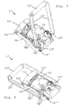
- Figs 3 to 5 in which the same numeric references generally designate the same elements, illustrate a part of another embodiment of a machine 1 according to the invention.
- Figs 3 and 4 illustrate a brewing unit 1' that is part of a beverage preparation module (not further shown) and connected to a handle 10',12'.
- Brewing unit 1' has a front part 14 and a rear part 15. Front and rear parts 14,15 can be moved apart ( Fig. 3 ) to form between them passage 7 for the insertion of a capsule and may be moved together ( Fig. 4 ) around the inserted capsule for closing passage 7, for forming a brewing chamber around the capsule and for circulating liquid, e.g. water, through the chamber and the capsule therein to form a beverage.
- Front and rear parts 14,15 can be moved apart ( Fig. 3 ) to form between them passage 7 for the insertion of a capsule and may be moved together ( Fig. 4 ) around the inserted capsule for closing passage 7, for forming a brewing chamber around the capsule and for circulating liquid, e.g. water, through the chamber and the capsule therein to form a beverage.
- liquid e.g. water
- Handle 10',12' is movable between a transfer position ( Fig. 3 ) in which parts 14,15 are spaced apart to form passage 7 and a circulation position ( Figs 4 and 5 ) in which parts 14,15 are urged together around a capsule for circulating liquid through the capsule.
- the handle has a drive portion 12' arranged to be contacted and driven by a human hand.
- Drive portion 12' can be transverse and extend between a pair of levers 10' forming therewith generally a u-shape. Hence, drive portion 12' forms a middle part of handle 10',12'.
- Levers 10' are pivotally mounted opposite drive portion 12' about a pivot axis 13' in rear part 15 of brewing unit 1'.
- Lever 10' extends beyond pivot axis 13' and is connected to an extremity of a traction arm 16 via a pivot joint 16'.
- An opposite extremity of traction arm 16 is connected via a second pivot joint 16" to front part 14 of brewing unit 1'.
- moving handle 10',12' from the transfer position ( Fig. 3 ) to the circulation position ( Fig. 4 ) causes front part 14 to be pulled against rear part 15 via traction arm 16.
- the relative movement of parts 14,15 may be further assisted by a hydraulic system (not shown), in particular for tightly closing the brewing unit.
- drive portion 12' forms a part of least counter-force of handle 10' , 12' against hand 50 while driving the handle.
- drive portion 12 may have a surface or profile specially adapted for being hand driven, e.g. the surface of drive portion 12 may include a means, such as a surface structure or composition, in particular an anti-skid surface that provides friction against a human hand.
- Fig. 5 illustrates a part of machine 1 with its housing 2 and handle 10',12' in the circulation position.
- Machine 1 has a user-interface 20a,20b for initiating circulation of liquid through the ingredient in the beverage preparation module.
- handle 10',12' and user-interface 20a,20b are arranged so that this user-interface is operable by human hand 50 while the hand is still in contact with drive portion 12' of the handle upon driving handle 10', 12' into its circulation position.
- Drive portion 12 is arranged to be pushed, pulled and/or seized by a human hand for driving handle 10',12'.
- User-interface 20a,20b can be operated by such a hand while the hand is still in a pushing, pulling and/or seizure position against drive portion 12' of the handle upon driving the handle into the circulation position ( Figs 4 and 5 ).
- handle 10',12' is pivotally movable over a top part of machine 1.
- machine 1 has a front face 2b bearing outlets 4a,4b,4c for delivering the beverage into a user-cup or user-mug (not shown) located therebelow.
- user-interface 20a,20b is located on front face 2b.
- User-interface 20a,20b may extend behind, above and below drive portion 12' when handle 10',12' is in the circulation position.
- User-interface 20a,20b includes four user-selectors, namely three upper push or touch buttons 20a and one lower touch button 20b. The various buttons may trigger the dispensing of beverages differing in size and/or flavour.
- buttons 20a are arranged for selection of three different dispensing volumes, e.g. espresso coffee, lungo coffee or American coffee, and the lower button 20b may be arranged for selecting optional milk addition into the selected coffee.
- machine 1 is arranged to dispense coffee via outlet 4a, hot water via outlet 4b for mixing with coffee to prepare Americano coffee, and milk via outlet 4c for incorporation into any coffee or for dispensing as such into a cup or mug.
- a fluid circuit suitable for preparing Americano coffee or extra-long coffee is disclosed in EP 10152556.6 which is hereby incorporated by way of reference.
- the upper three buttons 20a are configured for selecting the size of a beverage to be prepared and initiating beverage preparation.
- the lower button 20b may serve a different purpose.
- the lower button is a master switch or a service switch.
- user-interface 20a,20b When handle 10', 12' is in the circulation position, user-interface 20a,20b may be spaced from drive portion 12' by a distance in the range of 1 to 10 cm. This distance depends on the length of arms 10' and the distance between pivoting points 13' and user-interface 20a,20b.
- a user may introduce with his/her hand 50 a flavouring ingredient capsule (not shown) into passage 7 down and along which the capsule is guided by gravity inbetween parts 14,15, and then use the same hand 50 to seize the adjacent drive portion 12' of the handle.
- a flavouring ingredient capsule (not shown)
- handle 10',12' and brewing unit 1' with the introduced capsule are brought from the transfer position into the circulation position ( Figs 4 and 5 ) in which the capsule is enclosed and secured ready for the circulation of liquid therethrough.
- drive portion 12' with actuating hand 50 is brought in front' of user-interface 20a,20b.
- a user may then operate user-interface 20a,20b, e.g. gripping handle 10',12' with fingers 51 and operating lower button 20b with thumb 52 or holding drive portion 12' with the palm of hand 50 and operating upper buttons 20a with fingers 51.
- the user does not have to move hand 50 away from drive portion 12' or involve his/her second hand to initiate beverage dispensing via outlets 4a,4b,4c.
- beverage dispensing via outlets 4a,4b,4c.
- the beverage machine of the invention is particularly simple and is configured, in a simple manner, to be easily and safely operated single-handed by a user with few movements.
Description
- The field of the invention pertains to machines for preparing beverages from a liquid circulating through a flavouring ingredient. In particular, the field pertains to the ergonomic handling of such machines by users in order to prepare a beverage.
- For the purpose of the present description, a "beverage" is meant to include any liquid food, such as tea, coffee, hot or cold chocolate, milk, soup, baby food, etc... A "capsule" is meant to include any pre-portioned beverage ingredient within an enclosing packaging of any material, in particular an airtight packaging, e.g. plastic, aluminium, recyclable and/or biodegradable packagings, and of any shape and structure, including soft pods or rigid cartridges containing the ingredient.
- Certain beverage preparation machines use capsules containing ingredients to be extracted or to be dissolved; for other machines, the ingredients are stored and dosed automatically in the machine or else are added at the time of preparation of the drink.
- Most coffee machines possess filling means that include a pump for liquid, usually water, which pumps the liquid from a source of water that is cold or indeed heated through heating means, such as a heating resistor, a thermoblock or the like.
- Such machine typically have a brewing unit for holding and extraction the beverage ingredient. To introduce the ingredient into the brewing unit and then remove the ingredient upon use, the brewing unit has a closure mechanism that may be driven by a handle that is operable by a user. Various configurations for manipulating the machine have been disclosed in the art.
-
EP 1 208 782US 2008/0006159 discloses a brewing unit that has a horizontally movable drawer for introducing an ingredient pouch and a vertically movable top part with a piercing mechanism for opening the pouch. These elements are driven by a generally U-shaped movable handle that can be pivoted from an upright open position down to a generally horizontal closed position.US 7,165,488 ,WO 2007/111884 andEP 1 829 469 - More recently, efforts have been specifically devoted to the ease of operation of a beverage preparation machine for a user and ergonomic configuration of such machines, as illustrated in the following documents.
-
EP 1 878 368EP 1 864 598WO 2009/074553 andWO 2010/015427 disclose beverage preparation machines that are configured so that they can be lifted single-handed by a user. - For allowing the user to control machine operation various systems have been disclosed in the art, for instance as mentioned in the following references:
AT 410 377 CH 682 798 DE 44 29 353 ,DE 202 00 419 ,DE 20 2006 019 039 ,DE 2007 008 590 ,EP 1 448 084EP 1 676 509 ,EP 08155851.2 FR 2 624 844GB 2 397 510US 4,377,049 ,US 4,458,735 ,US 4,554,419 ,US 4,767,632 ,US 4,954,697 ,US 5,312,020 ,US 5,335,705 ,US 5,372,061 ,US 5,375,508 ,US 5, 731, 981 ,US 5,645,230 ,US 5, 836, 236 ,US 5,959,869 ,US 6, 182, 555 ,US 6, 354, 341 ,US 6, 759, 072 ,US 2007/0157820 ,WO 97/25634 WO99/50172 WO 2004/030435 ,WO 2004/030438 ,WO 2006/063645 ,WO 2006/090183 ,WO 2007/003062 ,WO 2007/003990 ,WO 2008/104751 ,WO 2008/138710 ,WO 2008/138820 ,WO 2009/135821 andWO 2010/003932 . -
DE 20 2006 019 039 ,AT 410 377 US 4,377,049 ,US 4,554,419 ,US 4,954,697 ,US 5,685,435 ,US 6, 759, 072 ,US 6, 182, 555 ,WO 2004/030438 ,WO 2006/090183 ,WO 2007/003990 WO 2008/138710 andWO 2010/003932 disclose beverage dispensing machines with a generally upright front face having a lower open cavity for receiving a receptacle to be filled via a beverage outlet in the cavity and, on an upper part of the front face, above the opening of this cavity, a generally vertical upper screen, touch screen and/or touch pad arranged as a user-interface.FR 2 624 844 - More advanced user-interface systems may include user-movable laser pointers for setting a level of fill directly on a user-cup, as taught in
WO 2006/063645 , or a sensor for acquiring the position of a finger or a user-operated object pointing onto a desired level of fill on a cup, as disclosed inWO 2009/135821 , and filling automatically the cup to such a level. - However, there is still a need to further improve the ergonomics of a coffee machine arranged so that its operation by a user is facilitate, in particular accelerated.
- The invention thus relates to a machine for preparing a beverage as defined in the claims.
The machine includes: - a beverage preparation module for holding a flavouring ingredient, in particular a pre-portioned ingredient such as an ingredient supplied to such module within a capsule, and circulating a liquid, e.g. water, therethrough to form such beverage;
- a handle movable between a transfer position for loading the flavouring ingredient into the module and/or evacuating this ingredient from the module, and a circulation position for circulating the liquid through this ingredient; and
- a user-interface for initiating circulation of this liquid through the flavouring ingredient in the beverage preparation module.
- The handle has a drive portion arranged to be contacted and driven by a human hand to move the handle between the transfer position and the circulation position. The handle is movable from the transfer position to the circulation position.
- For instance, the machine is a coffee, tea or soup machine. The machine may be arranged for preparing within a brewing unit a beverage by passing hot or cold water or another liquid through a capsule containing a flavouring ingredient of the beverage to be prepared, such as ground coffee or tea or chocolate or cacao or milk powder.
- The brewing unit may be moved by the handle from a first configuration, namely a transfer configuration, in which the flavouring ingredient is introduced into the brewing unit and/or evacuated therefrom, and a second configuration, namely a circulation configuration, in which the liquid is circulated through the flavouring ingredient to prepare the beverage. The circulation and transfer configurations of the brewing unit typically correspond to the handle's circulation and transfer positions, respectively.
- Typically, the machine includes one or more of a pump, heater, drip tray, ingredient collector, liquid tank and fluid connection system for providing a fluid connection between the liquid tank and the brewing unit, etc... The configuration of a fluid circuit between a source of liquid, e.g. a reservoir, and a brewing unit, i.e. a suitable beverage preparation module, is for example disclosed in greater details in
WO 2009/074550 . - In accordance with the invention, the handle and the user-interface are arranged so that the user-interface is operable by the user's hand while this hand is still in contact with the drive portion of the handle upon driving the handle into the circulation position.
- It follows that a user operating the machine by moving the handle into a circulation position for circulating the liquid through the flavouring ingredient brings at the same time his or her hand to the interface for initiating the circulation of the liquid through the ingredient. In other words, the user does not have to displace his or her hand to a different location on the machine or use another hand to start the beverage making process after the flavouring ingredient has been properly positioned in the beverage preparation module by bringing the handle into the circulation position. Hence, the manual operation of the machine is simplified and accelerated by minimising the user's manipulation effort.
- The drive portion can be arranged to be pushed and/or pulled by a human hand for driving the handle, the user-interface being operable by the human hand while the hand is still in a pushing and/or pulling position against the drive portion of the handle upon driving the handle into the circulation position. The handle may be pushed by the user's fingertips and/or pulled by gripping the handle.
- The drive portion can be arranged to be seized by the human hand for driving the handle, the user-interface being operable by the human hand while the hand is still seizing the drive portion of the handle upon driving the handle into the circulation position.
- Hence, the handle and the interface may be so configured that the user can operate the interface with the hand used for bringing the handle into the circulation position without having to move the hand away from the handle.
- Advantageously, the drive portion forms a part of least counter-force of the handle against the human hand while driving the handle. Hence, in this configuration, the user will drive the handle to the circulation position by actuating the drive portion of the handle that generates least mechanical resistance during the movement.
- The user-interface may include at least one user-selector selected from push-buttons, turn-buttons, toggle-switches, slide buttons, touch-buttons, touch pads and touch screens. The user-interface may comprise a plurality of selectors for selecting different drinks, in particular drinks of different sizes and/or different types, such as espresso, regular coffee and/or lungos, extra-long coffee and milk coffee.
- The user-interface may be fixed to the machine's housing and the handle movable relative thereto, in particular pivotable relative to the housing.
- The handle is pivotally movable, in particular pivotally movable over a top part of the machine. The handle can be generally U-shaped, the drive portion forming in particular a middle part of the generally U-shaped handle. The handle can have a pair of levers and the drive portion between the levers, in particular a pair of levers having first end portions that are pivotally mounted and second end portions that are joined via the drive portion. The handle may be a single-arm lever, in particular a lever having a first end portion that is pivotally mounted and a second end portion that forms the drive portion.
- According to the invention, the machine has a front face bearing an outlet for delivering said beverage, the user-interface being located on said front face.
- The user-interface may extend below the drive portion when the handle is in the circulation position, the user-interface being optionally located in front of the handle. The user-interface may extend above and/or behind the drive portion when the handle is in the circulation position.
- When the handle is in the circulation position, the user-interface can be spaced from the drive portion by a distance in the range of 0 to 10 cm, in particular in the range of 0.5 to 7 cm such as 1 to 5 cm, optionally 1.5 to 3 cm.
- The beverage preparation machine may have a passage for introducing by gravity the flavouring ingredient, in particular within a capsule, into the beverage preparation module, the drive portion being located generally above and/or adjacent the passage when the handle is in the transfer position. Hence, the handle in its transfer position is located closely to the user's hand that inserts the ingredient into the machine's passage so that minimal movement of the hand is required from the insertion of the ingredient to manually actuating the handle.
- The invention will now be described with reference to the schematic drawings, wherein:
-
Figures 1 and 2 illustrate an example of a beverage machine which does not fall under the wording of the claims but is helpful for the understanding of the invention. -
Figures 3 to 5 illustrate part of an embodiment of a beverage machine according to the invention. -
Figures 1 and 2 illustrate an example of abeverage preparation machine 1. -
Machine 1 can be electrically powered, typically by the mains, via anelectric cord 9. -
Machine 1 has an internal beverage preparation module covered by ahousing 2. The beverage preparation module is arranged for holding a flavouring ingredient, in particular a pre-portioned ingredient such as an ingredient supplied to such module within a capsule, and circulating a liquid therethrough to form the beverage. - The liquid, e.g. water, may be stored and supplied to the beverage preparation module from a
tank 3. The beverage, upon formation, can be dispensed via anoutlet 4 to adispensing area 5,5', e.g. a support for holding a user cup or mug. The dispensing area may include afirst cup support 5 that is movable away from underoutlet 4 so as to give access to a lower second cup support 5' for larger cups, e.g. for dispensing lungos or extra-large beverages. The lower cup support 5' may be connected to abase 8 ofmachine 1. Suitable movable cup supports are for example disclosed inEP 1867260 and inWO 2009/074557 , the contents of which are hereby incorporated by way of reference. -
Machine 1 also includes a steam and/or hot water generator connected to an outlet 4', e.g. for the preparation of frothed milk and/or tea. - Adjacent to the beverage preparation module,
machine 1 may have acollector 6 for used flavouring ingredient, e.g. ground coffee or tea upon brewing, for instance contained within capsules.Collector 6 may be positioned underneath the beverage preparation module to collect upon beverage preparation the used flavouring ingredient evacuated tocollector 6, e.g. by gravity. Suitable collectors are for example disclosed inWO 2009/074559 and inWO 2009/135869 , which are hereby incorporated by way of reference. -
Machine 1 has ahandle 10 movable between: a transfer position for loading the ingredient, e.g. within a capsule, into the module and/or evacuating such ingredient from the module; and a circulation position for circulating the liquid through the ingredient. - Typically, handle 10 actuates an ingredient holder with an ingredient chamber, such as a brewing unit, of the beverage preparation module from: a transfer position for insertion of the flavouring ingredient into the holder and/or evacuation of this ingredient therefrom; and a circulation position for circulating the liquid through this ingredient in the ingredient holder to form the beverage. Typically, the ingredient holder, e.g. a brewing unit, has two relatively movable parts that are moved apart for opening the ingredient holder into the transfer position and moved together for closing the ingredient holder into the circulation position. In the circulation position, the ingredient holder may tightly enclose the flavouring ingredient to ensure proper guidance of the liquid through the ingredient.
- The circulation position is illustrated in
Fig. 2 , in which handle 10 is resting on or in atop face 2a ofmachine 1. Inparticular handle 10 can be flush withhousing 2. - As shown in
Figs 1 and 2 , handle 10 is a single-arm lever generally shaped as a straight bar that is slightly curved or bent at itsextremity 11 for ergonomic reasons, namely for facilitating the manual application of force ontohandle 10 by a convenient orientation ofcontact surface 12 forhand 50 whenhandle 10 is moved from the transfer position to the circulation position. In the circulation position (Fig. 2 ), handle 10 with itsextremity 11 may be flush withhousing 2 that has a corresponding shape, e.g. to facilitate cleaning of the surface ofhousing 2. - Hence, handle 10 has a
drive portion 12 arranged to be contacted and driven by ahuman hand 50 to move the handle between the transfer position in which the flavouring ingredient, e.g. enclosed in a capsule, is inserted into the beverage preparation module for instance via apassage 7, and the circulation position in which the flavouring ingredient is housed in the beverage preparation module and liquid may be circulated therethrough to form the beverage. -
Fig. 1 shows handle 10 in an intermediate position between the transfer position and the circulation position (Fig. 2 ). In the transfer position, handle 10 entirely uncoverspassage 7 for allowing the insertion of the flavouring ingredient, e.g. within a capsule, into the beverage preparation module. -
Passage 7 can be arranged for introduction by gravity of the flavouring ingredient into the beverage preparation module,drive portion 12 being located generally above and/oradjacent passage 7 whenhandle 10 is in the transfer position to facilitate the coordination between manual introduction of a flavouring ingredient, e.g. within a capsule, intopassage 7 and manually actuatinghandle 10, in particular using thesame hand 50. - Furthermore,
machine 1 includes a user-interface 20 for initiating circulation of the liquid through the flavouring ingredient in the beverage preparation module. - The beverage preparation module typically includes one or more of the following components:
- a) the ingredient holder, such as a brewing unit, for receiving the flavouring ingredient of this beverage, in particular a pre-portioned ingredient supplied within a capsule, and for guiding an incoming flow of liquid, such as water, through this ingredient to
beverage outlet 4; - b) an in-line heater, such as a thermoblock, for heating this flow of liquid to be supplied to the ingredient holder;
- c) a pump for pumping this liquid through the in-line heater;
- d) one or more fluid connecting members for guiding this liquid from a source of liquid, such as
tank 3 of liquid, tobeverage outlet 4; - e) an electric control unit, in particular comprising a printed circuit board (PCB), for receiving instructions from a user via an interface and for controlling the in-line heater and the pump; and
- f) one or more electric sensors for sensing at least one operational characteristic selected from characteristics of the ingredient holder, the in-line heater, the pump,
liquid reservoir 3,ingredient collector 6, a flow of this liquid, a pressure of this liquid and a temperature of this liquid, and for communicating such characteristic(s) to the control unit. - The heater may be a thermoblock or an on demand heater (ODH), for instance an ODH type disclosed in
EP 1 253 844EP 1 380 243EP 1 809 151WO 2005/004683 ,WO2007/135136 andWO 2009/043630 , which are hereby incorporated by way of reference. Suitable beverage preparation modules are for instance disclosed inWO 2009/074550 andWO 2009/130099 which are hereby incorporated by way of reference. - In accordance with the invention, handle 10 and user-
interface 20 are arranged so that user-interface 20 is operable by ahuman hand 50 while it is still in contact withdrive portion 12 ofhandle 10 upon drivinghandle 10 into the circulation position, as illustrated inFig. 2 . - For instance, drive
portion 12 is contacted and actuatable by one or more of the index finger, middle finger, ring finger andlittle finger 51, user-interface 20 being operable by the hand'sthumb 52 while finger(s) 51 is/are still in contact withhandle 10, i.e. without having to movehand 50 away fromhandle 10 after movinghandle 10 into its circulation position. For convenience,drive portion 12 may have a surface or profile specially adapted for being hand driven, e.g. the surface ofdrive portion 12 may include a means, such as a surface structure or composition, in particular an anti-skid surface that provides friction againsthand 50. - As illustrated in
Fig. 2 ,drive portion 12 is arranged to be pushed byhuman hand 50 for drivinghandle 10. User-interface 20 is operable byhand 50 while it is still in a pushing position againstdrive portion 12 upon drivinghandle 10 into the circulation position (Fig. 2 ). User-interface 20 may include a plurality of user selectors for initiating preparation of beverages of different flavours and/or of different sizes and/or different types. For instance, user-interface 20 includes a first user-selector and a second user-selector, e.g. in the form of push-buttons, for selecting the dispensing of espresso coffee and of lungo coffee. -
Machine 1 illustrated inFigs 1 and 2 has afront face 2b bearing outlet 4 for delivering the beverage, user-interface 20 being located onfront face 2b. In particular,user interface 20 is located belowdrive portion 12 to be easily accessible by the user'shand 50 while still in position ondrive portion 12 onhandle 10 upon reaching the handle's circulation position (Fig. 2 ). For instance, whenhandle 10 is in the circulation position, user-interface 20 is spaced fromdrive portion 12 by a distance in the range of 2 to 4 cm. -
Drive portion 12 may form a part of least counter-force ofhandle 10 againsthuman hand 50 while drivinghandle 10. For instance, handle 10 is arranged to pivot at afirst end portion 13 thereof and driveportion 12 is located at the opposite end ofhandle 10 so that the lever arm is maximised and the force applied byhand 50 and necessary to vanquish the counter-force of the system minimised. -
Figs 3 to 5 , in which the same numeric references generally designate the same elements, illustrate a part of another embodiment of amachine 1 according to the invention.Figs 3 and 4 illustrate a brewing unit 1' that is part of a beverage preparation module (not further shown) and connected to a handle 10',12'. - Brewing unit 1' has a
front part 14 and arear part 15. Front andrear parts Fig. 3 ) to form between thempassage 7 for the insertion of a capsule and may be moved together (Fig. 4 ) around the inserted capsule for closingpassage 7, for forming a brewing chamber around the capsule and for circulating liquid, e.g. water, through the chamber and the capsule therein to form a beverage. - Handle 10',12' is movable between a transfer position (
Fig. 3 ) in whichparts passage 7 and a circulation position (Figs 4 and5 ) in whichparts rear part 15 of brewing unit 1'. Lever 10' extends beyond pivot axis 13' and is connected to an extremity of atraction arm 16 via a pivot joint 16'. An opposite extremity oftraction arm 16 is connected via a second pivot joint 16" tofront part 14 of brewing unit 1'. - Hence, moving handle 10',12' from the transfer position (
Fig. 3 ) to the circulation position (Fig. 4 ) causesfront part 14 to be pulled againstrear part 15 viatraction arm 16. The relative movement ofparts - Like in the previous embodiment, drive portion 12' forms a part of least counter-force of handle 10' , 12' against
hand 50 while driving the handle. - As mentioned above, for convenience,
drive portion 12 may have a surface or profile specially adapted for being hand driven, e.g. the surface ofdrive portion 12 may include a means, such as a surface structure or composition, in particular an anti-skid surface that provides friction against a human hand. - Further details of a brewing unit 1' and extraction module of this kind are disclosed in greater details in co-pending application
EP 09172187.8 EP 09177592.4 WO 2007/135135 . -
Fig. 5 illustrates a part ofmachine 1 with itshousing 2 and handle 10',12' in the circulation position. -
Machine 1 has a user-interface - In accordance with the invention, handle 10',12' and user-
interface human hand 50 while the hand is still in contact with drive portion 12' of the handle upon driving handle 10', 12' into its circulation position. -
Drive portion 12 is arranged to be pushed, pulled and/or seized by a human hand for driving handle 10',12'. User-interface Figs 4 and5 ). - As illustrated in
Figs 3 to 5 , handle 10',12' is pivotally movable over a top part ofmachine 1. Moreover,machine 1 has afront face 2b bearing outlets - As illustrated in
Fig. 5 , user-interface front face 2b. User-interface interface touch buttons 20a and onelower touch button 20b. The various buttons may trigger the dispensing of beverages differing in size and/or flavour. - For instance, the upper three
buttons 20a are arranged for selection of three different dispensing volumes, e.g. espresso coffee, lungo coffee or American coffee, and thelower button 20b may be arranged for selecting optional milk addition into the selected coffee. For example,machine 1 is arranged to dispense coffee viaoutlet 4a, hot water viaoutlet 4b for mixing with coffee to prepare Americano coffee, and milk viaoutlet 4c for incorporation into any coffee or for dispensing as such into a cup or mug. A fluid circuit suitable for preparing Americano coffee or extra-long coffee is disclosed inEP 10152556.6 - In a variation, the upper three
buttons 20a are configured for selecting the size of a beverage to be prepared and initiating beverage preparation. Thelower button 20b may serve a different purpose. For instance, the lower button is a master switch or a service switch. - When handle 10', 12' is in the circulation position, user-
interface interface - Hence, in the transfer position of handle 10',12' (
Fig. 3 ), a user may introduce with his/her hand 50 a flavouring ingredient capsule (not shown) intopassage 7 down and along which the capsule is guided bygravity inbetween parts same hand 50 to seize the adjacent drive portion 12' of the handle. By pulling down drive portion 12' over the top and front faces 2a,2b ofmachine 1, handle 10',12' and brewing unit 1' with the introduced capsule are brought from the transfer position into the circulation position (Figs 4 and5 ) in which the capsule is enclosed and secured ready for the circulation of liquid therethrough. - By driving handle 10',12' with
hand 50 into the circulation position, drive portion 12' with actuatinghand 50 is brought in front' of user-interface hand 50 still on drive portion 12' a user may then operate user-interface fingers 51 and operatinglower button 20b withthumb 52 or holding drive portion 12' with the palm ofhand 50 and operatingupper buttons 20a withfingers 51. Hence, the user does not have to movehand 50 away from drive portion 12' or involve his/her second hand to initiate beverage dispensing viaoutlets - The beverage machine of the invention is particularly simple and is configured, in a simple manner, to be easily and safely operated single-handed by a user with few movements.
Claims (17)
- A machine (1) for preparing a beverage having:- a top part (2a);- a front face (2b) bearing an outlet (4,4a,4b,4c) for delivering said beverage- a beverage preparation module (1') for holding a flavouring ingredient, in particular a pre-portioned ingredient such as an ingredient supplied to such module within a capsule, and circulating a liquid therethrough to form said beverage;- a handle (10,12,10',12') pivotally movable over the top part (2a) between a transfer position for loading said ingredient into the module and/or evacuating said ingredient from the module, and a circulation position for circulating said liquid through said ingredient; and- a user-interface (20,20a,20b) for initiating circulation of said liquid through said ingredient in the beverage preparation module,the handle having a drive portion (12,12') arranged to be contacted and driven by a human hand (50) to move the handle between the transfer position and the circulation position,
wherein the user interface (20,20a,20b) is located on the front face (2b) and wherein the handle (10,12,10',12') and the user-interface (20,20a,20b) are arranged so that said user-interface is operable by said human hand (50) while said hand is still in contact with the drive portion (12,12') of the handle upon driving the handle into the circulation position,
wherein the handle (10',12') has a pair of levers (10') and the drive portion (12') therebetween, the pair of levers having first end portions (13') that are pivotally mounted and second end portions that are joined via the drive portion (12'),
wherein the drive portion (12') forms a part of least counter-force of the handle (10',12') against said human hand (50) while driving the handle,
wherein the handle (10',12') is generally U-shaped, and
wherein the drive portion (12') forms a middle part of the generally U-shaped handle. - A machine (1) for preparing a beverage having:- a top part (2a);- a front face (2b) bearing an outlet (4,4a,4b,4c) for delivering said beverage- a beverage preparation module (1') for holding a flavouring ingredient, in particular a pre-portioned ingredient such as an ingredient supplied to such module within a capsule, and circulating a liquid therethrough to form said beverage;- a handle (10,12,10',12') pivotally movable over the top part (2a) between a transfer position for loading said ingredient into the module and/or evacuating said ingredient from the module, and a circulation position for circulating said liquid through said ingredient; and- a user-interface (20,20a,20b) for initiating circulation of said liquid through said ingredient in the beverage preparation module,the handle having a drive portion (12,12') arranged to be contacted and driven by a human hand (50) to move the handle between the transfer position and the circulation position,
wherein the user interface (20,20a,20b) is located on the front face (2b) and wherein the handle (10,12,10',12') and the user-interface (20,20a,20b) are arranged so that said user-interface is operable by said human hand (50) while said hand is still in contact with the drive portion (12,12') of the handle upon driving the handle into the circulation position,
characterised in that
the user-interface (20a,20b) extends above the drive portion (12') when the handle (10',12') is in the circulation position. - The machine of claim 1 or 2, wherein the drive portion (12,12') of the handle (10,12,10',12') is arranged to be pushed and/or pulled by said human hand (50) for driving the handle, the user-interface (20,20a,20b) being operable by said human hand while said hand is still in a pushing and/or pulling position against the drive portion upon driving the handle into the circulation position.
- The machine of claim 1, 2 or 3, wherein the drive portion (12') of the handle (10,12,10',12') is arranged to be seized by said human hand (50) for driving the handle, the user-interface (20a,20b) being operable by said human hand while said hand is still seizing the drive portion (12') upon driving the handle into the circulation position.
- The machine of any preceding claim when dependent on claim 2, wherein the drive portion (12,12') forms a part of least counter-force of the handle (10,12,10',12') against said human hand (50) while driving the handle.
- The machine of any preceding claim, wherein the user-interface (20,20a,20b) includes at least one user-selector selected from push-buttons, turn-buttons, toggle-switches, slide buttons, touch-buttons, touch pads and touch screens.
- The machine of claim 6, wherein the user-interface (20,20a,20b) comprise a plurality of selectors for selecting different drinks, in particular drinks of different sizes and/or different types.
- The machine of any preceding claim when dependent on claim 2, wherein the handle (10',12') is generally U-shaped.
- The machine of claim 8, wherein the drive portion (12') forms a middle part of the generally U-shaped handle.
- The machine of claim 2 or of any of claims 3 to 9 when dependent on claim 2, wherein the handle (10',12') has a pair of levers (10') and the drive portion (12') therebetween, in particular a pair of levers having first end portions (13') that are pivotally mounted and second end portions that are joined via the drive portion (12').
- The machine of claim 2 or of any one of claims 3 to 7 when dependent on claim 2, wherein the handle (10,12) is a single-arm lever.
- The machine of claim 11, wherein the lever has a first end portion (13) that is pivotally mounted and another end portion that forms said drive portion (12).
- The machine of any preceding claim, wherein the user-interface (20,20b) extends below the drive portion when the handle (10,12,10',12') is in the circulation position, the user-interface (20) being optionally located in front of the handle (10,12).
- The machine of claim 1 or of any of claims 1 to 9 or 13 when dependent on claim 1, wherein the user-interface (20a,20b) extends above and/or behind the drive portion (12') when the handle (10',12') is in the circulation position.
- The machine of claim 2 or of any of claims 3 to 13 when dependent on claim 2, wherein the user-interface (20a,20b) extends behind the drive portion (12') when the handle (10',12') is in the circulation position.
- The machine of any preceding claim, wherein, when the handle (10,12,10',12') is in the circulation position, the user-interface (20,20a,20b) is spaced from the drive portion (12,12') by a distance in the range of 0 to 10 cm, in particular in the range of 0.5 to 7 cm such as 1 to 5 cm, optionally 1.5 to 3 cm.
- The machine of any preceding claim, which has a passage (7) for introducing by gravity said flavouring ingredient into the beverage preparation module, the drive portion (12,12') being located generally above and/or adjacent the passage when the handle (10,12,10',12') is in the transfer position.
Priority Applications (1)
| Application Number | Priority Date | Filing Date | Title |
|---|---|---|---|
| EP11720518.7A EP2571404B2 (en) | 2010-05-21 | 2011-05-20 | Ergonomic handle & user-interface |
Applications Claiming Priority (3)
| Application Number | Priority Date | Filing Date | Title |
|---|---|---|---|
| EP10163649 | 2010-05-21 | ||
| EP11720518.7A EP2571404B2 (en) | 2010-05-21 | 2011-05-20 | Ergonomic handle & user-interface |
| PCT/EP2011/058222 WO2011144719A1 (en) | 2010-05-21 | 2011-05-20 | Ergonomic handle & user-interface |
Publications (3)
| Publication Number | Publication Date |
|---|---|
| EP2571404A1 EP2571404A1 (en) | 2013-03-27 |
| EP2571404B1 EP2571404B1 (en) | 2014-04-16 |
| EP2571404B2 true EP2571404B2 (en) | 2017-10-25 |
Family
ID=42752426
Family Applications (1)
| Application Number | Title | Priority Date | Filing Date |
|---|---|---|---|
| EP11720518.7A Active EP2571404B2 (en) | 2010-05-21 | 2011-05-20 | Ergonomic handle & user-interface |
Country Status (4)
| Country | Link |
|---|---|
| EP (1) | EP2571404B2 (en) |
| ES (1) | ES2464775T3 (en) |
| PT (1) | PT2571404E (en) |
| WO (1) | WO2011144719A1 (en) |
Families Citing this family (34)
| Publication number | Priority date | Publication date | Assignee | Title |
|---|---|---|---|---|
| AU2013217595B2 (en) * | 2012-02-09 | 2017-04-20 | Keurig Green Mountain, Inc. | Beverage forming device and method with multi-part beverage cartridge holder |
| CA2862924C (en) | 2012-02-09 | 2020-01-07 | Keurig Green Mountain, Inc. | Beverage forming device and method with activation button |
| ES2828253T3 (en) | 2014-07-09 | 2021-05-25 | Nestle Sa | Device for connecting a beverage machine to a distribution network with safe flow interruption |
| EP3166456B1 (en) | 2014-07-09 | 2018-09-26 | Nestec S.A. | Accessory for supplying automatically a beverage machine with liquid from a distribution network |
| EP3166458B1 (en) | 2014-07-09 | 2021-05-05 | Société des Produits Nestlé S.A. | Coupling of a device for connecting a beverage machine to a distribution network |
| WO2016005350A1 (en) | 2014-07-09 | 2016-01-14 | Nestec S.A. | Device for connecting a beverage machine to a distribution network with safe monitoring |
| EP3223667A1 (en) | 2014-11-27 | 2017-10-04 | Nestec S.A. | Ergonomic handle arrangement |
| WO2016083485A1 (en) | 2014-11-27 | 2016-06-02 | Nestec S.A. | Liquid dispensing machine with manual drop stop |
| EP3223668B1 (en) | 2014-11-27 | 2018-11-21 | Nestec S.A. | Liquid dispensing machine with compact drop stop |
| RU2713330C2 (en) | 2015-11-11 | 2020-02-04 | Сосьете Де Продюи Нестле С.А. | Simple connection of fluid tank with beverage preparation device |
| EP3175749A1 (en) | 2015-12-01 | 2017-06-07 | Qbo Coffee GmbH | Drink preparation machine for preparing a drink |
| EP3175746A1 (en) * | 2015-12-01 | 2017-06-07 | Qbo Coffee GmbH | Machine for making beverages |
| RU2748515C2 (en) | 2016-09-09 | 2021-05-26 | Сосьете Де Продюи Нестле С.А. | Beverage preparation device with ergonomic control |
| US11246448B2 (en) | 2016-10-11 | 2022-02-15 | Societe Des Produits Nestle S.A. | Liquid dispensing machine with drop stop |
| WO2018069268A1 (en) | 2016-10-11 | 2018-04-19 | Nestec Sa | Liquid dispensing machine with speed regulator |
| BR112019008836A2 (en) | 2016-11-09 | 2019-07-09 | Pepsico Inc | carbonated beverage manufacturing sets, methods, and systems |
| EP3629857A1 (en) | 2017-06-01 | 2020-04-08 | Société des Produits Nestlé S.A. | Beverage machine with a storable dispensing head |
| US11700969B2 (en) | 2017-06-01 | 2023-07-18 | Societe Des Produits Nestle S.A. | Beverage machine with a collapsible interface |
| CN110662468B (en) | 2017-06-01 | 2022-04-29 | 雀巢产品有限公司 | Beverage machine with ergonomic power switch |
| EP3629854A1 (en) | 2017-06-01 | 2020-04-08 | Société des Produits Nestlé S.A. | Beverage machine with a stablizing foot |
| DK3638085T3 (en) | 2017-06-13 | 2021-03-29 | Nestle Sa | BEVERAGE PREPARATION MACHINE WITH Capsule RECOGNITION |
| CN111432692B (en) | 2017-12-20 | 2023-08-25 | 雀巢产品有限公司 | Beverage preparation machine with foam refining means |
| PT3727109T (en) | 2017-12-20 | 2022-03-17 | Nestle Sa | Beverage preparation machine with drop evacuation |
| JP7308200B2 (en) | 2017-12-20 | 2023-07-13 | ソシエテ・デ・プロデュイ・ネスレ・エス・アー | Convenient anti-drip beverage preparation machine |
| WO2019154527A1 (en) | 2018-02-09 | 2019-08-15 | Societe Des Produits Nestle S.A. | Beverage preparation machine with capsule recognition |
| WO2019158542A1 (en) | 2018-02-14 | 2019-08-22 | Societe Des Produits Nestle S.A. | Used capsule receptacle for beverage machines |
| CN112689466B (en) | 2018-09-27 | 2023-09-05 | 雀巢产品有限公司 | Self-adaptive service unit of beverage machine |
| EP3628195A1 (en) | 2018-09-27 | 2020-04-01 | Société des Produits Nestlé S.A. | Beverage preparation machine with recipient detection |
| WO2020064984A1 (en) | 2018-09-27 | 2020-04-02 | Société des Produits Nestlé SA | Beverage machine with an actuation distribution |
| CA3121432A1 (en) | 2018-12-12 | 2020-06-18 | Societes Des Produits Nestle S.A. | Beverage preparation machine with capsule recognition |
| TR201905030A2 (en) | 2019-04-03 | 2020-10-21 | Arcelik As | A COFFEE MACHINE WITH AN EXTERNAL WATER TANK |
| BR112022013134A2 (en) | 2020-02-05 | 2022-09-06 | Nestle Sa | MACHINE FOR BEVERAGE PREPARATION WITH CAPSULE RECOGNITION |
| WO2021156268A1 (en) | 2020-02-05 | 2021-08-12 | Societe Des Produits Nestle S.A. | Beverage preparation machine with capsule recognition |
| WO2023061991A1 (en) | 2021-10-13 | 2023-04-20 | Société des Produits Nestlé S.A. | Ergonomic beverage machine |
Citations (10)
| Publication number | Priority date | Publication date | Assignee | Title |
|---|---|---|---|---|
| EP0730425B1 (en) † | 1994-09-22 | 1999-05-19 | Eugster/Frismag AG | Brewing head for coffee portion capsules in an espresso machine |
| EP1440640A2 (en) † | 2003-01-24 | 2004-07-28 | Kraft Foods R & D, Inc. | Machine for the preparation of beverages |
| WO2005060801A1 (en) † | 2003-12-12 | 2005-07-07 | Keurig, Incorporated | Brew chamber for a single serve beverage brewer |
| EP1878368A1 (en) † | 2006-07-11 | 2008-01-16 | Nestec S.A. | Beverage production machine with functional block and support base |
| WO2008072295A1 (en) † | 2006-12-11 | 2008-06-19 | Devicestyle Holdings Corporation | Espresso machine |
| EP1992263A1 (en) † | 2007-05-16 | 2008-11-19 | Nestec S.A. | Beverage production module and method for operating a beverage production module |
| EP1912542B1 (en) † | 2005-08-05 | 2009-02-11 | Delica AG | Apparatus for extracting an extraction substance, which is contained in a capsule, with a liquid extraction means |
| WO2009074557A1 (en) † | 2007-12-12 | 2009-06-18 | Nestec S.A. | Liquid food or beverage machine having a drip tray and a cup support |
| WO2009135034A1 (en) † | 2008-04-30 | 2009-11-05 | Bunn-O-Matic Corporation | Brewer including substance removal assembly |
| WO2010032271A1 (en) † | 2008-09-18 | 2010-03-25 | Saeco Ipr Limited | Infusion device for coffee machines and the like |
Family Cites Families (61)
| Publication number | Priority date | Publication date | Assignee | Title |
|---|---|---|---|---|
| US4377049A (en) | 1980-05-22 | 1983-03-22 | Pepsico Inc. | Capacitive switching panel |
| US4458735A (en) | 1982-09-30 | 1984-07-10 | Medetec Industries, Inc. | Dispensing arrangement for a beverage such as a milkshake |
| US4554419A (en) | 1983-12-02 | 1985-11-19 | The Coca-Cola Company | Touch selection panel for a vending machine |
| JPS6282496A (en) | 1985-10-05 | 1987-04-15 | サンデン株式会社 | Self-service store apparatus |
| DE3615158C2 (en) | 1986-05-05 | 1990-11-15 | Cafina Ag | Method for preparing a plurality of coffee portions |
| FR2624844B1 (en) | 1987-12-18 | 1990-07-20 | Andries Eric | APPARATUS FOR MAKING BEVERAGES MADE OF MIXTURES OF INGREDIENTS, ESPECIALLY COCKTAILS |
| JP2960590B2 (en) | 1991-09-27 | 1999-10-06 | 東芝機械株式会社 | Automatic dispensing device for sparkling beverages |
| DE4137324C1 (en) | 1991-11-13 | 1993-02-04 | Cis Elektrogeraete Ag, Hinwil, Ch | |
| CH682798A5 (en) | 1991-11-15 | 1993-11-30 | Salvis Ag | Coffee machine with grinder, brewer and dispenser in one unit - has all three modules in one structure, behind front and each is accessible from top or front, brewing module has two brewing stations |
| US5731981A (en) | 1992-06-08 | 1998-03-24 | Azbar, Inc. | Beverage dispensing system for bar |
| US5372061A (en) | 1993-04-14 | 1994-12-13 | Avanti Espresso U.S.A., Inc. | Espresso/cappuccino apparatus and method |
| US5375508A (en) | 1993-12-29 | 1994-12-27 | Bunn-O-Matic Corporation | Digital brewer control |
| US5744793A (en) | 1994-02-28 | 1998-04-28 | Electro-Pro, Inc. | Triangulation position-detection and integrated dispensing valve |
| DE4429353A1 (en) | 1994-08-19 | 1996-02-22 | Joachim Koeninger | Universal automatic drinks dispenser |
| IT1280833B1 (en) | 1995-03-31 | 1998-02-11 | Enrico Marogna | DEVICE FOR CONTROL OF COFFEE GRINDING, GRINDER DOSING MACHINE EQUIPPED WITH THIS DEVICE AND PROCEDURE FOR THE |
| US5685435A (en) | 1995-05-08 | 1997-11-11 | Mars Incorporated | Method and apparatus for automatic bulk vending |
| US5756403A (en) | 1995-12-29 | 1998-05-26 | Philips Electronics North America | Method of preferentially etching a semiconductor substrate with respect to epitaxial layers |
| US5959869A (en) | 1996-12-03 | 1999-09-28 | The Coca-Cola Company | Vending machine controller and system |
| US5836236A (en) | 1997-03-03 | 1998-11-17 | Rolfes; Patrick J. | Coffee brewer and hot water dispenser |
| DE19710073A1 (en) | 1997-03-12 | 1998-10-01 | Daimler Benz Ag Intellectual P | Device and method for surge protection |
| DE29709463U1 (en) | 1997-05-30 | 1997-07-31 | Frei Willi | Flat transparent cover |
| EP0917218B1 (en) | 1997-11-05 | 2006-03-01 | Philips Consumer Communications France | A battery unit and a portable battery-operated device including such a battery unit |
| US6082419A (en) | 1998-04-01 | 2000-07-04 | Electro-Pro, Inc. | Control method and apparatus to detect the presence of a first object and monitor a relative position of the first or subsequent objects such as container identification and product fill control |
| AT410377B (en) | 1998-07-27 | 2003-04-25 | Dosy Star Electronics Vertrieb | DRINKS OUTPUT DEVICE |
| US6182555B1 (en) | 1999-04-07 | 2001-02-06 | Red River Tea Company | Apparatus and methods for brewing and dispensing beverages |
| US6759072B1 (en) | 1999-08-14 | 2004-07-06 | The Procter + Gamble Co. | Methods and systems for utilizing delayed dilution, mixing and filtration for providing customized beverages on demand |
| US6354341B1 (en) | 1999-11-10 | 2002-03-12 | Shurflo Pump Manufacturing Co., Inc. | Rapid comestible fluid dispensing apparatus and method |
| US6459854B1 (en) | 2000-01-24 | 2002-10-01 | Nestec S.A. | Process and module for heating liquid |
| EP1208782B1 (en) | 2000-11-28 | 2004-08-25 | Societe Des Produits Nestle S.A. | Percolation device |
| DE10154046A1 (en) | 2001-11-02 | 2003-05-22 | Miele & Cie | household appliance |
| DE20200419U1 (en) | 2002-01-12 | 2002-05-29 | Wik Far East Ltd | Electrical household or personal care device that is stationary during operation |
| PT1380243E (en) | 2002-07-12 | 2008-07-31 | Nestec Sa | A device for the heating of a liquid |
| WO2004030435A2 (en) | 2002-10-02 | 2004-04-15 | Automated Beverage Technologies Ltd | Dispenser |
| BR0315012B1 (en) | 2002-10-04 | 2013-05-28 | Touch panel assembly for a beverage dispenser, and method for enhancing a user interface. | |
| GB2397510A (en) | 2003-01-24 | 2004-07-28 | Kraft Foods R & D Inc | Cartridge and machine for the preparation of beverages |
| EP1495702A1 (en) | 2003-07-10 | 2005-01-12 | Nestec S.A. | Device for the extraction of a cartridge |
| CA2544686C (en) | 2003-11-07 | 2013-05-14 | Bunn-O-Matic Corporation | Adjustable volume brewer |
| EP1634520A1 (en) | 2004-09-13 | 2006-03-15 | Nestec S.A. | Device and method for heating a liquid |
| EP1980525A3 (en) | 2004-12-14 | 2009-12-30 | Nestec S.A. | Device and method for controlling the filling of a cup in a drinks vending machine such as a coffee machine |
| EP1676509A1 (en) | 2004-12-30 | 2006-07-05 | Rhea Vendors S.p.A. | Process and apparatus for controlling the preparation of brewed beverages |
| GB2451005B (en) | 2005-02-28 | 2009-09-23 | Coffee Nation Ltd | Apparatus for preparing beverages |
| MX2007014288A (en) | 2005-07-01 | 2008-02-07 | Saeco Ipr Ltd | Operator's device for automatic hot beverage dispensers. |
| CH697974B1 (en) | 2005-07-01 | 2009-04-15 | Saeco Ipr Ltd | Operating device for hot beverage vending machines. |
| DE202006019039U1 (en) | 2005-12-19 | 2007-03-08 | Mayer, Martin | Drinks dispenser especially for water also has information display formed by flat screen with liquid crystals, diodes or plasma unit to provide information and advertising |
| DE202006002678U1 (en) | 2006-02-17 | 2006-04-20 | Eugster/Frismag Ag | Coffee machine for preparing a coffee beverage by means of packaged, pre-portioned Kaffeepouches |
| FR2898028B1 (en) | 2006-03-01 | 2008-05-16 | Seb Sa | INFUSING MACHINE COMPRISING A DEVICE FOR EJECTING THE INFUSED PRODUCT |
| US7513192B2 (en) | 2006-03-23 | 2009-04-07 | Keurig, Incorporated | Beverage forming device with opening/closing mechanism for a beverage cartridge receiver |
| PT2225975E (en) | 2006-05-24 | 2012-06-01 | Nestec Sa | Brewing device for capsule with closure mechanism of variable transmission ratio |
| EP1859714B2 (en) | 2006-05-24 | 2015-05-27 | Nestec S.A. | Brewing device and brewing capsule system with a capsule holder for facilitating insertion and removal of capsules |
| ATE498340T1 (en) | 2006-06-09 | 2011-03-15 | Nestec Sa | MODULAR DRINK MAKING SYSTEM WITH A DOCKING STATION |
| EP1867260B1 (en) | 2006-06-16 | 2010-05-26 | Nestec S.A. | Beverage distribution apparatus with support system and droplet recuperation for containers with different sizes |
| DE102007008590A1 (en) | 2007-02-16 | 2008-08-21 | Siemens Ag | Encapsulation housing arrangement for use in electric power transmission arrangement, has cooling element i.e. collar, circulated about rotational axis, and aligned coaxially to rotational axis in region of shell surface |
| GB2447024A (en) | 2007-02-27 | 2008-09-03 | Kraft Foods R & D Inc | A dispensing machine for hot or cold drinks |
| AU2008250314C1 (en) | 2007-05-16 | 2013-11-14 | Nestec S.A. | Control device having a peristaltic valve for a drink preparing machine |
| US8479640B2 (en) | 2007-10-04 | 2013-07-09 | Nestec S.A. | Beverage brewing unit |
| ATE505119T1 (en) | 2007-12-12 | 2011-04-15 | Nestec Sa | CONTAINER FOR USED CAPSULES OR PODS FOR MACHINES FOR PREPARING LIQUIDS OR BEVERAGES |
| US8850957B2 (en) | 2008-04-22 | 2014-10-07 | Nestec S.A. | Modular assembly of a beverage preparation machine |
| PT2276380E (en) | 2008-05-07 | 2013-08-23 | Nestec Sa | Used capsule collector for beverage devices |
| US20110036452A1 (en) | 2008-05-08 | 2011-02-17 | Frank Schnyder | Setting the level of fill in a cup used with a beverage dispenser |
| WO2010003932A1 (en) | 2008-07-09 | 2010-01-14 | Nestec S.A. | Ergonomic interface screen for a beverage machine |
| RU2517804C2 (en) | 2008-08-08 | 2014-05-27 | Нестек С.А. | Beverage preparation machine equipped with carrying handle, having adaptable appearance and replaceable side panels |
-
2011
- 2011-05-20 ES ES11720518.7T patent/ES2464775T3/en active Active
- 2011-05-20 EP EP11720518.7A patent/EP2571404B2/en active Active
- 2011-05-20 WO PCT/EP2011/058222 patent/WO2011144719A1/en active Application Filing
- 2011-05-20 PT PT117205187T patent/PT2571404E/en unknown
Patent Citations (10)
| Publication number | Priority date | Publication date | Assignee | Title |
|---|---|---|---|---|
| EP0730425B1 (en) † | 1994-09-22 | 1999-05-19 | Eugster/Frismag AG | Brewing head for coffee portion capsules in an espresso machine |
| EP1440640A2 (en) † | 2003-01-24 | 2004-07-28 | Kraft Foods R & D, Inc. | Machine for the preparation of beverages |
| WO2005060801A1 (en) † | 2003-12-12 | 2005-07-07 | Keurig, Incorporated | Brew chamber for a single serve beverage brewer |
| EP1912542B1 (en) † | 2005-08-05 | 2009-02-11 | Delica AG | Apparatus for extracting an extraction substance, which is contained in a capsule, with a liquid extraction means |
| EP1878368A1 (en) † | 2006-07-11 | 2008-01-16 | Nestec S.A. | Beverage production machine with functional block and support base |
| WO2008072295A1 (en) † | 2006-12-11 | 2008-06-19 | Devicestyle Holdings Corporation | Espresso machine |
| EP1992263A1 (en) † | 2007-05-16 | 2008-11-19 | Nestec S.A. | Beverage production module and method for operating a beverage production module |
| WO2009074557A1 (en) † | 2007-12-12 | 2009-06-18 | Nestec S.A. | Liquid food or beverage machine having a drip tray and a cup support |
| WO2009135034A1 (en) † | 2008-04-30 | 2009-11-05 | Bunn-O-Matic Corporation | Brewer including substance removal assembly |
| WO2010032271A1 (en) † | 2008-09-18 | 2010-03-25 | Saeco Ipr Limited | Infusion device for coffee machines and the like |
Non-Patent Citations (33)
| Title |
|---|
| Abrufkontakt Migros Genossenschafts-Bund an die Delica AG für 1000 Kapselmaschinen Delizio Compact Touch † |
| Amazon Internetauszug "www.amazon.de" † |
| Auszug aus "Hand und Instrument", Breitkopf & Härtel, Wiesbaden 2005 ISBN 3765103764 † |
| Auszug aus dem Sortiment (Messekatalog) 2005/2006 der Turmix AG † |
| Bedienungsanleitung Cremesso Compact Automatic Touch † |
| Bedienungsanleitung Delizio Comfort II † |
| Bedienungsanleitung Delizio Compact Automatic Touch † |
| Bedienungsanleitung Turmix150 † |
| Beleg über Verkauf und Lieferung des Modells 470 † |
| Bestellung der Dipl. Ing. Fust AG an die Delica AG für 500 Kapselmaschinen Delizio Compat Touch † |
| dooyoo GmbH, "Testbericht zu Nespresso Turmix TX100" † |
| Evidence-image 1 † |
| Evidence-image 2 † |
| Foto Bedienung des Modells 470 † |
| Foto Maschinenbedienubg Cremesso Compact Touch † |
| Foto Maschinenbedienung Delizio Comfort II † |
| Grundeldinger Zeitung, 24.06.2009 † |
| Heise Zeitschriften Verlag, Internet "www.heise.de" Modell Turmix TX100 † |
| Heise Zeitschriften Verlag, Internet "www.heise.de" Modell Turmix TX150 † |
| IL CAFE, 16.08.2009 † |
| Internationale Designregistrierung DM063413 † |
| Konsumentenmagazin K-Geld 1/2007 "Teures Schäumchen" † |
| Lagerbestellung Migros Genossenschafts-Bund an die Delica AG für 400 Kapselmaschinen Delizio Compact Touch † |
| L'EXPRESS, 23.07.2009 † |
| Migros-Magazin 17, 26.04.2010 † |
| Migros-Magazin 18, 03.05.2010 † |
| Producto AG, "Testbericht zu Krups Nespresso Essenza XN" † |
| Prospekt der Migros Handelskette "m electronics" Ausgabe 5/2010 † |
| Rechnung an Groupe SEB † |
| Rechnung Delica Nr. 810050540 † |
| Screenshot von Werbefilm "Cremesso Swiss Touch" auf Youtube † |
| Target Up GmbH, "Testbericht zu Krups Nespresso Essenza XN2005" † |
| Wikipediaauszug zu Groupe SEB † |
Also Published As
| Publication number | Publication date |
|---|---|
| ES2464775T3 (en) | 2014-06-04 |
| WO2011144719A1 (en) | 2011-11-24 |
| PT2571404E (en) | 2014-05-06 |
| EP2571404A1 (en) | 2013-03-27 |
| EP2571404B1 (en) | 2014-04-16 |
Similar Documents
| Publication | Publication Date | Title |
|---|---|---|
| EP2571404B2 (en) | Ergonomic handle & user-interface | |
| EP2613676B1 (en) | Ergonomic handle with user-interface | |
| US9149152B2 (en) | Ergonomic dispenser interface | |
| EP2579754B1 (en) | Ergonomic service arrangement for beverage machine | |
| EP2632310B1 (en) | Beverage machine with a handy outlet | |
| EP3223667A1 (en) | Ergonomic handle arrangement | |
| EP2571407B1 (en) | Storable hot water or steam delivery device |
Legal Events
| Date | Code | Title | Description |
|---|---|---|---|
| PUAI | Public reference made under article 153(3) epc to a published international application that has entered the european phase |
Free format text: ORIGINAL CODE: 0009012 |
|
| 17P | Request for examination filed |
Effective date: 20121221 |
|
| AK | Designated contracting states |
Kind code of ref document: A1 Designated state(s): AL AT BE BG CH CY CZ DE DK EE ES FI FR GB GR HR HU IE IS IT LI LT LU LV MC MK MT NL NO PL PT RO RS SE SI SK SM TR |
|
| DAX | Request for extension of the european patent (deleted) | ||
| GRAP | Despatch of communication of intention to grant a patent |
Free format text: ORIGINAL CODE: EPIDOSNIGR1 |
|
| INTG | Intention to grant announced |
Effective date: 20131111 |
|
| RIN1 | Information on inventor provided before grant (corrected) |
Inventor name: RITHENER, BLAISE Inventor name: CAHEN, ANTOINE Inventor name: GRANGER, ERIC |
|
| REG | Reference to a national code |
Ref country code: HK Ref legal event code: DE Ref document number: 1183420 Country of ref document: HK |
|
| GRAS | Grant fee paid |
Free format text: ORIGINAL CODE: EPIDOSNIGR3 |
|
| GRAA | (expected) grant |
Free format text: ORIGINAL CODE: 0009210 |
|
| AK | Designated contracting states |
Kind code of ref document: B1 Designated state(s): AL AT BE BG CH CY CZ DE DK EE ES FI FR GB GR HR HU IE IS IT LI LT LU LV MC MK MT NL NO PL PT RO RS SE SI SK SM TR |
|
| REG | Reference to a national code |
Ref country code: GB Ref legal event code: FG4D |
|
| REG | Reference to a national code |
Ref country code: CH Ref legal event code: EP |
|
| REG | Reference to a national code |
Ref country code: PT Ref legal event code: SC4A Free format text: AVAILABILITY OF NATIONAL TRANSLATION Effective date: 20140423 |
|
| REG | Reference to a national code |
Ref country code: AT Ref legal event code: REF Ref document number: 661991 Country of ref document: AT Kind code of ref document: T Effective date: 20140515 |
|
| REG | Reference to a national code |
Ref country code: IE Ref legal event code: FG4D |
|
| REG | Reference to a national code |
Ref country code: DE Ref legal event code: R096 Ref document number: 602011006229 Country of ref document: DE Effective date: 20140528 |
|
| REG | Reference to a national code |
Ref country code: ES Ref legal event code: FG2A Ref document number: 2464775 Country of ref document: ES Kind code of ref document: T3 Effective date: 20140604 |
|
| REG | Reference to a national code |
Ref country code: NL Ref legal event code: T3 |
|
| REG | Reference to a national code |
Ref country code: LT Ref legal event code: MG4D |
|
| PG25 | Lapsed in a contracting state [announced via postgrant information from national office to epo] |
Ref country code: IS Free format text: LAPSE BECAUSE OF FAILURE TO SUBMIT A TRANSLATION OF THE DESCRIPTION OR TO PAY THE FEE WITHIN THE PRESCRIBED TIME-LIMIT Effective date: 20140816 Ref country code: NO Free format text: LAPSE BECAUSE OF FAILURE TO SUBMIT A TRANSLATION OF THE DESCRIPTION OR TO PAY THE FEE WITHIN THE PRESCRIBED TIME-LIMIT Effective date: 20140716 Ref country code: FI Free format text: LAPSE BECAUSE OF FAILURE TO SUBMIT A TRANSLATION OF THE DESCRIPTION OR TO PAY THE FEE WITHIN THE PRESCRIBED TIME-LIMIT Effective date: 20140416 Ref country code: LT Free format text: LAPSE BECAUSE OF FAILURE TO SUBMIT A TRANSLATION OF THE DESCRIPTION OR TO PAY THE FEE WITHIN THE PRESCRIBED TIME-LIMIT Effective date: 20140416 Ref country code: BG Free format text: LAPSE BECAUSE OF FAILURE TO SUBMIT A TRANSLATION OF THE DESCRIPTION OR TO PAY THE FEE WITHIN THE PRESCRIBED TIME-LIMIT Effective date: 20140716 Ref country code: CY Free format text: LAPSE BECAUSE OF FAILURE TO SUBMIT A TRANSLATION OF THE DESCRIPTION OR TO PAY THE FEE WITHIN THE PRESCRIBED TIME-LIMIT Effective date: 20140416 Ref country code: GR Free format text: LAPSE BECAUSE OF FAILURE TO SUBMIT A TRANSLATION OF THE DESCRIPTION OR TO PAY THE FEE WITHIN THE PRESCRIBED TIME-LIMIT Effective date: 20140717 |
|
| PG25 | Lapsed in a contracting state [announced via postgrant information from national office to epo] |
Ref country code: RS Free format text: LAPSE BECAUSE OF FAILURE TO SUBMIT A TRANSLATION OF THE DESCRIPTION OR TO PAY THE FEE WITHIN THE PRESCRIBED TIME-LIMIT Effective date: 20140416 Ref country code: LV Free format text: LAPSE BECAUSE OF FAILURE TO SUBMIT A TRANSLATION OF THE DESCRIPTION OR TO PAY THE FEE WITHIN THE PRESCRIBED TIME-LIMIT Effective date: 20140416 Ref country code: HR Free format text: LAPSE BECAUSE OF FAILURE TO SUBMIT A TRANSLATION OF THE DESCRIPTION OR TO PAY THE FEE WITHIN THE PRESCRIBED TIME-LIMIT Effective date: 20140416 Ref country code: PL Free format text: LAPSE BECAUSE OF FAILURE TO SUBMIT A TRANSLATION OF THE DESCRIPTION OR TO PAY THE FEE WITHIN THE PRESCRIBED TIME-LIMIT Effective date: 20140416 Ref country code: SE Free format text: LAPSE BECAUSE OF FAILURE TO SUBMIT A TRANSLATION OF THE DESCRIPTION OR TO PAY THE FEE WITHIN THE PRESCRIBED TIME-LIMIT Effective date: 20140416 |
|
| REG | Reference to a national code |
Ref country code: DE Ref legal event code: R026 Ref document number: 602011006229 Country of ref document: DE |
|
| PLBI | Opposition filed |
Free format text: ORIGINAL CODE: 0009260 |
|
| PLBI | Opposition filed |
Free format text: ORIGINAL CODE: 0009260 |
|
| PG25 | Lapsed in a contracting state [announced via postgrant information from national office to epo] |
Ref country code: CZ Free format text: LAPSE BECAUSE OF FAILURE TO SUBMIT A TRANSLATION OF THE DESCRIPTION OR TO PAY THE FEE WITHIN THE PRESCRIBED TIME-LIMIT Effective date: 20140416 Ref country code: EE Free format text: LAPSE BECAUSE OF FAILURE TO SUBMIT A TRANSLATION OF THE DESCRIPTION OR TO PAY THE FEE WITHIN THE PRESCRIBED TIME-LIMIT Effective date: 20140416 Ref country code: SK Free format text: LAPSE BECAUSE OF FAILURE TO SUBMIT A TRANSLATION OF THE DESCRIPTION OR TO PAY THE FEE WITHIN THE PRESCRIBED TIME-LIMIT Effective date: 20140416 Ref country code: DK Free format text: LAPSE BECAUSE OF FAILURE TO SUBMIT A TRANSLATION OF THE DESCRIPTION OR TO PAY THE FEE WITHIN THE PRESCRIBED TIME-LIMIT Effective date: 20140416 Ref country code: MC Free format text: LAPSE BECAUSE OF FAILURE TO SUBMIT A TRANSLATION OF THE DESCRIPTION OR TO PAY THE FEE WITHIN THE PRESCRIBED TIME-LIMIT Effective date: 20140416 Ref country code: RO Free format text: LAPSE BECAUSE OF FAILURE TO SUBMIT A TRANSLATION OF THE DESCRIPTION OR TO PAY THE FEE WITHIN THE PRESCRIBED TIME-LIMIT Effective date: 20140416 |
|
| 26 | Opposition filed |
Opponent name: EUGSTER / FRISMAG AG ELECTROHAUSHALTGERAETE Effective date: 20150115 |
|
| PLAX | Notice of opposition and request to file observation + time limit sent |
Free format text: ORIGINAL CODE: EPIDOSNOBS2 |
|
| 26 | Opposition filed |
Opponent name: DELICA AG Effective date: 20150115 |
|
| REG | Reference to a national code |
Ref country code: IE Ref legal event code: MM4A |
|
| REG | Reference to a national code |
Ref country code: DE Ref legal event code: R026 Ref document number: 602011006229 Country of ref document: DE Effective date: 20150115 |
|
| PG25 | Lapsed in a contracting state [announced via postgrant information from national office to epo] |
Ref country code: IE Free format text: LAPSE BECAUSE OF NON-PAYMENT OF DUE FEES Effective date: 20140520 |
|
| PLAF | Information modified related to communication of a notice of opposition and request to file observations + time limit |
Free format text: ORIGINAL CODE: EPIDOSCOBS2 |
|
| PG25 | Lapsed in a contracting state [announced via postgrant information from national office to epo] |
Ref country code: SI Free format text: LAPSE BECAUSE OF FAILURE TO SUBMIT A TRANSLATION OF THE DESCRIPTION OR TO PAY THE FEE WITHIN THE PRESCRIBED TIME-LIMIT Effective date: 20140416 |
|
| PLBB | Reply of patent proprietor to notice(s) of opposition received |
Free format text: ORIGINAL CODE: EPIDOSNOBS3 |
|
| PG25 | Lapsed in a contracting state [announced via postgrant information from national office to epo] |
Ref country code: MT Free format text: LAPSE BECAUSE OF FAILURE TO SUBMIT A TRANSLATION OF THE DESCRIPTION OR TO PAY THE FEE WITHIN THE PRESCRIBED TIME-LIMIT Effective date: 20140416 |
|
| REG | Reference to a national code |
Ref country code: FR Ref legal event code: PLFP Year of fee payment: 6 |
|
| PG25 | Lapsed in a contracting state [announced via postgrant information from national office to epo] |
Ref country code: SM Free format text: LAPSE BECAUSE OF FAILURE TO SUBMIT A TRANSLATION OF THE DESCRIPTION OR TO PAY THE FEE WITHIN THE PRESCRIBED TIME-LIMIT Effective date: 20140416 |
|
| PG25 | Lapsed in a contracting state [announced via postgrant information from national office to epo] |
Ref country code: HU Free format text: LAPSE BECAUSE OF FAILURE TO SUBMIT A TRANSLATION OF THE DESCRIPTION OR TO PAY THE FEE WITHIN THE PRESCRIBED TIME-LIMIT; INVALID AB INITIO Effective date: 20110520 Ref country code: LU Free format text: LAPSE BECAUSE OF NON-PAYMENT OF DUE FEES Effective date: 20140520 |
|
| REG | Reference to a national code |
Ref country code: FR Ref legal event code: PLFP Year of fee payment: 7 |
|
| PGFP | Annual fee paid to national office [announced via postgrant information from national office to epo] |
Ref country code: BE Payment date: 20170324 Year of fee payment: 7 |
|
| PGFP | Annual fee paid to national office [announced via postgrant information from national office to epo] |
Ref country code: GB Payment date: 20170517 Year of fee payment: 7 |
|
| PGFP | Annual fee paid to national office [announced via postgrant information from national office to epo] |
Ref country code: PT Payment date: 20170519 Year of fee payment: 7 Ref country code: AT Payment date: 20170425 Year of fee payment: 7 Ref country code: ES Payment date: 20170602 Year of fee payment: 7 |
|
| PUAH | Patent maintained in amended form |
Free format text: ORIGINAL CODE: 0009272 |
|
| STAA | Information on the status of an ep patent application or granted ep patent |
Free format text: STATUS: PATENT MAINTAINED AS AMENDED |
|
| PGFP | Annual fee paid to national office [announced via postgrant information from national office to epo] |
Ref country code: TR Payment date: 20170421 Year of fee payment: 7 |
|
| 27A | Patent maintained in amended form |
Effective date: 20171025 |
|
| AK | Designated contracting states |
Kind code of ref document: B2 Designated state(s): AL AT BE BG CH CY CZ DE DK EE ES FI FR GB GR HR HU IE IS IT LI LT LU LV MC MK MT NL NO PL PT RO RS SE SI SK SM TR |
|
| REG | Reference to a national code |
Ref country code: DE Ref legal event code: R102 Ref document number: 602011006229 Country of ref document: DE |
|
| REG | Reference to a national code |
Ref country code: CH Ref legal event code: AELC |
|
| REG | Reference to a national code |
Ref country code: NL Ref legal event code: FP |
|
| REG | Reference to a national code |
Ref country code: AT Ref legal event code: MK05 Ref document number: 661991 Country of ref document: AT Kind code of ref document: T Effective date: 20171025 |
|
| REG | Reference to a national code |
Ref country code: FR Ref legal event code: PLFP Year of fee payment: 8 |
|
| PG25 | Lapsed in a contracting state [announced via postgrant information from national office to epo] |
Ref country code: ES Free format text: LAPSE BECAUSE OF FAILURE TO SUBMIT A TRANSLATION OF THE DESCRIPTION OR TO PAY THE FEE WITHIN THE PRESCRIBED TIME-LIMIT Effective date: 20171025 |
|
| PG25 | Lapsed in a contracting state [announced via postgrant information from national office to epo] |
Ref country code: LV Free format text: LAPSE BECAUSE OF FAILURE TO SUBMIT A TRANSLATION OF THE DESCRIPTION OR TO PAY THE FEE WITHIN THE PRESCRIBED TIME-LIMIT Effective date: 20140416 Ref country code: AT Free format text: LAPSE BECAUSE OF FAILURE TO SUBMIT A TRANSLATION OF THE DESCRIPTION OR TO PAY THE FEE WITHIN THE PRESCRIBED TIME-LIMIT Effective date: 20171025 |
|
| PG25 | Lapsed in a contracting state [announced via postgrant information from national office to epo] |
Ref country code: MK Free format text: LAPSE BECAUSE OF FAILURE TO SUBMIT A TRANSLATION OF THE DESCRIPTION OR TO PAY THE FEE WITHIN THE PRESCRIBED TIME-LIMIT Effective date: 20140416 |
|
| PG25 | Lapsed in a contracting state [announced via postgrant information from national office to epo] |
Ref country code: AL Free format text: LAPSE BECAUSE OF FAILURE TO SUBMIT A TRANSLATION OF THE DESCRIPTION OR TO PAY THE FEE WITHIN THE PRESCRIBED TIME-LIMIT Effective date: 20140416 |
|
| GBPC | Gb: european patent ceased through non-payment of renewal fee |
Effective date: 20180520 |
|
| REG | Reference to a national code |
Ref country code: BE Ref legal event code: MM Effective date: 20180531 |
|
| PG25 | Lapsed in a contracting state [announced via postgrant information from national office to epo] |
Ref country code: PT Free format text: LAPSE BECAUSE OF NON-PAYMENT OF DUE FEES Effective date: 20181120 |
|
| PG25 | Lapsed in a contracting state [announced via postgrant information from national office to epo] |
Ref country code: GB Free format text: LAPSE BECAUSE OF NON-PAYMENT OF DUE FEES Effective date: 20180520 |
|
| PG25 | Lapsed in a contracting state [announced via postgrant information from national office to epo] |
Ref country code: BE Free format text: LAPSE BECAUSE OF NON-PAYMENT OF DUE FEES Effective date: 20180531 |
|
| REG | Reference to a national code |
Ref country code: NL Ref legal event code: PD Owner name: SOCIETE DES PRODUITS NESTLE S.A.; CH Free format text: DETAILS ASSIGNMENT: CHANGE OF OWNER(S), MERGE; FORMER OWNER NAME: NESTEC S.A. Effective date: 20190620 |
|
| REG | Reference to a national code |
Ref country code: CH Ref legal event code: PFUS Owner name: SOCIETE DES PRODUITS NESTLE S.A., CH Free format text: FORMER OWNER: NESTEC S.A., CH |
|
| REG | Reference to a national code |
Ref country code: HK Ref legal event code: WD Ref document number: 1183420 Country of ref document: HK |
|
| REG | Reference to a national code |
Ref country code: DE Ref legal event code: R082 Ref document number: 602011006229 Country of ref document: DE Representative=s name: MITSCHERLICH, PATENT- UND RECHTSANWAELTE PARTM, DE Ref country code: DE Ref legal event code: R081 Ref document number: 602011006229 Country of ref document: DE Owner name: SOCIETE DES PRODUITS NESTLE S.A., CH Free format text: FORMER OWNER: NESTEC S.A., VEVEY, CH |
|
| PG25 | Lapsed in a contracting state [announced via postgrant information from national office to epo] |
Ref country code: TR Free format text: LAPSE BECAUSE OF NON-PAYMENT OF DUE FEES Effective date: 20180520 |
|
| REG | Reference to a national code |
Ref country code: FR Ref legal event code: PLFP Year of fee payment: 13 |
|
| PGFP | Annual fee paid to national office [announced via postgrant information from national office to epo] |
Ref country code: NL Payment date: 20230417 Year of fee payment: 13 |
|
| P01 | Opt-out of the competence of the unified patent court (upc) registered |
Effective date: 20230527 |
|
| PGFP | Annual fee paid to national office [announced via postgrant information from national office to epo] |
Ref country code: IT Payment date: 20230412 Year of fee payment: 13 Ref country code: FR Payment date: 20230411 Year of fee payment: 13 Ref country code: DE Payment date: 20230331 Year of fee payment: 13 Ref country code: CH Payment date: 20230602 Year of fee payment: 13 |