EP2563088A1 - Communication method for aggregation of heterogeneous component carriers and communication device and wireless communication station using the same - Google Patents
Communication method for aggregation of heterogeneous component carriers and communication device and wireless communication station using the same Download PDFInfo
- Publication number
- EP2563088A1 EP2563088A1 EP12181551A EP12181551A EP2563088A1 EP 2563088 A1 EP2563088 A1 EP 2563088A1 EP 12181551 A EP12181551 A EP 12181551A EP 12181551 A EP12181551 A EP 12181551A EP 2563088 A1 EP2563088 A1 EP 2563088A1
- Authority
- EP
- European Patent Office
- Prior art keywords
- component carrier
- communication
- heterogeneous
- aggregation
- component carriers
- Prior art date
- Legal status (The legal status is an assumption and is not a legal conclusion. Google has not performed a legal analysis and makes no representation as to the accuracy of the status listed.)
- Granted
Links
- 238000004891 communication Methods 0.000 title claims abstract description 379
- 238000000034 method Methods 0.000 title claims abstract description 100
- 239000000969 carrier Substances 0.000 title claims abstract description 95
- 230000002776 aggregation Effects 0.000 title claims abstract description 79
- 238000004220 aggregation Methods 0.000 title claims abstract description 79
- 238000005516 engineering process Methods 0.000 claims abstract description 36
- 230000003287 optical effect Effects 0.000 claims abstract description 31
- 230000004931 aggregating effect Effects 0.000 claims abstract description 14
- 101000741965 Homo sapiens Inactive tyrosine-protein kinase PRAG1 Proteins 0.000 claims description 14
- 102100038659 Inactive tyrosine-protein kinase PRAG1 Human genes 0.000 claims description 14
- 238000005259 measurement Methods 0.000 claims description 12
- 230000003213 activating effect Effects 0.000 claims description 6
- 125000003158 alcohol group Chemical group 0.000 description 113
- 238000010586 diagram Methods 0.000 description 27
- 230000005540 biological transmission Effects 0.000 description 26
- 238000012545 processing Methods 0.000 description 8
- 230000011664 signaling Effects 0.000 description 8
- 230000004913 activation Effects 0.000 description 6
- 230000009849 deactivation Effects 0.000 description 6
- 238000006243 chemical reaction Methods 0.000 description 4
- 238000001914 filtration Methods 0.000 description 4
- 230000011218 segmentation Effects 0.000 description 4
- 230000002457 bidirectional effect Effects 0.000 description 3
- 239000000872 buffer Substances 0.000 description 3
- 230000008054 signal transmission Effects 0.000 description 3
- 108700026140 MAC combination Proteins 0.000 description 2
- 230000003321 amplification Effects 0.000 description 2
- 230000007246 mechanism Effects 0.000 description 2
- 238000012544 monitoring process Methods 0.000 description 2
- 238000003199 nucleic acid amplification method Methods 0.000 description 2
- 239000013307 optical fiber Substances 0.000 description 2
- 238000013468 resource allocation Methods 0.000 description 2
- 241000760358 Enodes Species 0.000 description 1
- 239000004035 construction material Substances 0.000 description 1
- 230000007774 longterm Effects 0.000 description 1
- 238000007726 management method Methods 0.000 description 1
- 239000011159 matrix material Substances 0.000 description 1
- 230000006855 networking Effects 0.000 description 1
- 230000000737 periodic effect Effects 0.000 description 1
- 230000004044 response Effects 0.000 description 1
- 230000001960 triggered effect Effects 0.000 description 1
- XLYOFNOQVPJJNP-UHFFFAOYSA-N water Substances O XLYOFNOQVPJJNP-UHFFFAOYSA-N 0.000 description 1
Images


Classifications
-
- H—ELECTRICITY
- H04—ELECTRIC COMMUNICATION TECHNIQUE
- H04L—TRANSMISSION OF DIGITAL INFORMATION, e.g. TELEGRAPHIC COMMUNICATION
- H04L5/00—Arrangements affording multiple use of the transmission path
- H04L5/0001—Arrangements for dividing the transmission path
- H04L5/0003—Two-dimensional division
- H04L5/0005—Time-frequency
- H04L5/0007—Time-frequency the frequencies being orthogonal, e.g. OFDM(A), DMT
- H04L5/001—Time-frequency the frequencies being orthogonal, e.g. OFDM(A), DMT the frequencies being arranged in component carriers
-
- H—ELECTRICITY
- H04—ELECTRIC COMMUNICATION TECHNIQUE
- H04L—TRANSMISSION OF DIGITAL INFORMATION, e.g. TELEGRAPHIC COMMUNICATION
- H04L5/00—Arrangements affording multiple use of the transmission path
- H04L5/0091—Signaling for the administration of the divided path
- H04L5/0096—Indication of changes in allocation
- H04L5/0098—Signalling of the activation or deactivation of component carriers, subcarriers or frequency bands
-
- H—ELECTRICITY
- H04—ELECTRIC COMMUNICATION TECHNIQUE
- H04L—TRANSMISSION OF DIGITAL INFORMATION, e.g. TELEGRAPHIC COMMUNICATION
- H04L1/00—Arrangements for detecting or preventing errors in the information received
- H04L1/12—Arrangements for detecting or preventing errors in the information received by using return channel
- H04L1/16—Arrangements for detecting or preventing errors in the information received by using return channel in which the return channel carries supervisory signals, e.g. repetition request signals
- H04L1/18—Automatic repetition systems, e.g. Van Duuren systems
- H04L1/1812—Hybrid protocols; Hybrid automatic repeat request [HARQ]
-
- H—ELECTRICITY
- H04—ELECTRIC COMMUNICATION TECHNIQUE
- H04L—TRANSMISSION OF DIGITAL INFORMATION, e.g. TELEGRAPHIC COMMUNICATION
- H04L5/00—Arrangements affording multiple use of the transmission path
- H04L5/003—Arrangements for allocating sub-channels of the transmission path
- H04L5/0048—Allocation of pilot signals, i.e. of signals known to the receiver
-
- H—ELECTRICITY
- H04—ELECTRIC COMMUNICATION TECHNIQUE
- H04L—TRANSMISSION OF DIGITAL INFORMATION, e.g. TELEGRAPHIC COMMUNICATION
- H04L5/00—Arrangements affording multiple use of the transmission path
- H04L5/003—Arrangements for allocating sub-channels of the transmission path
- H04L5/0053—Allocation of signaling, i.e. of overhead other than pilot signals
- H04L5/0055—Physical resource allocation for ACK/NACK
-
- H—ELECTRICITY
- H04—ELECTRIC COMMUNICATION TECHNIQUE
- H04W—WIRELESS COMMUNICATION NETWORKS
- H04W72/00—Local resource management
- H04W72/04—Wireless resource allocation
-
- H—ELECTRICITY
- H04—ELECTRIC COMMUNICATION TECHNIQUE
- H04W—WIRELESS COMMUNICATION NETWORKS
- H04W76/00—Connection management
- H04W76/10—Connection setup
- H04W76/15—Setup of multiple wireless link connections
- H04W76/16—Involving different core network technologies, e.g. a packet-switched [PS] bearer in combination with a circuit-switched [CS] bearer
-
- H—ELECTRICITY
- H04—ELECTRIC COMMUNICATION TECHNIQUE
- H04W—WIRELESS COMMUNICATION NETWORKS
- H04W88/00—Devices specially adapted for wireless communication networks, e.g. terminals, base stations or access point devices
- H04W88/02—Terminal devices
- H04W88/06—Terminal devices adapted for operation in multiple networks or having at least two operational modes, e.g. multi-mode terminals
Definitions
- the disclosure generally relates to communication methods for aggregation of heterogeneous component carriers and communication devices and wireless communication stations using the same methods.
- radio communication e.g., UMTS, HSPA+, LTE, LTE-Advanced, WiMAX, WiFi, Zigbee, Bluetooth, etc.
- light communication e.g., Visible Light Communication (VLC)
- sound communication e.g., Sonar
- infrared communications and so forth. Therefore, it is important to integrate these heterogeneous communication technologies together so as to provide a wider bandwidth and/or to provide a higher data rate for mobile users.
- a communication method for aggregation of heterogeneous component carriers is introduced herein.
- the communication methods for aggregation of heterogeneous component carriers is adapted to a wireless communication station and includes following steps: aggregating physical channel resources respectively corresponding to heterogeneous access technologies in a Layer 2 or below the Layer 2 in a protocol stack; and communicating with at least one wireless terminal communication device through the physical channel resources respectively corresponding to the heterogeneous access technologies, wherein the physical channel resources respectively corresponding to heterogeneous access technologies are heterogeneous component carriers.
- the wireless communication station includes at least one physical communication unit and a communication protocol unit.
- the at least one physical communication unit is configured for communicating with at least one wireless terminal communication device through at least one physical channel resource.
- the communication protocol unit is connected to the at least one physical communication unit, configured for aggregating the physical channel resources respectively corresponding to heterogeneous access technologies in a Layer 2 or below the Layer 2 in a protocol stack, wherein the physical channel resources respectively corresponding to the heterogeneous access technologies are heterogeneous component carriers.
- a communication method for aggregation of heterogeneous component carriers is introduced herein.
- the communication method for aggregation of heterogeneous component carriers is adapted for a communication device, and includes following steps: aggregating physical channel resources respectively corresponding to heterogeneous access technologies in a Layer 2 or below the Layer 2 in a protocol stack; and communicating with at least one wireless communication station through the physical channel resources respectively corresponding to the heterogeneous access technologies.
- the communication device includes at least one physical communication unit and a communication protocol unit.
- the at least one physical communication unit is configured for communicating with at least one wireless communication station through at least one physical channel resource.
- the communication protocol unit is connected to the at least one physical communication unit, and configured for aggregating physical channel resources respectively corresponding to heterogeneous access technologies in a Layer 2 or below the Layer 2 in a protocol stack, wherein the physical channel resources respectively corresponding to heterogeneous access technologies are heterogeneous component carriers.
- FIG. 1 is a schematic diagram illustrating communication methods involved with carrier aggregation with heterogeneous component carriers according to an embodiment of the disclosure.
- FIG. 2 is a schematic diagram illustrating a communication network utilizing aggregation of heterogeneous carrier components according to an embodiment of the disclosure.
- FIG. 3 is a schematic diagram illustrating a communication network utilizing aggregation of heterogeneous carrier components according to an embodiment of the disclosure.
- FIG. 4 illustrates a system architecture of a communication network utilizing aggregation of heterogeneous carrier components.
- FIG. 5A is a functional block diagram illustrating a base station according to an exemplary embodiment.
- FIG. 5B is a functional block diagram illustrating a wireless communication device according to an exemplary embodiment.
- FIG. 6A is a schematic diagram illustrating a Layer 2 protocol stack of a communication method for aggregation of heterogeneous carrier components according to an embodiment of the disclosure.
- FIG. 6B is a schematic diagram illustrating a Layer 2 protocol stack of a communication method for aggregation of heterogeneous carrier components according to an embodiment of the disclosure.
- FIG. 6C is a schematic diagram illustrating a Layer 2 protocol stack of a communication method for aggregation of heterogeneous carrier components according to an embodiment of the disclosure.
- FIG. 7 is a schematic diagram illustrating a Layer 2 protocol stack for downlink multicast/broadcast on optical carrier component according to an embodiment of the disclosure.
- FIG. 8 is a schematic diagram illustrating a Layer 2 protocol stack of a communication method for supporting unicast service(s) on RCC(s) and supporting MBMS on OCC according to an embodiment of the disclosure.
- FIG. 9 shows a Layer 2 uplink protocol stack structure for the case where only downlink transmission is supported on a secondary ROH cell.
- FIG. 10 shows a Layer 2 uplink protocol stack structure for the case uplink transmission is supported on a secondary ROH cell.
- FIG. 11 is a schematic diagram illustrating physical channel processing for communication based on visible light communication (VLC).
- VLC visible light communication
- FIG. 12 shows an example of a frame structure for optical component carrier OCC according to an exemplary embodiment.
- FIG. 13 illustrates a control-plane protocol stack for the case in which a remote optical head device is connected with an eNodeB by using power line communication.
- FIG. 14 illustrates a user-plane protocol stack for the case in which remote optical head device is connected with the eNodeB by using power line communication.
- FIG. 15 illustrates downlink transmission on secondary component carrier from an ROH to a UE with the UE feedback HARQ for the downlink data from the secondary component carrier by using the primary component carrier according to an exemplary embodiment.
- FIG. 16 is a schematic diagram illustrating a communication system based on aggregation of radio component carrier(s) and optical component carrier(s) according to a first exemplary embodiment.
- FIG. 17 is a flowchart illustrating operation procedures for a communication method for aggregation of heterogeneous component carriers.
- FIG. 18 illustrates a method for discovering available ROHs according to the first exemplary embodiment.
- FIG. 19 illustrates another method for discovering available ROHs according to the first exemplary embodiment.
- FIG. 20 is a schematic diagram illustrating a communication system based on aggregation of radio component carrier(s) and acoustic component carrier(s) according to a second exemplary embodiment.
- FIG. 21 is a flowchart illustrating a communication method involved with carrier aggregation with heterogeneous component carriers according to an embodiment of the disclosure.
- FIG. 22 is a flowchart illustrating another communication method involved with carrier aggregation with heterogeneous component carriers according to an embodiment of the disclosure.
- third generation project partnership (3GPP)-like technical terms are used to present major ideas in the present disclosure; however, the proposed communication methods for aggregation of heterogeneous component carriers in this disclosure could be applied to any other wireless communication systems (e.g., IEEE 802.11, IEEE 802.16, WiMAX and so forth.).
- 3GPP third generation project partnership
- a user equipment could refer to a mobile station, an advanced mobile station, a wireless terminal communication device, an M2M device, a MTC device, and so fourth.
- the term "UE” in this disclosure may be, for example, a server, a client, a desktop computer, a laptop computer, a network computer, a workstation, a personal digital assistant (PDA), a tablet personal computer (PC), a scanner, a telephony device, a pager, a camera, a television, a hand-held video game device, a musical device, a media player device, a wireless sensor, and so forth.
- a UE may be a fixed computing device operating in a mobile environment, such as a bus, a train, an airplane, a boat, a car, and so forth.
- the term "eNodeB” may be, for example, a base station (BS), a Node-B, an eNode B, a base transceiver system (BTS), a remote head device, an access point, a home base station, a femto-cell base station, a relay station, a scatterer, a repeater, an intermediate node, an intermediary, and/or a satellite-based communication base station, and so forth.
- BS base station
- Node-B eNode B
- BTS base transceiver system
- downlink could refer to the RF signal transmission from a base station/a remote head device to a UE within the radio coverage of the base station
- uplink could refer to the RF signal transmission from a UE to its access base station/remote head device.
- CC could be used to represent a component carrier.
- a CC could also be considered as a cell in some technical literature or technical specifications, where a CC may be operated on frequency division duplex (FDD) and/or time division duplex (TDD).
- FDD frequency division duplex
- TDD time division duplex
- a cell may have downlink resource to transmit signals from a BS to a UE, and/or may have uplink resource to transmit signals from a UE to a BS.
- Primary CC (or "PCC) may be equivalent to the term "Primary Cell (Pcell)
- SCC Secondary CC
- Scell Secondary Cell
- Multiple CCs may operate on the same frequency band or different frequency bands, and may have the same center frequency or different center frequencies. Multiple CCs may belong to the same eNodeB or different eNodeBs.
- the proposed communication methods for aggregation of heterogeneous component carriers can be operated in a wireless communication environment are disclosed.
- the wireless communication system of aggregation of heterogeneous carriers may include a communication network equipped with at least two heterogeneous component carriers, a UE equipped with communication modules (including physical layer and its corresponding MAC layer) to aggregate at least two heterogeneous component carriers, and means for aggregating heterogeneous component carriers in a Layer 2 or below the Layer 2.
- LTE 3GPP Long term evolution
- CA carrier aggregation
- CCs LTE component carriers
- communication networks may be enabled to operate over continuous carriers or discontinuous carriers having different bandwidths.
- a UE can simultaneously receive or transmit on one CC or multiple CCs depending on its capabilities. For example, in a wireless service coverage of an eNB, some UEs with reception and transmission capabilities for CA may simultaneously receive and transmit on multiple CCs; while some UEs may receive and transmit on a single CC only.
- FIG. 1 is a schematic diagram illustrating communication methods involved with carrier aggregation with heterogeneous component carriers according to an embodiment of the disclosure.
- the upper half protocol stack refers to the protocol stack layer at a base station (or an eNodeB) side
- the communication network e.g., eNodeB
- the communication network may be equipped with heterogeneous component carriers (CCs).
- CCs heterogeneous component carriers
- it may be equipped with one or more radio component carriers (e.g., by using LTE carriers), one or more optical component carriers (e.g., by using visible light communication), and/or one or more acoustic component carriers, which may use sonar to achieve wireless communication.
- the present disclosure is not limited to radio component carriers, optical component carriers and acoustic component carriers, other communication technologies such as infrared component carriers can also be used in other embodiments.
- a radio component carrier (RCC) 113, an optical component carrier (OCC) 114 and an acoustic component carrier (ACC) 115 are aggregated in MAC layer (refers to MAC scheduling in FIG. 1 ) 112, and a network layer 111 is on top of the MAC layer 112.
- User 1 has only one RCC in the physical layer (referring to PHY RCC) 123, on top of the RCC 123 is a MAC layer 122, and on top of the MAC layer 122 is a network layer 121.
- the communication between the base station and the User 1 can be through the RCC 113 and RCC 123.
- User 2 has one RCC 133 and one OCC 134 in the physical layer, on top of the RCC 133 and the OCC 134 is a MAC layer 132, and the MAC layer 132 aggregates the RCC 133 and one OCC 134.
- On top of the MAC layer 132 is a network layer 131.
- the communication between the base station and the User 2 can be through the RCC 113 and RCC 133, and/or through the OCC 114 and OCC 134.
- User 3 has one RCC 143 and one ACC 144 in the physical layer, on top of the RCC 143 and the ACC 144 is a MAC layer 142, and the MAC layer 142 aggregates the RCC 143 and one ACC 144.
- On top of the MAC layer 142 is a network layer 141.
- the communication between the base station and the User 3 can be through the RCC 113 and RCC 143, and/or through the ACC 115 and ACC 144.
- the communication network may configure a UE to aggregate two or more CCs with heterogeneous communication media based on the UE capability. For example, the UE may provide its UE capability information to the communication network(s) to indicate the support of aggregation of heterogeneous component carriers. Based on the UE capability information, the communication network may determine to configure UE with two CCs. One is radio component carrier (RCC), and the other is optical component carrier (OCC). The UE may simultaneously receive and/or transmit through these heterogeneous CCs based on its capabilities.
- RCC radio component carrier
- OCC optical component carrier
- FIG. 2 is a schematic diagram illustrating a communication network utilizing aggregation of heterogeneous carrier components according to an embodiment of the disclosure.
- a base station 21 could be connected to remote head devices at the same cell site, such as ROH 213 and RRH 212 being deployed at the same cell site.
- the base station 21 could be connected to other remote head devices deployed in different physical location such as a RAH 211 being deployed in a different cell site than that of the ROH 213.
- another station 22 is connected to remote head devices at the same cell site such as RAH 222 and RRH 223 being deployed at the same cell site. It is noted that the base station 21 or 22 could still have its corresponding RCC for communicating with UE(s) within its wireless service coverage.
- FIG. 3 is a schematic diagram illustrating a communication network utilizing aggregation of heterogeneous carrier components according to an embodiment of the disclosure.
- a wireless coverage area (denoted as a macro cell 300) of a base station 31
- an RRH 32 within a wireless coverage area (denoted as a macro cell 300) of a base station 31, there are deployed an RRH 32, an ROH 33, an RAH 34, an ROH 35 (also called a "Light cell”) and an RRH 36.
- the base station 31 can connect to the RRH 32, the ROH 33, the RAH 34, the ROH 35 and the RRH 36.
- the UE 38 is within a wireless service coverage area of the ROH 35
- the UE 39 is within a radio service coverage area of the RRH 36.
- one of the CCs configured by the communication network to the UE may be designated as a Primary CC (also called a PCC or a PCell), and the other CCs are secondary CC(s) (also called SCC(s) or SCell(s)).
- the network may configure an "LTE Cell” (such as the macro cell 300) as a PCell, and configure a "Light Cell” (such as the ROH 35) as a SCell.
- the PCell may provide the resource allocation information (e.g., PDCCH) for downlink (DL) assignment and/or uplink (UL) bandwidth grants (UL grants) for SCell.
- the control channel overhead can be saved for the SCell(s).
- the communication media used by SCC may only provide a unidirectional transmission (i.e., from the communication network to a UE or from a UE to a communication network).
- a unidirectional transmission i.e., from the communication network to a UE or from a UE to a communication network.
- OCC may only downlink transmission.
- the ACK/NACK feedbacks for SCell DL transmission can be sent through its corresponding PCell.
- HARQ ACK/NACK feedbacks for DL transmission in an OCC may be sent by the UE through the RCC.
- FIG. 4 illustrates a system architecture of a communication network utilizing aggregation of heterogeneous carrier components.
- a communication network 40 includes at least a mobility management entity (MME)/serving gateway (S-GW) 412, a MME/S-GW 414, an eNodeB 421, an eNodeB 422, an RRH 431, an ROH 441, an ROH 442 and an RAH 451.
- MME mobility management entity
- S-GW serving gateway
- UE is not shown in FIG. 4 , but UE can access to the communication network 40 through CC(s) with the eNodeB 421, the eNodeB 422, the RRH 431, the ROH 441, the ROH 442 or the RAH 451.
- heterogeneous transmission points may be located at the same location or within the same device (e.g., equipped by the same eNodeB).
- an eNodeB may have both ROH capability and RRH capability.
- heterogeneous transmission points may be connected by wired lines (e.g., by an optical fiber, a power line, a coaxial cable and so forth) and/or be connected by using an X2 interface.
- wired lines e.g., by an optical fiber, a power line, a coaxial cable and so forth
- the eNodeB 421, the eNodeB 422, the RRH 431, the ROH 441, the ROH 442 and the RAH 451 are connected with neighboring heterogeneous transmission points by using the X2 interface.
- several wired-line communication protocols e.g., ITU G.hn (ITU G.9960), IEEE P1901, HomePlug AV, MediaXtream, HPNA (ITU G.9954)
- heterogeneous transmission points e.g., the eNodeB 421, the eNodeB 422 or the ROH 441
- FIG. 5A is a functional block diagram illustrating a wireless communication station (e.g., a base station) according to an exemplary embodiment.
- a base station 50 may include at least a communication protocol unit 51, a physical communication unit 521, ..., a physical communication unit 52n, and a network interface 53.
- the physical communication unit 521, ..., a physical communication unit 52n may be a radio communication unit 521, an optical communication unit 522, and/or an acoustic communication unit 523, and so like.
- the physical communication unit 521, ..., and the physical communication unit 52n are configured for providing corresponding wireless access carrier components for communicating with remote head device(s) and UE(s) within the wireless service coverage area of the base station 50.
- each of the physical communication unit 521, ..., and the physical communication unit 52n could be a transceiver circuit which is connected to its corresponding (not shown in FIG. 5A ) wireless transceiving means (such as an antenna, an optical signal transmitter or an optical signal receiver, or an acoustic signal transmitter or an acoustic signal receiver).
- the transceiver circuit in each of the physical communication unit 521, ..., a physical communication unit 52n could be configured for performing analog-to-digital signal conversion, digital-to-analog signal conversion, modulation, demodulation, signal amplification, low pass filtering, band pass filtering, and so forth.
- the transceiver circuit provides the received message (converted from radio signals transmitting by wireless communication devices) to the communication protocol unit 51, modulates the message from communication protocol unit 51 into modulated radio signals, and further transmits the modulated radio signals to the wireless communication device(s) over its corresponding carrier component.
- the wireless communication station including at least the communication protocol unit 51, the physical communication unit 521, ..., the physical communication unit 52n, and the network interface 53, could include a wireless communication protocol stack, having communication protocol stack software units which may operate in a Layer 1 (physical layer), Layer 2 (L2), IP, UDP, GTP, SCTP, S1-AP, X2-AP, and so forth.
- the network interface 53 is connected to the communication protocol unit 51, and is configured for connecting the base station 50 with other networking entities such as MME/S-GW, network controllers and other base stations or remote head device(s).
- the communication protocol unit 51 could include at least a processor unit (not shown in FIG. 5A ), and at least a communication protocol stack software (or communication protocol stack firmware). Each processor unit may include multiple processor cores, and when the processor unit executes communication protocol stack software (which includes instruction codes corresponding to procedures in the Layer 1 (physical layer), the Layer 2 (L2), IP, UDP, GTP, SCTP, S1-AP, X2-AP, and so forth), the communication protocol unit 51 could perform relevant procedures corresponding to the Layer 1 (physical layer), the Layer 2 (L2), IP, UDP, GTP, SCTP, S1-AP, X2-AP, and so forth. For example, the communication protocol unit 51 could perform related functions in aggregation of heterogeneous carrier components in the Layer 2 or below the Layer 2, and meanwhile the communication protocol unit 51 could further perform related procedures illustrated in following FIGs. 6-20 .
- FIG. 5B is a functional block diagram illustrating a wireless communication device according to an exemplary embodiment.
- a wireless communication device 55 may include at least a communication protocol unit 56, a physical communication unit 571, ..., and a physical communication unit 57n.
- the physical communication unit 571, ..., and the physical communication unit 57n may be a radio communication unit 571, an optical communication unit 572, and/or an acoustic communication unit 573, and so like.
- the physical communication unit 571, ..., the physical communication unit 57n are configured for providing corresponding wireless access carrier components for communicating with remote head device(s) or base station(s).
- each of the physical communication unit 571, ..., the physical communication unit 57n could be a transceiver circuit which is connected to its corresponding (not shown in FIG. 5B ) wireless transceiving means (such as an antenna, an optical signal transmitter or an optical signal receiver, or an acoustic signal transmitter or an acoustic signal receiver).
- the transceiver circuit in each of the physical communication unit 571, ..., the physical communication unit 57n could be configured for performing analog-to-digital signal conversion, digital-to-analog signal conversion, modulation, demodulation, signal amplification, low pass filtering, band pass filtering, and so forth.
- the transceiver circuit provides the received message (converted from radio signals transmitting by wireless communication network) to the communication protocol unit 56, modulates the message from communication protocol unit 56 into modulated radio signals, and further transmits the modulated radio signals to the wireless communication device(s) over its corresponding carrier component.
- the wireless communication device 55 including the communication protocol unit 56, physical communication unit 571, ..., and the physical communication unit 57n could include a wireless communication protocol stack, having communication protocol stack software units which may operate in a Layer 1 (physical layer), Layer 2 (L2), IP, UDP, GTP, SCTP, S1-AP, X2-AP, and so forth.
- Layer 1 physical layer
- L2 Layer 2
- IP IP
- the communication protocol unit 56 could include at least a processor unit (not shown in FIG. 5B ), and at least a communication protocol stack software (or communication protocol stack firmware). Each processor unit may include multiple processor cores, and when the processor unit executes communication protocol stack software (which includes instruction codes corresponding to procedures in Layer 1 (physical layer), Layer 2 (L2), IP, UDP, GTP, SCTP, S1-AP, X2-AP, and so forth), the communication protocol unit 56 could perform relevant procedures corresponding to the Layer 1 (physical layer), Layer 2 (L2), IP, UDP, GTP, SCTP, S1-AP, X2-AP, and so forth. For example, the communication protocol unit 56 could perform related functions in aggregation of heterogeneous carrier components in the Layer 2 or below the Layer 2, and meanwhile the communication protocol unit 56 could further perform related procedures illustrated in following FIGs. 6-20 .
- communication protocol stack software which includes instruction codes corresponding to procedures in Layer 1 (physical layer), Layer 2 (L2), IP, UDP, GTP, SCTP, S1-
- FIG. 6A is a schematic diagram illustrating a Layer 2 protocol stack of a communication method for aggregation of heterogeneous carrier components according to an embodiment of the disclosure.
- Layer 2 Layer 2
- the Layer 2 may include the following sub-layers: Medium Access Control (MAC), Radio Link Control (RLC) and Packet Data Convergence Protocol (PDCP).
- MAC Medium Access Control
- RLC Radio Link Control
- PDCP Packet Data Convergence Protocol
- a secondary OCC is configured for a UE.
- the heterogeneous carrier aggregation of the physical layers is exposed to the MAC layer for which at least one HARQ entity may be needed for a configured CC.
- one HARQ entity for each configured ROH cell for a UE may be needed.
- the MAC layer may be responsible for a joint scheduling for heterogeneous CC(s).
- the protocol stack enclosed by a reference number 65 is responsible for serving a first UE, and the protocol stack enclosed by a reference number 66 is responsible for serving a second UE.
- the protocol stack can be executed by the communication protocol unit 51 of the base station 50, and can include at least a physical layer (not explicitly shown in FIG. 6A ), a MAC layer 61, a radio link control (RLC) layer 62 and a packet data convergence protocol (PDCP) layer 63.
- a physical layer not explicitly shown in FIG. 6A
- RLC radio link control
- PDCP packet data convergence protocol
- a DL-shared channel (DL-SCH) 654 on CC 1 may refer to a primary carrier component over a RCC
- a DL-SCH 655 on an optical CC may refer to a secondary carrier component over an OCC for the first UE.
- the communication protocol unit 51 could include a multiplexer 651 to multiplex MAC SDUs from one or different logical channels into transport blocks (TBs) delivered to the physical layers through their respective HARQ entity 652 and HARQ entity 653.
- a unicast scheduling entity 67 exposed over the multiplexer 651 is configured for unicast traffic scheduling/priority handling.
- the RLC layer 62 exposed over the MAC layer 61 could be configured for packet segmentation, ARQ and so forth.
- the PDCP layer 63 exposed over the RLC layer 62 could be configured for providing functions in security and ROHC.
- the details of a multiplexer 661, HARQ entity 662 and HARQ entity 663, and a primary CC 664 and the OCC 665 for the second UE may be referred to the previous descriptions for the first UE.
- FIG. 6A also illustrates radio bearers exposed over the PDCP layer 63, logical channels such as CCCH, BCCH and PCCH over the MAC layer 61, and transport channels such as BCH, PCH and MCH exposed below the MAC layer 61, but their detailed technical contents are not disclosed here since the major concept in the present disclosure is aggregation of heterogeneous carrier components in the Layer 2 or below the Layer 2.
- FIG. 6A also illustrates protocol stack for DL multicast/broadcast service(s).
- the protocol stack enclosed by a reference number 68 is responsible for DL multicast/broadcast service(s).
- FIG. 7 is a schematic diagram illustrating a Layer 2 protocol stack for DL multicast/broadcast on optical carrier component according to an embodiment of the disclosure.
- An example of L2 structure to support Multimedia Broadcast Multicast Service (MBMS) on Optical CC is illustrated in FIG. 7 .
- MBMS Multimedia Broadcast Multicast Service
- a multicast channel (MCH) on optical CC 683 is configured for providing broadcast and/or multicast traffic over OCC.
- MCH multicast channel
- a MBMS scheduling unit 681 is exposed below the RLC layer 62 and connected to the RLC layer 62 through logical channels MCCH and MTCH.
- the MBMS scheduling unit 681 schedules DL multicast/broadcast traffic from the MCCH and MTCH, and a multiplexer 682 multiplexes the DL multicast/broadcast traffic from logical channels MCCH and MTCH into transport block(s) to the physical layers for the OCC 683.
- FIG. 8 is a schematic diagram illustrating a Layer 2 protocol stack of a communication method for supporting unicast service(s) on RCC(s) and supporting multicast and/or broadcast service(s) on OCC according to an embodiment of the disclosure.
- the protocol stack enclosed by a reference number 85 is responsible for serving a first UE
- the protocol stack enclosed by a reference number 86 is responsible for serving a second UE.
- the protocol stack can be executed by the communication protocol unit 51 of the base station 50, and can include at least a physical layer (not explicitly shown in FIG. 8 ), a MAC layer 61, a radio link control (RLC) layer 62 and a PDCP layer 63.
- a DL-SCH 855 may refer to a RCC for the first UE
- a DL-SCH 865 may refer to a RCC for the second UE.
- the communication protocol unit 51 may include a multiplexer 851 to multiplex DL unicast traffic from an upper layer and transmit the DL unicast traffic over the RCC 855 for the first user.
- the communication protocol unit 51 may include a multiplexer 861 to multiplex DL unicast traffic from an upper layer and transmit the DL unicast traffic over the RCC 865 for the second user.
- a unicast scheduling entity 87 exposed over the multiplexer 851, 861 is configured for unicast traffic scheduling/priority handling.
- the RLC layer 62 exposed over the MAC layer 61 could be configured for packet segmentation, ARQ and so forth.
- the PDCP layer 63 exposed over the RLC layer 62 could be configured for providing functions in security and ROHC.
- the details of the MBMS scheduler 681, the multiplexer 682, and MCH on the OCC 683 can be referred to FIG. 6A or FIG. 7 .
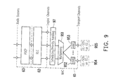
- FIG. 9 shows a Layer 2 uplink protocol stack structure for the case where only downlink transmission is supported on a secondary ROH cell.
- the heterogeneous carrier aggregation of the physical layers is exposed to the MAC layer for which at least one HARQ entity may be needed for a configured CC.
- one HARQ entity for each configured ROH cell for a UE may be needed.
- the MAC layer may be responsible for a joint scheduling for heterogeneous CC(s).
- the protocol stack illustrated in FIG. 9 can be executed by the communication protocol unit 56 of the wireless communication device 55, and may include at least a physical layer (not explicitly shown in FIG. 9 ), a MAC layer 61, a RLC layer 62 and a PDCP layer 63.
- a UL-SCH 954 on CC 1 may refer to a primary UL carrier component over a RCC
- a UL-SCH 955 on CC 2 may refer to a secondary UL carrier component over an RCC for the same UE.
- the MAC layer 61 there are HARQ entity 952 and HARQ entity 953 respectively for the primary CC 954 and the RCC 955.
- the communication protocol unit 56 could include a multiplexer 951 to multiplex MAC SDUs from one or different logical channels into transport blocks (TBs) delivered to the physical layers through their respective HARQ entity 952 and HARQ entity 953.
- a scheduling entity 97 exposed over the multiplexer 951 is configured for UL traffic scheduling/priority handling.
- the RLC layer 62 exposed over the MAC layer 61 could be configured for packet segmentation, ARQ and so forth.
- the PDCP layer 63 exposed over the RLC layer 62 could be configured for providing functions in security and ROHC.
- FIG. 10 shows a Layer 2 uplink protocol stack structure for the case uplink transmission is supported on a secondary ROH cell.
- the protocol stack illustrated in FIG. 10 can be executed by the communication protocol unit 56 of the wireless communication device 55, and can include at least a physical layer (not explicitly shown in FIG. 10 ), a MAC layer 61, a RLC layer 62 and a PDCP layer 63.
- a UL-SCH 1054 on CC 1 may refer to a primary UL carrier component over a RCC
- a UL-SCH 1055 on an Optical CC may refer to a secondary UL carrier component over an OCC for the same UE.
- the communication protocol unit 56 could include a multiplexer 1051 to multiplex MAC SDUs from one or different logical channels into transport blocks (TBs) delivered to the physical layers through their respective HARQ entity 1052 and HARQ entity 1053.
- a scheduling entity 1007 exposed over the multiplexer 1051 is configured for UL traffic scheduling/priority handling.
- the RLC layer 62 exposed over the MAC layer 61 could be configured for packet segmentation, ARQ and so forth.
- the PDCP layer 63 exposed over the RLC layer 62 could be configured for providing functions in security and ROHC.
- the HARQ entity illustrated in FIGs. 6-10 could be designed in physical (PHY) layer, for example in IEEE 802.16 specification, instead of being designed in the MAC layer as mentioned previously.
- PHY physical
- the aggregation of RCC(s), OCC(s), ACC(s) in the protocol stack can be below the MAC layer.
- FIG. 6B is a schematic diagram illustrating a Layer 2 protocol stack of a communication method for aggregation of heterogeneous carrier components according to an embodiment of the disclosure.
- Layer 2 Layer 2
- the Layer 2 may include the following sub-layers: Medium Access Control (MAC), Radio Link Control (RLC) and Packet Data Convergence Protocol (PDCP).
- MAC Medium Access Control
- RLC Radio Link Control
- PDCP Packet Data Convergence Protocol
- the heterogeneous carrier aggregation is exposed to the PDCP layer.
- the MAC protocol(s) and/or PHY protocol(s) for optical CC(s), such as IEEE 802.15.7 may be needed. The technical details may be performed in a manner similar to that illustrated in FIG. 6A .
- FIG. 6C is a schematic diagram illustrating a Layer 2 protocol stack of a communication method for aggregation of heterogeneous carrier components according to an embodiment of the disclosure.
- Layer 2 Layer 2
- the Layer 2 may include the following sub-layers: Medium Access Control (MAC), Radio Link Control (RLC) and Packet Data Convergence Protocol (PDCP).
- MAC Medium Access Control
- RLC Radio Link Control
- PDCP Packet Data Convergence Protocol
- the heterogeneous carrier aggregation is exposed to the RLC layer.
- the MAC protocol(s) and/or the PHY protocol(s) for optical CC(s), such as IEEE 802.15.7 may be needed. The technical details may be performed in a manner similar to that illustrated in FIG. 6A .
- FIG. 11 is a schematic diagram illustrating physical channel processing for communication based on visible light communication (VLC).
- VLC visible light communication
- the physical channel processing illustrated in FIG. 11 may be performed in physical layer(s).
- an upper portion of FIG. 11 is the transmitter using the VLC technique to communicate with the receiver illustrated on lower portion of FIG. 11 .
- Signal processing in digital domain is on the left hand side of a dashed line in FIG.
- the receiver uses filter lens unit 1111 to filter signal outside a preconfigured VLC bandwidth, and a photodiode (PD) 1112 receives the VLC signal and then generates analog signal (which includes AC portion and DC portion).
- a Trans-impedance amplifier (TIA) 1113 receives the analog signal from the PD 1112, and then generates the AC signal.
- the filter 1114 further filters out noise in the AC signal, and a DAC 1115 converts the analog signal to digital signal.
- the digital signal from the DAC 1115 is further processed by a baseband processing unit 1116 and recovered to be data source 1117 at the receiver.
- FIG. 12 shows an example of a frame structure for optical component carrier OCC according to an exemplary embodiment.
- one radio frame or one OCC frame 12 can be allocated with a frame duration of 10 ms.
- each 10 ms radio frame may be divided into ten of equally sized sub-frames such as a sub-frame 120 includes slot 120-0 and slot 120-1.
- Each sub-frame may consist of two equally sized slots 120-0 and 120-1. Slots 120-0, 120-1, 120-2, .., 120-18 and 120-19 may be available for DL/UL transmission in each 10 ms interval.
- the physical channels of OCC may include at least one of the following channels: synchronization channel (SCH), Physical downlink control channel (PDCCH), and Physical downlink shared channel (PDSCH).
- the SCH may be used by a UE for DL timing synchronization and is optional in this embodiment.
- the PDCCH may inform the UE about the resource allocation for DL assignment and/or UL grants, and/or Hybrid ARQ information related to UL traffic.
- the PDSCH may be used to carry the DL traffic (DL-SCH).
- the PDCCH for the OCC may not be needed if cross-layer scheduling is supported in both the base station and the UE.
- FIG. 13 illustrates a control-plane protocol stack for the case in which ROH is connected with an eNodeB by using power line communication (PLC).
- PLC power line communication
- this exemplary embodiment illustrates a UE 1301 communicating with a ROH device 1302 through VLC, the ROH device 1302 communicating with an eNodeB (or eNB) 1303 through power line communication technology (PLC), and the eNodeB 1303 communicating with the UE 1301 through radio communication technology.
- the eNodeB 1303 may be connected with the MME/S-GW 1304 through the S1 interface.
- the protocol stack shown on the lower portion of FIG. 13 further illustrates the control-plane protocol stack for the case in which the ROH device 1302 communicates with the eNodeB 1303 through PLC.
- the UE 1301 includes a non-access stratum (NAS) layer 1311, a radio resource control (RRC) layer 1312, a PDCP layer 1313, a RLC layer 1314, a MAC layer 1315 and a PHY layer 1316.
- the UE 1301 includes a radio module 1317 and a VLC module 1318, which may be separated by different HARQ entities.
- the eNodeB 1303 includes the RRC layer 1331, the PDCP layer 1332, the RLC layer 1333, the MAC layer 1334 and the PHY layer 1335.
- the eNodeB 1303 includes a radio module 1337 and a PLC module 1336, which may be separated by different HARQ entities.
- the UE 1301 communicates with the eNodeB 1303 through the radio module 1317 and the radio module 1337.
- the eNodeB 1303 communicates with the ROH device 1302 through the PLC module 1336 and the PLC module 1322.
- the UE 1301 communicates with the ROH device 1302 through the VLC module 1318 and the VLC module 1321.
- the communication link between the UE 1301 and the ROH device 1302 may be unidirectional or bidirectional.
- the NAS layer 1311 of the UE 1301 corresponds to an NAS layer 1341 of the MME/S-GW 1304.
- the RRC layer 1312, the PDCP layer 1313, the RLC layer 1314, the MAC layer 1315 and the PHY layer 1316 respectively correspond to the RRC layer 1331, the PDCP layer 1332, the RLC layer 1333, the MAC layer 1334 and the PHY layer 1335.
- FIG. 14 illustrates a user-plane protocol stack for the case in which ROH is connected with the eNodeB by using power line communication (PLC).
- PLC power line communication
- the UE 1301 communicates with the ROH device 1302 through VLC
- the ROH device 1302 communicates with the eNodeB (or eNB) 1303 through PLC
- the eNodeB 1303 communicates with the UE 1301 through radio communication technology.
- the protocol stack shown on the lower portion of FIG. 14 further illustrates the user-plane protocol stack for the case in which the ROH device 1302 communicates with the eNodeB 1303 through PLC.
- the UE 1301 includes the PDCP layer 1313, the RLC layer 1314, the MAC layer 1315 and the PHY layer 1316.
- the UE 1301 includes the radio module 1317 and the VLC module 1318, which may be separated by different HARQ entities.
- the eNodeB 1303 includes the PDCP layer 1332, the RLC layer 1333, the MAC layer 1334 and the PHY layer 1335.
- the eNodeB 1303 includes the radio module 1337 and the PLC module 1336, which may be separated by different HARQ entities.
- the UE 1301 communicates with the eNodeB 1303 through the radio module 1317 and the radio module 1337.
- the eNodeB 1303 communicates with the ROH device 1302 through the PLC module 1336 and the PLC module 1322.
- the UE 1301 communicates with the ROH device 1302 through the VLC module 1318 and the VLC module 1321.
- the communication link between the UE 1301 and the ROH device 1302 may be unidirectional or bidirectional.
- the PDCP layer 1313, the RLC layer 1314, the MAC layer 1315 and the PHY layer 1316 respectively correspond to the PDCP layer 1332, the RLC layer 1333, the MAC layer 1334 and the PHY layer 1335.
- FIG. 15 illustrates a DL transmission on SCC from an ROH to a UE with the UE feedback HARQ for the DL data from the SCC by using the PCC according to an exemplary embodiment.
- the communication network represented by the eNB 1303 may send data to the ROH by using wired line (e.g., an optical fiber, PLC), and then the ROH may forward the data to the UE by SCC (e.g., by using visible light communication).
- the UE may feedback the HARQ ACK/NACK for the DL data received from the SCC by using the PCC (e.g., transmitting the HARQ ACK/NACK for the SCC over a RCC such as LTE carrier).
- SCC may provide UL resources for UL transmission.
- the UE may transmit UL data through the SCC (e.g., by using visible light communication), and the communication network may feedback the HARQ ACK/NACK for the UL data through the PCC or the SCC.
- FIG. 16 is a schematic diagram illustrating a communication system based on aggregation of radio component carrier(s) and optical component carrier(s) according to a first exemplary embodiment.
- FIG. 16 illustrates a communication system with aggregation of Radio CC(s) and Optical CC(s) in a house.
- the communication system includes a macro eNodeB (eNB) 160 connected to a MME/S-GW 161 with a S1 interface, and a home eNodeB gateway (HeNB GW) 162 is also connected to a MME/S-GW 161 with a S1 interface.
- Multiple homes such as homes 163, 164, 165, 166 are connected to the HeNB GW 162, and the home 163 is within wireless service coverage area of the eNB 160.
- a HeNB 163-1 and one or more ROHs are deployed in the house 163.
- the ROHs are equipped with PLC communication modules and VLC communication modules.
- the house 163 is merely used as an example for explanation and is not intended to limit the present disclosure.
- the HeNB 163-1 is connected to the HeNB GW 162 through the S1 interface, and is also connected to ROH devices 163-2, 163-3, 163-4, 163-5, 163-6 through power-line communication (PLC).
- PLC power-line communication
- the HeNB 163-1 may provide at least a LTE carrier, and ROH devices 163-2, 163-3, 163-4, 163-5, 163-6 may provide Optical CCs for home users, and are controlled by the HeNB 163-1 through PLC.
- a UE 163-8 may receive OCC from the ROH device 163-3 or receive RCC from the macro eNodeB 160.
- a UE 163-7 may receive OCC from the ROH device 163-2 or receive RCC from the macro eNodeB 160.
- a UE 163-9 or UE 163-10 may receive OCC from the ROH devices 163-4, 163-5, 163-6 or receive RCC from the macro eNodeB 160 or the HeNB 163-1. Since visible light can be effectively blocked by walls or construction materials of the house 163, interference on OCC(s) from different ROH devices in different rooms can be effectively reduced. In addition, OCC(s) from ROH devices can also effectively increase bandwidth of the UE(s), and effectively reduce power consumptions on radio signal transmission and/or radio signal processing.
- a home user may buy an advanced HeNB 163-1, which may provide at least a LTE cell, and this cell may act as the Primary Cell (PCell) for a UE.
- This HeNB 163-1 may provide both DL carriers and UL carriers by using FDD or TDD.
- the HeNB 163-1 may automatically discover/search available ROH devices 163-2, 163-3, 163-4, 163-5, 163-6 in the house 163.
- the HeNB 163-1 may aggregate these ROHs 163-2, 163-3, 163-4, 163-5, 163-6 to provide SCell(s). These SCells may provide only DL transmission.
- the HeNB 163-1 may control and coordinate ROH(s) by using PLC.
- the eNB 160 or the HeNB 163-1 may have similar component elements and similar functionality as the base station 50.
- the UEs 163-8, 163-9, 163-10 may have similar component elements and similar functionality as the wireless communication device 55.
- FIG. 17 is a flowchart illustrating operation procedures for a communication method for aggregation of heterogeneous component carriers. It is noted that these steps do NOT need to be performed in the following order.
- the communication method for aggregation of heterogeneous component carriers includes operation procedures S171-S175.
- ROH device or HeNB performs discovery and initialization.
- an eNB may discover/search available ROHs (in the house), or ROH may discover/search HeNB. There are proposed three methods for discovering available ROHs described as below.
- the first method of discovering available ROHs is by using power line communication (PLC).
- FIG. 18 illustrates a method for discovering available ROHs according to the first exemplary embodiment.
- the HeNB may broadcast a ROH_discovery signalling (e.g., by using PLC).
- the ROH 1302 may reply a ROH_description information (or ROH_description message) to the HeNB (or the eNB 1303) by using PLC.
- the Simple Service Discovery Protocol (SSDP) may be used to discover HeNB and/or ROH.
- the ROH_discovery message may include the HeNB information (e.g., IP address) for ROH(s) to reply the ROH_description.
- the ROH_description message may include the ROH information (e.g., IP address) for the HeNB to control the ROH(s).
- the second method of discovering available ROHs is UE-assist discovering available ROHs.
- the HeNB may send ROH_discovery signalling (e.g., by using PLC).
- the ROH may broadcast ROH_description information (e.g., by visible light).
- UEs may forward the received ROH_description information to the HeNB.
- FIG. 19 illustrates another method for discovering available ROHs according to the first exemplary embodiment.
- the eNB 1303 firstly transmit the ROH_discovery signalling on PLC, the ROH 1302 broadcasts ROH_description information on its OCC in response to receiving the ROH_discovery signalling, the UE 1301 receives ROH_description information broadcasted on OCC through VLC from the ROH 1302, and finally forwards the ROH information regarding the ROH 1302 to the eNB 1303 on LTE carrier.
- the third method of discovering available ROHs is by Manual Settings.
- Home users may manually provide the information of the HeNB for the ROH to find the HeNB, and/or the home users may manually provide the information of ROHs for the HeNB to control these ROHs.
- ROHs may advertise itself to the HeNB (if there exists any HeNB), for example, when the ROH is added into the house. There are proposed three methods of discovering the eNB described below.
- the first method of discovering the eNB is by using power line communication (PLC).
- PLC power line communication
- the ROH may advertise a message including ROH_description information to the HeNB.
- the ROH_description message may include the ROH information (e.g., IP address) for the HeNB to control the ROH(s).
- the Simple Service Discovery Protocol (SSDP) may be used to discover HeNB.
- the second method of discovering the eNB is UE-assist discovering the HeNB.
- the ROH may broadcast ROH_description information (e.g., by visible light). Then, UEs may forward the received ROH_description information to the HeNB.
- the third method of discovering the eNB is Manual Settings.
- Home users may manually provide the information of the HeNB for the ROH to find the HeNB, and/or the home users may manually provide the information of ROHs for the HeNB to control these ROHs.
- the HeNB may control and/or coordinate the ROH(s) to transmit some reference signalling (e.g., through visible light).
- the reference signalling may be used for UE measurement.
- the reference signalling may be used for synchronization.
- a communication network configures the ROH(s) to the UE.
- the communication network may send a message to add (or configure) one or more OCCs to a UE.
- the network e.g., HeNB
- the measurement reports about the channel quality of the ROH feedback from the UE to the HeNB can be periodic or aperiodic.
- the UE may send a message to the HeNB to request for adding the ROH.
- the ROH may be selected by the user manually.
- the communication network e.g., HeNB
- This message may include the system information of the ROH, such as carrier frequency, bandwidth, cell identity, and so forth.
- the HeNB 163-1 can firstly determine the location of the UE 163-7, then determine that the UE 163-7 is closed to the location of the ROH device 163-2, and finally determine to configure the ROH device 163-2 to the UE 163-7.
- the same configuration principle can be applied based on other criteria.
- the UE performs measurements.
- UE may measure and report the channel qualities for OCC(s).
- a UE may measure channel quality for each of OCC(s), and report the measured channel quality to the HeNB or the eNB.
- the ROH(s) may send some reference signalling (e.g., common reference signal (CRS), UE-specific reference signal, DMRS, pilots, and so like.).
- the UE may measure the signal strength (e.g., reference signal received power (RSRP), reference signal received quality (RSRQ), and so forth) of ROH(s), and report the measurement results to the communication network (e.g., HeNB).
- the measurement results may be reported periodically or when a certain event is triggered.
- the measurement report may include the signal strength (e.g., RSRP, RSRQ) measured on OCC(s) from the ROH(s).
- the communication network (such as the eNodeB) activates the ROH(s) for the UE.
- the communication network may determine to activate the configured OCC(s). Activation/deactivation mechanism of SCells may be supported to save UE battery consumption.
- the communication network may activate and/or deactivate the SCell(s) by sending the Activation/Deactivation MAC control element.
- the UE may activate the SCell including: sounding reference signal (SRS) transmissions on the SCell; channel state information (CSI), such as channel quality indictor/pre-coding matrix indicator/ranking indicator/ Precoding Type Indicator (CQI/PMI/RI/PTI), reporting for the SCell; PDCCH monitoring for the SCell; a start or a restart of the sCellDeactivationTimer associated with the SCell.
- SRS sounding reference signal
- CSI channel state information
- CQI/PMI/RI/PTI Precoding Type Indicator
- the sCellDeactivationTimer associated with the SCell can be 320 ms.
- the UE may deactivate the SCell; stop the sCellDeactivationTimer associated with the SCell; flush all HARQ buffers associated with the SCell.
- the Activation/Deactivation MAC control element associated with the SCell may be a MAC message.
- the UE may not to transmit SRS for the SCell; not to report channel state information (e.g., CQI/PMI/RI/PTI) for the SCell; not to transmit on UL-SCH for the SCell; not to monitor the PDCCH for the SCell.
- channel state information e.g., CQI/PMI/RI/PTI
- the communication network deactivates/de-configures the ROH(s) for the UE.
- the communication network e.g., HeNB
- the HeNB may send the Activation/Deactivation MAC control element to deactivate the OCC(s), and/or send a message (e.g., RRCConnectionReconfiguration message) to de-configure the OCC(s) for the UE.
- a message e.g., RRCConnectionReconfiguration message
- FIG. 20 is a schematic diagram illustrating a communication system based on aggregation of radio component carrier(s) and acoustic component carrier(s) according to a second exemplary embodiment.
- a RAH which provides at least an Acoustic Component Carrier (e.g., by using sonar) is deployed.
- the RAH may be controlled by an eNB or a gateway by using wireless or wired-line communication.
- This second exemplary embodiment can be used in health-care application. Referring to FIG.
- an eNB 160 is connected to a MME/S-GW 161 through the S1 interface
- an remote acoustic head (RAH) device 200-2 deployed under water is also connected to a MME/S-GW 161 through the S1 interface
- the eNB 160 may be connected to the RAH device 200-2 (by wired or wireless communication link).
- a satellite 200-1 is connected with the MME/S-GW 161 by wireless communication link.
- the RAH device 200-2 may be controlled by the eNB 160 or a gateway device (such as the MME/S-GW 161) by using wireless communication link or wired-line communication.
- the eNB 160 and the RAH device 200-2 may be in different locations.
- a user 200-3 equipped with corresponding component carrier transmitting/receiving means, may communication with the eNB 160 on RCC(s) (e.g., LTE carrier) of the eNB 160, or communicate with the satellite 200-1 on RCC(s) of the satellite 200-1, or communication with the RAH device 200-2 on ACC(s) of the RAH device 200-2.
- a boat 200-4 equipped with corresponding component carrier transmitting/receiving means, may communication with the eNB 160 on RCC(s) of the eNB 160, or communicate with the satellite 200-1 on RCC(s) of the satellite 200-1, or communication with the RAH device 200-2 on ACC(s) of the RAH device 200-2.
- a submarine 200-5 equipped with corresponding component carrier transmitting/receiving means, may communication with the RAH device 200-2 on ACC(s) of the RAH device 200-2.
- the communication between the RAH device 200-2 and the user 200-3 may be bidirectional or unidirectional (in a embodiment, only the RAH device 200-2 transmits information on the ACC(s) to the user 200-3, or only the user 200-3 transmits information on the ACC(s) to the RAH device 200-2).
- the same operation principle can be applied to the communication between the RAH device 200-2 and the boat 200-4, and the communication between the RAH device 200-2 and the submarine 200-5.
- the eNB 160 has similar component elements and similar functionality as the base station 50.
- the component carrier transmitting/receiving means on the user 200-3, or the boat 200-4 or the submarine 200-5 can have similar component elements and similar functionality as the wireless communication device 55.
- FIG. 21 is a flowchart illustrating a communication method involved with carrier aggregation with heterogeneous component carriers according to an embodiment of the disclosure.
- the proposed communication method for aggregation with heterogeneous component carriers is adapted to a wireless communication station, where the wireless communication station may be a base station, a Node-B, an eNodeB, a base transceiver system, a remote head device, an access point, a home base station, a femto-cell base station, a relay station, a scatterer, a repeater, an intermediate node, an intermediary, or a satellite-based communication base station.
- the wireless communication station is, for example, a base station 50 and the proposed method includes following procedures: the communication protocol unit 51 of the base station 50 aggregates physical channel resources respectively corresponding to heterogeneous access technologies in a Layer 2 or below the Layer 2 in a protocol stack (step S2101); the communication protocol unit 51 communicates with at least one wireless terminal communication device (for example the wireless communication device 55, as shown in FIG. 5B ) through the physical channel resources respectively corresponding to the heterogeneous access technologies (e.g., according to at least channel conditions of the physical channel resources (step S2102)).
- the communication protocol unit 51 of the base station 50 aggregates physical channel resources respectively corresponding to heterogeneous access technologies in a Layer 2 or below the Layer 2 in a protocol stack (step S2101); the communication protocol unit 51 communicates with at least one wireless terminal communication device (for example the wireless communication device 55, as shown in FIG. 5B ) through the physical channel resources respectively corresponding to the heterogeneous access technologies (e.g., according to at least channel conditions of the physical channel resources
- the step of aggregating the physical channel resources respectively corresponding to the heterogeneous access technologies in the Layer 2 or below the Layer 2 in the protocol stack includes the communication protocol unit 51 assigns at least one HARQ entity for each of configured heterogeneous component carriers.
- the physical channel resources respectively corresponding to heterogeneous access technologies are heterogeneous component carriers.
- FIG. 22 is a flowchart illustrating another communication method involved with carrier aggregation with heterogeneous component carriers according to an embodiment of the disclosure.
- the proposed communication method for aggregation with heterogeneous component carriers is adapted to a UE, and includes following procedures: the communication protocol unit 56 of the wireless communication device 55 receives a message from a base station (for example the base station 50, as shown in FIG.
- step S2201 the communication protocol unit 56 aggregates physical channel resources respectively corresponding to heterogeneous access technologies in a Layer 2 or below the Layer 2 in a protocol stack according to the message (step S2202); the communication protocol unit 56 receives another message from the base station (step S2203); the communication protocol unit 56 activates the physical channel resources according to the another message (step S2204).
- activating the physical channel resources by the communication protocol unit 56 may refer to transmitting uplink data, transmitting uplink message or receiving downlink data or receiving downlink message over activated physical channel resources.
- activating the physical channel resources may include: sounding reference signal (SRS) transmissions on the physical channel resources, or CSI (e.g., CQI/PMI/RI/PTI) reporting for the physical channel resources, or PDCCH monitoring for the physical channel resources, or a start or a restart of the sCellDeactivationTimer associated with the physical channel resources.
- SRS sounding reference signal
- CSI e.g., CQI/PMI/RI/PTI
- the exemplary embodiments of the disclosure communication methods for aggregation of heterogeneous component carriers are proposed along with communication devices and remote head devices and base stations using the same methods.
- the exemplary embodiments provide a simple communication system or a simple protocol stack or communication methods to aggregate heterogeneous component carriers in the Layer 2 or below the Layer 2, and effectively increase bandwidth of the wireless transmission.
- the proposed communication methods for aggregation of heterogeneous component carriers can be deployed with remote head devices.
Landscapes
- Engineering & Computer Science (AREA)
- Signal Processing (AREA)
- Computer Networks & Wireless Communication (AREA)
- Mobile Radio Communication Systems (AREA)
Abstract
Description
- The disclosure generally relates to communication methods for aggregation of heterogeneous component carriers and communication devices and wireless communication stations using the same methods.
- In order to provide higher data rate transmissions and to support various applications, communication service providers are continually developing improvements to existing communication networks. Wider bandwidth allocation is a way to achieve the targets. So far, more and more techniques have been presented to achieve wireless communication, such as radio communication (e.g., UMTS, HSPA+, LTE, LTE-Advanced, WiMAX, WiFi, Zigbee, Bluetooth, etc.), light communication (e.g., Visible Light Communication (VLC)), sound communication (e.g., Sonar), infrared communications, and so forth. Therefore, it is important to integrate these heterogeneous communication technologies together so as to provide a wider bandwidth and/or to provide a higher data rate for mobile users.
- A communication method for aggregation of heterogeneous component carriers is introduced herein. According to an exemplary embodiment, the communication methods for aggregation of heterogeneous component carriers is adapted to a wireless communication station and includes following steps: aggregating physical channel resources respectively corresponding to heterogeneous access technologies in a
Layer 2 or below theLayer 2 in a protocol stack; and communicating with at least one wireless terminal communication device through the physical channel resources respectively corresponding to the heterogeneous access technologies, wherein the physical channel resources respectively corresponding to heterogeneous access technologies are heterogeneous component carriers. - A wireless communication station is introduced herein. According to an exemplary embodiment, the wireless communication station includes at least one physical communication unit and a communication protocol unit. The at least one physical communication unit is configured for communicating with at least one wireless terminal communication device through at least one physical channel resource. The communication protocol unit is connected to the at least one physical communication unit, configured for aggregating the physical channel resources respectively corresponding to heterogeneous access technologies in a
Layer 2 or below theLayer 2 in a protocol stack, wherein the physical channel resources respectively corresponding to the heterogeneous access technologies are heterogeneous component carriers. - A communication method for aggregation of heterogeneous component carriers is introduced herein. According to an exemplary embodiment, the communication method for aggregation of heterogeneous component carriers is adapted for a communication device, and includes following steps: aggregating physical channel resources respectively corresponding to heterogeneous access technologies in a
Layer 2 or below theLayer 2 in a protocol stack; and communicating with at least one wireless communication station through the physical channel resources respectively corresponding to the heterogeneous access technologies. - A communication device is introduced herein. According to an exemplary embodiment, the communication device includes at least one physical communication unit and a communication protocol unit. The at least one physical communication unit is configured for communicating with at least one wireless communication station through at least one physical channel resource. The communication protocol unit is connected to the at least one physical communication unit, and configured for aggregating physical channel resources respectively corresponding to heterogeneous access technologies in a
Layer 2 or below theLayer 2 in a protocol stack, wherein the physical channel resources respectively corresponding to heterogeneous access technologies are heterogeneous component carriers. - Several exemplary embodiments accompanied with figures are described in detail below to further describe the disclosure in details.
- The accompanying drawings are included to provide further understanding, and are incorporated in and constitute a part of this specification. The drawings illustrate exemplary embodiments and, together with the description, serve to explain the principles of the disclosure.
-
FIG. 1 is a schematic diagram illustrating communication methods involved with carrier aggregation with heterogeneous component carriers according to an embodiment of the disclosure. -
FIG. 2 is a schematic diagram illustrating a communication network utilizing aggregation of heterogeneous carrier components according to an embodiment of the disclosure. -
FIG. 3 is a schematic diagram illustrating a communication network utilizing aggregation of heterogeneous carrier components according to an embodiment of the disclosure. -
FIG. 4 illustrates a system architecture of a communication network utilizing aggregation of heterogeneous carrier components. -
FIG. 5A is a functional block diagram illustrating a base station according to an exemplary embodiment. -
FIG. 5B is a functional block diagram illustrating a wireless communication device according to an exemplary embodiment. -
FIG. 6A is a schematic diagram illustrating aLayer 2 protocol stack of a communication method for aggregation of heterogeneous carrier components according to an embodiment of the disclosure. -
FIG. 6B is a schematic diagram illustrating aLayer 2 protocol stack of a communication method for aggregation of heterogeneous carrier components according to an embodiment of the disclosure. -
FIG. 6C is a schematic diagram illustrating aLayer 2 protocol stack of a communication method for aggregation of heterogeneous carrier components according to an embodiment of the disclosure. -
FIG. 7 is a schematic diagram illustrating aLayer 2 protocol stack for downlink multicast/broadcast on optical carrier component according to an embodiment of the disclosure. -
FIG. 8 is a schematic diagram illustrating aLayer 2 protocol stack of a communication method for supporting unicast service(s) on RCC(s) and supporting MBMS on OCC according to an embodiment of the disclosure. -
FIG. 9 shows aLayer 2 uplink protocol stack structure for the case where only downlink transmission is supported on a secondary ROH cell. -
FIG. 10 shows aLayer 2 uplink protocol stack structure for the case uplink transmission is supported on a secondary ROH cell. -
FIG. 11 is a schematic diagram illustrating physical channel processing for communication based on visible light communication (VLC). -
FIG. 12 shows an example of a frame structure for optical component carrier OCC according to an exemplary embodiment. -
FIG. 13 illustrates a control-plane protocol stack for the case in which a remote optical head device is connected with an eNodeB by using power line communication. -
FIG. 14 illustrates a user-plane protocol stack for the case in which remote optical head device is connected with the eNodeB by using power line communication. -
FIG. 15 illustrates downlink transmission on secondary component carrier from an ROH to a UE with the UE feedback HARQ for the downlink data from the secondary component carrier by using the primary component carrier according to an exemplary embodiment. -
FIG. 16 is a schematic diagram illustrating a communication system based on aggregation of radio component carrier(s) and optical component carrier(s) according to a first exemplary embodiment. -
FIG. 17 is a flowchart illustrating operation procedures for a communication method for aggregation of heterogeneous component carriers. -
FIG. 18 illustrates a method for discovering available ROHs according to the first exemplary embodiment. -
FIG. 19 illustrates another method for discovering available ROHs according to the first exemplary embodiment. -
FIG. 20 is a schematic diagram illustrating a communication system based on aggregation of radio component carrier(s) and acoustic component carrier(s) according to a second exemplary embodiment. -
FIG. 21 is a flowchart illustrating a communication method involved with carrier aggregation with heterogeneous component carriers according to an embodiment of the disclosure. -
FIG. 22 is a flowchart illustrating another communication method involved with carrier aggregation with heterogeneous component carriers according to an embodiment of the disclosure. - Some embodiments of the present application will now be described more fully hereinafter with reference to the accompanying drawings, in which some, but not all embodiments of the application are shown. Indeed, various embodiments of the application may be embodied in many different forms and should not be construed as limited to the embodiments set forth herein; rather, these embodiments are provided so that this disclosure will satisfy applicable legal requirements. Like reference numerals refer to like elements throughout.
- In the present disclosure, methods and apparatus to integrate heterogeneous wireless communication techniques are presented. In other words, communication methods for aggregation of heterogeneous component carriers are proposed along with wireless terminal communication devices, wireless remote head devices and wireless communication stations (e.g., bases station devices). More details can be found in the following sections. It can be shown that the proposed communication methods for aggregation of heterogeneous component carriers is rather simple than complex, and can still achieve expected performance in terms of providing wider bandwidth to the wireless terminal communication devices. It is noted that third generation project partnership (3GPP)-like technical terms are used to present major ideas in the present disclosure; however, the proposed communication methods for aggregation of heterogeneous component carriers in this disclosure could be applied to any other wireless communication systems (e.g., IEEE 802.11, IEEE 802.16, WiMAX and so forth.).
- Throughout the disclosure, a user equipment (UE) could refer to a mobile station, an advanced mobile station, a wireless terminal communication device, an M2M device, a MTC device, and so fourth. The term "UE" in this disclosure may be, for example, a server, a client, a desktop computer, a laptop computer, a network computer, a workstation, a personal digital assistant (PDA), a tablet personal computer (PC), a scanner, a telephony device, a pager, a camera, a television, a hand-held video game device, a musical device, a media player device, a wireless sensor, and so forth. In some applications, a UE may be a fixed computing device operating in a mobile environment, such as a bus, a train, an airplane, a boat, a car, and so forth.
- In the present disclosure, the term "eNodeB" may be, for example, a base station (BS), a Node-B, an eNode B, a base transceiver system (BTS), a remote head device, an access point, a home base station, a femto-cell base station, a relay station, a scatterer, a repeater, an intermediate node, an intermediary, and/or a satellite-based communication base station, and so forth.
- In the present disclosure, the term "downlink" (DL) could refer to the RF signal transmission from a base station/a remote head device to a UE within the radio coverage of the base station; the term "uplink" (UL) could refer to the RF signal transmission from a UE to its access base station/remote head device.
- Besides, in this disclosure, the term CC could be used to represent a component carrier. However, a CC could also be considered as a cell in some technical literature or technical specifications, where a CC may be operated on frequency division duplex (FDD) and/or time division duplex (TDD). A cell may have downlink resource to transmit signals from a BS to a UE, and/or may have uplink resource to transmit signals from a UE to a BS. For example, the term "Primary CC "(or "PCC") may be equivalent to the term "Primary Cell (Pcell)", and the term "Secondary CC" ("SCC") may be equivalent to the term "Secondary Cell (Scell)".
- Multiple CCs may operate on the same frequency band or different frequency bands, and may have the same center frequency or different center frequencies. Multiple CCs may belong to the same eNodeB or different eNodeBs.
- The proposed communication methods for aggregation of heterogeneous component carriers (which may be different communication technologies) can be operated in a wireless communication environment are disclosed. The wireless communication system of aggregation of heterogeneous carriers may include a communication network equipped with at least two heterogeneous component carriers, a UE equipped with communication modules (including physical layer and its corresponding MAC layer) to aggregate at least two heterogeneous component carriers, and means for aggregating heterogeneous component carriers in a
Layer 2 or below theLayer 2. - 3GPP Long term evolution (abbreviated as LTE hereinafter) system is used for only an example in the present disclosure. In a LTE-Advanced system, carrier aggregation (abbreviated as CA hereinafter) is used to aggregate two or more LTE component carriers (CCs) originating from the same eNB in order to provide a wider transmission bandwidth. With carrier aggregation technique, communication networks may be enabled to operate over continuous carriers or discontinuous carriers having different bandwidths. Also, a UE can simultaneously receive or transmit on one CC or multiple CCs depending on its capabilities. For example, in a wireless service coverage of an eNB, some UEs with reception and transmission capabilities for CA may simultaneously receive and transmit on multiple CCs; while some UEs may receive and transmit on a single CC only.
- This disclosure presents a mechanism to achieve carrier aggregation with heterogeneous component carriers.
FIG. 1 is a schematic diagram illustrating communication methods involved with carrier aggregation with heterogeneous component carriers according to an embodiment of the disclosure. As shown inFIG.. 1 , the upper half protocol stack refers to the protocol stack layer at a base station (or an eNodeB) side, the communication network (e.g., eNodeB) may be equipped with heterogeneous component carriers (CCs). For example, it may be equipped with one or more radio component carriers (e.g., by using LTE carriers), one or more optical component carriers (e.g., by using visible light communication), and/or one or more acoustic component carriers, which may use sonar to achieve wireless communication. The present disclosure is not limited to radio component carriers, optical component carriers and acoustic component carriers, other communication technologies such as infrared component carriers can also be used in other embodiments. - Referring to
FIG. 1 , at the base station, in the physical layer, a radio component carrier (RCC) 113, an optical component carrier (OCC) 114 and an acoustic component carrier (ACC) 115 are aggregated in MAC layer (refers to MAC scheduling inFIG. 1 ) 112, and anetwork layer 111 is on top of theMAC layer 112. - Referring to
FIG. 1 , there are three users shown on the bottom half ofFIG. 1 .User 1 has only one RCC in the physical layer (referring to PHY RCC) 123, on top of theRCC 123 is aMAC layer 122, and on top of theMAC layer 122 is anetwork layer 121. The communication between the base station and theUser 1 can be through theRCC 113 andRCC 123. On the other hand,User 2 has oneRCC 133 and oneOCC 134 in the physical layer, on top of theRCC 133 and theOCC 134 is aMAC layer 132, and theMAC layer 132 aggregates theRCC 133 and oneOCC 134. On top of theMAC layer 132 is anetwork layer 131. The communication between the base station and theUser 2 can be through theRCC 113 andRCC 133, and/or through theOCC 114 andOCC 134. Similarly, User 3 has oneRCC 143 and oneACC 144 in the physical layer, on top of theRCC 143 and theACC 144 is aMAC layer 142, and theMAC layer 142 aggregates theRCC 143 and oneACC 144. On top of theMAC layer 142 is anetwork layer 141. The communication between the base station and the User 3 can be through theRCC 113 andRCC 143, and/or through theACC 115 andACC 144. - The communication network may configure a UE to aggregate two or more CCs with heterogeneous communication media based on the UE capability. For example, the UE may provide its UE capability information to the communication network(s) to indicate the support of aggregation of heterogeneous component carriers. Based on the UE capability information, the communication network may determine to configure UE with two CCs. One is radio component carrier (RCC), and the other is optical component carrier (OCC). The UE may simultaneously receive and/or transmit through these heterogeneous CCs based on its capabilities.
-
FIG. 2 is a schematic diagram illustrating a communication network utilizing aggregation of heterogeneous carrier components according to an embodiment of the disclosure. Referring toFIG. 2 , in acommunication network 20, abase station 21 could be connected to remote head devices at the same cell site, such asROH 213 andRRH 212 being deployed at the same cell site. Thebase station 21 could be connected to other remote head devices deployed in different physical location such as aRAH 211 being deployed in a different cell site than that of theROH 213. Also, in the present embodiment, anotherstation 22 is connected to remote head devices at the same cell site such asRAH 222 andRRH 223 being deployed at the same cell site. It is noted that thebase station -
FIG. 3 is a schematic diagram illustrating a communication network utilizing aggregation of heterogeneous carrier components according to an embodiment of the disclosure. Referring toFIG. 3 , in a communication network, within a wireless coverage area (denoted as a macro cell 300) of abase station 31, there are deployed anRRH 32, anROH 33, anRAH 34, an ROH 35 (also called a "Light cell") and anRRH 36. There are also someUEs macro cell 300. Thebase station 31 can connect to theRRH 32, theROH 33, theRAH 34, theROH 35 and theRRH 36. TheUE 38 is within a wireless service coverage area of theROH 35, and theUE 39 is within a radio service coverage area of theRRH 36. - In the present embodiment, one of the CCs configured by the communication network to the UE may be designated as a Primary CC (also called a PCC or a PCell), and the other CCs are secondary CC(s) (also called SCC(s) or SCell(s)). For example, the network may configure an "LTE Cell" (such as the macro cell 300) as a PCell, and configure a "Light Cell" (such as the ROH 35) as a SCell. In some embodiments, the PCell may provide the resource allocation information (e.g., PDCCH) for downlink (DL) assignment and/or uplink (UL) bandwidth grants (UL grants) for SCell. As such, the control channel overhead can be saved for the SCell(s).
- In addition, the communication media used by SCC may only provide a unidirectional transmission (i.e., from the communication network to a UE or from a UE to a communication network). For example, in some embodiments, only downlink transmission is allowed in OCC. As for the hybrid automatic repeated request (HARQ) acknowledgement/negative acknowledgement (ACK/NACK) feedbacks, the ACK/NACK feedbacks for SCell DL transmission can be sent through its corresponding PCell. For example, HARQ ACK/NACK feedbacks for DL transmission in an OCC may be sent by the UE through the RCC.
-
FIG. 4 illustrates a system architecture of a communication network utilizing aggregation of heterogeneous carrier components. Referring toFIG. 4 , acommunication network 40 includes at least a mobility management entity (MME)/serving gateway (S-GW) 412, a MME/S-GW 414, aneNodeB 421, aneNodeB 422, anRRH 431, anROH 441, anROH 442 and anRAH 451. UE is not shown inFIG. 4 , but UE can access to thecommunication network 40 through CC(s) with theeNodeB 421, theeNodeB 422, theRRH 431, theROH 441, theROH 442 or theRAH 451. - In some embodiments, heterogeneous transmission points (e.g., the
eNodeB 421, theRRH 431, theRAH 451, theROH 441 and so forth) may be located at the same location or within the same device (e.g., equipped by the same eNodeB). For example, an eNodeB may have both ROH capability and RRH capability. In other embodiments, heterogeneous transmission points may be connected by wired lines (e.g., by an optical fiber, a power line, a coaxial cable and so forth) and/or be connected by using an X2 interface. InFIG. 4 , theeNodeB 421, theeNodeB 422, theRRH 431, theROH 441, theROH 442 and theRAH 451 are connected with neighboring heterogeneous transmission points by using the X2 interface. In these cases, several wired-line communication protocols (e.g., ITU G.hn (ITU G.9960), IEEE P1901, HomePlug AV, MediaXtream, HPNA (ITU G.9954)) may be applied. Further, heterogeneous transmission points (e.g., theeNodeB 421, theeNodeB 422 or the ROH 441) may communicate with gateways (e.g., the MME/S-GW 412, 414) by using an S1 interface. That is, theeNodeB 421 and theeNodeB 422 may communicate with the gateways by using the S1 interface. -
FIG. 5A is a functional block diagram illustrating a wireless communication station (e.g., a base station) according to an exemplary embodiment. Referring toFIG. 5A , abase station 50 may include at least acommunication protocol unit 51, aphysical communication unit 521, ..., aphysical communication unit 52n, and anetwork interface 53. For example, thephysical communication unit 521, ..., aphysical communication unit 52n may be aradio communication unit 521, an optical communication unit 522, and/or an acoustic communication unit 523, and so like. Thephysical communication unit 521, ..., and thephysical communication unit 52n are configured for providing corresponding wireless access carrier components for communicating with remote head device(s) and UE(s) within the wireless service coverage area of thebase station 50. - In practical implementation, each of the
physical communication unit 521, ..., and thephysical communication unit 52n could be a transceiver circuit which is connected to its corresponding (not shown inFIG. 5A ) wireless transceiving means (such as an antenna, an optical signal transmitter or an optical signal receiver, or an acoustic signal transmitter or an acoustic signal receiver). Also, the transceiver circuit in each of thephysical communication unit 521, ..., aphysical communication unit 52n could be configured for performing analog-to-digital signal conversion, digital-to-analog signal conversion, modulation, demodulation, signal amplification, low pass filtering, band pass filtering, and so forth. Further, the transceiver circuit provides the received message (converted from radio signals transmitting by wireless communication devices) to thecommunication protocol unit 51, modulates the message fromcommunication protocol unit 51 into modulated radio signals, and further transmits the modulated radio signals to the wireless communication device(s) over its corresponding carrier component. - Referring to
FIG. 5A , the wireless communication station (e.g., base station 50) including at least thecommunication protocol unit 51, thephysical communication unit 521, ..., thephysical communication unit 52n, and thenetwork interface 53, could include a wireless communication protocol stack, having communication protocol stack software units which may operate in a Layer 1 (physical layer), Layer 2 (L2), IP, UDP, GTP, SCTP, S1-AP, X2-AP, and so forth. Thenetwork interface 53 is connected to thecommunication protocol unit 51, and is configured for connecting thebase station 50 with other networking entities such as MME/S-GW, network controllers and other base stations or remote head device(s). - The
communication protocol unit 51 could include at least a processor unit (not shown inFIG. 5A ), and at least a communication protocol stack software (or communication protocol stack firmware). Each processor unit may include multiple processor cores, and when the processor unit executes communication protocol stack software (which includes instruction codes corresponding to procedures in the Layer 1 (physical layer), the Layer 2 (L2), IP, UDP, GTP, SCTP, S1-AP, X2-AP, and so forth), thecommunication protocol unit 51 could perform relevant procedures corresponding to the Layer 1 (physical layer), the Layer 2 (L2), IP, UDP, GTP, SCTP, S1-AP, X2-AP, and so forth. For example, thecommunication protocol unit 51 could perform related functions in aggregation of heterogeneous carrier components in theLayer 2 or below theLayer 2, and meanwhile thecommunication protocol unit 51 could further perform related procedures illustrated in followingFIGs. 6-20 . -
FIG. 5B is a functional block diagram illustrating a wireless communication device according to an exemplary embodiment. Referring toFIG. 5B , a wireless communication device 55 may include at least acommunication protocol unit 56, aphysical communication unit 571, ..., and aphysical communication unit 57n. For example, thephysical communication unit 571, ..., and thephysical communication unit 57n may be aradio communication unit 571, an optical communication unit 572, and/or an acoustic communication unit 573, and so like. Thephysical communication unit 571, ..., thephysical communication unit 57n are configured for providing corresponding wireless access carrier components for communicating with remote head device(s) or base station(s). - In practical implementation, each of the
physical communication unit 571, ..., thephysical communication unit 57n could be a transceiver circuit which is connected to its corresponding (not shown inFIG. 5B ) wireless transceiving means (such as an antenna, an optical signal transmitter or an optical signal receiver, or an acoustic signal transmitter or an acoustic signal receiver). Also, the transceiver circuit in each of thephysical communication unit 571, ..., thephysical communication unit 57n could be configured for performing analog-to-digital signal conversion, digital-to-analog signal conversion, modulation, demodulation, signal amplification, low pass filtering, band pass filtering, and so forth. Further, the transceiver circuit provides the received message (converted from radio signals transmitting by wireless communication network) to thecommunication protocol unit 56, modulates the message fromcommunication protocol unit 56 into modulated radio signals, and further transmits the modulated radio signals to the wireless communication device(s) over its corresponding carrier component. - Referring to
FIG. 5B , the wireless communication device 55 including thecommunication protocol unit 56,physical communication unit 571, ..., and thephysical communication unit 57n could include a wireless communication protocol stack, having communication protocol stack software units which may operate in a Layer 1 (physical layer), Layer 2 (L2), IP, UDP, GTP, SCTP, S1-AP, X2-AP, and so forth. - The
communication protocol unit 56 could include at least a processor unit (not shown inFIG. 5B ), and at least a communication protocol stack software (or communication protocol stack firmware). Each processor unit may include multiple processor cores, and when the processor unit executes communication protocol stack software (which includes instruction codes corresponding to procedures in Layer 1 (physical layer), Layer 2 (L2), IP, UDP, GTP, SCTP, S1-AP, X2-AP, and so forth), thecommunication protocol unit 56 could perform relevant procedures corresponding to the Layer 1 (physical layer), Layer 2 (L2), IP, UDP, GTP, SCTP, S1-AP, X2-AP, and so forth. For example, thecommunication protocol unit 56 could perform related functions in aggregation of heterogeneous carrier components in theLayer 2 or below theLayer 2, and meanwhile thecommunication protocol unit 56 could further perform related procedures illustrated in followingFIGs. 6-20 . -
FIG. 6A is a schematic diagram illustrating aLayer 2 protocol stack of a communication method for aggregation of heterogeneous carrier components according to an embodiment of the disclosure. An example of Layer 2 (L2) structure for DL with OCC configured can be seen fromFIG. 6A . TheLayer 2 may include the following sub-layers: Medium Access Control (MAC), Radio Link Control (RLC) and Packet Data Convergence Protocol (PDCP). Referring toFIG. 6A , in this embodiment, a secondary OCC is configured for a UE. As shown inFIG. 6A , the heterogeneous carrier aggregation of the physical layers is exposed to the MAC layer for which at least one HARQ entity may be needed for a configured CC. For example, one HARQ entity for each configured ROH cell for a UE may be needed. The MAC layer may be responsible for a joint scheduling for heterogeneous CC(s). - To be illustrated in more details, the protocol stack enclosed by a
reference number 65 is responsible for serving a first UE, and the protocol stack enclosed by areference number 66 is responsible for serving a second UE. The protocol stack can be executed by thecommunication protocol unit 51 of thebase station 50, and can include at least a physical layer (not explicitly shown inFIG. 6A ), aMAC layer 61, a radio link control (RLC)layer 62 and a packet data convergence protocol (PDCP)layer 63. For the first UE, a DL-shared channel (DL-SCH) 654 on CC1 may refer to a primary carrier component over a RCC, and a DL-SCH 655 on an optical CC may refer to a secondary carrier component over an OCC for the first UE. In the MAC layer, there areHARQ entity 652 andHARQ entity 653 respectively for theRCC 654 and theOCC 655. Thecommunication protocol unit 51 could include amultiplexer 651 to multiplex MAC SDUs from one or different logical channels into transport blocks (TBs) delivered to the physical layers through theirrespective HARQ entity 652 andHARQ entity 653. Aunicast scheduling entity 67 exposed over themultiplexer 651 is configured for unicast traffic scheduling/priority handling. TheRLC layer 62 exposed over theMAC layer 61 could be configured for packet segmentation, ARQ and so forth. ThePDCP layer 63 exposed over theRLC layer 62 could be configured for providing functions in security and ROHC. Similarly, the details of amultiplexer 661,HARQ entity 662 andHARQ entity 663, and aprimary CC 664 and theOCC 665 for the second UE may be referred to the previous descriptions for the first UE. -
FIG. 6A also illustrates radio bearers exposed over thePDCP layer 63, logical channels such as CCCH, BCCH and PCCH over theMAC layer 61, and transport channels such as BCH, PCH and MCH exposed below theMAC layer 61, but their detailed technical contents are not disclosed here since the major concept in the present disclosure is aggregation of heterogeneous carrier components in theLayer 2 or below theLayer 2. -
FIG. 6A also illustrates protocol stack for DL multicast/broadcast service(s). The protocol stack enclosed by areference number 68 is responsible for DL multicast/broadcast service(s).FIG. 7 is a schematic diagram illustrating aLayer 2 protocol stack for DL multicast/broadcast on optical carrier component according to an embodiment of the disclosure. An example of L2 structure to support Multimedia Broadcast Multicast Service (MBMS) on Optical CC is illustrated inFIG. 7 . Referring toFIG. 7 , a multicast channel (MCH) onoptical CC 683 is configured for providing broadcast and/or multicast traffic over OCC. AMBMS scheduling unit 681 is exposed below theRLC layer 62 and connected to theRLC layer 62 through logical channels MCCH and MTCH. TheMBMS scheduling unit 681 schedules DL multicast/broadcast traffic from the MCCH and MTCH, and amultiplexer 682 multiplexes the DL multicast/broadcast traffic from logical channels MCCH and MTCH into transport block(s) to the physical layers for theOCC 683. - An example of the
Layer 2 structure to support unicast service(s) on RCC, and support multicast and/or broadcast service(s) on OCC can be found inFIG. 8. FIG. 8 is a schematic diagram illustrating aLayer 2 protocol stack of a communication method for supporting unicast service(s) on RCC(s) and supporting multicast and/or broadcast service(s) on OCC according to an embodiment of the disclosure. For example, in the embodiment illustrated inFIG. 8 , the protocol stack enclosed by areference number 85 is responsible for serving a first UE, and the protocol stack enclosed by areference number 86 is responsible for serving a second UE. - The protocol stack can be executed by the
communication protocol unit 51 of thebase station 50, and can include at least a physical layer (not explicitly shown inFIG. 8 ), aMAC layer 61, a radio link control (RLC)layer 62 and aPDCP layer 63. For the first UE, a DL-SCH 855 may refer to a RCC for the first UE, and a DL-SCH 865 may refer to a RCC for the second UE. - Referring to
FIG. 8 , in theMAC layer 61, there areHARQ entity 853 andHARQ entity 863 respectively for theRCC 855 and theRCC 865. Thecommunication protocol unit 51 may include amultiplexer 851 to multiplex DL unicast traffic from an upper layer and transmit the DL unicast traffic over theRCC 855 for the first user. Thecommunication protocol unit 51 may include amultiplexer 861 to multiplex DL unicast traffic from an upper layer and transmit the DL unicast traffic over theRCC 865 for the second user. Aunicast scheduling entity 87 exposed over themultiplexer RLC layer 62 exposed over theMAC layer 61 could be configured for packet segmentation, ARQ and so forth. ThePDCP layer 63 exposed over theRLC layer 62 could be configured for providing functions in security and ROHC. Similarly, the details of theMBMS scheduler 681, themultiplexer 682, and MCH on theOCC 683 can be referred toFIG. 6A orFIG. 7 . - In some embodiments, only downlink transmission is supported in the ROH cell. For this case, it may not be required to have additional HARQ entity for configured ROH cell for the UL.
FIG. 9 shows aLayer 2 uplink protocol stack structure for the case where only downlink transmission is supported on a secondary ROH cell. As shown inFIG. 9 , the heterogeneous carrier aggregation of the physical layers is exposed to the MAC layer for which at least one HARQ entity may be needed for a configured CC. For example, one HARQ entity for each configured ROH cell for a UE may be needed. The MAC layer may be responsible for a joint scheduling for heterogeneous CC(s). - To be illustrated in more details, the protocol stack illustrated in
FIG. 9 can be executed by thecommunication protocol unit 56 of the wireless communication device 55, and may include at least a physical layer (not explicitly shown inFIG. 9 ), aMAC layer 61, aRLC layer 62 and aPDCP layer 63. For the UE, a UL-SCH 954 on CC1 may refer to a primary UL carrier component over a RCC, and a UL-SCH 955 on CC2 may refer to a secondary UL carrier component over an RCC for the same UE. In theMAC layer 61, there areHARQ entity 952 andHARQ entity 953 respectively for theprimary CC 954 and theRCC 955. Thecommunication protocol unit 56 could include amultiplexer 951 to multiplex MAC SDUs from one or different logical channels into transport blocks (TBs) delivered to the physical layers through theirrespective HARQ entity 952 andHARQ entity 953. Ascheduling entity 97 exposed over themultiplexer 951 is configured for UL traffic scheduling/priority handling. TheRLC layer 62 exposed over theMAC layer 61 could be configured for packet segmentation, ARQ and so forth. ThePDCP layer 63 exposed over theRLC layer 62 could be configured for providing functions in security and ROHC. - In other embodiments, UL transmission may be supported in the ROH cell. For this case, the
Layer 2 structure is illustrated asFIG. 10. FIG. 10 shows aLayer 2 uplink protocol stack structure for the case uplink transmission is supported on a secondary ROH cell. The protocol stack illustrated inFIG. 10 can be executed by thecommunication protocol unit 56 of the wireless communication device 55, and can include at least a physical layer (not explicitly shown inFIG. 10 ), aMAC layer 61, aRLC layer 62 and aPDCP layer 63. For the UE, a UL-SCH 1054 on CC1 may refer to a primary UL carrier component over a RCC, and a UL-SCH 1055 on an Optical CC may refer to a secondary UL carrier component over an OCC for the same UE. In theMAC layer 61, there areHARQ entity 1052 andHARQ entity 1053 respectively for theprimary UL CC 1054 and theUL OCC 1055. Thecommunication protocol unit 56 could include a multiplexer 1051 to multiplex MAC SDUs from one or different logical channels into transport blocks (TBs) delivered to the physical layers through theirrespective HARQ entity 1052 andHARQ entity 1053. - A
scheduling entity 1007 exposed over the multiplexer 1051 is configured for UL traffic scheduling/priority handling. TheRLC layer 62 exposed over theMAC layer 61 could be configured for packet segmentation, ARQ and so forth. ThePDCP layer 63 exposed over theRLC layer 62 could be configured for providing functions in security and ROHC. - The HARQ entity illustrated in
FIGs. 6-10 could be designed in physical (PHY) layer, for example in IEEE 802.16 specification, instead of being designed in the MAC layer as mentioned previously. As such, the aggregation of RCC(s), OCC(s), ACC(s) in the protocol stack can be below the MAC layer. -
FIG. 6B is a schematic diagram illustrating aLayer 2 protocol stack of a communication method for aggregation of heterogeneous carrier components according to an embodiment of the disclosure. An example of Layer 2 (L2) structure for DL with OCC configured can be seen fromFIG. 6B . TheLayer 2 may include the following sub-layers: Medium Access Control (MAC), Radio Link Control (RLC) and Packet Data Convergence Protocol (PDCP). Referring toFIG. 6B , in this embodiment, the heterogeneous carrier aggregation is exposed to the PDCP layer. As illustrated inFIG. 6B , the MAC protocol(s) and/or PHY protocol(s) for optical CC(s), such as IEEE 802.15.7, may be needed. The technical details may be performed in a manner similar to that illustrated inFIG. 6A . -
FIG. 6C is a schematic diagram illustrating aLayer 2 protocol stack of a communication method for aggregation of heterogeneous carrier components according to an embodiment of the disclosure. An example of Layer 2 (L2) structure for DL with OCC configured can be seen fromFIG. 6C . TheLayer 2 may include the following sub-layers: Medium Access Control (MAC), Radio Link Control (RLC) and Packet Data Convergence Protocol (PDCP). Referring toFIG. 6C , in this embodiment, the heterogeneous carrier aggregation is exposed to the RLC layer. As illustrated inFIG. 6C , the MAC protocol(s) and/or the PHY protocol(s) for optical CC(s), such as IEEE 802.15.7, may be needed. The technical details may be performed in a manner similar to that illustrated inFIG. 6A . - Besides, an example of block diagram for visible light communication (VLC) physical channel processing is also illustrated in
FIG. 11. FIG. 11 is a schematic diagram illustrating physical channel processing for communication based on visible light communication (VLC). For example, after transport block(s) are delivered to physical layer(s) through HARQ entity (e.g.,HARQ entity 653 or HARQ entity 1053) for OCC, the physical channel processing illustrated inFIG. 11 may be performed in physical layer(s). Referring toFIG. 11 , an upper portion ofFIG. 11 is the transmitter using the VLC technique to communicate with the receiver illustrated on lower portion ofFIG. 11 . Signal processing in digital domain is on the left hand side of a dashed line inFIG. 11 , in whichdata source 1101 is processed inbaseband processing unit 1102 and then further processed inDAC 1103 to generate analog signal. On the right hand side of the dashed line inFIG. 11 , analog signal is input to Trans-conductance amplifier (TCA) 1104 to generate a current output (shown as LED AC) signal, which is further mixed with a light emitting diode (LED) DC driving current signal by amixer 1105, and finally input to anLED device 1106. TheLED device 1106 outputs VLC signal. - The receiver uses
filter lens unit 1111 to filter signal outside a preconfigured VLC bandwidth, and a photodiode (PD) 1112 receives the VLC signal and then generates analog signal (which includes AC portion and DC portion). A Trans-impedance amplifier (TIA) 1113 receives the analog signal from thePD 1112, and then generates the AC signal. Thefilter 1114 further filters out noise in the AC signal, and aDAC 1115 converts the analog signal to digital signal. The digital signal from theDAC 1115 is further processed by abaseband processing unit 1116 and recovered to bedata source 1117 at the receiver. -
FIG. 12 shows an example of a frame structure for optical component carrier OCC according to an exemplary embodiment. Referring toFIG. 12 , one radio frame or oneOCC frame 12 can be allocated with a frame duration of 10 ms. Also, each 10 ms radio frame may be divided into ten of equally sized sub-frames such as asub-frame 120 includes slot 120-0 and slot 120-1. Each sub-frame may consist of two equally sized slots 120-0 and 120-1. Slots 120-0, 120-1, 120-2, .., 120-18 and 120-19 may be available for DL/UL transmission in each 10 ms interval. Further, the physical channels of OCC may include at least one of the following channels: synchronization channel (SCH), Physical downlink control channel (PDCCH), and Physical downlink shared channel (PDSCH). The SCH may be used by a UE for DL timing synchronization and is optional in this embodiment. The PDCCH may inform the UE about the resource allocation for DL assignment and/or UL grants, and/or Hybrid ARQ information related to UL traffic. In addition, the PDSCH may be used to carry the DL traffic (DL-SCH). The PDCCH for the OCC may not be needed if cross-layer scheduling is supported in both the base station and the UE. -
FIG. 13 illustrates a control-plane protocol stack for the case in which ROH is connected with an eNodeB by using power line communication (PLC). Some PHY functions/entities may be shared by Radio module, PLC module, and/or VLC module. Referring toFIG. 13 , this exemplary embodiment illustrates aUE 1301 communicating with aROH device 1302 through VLC, theROH device 1302 communicating with an eNodeB (or eNB) 1303 through power line communication technology (PLC), and theeNodeB 1303 communicating with theUE 1301 through radio communication technology. TheeNodeB 1303 may be connected with the MME/S-GW 1304 through the S1 interface. The protocol stack shown on the lower portion ofFIG. 13 further illustrates the control-plane protocol stack for the case in which theROH device 1302 communicates with theeNodeB 1303 through PLC. - To be illustrated more clearly, referring to
FIG. 13 , theUE 1301 includes a non-access stratum (NAS)layer 1311, a radio resource control (RRC)layer 1312, aPDCP layer 1313, aRLC layer 1314, aMAC layer 1315 and aPHY layer 1316. In thePHY layer 1316, theUE 1301 includes aradio module 1317 and aVLC module 1318, which may be separated by different HARQ entities. Similarly, theeNodeB 1303 includes theRRC layer 1331, thePDCP layer 1332, theRLC layer 1333, theMAC layer 1334 and thePHY layer 1335. In thePHY layer 1335, theeNodeB 1303 includes aradio module 1337 and aPLC module 1336, which may be separated by different HARQ entities. TheUE 1301 communicates with theeNodeB 1303 through theradio module 1317 and theradio module 1337. TheeNodeB 1303 communicates with theROH device 1302 through thePLC module 1336 and thePLC module 1322. TheUE 1301 communicates with theROH device 1302 through theVLC module 1318 and theVLC module 1321. Also, the communication link between theUE 1301 and theROH device 1302 may be unidirectional or bidirectional. - The
NAS layer 1311 of theUE 1301 corresponds to anNAS layer 1341 of the MME/S-GW 1304. TheRRC layer 1312, thePDCP layer 1313, theRLC layer 1314, theMAC layer 1315 and thePHY layer 1316 respectively correspond to theRRC layer 1331, thePDCP layer 1332, theRLC layer 1333, theMAC layer 1334 and thePHY layer 1335. -
FIG. 14 illustrates a user-plane protocol stack for the case in which ROH is connected with the eNodeB by using power line communication (PLC). In the user-plane, theUE 1301 communicates with theROH device 1302 through VLC, theROH device 1302 communicates with the eNodeB (or eNB) 1303 through PLC, and theeNodeB 1303 communicates with theUE 1301 through radio communication technology. The protocol stack shown on the lower portion ofFIG. 14 further illustrates the user-plane protocol stack for the case in which theROH device 1302 communicates with theeNodeB 1303 through PLC. - To be illustrated more clearly, referring to
FIG. 14 , theUE 1301 includes thePDCP layer 1313, theRLC layer 1314, theMAC layer 1315 and thePHY layer 1316. In thePHY layer 1316, theUE 1301 includes theradio module 1317 and theVLC module 1318, which may be separated by different HARQ entities. Similarly, theeNodeB 1303 includes thePDCP layer 1332, theRLC layer 1333, theMAC layer 1334 and thePHY layer 1335. In thePHY layer 1335, theeNodeB 1303 includes theradio module 1337 and thePLC module 1336, which may be separated by different HARQ entities. TheUE 1301 communicates with theeNodeB 1303 through theradio module 1317 and theradio module 1337. TheeNodeB 1303 communicates with theROH device 1302 through thePLC module 1336 and thePLC module 1322. TheUE 1301 communicates with theROH device 1302 through theVLC module 1318 and theVLC module 1321. Also, the communication link between theUE 1301 and theROH device 1302 may be unidirectional or bidirectional. - The
PDCP layer 1313, theRLC layer 1314, theMAC layer 1315 and thePHY layer 1316 respectively correspond to thePDCP layer 1332, theRLC layer 1333, theMAC layer 1334 and thePHY layer 1335. - As for the HARQ feedbacks, it is clear that the HARQ ACK/NACK feedbacks for DL and/or UL data transmitted on primary component carrier (PCC) can be sent through the PCC.
FIG. 15 illustrates a DL transmission on SCC from an ROH to a UE with the UE feedback HARQ for the DL data from the SCC by using the PCC according to an exemplary embodiment. For the case of DL transmission on SCC, as illustrated inFIG. 15 , the communication network (represented by the eNB 1303) may send data to the ROH by using wired line (e.g., an optical fiber, PLC), and then the ROH may forward the data to the UE by SCC (e.g., by using visible light communication). The UE may feedback the HARQ ACK/NACK for the DL data received from the SCC by using the PCC (e.g., transmitting the HARQ ACK/NACK for the SCC over a RCC such as LTE carrier). - In some embodiments, SCC may provide UL resources for UL transmission. In these cases, the UE may transmit UL data through the SCC (e.g., by using visible light communication), and the communication network may feedback the HARQ ACK/NACK for the UL data through the PCC or the SCC.
-
FIG. 16 is a schematic diagram illustrating a communication system based on aggregation of radio component carrier(s) and optical component carrier(s) according to a first exemplary embodiment. - In the first exemplary embodiment,
FIG. 16 illustrates a communication system with aggregation of Radio CC(s) and Optical CC(s) in a house. Referring toFIG. 16 , the communication system includes a macro eNodeB (eNB) 160 connected to a MME/S-GW 161 with a S1 interface, and a home eNodeB gateway (HeNB GW) 162 is also connected to a MME/S-GW 161 with a S1 interface. Multiple homes such ashomes HeNB GW 162, and thehome 163 is within wireless service coverage area of theeNB 160. - Referring to
FIG. 16 , a HeNB 163-1 and one or more ROHs (e.g., LEDs, televisions, and projectors) are deployed in thehouse 163. The ROHs are equipped with PLC communication modules and VLC communication modules. Thehouse 163 is merely used as an example for explanation and is not intended to limit the present disclosure. The HeNB 163-1 is connected to theHeNB GW 162 through the S1 interface, and is also connected to ROH devices 163-2, 163-3, 163-4, 163-5, 163-6 through power-line communication (PLC). The HeNB 163-1 may provide at least a LTE carrier, and ROH devices 163-2, 163-3, 163-4, 163-5, 163-6 may provide Optical CCs for home users, and are controlled by the HeNB 163-1 through PLC. - In the
house 163, a UE 163-8 may receive OCC from the ROH device 163-3 or receive RCC from themacro eNodeB 160. A UE 163-7 may receive OCC from the ROH device 163-2 or receive RCC from themacro eNodeB 160. A UE 163-9 or UE 163-10 may receive OCC from the ROH devices 163-4, 163-5, 163-6 or receive RCC from themacro eNodeB 160 or the HeNB 163-1. Since visible light can be effectively blocked by walls or construction materials of thehouse 163, interference on OCC(s) from different ROH devices in different rooms can be effectively reduced. In addition, OCC(s) from ROH devices can also effectively increase bandwidth of the UE(s), and effectively reduce power consumptions on radio signal transmission and/or radio signal processing. - In this embodiment, a home user may buy an advanced HeNB 163-1, which may provide at least a LTE cell, and this cell may act as the Primary Cell (PCell) for a UE. This HeNB 163-1 may provide both DL carriers and UL carriers by using FDD or TDD. In addition, the HeNB 163-1 may automatically discover/search available ROH devices 163-2, 163-3, 163-4, 163-5, 163-6 in the
house 163. The HeNB 163-1 may aggregate these ROHs 163-2, 163-3, 163-4, 163-5, 163-6 to provide SCell(s). These SCells may provide only DL transmission. The HeNB 163-1 may control and coordinate ROH(s) by using PLC. - Also, the
eNB 160 or the HeNB 163-1 may have similar component elements and similar functionality as thebase station 50. The UEs 163-8, 163-9, 163-10 may have similar component elements and similar functionality as the wireless communication device 55. -
FIG. 17 is a flowchart illustrating operation procedures for a communication method for aggregation of heterogeneous component carriers. It is noted that these steps do NOT need to be performed in the following order. Referring toFIG. 17 , the communication method for aggregation of heterogeneous component carriers includes operation procedures S171-S175. - In the procedure S171, ROH device or HeNB performs discovery and initialization. In this step S171, an eNB may discover/search available ROHs (in the house), or ROH may discover/search HeNB. There are proposed three methods for discovering available ROHs described as below.
- The first method of discovering available ROHs is by using power line communication (PLC).
FIG. 18 illustrates a method for discovering available ROHs according to the first exemplary embodiment. - It can be seen from
FIG. 18 that the HeNB (or the eNB 1303) may broadcast a ROH_discovery signalling (e.g., by using PLC). When receiving the ROH_discovery, theROH 1302 may reply a ROH_description information (or ROH_description message) to the HeNB (or the eNB 1303) by using PLC. The Simple Service Discovery Protocol (SSDP) may be used to discover HeNB and/or ROH. The ROH_discovery message may include the HeNB information (e.g., IP address) for ROH(s) to reply the ROH_description. The ROH_description message may include the ROH information (e.g., IP address) for the HeNB to control the ROH(s). - The second method of discovering available ROHs is UE-assist discovering available ROHs. In this second method, the HeNB may send ROH_discovery signalling (e.g., by using PLC). When receiving the ROH_discovery, the ROH may broadcast ROH_description information (e.g., by visible light). Then, UEs may forward the received ROH_description information to the HeNB.
-
FIG. 19 illustrates another method for discovering available ROHs according to the first exemplary embodiment. Referring toFIG. 19 , theeNB 1303 firstly transmit the ROH_discovery signalling on PLC, theROH 1302 broadcasts ROH_description information on its OCC in response to receiving the ROH_discovery signalling, theUE 1301 receives ROH_description information broadcasted on OCC through VLC from theROH 1302, and finally forwards the ROH information regarding theROH 1302 to theeNB 1303 on LTE carrier. - The third method of discovering available ROHs is by Manual Settings. In this third method of discovering available ROH, Home users may manually provide the information of the HeNB for the ROH to find the HeNB, and/or the home users may manually provide the information of ROHs for the HeNB to control these ROHs.
- In addition, in other embodiments, ROHs may advertise itself to the HeNB (if there exists any HeNB), for example, when the ROH is added into the house. There are proposed three methods of discovering the eNB described below.
- The first method of discovering the eNB is by using power line communication (PLC). In this first method of discovering the eNB, the ROH may advertise a message including ROH_description information to the HeNB. The ROH_description message may include the ROH information (e.g., IP address) for the HeNB to control the ROH(s). The Simple Service Discovery Protocol (SSDP) may be used to discover HeNB.
- The second method of discovering the eNB is UE-assist discovering the HeNB. The ROH may broadcast ROH_description information (e.g., by visible light). Then, UEs may forward the received ROH_description information to the HeNB.
- The third method of discovering the eNB is Manual Settings. Home users may manually provide the information of the HeNB for the ROH to find the HeNB, and/or the home users may manually provide the information of ROHs for the HeNB to control these ROHs.
- After discovering the HeNB and/or ROH(s), the HeNB may control and/or coordinate the ROH(s) to transmit some reference signalling (e.g., through visible light). The reference signalling may be used for UE measurement. The reference signalling may be used for synchronization.
- In the procedure S172, a communication network (such as the eNodeB) configures the ROH(s) to the UE. In this step S172, the communication network may send a message to add (or configure) one or more OCCs to a UE. The network (e.g., HeNB) may determine to configure a ROH to provide a SCC for a UE based on some criteria (e.g., the amount (buffer status) of DL and/or UL traffic for the UE, the location of the ROH, the location of the UE, the measurement reports about the channel quality of the ROH, and so like). The measurement reports about the channel quality of the ROH feedback from the UE to the HeNB can be periodic or aperiodic. In another embodiments, the UE may send a message to the HeNB to request for adding the ROH. For example, the ROH may be selected by the user manually. The communication network (e.g., HeNB) may send a message (e.g., RRCConnectionReconfiguration message) to add the ROH(s) to the UE. This message may include the system information of the ROH, such as carrier frequency, bandwidth, cell identity, and so forth.
- For example, in the procedure S173, referring to both
FIG. 16 andFIG. 17 , when a UE 163-7 enters a room which is equipped with the ROH device 163-2, the HeNB 163-1 can firstly determine the location of the UE 163-7, then determine that the UE 163-7 is closed to the location of the ROH device 163-2, and finally determine to configure the ROH device 163-2 to the UE 163-7. The same configuration principle can be applied based on other criteria. - In the procedure S173, the UE performs measurements. In this step S173, UE may measure and report the channel qualities for OCC(s). For example, a UE may measure channel quality for each of OCC(s), and report the measured channel quality to the HeNB or the eNB. The ROH(s) may send some reference signalling (e.g., common reference signal (CRS), UE-specific reference signal, DMRS, pilots, and so like.). The UE may measure the signal strength (e.g., reference signal received power (RSRP), reference signal received quality (RSRQ), and so forth) of ROH(s), and report the measurement results to the communication network (e.g., HeNB). The measurement results may be reported periodically or when a certain event is triggered. The measurement report may include the signal strength (e.g., RSRP, RSRQ) measured on OCC(s) from the ROH(s).
- In the procedure S174, the communication network (such as the eNodeB) activates the ROH(s) for the UE. In this optional step S174, the communication network may determine to activate the configured OCC(s). Activation/deactivation mechanism of SCells may be supported to save UE battery consumption. The communication network may activate and/or deactivate the SCell(s) by sending the Activation/Deactivation MAC control element. When receiving an Activation/Deactivation MAC control element which is configured to activate the SCell, the UE may activate the SCell including: sounding reference signal (SRS) transmissions on the SCell; channel state information (CSI), such as channel quality indictor/pre-coding matrix indicator/ranking indicator/ Precoding Type Indicator (CQI/PMI/RI/PTI), reporting for the SCell; PDCCH monitoring for the SCell; a start or a restart of the sCellDeactivationTimer associated with the SCell. For example, the sCellDeactivationTimer associated with the SCell can be 320 ms.
- If the UE receives an Activation/Deactivation MAC control element associated with the SCell; or the associated sCellDeactivationTimer expires, the UE may deactivate the SCell; stop the sCellDeactivationTimer associated with the SCell; flush all HARQ buffers associated with the SCell. Here, the Activation/Deactivation MAC control element associated with the SCell may be a MAC message.
- If the SCell is deactivated, the UE may not to transmit SRS for the SCell; not to report channel state information (e.g., CQI/PMI/RI/PTI) for the SCell; not to transmit on UL-SCH for the SCell; not to monitor the PDCCH for the SCell.
- In the procedure S175, the communication network (such as the eNodeB) deactivates/de-configures the ROH(s) for the UE. The communication network (e.g., HeNB) may determine to deactivate or de-configure a ROH for a UE based on some criteria (e.g., the amount (buffer status) of DL traffic for the UE, the location of the ROH, the location of the UE, the measurement reports about the channel quality of the ROH). The HeNB may send the Activation/Deactivation MAC control element to deactivate the OCC(s), and/or send a message (e.g., RRCConnectionReconfiguration message) to de-configure the OCC(s) for the UE.
-
FIG. 20 is a schematic diagram illustrating a communication system based on aggregation of radio component carrier(s) and acoustic component carrier(s) according to a second exemplary embodiment. - In this second exemplary embodiment, a RAH which provides at least an Acoustic Component Carrier (e.g., by using sonar) is deployed. There may be an eNB (or HeNB or satellite) providing at least a LTE carrier. The RAH may be controlled by an eNB or a gateway by using wireless or wired-line communication. This second exemplary embodiment can be used in health-care application. Referring to
FIG. 20 , in the communication system, aneNB 160 is connected to a MME/S-GW 161 through the S1 interface, an remote acoustic head (RAH) device 200-2 deployed under water is also connected to a MME/S-GW 161 through the S1 interface, and theeNB 160 may be connected to the RAH device 200-2 (by wired or wireless communication link). A satellite 200-1 is connected with the MME/S-GW 161 by wireless communication link. In the second exemplary embodiment, the RAH device 200-2 may be controlled by theeNB 160 or a gateway device (such as the MME/S-GW 161) by using wireless communication link or wired-line communication. TheeNB 160 and the RAH device 200-2 may be in different locations. - Referring to
FIG. 20 , a user 200-3, equipped with corresponding component carrier transmitting/receiving means, may communication with theeNB 160 on RCC(s) (e.g., LTE carrier) of theeNB 160, or communicate with the satellite 200-1 on RCC(s) of the satellite 200-1, or communication with the RAH device 200-2 on ACC(s) of the RAH device 200-2. Similarly, a boat 200-4, equipped with corresponding component carrier transmitting/receiving means, may communication with theeNB 160 on RCC(s) of theeNB 160, or communicate with the satellite 200-1 on RCC(s) of the satellite 200-1, or communication with the RAH device 200-2 on ACC(s) of the RAH device 200-2. A submarine 200-5, equipped with corresponding component carrier transmitting/receiving means, may communication with the RAH device 200-2 on ACC(s) of the RAH device 200-2. - It is noted that the communication between the RAH device 200-2 and the user 200-3 may be bidirectional or unidirectional (in a embodiment, only the RAH device 200-2 transmits information on the ACC(s) to the user 200-3, or only the user 200-3 transmits information on the ACC(s) to the RAH device 200-2). The same operation principle can be applied to the communication between the RAH device 200-2 and the boat 200-4, and the communication between the RAH device 200-2 and the submarine 200-5. Also, the
eNB 160 has similar component elements and similar functionality as thebase station 50. The component carrier transmitting/receiving means on the user 200-3, or the boat 200-4 or the submarine 200-5 can have similar component elements and similar functionality as the wireless communication device 55. -
FIG. 21 is a flowchart illustrating a communication method involved with carrier aggregation with heterogeneous component carriers according to an embodiment of the disclosure. Referring to bothFIG. 5A andFIG. 21 , the proposed communication method for aggregation with heterogeneous component carriers is adapted to a wireless communication station, where the wireless communication station may be a base station, a Node-B, an eNodeB, a base transceiver system, a remote head device, an access point, a home base station, a femto-cell base station, a relay station, a scatterer, a repeater, an intermediate node, an intermediary, or a satellite-based communication base station. According to the present embodiment, the wireless communication station is, for example, abase station 50 and the proposed method includes following procedures: thecommunication protocol unit 51 of thebase station 50 aggregates physical channel resources respectively corresponding to heterogeneous access technologies in aLayer 2 or below theLayer 2 in a protocol stack (step S2101); thecommunication protocol unit 51 communicates with at least one wireless terminal communication device (for example the wireless communication device 55, as shown inFIG. 5B ) through the physical channel resources respectively corresponding to the heterogeneous access technologies (e.g., according to at least channel conditions of the physical channel resources (step S2102)). - In the present embodiment, the step of aggregating the physical channel resources respectively corresponding to the heterogeneous access technologies in the
Layer 2 or below theLayer 2 in the protocol stack includes thecommunication protocol unit 51 assigns at least one HARQ entity for each of configured heterogeneous component carriers. The physical channel resources respectively corresponding to heterogeneous access technologies are heterogeneous component carriers. -
FIG. 22 is a flowchart illustrating another communication method involved with carrier aggregation with heterogeneous component carriers according to an embodiment of the disclosure. Referring to bothFIG. 5B andFIG. 22 , the proposed communication method for aggregation with heterogeneous component carriers is adapted to a UE, and includes following procedures: thecommunication protocol unit 56 of the wireless communication device 55 receives a message from a base station (for example thebase station 50, as shown inFIG. 5A ) (step S2201); thecommunication protocol unit 56 aggregates physical channel resources respectively corresponding to heterogeneous access technologies in aLayer 2 or below theLayer 2 in a protocol stack according to the message (step S2202); thecommunication protocol unit 56 receives another message from the base station (step S2203); thecommunication protocol unit 56 activates the physical channel resources according to the another message (step S2204). Here, activating the physical channel resources by thecommunication protocol unit 56 may refer to transmitting uplink data, transmitting uplink message or receiving downlink data or receiving downlink message over activated physical channel resources. For example, activating the physical channel resources may include: sounding reference signal (SRS) transmissions on the physical channel resources, or CSI (e.g., CQI/PMI/RI/PTI) reporting for the physical channel resources, or PDCCH monitoring for the physical channel resources, or a start or a restart of the sCellDeactivationTimer associated with the physical channel resources. The physical channel resources respectively corresponding to heterogeneous access technologies are heterogeneous component carriers. - In summary, according to the exemplary embodiments of the disclosure, communication methods for aggregation of heterogeneous component carriers are proposed along with communication devices and remote head devices and base stations using the same methods. In general, the exemplary embodiments provide a simple communication system or a simple protocol stack or communication methods to aggregate heterogeneous component carriers in the
Layer 2 or below theLayer 2, and effectively increase bandwidth of the wireless transmission. In addition, the proposed communication methods for aggregation of heterogeneous component carriers can be deployed with remote head devices.
Claims (45)
- A communication method for aggregation of heterogeneous component carriers, adapted for a wireless communication station, comprising:aggregating (S2101) physical channel resources respectively corresponding to heterogeneous access technologies in a Layer 2 or below the Layer 2 in a protocol stack; andcommunicating (S2102) with at least one wireless terminal communication device through the physical channel resources respectively corresponding to the heterogeneous access technologies, wherein the physical channel resources respectively corresponding to the heterogeneous access technologies are the heterogeneous component carriers.
- The communication method for aggregation of heterogeneous component carriers according to claim 1, wherein the heterogeneous component carriers comprise at least two of a radio component carrier (113, 123, 133, 143, 654, 855, 865), an optical component carrier (114, 134, 655, 665), and an acoustic component carrier (115, 144).
- The communication method for aggregation of heterogeneous component carriers according to claim 1, wherein the Layer 2 comprises at least one of a Medium Access Control (MAC) (61, 1315, 1334), a Radio Link Control (RLC) (62, 1314, 1333) and a Packet Data Convergence Protocol (PDCP) (63, 1313, 1332) sublayer.
- The communication method for aggregation of heterogeneous component carriers according to claim 1, wherein the step of aggregating the physical channel resources respectively corresponding to the heterogeneous access technologies in the Layer 2 or below the Layer 2 in the protocol stack comprises:assigning at least one HARQ entity for each of configured heterogeneous component carriers for the at least one wireless terminal communication device.
- The communication method for aggregation of heterogeneous component carriers according to claim 1, further comprises:configuring at least one component carrier to the at least one wireless terminal communication device.
- The communication method for aggregation of heterogeneous component carriers according to claim 5, further comprises:transmitting reference signal corresponding to the at least one component carrier;receiving measurement information regarding channel quality of the at least one component carrier from the at least one wireless terminal communication device; anddetermining whether activating the at least one component carrier to the at least one wireless terminal communication device.
- The communication method for aggregation of heterogeneous component carriers according to claim 5, wherein the step of configuring at least one component carrier to the at least one wireless terminal communication device further comprises:configuring the at least one wireless terminal communication device to aggregate at least two heterogeneous component carriers based on the at least capability of the wireless terminal communication device.
- The communication method for aggregation of heterogeneous component carriers according to claim 1, further comprises:communicating with the at least one wireless terminal communication device in a first component carrier; andcommunicating with the at least one wireless terminal communication device in a second component carrier through a remote head device, wherein the remote head device is located at the same location as that of the wireless communication station.
- The communication method for aggregation of heterogeneous component carriers according to claim 1, further comprises:communicating with the at least one wireless terminal communication device in a first component carrier; andcommunicating with the at least one wireless terminal communication device in a second component carrier through a remote head device, wherein the remote head device is located at different location as that of the wireless communication station.
- The communication method for aggregation of heterogeneous component carriers according to claim 9, wherein before communicating with the at least one wireless terminal communication device in the second component carrier through the remote head device, the communication method for aggregation of the heterogeneous component carriers further comprises:discovering the remote head device;initializing the remote head device; andactivating the configured component carrier(s) of the remote head device.
- The communication method for aggregation of heterogeneous component carriers according to claim 1, further comprises:configuring one of the aggregated heterogeneous component carriers to be a primary component carrier; andconfiguring the remaining component carrier(s) of the aggregated heterogeneous component carriers to be secondary component carrier(s).
- The communication method for aggregation of heterogeneous component carriers according to claim 11, further comprise:using the primary component carrier or one of the at least one secondary component carrier to transmit HARQ ACK/NACK information for uplink data transmitted by the at least one wireless terminal communication device on the at least one secondary component carrier.
- The communication method for aggregation of heterogeneous component carriers according to claim 11, further comprise:receiving HARQ ACK/NACK information, for downlink data transmitted on the at least one secondary component carrier, on the primary component carrier or one of the secondary component carrier(s).
- A wireless communication station, comprising:at least one physical communication unit (521, 52n), configured for communicating with at least one wireless terminal communication device through at least one physical channel resource; anda communication protocol unit, connected to the at least one physical communication unit (521, 52n), configured for aggregating the physical channel resources respectively corresponding to heterogeneous access technologies in a Layer 2 or below the Layer 2 in a protocol stack, wherein the physical channel resources respectively corresponding to the heterogeneous access technologies are heterogeneous component carriers.
- The wireless communication station according to claim 14, wherein the heterogeneous component carriers comprises at least two of a radio component carrier, an optical component carrier, and an acoustic component carrier.
- The wireless communication station according to claim 14, wherein the Layer 2 comprises at least one of a Medium Access Control (MAC), a Radio Link Control (RLC) and a Packet Data Convergence Protocol (PDCP) sublayer.
- The wireless communication station according to claim 14, wherein the communication protocol unit (51) assigns at least one HARQ entity for each of configured heterogeneous component carriers for the at least one wireless terminal communication device.
- The wireless communication station according to claim 14, wherein:the communication protocol unit (51) configures at least one component carrier to the at least one wireless terminal communication device.
- The wireless communication station according to claim 18, wherein:the communication protocol unit (51) transmits reference signal corresponding to the at least one component carrier; andthe communication protocol unit (51) receives measurement information regarding channel quality of the at least one component carrier from the at least one wireless terminal communication device; anddetermining whether activating the at least one component carrier to the at least one wireless terminal communication device.
- The wireless communication station according to claim 14, wherein:the communication protocol unit (51) communicates with the at least one wireless terminal communication device in a first component carrier; andthe communication protocol unit (51) communicates with the at least one wireless terminal communication device in a second component carrier through a remote head device.
- The wireless communication station according to claim 20, wherein before communicating with the at least one wireless terminal communication device in the second component carrier through the remote head device:the communication protocol unit (51) discovers the remote head device;the communication protocol unit (51) initializes the remote head device; andthe communication protocol unit (51) activates the configured component carrier(s) of the remote head device.
- The wireless communication station according to claim 14, wherein:for each one of the at least one wireless terminal communication device, the communication protocol unit (51) configures one of the aggregated heterogeneous component carriers to be a primary component carrier, and configures the remaining component carrier(s) of the aggregated heterogeneous component carriers to be secondary component carrier(s).
- The wireless communication station according to claim 22, wherein:the communication protocol unit (51) uses the primary component carrier or one of the secondary component carrier(s) to transmit HARQ ACK/NACK information for uplink data transmitted by the at least one wireless terminal communication device on the at least one secondary component carrier.
- The wireless communication station according to claim 14, wherein:the wireless communication station is one of a base station, a Node-B, an eNodeB, a base transceiver system, a remote head device, an access point, a home base station, a femto-cell base station, a relay station, a scatterer, a repeater, an intermediate node, an intermediary, and a satellite-based communication base station.
- A communication method for aggregation of heterogeneous component carriers, adapted for a communication device, comprising:aggregating physical channel resources respectively corresponding to heterogeneous access technologies in a Layer 2 or below the Layer 2 in a protocol stack; andcommunicating with at least one wireless communication station through the physical channel resources respectively corresponding to the heterogeneous access technologies, wherein the physical channel resources respectively corresponding to the heterogeneous access technologies are heterogeneous component carriers.
- The communication method for aggregation of heterogeneous component carriers to claim 25, wherein the heterogeneous component carriers comprise at least two of a radio component carrier, an optical component carrier, and an acoustic component carrier.
- The communication method for aggregation of heterogeneous component carriers according to claim 25, wherein the Layer 2 comprises at least one of a Medium Access Control (MAC), a Radio Link Control (RLC) and a Packet Data Convergence Protocol (PDCP) sublayer.
- The communication method for aggregation of heterogeneous component carriers to claim 25, wherein the step of aggregating physical channel resources is based on at least one message received from the at least one wireless communication station.
- The communication method for aggregation of heterogeneous component carriers to claim 25, wherein the step of aggregating the physical channel resources respectively corresponding to the heterogeneous access technologies in the Layer 2 or below the Layer 2 in the protocol stack comprises:assigning at least one HARQ entity (652, 653, 662, 663, 853, 863, 952, 953, 1052, 1053) for each of configured heterogeneous component carriers.
- The communication method for aggregation of heterogeneous component carriers to claim 25, further comprises:being configured at least one component carrier to the at least one wireless terminal communication device.
- The communication method for aggregation of heterogeneous component carriers to claim 30, further comprises:measuring reference signal corresponding to the at least one component carrier from the wireless communication station;transmitting measurement information regarding channel quality of the at least one component carrier to the wireless communication station;receiving a message from the wireless communication station; andactivating some of the at least one component carrier according to the message.
- The communication method for aggregation of heterogeneous component carriers to claim 25, further comprising:communicating with the at least one wireless communication station in a first component carrier; andcommunicating with the at least one wireless communication station in a second component carrier through a remote head device.
- The communication method for aggregation of heterogeneous component carriers to claim 25, further comprises:being configured one of the aggregated heterogeneous component carrier to be a primary component carrier; andbeing configured the remaining component carrier(s) of the aggregated heterogeneous component carrier to be secondary component carrier(s).
- The communication method for aggregation of heterogeneous component carriers to claim 33, further comprising:using at least the primary component carrier to transmit HARQ ACK/NACK information for downlink data transmitted on the at least one secondary component carrier.
- The communication method for aggregation of heterogeneous component carriers to claim 33, further comprising:using at least the primary component carrier to transmit HARQ ACK/NACK information for downlink data transmitted on the primary component carrier.
- A communication device, comprising:at least one physical communication unit (571, 57n), configured for communicating with at least one wireless communication station through at least one physical channel resource; anda communication protocol unit (56), connected to the at least one physical communication unit (571, 57n), configured for aggregating physical channel resources respectively corresponding to heterogeneous access technologies in a Layer 2 or below the Layer 2 in a protocol stack, wherein the physical channel resources respectively corresponding to the heterogeneous access technologies are heterogeneous component carriers.
- The communication device to claim 36, wherein the heterogeneous component carriers comprise at least two of a radio component carrier, an optical component carrier, and an acoustic component carrier.
- The communication device to claim 36, wherein the Layer 2 comprises at least one of a Medium Access Control (MAC), a Radio Link Control (RLC) and a Packet Data Convergence Protocol (PDCP) sublayer.
- The communication device to claim 36, wherein the communication protocol unit (56) assigns at least one HARQ entity (652, 653, 662, 663, 853, 863, 952, 953, 1052, 1053) for each of configured heterogeneous component carriers.
- The communication device to claim 36, wherein the communication protocol unit (56) is configured at least one component carrier to the wireless terminal communication device.
- The communication device to claim 40, wherein:the communication protocol unit (56) measures reference signal corresponding to the at least one component carrier from the at least one wireless communication station;the communication protocol unit (56) transmits measurement information regarding channel quality of the at least one component carrier to the at least one wireless communication station;the communication protocol unit (56) receives a message from the at least one wireless communication station; andthe communication protocol unit (56) activates some of the at least one component carrier according to the message.
- The communication device to claim 36, wherein:the communication protocol unit (56) communicates with the at least one wireless communication station in a first component carrier; andthe communication protocol unit (56) communicates with the at least one wireless communication station in a second component carrier through a remote head device.
- The communication device to claim 36, wherein:the communication protocol unit (56) is configured one of the aggregated heterogeneous component carrier to be a primary component carrier; andthe communication protocol unit (56) is configured the remaining component carrier(s) of the aggregated heterogeneous component carrier to be secondary component carrier(s).
- The communication device to claim 42, wherein the communication protocol unit (56) uses at least the primary component carrier to transmit HARQ ACK/NACK information for downlink data transmitted on the at least one secondary component carrier.
- The communication device to claim 42, wherein the communication protocol unit (56) uses at least the primary component carrier to transmit HARQ ACK/NACK information for downlink data transmitted on the primary component carrier.
Applications Claiming Priority (2)
| Application Number | Priority Date | Filing Date | Title |
|---|---|---|---|
| US201161526691P | 2011-08-24 | 2011-08-24 | |
| US13/591,223 US9356765B2 (en) | 2011-08-24 | 2012-08-22 | Communication method for aggregation of heterogeneous component carriers and communication device and wireless communication station using the same |
Publications (2)
| Publication Number | Publication Date |
|---|---|
| EP2563088A1 true EP2563088A1 (en) | 2013-02-27 |
| EP2563088B1 EP2563088B1 (en) | 2018-08-01 |
Family
ID=46796339
Family Applications (1)
| Application Number | Title | Priority Date | Filing Date |
|---|---|---|---|
| EP12181551.8A Active EP2563088B1 (en) | 2011-08-24 | 2012-08-23 | Communication method for aggregation of heterogeneous component carriers and wireless terminal communication device and wireless communication base station using the same |
Country Status (5)
| Country | Link |
|---|---|
| US (1) | US9356765B2 (en) |
| EP (1) | EP2563088B1 (en) |
| JP (1) | JP5509279B2 (en) |
| KR (1) | KR101452261B1 (en) |
| CN (1) | CN102957527B (en) |
Cited By (3)
| Publication number | Priority date | Publication date | Assignee | Title |
|---|---|---|---|---|
| WO2013138046A1 (en) * | 2012-03-16 | 2013-09-19 | Qualcomm Incorporated | System and method for heterogeneous carrier aggregation |
| US9706423B2 (en) | 2012-03-16 | 2017-07-11 | Qualcomm Incorporated | System and method of offloading traffic to a wireless local area network |
| CN108702310A (en) * | 2016-03-02 | 2018-10-23 | 华为技术有限公司 | A kind of ascending transmission method, relevant device and system |
Families Citing this family (32)
| Publication number | Priority date | Publication date | Assignee | Title |
|---|---|---|---|---|
| CN102204203B (en) * | 2008-10-31 | 2013-12-11 | 交互数字专利控股公司 | Method and apparatus for wireless transmissions using multiple uplink carriers |
| US8620334B2 (en) | 2009-03-13 | 2013-12-31 | Interdigital Patent Holdings, Inc. | Method and apparatus for carrier assignment, configuration and switching for multicarrier wireless communications |
| KR101799272B1 (en) | 2010-02-03 | 2017-11-20 | 엘지전자 주식회사 | Apparatus and method of transmitting control information in wireless communication system |
| KR101656293B1 (en) * | 2010-02-23 | 2016-09-23 | 삼성전자주식회사 | Apparatus and methof for supporting asymmetric carrier aggregation in wireless communication system |
| WO2013116802A1 (en) * | 2012-02-02 | 2013-08-08 | Andrew Llc | Optimized telecommunications distribution system |
| US9277533B2 (en) * | 2012-05-17 | 2016-03-01 | Vid Scale, Inc. | Scalable video coding over simultaneous unicast/multicast LTE DL shared channel |
| WO2014021631A1 (en) * | 2012-07-31 | 2014-02-06 | 엘지전자 주식회사 | Method and user device for receiving downlink signal, and method and base station for transmitting downlink signal |
| US9191070B2 (en) * | 2012-10-26 | 2015-11-17 | Qualcomm Incorporated | Multi-instance powerline communication system |
| US10135492B2 (en) * | 2012-11-07 | 2018-11-20 | Texas Instruments Incorporated | Compatible communication between devices using different communication protocols |
| US9143230B2 (en) * | 2012-12-01 | 2015-09-22 | Qualcomm Incorporated | Methods and apparatus for communications using visible light communications signaling in combination with wireless radio signaling |
| US9166683B2 (en) * | 2013-02-14 | 2015-10-20 | Qualcomm Incorporated | Methods and apparatus for efficient joint power line and visible light communication |
| US20140369329A1 (en) * | 2013-06-18 | 2014-12-18 | Qualcomm Incorporated | Lte and external wifi bandwidth aggregation |
| CN105340349B (en) | 2013-06-26 | 2018-12-28 | Lg电子株式会社 | For the method and apparatus that carrier wave polymerize between node in FDD/TDD node |
| EP3030001B1 (en) | 2013-07-30 | 2021-07-07 | Samsung Electronics Co., Ltd. | Transmitting and receiving a discovery signal of a base station in a mobile communication system |
| JP6211846B2 (en) * | 2013-07-31 | 2017-10-11 | 株式会社Nttドコモ | Mobile station |
| JP6321151B2 (en) * | 2013-09-30 | 2018-05-09 | クゥアルコム・インコーポレイテッドQualcomm Incorporated | Short packet communication in power line communication networks |
| US9553710B2 (en) | 2013-10-31 | 2017-01-24 | Electronics And Telecommunications Research Institute | Methods and an apparatus for carrier aggregation |
| EP2890223B1 (en) * | 2013-12-27 | 2020-05-27 | Panasonic Intellectual Property Corporation of America | Method for controlling mobile terminal and program for controlling mobile terminal |
| US9770645B2 (en) | 2014-01-23 | 2017-09-26 | Brett Andrew Stevens | Flexible light-weight shin and ankle guard providing comprehensive protection against lower leg injury while providing full range of motion |
| US20150223277A1 (en) * | 2014-01-31 | 2015-08-06 | Qualcomm Incorporated | Using visible light communication to manage wireless communications between devices |
| US10141983B2 (en) * | 2014-05-08 | 2018-11-27 | Samsung Electronics Co., Ltd. | Method for activating pSCell and SCell in mobile communication system supporting dual connectivity |
| US9729235B2 (en) * | 2014-07-29 | 2017-08-08 | Cable Television Laboratories, Inc. | Multi-link mobile communications |
| US10594652B2 (en) * | 2014-10-16 | 2020-03-17 | Qualcomm Incorporated | Wireless communication utilizing a unified air interface |
| US10374776B2 (en) * | 2014-11-20 | 2019-08-06 | Industrial Technology Research Institute | Base station, user equipment for integrating multiple rats using carrier aggregation and methods thereof |
| US10028176B2 (en) * | 2015-03-14 | 2018-07-17 | Qualcomm Incorporated | Carrier aggregation across different radio access technologies |
| CN105141343A (en) * | 2015-07-24 | 2015-12-09 | 河北省电力建设调整试验所 | Cable tunnel positioning and broadcasting system employing VLC-PLC technologies |
| CN107453794B (en) * | 2016-05-31 | 2020-12-08 | 中兴通讯股份有限公司 | Information feedback method, device and system |
| KR20180002333A (en) * | 2016-06-29 | 2018-01-08 | 엘지전자 주식회사 | Device using visible light communication and method of connecting network using visible light communication |
| CN109983716B (en) * | 2016-12-09 | 2021-04-09 | 华为技术有限公司 | Method for data transmission, terminal equipment and network side equipment |
| US10757601B2 (en) | 2017-12-13 | 2020-08-25 | At&T Intellectual Property I, L.P. | Physical layer procedures for user equipment in power saving mode |
| US11665529B2 (en) | 2021-05-17 | 2023-05-30 | T-Mobile Usa, Inc. | Modular capability reporting in wireless communications |
| WO2023070297A1 (en) * | 2021-10-26 | 2023-05-04 | Qualcomm Incorporated | Feedback for visible light communication transmissions |
Family Cites Families (21)
| Publication number | Priority date | Publication date | Assignee | Title |
|---|---|---|---|---|
| US8396368B2 (en) * | 2009-12-09 | 2013-03-12 | Andrew Llc | Distributed antenna system for MIMO signals |
| TWI295530B (en) | 2002-06-28 | 2008-04-01 | Canon Kk | Wireless communication apparatus and method |
| US20070025738A1 (en) * | 2005-07-28 | 2007-02-01 | Artimi Inc. | Communications systems and methods |
| KR100874152B1 (en) * | 2005-10-14 | 2008-12-15 | 삼성전자주식회사 | Apparatus and method for simultaneous data service using multiple heterogeneous wireless networks |
| US7688680B1 (en) | 2008-01-23 | 2010-03-30 | Nextel Communications Inc. | Systems and methods for visual light communication in an underwater environment |
| US8463130B2 (en) * | 2008-07-03 | 2013-06-11 | Apple Inc. | Method and system for implementing a wireless network |
| US8374129B2 (en) * | 2008-08-07 | 2013-02-12 | Trex Enterprises Corp. | Circuit switched millimeter wave communication network |
| KR101156164B1 (en) | 2008-12-22 | 2012-06-18 | 한국전자통신연구원 | Terminal and base station in the carrier aggregation communication system, and call admission control method using these |
| CN102450072B (en) | 2009-06-02 | 2015-01-28 | 夏普株式会社 | Wireless communication system, wireless communication method, base station apparatus, and terminal station apparatus |
| US8458353B2 (en) | 2009-08-13 | 2013-06-04 | Qualcomm Incorporated | Method and apparatus for link aggregation in a heterogeneous communication system |
| IN2012DN01520A (en) * | 2009-08-21 | 2015-06-05 | Interdigital Patent Holdings | |
| WO2011034383A2 (en) * | 2009-09-19 | 2011-03-24 | Samsung Electronics Co., Ltd. | Method and apparatus for channel allocation in a visible light communication system |
| KR101654934B1 (en) * | 2009-10-31 | 2016-09-23 | 삼성전자주식회사 | Visible communication method and apparatus |
| US8804633B2 (en) | 2009-11-05 | 2014-08-12 | Innovative Sonic Corporation | Method and apparatus to trigger a random access procedure for carrier aggregation in a wireless communication network |
| US8489105B2 (en) * | 2009-11-05 | 2013-07-16 | Intel Mobile Communications GmbH | Radio base stations, radio communication devices, methods for controlling a radio base station and methods for controlling a radio communication device |
| JP2011130412A (en) | 2009-11-18 | 2011-06-30 | Sony Corp | Terminal device, base station, communication control method, and wireless communication system |
| KR101656525B1 (en) | 2010-01-08 | 2016-09-12 | 삼성전자주식회사 | Apparatus and method for transmitting synchronized data using visible light communication |
| US20120093517A1 (en) * | 2010-10-15 | 2012-04-19 | Samsung Electronics Co., Ltd. | Cell design and mobility support for visible light communication |
| US8792376B2 (en) * | 2011-01-11 | 2014-07-29 | Samsung Electronics Co., Ltd. | Secondary carrier activation/deactivation method and apparatus for mobile communication system supporting carrier aggregation |
| US9161346B2 (en) * | 2011-02-23 | 2015-10-13 | Lg Electronics Inc. | Method for transmitting control channel in multicell cooperative wireless communication system and device therefor |
| US8395985B2 (en) * | 2011-07-25 | 2013-03-12 | Ofinno Technologies, Llc | Time alignment in multicarrier OFDM network |
-
2012
- 2012-08-22 US US13/591,223 patent/US9356765B2/en active Active
- 2012-08-23 JP JP2012184367A patent/JP5509279B2/en active Active
- 2012-08-23 EP EP12181551.8A patent/EP2563088B1/en active Active
- 2012-08-24 KR KR1020120092852A patent/KR101452261B1/en active IP Right Grant
- 2012-08-24 CN CN201210306724.XA patent/CN102957527B/en active Active
Non-Patent Citations (3)
| Title |
|---|
| J-P JAVAUDIN ET AL: "Technology convergence for future home networks", WIRELESS DAYS, 2008. WD '08. 1ST IFIP, IEEE, PISCATAWAY, NJ, USA, 24 November 2008 (2008-11-24), pages 1 - 5, XP031448075, ISBN: 978-1-4244-2828-1 * |
| KLAUS INGEMANN PEDERSEN ET AL: "Carrier aggregation for LTE-advanced: functionality and performance aspects", IEEE COMMUNICATIONS MAGAZINE, IEEE SERVICE CENTER, PISCATAWAY, US, vol. 49, no. 6, 1 June 2011 (2011-06-01), pages 89 - 95, XP011355182, ISSN: 0163-6804, DOI: 10.1109/MCOM.2011.5783991 * |
| MIKIO IWAMURA ET AL: "Carrier aggregation framework in 3GPP LTE-advanced [WiMAX/LTE Update]", IEEE COMMUNICATIONS MAGAZINE, IEEE SERVICE CENTER, PISCATAWAY, US, vol. 48, no. 8, 1 August 2010 (2010-08-01), pages 60 - 67, XP011315996, ISSN: 0163-6804 * |
Cited By (8)
| Publication number | Priority date | Publication date | Assignee | Title |
|---|---|---|---|---|
| WO2013138046A1 (en) * | 2012-03-16 | 2013-09-19 | Qualcomm Incorporated | System and method for heterogeneous carrier aggregation |
| US9629028B2 (en) | 2012-03-16 | 2017-04-18 | Qualcomm Incorporated | System and method for heterogeneous carrier aggregation |
| US9706423B2 (en) | 2012-03-16 | 2017-07-11 | Qualcomm Incorporated | System and method of offloading traffic to a wireless local area network |
| US10098028B2 (en) | 2012-03-16 | 2018-10-09 | Qualcomm Incorporated | System and method of offloading traffic to a wireless local area network |
| US10333675B2 (en) | 2012-03-16 | 2019-06-25 | Qualcomm Incorporated | System and method for heterogeneous carrier aggregation |
| CN108702310A (en) * | 2016-03-02 | 2018-10-23 | 华为技术有限公司 | A kind of ascending transmission method, relevant device and system |
| EP3413515A4 (en) * | 2016-03-02 | 2019-01-23 | Huawei Technologies Co., Ltd. | Uplink transmission method, and related device and system |
| US10554795B2 (en) | 2016-03-02 | 2020-02-04 | Huawei Technologies Co., Ltd. | Uplink transmission method, related device, and system |
Also Published As
| Publication number | Publication date |
|---|---|
| EP2563088B1 (en) | 2018-08-01 |
| CN102957527A (en) | 2013-03-06 |
| CN102957527B (en) | 2016-07-06 |
| KR20130023145A (en) | 2013-03-07 |
| KR101452261B1 (en) | 2014-10-21 |
| JP5509279B2 (en) | 2014-06-04 |
| JP2013046418A (en) | 2013-03-04 |
| US20130051264A1 (en) | 2013-02-28 |
| US9356765B2 (en) | 2016-05-31 |
Similar Documents
| Publication | Publication Date | Title |
|---|---|---|
| EP2563088B1 (en) | Communication method for aggregation of heterogeneous component carriers and wireless terminal communication device and wireless communication base station using the same | |
| JP6805119B2 (en) | Indication of cell mode and CSI feedback rules for cell on / off procedures | |
| JP6833909B2 (en) | CSI Report for LTE-TDD EIMATA | |
| CN109644174B (en) | Communication apparatus and communication method | |
| US9572040B2 (en) | Unlicensed spectrum sharing method, base station using the same, and user equipment using the same | |
| WO2018030185A1 (en) | Communication device and communication method | |
| US20150117332A1 (en) | Systems, methods, and devices for efficient device-to-device channel contention | |
| JP7204288B2 (en) | Node, wireless communication method and system | |
| KR20230012067A (en) | Method and apparatus for reporting UE assistance information for sidelink DRX in wireless communication system | |
| TW201543858A (en) | Unlicensed spectrum sharing method, base station using the same, and user equipment using the same | |
| US20230284293A1 (en) | Method and device for performing communication on basis of power saving mode | |
| CN114270981A (en) | Terminal and wireless communication method | |
| TWI495362B (en) | Communication method for aggregation of heterogeneous component carriers, communication device and wireless communication station using the same | |
| JP2023025154A (en) | Terminal, wireless communication method, and system | |
| US11553553B2 (en) | Configuring discontinuous reception on a sidelink | |
| JP7385339B2 (en) | Terminals, wireless communication methods and systems | |
| CN116097607A (en) | Side-uplink channel state information reporting | |
| US20240057190A1 (en) | Resource association and link recovery for repeaters | |
| WO2023060479A1 (en) | Scheduled visible light vehicular transmission | |
| US11606836B2 (en) | Configuring discontinuous reception (DRX) parameters for sidelink communications | |
| WO2022208830A1 (en) | Wireless communication node, base station, and wireless communication method | |
| US20230276487A1 (en) | Method and apparatus for transmitting signal in wireless communication system | |
| WO2023123007A1 (en) | Reconfigurable intelligent surface (ris) reservation for sidelink communications | |
| WO2023039783A1 (en) | Decoupled mini-slot sidelink control information (sci) for scheduling and resource reservation | |
| US20230042723A1 (en) | Dynamically enabled vehicle-to-everything (v2x) pedestrian mode for mobile devices |
Legal Events
| Date | Code | Title | Description |
|---|---|---|---|
| PUAI | Public reference made under article 153(3) epc to a published international application that has entered the european phase |
Free format text: ORIGINAL CODE: 0009012 |
|
| AK | Designated contracting states |
Kind code of ref document: A1 Designated state(s): AL AT BE BG CH CY CZ DE DK EE ES FI FR GB GR HR HU IE IS IT LI LT LU LV MC MK MT NL NO PL PT RO RS SE SI SK SM TR |
|
| AX | Request for extension of the european patent |
Extension state: BA ME |
|
| 17P | Request for examination filed |
Effective date: 20130826 |
|
| RBV | Designated contracting states (corrected) |
Designated state(s): AL AT BE BG CH CY CZ DE DK EE ES FI FR GB GR HR HU IE IS IT LI LT LU LV MC MK MT NL NO PL PT RO RS SE SI SK SM TR |
|
| STAA | Information on the status of an ep patent application or granted ep patent |
Free format text: STATUS: EXAMINATION IS IN PROGRESS |
|
| 17Q | First examination report despatched |
Effective date: 20170109 |
|
| REG | Reference to a national code |
Ref country code: DE Ref legal event code: R079 Ref document number: 602012049076 Country of ref document: DE Free format text: PREVIOUS MAIN CLASS: H04W0076020000 Ipc: H04L0005000000 |
|
| GRAP | Despatch of communication of intention to grant a patent |
Free format text: ORIGINAL CODE: EPIDOSNIGR1 |
|
| STAA | Information on the status of an ep patent application or granted ep patent |
Free format text: STATUS: GRANT OF PATENT IS INTENDED |
|
| RIC1 | Information provided on ipc code assigned before grant |
Ipc: H04W 76/00 20180101AFI20180201BHEP Ipc: H04W 72/12 20090101ALN20180201BHEP |
|
| RIC1 | Information provided on ipc code assigned before grant |
Ipc: H04L 5/00 20060101AFI20180212BHEP Ipc: H04W 88/06 20090101ALN20180212BHEP |
|
| INTG | Intention to grant announced |
Effective date: 20180226 |
|
| GRAS | Grant fee paid |
Free format text: ORIGINAL CODE: EPIDOSNIGR3 |
|
| GRAA | (expected) grant |
Free format text: ORIGINAL CODE: 0009210 |
|
| STAA | Information on the status of an ep patent application or granted ep patent |
Free format text: STATUS: THE PATENT HAS BEEN GRANTED |
|
| AK | Designated contracting states |
Kind code of ref document: B1 Designated state(s): AL AT BE BG CH CY CZ DE DK EE ES FI FR GB GR HR HU IE IS IT LI LT LU LV MC MK MT NL NO PL PT RO RS SE SI SK SM TR |
|
| REG | Reference to a national code |
Ref country code: GB Ref legal event code: FG4D |
|
| REG | Reference to a national code |
Ref country code: FR Ref legal event code: PLFP Year of fee payment: 7 |
|
| REG | Reference to a national code |
Ref country code: CH Ref legal event code: EP Ref country code: AT Ref legal event code: REF Ref document number: 1025595 Country of ref document: AT Kind code of ref document: T Effective date: 20180815 |
|
| REG | Reference to a national code |
Ref country code: IE Ref legal event code: FG4D |
|
| REG | Reference to a national code |
Ref country code: DE Ref legal event code: R096 Ref document number: 602012049076 Country of ref document: DE |
|
| REG | Reference to a national code |
Ref country code: SE Ref legal event code: TRGR |
|
| REG | Reference to a national code |
Ref country code: NL Ref legal event code: MP Effective date: 20180801 |
|
| REG | Reference to a national code |
Ref country code: LT Ref legal event code: MG4D |
|
| REG | Reference to a national code |
Ref country code: AT Ref legal event code: MK05 Ref document number: 1025595 Country of ref document: AT Kind code of ref document: T Effective date: 20180801 |
|
| PG25 | Lapsed in a contracting state [announced via postgrant information from national office to epo] |
Ref country code: GR Free format text: LAPSE BECAUSE OF FAILURE TO SUBMIT A TRANSLATION OF THE DESCRIPTION OR TO PAY THE FEE WITHIN THE PRESCRIBED TIME-LIMIT Effective date: 20181102 Ref country code: NO Free format text: LAPSE BECAUSE OF FAILURE TO SUBMIT A TRANSLATION OF THE DESCRIPTION OR TO PAY THE FEE WITHIN THE PRESCRIBED TIME-LIMIT Effective date: 20181101 Ref country code: NL Free format text: LAPSE BECAUSE OF FAILURE TO SUBMIT A TRANSLATION OF THE DESCRIPTION OR TO PAY THE FEE WITHIN THE PRESCRIBED TIME-LIMIT Effective date: 20180801 Ref country code: BG Free format text: LAPSE BECAUSE OF FAILURE TO SUBMIT A TRANSLATION OF THE DESCRIPTION OR TO PAY THE FEE WITHIN THE PRESCRIBED TIME-LIMIT Effective date: 20181101 Ref country code: LT Free format text: LAPSE BECAUSE OF FAILURE TO SUBMIT A TRANSLATION OF THE DESCRIPTION OR TO PAY THE FEE WITHIN THE PRESCRIBED TIME-LIMIT Effective date: 20180801 Ref country code: PL Free format text: LAPSE BECAUSE OF FAILURE TO SUBMIT A TRANSLATION OF THE DESCRIPTION OR TO PAY THE FEE WITHIN THE PRESCRIBED TIME-LIMIT Effective date: 20180801 Ref country code: RS Free format text: LAPSE BECAUSE OF FAILURE TO SUBMIT A TRANSLATION OF THE DESCRIPTION OR TO PAY THE FEE WITHIN THE PRESCRIBED TIME-LIMIT Effective date: 20180801 Ref country code: IS Free format text: LAPSE BECAUSE OF FAILURE TO SUBMIT A TRANSLATION OF THE DESCRIPTION OR TO PAY THE FEE WITHIN THE PRESCRIBED TIME-LIMIT Effective date: 20181201 Ref country code: AT Free format text: LAPSE BECAUSE OF FAILURE TO SUBMIT A TRANSLATION OF THE DESCRIPTION OR TO PAY THE FEE WITHIN THE PRESCRIBED TIME-LIMIT Effective date: 20180801 |
|
| PG25 | Lapsed in a contracting state [announced via postgrant information from national office to epo] |
Ref country code: AL Free format text: LAPSE BECAUSE OF FAILURE TO SUBMIT A TRANSLATION OF THE DESCRIPTION OR TO PAY THE FEE WITHIN THE PRESCRIBED TIME-LIMIT Effective date: 20180801 Ref country code: LV Free format text: LAPSE BECAUSE OF FAILURE TO SUBMIT A TRANSLATION OF THE DESCRIPTION OR TO PAY THE FEE WITHIN THE PRESCRIBED TIME-LIMIT Effective date: 20180801 Ref country code: HR Free format text: LAPSE BECAUSE OF FAILURE TO SUBMIT A TRANSLATION OF THE DESCRIPTION OR TO PAY THE FEE WITHIN THE PRESCRIBED TIME-LIMIT Effective date: 20180801 |
|
| REG | Reference to a national code |
Ref country code: CH Ref legal event code: PL |
|
| PG25 | Lapsed in a contracting state [announced via postgrant information from national office to epo] |
Ref country code: LU Free format text: LAPSE BECAUSE OF NON-PAYMENT OF DUE FEES Effective date: 20180823 Ref country code: CZ Free format text: LAPSE BECAUSE OF FAILURE TO SUBMIT A TRANSLATION OF THE DESCRIPTION OR TO PAY THE FEE WITHIN THE PRESCRIBED TIME-LIMIT Effective date: 20180801 Ref country code: RO Free format text: LAPSE BECAUSE OF FAILURE TO SUBMIT A TRANSLATION OF THE DESCRIPTION OR TO PAY THE FEE WITHIN THE PRESCRIBED TIME-LIMIT Effective date: 20180801 Ref country code: IT Free format text: LAPSE BECAUSE OF FAILURE TO SUBMIT A TRANSLATION OF THE DESCRIPTION OR TO PAY THE FEE WITHIN THE PRESCRIBED TIME-LIMIT Effective date: 20180801 Ref country code: EE Free format text: LAPSE BECAUSE OF FAILURE TO SUBMIT A TRANSLATION OF THE DESCRIPTION OR TO PAY THE FEE WITHIN THE PRESCRIBED TIME-LIMIT Effective date: 20180801 Ref country code: ES Free format text: LAPSE BECAUSE OF FAILURE TO SUBMIT A TRANSLATION OF THE DESCRIPTION OR TO PAY THE FEE WITHIN THE PRESCRIBED TIME-LIMIT Effective date: 20180801 Ref country code: CH Free format text: LAPSE BECAUSE OF NON-PAYMENT OF DUE FEES Effective date: 20180831 Ref country code: MC Free format text: LAPSE BECAUSE OF FAILURE TO SUBMIT A TRANSLATION OF THE DESCRIPTION OR TO PAY THE FEE WITHIN THE PRESCRIBED TIME-LIMIT Effective date: 20180801 Ref country code: LI Free format text: LAPSE BECAUSE OF NON-PAYMENT OF DUE FEES Effective date: 20180831 |
|
| REG | Reference to a national code |
Ref country code: DE Ref legal event code: R097 Ref document number: 602012049076 Country of ref document: DE |
|
| REG | Reference to a national code |
Ref country code: BE Ref legal event code: MM Effective date: 20180831 |
|
| PG25 | Lapsed in a contracting state [announced via postgrant information from national office to epo] |
Ref country code: SK Free format text: LAPSE BECAUSE OF FAILURE TO SUBMIT A TRANSLATION OF THE DESCRIPTION OR TO PAY THE FEE WITHIN THE PRESCRIBED TIME-LIMIT Effective date: 20180801 Ref country code: DK Free format text: LAPSE BECAUSE OF FAILURE TO SUBMIT A TRANSLATION OF THE DESCRIPTION OR TO PAY THE FEE WITHIN THE PRESCRIBED TIME-LIMIT Effective date: 20180801 Ref country code: SM Free format text: LAPSE BECAUSE OF FAILURE TO SUBMIT A TRANSLATION OF THE DESCRIPTION OR TO PAY THE FEE WITHIN THE PRESCRIBED TIME-LIMIT Effective date: 20180801 |
|
| PLBE | No opposition filed within time limit |
Free format text: ORIGINAL CODE: 0009261 |
|
| STAA | Information on the status of an ep patent application or granted ep patent |
Free format text: STATUS: NO OPPOSITION FILED WITHIN TIME LIMIT |
|
| 26N | No opposition filed |
Effective date: 20190503 |
|
| PG25 | Lapsed in a contracting state [announced via postgrant information from national office to epo] |
Ref country code: SI Free format text: LAPSE BECAUSE OF FAILURE TO SUBMIT A TRANSLATION OF THE DESCRIPTION OR TO PAY THE FEE WITHIN THE PRESCRIBED TIME-LIMIT Effective date: 20180801 Ref country code: BE Free format text: LAPSE BECAUSE OF NON-PAYMENT OF DUE FEES Effective date: 20180831 |
|
| PG25 | Lapsed in a contracting state [announced via postgrant information from national office to epo] |
Ref country code: MT Free format text: LAPSE BECAUSE OF NON-PAYMENT OF DUE FEES Effective date: 20180823 |
|
| PG25 | Lapsed in a contracting state [announced via postgrant information from national office to epo] |
Ref country code: TR Free format text: LAPSE BECAUSE OF FAILURE TO SUBMIT A TRANSLATION OF THE DESCRIPTION OR TO PAY THE FEE WITHIN THE PRESCRIBED TIME-LIMIT Effective date: 20180801 |
|
| PG25 | Lapsed in a contracting state [announced via postgrant information from national office to epo] |
Ref country code: HU Free format text: LAPSE BECAUSE OF FAILURE TO SUBMIT A TRANSLATION OF THE DESCRIPTION OR TO PAY THE FEE WITHIN THE PRESCRIBED TIME-LIMIT; INVALID AB INITIO Effective date: 20120823 Ref country code: PT Free format text: LAPSE BECAUSE OF FAILURE TO SUBMIT A TRANSLATION OF THE DESCRIPTION OR TO PAY THE FEE WITHIN THE PRESCRIBED TIME-LIMIT Effective date: 20180801 |
|
| PG25 | Lapsed in a contracting state [announced via postgrant information from national office to epo] |
Ref country code: MK Free format text: LAPSE BECAUSE OF NON-PAYMENT OF DUE FEES Effective date: 20180801 Ref country code: IE Free format text: LAPSE BECAUSE OF NON-PAYMENT OF DUE FEES Effective date: 20180823 Ref country code: CY Free format text: LAPSE BECAUSE OF FAILURE TO SUBMIT A TRANSLATION OF THE DESCRIPTION OR TO PAY THE FEE WITHIN THE PRESCRIBED TIME-LIMIT Effective date: 20180801 |
|
| PGFP | Annual fee paid to national office [announced via postgrant information from national office to epo] |
Ref country code: GB Payment date: 20230828 Year of fee payment: 12 Ref country code: FI Payment date: 20230825 Year of fee payment: 12 |
|
| PGFP | Annual fee paid to national office [announced via postgrant information from national office to epo] |
Ref country code: SE Payment date: 20230827 Year of fee payment: 12 Ref country code: FR Payment date: 20230825 Year of fee payment: 12 Ref country code: DE Payment date: 20230829 Year of fee payment: 12 |