EP2556010B1 - Portable load lifting system - Google Patents
Portable load lifting system Download PDFInfo
- Publication number
- EP2556010B1 EP2556010B1 EP11766862.4A EP11766862A EP2556010B1 EP 2556010 B1 EP2556010 B1 EP 2556010B1 EP 11766862 A EP11766862 A EP 11766862A EP 2556010 B1 EP2556010 B1 EP 2556010B1
- Authority
- EP
- European Patent Office
- Prior art keywords
- lifting
- exoskeleton
- straps
- load
- lifting bar
- Prior art date
- Legal status (The legal status is an assumption and is not a legal conclusion. Google has not performed a legal analysis and makes no representation as to the accuracy of the status listed.)
- Active
Links
Images


Classifications
-
- B—PERFORMING OPERATIONS; TRANSPORTING
- B25—HAND TOOLS; PORTABLE POWER-DRIVEN TOOLS; MANIPULATORS
- B25J—MANIPULATORS; CHAMBERS PROVIDED WITH MANIPULATION DEVICES
- B25J9/00—Programme-controlled manipulators
- B25J9/0006—Exoskeletons, i.e. resembling a human figure
-
- B—PERFORMING OPERATIONS; TRANSPORTING
- B66—HOISTING; LIFTING; HAULING
- B66D—CAPSTANS; WINCHES; TACKLES, e.g. PULLEY BLOCKS; HOISTS
- B66D3/00—Portable or mobile lifting or hauling appliances
- B66D3/18—Power-operated hoists
Definitions
- Disclosed embodiments relate to portable load lifting systems.
- One known load lifting assist system utilizes an exoskeleton which incorporates fully articulated arms to allow for upper body lift assist. These arms have a similar range of motion to the user's arms and require significant sensing and actuation to ensure the system tracks the user to avoid any discomfort. Additionally, loads can be carried by utilizing a fixed load attachment which supports the load on the user, but prohibits raising or lowering the load from the fixed attachment point.
- Another known lifting assist system has a fixed load assist mechanism that is built into the infrastructure of a warehouse or other facility. Typically the lift assist mechanism in this system is permanently attached to a fixed overhead gantry. This arrangement is thus limited to use within a limited region of the warehouse or other facility.
- US Patent No. 3,964,182 discloses a mechanical shovel which comprises a digging tool, two booms and a harness.
- One of the booms is adapted to be mounted by the harness on and substantially parallel to the back of an operator so that the other boom extends forwardly of the operator.
- One of the booms supports a winding mechanism having a cable leading along the forwardly extending boom and attached to the handle of the digging tool.
- the handle of the digging tool is provided with means to activate the winding mechanism so that the shovel may be raised with the minimum of effort on the part of the operator.
- the combination of the two booms provides a particularly stable arrangement.
- Disclosed embodiments include portable load lifting systems that provide powered assisted straps or cables coupled to end-effectors for lifting and carrying or moving heavy loads.
- the portable load lifting system is a load lifting assist system that can be worn by a human user to transfer the weight of the load through the frame of the load lifting assist system to the ground or other lower surface (e.g., a floor).
- loads attached to the load lifting assist system are carried by the exoskeleton, significantly reducing the load on the user, thus reducing the risk of muscular skeletal injuries and allowing more weight to be carried by the user.
- portable load lifting assist systems that are independent of a lower extremity exoskeleton.
- the portable load lifting assist system can be worn like a backpack (e.g., secured by straps to a torso of a user).
- the portable load lifting system is operable without the need to be secured to a human user, such including a mobile unit (e.g., a cart on wheels) that provides the system its support and portability.
- disclosed embodiments include portable load lifting assist systems that include structures that allow users to raise loads up to a minimum of shoulder height while still providing lift assistance.
- the power-assisted straps or cables enable a user to safely accomplish tasks that would typically require two or more personnel to carry the load.
- the end-effectors are quickly and easily exchanged to enable lift and carriage of many different items such as boxes, containers or munitions.
- Disclosed portable load lifting assist system embodiments allow for the normal lifting range of motion of a person, and through the use of disclosed shoulder lifting devices, allows the user to raise loads to shoulder height and above while still providing significant lift assistance.
- Cantilevered weight can be used to keep the center of gravity close to the user to maintain balance and positive control of the load.
- Force sensors within the end-effectors can feed an onboard microprocessor-based controller to ensure system movement in concert with the user enabling accurate placement of objects that are lifted by the user.
- By detecting the force input by the user such as by including force sensors on the end effectors allows disclosed portable load lifting assist systems to also able to detect the user's intent (raise, lower or stabilize) and to provide the appropriate assistance to implement the user's intent via the lifting straps or cables attached to the end-effectors.
- Disclosed embodiments are described with reference to the attached figures, wherein like reference numerals, are used throughout the figures to designate similar or equivalent elements.
- the figures are not drawn to scale and they are provided merely to illustrate aspects disclosed herein.
- Several disclosed aspects are described below with reference to example applications for illustration. It should be understood that numerous specific details, relationships, and methods are set forth to provide a full understanding of the embodiments disclosed herein.
- One having ordinary skill in the relevant art, however, will readily recognize that the disclosed embodiments can be practiced without one or more of the specific details or with other methods.
- well-known structures or operations are not shown in detail to avoid obscuring aspects disclosed herein.
- Disclosed embodiments are not limited by the illustrated ordering of acts or events, as some acts may occur in different orders and/or concurrently with other acts or events. Furthermore, not all illustrated acts or events are required to implement a methodology in accordance with this Disclosure.
- Disclosed portable load lifting systems comprise a movable support structure and a load lifting mechanism secured to the movable support structure comprising a winch including a motor driven reel mechanism for reeling first and second lifting straps or cables that are secured to first and second end effectors.
- First and second handles are attached to an outside surface of the first and second end effectors, where the lifting straps or cables when driven by the winch lift a load contacted by the first and second end effectors.
- the portable load lifting system can comprise a load lifting assist system for aiding a human user that includes a lower extremity exoskeleton and an exoskeleton torso, or can be embodied in other disclosed embodiments to include an exoskeleton torso but not a lower extremity exoskeleton.
- Other disclosed embodiments comprise load lifting systems that are operable without the need to be secured to a human user.
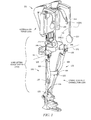
- FIG. 1 is a front view perspective drawing illustrating an example portable load lifting assist system 100 for aiding a human user comprising a lower extremity exoskeleton 120 and exoskeleton torso 160 including an exoskeleton trunk 109.
- Portable load lifting assist system 100 is wearable by a person and allows its wearer to carry a load in his/her front, and aid the person when lifting an object by significantly reducing the load on the user.
- portable load lifting assist system 100 can be used to help lift heavy loads while exerting minimal effort, such as in an example military application for soldiers going into combat with up to 130 pounds of combat gear.
- Lower extremity exoskeleton 120 in addition to other components, includes two leg supports, 101 and 102, which are configured to be coupled to person's lower limbs and configured to rest on the ground or other surface (e.g., a floor) during their stance phase.
- the leg supports 101 and 102 in addition to other components, include thigh links 103 and 104, and shank links 105 and 106.
- Two knee joints, 107 and 108 are configured to allow flexion and extension between the shank links 105 and 106 and the thigh links 103 and 104 of the leg supports 101, 102 during the corresponding leg support swing phase.
- the two knee joints 107 and 108 in some embodiments are configured to resist flexion between the shank links 105 and 106 and the thigh links 103 and 104 of the leg supports 101, 102 during the corresponding leg support stance phase.
- Exoskeleton torso 160 comprises an exoskeleton trunk 109.
- Exoskeleton trunk 109 comprises an upper body interface device 150.
- Exoskeleton trunk 109 is configurable to be coupled to the person's upper body through the upper body interface device 150.
- a person's upper body refers to any location generally above the thighs including the buttocks of the person.
- Examples of upper body interface devices 150 comprise an element or combination of elements including, without limitation, vests, belts, straps, shoulder straps, chest straps, body cast, harness, and waist belts.
- Exoskeleton trunk 109 is rotatably connectable to leg supports 101 and 102 at hip flexion-extension joints 125 and 126, allowing for the hip flexion and extension rotations of leg supports 101 and 102 about hip flexion-extension axes 151 and 152 respectively.
- Leg supports 101 and 102 are configurable to be coupled to person's lower limbs through lower limb interface straps, with the lower right interface strap 135 shown in FIG. 1 (left lower limb interface strap not shown in FIG. 1 for clarity).
- each lower limb interface strap is coupled to thigh links 103 and 104.
- lower limb interface straps are coupled to shank links 105 and 106.
- lower limb interface straps are coupled to both the shank links and thigh links.
- Each lower limb interface strap can comprise an element or combination of elements including, without limitation, straps, bars, c-shaped brackets, body cast, and elastomers.
- a person is coupled to (or wears) load lifting assist system 100 including exoskeleton torso 160 through upper body interface device 150 (a simple belt 150(a) and shoulder straps 150(b) shown in FIG. 1 ) and lower extremity exoskeleton 120 by coupling to two leg supports 101 and 102 through lower limb interface straps 135 and 136.
- lower extremity exoskeleton 120 may include two hip torque generators 145 and 146 which are configured to create torques between exoskeleton trunk 109 and leg supports 101 and 102.
- the exoskeleton torso 160 shown in FIG. 1 also includes a load lifting mechanism 221.
- the load lifting mechanism 221 in FIG. 1 has within it a winch 229 (see FIG. 3 ) which includes a reel mechanism which can reel in straps or lifting cables 222 that in one particular embodiment are nylon straps in order to lift a load connected to or contacted by end effectors 223.
- Disclosed portable load lifting systems include a power source (not shown) that can comprise a battery source, or other power sources such as fuel cell-based power sources.
- Disclosed portable load lifting assist systems such as portable load lifting assist system 100 shown in FIG. 1 are also easy for a user to put on.
- the portable load lifting assist system 100 can arrive folded in a small package, so that soldiers or other users simply stretch out a leg and step into foot beds underneath the boot. Straps can then wrap around the thighs, waist and shoulders of the soldier or other user.
- FIG. 2 shows an example exoskeleton torso 160 including the exoskeleton trunk 109 with a load lifting mechanism 221 connected to it, according to a disclosed embodiment.
- end effector 223 is shown as a simple paddle on which a high friction material is mounted on the side opposite handle 224.
- the high friction material is used to help grip the sides of boxes and box like objects.
- One particular example of an example high friction material is "GECKO SKIN.”
- end effector 223 may generally be any item used to lift a load and may contain a force sensor 251 in the handle 224 in order to measure the load force which the human user is putting on the handle.
- Item 225 is a lifting bar which (among other things) acts as a guide for cable 222.
- the load lifting mechanism 221 (including the internal winch, straps 222, end effectors 223, and handles 224) can be a mechanism sometimes referred to as a "human power amplifier.”
- a human power amplifier An example of such a "human power amplifier” is disclosed in U.S. Patent 6,886,812 to Kazerooni.
- the load lifting mechanism 221 can also include a movable counter weight 226 which may be rotated about counter weight rotation axis 227 (see FIG. 3 ) by a counterweight actuator 228 (see FIG. 4 ).
- a counterweight actuator 228 see FIG. 4 .
- One advantageous aspect of this feature is to make the mass of the counterweight 228 include the mass of the winch 229 (including its motor, indicated by the "M" in FIG. 3 ). This can be done by routing the lifting strap or cable 222 through the path shown in FIG. 3 .
- the strap or cable 222 passes over a pulley 236 which is concentric with the counter weight rotation axis 227 and therefore the motion of the counterweight 228 has very little affect on the length (or load) of the lifting strap or cable 222.
- the motor can comprise a hydraulic motor.
- Hydraulic motor-based architectures can be highly energy efficient to help support battery powered operation of disclosed systems including the portable load lifting assist system 100 shown in FIG. 1 .
- the counterweight 226 In operation of the load lifting mechanism 221, when loads in front of the user (on the end effectors 223) are high, the counterweight 226 is moved farther aft of the user in order to balance the load (at least partially) about the hip flexion-extension axes 151 and 152. This is shown occurring in FIG. 4 .
- a controller 411 such as comprising a microprocessor (or microcomputer) 412 coupled to a force sensor 413 shown in FIG. 4 which measures the force being applied by load lifting mechanism 221 to the lifting strap or cable 222.
- the controller 411 can then send a control signal that triggers movement of the movable counter weight 226 to a position appropriate to balance the moment created about hip flexion-extension axes 151 and 152 by the counter weight 226 with the moment created by the down force on the cables 222 due to the load in front of the user.
- a control signal that triggers movement of the movable counter weight 226 to a position appropriate to balance the moment created about hip flexion-extension axes 151 and 152 by the counter weight 226 with the moment created by the down force on the cables 222 due to the load in front of the user.
- hip torque generators 145 and 146 may be greatly reduced or even eliminated because the wearer of the exoskeleton torso 160 can provide the small amount of remaining torque needed to the keep the exoskeleton trunk 109 upright.
- a movable counter weight 226 which translated linearly or swung on a linkage type mechanism in a manner that would not be a rotation about a counter weight rotation axis 227. Any mechanism which will move the counterweight farther behind (or closer to) the hip flexion-extension axes 151 and 152 will generally be able to produce the desired effect.
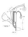
- FIG. 3 depicts a partial cross section depiction of an exemplary load lifting bar mechanism 230 associated with exoskeleton torso 160, according to a disclosed embodiment.
- the load lifting bar mechanism 230 includes a lifting bar 225, lifting bar guide 231, and cam plate 232.
- the lifting bar 225 slides over the lifting bar guide 231 in a telescopic fashion.
- the position of lifting bar 225 along the lifting bar guide 231 is determined by the cam roller 233 which is mounted on the lifting bar 225 and moves in a slot 234 on cam plate 232.
- the lifting bar guide 231 pivots on the pivot 235.
- Pulley 236 is a pulley over which the strap or cable 222 runs. When enough of the strap or cable 222 is retrieved such that the end effectors 223 are approaching the ends of the lifting bar 225, the lifting bar 225 starts to move upward and outward as the cam roller 233 moves upward in the slot 234 on cam plate 232.
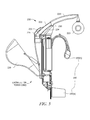
- FIG. 6 shows a close up view of the rear end of the lifting bar guide 231.
- the lifting strap 222 is actually comprised of two parts, the main lifting strap 237 and the lifting strap loop 238.
- the main strap 237 and the strap loop 238 are attached (e.g., sewn or bonded) together in the regions 239 and 240.
- the pulley 236 comprises a body 241 and flanges 242.
- the strap loop 238 encounters the pulley body 241 at a point where there is still strap available between the end of the lifting bar 225 and the end effector 223. If there were no strap available, the lifting bar 225 could not extend along the lifting bar guide 231 because it would be constrained by the strap or cable 222.
- load lifting bar mechanism 230 which solely by pulling on a strap or a cable, the lifting bars will move upward and outward when the strap or cable is near the end of its travel. This allows the wearer of exoskeleton torso 160 to lift loads up to much higher heights than retracted lifting bars would allow.
- the portable load lifting assist system is not attached to a lower extremity exoskeleton 120 as described above relative to FIGS. 1-6 .
- the portable load lifting assist system can comprise only exoskeleton torso 160 which can be worn by a user analogous to a backpack.
- FIG. 7 shows a depiction of an exemplary portable load lifting assist system 700 that includes straps 710 that allows the portable load lifting assist system 700 comprising exoskeleton trunk 109 to be worn by a user like a backpack.
- the movable counter weight 226 is identified in FIG. 7 by its function "counter-balance mechanism".
- the portable load lifting system can be attached to a mobile unit.
- FIG. 8 shows an exemplary portable load lifting system 800 that comprises a cart 820 including wheels 825 that mounts an example load lifting system 840 on a movable support structure 810 (e.g., bolted or welded) that is secured to the cart 820.
- the movable support structure 810 has mobility via the cart 820.
- Portable load lifting system 800 as well as disclosed portable load lifting assist systems can be used to support a variety of applications, including military, industrial and medical applications. assist soldiers during combat.
- disclosed portable load lifting systems include simplicity of actuation and flexibility to relocate to alternate work or other areas. Unlike a fully articulated arm, disclosed embodiments can use minimal sensing and actuation capability. This reduces the cost and power requirements and improves the reliability of the design as compared to an actuated arm. Also, unlike known fixed load attachment, load lifting systems disclosed herein allow for the raising and lowering of the load. For example, a user such as a soldier using a disclosed portable lifting assist system can raise a load above his or her shoulders, as well as lower the load to the ground.
- portable load lifting systems disclosed herein have significantly enhanced flexibility in its usage. Because disclosed load lifting systems are not physically restrained to a work area, a user can operate the load lifting system inside a warehouse one minute, then head directly outside and continue to operate the load lifting system. This provides much greater utility to the user at lower cost and with lower power consumption.
Landscapes
- Engineering & Computer Science (AREA)
- Mechanical Engineering (AREA)
- Robotics (AREA)
- Manipulator (AREA)
Description
- Disclosed embodiments relate to portable load lifting systems.
- Certain jobs require individuals to repetitively lift and carry heavy loads. These activities significantly increase muscular-skeletal stress on the body, potentially leading to injuries, with some injuries potentially being permanent injuries.
- One known load lifting assist system utilizes an exoskeleton which incorporates fully articulated arms to allow for upper body lift assist. These arms have a similar range of motion to the user's arms and require significant sensing and actuation to ensure the system tracks the user to avoid any discomfort. Additionally, loads can be carried by utilizing a fixed load attachment which supports the load on the user, but prohibits raising or lowering the load from the fixed attachment point.
- Another known lifting assist system has a fixed load assist mechanism that is built into the infrastructure of a warehouse or other facility. Typically the lift assist mechanism in this system is permanently attached to a fixed overhead gantry. This arrangement is thus limited to use within a limited region of the warehouse or other facility.
-
US Patent No. 3,964,182 discloses a mechanical shovel which comprises a digging tool, two booms and a harness. One of the booms is adapted to be mounted by the harness on and substantially parallel to the back of an operator so that the other boom extends forwardly of the operator. One of the booms supports a winding mechanism having a cable leading along the forwardly extending boom and attached to the handle of the digging tool. The handle of the digging tool is provided with means to activate the winding mechanism so that the shovel may be raised with the minimum of effort on the part of the operator. The combination of the two booms provides a particularly stable arrangement. - Disclosed embodiments include portable load lifting systems that provide powered assisted straps or cables coupled to end-effectors for lifting and carrying or moving heavy loads. In one embodiment, the portable load lifting system is a load lifting assist system that can be worn by a human user to transfer the weight of the load through the frame of the load lifting assist system to the ground or other lower surface (e.g., a floor). In this embodiment, loads attached to the load lifting assist system are carried by the exoskeleton, significantly reducing the load on the user, thus reducing the risk of muscular skeletal injuries and allowing more weight to be carried by the user.
- Other embodiments disclosed herein include portable load lifting assist systems that are independent of a lower extremity exoskeleton. For example, the portable load lifting assist system can be worn like a backpack (e.g., secured by straps to a torso of a user). In another embodiment the portable load lifting system is operable without the need to be secured to a human user, such including a mobile unit (e.g., a cart on wheels) that provides the system its support and portability.
- Additionally, disclosed embodiments include portable load lifting assist systems that include structures that allow users to raise loads up to a minimum of shoulder height while still providing lift assistance. The power-assisted straps or cables enable a user to safely accomplish tasks that would typically require two or more personnel to carry the load. The end-effectors are quickly and easily exchanged to enable lift and carriage of many different items such as boxes, containers or munitions. Disclosed portable load lifting assist system embodiments allow for the normal lifting range of motion of a person, and through the use of disclosed shoulder lifting devices, allows the user to raise loads to shoulder height and above while still providing significant lift assistance.
- Cantilevered weight can be used to keep the center of gravity close to the user to maintain balance and positive control of the load. Force sensors within the end-effectors can feed an onboard microprocessor-based controller to ensure system movement in concert with the user enabling accurate placement of objects that are lifted by the user. By detecting the force input by the user such as by including force sensors on the end effectors allows disclosed portable load lifting assist systems to also able to detect the user's intent (raise, lower or stabilize) and to provide the appropriate assistance to implement the user's intent via the lifting straps or cables attached to the end-effectors.
-
-
FIG. 1 is a front view perspective drawing of an example portable load lifting assist system for aiding a human user comprising a lower extremity exoskeleton and exoskeleton torso, according to a disclosed embodiment. -
FIG. 2 shows an example exoskeleton torso including the exoskeleton trunk with a load lifting mechanism connected to it, according to a disclosed embodiment. -
FIG. 3 depicts a partial cross section depiction of an example load lifting bar mechanism, according to a disclosed embodiment. -
FIG. 4 depicts the counterweight moved farther aft of the user in order to balance the load (at least partially) about the hip flexion-extension axes, which is useful in situations when loads in front of the user (on the end effectors) are high, according to a disclosed embodiment. -
FIG. 5 depicts the position of lifting bar along the lifting bar guide being determined by the cam roller which is mounted on the lifting bar and moves in a slot on cam plate, wherein the lifting bar guide pivots on the pivot, and the pulley is a pulley over which the strap runs, according to a disclosed embodiment. -
FIG. 6 is a close up view of the rear end of an example lifting bar guide, according to a disclosed embodiment. -
FIG. 7 shows a depiction of an example portable load lifting assist system that includes lifting straps that allow the portable load lifting assist system to be worn like a backpack, according to another disclosed embodiment. -
FIG. 8 shows an example portable load lifting system that comprises a cart including wheels that mounts the load lifting mechanism on a support structure that is secured to the cart, according to another disclosed embodiment. - Disclosed embodiments are described with reference to the attached figures, wherein like reference numerals, are used throughout the figures to designate similar or equivalent elements. The figures are not drawn to scale and they are provided merely to illustrate aspects disclosed herein. Several disclosed aspects are described below with reference to example applications for illustration. It should be understood that numerous specific details, relationships, and methods are set forth to provide a full understanding of the embodiments disclosed herein. One having ordinary skill in the relevant art, however, will readily recognize that the disclosed embodiments can be practiced without one or more of the specific details or with other methods. In other instances, well-known structures or operations are not shown in detail to avoid obscuring aspects disclosed herein. Disclosed embodiments are not limited by the illustrated ordering of acts or events, as some acts may occur in different orders and/or concurrently with other acts or events. Furthermore, not all illustrated acts or events are required to implement a methodology in accordance with this Disclosure.
- Disclosed portable load lifting systems comprise a movable support structure and a load lifting mechanism secured to the movable support structure comprising a winch including a motor driven reel mechanism for reeling first and second lifting straps or cables that are secured to first and second end effectors. First and second handles are attached to an outside surface of the first and second end effectors, where the lifting straps or cables when driven by the winch lift a load contacted by the first and second end effectors. The portable load lifting system can comprise a load lifting assist system for aiding a human user that includes a lower extremity exoskeleton and an exoskeleton torso, or can be embodied in other disclosed embodiments to include an exoskeleton torso but not a lower extremity exoskeleton. Other disclosed embodiments comprise load lifting systems that are operable without the need to be secured to a human user.
- In accordance with an example embodiment,
FIG. 1 is a front view perspective drawing illustrating an example portable loadlifting assist system 100 for aiding a human user comprising alower extremity exoskeleton 120 andexoskeleton torso 160 including anexoskeleton trunk 109. Portable loadlifting assist system 100 is wearable by a person and allows its wearer to carry a load in his/her front, and aid the person when lifting an object by significantly reducing the load on the user. For example, portable loadlifting assist system 100 can be used to help lift heavy loads while exerting minimal effort, such as in an example military application for soldiers going into combat with up to 130 pounds of combat gear. -
Lower extremity exoskeleton 120, in addition to other components, includes two leg supports, 101 and 102, which are configured to be coupled to person's lower limbs and configured to rest on the ground or other surface (e.g., a floor) during their stance phase. The leg supports 101 and 102, in addition to other components, includethigh links shank links shank links thigh links knee joints shank links thigh links -
Exoskeleton torso 160, among other components, comprises anexoskeleton trunk 109.Exoskeleton trunk 109, among other components, comprises an upperbody interface device 150.Exoskeleton trunk 109 is configurable to be coupled to the person's upper body through the upperbody interface device 150. As used herein, a person's upper body refers to any location generally above the thighs including the buttocks of the person. Examples of upperbody interface devices 150 comprise an element or combination of elements including, without limitation, vests, belts, straps, shoulder straps, chest straps, body cast, harness, and waist belts. -
Exoskeleton trunk 109 is rotatably connectable to leg supports 101 and 102 at hip flexion-extension joints extension axes right interface strap 135 shown inFIG. 1 (left lower limb interface strap not shown inFIG. 1 for clarity). - In some embodiments such as shown in
FIG. 1 , the respective lower limb interface straps are coupled tothigh links shank links - In operation, a person is coupled to (or wears) load
lifting assist system 100 includingexoskeleton torso 160 through upper body interface device 150 (a simple belt 150(a) and shoulder straps 150(b) shown inFIG. 1 ) andlower extremity exoskeleton 120 by coupling to two leg supports 101 and 102 through lower limb interface straps 135 and 136. In some embodiments,lower extremity exoskeleton 120 among other things, may include twohip torque generators exoskeleton trunk 109 and leg supports 101 and 102. - The
exoskeleton torso 160 shown inFIG. 1 also includes aload lifting mechanism 221. Theload lifting mechanism 221 inFIG. 1 has within it a winch 229 (seeFIG. 3 ) which includes a reel mechanism which can reel in straps or liftingcables 222 that in one particular embodiment are nylon straps in order to lift a load connected to or contacted byend effectors 223. - Disclosed portable load lifting systems include a power source (not shown) that can comprise a battery source, or other power sources such as fuel cell-based power sources. Disclosed portable load lifting assist systems such as portable load lifting
assist system 100 shown inFIG. 1 are also easy for a user to put on. The portable load liftingassist system 100 can arrive folded in a small package, so that soldiers or other users simply stretch out a leg and step into foot beds underneath the boot. Straps can then wrap around the thighs, waist and shoulders of the soldier or other user. -
FIG. 2 shows anexample exoskeleton torso 160 including theexoskeleton trunk 109 with aload lifting mechanism 221 connected to it, according to a disclosed embodiment. InFIG. 2 ,end effector 223 is shown as a simple paddle on which a high friction material is mounted on the side oppositehandle 224. The high friction material is used to help grip the sides of boxes and box like objects. One particular example of an example high friction material is "GECKO SKIN." However,end effector 223 may generally be any item used to lift a load and may contain aforce sensor 251 in thehandle 224 in order to measure the load force which the human user is putting on the handle.Item 225 is a lifting bar which (among other things) acts as a guide forcable 222. In one embodiment the load lifting mechanism 221 (including the internal winch, straps 222,end effectors 223, and handles 224) can be a mechanism sometimes referred to as a "human power amplifier." An example of such a "human power amplifier" is disclosed inU.S. Patent 6,886,812 to Kazerooni. - The
load lifting mechanism 221 can also include amovable counter weight 226 which may be rotated about counter weight rotation axis 227 (seeFIG. 3 ) by a counterweight actuator 228 (seeFIG. 4 ). One advantageous aspect of this feature is to make the mass of thecounterweight 228 include the mass of the winch 229 (including its motor, indicated by the "M" inFIG. 3 ). This can be done by routing the lifting strap orcable 222 through the path shown inFIG. 3 . The strap orcable 222 passes over apulley 236 which is concentric with the counterweight rotation axis 227 and therefore the motion of thecounterweight 228 has very little affect on the length (or load) of the lifting strap orcable 222. - In one embodiment the motor can comprise a hydraulic motor. Hydraulic motor-based architectures can be highly energy efficient to help support battery powered operation of disclosed systems including the portable load lifting
assist system 100 shown inFIG. 1 . - In operation of the
load lifting mechanism 221, when loads in front of the user (on the end effectors 223) are high, thecounterweight 226 is moved farther aft of the user in order to balance the load (at least partially) about the hip flexion-extension axes FIG. 4 . This may be accomplished by using acontroller 411 such as comprising a microprocessor (or microcomputer) 412 coupled to aforce sensor 413 shown inFIG. 4 which measures the force being applied byload lifting mechanism 221 to the lifting strap orcable 222. - The
controller 411 can then send a control signal that triggers movement of themovable counter weight 226 to a position appropriate to balance the moment created about hip flexion-extension axes counter weight 226 with the moment created by the down force on thecables 222 due to the load in front of the user. One having ordinary skill in the art will note that there are many ways to measure the force incables 222 and approximate the moment created by that force about hip flexion-extension axes exoskeleton trunk 109 about hip flexion-extension axes hip torque generators exoskeleton torso 160 can provide the small amount of remaining torque needed to the keep theexoskeleton trunk 109 upright. - One having ordinary skill in the art can construct a
movable counter weight 226 which translated linearly or swung on a linkage type mechanism in a manner that would not be a rotation about a counterweight rotation axis 227. Any mechanism which will move the counterweight farther behind (or closer to) the hip flexion-extension axes -
FIG. 3 depicts a partial cross section depiction of an exemplary load liftingbar mechanism 230 associated withexoskeleton torso 160, according to a disclosed embodiment. The loadlifting bar mechanism 230 includes a liftingbar 225, liftingbar guide 231, andcam plate 232. The liftingbar 225 slides over the liftingbar guide 231 in a telescopic fashion. - Referring to
FIG. 5 , the position of liftingbar 225 along the liftingbar guide 231 is determined by thecam roller 233 which is mounted on the liftingbar 225 and moves in aslot 234 oncam plate 232. The liftingbar guide 231 pivots on thepivot 235.Pulley 236 is a pulley over which the strap orcable 222 runs. When enough of the strap orcable 222 is retrieved such that theend effectors 223 are approaching the ends of the liftingbar 225, the liftingbar 225 starts to move upward and outward as thecam roller 233 moves upward in theslot 234 oncam plate 232. - To understand how the strap or
cable 222 causes the liftingbar 225 to move upward and outward,FIG. 6 shows a close up view of the rear end of the liftingbar guide 231. InFIG. 6 , it can be seen that the liftingstrap 222 is actually comprised of two parts, themain lifting strap 237 and the liftingstrap loop 238. Themain strap 237 and thestrap loop 238 are attached (e.g., sewn or bonded) together in theregions pulley 236 comprises abody 241 andflanges 242. When the strap orcable 222 is pulled towards thewinch 229, eventually the liftingstrap loop 238 will wrap around thepulley body 241 and begin pulling downward on the pulley body. This will cause the liftingbar guide 231 to pivot on thepivot 235 which will cause the liftingbar 225 to move upward and outward. Thestrap loop 238 encounters thepulley body 241 at a point where there is still strap available between the end of the liftingbar 225 and theend effector 223. If there were no strap available, the liftingbar 225 could not extend along the liftingbar guide 231 because it would be constrained by the strap orcable 222. - One having ordinary skill in the art will note that there are many ways to construct a load lifting
bar mechanism 230 which solely by pulling on a strap or a cable, the lifting bars will move upward and outward when the strap or cable is near the end of its travel. This allows the wearer ofexoskeleton torso 160 to lift loads up to much higher heights than retracted lifting bars would allow. - In other disclosed embodiments, the portable load lifting assist system is not attached to a
lower extremity exoskeleton 120 as described above relative toFIGS. 1-6 . For example, the portable load lifting assist system can compriseonly exoskeleton torso 160 which can be worn by a user analogous to a backpack. -
FIG. 7 shows a depiction of an exemplary portable load liftingassist system 700 that includesstraps 710 that allows the portable load liftingassist system 700 comprisingexoskeleton trunk 109 to be worn by a user like a backpack. Themovable counter weight 226 is identified inFIG. 7 by its function "counter-balance mechanism". - In yet another embodiment, the portable load lifting system can be attached to a mobile unit.
FIG. 8 shows an exemplary portableload lifting system 800 that comprises acart 820 includingwheels 825 that mounts an exampleload lifting system 840 on a movable support structure 810 (e.g., bolted or welded) that is secured to thecart 820. Themovable support structure 810 has mobility via thecart 820. Portableload lifting system 800 as well as disclosed portable load lifting assist systems can be used to support a variety of applications, including military, industrial and medical applications. assist soldiers during combat. - Advantages of disclosed portable load lifting systems include simplicity of actuation and flexibility to relocate to alternate work or other areas. Unlike a fully articulated arm, disclosed embodiments can use minimal sensing and actuation capability. This reduces the cost and power requirements and improves the reliability of the design as compared to an actuated arm. Also, unlike known fixed load attachment, load lifting systems disclosed herein allow for the raising and lowering of the load. For example, a user such as a soldier using a disclosed portable lifting assist system can raise a load above his or her shoulders, as well as lower the load to the ground.
- Moreover, unlike known overhead lift devices integrated and thus fixed into the building infrastructure, portable load lifting systems disclosed herein have significantly enhanced flexibility in its usage. Because disclosed load lifting systems are not physically restrained to a work area, a user can operate the load lifting system inside a warehouse one minute, then head directly outside and continue to operate the load lifting system. This provides much greater utility to the user at lower cost and with lower power consumption.
- While various disclosed embodiments have been described above, it should be understood that they have been presented by way of example only, and not as a limitation. Numerous changes to the disclosed embodiments can be made in accordance with the Disclosure herein. Thus, the breadth of this Disclosure should not be limited by any of the above-described embodiments. Rather, the scope of this Disclosure should be defined in accordance with the following claims and their equivalents.
- Although disclosed embodiments have been illustrated and described with respect to one or more implementations, equivalent alterations and modifications will occur to others skilled in the art upon the reading and understanding of this specification and the annexed drawings. While a particular feature may have been disclosed with respect to only one of several implementations, such a feature may be combined with one or more other features of the other implementations as may be desired and advantageous for any given or particular application.
Claims (15)
- A portable load lifting system (100), comprising:a movable support structure;a load lifting mechanism (221) secured to said movable support structure comprising a winch (229) including a motor driven reel mechanism for reeling first and second lifting straps or cables that are secured to first and second end effectors (223); wherein a gripping element is provided on the inside surface of the first and second end effectors (223) for gripping the load, andfirst and second handles (224) attached to an outside surface of said first and second end effectors (223), wherein said straps or cables when driven by said winch (229) lift a load contacted by said first and second end effectors (223).
- The system of claim 1, wherein said movable support structure comprises an exoskeleton torso (160) including an exoskeleton trunk (109) that is configured to be coupled to a person's upper body through an upper body interface device (150).
- The system of claim 2, wherein said upper body interface device (150) comprises a vest, a belt, shoulder straps, chest straps, a body cast, harness, or a waist belt.
- The system of claim 1, further comprising a first and a second force sensor in said first and second handles, wherein said first and second force sensors (251) measure a load force which a person is putting on said first and second handles (224).
- The system of claim 1, further comprising a lifting bar (225) for guiding said lifting straps or cables.
- The system of claim 1, further comprising a movable counter weight (226) which is rotatable about a counter weight rotation axis by a counterweight actuator so that a mass of said counterweight (226) includes a mass of said winch (229).
- The system of claim 6, further comprising a controller (411) including a microprocessor or microcomputer (412) and a force sensor (251) which measures a force being applied by said load lifting mechanism (221) to said lifting straps or cables,
wherein said controller (411) is operable to send a control signal that controls a position of said movable counter weight (226) to a position appropriate to balance a moment created about hip flexion-extension axes by the counter weight (226) with a moment created by the down force on said lifting straps or cables in front of a person. - The system of claim 1, further comprising a load lifting bar mechanism (230) comprising a first and a second lifting bar (225), which exclusively by pulling said lifting straps or cable, said first and said second lifting bar will move upward and outward when said lifting straps or cable is near an end of its travel.
- The system of claim 8, further comprising a lifting bar guide (231), and cam plate (232), wherein said lifting bar (225) slides over said lifting bar guide (231) in a telescopic fashion, and a position of said lifting bar (225) along the lifting bar guide (231) is determined by a cam roller (233) which is mounted on said lifting bar (225) and moves in a slot on said cam plate (232), said lifting bar guide (231) pivoting on a pivot, and
a pulley (236) over which said lifting straps or cables (222) runs,
wherein when enough of said lifting straps or cables (222) is retrieved such that said first and second effectors (223) are approaching ends of said lifting bar (225), said lifting bar (225) starts to move upward and outward as said cam roller (233) moves upward in said slot on said cam plate (232). - The system of claim 1, wherein said movable support structure is mounted on a mobile unit (810).
- The system of claim 10, wherein said mobile unit includes wheels.
- The system of claim 1, further comprising a lower extremity exoskeleton (120) configured to be coupled to a person's lower limbs, wherein said movable support structure comprises an exoskeleton torso (160) including an exoskeleton trunk (109) that is configured to be coupled to an upper body of said person through an upper body interface device (150) that is coupled to said lower extremity exoskeleton.
- The system of claim 12, wherein said lower extremity exoskeleton (120) comprises leg supports (101, 102), and said exoskeleton trunk (109) is rotatably connectable to said leg supports (101, 102) at hip flexion-extension joints for hip flexion and extension rotations of leg supports about hip flexion-extension axes.
- The system of claim 1, wherein said motor comprise a hydraulic motor.
- The system according to any of claims 4, 6 to 9 or 13:wherein said movable support structure comprises an exoskeleton torso (160) including an exoskeleton trunk (109) that is configured to be coupled to a person's upper body;and further comprising:a lower extremity exoskeleton (120) configured to be coupled to a person's lower limbs,wherein said exoskeleton trunk (109) couples to an upper body of said person through an upper body interface device (150) that is coupled to said lower extremity exoskeleton.
Applications Claiming Priority (2)
| Application Number | Priority Date | Filing Date | Title |
|---|---|---|---|
| US32268410P | 2010-04-09 | 2010-04-09 | |
| PCT/US2011/031956 WO2011127471A1 (en) | 2010-04-09 | 2011-04-11 | Portable load lifting system |
Publications (3)
| Publication Number | Publication Date |
|---|---|
| EP2556010A1 EP2556010A1 (en) | 2013-02-13 |
| EP2556010A4 EP2556010A4 (en) | 2014-06-25 |
| EP2556010B1 true EP2556010B1 (en) | 2015-11-25 |
Family
ID=44763313
Family Applications (1)
| Application Number | Title | Priority Date | Filing Date |
|---|---|---|---|
| EP11766862.4A Active EP2556010B1 (en) | 2010-04-09 | 2011-04-11 | Portable load lifting system |
Country Status (5)
| Country | Link |
|---|---|
| US (1) | US9333644B2 (en) |
| EP (1) | EP2556010B1 (en) |
| JP (1) | JP6008836B2 (en) |
| CN (1) | CN103038152A (en) |
| WO (1) | WO2011127471A1 (en) |
Families Citing this family (101)
| Publication number | Priority date | Publication date | Assignee | Title |
|---|---|---|---|---|
| US9656117B2 (en) | 2009-06-19 | 2017-05-23 | Tau Orthopedics, Llc | Wearable resistance garment with power measurement |
| US10124205B2 (en) | 2016-03-14 | 2018-11-13 | Tau Orthopedics, Llc | Toning garment with modular resistance unit docking platforms |
| WO2011036906A1 (en) * | 2009-09-28 | 2011-03-31 | 学校法人東京理科大学 | Lumbar support device |
| FR2978690A1 (en) * | 2011-08-02 | 2013-02-08 | Pierre Andre Davezac | Electronic exoskeleton for lifting and carrying loads in e.g. military, has hook descended on ground in which load rests and secured to worker when worker is entitled by preserving arms to stabilize before load is suspended to height |
| JP6169837B2 (en) * | 2011-11-02 | 2017-07-26 | パナソニック株式会社 | Lower limb movement support device |
| US20130145530A1 (en) * | 2011-12-09 | 2013-06-13 | Manu Mitra | Iron man suit |
| WO2013106532A1 (en) | 2012-01-11 | 2013-07-18 | Brown Garrett W | Load and torque resistant caliper exoskeleton |
| CN102805915A (en) * | 2012-08-06 | 2012-12-05 | 陈建瑜 | Intelligent power assisting system |
| CN104869970B (en) * | 2012-12-11 | 2017-09-29 | 埃克苏仿生公司 | Reconfigurable ectoskeleton |
| CN103006416B (en) * | 2013-01-04 | 2014-08-20 | 哈尔滨工程大学 | Mechanical lower-limb rehabilitation robot walker device |
| EP2968053B1 (en) * | 2013-03-14 | 2022-07-27 | Ekso Bionics, Inc. | Non-anthropomorphic hip joint locations for exoskeletons |
| CN103284819B (en) * | 2013-04-24 | 2015-08-19 | 西南交通大学 | A kind of assistance type ectoskeleton is with front lifting formula adjustable back negative system |
| JP6284318B2 (en) * | 2013-08-30 | 2018-02-28 | 三菱重工業株式会社 | Power assist suit |
| JP6284319B2 (en) * | 2013-08-30 | 2018-02-28 | 三菱重工業株式会社 | Power assist suit |
| KR101500525B1 (en) * | 2013-10-16 | 2015-03-09 | 대우조선해양 주식회사 | folding working unit for wearable robot |
| ITFR20130013A1 (en) * | 2013-11-25 | 2015-05-26 | Marco Ceccarelli | EXOSCHELETER DEVICE FOR ASSISTANCE TO HUMAN LOCOMOTION. |
| JP5902664B2 (en) * | 2013-12-25 | 2016-04-13 | ファナック株式会社 | Human cooperative industrial robot with protective member |
| FR3016821B1 (en) * | 2014-01-29 | 2019-08-02 | Robotiques 3 Dimensions | EXOSQUELETTE WITH FRONT PORT AND METHOD OF USING SUCH AN EXOSQUELET. |
| JP6184355B2 (en) * | 2014-03-20 | 2017-08-23 | 株式会社クボタ | Assist suit |
| JP6153881B2 (en) * | 2014-03-20 | 2017-06-28 | 株式会社クボタ | Assist suit |
| JP6148192B2 (en) * | 2014-03-20 | 2017-06-14 | 株式会社クボタ | Assist suit |
| EP3119369A4 (en) * | 2014-03-21 | 2017-11-29 | Ekso Bionics, Inc. | Ambulatory exoskeleton and method of relocating exoskeleton |
| US9604369B2 (en) * | 2014-06-04 | 2017-03-28 | Ekso Bionics, Inc. | Exoskeleton and method of increasing the flexibility of an exoskeleton hip joint |
| RU2696631C2 (en) * | 2014-06-18 | 2019-08-05 | Маваши Протектив Клоузинг Инк. | Exoskeleton and method of its use |
| US9808073B1 (en) * | 2014-06-19 | 2017-11-07 | Lockheed Martin Corporation | Exoskeleton system providing for a load transfer when a user is standing and kneeling |
| CN104013514B (en) * | 2014-06-19 | 2017-02-15 | 中国北方车辆研究所 | Hydraulically-driven wearable human body assisting walking robot |
| KR102250235B1 (en) * | 2014-07-17 | 2021-05-10 | 삼성전자주식회사 | A fixing module and a motion assist apparatus comprising thereof |
| US20160158593A1 (en) * | 2014-12-04 | 2016-06-09 | Florida Institute for Human and Machine Cognition | Exoskeleton-Based Exercise and Training Device |
| JP6504823B2 (en) * | 2015-01-14 | 2019-04-24 | 株式会社クボタ | Assist suit |
| KR102196104B1 (en) | 2015-01-14 | 2020-12-30 | 가부시끼 가이샤 구보다 | Assistive suit |
| JP2016130160A (en) * | 2015-01-14 | 2016-07-21 | 株式会社クボタ | Assist suit |
| JP6548394B2 (en) * | 2015-01-14 | 2019-07-24 | 株式会社クボタ | Assist suit |
| JP2016129917A (en) * | 2015-01-14 | 2016-07-21 | 株式会社クボタ | Assist suit |
| CN104669249B (en) * | 2015-02-01 | 2016-05-04 | 襄阳新火炬科技有限公司 | One hydraulic drive type robot |
| EP3064822B1 (en) * | 2015-03-02 | 2018-05-30 | Easyrig AB | Camera rig |
| US10390973B2 (en) | 2015-05-11 | 2019-08-27 | The Hong Kong Polytechnic University | Interactive exoskeleton robotic knee system |
| JP6673940B2 (en) * | 2015-05-18 | 2020-04-01 | ザ リージェンツ オブ ザ ユニバーシティ オブ カリフォルニア | Arm support exoskeleton |
| US10548800B1 (en) | 2015-06-18 | 2020-02-04 | Lockheed Martin Corporation | Exoskeleton pelvic link having hip joint and inguinal joint |
| US10195736B2 (en) | 2015-07-17 | 2019-02-05 | Lockheed Martin Corporation | Variable force exoskeleton hip joint |
| US10518404B2 (en) | 2015-07-17 | 2019-12-31 | Lockheed Martin Corporation | Variable force exoskeleton hip joint |
| CN105105896B (en) * | 2015-09-17 | 2016-11-30 | 武汉大学 | For the adjusting means that wearable lower limb exoskeleton robot is fixing with human body waist |
| GB2557554B (en) | 2015-10-30 | 2021-03-24 | Ekso Bionics Inc | Human exoskeleton devices for heavy tool support and use |
| JP6643874B2 (en) * | 2015-11-20 | 2020-02-12 | 株式会社クボタ | Assist suit |
| JP6754563B2 (en) * | 2015-11-20 | 2020-09-16 | 株式会社クボタ | Assist suit |
| KR102062998B1 (en) | 2015-11-20 | 2020-01-06 | 가부시끼 가이샤 구보다 | Assist suit |
| JP6541553B2 (en) * | 2015-11-20 | 2019-07-10 | 株式会社クボタ | Assist suit |
| JP6541552B2 (en) * | 2015-11-20 | 2019-07-10 | 株式会社クボタ | Assist suit |
| US10912346B1 (en) | 2015-11-24 | 2021-02-09 | Lockheed Martin Corporation | Exoskeleton boot and lower link |
| US10124484B1 (en) | 2015-12-08 | 2018-11-13 | Lockheed Martin Corporation | Load-bearing powered exoskeleton using electromyographic control |
| FR3046051B1 (en) * | 2015-12-24 | 2020-11-13 | Sagem Defense Securite | BACK MODULE FOR AN EXOSKELETON STRUCTURE |
| JP6533874B2 (en) | 2015-12-24 | 2019-06-19 | サフラン・エレクトロニクス・アンド・デファンス | Modular exoskeleton structure to provide users with force support |
| FR3046038B1 (en) * | 2015-12-24 | 2017-12-22 | Sagem Defense Securite | BACKPACK SUPPORT MODULE FOR A MODULAR STRUCTURE OF EXOSQUELET |
| JP6671179B2 (en) * | 2016-01-15 | 2020-03-25 | 株式会社クボタ | Assist equipment |
| CN108430714B (en) | 2016-01-15 | 2021-06-08 | 株式会社久保田 | Auxiliary implement |
| JP6671180B2 (en) * | 2016-01-15 | 2020-03-25 | 株式会社クボタ | Assist equipment |
| CN105853145B (en) * | 2016-04-12 | 2020-10-09 | 合肥工业大学 | Leg mechanical mechanism capable of realizing walking function |
| US11209121B2 (en) * | 2016-04-26 | 2021-12-28 | The Boeing Company | Lifting support device and method of controlling operation |
| JP6566912B2 (en) * | 2016-06-28 | 2019-08-28 | 株式会社クボタ | Assist suit |
| JP2018002333A (en) * | 2016-06-28 | 2018-01-11 | 株式会社クボタ | Assist suit |
| CN106346452B (en) * | 2016-11-02 | 2017-06-23 | 广州初曲科技有限公司 | A kind of air-electricity linkage formula ectoskeleton chain drive that the small of the back strength auxiliary is provided |
| CN109937123A (en) * | 2016-12-22 | 2019-06-25 | 株式会社久保田 | Ancillary equipment |
| FR3061445B1 (en) * | 2016-12-29 | 2019-05-24 | Safran Electronics & Defense | BONDING DEVICE FOR EXOSKELET STRUCTURE FACILITATING THE LOADING OF LOADS DURING THE MARKET OR THE RACE |
| CN106821689B (en) * | 2017-01-19 | 2023-07-04 | 武汉云云天下信息科技有限公司 | Wearable human exoskeleton robot |
| CN106628806A (en) * | 2017-02-28 | 2017-05-10 | 深圳龙海特机器人科技有限公司 | Double-open wearing-type auxiliary carrying device |
| JP2018149624A (en) * | 2017-03-13 | 2018-09-27 | パナソニック株式会社 | Motion assist device |
| JP6783171B2 (en) * | 2017-03-23 | 2020-11-11 | 株式会社クボタ | Assist equipment |
| JP6742274B2 (en) * | 2017-05-18 | 2020-08-19 | 株式会社クボタ | Assist suit |
| JP2017149585A (en) * | 2017-05-30 | 2017-08-31 | 株式会社クボタ | Assist suit |
| EP3647255B1 (en) * | 2017-06-29 | 2023-12-20 | Kubota Corporation | Assist device with hand portions for holding baggage |
| WO2019046408A1 (en) | 2017-08-30 | 2019-03-07 | Lockheed Martin Corporation | Automatic sensor selection |
| CN110253540B (en) * | 2017-09-07 | 2022-05-17 | 重庆市牛迪科技发展有限公司 | Exoskeleton |
| WO2019067835A1 (en) * | 2017-09-28 | 2019-04-04 | Ossur Iceland Ehf | Body interface |
| CN107569367B (en) * | 2017-10-18 | 2021-09-17 | 房倩玉 | Lower limb rehabilitation training device |
| US10835443B2 (en) * | 2017-11-13 | 2020-11-17 | Free Bionics Taiwan Inc. | Exoskeleton robot |
| DE102018103300A1 (en) * | 2018-02-14 | 2019-08-14 | Noonee Ag | Portable sitting position help device |
| CN109081038A (en) * | 2018-09-18 | 2018-12-25 | 上海工程技术大学 | A kind of wearable work-saving device |
| USD947388S1 (en) * | 2018-12-10 | 2022-03-29 | Jtekt Corporation | Motion assisting device |
| JP6758364B2 (en) * | 2018-12-25 | 2020-09-23 | 株式会社クボタ | Assist suit |
| US10765911B1 (en) | 2019-03-01 | 2020-09-08 | Dustin Hamoy | Core exercise assembly |
| JP6749443B2 (en) * | 2019-03-07 | 2020-09-02 | 株式会社クボタ | Assist suit |
| JP6756002B2 (en) * | 2019-05-07 | 2020-09-16 | 株式会社クボタ | Assist suit |
| JP7240264B2 (en) | 2019-06-12 | 2023-03-15 | Kyb株式会社 | electric power steering device |
| JP7427321B2 (en) * | 2019-06-18 | 2024-02-05 | 株式会社キトー | Power control device and power control method |
| CN110575366B (en) * | 2019-09-19 | 2022-01-18 | 哈尔滨工业大学 | Active and passive combined lower limb assistance exoskeleton robot |
| KR102422726B1 (en) * | 2019-11-27 | 2022-07-20 | 피씨오낙(주) | transporter for goods and carrier for child |
| CN111285280B (en) * | 2020-02-02 | 2021-08-31 | 广西电网有限责任公司北海供电局 | Backpack electric power high altitude construction transmission device |
| RU198903U1 (en) * | 2020-02-26 | 2020-07-31 | ООО "Экзомед" | Exoskeleton |
| JP2021186885A (en) * | 2020-05-25 | 2021-12-13 | 株式会社ジェイテクト | Assist device |
| RU202647U1 (en) * | 2020-06-11 | 2021-03-01 | Общество с ограниченной ответственностью "Экзомед" | Device for facilitating the movement of goods |
| EP4015156A1 (en) * | 2020-12-15 | 2022-06-22 | Auxivo AG | Load supporting device and its use |
| CN112936232B (en) * | 2021-04-08 | 2022-10-28 | 中国科学技术大学 | Hip joint exoskeleton robot system assisting diving |
| EP4079460A1 (en) * | 2021-04-22 | 2022-10-26 | Hilti Aktiengesellschaft | System, kit and electronic module for balancing a weight of an object |
| FR3125453A1 (en) * | 2021-07-26 | 2023-01-27 | Hublex | Assistance device for manual carrying of loads |
| CN113894771A (en) * | 2021-08-27 | 2022-01-07 | 北京机械设备研究所 | Active pull-belt type upper limb assistance exoskeleton |
| WO2023086541A1 (en) * | 2021-11-12 | 2023-05-19 | Hamon Richard A | Ladder hoist and cart system |
| DE102022100203A1 (en) * | 2022-01-05 | 2023-07-06 | J.Schmalz Gmbh | Auxiliary device that can be pulled on with an articulated connection to the lower body connection |
| DE102022100204A1 (en) * | 2022-01-05 | 2023-07-06 | J.Schmalz Gmbh | Auxiliary device that can be pulled on with an articulated connection to the upper body connection |
| CN114643571B (en) * | 2022-03-14 | 2023-07-21 | 南京赤研科技有限公司 | Full-freedom-degree upper limb exoskeleton device |
| CN114932536B (en) * | 2022-05-31 | 2023-07-28 | 山东大学 | Walking active mechanical device |
| CN114833804A (en) * | 2022-06-13 | 2022-08-02 | 山东瑞曼智能装备有限公司 | Active power assisting device and method suitable for multiple scenes |
| WO2024039310A1 (en) * | 2022-08-16 | 2024-02-22 | Interact Medikal Teknolojileri Anonim Sirketi | Adjustable passive exoskeleton |
Family Cites Families (51)
| Publication number | Priority date | Publication date | Assignee | Title |
|---|---|---|---|---|
| US2010482A (en) * | 1934-05-26 | 1935-08-06 | Florence M Henn | Walking motion |
| FR2249997B1 (en) * | 1973-10-31 | 1979-03-09 | Pomeret Jean Claude | |
| AT351794B (en) | 1977-11-10 | 1979-08-10 | Philips Nv | COIL SPRING CLUTCH |
| US5016869A (en) * | 1989-07-05 | 1991-05-21 | Applied Motion | Human bipedal locomotion device |
| JPH03105191U (en) | 1990-02-15 | 1991-10-31 | ||
| US5020790A (en) * | 1990-10-23 | 1991-06-04 | Board Of Supervisors Of Louisiana State University And Agricultural And Mechanical College | Powered gait orthosis |
| JP3024978U (en) | 1995-10-13 | 1996-06-07 | 吉村 敏正 | Backpack-type luggage lifting device |
| US5865426A (en) * | 1996-03-27 | 1999-02-02 | Kazerooni; Homayoon | Human power amplifier for vertical maneuvers |
| US5993404A (en) | 1998-06-16 | 1999-11-30 | Mc Niel; Frank T. | Walking brace |
| US6386513B1 (en) | 1999-05-13 | 2002-05-14 | Hamayoon Kazerooni | Human power amplifier for lifting load including apparatus for preventing slack in lifting cable |
| US7153242B2 (en) | 2001-05-24 | 2006-12-26 | Amit Goffer | Gait-locomotor apparatus |
| JP2003104682A (en) | 2001-09-30 | 2003-04-09 | Kosho Unyu Kk | Load moving auxiliary tool |
| US20030073552A1 (en) | 2001-10-11 | 2003-04-17 | Knight Michael W. | Biosensory ergonomic chair |
| US20030115954A1 (en) | 2001-12-07 | 2003-06-26 | Vladimir Zemlyakov | Upper extremity exoskeleton structure and method |
| US20030109817A1 (en) | 2001-12-11 | 2003-06-12 | Shimon Berl | Supplementary knee support brace |
| US6913583B2 (en) | 2003-06-19 | 2005-07-05 | Creations By B J H, Llc | Orthopedic device allows kneeling without contacting knee |
| US7163518B1 (en) | 2003-10-20 | 2007-01-16 | Rgpartnership Llp | Walking leg support |
| US7628766B1 (en) * | 2003-10-29 | 2009-12-08 | The Regents Of The University Of California | Lower extremity enhancer |
| US20050137717A1 (en) | 2003-12-18 | 2005-06-23 | Finn Gramnas | Prosthetic foot with rocker member |
| US7571839B2 (en) | 2004-05-19 | 2009-08-11 | Hrl Laboratories, Llc | Passive exoskeleton |
| US7429253B2 (en) * | 2004-09-21 | 2008-09-30 | Honda Motor Co., Ltd. | Walking assistance system |
| EP1845849B1 (en) | 2005-01-18 | 2019-04-10 | The Regents of The University of California | Lower extremity exoskeleton |
| US20070123997A1 (en) | 2005-03-31 | 2007-05-31 | Massachusetts Institute Of Technology | Exoskeletons for running and walking |
| AU2006236579B2 (en) | 2005-04-13 | 2011-09-22 | The Regents Of The University Of California | Semi-powered lower extremity exoskeleton |
| WO2007103579A2 (en) | 2006-03-09 | 2007-09-13 | The Regents Of The University Of California | Power generating leg |
| US8849457B2 (en) * | 2006-07-17 | 2014-09-30 | Raytheon Company | Contact displacement actuator system |
| WO2008129096A1 (en) | 2007-04-23 | 2008-10-30 | Golden Crab, S.L. | Exoskeleton for safety and control while skiing |
| JP5152852B2 (en) | 2007-06-07 | 2013-02-27 | 学校法人東京理科大学 | Lumbar assist device |
| ES2549004T3 (en) | 2008-05-20 | 2015-10-22 | The Regents Of The University Of California | Device and method for reducing a person's oxygen consumption during a regular walk by using a load-bearing exoskeleton |
| EP2687339B1 (en) | 2008-05-20 | 2015-10-21 | Ekso Bionics, Inc. | Device and method for decreasing energy consumption of a person by use of a lower extremity exoskeleton |
| EP2299962B1 (en) | 2008-06-11 | 2018-12-12 | The Regents of The University of California | External walking assist device for those with lower leg injuries |
| US9351855B2 (en) | 2008-06-16 | 2016-05-31 | Ekso Bionics, Inc. | Powered lower extremity orthotic and method of operation |
| ES2707273T3 (en) | 2008-06-16 | 2019-04-03 | Univ California | Semi-annotated transfemoral prosthetic knee |
| CN102098986B (en) | 2008-07-23 | 2015-09-09 | 伯克利仿生技术公司 | The method of ectoskeleton and this ectoskeletal lower limb of taking a step of control |
| EP2337527A1 (en) * | 2008-08-28 | 2011-06-29 | Raytheon Sarcos, LLC | A biomimetic mechanical joint |
| EP2346467B1 (en) | 2008-09-24 | 2019-07-17 | Ekso Bionics, Inc. | Hip and knee actuation systems for lower limb orthotic devices |
| JP5235838B2 (en) | 2008-11-06 | 2013-07-10 | 本田技研工業株式会社 | Walking assist device |
| US8672865B2 (en) | 2008-11-26 | 2014-03-18 | Toad Medical Corporation | Weight-bearing lower extremity brace |
| CN102256580B (en) | 2008-12-18 | 2014-01-29 | 伯克利仿生技术公司 | Wearable material handling system |
| KR101073525B1 (en) | 2009-01-12 | 2011-10-17 | 한양대학교 산학협력단 | Wearable robot for assisting the muscular strength of lower extremity |
| AU2009348961B2 (en) | 2009-07-01 | 2014-12-04 | Rex Bionics Limited | Control system for a mobility aid |
| EP2555720B1 (en) | 2010-04-07 | 2017-04-12 | B-Temia Inc. | Load distribution device for human joints |
| CA2796088C (en) | 2010-04-09 | 2018-02-06 | Ekso Bionics | Exoskeleton load handling system and method of use |
| WO2012037555A1 (en) | 2010-09-17 | 2012-03-22 | Berkeley Bionics | Human machine interface for human exoskeleton |
| EP2621416B1 (en) | 2010-09-27 | 2017-05-10 | Vanderbilt University | Movement assistance device |
| US9801772B2 (en) | 2010-10-06 | 2017-10-31 | Ekso Bionics, Inc. | Human machine interfaces for lower extremity orthotics |
| WO2012125562A1 (en) | 2011-03-11 | 2012-09-20 | Iwalk, Inc. | Biomimetic joint actuators |
| US9719633B2 (en) | 2011-05-06 | 2017-08-01 | Garrett W. Brown | Exoskeleton arm interface |
| US9682005B2 (en) | 2012-02-24 | 2017-06-20 | Massachusetts Institute Of Technology | Elastic element exoskeleton and method of using same |
| US20140046234A1 (en) | 2012-08-09 | 2014-02-13 | Egas Jose-Joaquim DeSousa | Dynamic Load Bearing Shock Absorbing Exoskeletal Knee Brace |
| US9662261B2 (en) | 2013-01-16 | 2017-05-30 | Ekso Bionics, Inc. | Fail-safe system for exoskeleton joints |
-
2011
- 2011-04-11 JP JP2013504019A patent/JP6008836B2/en active Active
- 2011-04-11 WO PCT/US2011/031956 patent/WO2011127471A1/en active Application Filing
- 2011-04-11 US US13/084,265 patent/US9333644B2/en active Active
- 2011-04-11 EP EP11766862.4A patent/EP2556010B1/en active Active
- 2011-04-11 CN CN2011800283325A patent/CN103038152A/en active Pending
Also Published As
| Publication number | Publication date |
|---|---|
| US20110264014A1 (en) | 2011-10-27 |
| WO2011127471A1 (en) | 2011-10-13 |
| JP2013531593A (en) | 2013-08-08 |
| US9333644B2 (en) | 2016-05-10 |
| EP2556010A1 (en) | 2013-02-13 |
| JP6008836B2 (en) | 2016-10-19 |
| CN103038152A (en) | 2013-04-10 |
| EP2556010A4 (en) | 2014-06-25 |
Similar Documents
| Publication | Publication Date | Title |
|---|---|---|
| EP2556010B1 (en) | Portable load lifting system | |
| CA2796088C (en) | Exoskeleton load handling system and method of use | |
| US8968222B2 (en) | Wearable material handling system | |
| JP5909063B2 (en) | Power assist robot | |
| JP5420405B2 (en) | Robot framework, exoskeleton structure, wearable robot system, method of moving wearable robot framework in cooperation with human body, method of enabling movement of wearable human exoskeleton in coordination with human body movement | |
| JP2013531593A5 (en) | ||
| CN110328657A (en) | A kind of flexible exoskeleton power-assisting robot | |
| JP2009543706A5 (en) | ||
| CN112025681B (en) | Electric waist assisting exoskeleton | |
| KR102174522B1 (en) | Body Assisting Device | |
| KR102478064B1 (en) | Wearable robot and method for controlling the same | |
| CN106903674B (en) | A kind of wearable upper limb ectoskeleton power assisting device | |
| CN109864863A (en) | One kind, which has to hug, lifts the double lifting arm artificial intelligence shifting machines of bionic function | |
| KR20190129726A (en) | Device For Joint Assistant Force Generator | |
| CN215920445U (en) | Back frame mechanism of exoskeleton power-assisted robot | |
| WO2023119400A1 (en) | Assist device and assist belt | |
| CN116810762A (en) | Bionic vertebra waist carrying exoskeleton based on paper folding mechanism and control method thereof | |
| KR20240029875A (en) | Auxiliary Equipment For Worker |
Legal Events
| Date | Code | Title | Description |
|---|---|---|---|
| PUAI | Public reference made under article 153(3) epc to a published international application that has entered the european phase |
Free format text: ORIGINAL CODE: 0009012 |
|
| 17P | Request for examination filed |
Effective date: 20121109 |
|
| AK | Designated contracting states |
Kind code of ref document: A1 Designated state(s): AL AT BE BG CH CY CZ DE DK EE ES FI FR GB GR HR HU IE IS IT LI LT LU LV MC MK MT NL NO PL PT RO RS SE SI SK SM TR |
|
| DAX | Request for extension of the european patent (deleted) | ||
| A4 | Supplementary search report drawn up and despatched |
Effective date: 20140527 |
|
| RIC1 | Information provided on ipc code assigned before grant |
Ipc: B66D 3/18 20060101AFI20140521BHEP |
|
| GRAP | Despatch of communication of intention to grant a patent |
Free format text: ORIGINAL CODE: EPIDOSNIGR1 |
|
| INTG | Intention to grant announced |
Effective date: 20150610 |
|
| GRAS | Grant fee paid |
Free format text: ORIGINAL CODE: EPIDOSNIGR3 |
|
| GRAA | (expected) grant |
Free format text: ORIGINAL CODE: 0009210 |
|
| AK | Designated contracting states |
Kind code of ref document: B1 Designated state(s): AL AT BE BG CH CY CZ DE DK EE ES FI FR GB GR HR HU IE IS IT LI LT LU LV MC MK MT NL NO PL PT RO RS SE SI SK SM TR |
|
| REG | Reference to a national code |
Ref country code: GB Ref legal event code: FG4D |
|
| REG | Reference to a national code |
Ref country code: CH Ref legal event code: EP |
|
| REG | Reference to a national code |
Ref country code: AT Ref legal event code: REF Ref document number: 762481 Country of ref document: AT Kind code of ref document: T Effective date: 20151215 |
|
| REG | Reference to a national code |
Ref country code: IE Ref legal event code: FG4D |
|
| REG | Reference to a national code |
Ref country code: DE Ref legal event code: R096 Ref document number: 602011021664 Country of ref document: DE |
|
| REG | Reference to a national code |
Ref country code: LT Ref legal event code: MG4D |
|
| REG | Reference to a national code |
Ref country code: NL Ref legal event code: MP Effective date: 20160225 |
|
| REG | Reference to a national code |
Ref country code: AT Ref legal event code: MK05 Ref document number: 762481 Country of ref document: AT Kind code of ref document: T Effective date: 20151125 |
|
| PG25 | Lapsed in a contracting state [announced via postgrant information from national office to epo] |
Ref country code: ES Free format text: LAPSE BECAUSE OF FAILURE TO SUBMIT A TRANSLATION OF THE DESCRIPTION OR TO PAY THE FEE WITHIN THE PRESCRIBED TIME-LIMIT Effective date: 20151125 Ref country code: IS Free format text: LAPSE BECAUSE OF FAILURE TO SUBMIT A TRANSLATION OF THE DESCRIPTION OR TO PAY THE FEE WITHIN THE PRESCRIBED TIME-LIMIT Effective date: 20160325 Ref country code: NO Free format text: LAPSE BECAUSE OF FAILURE TO SUBMIT A TRANSLATION OF THE DESCRIPTION OR TO PAY THE FEE WITHIN THE PRESCRIBED TIME-LIMIT Effective date: 20160225 Ref country code: NL Free format text: LAPSE BECAUSE OF FAILURE TO SUBMIT A TRANSLATION OF THE DESCRIPTION OR TO PAY THE FEE WITHIN THE PRESCRIBED TIME-LIMIT Effective date: 20151125 Ref country code: LT Free format text: LAPSE BECAUSE OF FAILURE TO SUBMIT A TRANSLATION OF THE DESCRIPTION OR TO PAY THE FEE WITHIN THE PRESCRIBED TIME-LIMIT Effective date: 20151125 Ref country code: HR Free format text: LAPSE BECAUSE OF FAILURE TO SUBMIT A TRANSLATION OF THE DESCRIPTION OR TO PAY THE FEE WITHIN THE PRESCRIBED TIME-LIMIT Effective date: 20151125 |
|
| PG25 | Lapsed in a contracting state [announced via postgrant information from national office to epo] |
Ref country code: RS Free format text: LAPSE BECAUSE OF FAILURE TO SUBMIT A TRANSLATION OF THE DESCRIPTION OR TO PAY THE FEE WITHIN THE PRESCRIBED TIME-LIMIT Effective date: 20151125 Ref country code: FI Free format text: LAPSE BECAUSE OF FAILURE TO SUBMIT A TRANSLATION OF THE DESCRIPTION OR TO PAY THE FEE WITHIN THE PRESCRIBED TIME-LIMIT Effective date: 20151125 Ref country code: PL Free format text: LAPSE BECAUSE OF FAILURE TO SUBMIT A TRANSLATION OF THE DESCRIPTION OR TO PAY THE FEE WITHIN THE PRESCRIBED TIME-LIMIT Effective date: 20151125 Ref country code: GR Free format text: LAPSE BECAUSE OF FAILURE TO SUBMIT A TRANSLATION OF THE DESCRIPTION OR TO PAY THE FEE WITHIN THE PRESCRIBED TIME-LIMIT Effective date: 20160226 Ref country code: PT Free format text: LAPSE BECAUSE OF FAILURE TO SUBMIT A TRANSLATION OF THE DESCRIPTION OR TO PAY THE FEE WITHIN THE PRESCRIBED TIME-LIMIT Effective date: 20160325 Ref country code: AT Free format text: LAPSE BECAUSE OF FAILURE TO SUBMIT A TRANSLATION OF THE DESCRIPTION OR TO PAY THE FEE WITHIN THE PRESCRIBED TIME-LIMIT Effective date: 20151125 Ref country code: LV Free format text: LAPSE BECAUSE OF FAILURE TO SUBMIT A TRANSLATION OF THE DESCRIPTION OR TO PAY THE FEE WITHIN THE PRESCRIBED TIME-LIMIT Effective date: 20151125 Ref country code: SE Free format text: LAPSE BECAUSE OF FAILURE TO SUBMIT A TRANSLATION OF THE DESCRIPTION OR TO PAY THE FEE WITHIN THE PRESCRIBED TIME-LIMIT Effective date: 20151125 |
|
| PG25 | Lapsed in a contracting state [announced via postgrant information from national office to epo] |
Ref country code: IT Free format text: LAPSE BECAUSE OF FAILURE TO SUBMIT A TRANSLATION OF THE DESCRIPTION OR TO PAY THE FEE WITHIN THE PRESCRIBED TIME-LIMIT Effective date: 20151125 Ref country code: CZ Free format text: LAPSE BECAUSE OF FAILURE TO SUBMIT A TRANSLATION OF THE DESCRIPTION OR TO PAY THE FEE WITHIN THE PRESCRIBED TIME-LIMIT Effective date: 20151125 |
|
| REG | Reference to a national code |
Ref country code: DE Ref legal event code: R097 Ref document number: 602011021664 Country of ref document: DE |
|
| PG25 | Lapsed in a contracting state [announced via postgrant information from national office to epo] |
Ref country code: SK Free format text: LAPSE BECAUSE OF FAILURE TO SUBMIT A TRANSLATION OF THE DESCRIPTION OR TO PAY THE FEE WITHIN THE PRESCRIBED TIME-LIMIT Effective date: 20151125 Ref country code: EE Free format text: LAPSE BECAUSE OF FAILURE TO SUBMIT A TRANSLATION OF THE DESCRIPTION OR TO PAY THE FEE WITHIN THE PRESCRIBED TIME-LIMIT Effective date: 20151125 Ref country code: RO Free format text: LAPSE BECAUSE OF FAILURE TO SUBMIT A TRANSLATION OF THE DESCRIPTION OR TO PAY THE FEE WITHIN THE PRESCRIBED TIME-LIMIT Effective date: 20151125 Ref country code: DK Free format text: LAPSE BECAUSE OF FAILURE TO SUBMIT A TRANSLATION OF THE DESCRIPTION OR TO PAY THE FEE WITHIN THE PRESCRIBED TIME-LIMIT Effective date: 20151125 Ref country code: BE Free format text: LAPSE BECAUSE OF NON-PAYMENT OF DUE FEES Effective date: 20160430 Ref country code: SM Free format text: LAPSE BECAUSE OF FAILURE TO SUBMIT A TRANSLATION OF THE DESCRIPTION OR TO PAY THE FEE WITHIN THE PRESCRIBED TIME-LIMIT Effective date: 20151125 |
|
| PLBE | No opposition filed within time limit |
Free format text: ORIGINAL CODE: 0009261 |
|
| STAA | Information on the status of an ep patent application or granted ep patent |
Free format text: STATUS: NO OPPOSITION FILED WITHIN TIME LIMIT |
|
| REG | Reference to a national code |
Ref country code: DE Ref legal event code: R119 Ref document number: 602011021664 Country of ref document: DE |
|
| 26N | No opposition filed |
Effective date: 20160826 |
|
| PG25 | Lapsed in a contracting state [announced via postgrant information from national office to epo] |
Ref country code: SI Free format text: LAPSE BECAUSE OF FAILURE TO SUBMIT A TRANSLATION OF THE DESCRIPTION OR TO PAY THE FEE WITHIN THE PRESCRIBED TIME-LIMIT Effective date: 20151125 |
|
| REG | Reference to a national code |
Ref country code: CH Ref legal event code: PL |
|
| PG25 | Lapsed in a contracting state [announced via postgrant information from national office to epo] |
Ref country code: LU Free format text: LAPSE BECAUSE OF FAILURE TO SUBMIT A TRANSLATION OF THE DESCRIPTION OR TO PAY THE FEE WITHIN THE PRESCRIBED TIME-LIMIT Effective date: 20160411 Ref country code: BE Free format text: LAPSE BECAUSE OF FAILURE TO SUBMIT A TRANSLATION OF THE DESCRIPTION OR TO PAY THE FEE WITHIN THE PRESCRIBED TIME-LIMIT Effective date: 20151125 |
|
| REG | Reference to a national code |
Ref country code: IE Ref legal event code: MM4A |
|
| REG | Reference to a national code |
Ref country code: FR Ref legal event code: ST Effective date: 20161230 |
|
| PG25 | Lapsed in a contracting state [announced via postgrant information from national office to epo] |
Ref country code: CH Free format text: LAPSE BECAUSE OF NON-PAYMENT OF DUE FEES Effective date: 20160430 Ref country code: DE Free format text: LAPSE BECAUSE OF NON-PAYMENT OF DUE FEES Effective date: 20161101 Ref country code: FR Free format text: LAPSE BECAUSE OF NON-PAYMENT OF DUE FEES Effective date: 20160502 Ref country code: LI Free format text: LAPSE BECAUSE OF NON-PAYMENT OF DUE FEES Effective date: 20160430 |
|
| PG25 | Lapsed in a contracting state [announced via postgrant information from national office to epo] |
Ref country code: IE Free format text: LAPSE BECAUSE OF NON-PAYMENT OF DUE FEES Effective date: 20160411 |
|
| PG25 | Lapsed in a contracting state [announced via postgrant information from national office to epo] |
Ref country code: CY Free format text: LAPSE BECAUSE OF FAILURE TO SUBMIT A TRANSLATION OF THE DESCRIPTION OR TO PAY THE FEE WITHIN THE PRESCRIBED TIME-LIMIT Effective date: 20151125 Ref country code: HU Free format text: LAPSE BECAUSE OF FAILURE TO SUBMIT A TRANSLATION OF THE DESCRIPTION OR TO PAY THE FEE WITHIN THE PRESCRIBED TIME-LIMIT; INVALID AB INITIO Effective date: 20110411 |
|
| PG25 | Lapsed in a contracting state [announced via postgrant information from national office to epo] |
Ref country code: MT Free format text: LAPSE BECAUSE OF NON-PAYMENT OF DUE FEES Effective date: 20160430 Ref country code: MC Free format text: LAPSE BECAUSE OF FAILURE TO SUBMIT A TRANSLATION OF THE DESCRIPTION OR TO PAY THE FEE WITHIN THE PRESCRIBED TIME-LIMIT Effective date: 20151125 Ref country code: MK Free format text: LAPSE BECAUSE OF FAILURE TO SUBMIT A TRANSLATION OF THE DESCRIPTION OR TO PAY THE FEE WITHIN THE PRESCRIBED TIME-LIMIT Effective date: 20151125 |
|
| PG25 | Lapsed in a contracting state [announced via postgrant information from national office to epo] |
Ref country code: BG Free format text: LAPSE BECAUSE OF FAILURE TO SUBMIT A TRANSLATION OF THE DESCRIPTION OR TO PAY THE FEE WITHIN THE PRESCRIBED TIME-LIMIT Effective date: 20151125 |
|
| PG25 | Lapsed in a contracting state [announced via postgrant information from national office to epo] |
Ref country code: AL Free format text: LAPSE BECAUSE OF FAILURE TO SUBMIT A TRANSLATION OF THE DESCRIPTION OR TO PAY THE FEE WITHIN THE PRESCRIBED TIME-LIMIT Effective date: 20151125 |
|
| PGFP | Annual fee paid to national office [announced via postgrant information from national office to epo] |
Ref country code: TR Payment date: 20230329 Year of fee payment: 13 |
|
| PGFP | Annual fee paid to national office [announced via postgrant information from national office to epo] |
Ref country code: GB Payment date: 20230427 Year of fee payment: 13 |