EP2551593A2 - Distributed cooling for gas turbine engine combustor - Google Patents
Distributed cooling for gas turbine engine combustor Download PDFInfo
- Publication number
- EP2551593A2 EP2551593A2 EP12178491A EP12178491A EP2551593A2 EP 2551593 A2 EP2551593 A2 EP 2551593A2 EP 12178491 A EP12178491 A EP 12178491A EP 12178491 A EP12178491 A EP 12178491A EP 2551593 A2 EP2551593 A2 EP 2551593A2
- Authority
- EP
- European Patent Office
- Prior art keywords
- island
- recited
- combustor
- flow
- divergent
- Prior art date
- Legal status (The legal status is an assumption and is not a legal conclusion. Google has not performed a legal analysis and makes no representation as to the accuracy of the status listed.)
- Granted
Links
- 238000001816 cooling Methods 0.000 title claims abstract description 50
- 239000003870 refractory metal Substances 0.000 claims abstract description 12
- 238000010790 dilution Methods 0.000 claims description 7
- 239000012895 dilution Substances 0.000 claims description 7
- 238000000034 method Methods 0.000 claims description 7
- 230000001105 regulatory effect Effects 0.000 claims description 3
- 230000004044 response Effects 0.000 claims description 3
- 239000011162 core material Substances 0.000 description 13
- 230000000670 limiting effect Effects 0.000 description 10
- 238000009826 distribution Methods 0.000 description 8
- 238000005516 engineering process Methods 0.000 description 4
- 206010049119 Emotional distress Diseases 0.000 description 3
- 230000008901 benefit Effects 0.000 description 3
- 239000000919 ceramic Substances 0.000 description 3
- 238000002485 combustion reaction Methods 0.000 description 3
- 238000004891 communication Methods 0.000 description 3
- 230000009429 distress Effects 0.000 description 3
- 230000000694 effects Effects 0.000 description 3
- 239000000446 fuel Substances 0.000 description 3
- 230000008569 process Effects 0.000 description 3
- PXHVJJICTQNCMI-UHFFFAOYSA-N Nickel Chemical compound [Ni] PXHVJJICTQNCMI-UHFFFAOYSA-N 0.000 description 2
- 238000013461 design Methods 0.000 description 2
- 229910052751 metal Inorganic materials 0.000 description 2
- 239000002184 metal Substances 0.000 description 2
- 230000002441 reversible effect Effects 0.000 description 2
- 238000012546 transfer Methods 0.000 description 2
- ZOKXTWBITQBERF-UHFFFAOYSA-N Molybdenum Chemical compound [Mo] ZOKXTWBITQBERF-UHFFFAOYSA-N 0.000 description 1
- 230000009471 action Effects 0.000 description 1
- 238000013459 approach Methods 0.000 description 1
- 230000000712 assembly Effects 0.000 description 1
- 238000000429 assembly Methods 0.000 description 1
- 230000009286 beneficial effect Effects 0.000 description 1
- 230000015572 biosynthetic process Effects 0.000 description 1
- 238000005266 casting Methods 0.000 description 1
- 229910010293 ceramic material Inorganic materials 0.000 description 1
- 239000011248 coating agent Substances 0.000 description 1
- 238000000576 coating method Methods 0.000 description 1
- 230000006835 compression Effects 0.000 description 1
- 238000007906 compression Methods 0.000 description 1
- 239000002826 coolant Substances 0.000 description 1
- 238000005336 cracking Methods 0.000 description 1
- 230000007423 decrease Effects 0.000 description 1
- 238000009792 diffusion process Methods 0.000 description 1
- 238000004090 dissolution Methods 0.000 description 1
- 238000005495 investment casting Methods 0.000 description 1
- 238000004519 manufacturing process Methods 0.000 description 1
- 238000012986 modification Methods 0.000 description 1
- 230000004048 modification Effects 0.000 description 1
- 229910052750 molybdenum Inorganic materials 0.000 description 1
- 239000011733 molybdenum Substances 0.000 description 1
- 229910052759 nickel Inorganic materials 0.000 description 1
- 238000005457 optimization Methods 0.000 description 1
- 230000003647 oxidation Effects 0.000 description 1
- 238000007254 oxidation reaction Methods 0.000 description 1
- 230000036961 partial effect Effects 0.000 description 1
- 239000011253 protective coating Substances 0.000 description 1
- 238000010791 quenching Methods 0.000 description 1
- 230000003068 static effect Effects 0.000 description 1
- 230000035882 stress Effects 0.000 description 1
- 229910000601 superalloy Inorganic materials 0.000 description 1
- 239000013589 supplement Substances 0.000 description 1
- 238000011144 upstream manufacturing Methods 0.000 description 1
Images


Classifications
-
- F—MECHANICAL ENGINEERING; LIGHTING; HEATING; WEAPONS; BLASTING
- F23—COMBUSTION APPARATUS; COMBUSTION PROCESSES
- F23R—GENERATING COMBUSTION PRODUCTS OF HIGH PRESSURE OR HIGH VELOCITY, e.g. GAS-TURBINE COMBUSTION CHAMBERS
- F23R3/00—Continuous combustion chambers using liquid or gaseous fuel
- F23R3/002—Wall structures
-
- F—MECHANICAL ENGINEERING; LIGHTING; HEATING; WEAPONS; BLASTING
- F23—COMBUSTION APPARATUS; COMBUSTION PROCESSES
- F23R—GENERATING COMBUSTION PRODUCTS OF HIGH PRESSURE OR HIGH VELOCITY, e.g. GAS-TURBINE COMBUSTION CHAMBERS
- F23R3/00—Continuous combustion chambers using liquid or gaseous fuel
- F23R3/02—Continuous combustion chambers using liquid or gaseous fuel characterised by the air-flow or gas-flow configuration
- F23R3/04—Air inlet arrangements
- F23R3/06—Arrangement of apertures along the flame tube
-
- F—MECHANICAL ENGINEERING; LIGHTING; HEATING; WEAPONS; BLASTING
- F23—COMBUSTION APPARATUS; COMBUSTION PROCESSES
- F23R—GENERATING COMBUSTION PRODUCTS OF HIGH PRESSURE OR HIGH VELOCITY, e.g. GAS-TURBINE COMBUSTION CHAMBERS
- F23R2900/00—Special features of, or arrangements for continuous combustion chambers; Combustion processes therefor
- F23R2900/00018—Manufacturing combustion chamber liners or subparts
-
- F—MECHANICAL ENGINEERING; LIGHTING; HEATING; WEAPONS; BLASTING
- F23—COMBUSTION APPARATUS; COMBUSTION PROCESSES
- F23R—GENERATING COMBUSTION PRODUCTS OF HIGH PRESSURE OR HIGH VELOCITY, e.g. GAS-TURBINE COMBUSTION CHAMBERS
- F23R2900/00—Special features of, or arrangements for continuous combustion chambers; Combustion processes therefor
- F23R2900/03042—Film cooled combustion chamber walls or domes
-
- F—MECHANICAL ENGINEERING; LIGHTING; HEATING; WEAPONS; BLASTING
- F23—COMBUSTION APPARATUS; COMBUSTION PROCESSES
- F23R—GENERATING COMBUSTION PRODUCTS OF HIGH PRESSURE OR HIGH VELOCITY, e.g. GAS-TURBINE COMBUSTION CHAMBERS
- F23R2900/00—Special features of, or arrangements for continuous combustion chambers; Combustion processes therefor
- F23R2900/03043—Convection cooled combustion chamber walls with means for guiding the cooling air flow
-
- F—MECHANICAL ENGINEERING; LIGHTING; HEATING; WEAPONS; BLASTING
- F23—COMBUSTION APPARATUS; COMBUSTION PROCESSES
- F23R—GENERATING COMBUSTION PRODUCTS OF HIGH PRESSURE OR HIGH VELOCITY, e.g. GAS-TURBINE COMBUSTION CHAMBERS
- F23R2900/00—Special features of, or arrangements for continuous combustion chambers; Combustion processes therefor
- F23R2900/03044—Impingement cooled combustion chamber walls or subassemblies
-
- F—MECHANICAL ENGINEERING; LIGHTING; HEATING; WEAPONS; BLASTING
- F23—COMBUSTION APPARATUS; COMBUSTION PROCESSES
- F23R—GENERATING COMBUSTION PRODUCTS OF HIGH PRESSURE OR HIGH VELOCITY, e.g. GAS-TURBINE COMBUSTION CHAMBERS
- F23R2900/00—Special features of, or arrangements for continuous combustion chambers; Combustion processes therefor
- F23R2900/03045—Convection cooled combustion chamber walls provided with turbolators or means for creating turbulences to increase cooling
Definitions
- the present disclosure relates to a combustor, and more particularly to a cooling arrangement therefor.
- Gas turbine combustors have evolved to full hoop shells with attached heat shield combustor liner panels.
- the liner panels may have relatively low durability due to local hot spots that may cause high stress and cracking. Hot spots are conventionally combated with additional cooling air, however, this may have a potential negative effect on combustor emissions, pattern factor, and profile.
- Hot spots may occur at front heat shield panels and, in some instances, field distress propagates downstream towards the front liner panels. The distress may be accentuated in local regions where dedicated cooling is restricted due to space limitations. Hot spots may also appear in regions downstream of diffusion quench holes.
- a typical combustor chamber environment includes large temperature gradients at different planes distributed axially throughout the combustor chamber.
- a combustor component of a gas turbine engine includes a liner panel with a refractory metal core (RMC) microcircuit which provides a self-regulating feedback.
- the microcircuit therefore may comprise a feedback feature.
- the liner panel may be a forward liner panel.
- One embodiment microcircuit disclosed comprises first and second divergent islands, a flow separator island between the divergent islands and first and second feedback features.
- a method of cooling a combustor of a gas turbine engine includes self regulating a cooling flow through a refractory metal core (RMC) microcircuit within a heat shield.
- RMC refractory metal core
- FIG. 1 schematically illustrates a gas turbine engine 20.
- the gas turbine engine 20 is disclosed herein as a two-spool turbofan that generally incorporates a fan section 22, a compressor section 24, a combustor section 26 and a turbine section 28.
- Alternative engines might include an augmentor section (not shown) among other systems or features.
- the fan section 22 drives air along a bypass flowpath while the compressor section 24 drives air along a core flowpath for compression and communication into the combustor section 26 then expansion through the turbine section 28.
- FIG. 1 schematically illustrates a gas turbine engine 20.
- the gas turbine engine 20 is disclosed herein as a two-spool turbofan that generally incorporates a fan section 22, a compressor section 24, a combustor section 26 and a turbine section 28.
- Alternative engines might include an augmentor section (not shown) among other systems or features.
- the fan section 22 drives air along a bypass flowpath while the compressor section 24 drives air along a core flowpath for compression and communication into the combustor section 26
- the engine 20 generally includes a low speed spool 30 and a high speed spool 32 mounted for rotation about an engine central longitudinal axis A relative to an engine static structure 36 via several bearing systems 38. It should be understood that various bearing systems 38 at various locations may alternatively or additionally be provided.
- the low speed spool 30 generally includes an inner shaft 40 that interconnects a fan 42, a low pressure compressor 44 and a low pressure turbine 46.
- the inner shaft 40 is connected to the fan 42 through a geared architecture 48 to drive the fan 42 at a lower speed than the low speed spool 30.
- the high speed spool 32 includes an outer shaft 50 that interconnects a high pressure compressor 52 and high pressure turbine 54.
- a combustor 56 is arranged between the high pressure compressor 52 and the high pressure turbine 54.
- the inner shaft 40 and the outer shaft 50 are concentric and rotate about the engine central longitudinal axis A which is collinear with their longitudinal axes.
- the core airflow is compressed by the low pressure compressor 44 then the high pressure compressor 52, mixed and burned with fuel within the combustor 56, then expanded over the high pressure turbine 54 and low pressure turbine 46.
- the turbines 54, 46 rotationally drive the respective low speed spool 30 and high speed spool 32 in response to the expansion.
- the combustor 56 generally includes an outer combustor liner 60 and an inner combustor liner 62.
- the outer combustor liner 60 and the inner combustor liner 62 are spaced inward from a combustor case 64 such that a combustion chamber 66 is defined there between.
- the combustion chamber 66 is generally annular in shape and is defined between combustor liners 60, 62.
- outer combustor liner 60 and the combustor case 64 define an outer annular passageway 76 and the inner combustor liner 62 and the combustor case 64 define an inner annular passageway 78. It should be understood that although a particular combustor is illustrated, other combustor types with various combustor liner panel arrangements will also benefit herefrom. It should be further understood that the disclosed cooling flow paths are but an illustrated embodiment and should not be limited only thereto.
- each combustor liner 60, 62 contain the flame for direction toward the turbine section 28.
- Each combustor liner 60, 62 generally includes a support shell 68, 70 which supports one or more liner panels 72, 74 mounted to a hot side of the respective support shell 68, 70.
- the liner panels 72, 74 define a liner panel array which may be generally annular in shape.
- Each of the liner panels 72, 74 may be generally rectilinear and manufactured of, for example, a nickel based super alloy or ceramic material.
- the combustor 56 includes forward liner panels 72F and aft liner panels 72A that line the hot side of the outer shell 68 with forward liner panels 74F and aft liner panels 74A that line the hot side of the inner shell 70.
- Fastener assemblies F such as studs and nuts may be used to connect each of the liner panels 72, 74 to the respective inner and outer shells 68, 70 to provide a floatwall type array. It should be understood that various numbers, types, and array arrangements of liner panels may alternatively or additionally be provided.
- the combustor 56 may also include heat shield panels 80 that are radially arranged and generally transverse to the liner panels 72, 74. Each heat shield panel 80 surrounds a fuel injector 82 which is mounted within a dome 69 which connects the respective inner and outer support shells 68, 70.
- a cooling arrangement disclosed herein may generally include a multiple of impingement cooling holes 84, film cooling holes 86, dilution holes 88 and refractory metal core (RMC) microcircuits 90 (illustrated schematically).
- the impingement cooling holes 84 penetrate through the inner and outer support shells 68, 70 to communicate coolant, such as a secondary cooling air, into the space between the inner and outer support shells 68, 70 and the respective liner panels 72, 74 to provide backside cooling thereof.
- the film cooling holes 86 penetrate each of the liner panels 72, 74 to promote the formation of a film of cooling air for effusion cooling.
- the dilution holes 88 penetrate both the inner and outer support shells 68, 70 and the respective liner panels 72, 74 along a common dilution hole axis d to inject dilution air which facilitates combustion and release additional energy from the fuel.
- the RMC microcircuits 90 may be selectively formed within the liner panels 72, 74 through a refractory metal core process.
- Refractory metal cores are typically metal-based casting cores usually composed of molybdenum with a protective coating.
- the refractory metal provides more ductility than conventional ceramic core materials while the coating - usually ceramic - protects the refractory metal from oxidation during a shell fire step of the investment casting process and prevents dissolution of the core from molten metal.
- the refractory metal core process allows small features to be cast inside internal passages, not possible, by ceramic cores. This, in turn, allows advanced cooling concepts, through the design space with relatively lower cooling flows as compared to current technology cooling flow levels.
- RMC technology facilitates the manufacture of very small cast features such that the cooling supply flow may be minimized. As the cooling supply flow decreases, it may be beneficial to minimize any flow arrangement that may not operate at the highest level of optimization. Therefore, the design of the RMC microcircuit may beneficially optimize flow distribution by sensing external operating conditions.
- an RMC microcircuit 90A is formed within the liner panel 72, 74.
- the height ( Figure 5 ) of the RMC microcircuit 90A may be in the range of 0.012 - 0.025 inches (0.030 - 0.064 cm) for each location within each liner panel 72, 74. That is, the liner panel 72, 74 includes the disclosed internal features which are formed via RMC technology. It should be understood that various heights may alternatively or additionally be provided.
- the RMC microcircuit 90A includes a multiple of internal features located within the generally rectilinear liner panel 72, 74.
- the internal features may generally include a semi-circular inlet 92, a first divergent island 94A, a second divergent island 94B, a flow separator island 98, a first feedback feature 100A, a second feedback feature 100B, a first slot exit 102A and a second slot exit 102B (also shown in Figure 5 ).
- the first divergent island 94A, the second divergent island 94B, the flow separator island 98, the first feedback feature 100A, and the second feedback feature 100B are structures formed by the RMC microcircuit 90A which guide and direct the secondary flow as described herein within cooling channel 104 formed within the liner panel 72, 74. That is, the structures form flows such as a self-regulating feedback which is further described herein below.
- the semi-circular inlet 92, the first slot exit 102A and the second slot exit 102B provide communication into or out of the RMC microcircuit 90A. That is, the liner panel 72, 74 semi-circular inlet 92, the first slot exit 102A and the second slot exit 102B provide communication from within the liner panel 72, 74 to the combustor chamber 66.
- the semi-circular inlet 92 and the flow separator island 98 are located along an axis P.
- the first divergent island 94A may define a location for a dilution hole 88 which extends therethrough.
- the second divergent island 94B may define a mount for the fastener F which supports the liner panel 72, 74 ( Figure 5 ). It should be understood that other arrangements of internal features, fastener and hole locations may alternatively or additionally be provided.
- a feedback feature 100A, 100B may be transverse and extend toward the axis P to facilitate generation of self-regulating feedback flows S1, S2.
- the semi-circular inlet 92 forces the secondary cooling air S to spread into a cooling channel 104.
- the channel 104 distributes the divergent islands 94A, 94B which further spread the flow.
- the self-regulating feedback flows S1, S2 form loops around the respective divergent islands 94, 96.
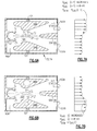
- the internal features adjust the internal cooling flow characteristics in response to an operating condition as represented graphically by flow distributions at stations (i) and (i + 1).
- an RMC microcircuit 90B formed within the liner panel 72A, 74A supplements the internal features as discussed above with cooling enhancement features such as pedestals 106A, followed by flow straighteners 106B formed in the passage 108 upstream of slot film cooling openings 110 (also shown in Figure 9 ).
- These relatively small cooling enhancement features are structures formed within the passage 108 to further affect the flow and are readily manufactured through refractory metal core technology in a manner commensurate with the islands 94A, 94B.
- a multiple of laser holes 112 may be located at strategic locations ahead of relatively larger internal features.
- the feedback features 100A', 100B' define a metering area between the internal features and the cooling enhancement features 104.
- the indented feedback features 100A', 100B' also provide a location for a dilution hole 88'.
- the flow separator island 98' may define a mount for the fastener F which supports the liner panel 72A, 74A ( Figure 10 ).
- the RMC microcircuits 90 provide effective cooling to address gas temperature variations inside the combustor chamber; enhance cooling through flow distribution with heat transfer enhancement features while maintaining increased film coverage and effectiveness throughout the combustor chamber; improve combustor durability by optimum distribution of cooling circuits; and facilitate lower emissions and improved turbine durability.
Landscapes
- Engineering & Computer Science (AREA)
- Chemical & Material Sciences (AREA)
- Combustion & Propulsion (AREA)
- Mechanical Engineering (AREA)
- General Engineering & Computer Science (AREA)
- Turbine Rotor Nozzle Sealing (AREA)
- Molds, Cores, And Manufacturing Methods Thereof (AREA)
Abstract
Description
- The present disclosure relates to a combustor, and more particularly to a cooling arrangement therefor.
- Gas turbine combustors have evolved to full hoop shells with attached heat shield combustor liner panels. The liner panels may have relatively low durability due to local hot spots that may cause high stress and cracking. Hot spots are conventionally combated with additional cooling air, however, this may have a potential negative effect on combustor emissions, pattern factor, and profile.
- Current combustor field distresses indicate hot spots at junctions and lips. Hot spots may occur at front heat shield panels and, in some instances, field distress propagates downstream towards the front liner panels. The distress may be accentuated in local regions where dedicated cooling is restricted due to space limitations. Hot spots may also appear in regions downstream of diffusion quench holes. In general, although effective, a typical combustor chamber environment includes large temperature gradients at different planes distributed axially throughout the combustor chamber.
- A combustor component of a gas turbine engine according to an exemplary aspect of the present disclosure includes a liner panel with a refractory metal core (RMC) microcircuit which provides a self-regulating feedback. The microcircuit therefore may comprise a feedback feature. The liner panel may be a forward liner panel. One embodiment microcircuit disclosed comprises first and second divergent islands, a flow separator island between the divergent islands and first and second feedback features.
- A method of cooling a combustor of a gas turbine engine according to an exemplary aspect of the present disclosure includes self regulating a cooling flow through a refractory metal core (RMC) microcircuit within a heat shield.
- Various features will become apparent to those skilled in the art from the following detailed description of the disclosed non-limiting embodiment. The drawings that accompany the detailed description can be briefly described as follows:
-
Figure 1 is a schematic cross-section of a gas turbine engine; -
Figure 2 is a perspective partial sectional view of an exemplary annular combustor that may be used with the gas turbine engine shown inFigure 1 ; -
Figure 3 is a cross-sectional view of an exemplary combustor that may be used with the gas turbine engine; -
Figure 4 is an expanded plan view of a microcircuit; -
Figure 5 is an expanded cross-sectional view of the microcircuit ofFigure 5 ; -
Figure 6A is a plan view of a first flow condition within the liner panel; -
Figure 6B is a plan view of a second flow condition within the liner panel; -
Figure 7A is a first example flow distribution which is unbalanced. -
Figure 7B is a second example flow distribution which is unbalanced and the reverse ofFigure 7A ; -
Figure 8 is a flow chart of microcircuit operation; -
Figure 9 is a planar view of another microcircuit; and -
Figure 10 is a sectional view of the microcircuit ofFigure 9 . -
Figure 1 schematically illustrates agas turbine engine 20. Thegas turbine engine 20 is disclosed herein as a two-spool turbofan that generally incorporates afan section 22, acompressor section 24, acombustor section 26 and aturbine section 28. Alternative engines might include an augmentor section (not shown) among other systems or features. Thefan section 22 drives air along a bypass flowpath while thecompressor section 24 drives air along a core flowpath for compression and communication into thecombustor section 26 then expansion through theturbine section 28. Although depicted as a turbofan gas turbine engine in the disclosed non-limiting embodiment, it should be understood that the concepts described herein are not limited to use with turbofans as the teachings may be applied to other types of turbine engines. - The
engine 20 generally includes alow speed spool 30 and ahigh speed spool 32 mounted for rotation about an engine central longitudinal axis A relative to an enginestatic structure 36 viaseveral bearing systems 38. It should be understood thatvarious bearing systems 38 at various locations may alternatively or additionally be provided. - The
low speed spool 30 generally includes aninner shaft 40 that interconnects afan 42, alow pressure compressor 44 and alow pressure turbine 46. Theinner shaft 40 is connected to thefan 42 through a gearedarchitecture 48 to drive thefan 42 at a lower speed than thelow speed spool 30. Thehigh speed spool 32 includes anouter shaft 50 that interconnects ahigh pressure compressor 52 andhigh pressure turbine 54. Acombustor 56 is arranged between thehigh pressure compressor 52 and thehigh pressure turbine 54. Theinner shaft 40 and theouter shaft 50 are concentric and rotate about the engine central longitudinal axis A which is collinear with their longitudinal axes. - The core airflow is compressed by the
low pressure compressor 44 then thehigh pressure compressor 52, mixed and burned with fuel within thecombustor 56, then expanded over thehigh pressure turbine 54 andlow pressure turbine 46. Theturbines low speed spool 30 andhigh speed spool 32 in response to the expansion. - With reference to
Figure 2 , thecombustor 56 generally includes anouter combustor liner 60 and aninner combustor liner 62. Theouter combustor liner 60 and theinner combustor liner 62 are spaced inward from acombustor case 64 such that acombustion chamber 66 is defined there between. Thecombustion chamber 66 is generally annular in shape and is defined betweencombustor liners - The
outer combustor liner 60 and thecombustor case 64 define an outerannular passageway 76 and theinner combustor liner 62 and thecombustor case 64 define an innerannular passageway 78. It should be understood that although a particular combustor is illustrated, other combustor types with various combustor liner panel arrangements will also benefit herefrom. It should be further understood that the disclosed cooling flow paths are but an illustrated embodiment and should not be limited only thereto. - With reference to
Figure 3 , thecombustor liners turbine section 28. Eachcombustor liner support shell respective support shell - In the disclosed non-limiting embodiment, the
combustor 56 includesforward liner panels 72F andaft liner panels 72A that line the hot side of theouter shell 68 withforward liner panels 74F andaft liner panels 74A that line the hot side of theinner shell 70. Fastener assemblies F such as studs and nuts may be used to connect each of the liner panels 72, 74 to the respective inner andouter shells - The
combustor 56 may also includeheat shield panels 80 that are radially arranged and generally transverse to the liner panels 72, 74. Eachheat shield panel 80 surrounds afuel injector 82 which is mounted within adome 69 which connects the respective inner andouter support shells - A cooling arrangement disclosed herein may generally include a multiple of
impingement cooling holes 84,film cooling holes 86,dilution holes 88 and refractory metal core (RMC) microcircuits 90 (illustrated schematically). Theimpingement cooling holes 84 penetrate through the inner andouter support shells outer support shells film cooling holes 86 penetrate each of the liner panels 72, 74 to promote the formation of a film of cooling air for effusion cooling. Thedilution holes 88 penetrate both the inner andouter support shells - Referring to
Figures 3-5 , theRMC microcircuits 90 may be selectively formed within the liner panels 72, 74 through a refractory metal core process. Refractory metal cores (RMCs) are typically metal-based casting cores usually composed of molybdenum with a protective coating. The refractory metal provides more ductility than conventional ceramic core materials while the coating - usually ceramic - protects the refractory metal from oxidation during a shell fire step of the investment casting process and prevents dissolution of the core from molten metal. The refractory metal core process allows small features to be cast inside internal passages, not possible, by ceramic cores. This, in turn, allows advanced cooling concepts, through the design space with relatively lower cooling flows as compared to current technology cooling flow levels. - RMC technology facilitates the manufacture of very small cast features such that the cooling supply flow may be minimized. As the cooling supply flow decreases, it may be beneficial to minimize any flow arrangement that may not operate at the highest level of optimization. Therefore, the design of the RMC microcircuit may beneficially optimize flow distribution by sensing external operating conditions.
- With reference to
Figure 4 , anRMC microcircuit 90A according to one non-limiting embodiment is formed within the liner panel 72, 74. In the disclosed non-limiting embodiment, the height (Figure 5 ) of theRMC microcircuit 90A may be in the range of 0.012 - 0.025 inches (0.030 - 0.064 cm) for each location within each liner panel 72, 74. That is, the liner panel 72, 74 includes the disclosed internal features which are formed via RMC technology. It should be understood that various heights may alternatively or additionally be provided. - Referring to
Figures 4 and 5 , theRMC microcircuit 90A includes a multiple of internal features located within the generally rectilinear liner panel 72, 74. The internal features may generally include asemi-circular inlet 92, a firstdivergent island 94A, a seconddivergent island 94B, aflow separator island 98, afirst feedback feature 100A, asecond feedback feature 100B, afirst slot exit 102A and asecond slot exit 102B (also shown inFigure 5 ). Generally, the firstdivergent island 94A, the seconddivergent island 94B, theflow separator island 98, thefirst feedback feature 100A, and thesecond feedback feature 100B are structures formed by theRMC microcircuit 90A which guide and direct the secondary flow as described herein within coolingchannel 104 formed within the liner panel 72, 74. That is, the structures form flows such as a self-regulating feedback which is further described herein below. Thesemi-circular inlet 92, thefirst slot exit 102A and thesecond slot exit 102B provide communication into or out of theRMC microcircuit 90A. That is, the liner panel 72, 74semi-circular inlet 92, thefirst slot exit 102A and thesecond slot exit 102B provide communication from within the liner panel 72, 74 to thecombustor chamber 66. - In this non-limiting embodiment, the
semi-circular inlet 92 and theflow separator island 98 are located along an axis P. The firstdivergent island 94A may define a location for adilution hole 88 which extends therethrough. The seconddivergent island 94B may define a mount for the fastener F which supports the liner panel 72, 74 (Figure 5 ). It should be understood that other arrangements of internal features, fastener and hole locations may alternatively or additionally be provided. - With reference to
Figure 6A , afeedback feature semi-circular inlet 92 forces the secondary cooling air S to spread into acooling channel 104. Thechannel 104 distributes thedivergent islands - If the secondary cooling air S flow velocity is uniform within the
channel 104 formed byislands exit slots Figures 6A, 6B ). InFigure 6A , an example flow distribution (Figure 7A ) is illustrated when the secondary cooling air S flow velocities increase towards theslot exit 102A (station (i+1)). The reverse occurs inFigure 6B as the main secondary cooling air S flow velocities increases towards theslot exit 102B (station (i)). This effect attenuates potential hot streaks in the main secondary cooling air S flow through increased film cooling where required (Figure 7B ). That is, the self regulating feedback flows S1, S2 sense the effects of the sink pressure changes and influences flow of the main secondary cooling air S distribution to address the fluctuations and balance in a self-regulating manner (Figure 8 ). The transfer of flow control is derived from sensing the sink pressure variations at the microcircuit exit. The flow rate within the microcircuit is inversely proportional to the sink pressure variations. As a result, the feedback flow returns to the beginning of the circuit, which then directs the main flow to the flow branch whose exit has a relative higher sink pressure. This provides a self-regulating action in the circuit without any moving parts. - With reference to
Figure 9 , anRMC microcircuit 90B according to another non-limiting embodiment, formed within theliner panel pedestals 106A, followed byflow straighteners 106B formed in thepassage 108 upstream of slot film cooling openings 110 (also shown inFigure 9 ). These relatively small cooling enhancement features are structures formed within thepassage 108 to further affect the flow and are readily manufactured through refractory metal core technology in a manner commensurate with theislands - In this non-limiting embodiment, the feedback features 100A', 100B' define a metering area between the internal features and the cooling enhancement features 104. The indented feedback features 100A', 100B' also provide a location for a dilution hole 88'. The flow separator island 98' may define a mount for the fastener F which supports the
liner panel Figure 10 ). - The RMC microcircuits 90 provide effective cooling to address gas temperature variations inside the combustor chamber; enhance cooling through flow distribution with heat transfer enhancement features while maintaining increased film coverage and effectiveness throughout the combustor chamber; improve combustor durability by optimum distribution of cooling circuits; and facilitate lower emissions and improved turbine durability.
- It should be understood that relative positional terms such as "forward," "aft," "upper," "lower," "above," "below," and the like are with reference to the normal operational attitude of the vehicle and should not be considered otherwise limiting.
- It should be understood that like reference numerals identify corresponding or similar elements throughout the several drawings. It should also be understood that although a particular component arrangement is disclosed in the illustrated embodiment, other arrangements will benefit herefrom.
- Although particular step sequences are shown, described, and claimed, it should be understood that steps may be performed in any order, separated or combined unless otherwise indicated and will still benefit from the present disclosure.
- The foregoing description is exemplary rather than defined by the limitations within. Various non-limiting embodiments are disclosed herein, however, one of ordinary skill in the art would recognize that various modifications and variations in light of the above teachings will fall within the scope of the appended claims. It is therefore to be understood that within the scope of the appended claims, the disclosure may be practiced other than as specifically described. For that reason the appended claims should be studied to determine true scope and content.
Claims (15)
- A combustor component of a gas turbine engine comprising:a liner panel (72,74) with a refractory metal core (RMC) microcircuit (90) which provides a self regulating feedback.
- The combustor component as recited in claim 1, wherein said liner panel is a generally planar forward liner panel (72F,74F).
- The combustor component as recited in claim 1 or 2, wherein said RMC microcircuit (90) includes a semi-circular inlet (92).
- The combustor component as recited in claim 1, 2 or 3, wherein said RMC microcircuit (90) forms at least one divergent island (94A,94B).
- The combustor component as recited in claim 4, further comprising a fastener (F) which mounts through said divergent island (94A) to support said liner panel (72,74) to a shell (68,70), and further optionally comprising a combustor case (64), said shell (68,70) mounted to said combustor case (64).
- The combustor component as recited in claim 4, wherein said RMC microcircuit (90A;90B) forms a first divergent island (94A) and a second divergent island (94B).
- The combustor component as recited in claim 6, further comprising a flow separator island (98;98') between said first divergent island (94A) and said second divergent island (94B).
- The combustor component as recited in claim 7, further comprising a semi-circular inlet (92) defined along an axis which intersects said flow separator island (98;98').
- The combustor component as recited in claim 7 or 8, further comprising a fastener (F) which mounts through said first divergent island (94A) to support said liner panel (72,74) to a shell, and/or a dilution hole (88) which penetrates through said second divergent island (94B).
- The combustor component as recited in claim 7, 8 or 9, further comprising a multiple of cooling enhancement features (104) downstream of said flow separator island (98').
- The combustor component as recited in claim 10, wherein said multiple of cooling enhancement features include pedestals (106A) and/or flow straighteners (106B) and/or laser holes (112).
- The combustor component as recited in claim 10 or 11, further comprising a multiple of exit slots (110) downstream of said flow separator island (98').
- A method of cooling a combustor of a gas turbine engine comprising:self-regulating a cooling flow through a refractory metal core (RMC) microcircuit (90) within a liner (72,74).
- The method as recited in claim 13, further comprising self-regulating the cooling flow in response to a sink pressure.
- The method as recited in claim 13 or 14, wherein the self-regulating includes feeding back a first portion of the cooling flow through a first feedback loop (51) and a second portion of the cooling flow through a second feedback loop (52), wherein, optionally, a velocity imbalance between the first feedback loop (51) and the second feedback loop (52) modulates the cooling flow toward a side of said RMC microcircuit (90).
Applications Claiming Priority (1)
| Application Number | Priority Date | Filing Date | Title |
|---|---|---|---|
| US13/193,686 US8978385B2 (en) | 2011-07-29 | 2011-07-29 | Distributed cooling for gas turbine engine combustor |
Publications (3)
| Publication Number | Publication Date |
|---|---|
| EP2551593A2 true EP2551593A2 (en) | 2013-01-30 |
| EP2551593A3 EP2551593A3 (en) | 2017-05-17 |
| EP2551593B1 EP2551593B1 (en) | 2020-09-02 |
Family
ID=46639350
Family Applications (1)
| Application Number | Title | Priority Date | Filing Date |
|---|---|---|---|
| EP12178491.2A Active EP2551593B1 (en) | 2011-07-29 | 2012-07-30 | Distributed cooling for gas turbine engine combustor |
Country Status (2)
| Country | Link |
|---|---|
| US (1) | US8978385B2 (en) |
| EP (1) | EP2551593B1 (en) |
Cited By (13)
| Publication number | Priority date | Publication date | Assignee | Title |
|---|---|---|---|---|
| WO2014164429A1 (en) * | 2013-03-13 | 2014-10-09 | Rolls-Royce North American Technologies, Inc. | Check valve for propulsive engine combustion chamber |
| US9579714B1 (en) | 2015-12-17 | 2017-02-28 | General Electric Company | Method and assembly for forming components having internal passages using a lattice structure |
| US9968991B2 (en) | 2015-12-17 | 2018-05-15 | General Electric Company | Method and assembly for forming components having internal passages using a lattice structure |
| US9987677B2 (en) | 2015-12-17 | 2018-06-05 | General Electric Company | Method and assembly for forming components having internal passages using a jacketed core |
| US10046389B2 (en) | 2015-12-17 | 2018-08-14 | General Electric Company | Method and assembly for forming components having internal passages using a jacketed core |
| US10099276B2 (en) | 2015-12-17 | 2018-10-16 | General Electric Company | Method and assembly for forming components having an internal passage defined therein |
| US10099283B2 (en) | 2015-12-17 | 2018-10-16 | General Electric Company | Method and assembly for forming components having an internal passage defined therein |
| US10099284B2 (en) | 2015-12-17 | 2018-10-16 | General Electric Company | Method and assembly for forming components having a catalyzed internal passage defined therein |
| US10118217B2 (en) | 2015-12-17 | 2018-11-06 | General Electric Company | Method and assembly for forming components having internal passages using a jacketed core |
| US10137499B2 (en) | 2015-12-17 | 2018-11-27 | General Electric Company | Method and assembly for forming components having an internal passage defined therein |
| US10150158B2 (en) | 2015-12-17 | 2018-12-11 | General Electric Company | Method and assembly for forming components having internal passages using a jacketed core |
| US10286450B2 (en) | 2016-04-27 | 2019-05-14 | General Electric Company | Method and assembly for forming components using a jacketed core |
| US10335853B2 (en) | 2016-04-27 | 2019-07-02 | General Electric Company | Method and assembly for forming components using a jacketed core |
Families Citing this family (31)
| Publication number | Priority date | Publication date | Assignee | Title |
|---|---|---|---|---|
| US9243801B2 (en) * | 2012-06-07 | 2016-01-26 | United Technologies Corporation | Combustor liner with improved film cooling |
| EP2738469B1 (en) * | 2012-11-30 | 2019-04-17 | Ansaldo Energia IP UK Limited | Combustor part of a gas turbine comprising a near wall cooling arrangement |
| EP2965010B1 (en) * | 2013-03-05 | 2018-10-17 | Rolls-Royce Corporation | Dual-wall impingement, convection, effusion combustor tile |
| US9694277B2 (en) | 2013-03-14 | 2017-07-04 | Microsoft Technology Licensing, Llc | Client side processing of character interactions in a remote gaming environment |
| EP3039347B1 (en) | 2013-08-30 | 2019-10-23 | United Technologies Corporation | Gas turbine engine wall assembly with support shell contour regions |
| EP3922829B1 (en) | 2013-09-16 | 2023-11-08 | RTX Corporation | Gas turbine engine combustion chamber wall assembly comprising cooling holes through transverse structure |
| EP3047128B1 (en) * | 2013-09-16 | 2018-10-31 | United Technologies Corporation | Controlled variation of pressure drop through effusion cooling in a double walled combustor of a gas turbine engine |
| SG11201602178QA (en) * | 2013-11-01 | 2016-05-30 | United Technologies Corp | Tool for removing collars |
| US10473330B2 (en) | 2013-11-18 | 2019-11-12 | United Technologies Corporation | Swept combustor liner panels for gas turbine engine combustor |
| EP3084310A4 (en) | 2013-12-19 | 2017-01-04 | United Technologies Corporation | Gas turbine engine wall assembly with circumferential rail stud architecture |
| WO2015116360A1 (en) * | 2014-01-30 | 2015-08-06 | United Technologies Corporation | Cooling flow for leading panel in a gas turbine engine combustor |
| EP3102884B1 (en) * | 2014-02-03 | 2020-04-01 | United Technologies Corporation | Stepped heat shield for a turbine engine combustor |
| US10533745B2 (en) | 2014-02-03 | 2020-01-14 | United Technologies Corporation | Film cooling a combustor wall of a turbine engine |
| EP3105425B1 (en) * | 2014-02-13 | 2019-03-20 | United Technologies Corporation | Gas turbine engine component cooling circuit with respirating pedestal |
| US10300526B2 (en) | 2014-02-28 | 2019-05-28 | United Technologies Corporation | Core assembly including studded spacer |
| US9851105B2 (en) | 2014-07-03 | 2017-12-26 | United Technologies Corporation | Self-cooled orifice structure |
| EP2977679B1 (en) | 2014-07-22 | 2019-08-28 | United Technologies Corporation | Combustor wall for a gas turbine engine and method of acoustic dampening |
| EP2995863B1 (en) * | 2014-09-09 | 2018-05-23 | United Technologies Corporation | Single-walled combustor for a gas turbine engine and method of manufacture |
| US10731857B2 (en) * | 2014-09-09 | 2020-08-04 | Raytheon Technologies Corporation | Film cooling circuit for a combustor liner |
| US10746403B2 (en) | 2014-12-12 | 2020-08-18 | Raytheon Technologies Corporation | Cooled wall assembly for a combustor and method of design |
| GB201501817D0 (en) * | 2015-02-04 | 2015-03-18 | Rolls Royce Plc | A combustion chamber and a combustion chamber segment |
| US10101029B2 (en) * | 2015-03-30 | 2018-10-16 | United Technologies Corporation | Combustor panels and configurations for a gas turbine engine |
| US9803863B2 (en) | 2015-05-13 | 2017-10-31 | Solar Turbines Incorporated | Controlled-leak combustor grommet |
| US10690347B2 (en) | 2017-02-01 | 2020-06-23 | General Electric Company | CMC combustor deflector |
| DE102017202177A1 (en) * | 2017-02-10 | 2018-08-16 | Rolls-Royce Deutschland Ltd & Co Kg | Wall component of a gas turbine with improved cooling |
| US10663168B2 (en) * | 2017-08-02 | 2020-05-26 | Raytheon Technologies Corporation | End rail mate-face low pressure vortex minimization |
| US10940529B2 (en) | 2017-09-12 | 2021-03-09 | Raytheon Technologies Corporation | Method to produce jet engine combustor heat shield panels assembly |
| US11029031B2 (en) * | 2018-08-02 | 2021-06-08 | Raytheon Technologies Corporation | Tapered panel rail |
| US10953461B2 (en) | 2019-03-21 | 2021-03-23 | Raytheon Technologies Corporation | Investment casting method including forming of investment casting core |
| US11262077B2 (en) * | 2019-09-20 | 2022-03-01 | Raytheon Technologies Corporation | Spall plate for consumable combustor support structures |
| US20230055939A1 (en) * | 2021-08-20 | 2023-02-23 | Raytheon Technologies Corporation | Multi-function monolithic combustion liner |
Family Cites Families (14)
| Publication number | Priority date | Publication date | Assignee | Title |
|---|---|---|---|---|
| US4838031A (en) * | 1987-08-06 | 1989-06-13 | Avco Corporation | Internally cooled combustion chamber liner |
| US5687572A (en) * | 1992-11-02 | 1997-11-18 | Alliedsignal Inc. | Thin wall combustor with backside impingement cooling |
| US5421158A (en) * | 1994-10-21 | 1995-06-06 | General Electric Company | Segmented centerbody for a double annular combustor |
| US5584651A (en) * | 1994-10-31 | 1996-12-17 | General Electric Company | Cooled shroud |
| US5737922A (en) | 1995-01-30 | 1998-04-14 | Aerojet General Corporation | Convectively cooled liner for a combustor |
| US5782294A (en) * | 1995-12-18 | 1998-07-21 | United Technologies Corporation | Cooled liner apparatus |
| US6402470B1 (en) * | 1999-10-05 | 2002-06-11 | United Technologies Corporation | Method and apparatus for cooling a wall within a gas turbine engine |
| GB0029337D0 (en) * | 2000-12-01 | 2001-01-17 | Rolls Royce Plc | A seal segment for a turbine |
| US7093439B2 (en) * | 2002-05-16 | 2006-08-22 | United Technologies Corporation | Heat shield panels for use in a combustor for a gas turbine engine |
| US7137776B2 (en) | 2002-06-19 | 2006-11-21 | United Technologies Corporation | Film cooling for microcircuits |
| US6705831B2 (en) | 2002-06-19 | 2004-03-16 | United Technologies Corporation | Linked, manufacturable, non-plugging microcircuits |
| US6896487B2 (en) * | 2003-08-08 | 2005-05-24 | United Technologies Corporation | Microcircuit airfoil mainbody |
| US20050087319A1 (en) * | 2003-10-16 | 2005-04-28 | Beals James T. | Refractory metal core wall thickness control |
| US7775053B2 (en) * | 2004-09-20 | 2010-08-17 | United Technologies Corporation | Heat transfer augmentation in a compact heat exchanger pedestal array |
-
2011
- 2011-07-29 US US13/193,686 patent/US8978385B2/en active Active
-
2012
- 2012-07-30 EP EP12178491.2A patent/EP2551593B1/en active Active
Non-Patent Citations (1)
| Title |
|---|
| None |
Cited By (17)
| Publication number | Priority date | Publication date | Assignee | Title |
|---|---|---|---|---|
| WO2014164429A1 (en) * | 2013-03-13 | 2014-10-09 | Rolls-Royce North American Technologies, Inc. | Check valve for propulsive engine combustion chamber |
| US9551299B2 (en) | 2013-03-13 | 2017-01-24 | Rolls-Royce Corporation | Check valve for propulsive engine combustion chamber |
| EP2971971B1 (en) * | 2013-03-13 | 2018-11-28 | Rolls-Royce North American Technologies, Inc. | Check valve for propulsive engine combustion chamber |
| US9975176B2 (en) | 2015-12-17 | 2018-05-22 | General Electric Company | Method and assembly for forming components having internal passages using a lattice structure |
| US10118217B2 (en) | 2015-12-17 | 2018-11-06 | General Electric Company | Method and assembly for forming components having internal passages using a jacketed core |
| US9987677B2 (en) | 2015-12-17 | 2018-06-05 | General Electric Company | Method and assembly for forming components having internal passages using a jacketed core |
| US10046389B2 (en) | 2015-12-17 | 2018-08-14 | General Electric Company | Method and assembly for forming components having internal passages using a jacketed core |
| US10099276B2 (en) | 2015-12-17 | 2018-10-16 | General Electric Company | Method and assembly for forming components having an internal passage defined therein |
| US10099283B2 (en) | 2015-12-17 | 2018-10-16 | General Electric Company | Method and assembly for forming components having an internal passage defined therein |
| US10099284B2 (en) | 2015-12-17 | 2018-10-16 | General Electric Company | Method and assembly for forming components having a catalyzed internal passage defined therein |
| US9968991B2 (en) | 2015-12-17 | 2018-05-15 | General Electric Company | Method and assembly for forming components having internal passages using a lattice structure |
| US10137499B2 (en) | 2015-12-17 | 2018-11-27 | General Electric Company | Method and assembly for forming components having an internal passage defined therein |
| US9579714B1 (en) | 2015-12-17 | 2017-02-28 | General Electric Company | Method and assembly for forming components having internal passages using a lattice structure |
| US10150158B2 (en) | 2015-12-17 | 2018-12-11 | General Electric Company | Method and assembly for forming components having internal passages using a jacketed core |
| US10286450B2 (en) | 2016-04-27 | 2019-05-14 | General Electric Company | Method and assembly for forming components using a jacketed core |
| US10335853B2 (en) | 2016-04-27 | 2019-07-02 | General Electric Company | Method and assembly for forming components using a jacketed core |
| US10981221B2 (en) | 2016-04-27 | 2021-04-20 | General Electric Company | Method and assembly for forming components using a jacketed core |
Also Published As
| Publication number | Publication date |
|---|---|
| US8978385B2 (en) | 2015-03-17 |
| US20130025287A1 (en) | 2013-01-31 |
| EP2551593B1 (en) | 2020-09-02 |
| EP2551593A3 (en) | 2017-05-17 |
Similar Documents
| Publication | Publication Date | Title |
|---|---|---|
| EP2551593B1 (en) | Distributed cooling for gas turbine engine combustor | |
| EP2551592B1 (en) | Microcircuit cooling for gas turbine engine combustor | |
| US11280268B2 (en) | Cooled fuel injector system for a gas turbine engine and a method for operating the same | |
| EP3033508B1 (en) | Cooled fuel injector system for a gas turbine engine | |
| US10400672B2 (en) | Cooled fuel injector system for a gas turbine engine | |
| US11073284B2 (en) | Cooled grommet for a combustor wall assembly | |
| US20160313005A1 (en) | Additive manufactured combustor heat shield with cooled attachment stud | |
| US11112115B2 (en) | Contoured dilution passages for gas turbine engine combustor | |
| EP2551594B1 (en) | Temperature mixing enhancement with locally co-swirling quench jet pattern for gas turbine engine combustor | |
| US10935240B2 (en) | Additive manufactured combustor heat shield | |
| US10247419B2 (en) | Combustor liner panel with a multiple of heat transfer ribs for a gas turbine engine combustor | |
| US20140096527A1 (en) | Gas turbine engine combustor liner | |
| EP2932070B1 (en) | Gas turbine engine combustor heat shield with increased film cooling effectiveness | |
| US10788210B2 (en) | Single-walled combustor for a gas turbine engine and method of manufacture | |
| US10731857B2 (en) | Film cooling circuit for a combustor liner | |
| US20150260399A1 (en) | Combustor section of a gas turbine engine | |
| US10775044B2 (en) | Gas turbine engine dual-wall hot section structure | |
| US10281152B2 (en) | Thermal mechanical dimple array for a combustor wall assembly |
Legal Events
| Date | Code | Title | Description |
|---|---|---|---|
| PUAI | Public reference made under article 153(3) epc to a published international application that has entered the european phase |
Free format text: ORIGINAL CODE: 0009012 |
|
| AK | Designated contracting states |
Kind code of ref document: A2 Designated state(s): AL AT BE BG CH CY CZ DE DK EE ES FI FR GB GR HR HU IE IS IT LI LT LU LV MC MK MT NL NO PL PT RO RS SE SI SK SM TR |
|
| AX | Request for extension of the european patent |
Extension state: BA ME |
|
| RAP1 | Party data changed (applicant data changed or rights of an application transferred) |
Owner name: UNITED TECHNOLOGIES CORPORATION |
|
| PUAL | Search report despatched |
Free format text: ORIGINAL CODE: 0009013 |
|
| AK | Designated contracting states |
Kind code of ref document: A3 Designated state(s): AL AT BE BG CH CY CZ DE DK EE ES FI FR GB GR HR HU IE IS IT LI LT LU LV MC MK MT NL NO PL PT RO RS SE SI SK SM TR |
|
| AX | Request for extension of the european patent |
Extension state: BA ME |
|
| RIC1 | Information provided on ipc code assigned before grant |
Ipc: F23R 3/06 20060101ALI20170411BHEP Ipc: F23R 3/00 20060101AFI20170411BHEP |
|
| STAA | Information on the status of an ep patent application or granted ep patent |
Free format text: STATUS: REQUEST FOR EXAMINATION WAS MADE |
|
| 17P | Request for examination filed |
Effective date: 20171117 |
|
| RBV | Designated contracting states (corrected) |
Designated state(s): AL AT BE BG CH CY CZ DE DK EE ES FI FR GB GR HR HU IE IS IT LI LT LU LV MC MK MT NL NO PL PT RO RS SE SI SK SM TR |
|
| STAA | Information on the status of an ep patent application or granted ep patent |
Free format text: STATUS: EXAMINATION IS IN PROGRESS |
|
| 17Q | First examination report despatched |
Effective date: 20190313 |
|
| GRAP | Despatch of communication of intention to grant a patent |
Free format text: ORIGINAL CODE: EPIDOSNIGR1 |
|
| STAA | Information on the status of an ep patent application or granted ep patent |
Free format text: STATUS: GRANT OF PATENT IS INTENDED |
|
| INTG | Intention to grant announced |
Effective date: 20200228 |
|
| GRAS | Grant fee paid |
Free format text: ORIGINAL CODE: EPIDOSNIGR3 |
|
| GRAA | (expected) grant |
Free format text: ORIGINAL CODE: 0009210 |
|
| STAA | Information on the status of an ep patent application or granted ep patent |
Free format text: STATUS: THE PATENT HAS BEEN GRANTED |
|
| AK | Designated contracting states |
Kind code of ref document: B1 Designated state(s): AL AT BE BG CH CY CZ DE DK EE ES FI FR GB GR HR HU IE IS IT LI LT LU LV MC MK MT NL NO PL PT RO RS SE SI SK SM TR |
|
| REG | Reference to a national code |
Ref country code: GB Ref legal event code: FG4D |
|
| REG | Reference to a national code |
Ref country code: AT Ref legal event code: REF Ref document number: 1309264 Country of ref document: AT Kind code of ref document: T Effective date: 20200915 Ref country code: CH Ref legal event code: EP |
|
| REG | Reference to a national code |
Ref country code: DE Ref legal event code: R096 Ref document number: 602012072069 Country of ref document: DE |
|
| REG | Reference to a national code |
Ref country code: IE Ref legal event code: FG4D |
|
| REG | Reference to a national code |
Ref country code: LT Ref legal event code: MG4D |
|
| PG25 | Lapsed in a contracting state [announced via postgrant information from national office to epo] |
Ref country code: NO Free format text: LAPSE BECAUSE OF FAILURE TO SUBMIT A TRANSLATION OF THE DESCRIPTION OR TO PAY THE FEE WITHIN THE PRESCRIBED TIME-LIMIT Effective date: 20201202 Ref country code: BG Free format text: LAPSE BECAUSE OF FAILURE TO SUBMIT A TRANSLATION OF THE DESCRIPTION OR TO PAY THE FEE WITHIN THE PRESCRIBED TIME-LIMIT Effective date: 20201202 Ref country code: SE Free format text: LAPSE BECAUSE OF FAILURE TO SUBMIT A TRANSLATION OF THE DESCRIPTION OR TO PAY THE FEE WITHIN THE PRESCRIBED TIME-LIMIT Effective date: 20200902 Ref country code: GR Free format text: LAPSE BECAUSE OF FAILURE TO SUBMIT A TRANSLATION OF THE DESCRIPTION OR TO PAY THE FEE WITHIN THE PRESCRIBED TIME-LIMIT Effective date: 20201203 Ref country code: LT Free format text: LAPSE BECAUSE OF FAILURE TO SUBMIT A TRANSLATION OF THE DESCRIPTION OR TO PAY THE FEE WITHIN THE PRESCRIBED TIME-LIMIT Effective date: 20200902 Ref country code: HR Free format text: LAPSE BECAUSE OF FAILURE TO SUBMIT A TRANSLATION OF THE DESCRIPTION OR TO PAY THE FEE WITHIN THE PRESCRIBED TIME-LIMIT Effective date: 20200902 Ref country code: FI Free format text: LAPSE BECAUSE OF FAILURE TO SUBMIT A TRANSLATION OF THE DESCRIPTION OR TO PAY THE FEE WITHIN THE PRESCRIBED TIME-LIMIT Effective date: 20200902 |
|
| REG | Reference to a national code |
Ref country code: NL Ref legal event code: MP Effective date: 20200902 |
|
| REG | Reference to a national code |
Ref country code: AT Ref legal event code: MK05 Ref document number: 1309264 Country of ref document: AT Kind code of ref document: T Effective date: 20200902 |
|
| PG25 | Lapsed in a contracting state [announced via postgrant information from national office to epo] |
Ref country code: RS Free format text: LAPSE BECAUSE OF FAILURE TO SUBMIT A TRANSLATION OF THE DESCRIPTION OR TO PAY THE FEE WITHIN THE PRESCRIBED TIME-LIMIT Effective date: 20200902 Ref country code: PL Free format text: LAPSE BECAUSE OF FAILURE TO SUBMIT A TRANSLATION OF THE DESCRIPTION OR TO PAY THE FEE WITHIN THE PRESCRIBED TIME-LIMIT Effective date: 20200902 Ref country code: LV Free format text: LAPSE BECAUSE OF FAILURE TO SUBMIT A TRANSLATION OF THE DESCRIPTION OR TO PAY THE FEE WITHIN THE PRESCRIBED TIME-LIMIT Effective date: 20200902 |
|
| RAP2 | Party data changed (patent owner data changed or rights of a patent transferred) |
Owner name: RAYTHEON TECHNOLOGIES CORPORATION |
|
| PG25 | Lapsed in a contracting state [announced via postgrant information from national office to epo] |
Ref country code: CZ Free format text: LAPSE BECAUSE OF FAILURE TO SUBMIT A TRANSLATION OF THE DESCRIPTION OR TO PAY THE FEE WITHIN THE PRESCRIBED TIME-LIMIT Effective date: 20200902 Ref country code: EE Free format text: LAPSE BECAUSE OF FAILURE TO SUBMIT A TRANSLATION OF THE DESCRIPTION OR TO PAY THE FEE WITHIN THE PRESCRIBED TIME-LIMIT Effective date: 20200902 Ref country code: NL Free format text: LAPSE BECAUSE OF FAILURE TO SUBMIT A TRANSLATION OF THE DESCRIPTION OR TO PAY THE FEE WITHIN THE PRESCRIBED TIME-LIMIT Effective date: 20200902 Ref country code: PT Free format text: LAPSE BECAUSE OF FAILURE TO SUBMIT A TRANSLATION OF THE DESCRIPTION OR TO PAY THE FEE WITHIN THE PRESCRIBED TIME-LIMIT Effective date: 20210104 Ref country code: SM Free format text: LAPSE BECAUSE OF FAILURE TO SUBMIT A TRANSLATION OF THE DESCRIPTION OR TO PAY THE FEE WITHIN THE PRESCRIBED TIME-LIMIT Effective date: 20200902 Ref country code: RO Free format text: LAPSE BECAUSE OF FAILURE TO SUBMIT A TRANSLATION OF THE DESCRIPTION OR TO PAY THE FEE WITHIN THE PRESCRIBED TIME-LIMIT Effective date: 20200902 |
|
| PG25 | Lapsed in a contracting state [announced via postgrant information from national office to epo] |
Ref country code: IS Free format text: LAPSE BECAUSE OF FAILURE TO SUBMIT A TRANSLATION OF THE DESCRIPTION OR TO PAY THE FEE WITHIN THE PRESCRIBED TIME-LIMIT Effective date: 20210102 Ref country code: ES Free format text: LAPSE BECAUSE OF FAILURE TO SUBMIT A TRANSLATION OF THE DESCRIPTION OR TO PAY THE FEE WITHIN THE PRESCRIBED TIME-LIMIT Effective date: 20200902 Ref country code: AL Free format text: LAPSE BECAUSE OF FAILURE TO SUBMIT A TRANSLATION OF THE DESCRIPTION OR TO PAY THE FEE WITHIN THE PRESCRIBED TIME-LIMIT Effective date: 20200902 Ref country code: AT Free format text: LAPSE BECAUSE OF FAILURE TO SUBMIT A TRANSLATION OF THE DESCRIPTION OR TO PAY THE FEE WITHIN THE PRESCRIBED TIME-LIMIT Effective date: 20200902 |
|
| REG | Reference to a national code |
Ref country code: DE Ref legal event code: R097 Ref document number: 602012072069 Country of ref document: DE |
|
| PG25 | Lapsed in a contracting state [announced via postgrant information from national office to epo] |
Ref country code: SK Free format text: LAPSE BECAUSE OF FAILURE TO SUBMIT A TRANSLATION OF THE DESCRIPTION OR TO PAY THE FEE WITHIN THE PRESCRIBED TIME-LIMIT Effective date: 20200902 |
|
| PLBE | No opposition filed within time limit |
Free format text: ORIGINAL CODE: 0009261 |
|
| STAA | Information on the status of an ep patent application or granted ep patent |
Free format text: STATUS: NO OPPOSITION FILED WITHIN TIME LIMIT |
|
| 26N | No opposition filed |
Effective date: 20210603 |
|
| PG25 | Lapsed in a contracting state [announced via postgrant information from national office to epo] |
Ref country code: SI Free format text: LAPSE BECAUSE OF FAILURE TO SUBMIT A TRANSLATION OF THE DESCRIPTION OR TO PAY THE FEE WITHIN THE PRESCRIBED TIME-LIMIT Effective date: 20200902 Ref country code: DK Free format text: LAPSE BECAUSE OF FAILURE TO SUBMIT A TRANSLATION OF THE DESCRIPTION OR TO PAY THE FEE WITHIN THE PRESCRIBED TIME-LIMIT Effective date: 20200902 |
|
| PG25 | Lapsed in a contracting state [announced via postgrant information from national office to epo] |
Ref country code: IT Free format text: LAPSE BECAUSE OF FAILURE TO SUBMIT A TRANSLATION OF THE DESCRIPTION OR TO PAY THE FEE WITHIN THE PRESCRIBED TIME-LIMIT Effective date: 20200902 |
|
| REG | Reference to a national code |
Ref country code: CH Ref legal event code: PL |
|
| PG25 | Lapsed in a contracting state [announced via postgrant information from national office to epo] |
Ref country code: MC Free format text: LAPSE BECAUSE OF FAILURE TO SUBMIT A TRANSLATION OF THE DESCRIPTION OR TO PAY THE FEE WITHIN THE PRESCRIBED TIME-LIMIT Effective date: 20200902 |
|
| REG | Reference to a national code |
Ref country code: BE Ref legal event code: MM Effective date: 20210731 |
|
| PG25 | Lapsed in a contracting state [announced via postgrant information from national office to epo] |
Ref country code: LI Free format text: LAPSE BECAUSE OF NON-PAYMENT OF DUE FEES Effective date: 20210731 Ref country code: CH Free format text: LAPSE BECAUSE OF NON-PAYMENT OF DUE FEES Effective date: 20210731 |
|
| PG25 | Lapsed in a contracting state [announced via postgrant information from national office to epo] |
Ref country code: LU Free format text: LAPSE BECAUSE OF NON-PAYMENT OF DUE FEES Effective date: 20210730 |
|
| PG25 | Lapsed in a contracting state [announced via postgrant information from national office to epo] |
Ref country code: IE Free format text: LAPSE BECAUSE OF NON-PAYMENT OF DUE FEES Effective date: 20210730 Ref country code: BE Free format text: LAPSE BECAUSE OF NON-PAYMENT OF DUE FEES Effective date: 20210731 |
|
| PG25 | Lapsed in a contracting state [announced via postgrant information from national office to epo] |
Ref country code: HU Free format text: LAPSE BECAUSE OF FAILURE TO SUBMIT A TRANSLATION OF THE DESCRIPTION OR TO PAY THE FEE WITHIN THE PRESCRIBED TIME-LIMIT; INVALID AB INITIO Effective date: 20120730 Ref country code: CY Free format text: LAPSE BECAUSE OF FAILURE TO SUBMIT A TRANSLATION OF THE DESCRIPTION OR TO PAY THE FEE WITHIN THE PRESCRIBED TIME-LIMIT Effective date: 20200902 |
|
| P01 | Opt-out of the competence of the unified patent court (upc) registered |
Effective date: 20230520 |
|
| PGFP | Annual fee paid to national office [announced via postgrant information from national office to epo] |
Ref country code: FR Payment date: 20230621 Year of fee payment: 12 |
|
| PGFP | Annual fee paid to national office [announced via postgrant information from national office to epo] |
Ref country code: GB Payment date: 20230620 Year of fee payment: 12 |
|
| PGFP | Annual fee paid to national office [announced via postgrant information from national office to epo] |
Ref country code: DE Payment date: 20230620 Year of fee payment: 12 |
|
| PG25 | Lapsed in a contracting state [announced via postgrant information from national office to epo] |
Ref country code: MK Free format text: LAPSE BECAUSE OF FAILURE TO SUBMIT A TRANSLATION OF THE DESCRIPTION OR TO PAY THE FEE WITHIN THE PRESCRIBED TIME-LIMIT Effective date: 20200902 |