EP2551190A1 - Convertiplane - Google Patents
Convertiplane Download PDFInfo
- Publication number
- EP2551190A1 EP2551190A1 EP11425208A EP11425208A EP2551190A1 EP 2551190 A1 EP2551190 A1 EP 2551190A1 EP 11425208 A EP11425208 A EP 11425208A EP 11425208 A EP11425208 A EP 11425208A EP 2551190 A1 EP2551190 A1 EP 2551190A1
- Authority
- EP
- European Patent Office
- Prior art keywords
- convertiplane
- relative
- semi
- wings
- rotors
- Prior art date
- Legal status (The legal status is an assumption and is not a legal conclusion. Google has not performed a legal analysis and makes no representation as to the accuracy of the status listed.)
- Granted
Links
- 230000007704 transition Effects 0.000 description 4
- RZVHIXYEVGDQDX-UHFFFAOYSA-N 9,10-anthraquinone Chemical compound C1=CC=C2C(=O)C3=CC=CC=C3C(=O)C2=C1 RZVHIXYEVGDQDX-UHFFFAOYSA-N 0.000 description 3
- 238000005452 bending Methods 0.000 description 3
- 238000002485 combustion reaction Methods 0.000 description 3
- 230000000694 effects Effects 0.000 description 3
- 230000004907 flux Effects 0.000 description 3
- 230000033001 locomotion Effects 0.000 description 3
- 125000004122 cyclic group Chemical group 0.000 description 2
- 230000007423 decrease Effects 0.000 description 2
- 230000003247 decreasing effect Effects 0.000 description 2
- 230000005484 gravity Effects 0.000 description 2
- 241000272517 Anseriformes Species 0.000 description 1
- 230000000712 assembly Effects 0.000 description 1
- 238000000429 assembly Methods 0.000 description 1
- 230000005540 biological transmission Effects 0.000 description 1
- 230000015572 biosynthetic process Effects 0.000 description 1
- 238000005755 formation reaction Methods 0.000 description 1
- 239000000446 fuel Substances 0.000 description 1
- 229910001416 lithium ion Inorganic materials 0.000 description 1
- 238000004519 manufacturing process Methods 0.000 description 1
- 230000002093 peripheral effect Effects 0.000 description 1
- 230000000007 visual effect Effects 0.000 description 1
Images


Classifications
-
- B—PERFORMING OPERATIONS; TRANSPORTING
- B64—AIRCRAFT; AVIATION; COSMONAUTICS
- B64C—AEROPLANES; HELICOPTERS
- B64C27/00—Rotorcraft; Rotors peculiar thereto
- B64C27/22—Compound rotorcraft, i.e. aircraft using in flight the features of both aeroplane and rotorcraft
-
- B—PERFORMING OPERATIONS; TRANSPORTING
- B64—AIRCRAFT; AVIATION; COSMONAUTICS
- B64C—AEROPLANES; HELICOPTERS
- B64C11/00—Propellers, e.g. of ducted type; Features common to propellers and rotors for rotorcraft
- B64C11/001—Shrouded propellers
-
- B—PERFORMING OPERATIONS; TRANSPORTING
- B64—AIRCRAFT; AVIATION; COSMONAUTICS
- B64C—AEROPLANES; HELICOPTERS
- B64C27/00—Rotorcraft; Rotors peculiar thereto
- B64C27/32—Rotors
- B64C27/46—Blades
- B64C27/467—Aerodynamic features
-
- B—PERFORMING OPERATIONS; TRANSPORTING
- B64—AIRCRAFT; AVIATION; COSMONAUTICS
- B64C—AEROPLANES; HELICOPTERS
- B64C29/00—Aircraft capable of landing or taking-off vertically, e.g. vertical take-off and landing [VTOL] aircraft
- B64C29/0008—Aircraft capable of landing or taking-off vertically, e.g. vertical take-off and landing [VTOL] aircraft having its flight directional axis horizontal when grounded
- B64C29/0016—Aircraft capable of landing or taking-off vertically, e.g. vertical take-off and landing [VTOL] aircraft having its flight directional axis horizontal when grounded the lift during taking-off being created by free or ducted propellers or by blowers
- B64C29/0033—Aircraft capable of landing or taking-off vertically, e.g. vertical take-off and landing [VTOL] aircraft having its flight directional axis horizontal when grounded the lift during taking-off being created by free or ducted propellers or by blowers the propellers being tiltable relative to the fuselage
-
- B—PERFORMING OPERATIONS; TRANSPORTING
- B64—AIRCRAFT; AVIATION; COSMONAUTICS
- B64C—AEROPLANES; HELICOPTERS
- B64C3/00—Wings
- B64C3/38—Adjustment of complete wings or parts thereof
- B64C3/54—Varying in area
-
- B—PERFORMING OPERATIONS; TRANSPORTING
- B64—AIRCRAFT; AVIATION; COSMONAUTICS
- B64C—AEROPLANES; HELICOPTERS
- B64C3/00—Wings
- B64C3/38—Adjustment of complete wings or parts thereof
- B64C3/56—Folding or collapsing to reduce overall dimensions of aircraft
-
- B—PERFORMING OPERATIONS; TRANSPORTING
- B64—AIRCRAFT; AVIATION; COSMONAUTICS
- B64C—AEROPLANES; HELICOPTERS
- B64C37/00—Convertible aircraft
-
- Y—GENERAL TAGGING OF NEW TECHNOLOGICAL DEVELOPMENTS; GENERAL TAGGING OF CROSS-SECTIONAL TECHNOLOGIES SPANNING OVER SEVERAL SECTIONS OF THE IPC; TECHNICAL SUBJECTS COVERED BY FORMER USPC CROSS-REFERENCE ART COLLECTIONS [XRACs] AND DIGESTS
- Y02—TECHNOLOGIES OR APPLICATIONS FOR MITIGATION OR ADAPTATION AGAINST CLIMATE CHANGE
- Y02T—CLIMATE CHANGE MITIGATION TECHNOLOGIES RELATED TO TRANSPORTATION
- Y02T50/00—Aeronautics or air transport
- Y02T50/10—Drag reduction
Definitions
- the present invention relates to a convertiplane, i.e. a hybrid aircraft with adjustable rotors, capable of selectively assuming an "aeroplane” configuration, in which the rotors are positioned with their axes substantially parallel to the longitudinal axis of the aircraft, and a "helicopter” configuration, in which the rotors are positioned with their axes substantially vertical and crosswise to the longitudinal axis of the aircraft, so as to combine the advantages of a fixed-wing turboprop aircraft and a helicopter.
- a convertiplane i.e. a hybrid aircraft with adjustable rotors
- the ability to adjust its rotors as described enables a convertiplane to take off and land like a helicopter, i.e. with no need for a runway and along extremely steep trajectories, to minimize ground noise and, for example, even take off and land in urban areas; and to fly like an aeroplane capable of reaching and maintaining a cruising speed of roughly 500 km/h, or at any rate higher than the roughly 300 km/h cruising speed of a helicopter, and a typical cruising height of 7500 metres, which is roughly twice that of a helicopter, and enables it to fly above most cloud formations and atmospheric disturbance.
- a convertiplane has the advantages of almost twice the cruising speed; substantially twice the flying distance and time for a given payload and fuel supply, thus making it cheaper to operate; and over twice the cruising height, thus making it insensitive to weather conditions (clouds, turbulence) over most of the flight.
- a convertiplane has the advantages of being able to hover, and to take off and land in confined spaces, even in urban areas.
- substantially two convertiplane configurations are known : “Tilt Rotor”, in which the semi-wing remain substantially fixed, and only the motor-rotor assemblies rotate relative to the semi-wings; and “Tilt Wing”, in which the rotor attitude is adjusted by rotating the semi-wing and rotors system assembly as a whole.
- Known tilt-rotor convertiplanes substantially comprise a fuselage, a pair of semi-wings projecting on opposite lateral sides of the fuselage, and a pair of nacelles which rotate relative to respective semi-wings.
- Each nacelle houses a relative motor-rotor assembly, which, therefore, rotates together with the nacelle relative to the corresponding semi-wing.
- the semi-wings are straight and each nacelle is arranged substantially at the tip of the relative semi-wings.
- the position of nacelles reduces the lifting surfaces of the semi-wings.
- the wind shielding effect is caused by the fact that the downwash of rotor partially impinges on the semi-wings, thus reducing the available lift.
- US-A-2011/003135 discloses a convertiplane comprising a fuselage, a front wing and a back wing, and a pair of booms extending between wing and each supporting a rotor.
- Rotors are arranged on lateral sides of fuselage and each rotor tilts in an area defined by the relative side of the fuselage and the front and back wings.
- US-A-6,434,768 discloses a convertiplane comprising a wing and a pair of counter-rotating rotors which may tilt relative to wing.
- Counter-rotating rotors are coaxially mounted and, therefore, both rotate and tilt about the same axis.
- a convertiplane comprising:
- Number 1 in Figures 1 to 3 indicates as a whole a convertiplane, i.e. a hybrid aircraft capable of being selectively operated in an aeroplane mode ( Figure 1 ) or in a helicopter mode ( Figure 2 ).
- Convertiplane 1 substantially comprises:
- fuselage 2 has a forward end 15 a backward end 16 which are opposite to each other, along direction A and define opposite ends of convertiplane 1.
- Fuselage 2 also comprises ( Figure 6 ):
- Each rotor 4 substantially comprises:
- Each rotor 4 also comprises a plurality of blades 27, three in the embodiment shown, which are articulated relative to shaft 6 through the interposition of a hub 28.
- convertiplane 1 does not need an anti-rotation device.
- the transversal section of fuselage 2 in a plane parallel to direction A and orthogonal to axis C is shaped as airfoil 35.
- airfoil 35 comprises:
- Topside and bottom side 37, 38 are, in the embodiment shown both, convex.
- Topside and bottom side 37, 38 are, in the embodiment shown, symmetrical relative to a rectilinear chord 39 which connects edges 15, 16.
- Convertiplane 1 also comprises:
- Each rotor 4 may also tilt together with its respective axis B relative to respective semi-wing 3.
- rotor 4 and relative axis B tilt about a respective axis C which is orthogonal to direction A.
- axes B of rotors 4 are substantially orthogonal to direction A, when convertiplane 1 is operated in the helicopter mode ( Figure 2 ).
- convertiplane 1 is a "so-called" tilt rotor convertiplane.
- Axes B of rotors 4 are substantially parallel to direction A, when convertiplane 1 is operated in the aeroplane mode ( Figure 1 ).
- convertiplane 1 defines a pair of openings 8 within which rotors 4 may tilt, when convertiplane 1 moves between helicopter and aeroplane mode.
- each semi-wing 3 defines a relative opening 8.
- Each semi-wing 3 substantially comprises ( Figures 4 and 5 ):
- Leading edges 10 converge, on respective opposite sides, towards fuselage 2, when proceeding from V-shaped tail 7 to end 15.
- Each leading edge 10 comprises ( Figures 4 and 5 ):
- Each trailing edge 11 comprises:
- semi-wings 3 are configured as "so-called" delta wings.
- Corresponding stretches 42, 45 protrude upwardly from a plane defined by direction A and axis C, so as to form relative winglets 19 which are arranged on respective opposite sides of fuselage 2.
- Each opening 8 is arranged between fuselage 2 and relative winglet 19 parallel to relative axis C and is arranged between stretches 41, 43 parallel to direction A.
- Each opening 8 extends about an axis D and is, in the embodiment shown, circular.
- each opening 8 has an edge 29, circular in the embodiment shown,
- axes B are orthogonal to respective axes D, and rotors 4 protrude from opposite, top and bottom, sides of relative openings 8.
- Axes B are also orthogonal to relative axes C.
- the thickness of rotors 4 parallel to axes D is less than or equal to the thickness of relative openings 8 parallel to axes D.
- Each semi-wing 3 comprises ( Figure 4 and 5 ):
- convertiplane 1 may be operated:
- body 17 comprises fuselage 2 and V-shaped tail 7 and openings 8.
- Body 17 is bounded by stretches 41, stretches 43, 44 and by a pair of walls 32 which lies on a plane orthogonal to axis C.
- the cross section of body 17 taken a plane orthogonal to axis C comprises a pair of airfoils 60, 65 ( Figure 7 ).
- Airfoil 60 is bounded between leading edge 10 and a forward portion 47 of edge 29 along direction A.
- Airfoil 60 comprises a topside 61 and a bottom side 62 which join edges 10 and forward portion 47.
- Airfoil 60 extends symmetrically about a rectilinear chord 63 which joins edge 11 and forward portion 47.
- Topside and bottom side 61, 62 are, in the embodiment shown, both convex.
- Airfoil 65 is bounded between a rearward portion 48 of edge 29 and trailing edge 11 along direction A.
- Airfoil 65 comprises a topside 66 and a bottom side 67 which join rearward portion 48 and trailing edge 11.
- Airfoil 65 extends symmetrically about a rectilinear chord 68 which joins edge 11 and rearward portion 48.
- Topside and bottom side 66, 67 are, in the embodiment shown, both convex.
- airfoils 60, 65 generate a lift, when convertiplane 1 flies with direction A slightly inclined relative to a horizontal plane, due to the fact that the air current direction is not parallel to chords 63, 68.
- Each wing 18 comprises relative winglet 19 and is bounded by relative stretches 42, 45 on opposite sides.
- Each wing 18 is also bounded by a wall 33 on the opposite side of relative winglet 19.
- Wall 33 of each wing 18 is detachably connected to a relative wall 32 of body 17.
- Each wing 18 is, in particular, backward swept to provide roll stability and reducing wing span for obtaining a given amount of lift.
- Convertiplane 1 also comprises pair of elevons 40 which are arranged on respective stretches 45 and on respective sides of V-shaped tail 7.
- Elevons 40 are hinged to body 17 about an axis H parallel to axis C. In this way, elevons 40 may move upwardly and downwardly relative to body 17 for controlling the pitch and the roll during horizontal flight.
- Each rotor 4 comprises ( Figure 9 ):
- shroud 20 and spokes 30 rotate integrally with blades 27 of each rotor 4 about relative axis C, when convertiplane 1 moves from helicopter and aeroplane mode and vice versa.
- shroud 20 and spokes 30 are fixed relative to axis B of each rotor 4.
- each shroud 20 extends about relative axis B and has a thickness about a relative axis E orthogonal to relative axis B ( Figures 9 and 10 ).
- Each shroud 20 comprises ( Figure 10 ):
- the cross section of shroud 20 taken in the plane defined by relative axes E, B is configured as an airfoil 25.
- topside 23 and bottom side 24 are antisymmetrical relative to a chord 26 which joins leading and trailing edges 21, 22.
- topside 23 and bottom side 24 are convex.
- Convertiplane 1 comprises:
- Each actuator 52 comprises, in turn,
- Each actuator 52 also comprises a control unit 51 for controlling the movement of ram 54 parallel to direction A.
- Control units 51 are, in turn, controlled by flight control computer 49 on the basis of a plurality of flight and mission parameters.
- the movement of ram 54 relative to fixed part 53 is caused by an electric motor (not-shown).
- each actuator 52 comprises a bar 59 which extends parallel to relative axis C.
- Bar 59 of each actuator 52 comprises ( Figures 11 and 12 ):
- convertiplane 1 comprises a plurality of connecting elements 92 (only one of which is shown in Figure 12 ) for connecting relative spokes 30 to shroud 20.
- each connecting element 92 comprises a pair of walls 94 fitted to relative spoke 30, and a central portion 95 fitted to a peripheral portion of shroud 20 and coupled with end 91 of bar 59.
- each end 91 and corresponding central portion 95 are coupled by using a splined fitting.
- central portions 95 and ends 91 of bars 59 are partially housed within a cavity defined by shroud 20 ( Figure 12 ).
- each actuator 52 may tilt relative rotor 4 towards end 15 or towards end 16.
- each actuator 52 may tilt relative rotor 4 forward or rearwards relative to axis D.
- convertiplane 1 comprises an electrical power storage device 70; and two pairs of electric machines 71.
- Each electric machine 71 comprises, in turn, a stator 72 electrically connected to storage device 70, and a rotor 73 connected to shaft 6 of relative rotor 4.
- Each electric machine 71 may be operated as:
- rotors 73 are directly connected to shafts 6.
- electric machines 71 when operated as electric motors, they are fed with electrical current by storage device 70.
- stator 72 of each electric machine 71 is fitted within housing 5 of relative rotor 4; and rotor 73 of each electric machine 71 is rotatably supported by stator 72 ( Figure 13 ).
- Stator 72 of each electric machine 71 comprises an annular body 120 elongated along relative axes B and defining a plurality of angularly-spaced seats 121.
- seats 121 of each electric machine 71 extend radially relative to respective axis B.
- Stator 72 also comprises a magnetic core 79 which defines a helical slot 78 (not-shown in Figure 13 , but only in Figure 14 ).
- Core 79 is housed within body 120 and slot 78 is annular relative to axis B.
- Rotor 73 of each electric machine 71 comprises a pair of annular plates arranged on relative opposite axial sides of relative stator 72.
- Electric machines 71 are, in the embodiment shown, axial flux brushless electric machines, i.e. of the type that generates a magnetic flux predominantly extending about axis B.
- Each electric machine 71 also comprises:
- Permanent magnets 76 of each electric machine 71 are angularly equi-spaced about relative axis B.
- Electric machines 71 of each rotor 4 are arranged in series in relation to shaft 6.
- the overall torque to which shaft 6 is subjected about axis B equals the sum of torques exerted by each electric motor 71.
- Coils 75 are electrically connected to storage device 70 by using wires.
- Storage device 70 may comprise ( Figures 15 and 16 ):
- internal combustion engine 83 recharges hybrid battery 82.
- internal combustion engine 83 is a Diesel engine and comprises a tank 84.
- Convertiplane 1 also comprises:
- Storage device 70 is, in the embodiment shown, a Li-Ion battery.
- Convertiplane 1 also comprises a motor controller 130 ( Figures 15 and 16 ) which receives electrical power from storage device 70 and regulates the power input into electrical machines 71 to control the motion of shafts 6 of rotors 4.
- motor controller 130 is fed by storage device 70 with a continuous current, converts this continuous current into alternate current and feeds electrical machines 71 with alternate current.
- Electric machines 71 may also be operated as an electrical generator during a braking phase of relative shaft 6. In this condition, electrical machines 71 generate electrical current which is stored within battery 81 or battery 82. In other words, electrical machines 71, when operated as an electrical generator, define braking means for braking shafts 6 of relative rotors 4.
- convertiplane 1 may be arranged in the aeroplane mode, after that the landing has been completed.
- electrical machines 71 are operated as electrical generator and generate electrical current which is stored within storage device 70.
- Actuators 52 and battery 81 (or 82) are arranged in portion 13 of fuselage 2.
- Fuselage 2 may house a payload pallet and/or a sensor package.
- Convertiplane 1 also comprises, for each rotor 4, three variable-length actuators 100 which are interposed between housing 5 and relative blades 27 ( Figure 17 ).
- each blade 27 (only schematically shown in Figure 17 ) extends along a relative axis G and is connected to hub 28 by a relative root connecting element 99.
- Each connecting element 99 comprises a C-shaped appendix 101 which is eccentric relative to respective axis G.
- Each actuator 100 has a first end 102 connected to housing 5 and a second end 103 connected to appendix 101 of relative blade 27.
- End 103 of each actuator 100 may also slide relative to end 102.
- actuators 100 cause the rotation of relative blades 27 about relative axis G.
- each blade 27 is varied.
- actuators 100 may both vary:
- Each actuator 100 may also be used for exerting a given force onto relative blade 27, so as to suppress the vibration of this blade 27.
- actuators 100 are electro-mechanical.
- Convertiplane 1 could also comprise canards and/or tailplane to enhance longitudinal stability.
- convertiplane 1 The operation of convertiplane 1 is described starting from a situation in which convertiplane 1 is operated in the helicopter mode and wings 18 are connected to body 17, which is formed by fuselage 2 and semi-wings 3.
- This configuration is typical of the taking off and/or the landing of convertiplane 1.
- Wings 18 are connected to body 17 when an increased value of lift is required.
- axes B are orthogonal to direction A and parallel to axes D.
- rotors 4 and relative shrouds 20 are fully contained within relative openings 8.
- the thickness of rotors 4 and shrouds 20 is contained within the size of relative openings 8 parallel to corresponding axes D.
- Rotors 4 rotate about relative axes C in opposite direction relative to each other, so that the torques exerted by rotors 4 on convertiplane 1 are balanced.
- shaft 6 of each rotor 4 is driven in rotation about relative axis B by relative pair of electric machines 71 which are operated, in this case, as an electric motor.
- coils 75 are fed with alternate current by storage device 70 and generate a variable magnetic flux on permanent magnets 76.
- Actuators 100 are used for both:
- convertiplane 1 When convertiplane 1 is operated in the helicopter mode, the yawing is controlled by tilting one rotor 4 towards end 15 of fuselage 2 and other rotor 4 towards end 16 of fuselage 2.
- convertiplane 1 may yaw.
- flight control system 49 control actuators 52 which tilt relative rotors 4 about relative axes C and independently of each other.
- Each control unit 51 controls the sliding of ram 54 parallel to direction A.
- actuators 52 tilt rotors 4 and relative shrouds 20 about relative axes C and towards end 15.
- convertiplane 1 flies, when operated in the aeroplane mode, with direction A slightly inclined relative to a horizontal plane, so that air current defines a not null angle with chords 39, 63, 68 of respective airfoils 36, 60, 65.
- the majority of the lift is provided by wings 18.
- the remaining part of the lift is provided by fuselage 2 and shrouds 20 which duct relative rotors 4.
- Winglets 19 increase the overall aerodynamic efficiency of convertiplane 1.
- elevons 40 may be controlled independently from each other.
- V-shaped tail 7 ensures longitudinal stability in the horizontal flight, thanks to its not-shown customary movable vertical surfaces.
- Rotors 4 can be braked by operating electrical machines 71 as alternate current electrical generator, instead of electric motor.
- convertiplane 1 When convertiplane 1 is operated in the aeroplane mode, it can be moved rearwards, by tilting both rotors 4 towards end 16 and with axes B substantially parallel to direction A.
- electrical machines 71 are operated as electrical power generators which re-charge storage device 70.
- convertiplane 1 defines a pair of through openings 8 within rotors 4 tilt.
- semi-wings 3 substantially do not suffer from wind shielding effect during hovering, when convertiplane 1 is operated in the helicopter mode.
- rotors 4 tilt in openings 8 which are defined by semi-wings 3.
- semi-wings 3 may be configured to generate a considerable amount of lift, when compared with the convertiplane solution described in the introductory part of the present description.
- shrouds 20 have an airfoil 25, i.e. have a transversal section which generates a lift when impinged by the airflow, when the convertiplane 1 is operated in the aeroplane mode and axes B are inclined relative to direction A.
- fuselage 2 also defines an airfoil 35 and is smoothly joined to body 17 which, in turn, defines airfoils 60, 65.
- fuselage 2 and body 17 contribute to the lift generation, when convertiplane 1 is operated in the aeroplane mode and the direction A is slightly inclined relative to a horizontal plane.
- the airflow is inclined relative to chords 39, 63, 68 of respective airfoils 35, 60, 65.
- convertiplane 1 the lift generated by convertiplane 1 is highly increased with respect both in aircraft and helicopter mode, when compared to convertiplane solutions described in the introductory part of the present description.
- Convertiplane 1 also comprises shrouds 20 with duct rotors 4 and tilt together with rotors 4 about corresponding axes C.
- the efficiency of rotor 4 is particularly high, because for the same diameter, the thrust of a ducted propeller, as rotor 4, is larger than the thrust of a free propeller.
- shrouds 20 are effective in reducing the noise generated by relative rotors 4.
- Convertiplane 1 also comprises a pair of elevons 40 which are arranged at trailing edge 11 of semi-wings 3.
- Wings 18 are detachably connected to body 17. In this way, the flight configuration of convertiplane 1 may be optimized, depending on the mission to be completed.
- the mission profile mainly comprises forward flight portions, i.e. when convertiplane 1 is mostly operated in the aeroplane mode at high cruise speed rather in the helicopter mode, wings 18 are coupled to body 17. In this way, the aerodynamic efficiency is highly increased.
- Semi-wings 3 are shaped as delta wings. This shape brings, when convertiplane 1 is operated as an aeroplane, the centre of gravity of convertiplane 1 close to axes B, D. In this way, the stability of convertiplane 1 is highly enhanced in aeroplane and helicopter mode and during the transition between these two modes.
- Wings 18 are also backward swept. In this way, the span of wings 18 is reduced, the lift generated by wings 18 being the same.
- Fuselage 2 may easily house cockpit 31 and/or a payload pallet and/or a sensor package.
- convertiplane 1 has a modular design, with a common core, which can be optimized to different roles, for examples surveillance, intelligence, firefighting, disaster relief.
- axes D are closer to the centre of gravity of convertiplane 1 (arranged on fuselage 2) than the tips of semi-wings 3. In this way, the bending moments generated by the weight of rotors 4 are dramatically reduced when compared with the bending moments generated by the rotors described in the introductory part of the present description.
- each rotor 4 could be replaced by a pair of counter-rotating rotors 4.
- the gyroscopic inertia would be substantially null and the tilting of each pair of rotors 4 would require a reduced torque about axes C.
Landscapes
- Engineering & Computer Science (AREA)
- Aviation & Aerospace Engineering (AREA)
- Mechanical Engineering (AREA)
- Physics & Mathematics (AREA)
- Fluid Mechanics (AREA)
- Toys (AREA)
Abstract
Description
- The present invention relates to a convertiplane, i.e. a hybrid aircraft with adjustable rotors, capable of selectively assuming an "aeroplane" configuration, in which the rotors are positioned with their axes substantially parallel to the longitudinal axis of the aircraft, and a "helicopter" configuration, in which the rotors are positioned with their axes substantially vertical and crosswise to the longitudinal axis of the aircraft, so as to combine the advantages of a fixed-wing turboprop aircraft and a helicopter.
- The ability to adjust its rotors as described enables a convertiplane to take off and land like a helicopter, i.e. with no need for a runway and along extremely steep trajectories, to minimize ground noise and, for example, even take off and land in urban areas; and to fly like an aeroplane capable of reaching and maintaining a cruising speed of roughly 500 km/h, or at any rate higher than the roughly 300 km/h cruising speed of a helicopter, and a typical cruising height of 7500 metres, which is roughly twice that of a helicopter, and enables it to fly above most cloud formations and atmospheric disturbance.
- In other words, with respect to a conventional helicopter, a convertiplane has the advantages of almost twice the cruising speed; substantially twice the flying distance and time for a given payload and fuel supply, thus making it cheaper to operate; and over twice the cruising height, thus making it insensitive to weather conditions (clouds, turbulence) over most of the flight. With respect to a conventional aeroplane, on the other hand, a convertiplane has the advantages of being able to hover, and to take off and land in confined spaces, even in urban areas.
- At present, substantially two convertiplane configurations are known : "Tilt Rotor", in which the semi-wing remain substantially fixed, and only the motor-rotor assemblies rotate relative to the semi-wings; and "Tilt Wing", in which the rotor attitude is adjusted by rotating the semi-wing and rotors system assembly as a whole.
- Examples of "Tilt Rotor" configuration are shown in
US 6,220,545 or inUS-A-2009/0256026 . An example of "Tilt Wing" configuration is shown inEP-A-1057724 . - Known tilt-rotor convertiplanes substantially comprise a fuselage, a pair of semi-wings projecting on opposite lateral sides of the fuselage, and a pair of nacelles which rotate relative to respective semi-wings.
- Each nacelle houses a relative motor-rotor assembly, which, therefore, rotates together with the nacelle relative to the corresponding semi-wing.
- In particular, the semi-wings are straight and each nacelle is arranged substantially at the tip of the relative semi-wings.
- Accordingly, the position of nacelles reduces the lifting surfaces of the semi-wings.
- A need is felt within the industry to increase the lift acting on the tilt-rotor convertiplane both in the aircraft and in the helicopter mode.
- As far as the aeroplane mode is concerned, a need is felt to increase the lifting surface of the convertiplane.
- As far as the helicopter mode is concerned, a need is felt to reduce the wing shielding effect during the hovering in the helicopter mode. More precisely, the wind shielding effect is caused by the fact that the downwash of rotor partially impinges on the semi-wings, thus reducing the available lift.
- Furthermore, a need is felt within the industry to reduce as far as possible the noise generated by the rotors.
- A need is also felt within the industry to highly increase the flexibility of the convertiplane, from several points of view.
- In particular, firstly a need is also felt within the industry to maximize the aerodynamic efficiency when the convertiplane is operated predominantly in the aeroplane mode during the mission, and to reduce the weight when the convertiplane is operated predominantly in the helicopter mode during the mission.
- Secondly, a need is felt to manufacture a modular convertiplane which may easily switch from an unmanned to a manned configuration.
- A need is also felt within the industry to increase as far as possible the stability of the convertiplane, especially during the transition between the helicopter and the airplane mode.
- Finally, a need is also felt to reduce the bending moments acting on the semi-wings, due to the presence of the tilting rotors.
-
US-A-2011/003135 discloses a convertiplane comprising a fuselage, a front wing and a back wing, and a pair of booms extending between wing and each supporting a rotor. Rotors are arranged on lateral sides of fuselage and each rotor tilts in an area defined by the relative side of the fuselage and the front and back wings. -
US-A-6,434,768 discloses a convertiplane comprising a wing and a pair of counter-rotating rotors which may tilt relative to wing. Counter-rotating rotors are coaxially mounted and, therefore, both rotate and tilt about the same axis. - It is an object of the present invention to provide a convertiplane, designed to meet at least one of the above requirement in a straightforward, low-cost manner.
- According to the present invention, there is provided a convertiplane, comprising:
- a pair of semi-wings;
- at least two rotors which may rotate about relative first axes and tilt about relative second axes together with said first axes with respect to said semi-wing between a helicopter mode and an aeroplane mode;
- A preferred, non-limiting embodiment of the present invention will be described by way of example with reference to the accompanying drawings, in which:
-
Figure 1 is a perspective view of a convertiplane according to the invention in an airplane mode; -
Figure 2 is a perspective view of the convertiplane ofFigure 1 in a helicopter mode; -
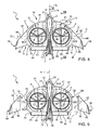
Figure 3 is a perspective view of the convertiplane ofFigures 1 and 2 in a transition mode between the helicopter and the aeroplane mode; -
Figure 4 is a top view of the convertiplane ofFigures 1 to 3 in a first operative configuration; -
Figure 5 is a top view of the convertiplane ofFigures 1 to 3 in a second operative configuration; -
Figure 6 and 7 cross sections of first components ofFigure 4 taken along lines VI-VI and VII-VII respectively ofFigure 6 ; -
Figure 8 is a lateral view of the convertiplane ofFigures 1 to 3 in the second operative configuration; -
Figure 9 is a perspective view of a further component of the convertiplane ofFigures 1 to 4 , with parts removed for clarity; -
Figure 10 is a cross section of the fourth component taken along line X-X ofFigure 9 ; and -
Figures 11 to 17 are perspective view of respective components of the convertiplane ofFigures 1 to 4 , with parts removed for clarity. -
Number 1 inFigures 1 to 3 indicates as a whole a convertiplane, i.e. a hybrid aircraft capable of being selectively operated in an aeroplane mode (Figure 1 ) or in a helicopter mode (Figure 2 ). -
Convertiplane 1 substantially comprises: - a
fuselage 2 elongated along a longitudinal direction A ofconvertiplane 1; - a pair of
semi-wings 3 which project on opposite respective lateral sides offuselage 2; and - a pair of
rotors 4. - In greater detail,
fuselage 2 has a forward end 15 abackward end 16 which are opposite to each other, along direction A and define opposite ends ofconvertiplane 1. -
Fuselage 2 also comprises (Figure 6 ): - a
forward portion 12 housing acockpit 31; and - a
backward portion 13. - Each
rotor 4 substantially comprises: - a
housing 5; - a
shaft 6 supported by housing rotatably about a relative axis B; and - an
ogive 14 rotatably integral withshaft 6 about relative axis B. - Each
rotor 4 also comprises a plurality ofblades 27, three in the embodiment shown, which are articulated relative toshaft 6 through the interposition of ahub 28. - In detail,
rotors 4 rotate about relative axes B in opposite directions. In this way,convertiplane 1 does not need an anti-rotation device. - With reference to
Figure 6 , the transversal section offuselage 2 in a plane parallel to direction A and orthogonal to axis C is shaped asairfoil 35. - More precisely,
airfoil 35 comprises: - a leading edge which is defined by
end 15; - a trailing edge which is defined by
end 16; - a
topside 37 which joinsends - a
bottom side 38 which joinsends topside 37. - Topside and
bottom side - Topside and
bottom side rectilinear chord 39 which connectsedges - In this way,
airfoil 35 generates a lift, whenconvertiplane 1 flies with direction A slightly inclined relative to a horizontal plane, due to the fact that the air current direction is not parallel tochord 39.Convertiplane 1 also comprises: - a V-shaped
tail 7, which upwardly projects fromportion 13 offuselage 2; and - a plurality of landing gears 9 downwardly protruding from the bottom side of
semi-wings 3. - Each
rotor 4 may also tilt together with its respective axis B relative torespective semi-wing 3. In particular,rotor 4 and relative axis B tilt about a respective axis C which is orthogonal to direction A. - More precisely, axes B of
rotors 4 are substantially orthogonal to direction A, whenconvertiplane 1 is operated in the helicopter mode (Figure 2 ). - In this way,
convertiplane 1 is a "so-called" tilt rotor convertiplane. - Axes B of
rotors 4 are substantially parallel to direction A, whenconvertiplane 1 is operated in the aeroplane mode (Figure 1 ). - Advantageously,
convertiplane 1 defines a pair ofopenings 8 within whichrotors 4 may tilt, whenconvertiplane 1 moves between helicopter and aeroplane mode. - In particular, each semi-wing 3 defines a
relative opening 8. - Each
semi-wing 3 substantially comprises (Figures 4 and 5 ): - a
leading edge 10; and - a trailing
edge 11 opposite to edge 10 and interacting with air current afteredge 10, whenconvertiplane 1 is advanced along direction A. - Leading
edges 10 converge, on respective opposite sides, towardsfuselage 2, when proceeding from V-shapedtail 7 to end 15. - More precisely, the distance measured parallel to axis C between edges 10 decreases proceeding from V-shaped
tail 7 to end 15. - Each leading
edge 10 comprises (Figures 4 and 5 ): - a first
curved stretch 41 laterally projecting on a relative side offuselage 2; and - a
rectilinear stretch 42 which defines a prolongation ofstretch 41 on the relative opposite side offuselage 8. - Each trailing
edge 11 comprises: - a
rectilinear stretch 43 extending parallel to axis C and on a relative lateral side of V-shapedtail 7; - a
curved stretch 44; and - a
rectilinear stretch 45 opposite to stretch 44 relative to stretch 43 and inclined relative to axis C. - As a result of the conformation of trailing and leading
edges - Corresponding stretches 42, 45 protrude upwardly from a plane defined by direction A and axis C, so as to form
relative winglets 19 which are arranged on respective opposite sides offuselage 2. - Each
opening 8 is arranged betweenfuselage 2 andrelative winglet 19 parallel to relative axis C and is arranged betweenstretches - Each
opening 8 extends about an axis D and is, in the embodiment shown, circular. - Furthermore, each
opening 8 has anedge 29, circular in the embodiment shown, - When
convertiplane 1 is operated in the aeroplane mode (Figure 1 ), axes B are orthogonal to respective axes D, androtors 4 protrude from opposite, top and bottom, sides ofrelative openings 8. - Axes B are also orthogonal to relative axes C.
- When
convertiplane 1 is operated in the helicopter mode (Figure 2 ), axes B are parallel to respective axes D androtors 4 are axially contained withinrelative openings 8. - In particular, when
convertiplane 1 is operated in the helicopter mode, the thickness ofrotors 4 parallel to axes D is less than or equal to the thickness ofrelative openings 8 parallel to axes D. - Each
semi-wing 3 comprises (Figure 4 and 5 ): - a
body 17 which definesopening 8; and - a pair of
outboard wings 18 which are detachably connected tobody 17 on respective opposite sides offuselage 2. - As a result,
convertiplane 1 may be operated: - in a first configuration in which
wings 18 are connected to and project, on opposite sides offuselage 2, from body 17 (Figure 4 ); and - in a second configuration, in which
wings 18 are removed from body 17 (Figures 5 and8 ). - More precisely,
body 17 comprisesfuselage 2 and V-shapedtail 7 andopenings 8. -
Body 17 is bounded bystretches 41, stretches 43, 44 and by a pair ofwalls 32 which lies on a plane orthogonal to axis C. - The cross section of
body 17 taken a plane orthogonal to axis C comprises a pair ofairfoils 60, 65 (Figure 7 ). -
Airfoil 60 is bounded between leadingedge 10 and aforward portion 47 ofedge 29 along direction A. -
Airfoil 60 comprises a topside 61 and abottom side 62 which join edges 10 andforward portion 47. -
Airfoil 60 extends symmetrically about arectilinear chord 63 which joinsedge 11 andforward portion 47. - Topside and
bottom side - Proceeding from
forward portion 47 ofedge 29 to edge 10, the distance between topside andbottom side chord 63 at first is increasing an then is decreasing. -
Airfoil 65 is bounded between arearward portion 48 ofedge 29 and trailingedge 11 along direction A. -
Airfoil 65 comprises a topside 66 and abottom side 67 which joinrearward portion 48 and trailingedge 11. -
Airfoil 65 extends symmetrically about a rectilinear chord 68 which joinsedge 11 andrearward portion 48. - Topside and
bottom side - Proceeding from
edge 11 torearward portion 48 ofedge 29, the distance between topside andbottom side chord 63 is at first increasing and then decreasing. - Also in this case, airfoils 60, 65 generate a lift, when
convertiplane 1 flies with direction A slightly inclined relative to a horizontal plane, due to the fact that the air current direction is not parallel tochords 63, 68. - Each
wing 18 comprisesrelative winglet 19 and is bounded byrelative stretches - Each
wing 18 is also bounded by awall 33 on the opposite side ofrelative winglet 19. -
Wall 33 of eachwing 18 is detachably connected to arelative wall 32 ofbody 17. - Each
wing 18 is, in particular, backward swept to provide roll stability and reducing wing span for obtaining a given amount of lift. -
Convertiplane 1 also comprises pair ofelevons 40 which are arranged onrespective stretches 45 and on respective sides of V-shapedtail 7. -
Elevons 40 are hinged tobody 17 about an axis H parallel to axis C. In this way,elevons 40 may move upwardly and downwardly relative tobody 17 for controlling the pitch and the roll during horizontal flight. - Due to the fact that
rotors 4 protrude from semi-wings 3, whenconvertiplane 1 is operated as an aircraft, the airflow speed acting onelevons 40 is particularly high, so increasing the effectiveness ofelevons 40. - Each
rotor 4 comprises (Figure 9 ): - an
annular shroud 20 which ductsrelative blades 27; and - a plurality of
spokes 30 which are, on relative opposite edges, interposed betweenrespective shroud 20 andhousing 5. - In this way,
shroud 20 andspokes 30 rotate integrally withblades 27 of eachrotor 4 about relative axis C, whenconvertiplane 1 moves from helicopter and aeroplane mode and vice versa. - On the contrary,
shroud 20 andspokes 30 are fixed relative to axis B of eachrotor 4. - More in detail, each
shroud 20 extends about relative axis B and has a thickness about a relative axis E orthogonal to relative axis B (Figures 9 and 10 ). - Each
shroud 20 comprises (Figure 10 ): - a leading and a trailing
edges - a topside 23 which joins
edges - a
bottom side 24 opposite totopside 23 and which joinsedge - As evident from
Figures 6 and 7 , the cross section ofshroud 20 taken in the plane defined by relative axes E, B is configured as anairfoil 25. - In other words, topside 23 and
bottom side 24 are antisymmetrical relative to achord 26 which joins leading and trailingedges - In detail, both
topside 23 andbottom side 24 are convex. - Furthermore, the thickness of
airfoil 25, i.e. the distance betweentopside 23 andbottom side 24 measured orthogonally tochord 26, at first increases and then decreases, proceeding from leadingedge 21 to trailingedge 22. -
Convertiplane 1 comprises: - a pair of
actuators 52 operatively connected torelative rotors 4 and adapted to tiltrotors 4 about relative axes C; and - a flight control computer 49 (only schematically shown in
Figure 11 ) adapted to controlactuators 52 independently from each other, so thatrotors 4 may tilt about relative axes C independently from each other. - Each
actuator 52 comprises, in turn, - a
fixed part 53; - a
ram 54 which may slide parallel to direction A relative topart 53; and - a
rod 55 having afirst end 56 hinged to ram 54 about an axis parallel to axis C, and end 58 which integrally tilts together withshroud 20 ofrotor 4 about axis C. - Each
actuator 52 also comprises acontrol unit 51 for controlling the movement ofram 54 parallel to direction A. -
Control units 51 are, in turn, controlled byflight control computer 49 on the basis of a plurality of flight and mission parameters. - The movement of
ram 54 relative to fixedpart 53 is caused by an electric motor (not-shown). - Furthermore, each actuator 52 comprises a
bar 59 which extends parallel to relative axis C. -
Bar 59 of each actuator 52 comprises (Figures 11 and12 ): - an
end 90 integral withend 58 ofrod 55; and - an
end 91 opposite to end 90 and fitted toshroud 20. - More precisely,
convertiplane 1 comprises a plurality of connecting elements 92 (only one of which is shown inFigure 12 ) for connectingrelative spokes 30 toshroud 20. - In detail, each connecting
element 92 comprises a pair ofwalls 94 fitted to relative spoke 30, and acentral portion 95 fitted to a peripheral portion ofshroud 20 and coupled withend 91 ofbar 59. - In particular, each
end 91 and correspondingcentral portion 95 are coupled by using a splined fitting. - In detail,
central portions 95 and ends 91 ofbars 59 are partially housed within a cavity defined by shroud 20 (Figure 12 ). - Starting from helicopter mode, each actuator 52 may tilt
relative rotor 4 towardsend 15 or towardsend 16. - In other words, during the transition from helicopter to airplane mode, each actuator 52 may tilt
relative rotor 4 forward or rearwards relative to axis D. - With reference to
Figures 13 to 16 ,convertiplane 1 comprises an electricalpower storage device 70; and two pairs ofelectric machines 71. - Each
electric machine 71 comprises, in turn, astator 72 electrically connected tostorage device 70, and arotor 73 connected toshaft 6 ofrelative rotor 4. - Each
electric machine 71 may be operated as: - an electric motor to directly drive in rotation
relative shaft 6 about relative axes B, by using the electrical power stored instorage device 70; or - as an electrical power generator for re-charging
storage device 70, by causing the rotation ofrotor 4 using wind energy. - In particular,
rotors 73 are directly connected toshafts 6. - In the present description, the expression "directly connected" is used to indicate that no transmission system is interposed between
rotor 73 andshaft 6. - Accordingly, the angular speed about axes B of
shaft 6 andrelative rotors 73 is equal. - In detail, when
electric machines 71 are operated as electric motors, they are fed with electrical current bystorage device 70. - In detail,
stator 72 of eachelectric machine 71 is fitted withinhousing 5 ofrelative rotor 4; androtor 73 of eachelectric machine 71 is rotatably supported by stator 72 (Figure 13 ). -
Stator 72 of eachelectric machine 71 comprises anannular body 120 elongated along relative axes B and defining a plurality of angularly-spacedseats 121. In particular,seats 121 of eachelectric machine 71 extend radially relative to respective axis B. -
Stator 72 also comprises amagnetic core 79 which defines a helical slot 78 (not-shown inFigure 13 , but only inFigure 14 ). -
Core 79 is housed withinbody 120 andslot 78 is annular relative to axis B. -
Rotor 73 of eachelectric machine 71 comprises a pair of annular plates arranged on relative opposite axial sides ofrelative stator 72. -
Electric machines 71 are, in the embodiment shown, axial flux brushless electric machines, i.e. of the type that generates a magnetic flux predominantly extending about axis B. - Each
electric machine 71 also comprises: - a plurality of
coils 75 which are wound oncore 79, housed withinslot 78, and fed, in use, with alternate current bystorage device 70; and - a plurality of
permanent magnets 76 which are angularly integral withrotor 73 and axially interposed between plates ofrotors 73 andbody 120, so as to be driven in rotation about relative axis B by the magnetic field generated bycoils 75. -
Permanent magnets 76 of eachelectric machine 71 are angularly equi-spaced about relative axis B. -
Electric machines 71 of eachrotor 4 are arranged in series in relation toshaft 6. In other words, the overall torque to whichshaft 6 is subjected about axis B equals the sum of torques exerted by eachelectric motor 71. -
Coils 75 are electrically connected tostorage device 70 by using wires. -
Storage device 70 may comprise (Figures 15 and 16 ): - either one or more
electrical battery 81; or - a
hybrid battery 82 and aninternal combustion engine 83 operatively connected with saidhybrid battery 82. - In the embodiment shown in
Figure 15 ,internal combustion engine 83 rechargeshybrid battery 82. In particular,internal combustion engine 83 is a Diesel engine and comprises atank 84. -
Convertiplane 1 also comprises: - a common core which comprises, in turn, semi-wings 3,
fuselage 2,rotors 4 andelectrical machine 71; and - a module comprising
storage device 70, which may be selectively connected to said common core. -
Storage device 70 is, in the embodiment shown, a Li-Ion battery. -
Convertiplane 1 also comprises a motor controller 130 (Figures 15 and 16 ) which receives electrical power fromstorage device 70 and regulates the power input intoelectrical machines 71 to control the motion ofshafts 6 ofrotors 4. - In detail,
motor controller 130 is fed bystorage device 70 with a continuous current, converts this continuous current into alternate current and feedselectrical machines 71 with alternate current. -
Electric machines 71 may also be operated as an electrical generator during a braking phase ofrelative shaft 6. In this condition,electrical machines 71 generate electrical current which is stored withinbattery 81 orbattery 82. In other words,electrical machines 71, when operated as an electrical generator, define braking means for brakingshafts 6 ofrelative rotors 4. - Furthermore,
convertiplane 1 may be arranged in the aeroplane mode, after that the landing has been completed. - In such a condition, the wind current acting on
blades 27 causes the rotation ofshaft 6. - Also in this condition,
electrical machines 71 are operated as electrical generator and generate electrical current which is stored withinstorage device 70. -
Actuators 52 and battery 81 (or 82) are arranged inportion 13 offuselage 2. -
Fuselage 2 may house a payload pallet and/or a sensor package. -
Convertiplane 1 also comprises, for eachrotor 4, three variable-length actuators 100 which are interposed betweenhousing 5 and relative blades 27 (Figure 17 ). - In detail, each blade 27 (only schematically shown in
Figure 17 ) extends along a relative axis G and is connected tohub 28 by a relativeroot connecting element 99. - Each connecting
element 99 comprises a C-shapedappendix 101 which is eccentric relative to respective axis G. - Each
actuator 100 has afirst end 102 connected tohousing 5 and asecond end 103 connected to appendix 101 ofrelative blade 27. -
End 103 of each actuator 100 may also slide relative to end 102. - In this way,
actuators 100 cause the rotation ofrelative blades 27 about relative axis G. - Accordingly, the angle of attack of each
blade 27 is varied. - In particular,
actuators 100 may both vary: - the angle of attack of all
relative blades 27, i.e. the so-called "collective pitch"; - the cyclical variation of the angles of attack of
relative blades 27 during their rotation about axis B, i.e. the so-called "cyclic pitch"; and - varying the pitch angles of all
relative blades 27, to ensure that lift generated by eachblade 27 is the same, so as to avoid the vibration of therotors 4 due to a unbalance of lift. - Each
actuator 100 may also be used for exerting a given force ontorelative blade 27, so as to suppress the vibration of thisblade 27. - In the embodiment shown,
actuators 100 are electro-mechanical. -
Convertiplane 1 could also comprise canards and/or tailplane to enhance longitudinal stability. - The operation of
convertiplane 1 is described starting from a situation in whichconvertiplane 1 is operated in the helicopter mode andwings 18 are connected tobody 17, which is formed byfuselage 2 andsemi-wings 3. - This configuration is typical of the taking off and/or the landing of
convertiplane 1. -
Wings 18 are connected tobody 17 when an increased value of lift is required. - In particular, when
convertiplane 1 is operated in the helicopter mode, axes B are orthogonal to direction A and parallel to axes D. Furthermore,rotors 4 andrelative shrouds 20 are fully contained withinrelative openings 8. In other words, the thickness ofrotors 4 and shrouds 20 is contained within the size ofrelative openings 8 parallel to corresponding axes D. -
Rotors 4 rotate about relative axes C in opposite direction relative to each other, so that the torques exerted byrotors 4 onconvertiplane 1 are balanced. - In detail,
shaft 6 of eachrotor 4 is driven in rotation about relative axis B by relative pair ofelectric machines 71 which are operated, in this case, as an electric motor. - Very briefly, coils 75 are fed with alternate current by
storage device 70 and generate a variable magnetic flux onpermanent magnets 76. - As a result,
permanent magnets 76 and, therefore,rotor 73 andshafts 6 are driven in rotation about relative axis B. -
Actuators 100 are used for both: - varying the angle of attack of all
relative blades 27, thus varying the so-called "collective pitch"; and/or - varying the cyclical variation of the angles of attack of
relative blades 27 during their rotation about axis B, thus varying the so-called "cyclic pitch". - When
convertiplane 1 is operated in the helicopter mode, the yawing is controlled by tilting onerotor 4 towardsend 15 offuselage 2 andother rotor 4 towardsend 16 offuselage 2. - In this way,
rotors 4 generate respective forces parallel to direction A which are equal and opposite to each other. As a result,convertiplane 1 may yaw. - In detail,
flight control system 49control actuators 52 which tiltrelative rotors 4 about relative axes C and independently of each other. - Each
control unit 51 controls the sliding ofram 54 parallel to direction A. - The translation of
rams 54 causes the rotation ofrods 55, and, therefore ofrelative rotors 4 and shrouds 20 about relative axes C. - When it is necessary to operate
convertiplane 1 in the aeroplane mode,actuators 52tilt rotors 4 andrelative shrouds 20 about relative axes C and towardsend 15. - When
convertiplane 1 is operated in the aeroplane mode,rotors 4 and shrouds 20 protrude in part aboverelative semi-wings 3 and in part belowsemi-wings 3. - In this way, the airflow generated by
rotors 4 impinges both the portion ofsemi-wings 3 arranged belowrotors 4 andelevons 40. - Furthermore,
convertiplane 1 flies, when operated in the aeroplane mode, with direction A slightly inclined relative to a horizontal plane, so that air current defines a not null angle withchords respective airfoils - The majority of the lift is provided by
wings 18. The remaining part of the lift is provided byfuselage 2 and shrouds 20 which ductrelative rotors 4. -
Winglets 19 increase the overall aerodynamic efficiency ofconvertiplane 1. - During horizontal flight, the roll and the pitch is controlled by
rotating elevons 40 about axis H. In detail,elevons 40 may be controlled independently from each other. - V-shaped
tail 7 ensures longitudinal stability in the horizontal flight, thanks to its not-shown customary movable vertical surfaces. -
Rotors 4 can be braked by operatingelectrical machines 71 as alternate current electrical generator, instead of electric motor. - In this way, the deceleration of
rotors 4 and, therefore, ofshafts 6 causes the storage of electrical energy within batteries 81 (or 82). - In case that the mission profile mostly requires
convertiplane 1 be operated in the helicopter mode,wings 18 are detached frombody 17, without changing the previously described operation ofconvertiplane 1. - When
convertiplane 1 is operated in the aeroplane mode, it can be moved rearwards, by tilting bothrotors 4 towardsend 16 and with axes B substantially parallel to direction A. - When
convertiplane 1 is on ground andstorage device 70 needs to be re-charged,rotors 4 are tilted about relative axes C in a direction facing the wind current. - At this stage, the wind current drives in
rotation shafts 6 ofrotors 4, which in turn, cause the rotation ofrotors 73 ofelectrical machines 71 relative to stators 72. - In other words,
electrical machines 71 are operated as electrical power generators which re-chargestorage device 70. - The advantages of
convertiplane 1 according to the present invention will be clear from the foregoing description. - In particular,
convertiplane 1 defines a pair of throughopenings 8 withinrotors 4 tilt. - In this way, when
convertiplane 1 is operated in the helicopter mode, the downwash fromrotors 4 substantially is not directed ontosemi-wings 3. - As a result, semi-wings 3 substantially do not suffer from wind shielding effect during hovering, when
convertiplane 1 is operated in the helicopter mode. - Furthermore,
rotors 4 tilt inopenings 8 which are defined bysemi-wings 3. - As a result, semi-wings 3 surround
relative rotor 4, instead of protruding bearing rotors as in the prior art solution. - In this way, semi-wings 3 may be configured to generate a considerable amount of lift, when compared with the convertiplane solution described in the introductory part of the present description.
- Furthermore, shrouds 20 have an
airfoil 25, i.e. have a transversal section which generates a lift when impinged by the airflow, when theconvertiplane 1 is operated in the aeroplane mode and axes B are inclined relative to direction A. - Finally,
fuselage 2 also defines anairfoil 35 and is smoothly joined tobody 17 which, in turn, definesairfoils - In this way, also
fuselage 2 andbody 17 contribute to the lift generation, whenconvertiplane 1 is operated in the aeroplane mode and the direction A is slightly inclined relative to a horizontal plane. As a matter of fact, in these conditions, the airflow is inclined relative tochords respective airfoils - Accordingly, the lift generated by
convertiplane 1 is highly increased with respect both in aircraft and helicopter mode, when compared to convertiplane solutions described in the introductory part of the present description. -
Convertiplane 1 also comprisesshrouds 20 withduct rotors 4 and tilt together withrotors 4 about corresponding axes C. - In this way, the efficiency of
rotor 4 is particularly high, because for the same diameter, the thrust of a ducted propeller, asrotor 4, is larger than the thrust of a free propeller. - Furthermore, shrouds 20 are effective in reducing the noise generated by
relative rotors 4. -
Convertiplane 1 also comprises a pair ofelevons 40 which are arranged at trailingedge 11 ofsemi-wings 3. - In this way, the airflow generated by
rotors 4 is directed againstelevons 40, whenconvertiplane 1 is operated in the aeroplane mode. - Accordingly, the airflow speed on
elevons 40 is increased, thus increasing the effectiveness ofelevons 40. -
Wings 18 are detachably connected tobody 17. In this way, the flight configuration ofconvertiplane 1 may be optimized, depending on the mission to be completed. - In detail, when the mission profile mainly comprises forward flight portions, i.e. when
convertiplane 1 is mostly operated in the aeroplane mode at high cruise speed rather in the helicopter mode,wings 18 are coupled tobody 17. In this way, the aerodynamic efficiency is highly increased. - On the contrary, when the mission profile requires that
convertiplane 1 mostly be operated in the helicopter mode and in the aeroplane mode at low speed,wings 18 are detached frombody 17. In this way, the overall weight ofconvertiplane 1 is lowered, since a reduced amount of lift is required by the mission profile. - Semi-wings 3 are shaped as delta wings. This shape brings, when
convertiplane 1 is operated as an aeroplane, the centre of gravity ofconvertiplane 1 close to axes B, D. In this way, the stability ofconvertiplane 1 is highly enhanced in aeroplane and helicopter mode and during the transition between these two modes. -
Wings 18 are also backward swept. In this way, the span ofwings 18 is reduced, the lift generated bywings 18 being the same. - Furthermore, the reduction of the span of
wings 18 is also useful for reducing the visual signature ofconvertiplane 1. -
Fuselage 2 may easily housecockpit 31 and/or a payload pallet and/or a sensor package. - In this way,
convertiplane 1 has a modular design, with a common core, which can be optimized to different roles, for examples surveillance, intelligence, firefighting, disaster relief. - Finally, axes D are closer to the centre of gravity of convertiplane 1 (arranged on fuselage 2) than the tips of
semi-wings 3. In this way, the bending moments generated by the weight ofrotors 4 are dramatically reduced when compared with the bending moments generated by the rotors described in the introductory part of the present description. - Clearly, changes may be made to
convertiplane 1 as described and illustrated herein without, however, departing from the scope of the present invention as defined in the accompanying Claims. - In particular, each
rotor 4 could be replaced by a pair ofcounter-rotating rotors 4. In this case, the gyroscopic inertia would be substantially null and the tilting of each pair ofrotors 4 would require a reduced torque about axes C.
characterized by comprising at least two through openings within which the rotors may tilt about second axes, when said convertiplane moves between said helicopter and aeroplane mode.
Claims (14)
- A convertiplane (1) comprising:- a pair of semi-wings (3);- at least two rotors (4) which may rotate about a first axes (B) and tilt about relative second axes (C) together with said first axes (B) with respect to said semi-wings (3) between a helicopter mode and an aeroplane mode;said first axes (B) being, in use, transversal to a longitudinal direction (A) of said convertiplane (1) in said helicopter mode, and being, in use, substantially parallel to said longitudinal direction (A) in said aeroplane mode;
characterized by comprising at least two through openings (8) within which said rotors (4) may tilt, when said convertiplane (1) moves, in use, between said helicopter and said aeroplane mode. - The convertiplane of claim 1, characterized in that said rotors (4) are fully contained within said openings (8), when said convertiplane (1) is operated in said helicopter mode.
- The convertiplane of claim 1 or 2, characterized by comprising at least two shrouds (20) which duct relative rotors (4) and may tilt together with said relative rotors (4) with respect to said semi-wings (3).
- The convertiplane of claim 3, characterized in that each said shroud (20) is, in a cross section taken in a plane parallel to first axis (B), shaped as a first airfoil (25);
said first airfoil (25) comprising:- a first leading edge (21);- a first trailing edge (22);- a chord (26) connecting said first leading and trailing edges (21, 22);said first airfoil (25) being antisymmetrical relative to said chord (26). - The convertiplane of any one of the foregoing claims, characterized in that each said rotor (4) projects on the top of said semi-wing (3), when said helicopter (1) is operated in said aeroplane mode.
- The convertiplane of any one of the foregoing claims, characterized by comprising a fuselage (2) from which said semi-wings (3) project on opposite relative sides; said fuselage (2) defining a forward end (15) of said convertiplane (1), proceeding according to an advancing direction thereof;
each said semi-wing (3) having a respective second leading edge (10) which converges towards said fuselage (2) and extends at increasing distances from each other, starting from said forward end (15) and proceeding along said advancing direction (A);
each said semi-wing (3) having a substantially rectilinear second trailing edge (11) which is opposite to relative second leading edge (10), proceeding along said first direction (A);
each said opening (8) being arranged between respective portions (41, 45) of said second leading edge (10) and second said trailing edge (11) of a relative said semi-wing (3), proceeding along said direction (A). - The convertiplane according to claim 6, characterized in that the cross section of said semi-wing (3) taken in a plane orthogonal to said second axis (C) comprises:- a second airfoil (60); and- a third airfoil (65) arranged on the opposite side of said opening (8) relative to said second airfoil (60);said second airfoil (60) being bounded by said second leading edge (10) and by a third trailing edge (29; 47);
said third airfoil (65) being bounded a third leading edge (29; 48) and by said second trailing edge (11);
said third leading and trailing edges (29; 47, 48) bounding said opening (8) on opposite sides relative to said direction (A). - The convertiplane of claim 6 or 7, characterized by comprising a pair of elevons (40) movable relative to respective semi-wings (3) and defined by said second trailing edge (11), proceeding along said direction (A), so that, when said convertiplane (1) is operated in said helicopter mode, said rotors (4) generate an airflow against said elevons (40).
- The convertiplane of any one of claim 6 to 8, characterized in that said fuselage (2) is smoothly joined to said semi-wings (3) and is configured, in a cross section in a plane orthogonal to said second axis (C), as a fourth airfoil (35).
- The convertiplane of any one of the foregoing claims characterized in that each semi-wing (3) comprises:- a main body (17); and- a pair of wings (18) detachably connected to said main body (17), so that said convertiplane (1) may be selectively operated in:- a first configuration in which said wings (18) are connected to said main body (17); and- a second configuration in which said wings (18) are released from said main body (17).
- The convertiplane of claim 10, characterized in that said wings (18) are backward swept.
- The convertiplane of any one of claims 9 to 11, characterized by comprising:- a common core comprising said semi-wings (3), said openings (8) and said rotors (4); and- a module which can be selectively housed within said fuselage (2);said module comprising at least one of a cockpit (31), a payload pallet and/or a sensor assembly.
- The convertiplane according to any one of previous claim, characterized in that said rotor (4) comprises:- a shaft (6);- a plurality of blades (27) rotatable integrally with said shaft (6) about said first axis (B) and articulated with respect to said shaft (6) about respective third axes (G); and- a plurality of actuators (100) connected to relative blades (27) for causing the rotation of said blades (27) about relative third axes (G) and/or for exerting onto respective blades (27) a force which is directed to suppress the vibration of said blades (27).
- The convertiplane of claim 13, characterized in that said actuators (100) are electro-mechanical actuators (100).
Priority Applications (8)
| Application Number | Priority Date | Filing Date | Title |
|---|---|---|---|
| EP11425208.3A EP2551190B1 (en) | 2011-07-29 | 2011-07-29 | Convertiplane |
| PL11425208T PL2551190T3 (en) | 2011-07-29 | 2011-07-29 | Convertiplane |
| PT114252083T PT2551190E (en) | 2011-07-29 | 2011-07-29 | Convertiplane |
| JP2012167222A JP2013032147A (en) | 2011-07-29 | 2012-07-27 | Convertiplane |
| US13/560,142 US8991741B2 (en) | 2011-07-29 | 2012-07-27 | Convertiplane |
| RU2012132327/11A RU2012132327A (en) | 2011-07-29 | 2012-07-27 | Convert |
| CN201210269560.8A CN102897317B (en) | 2011-07-29 | 2012-07-30 | Convertiplane |
| KR1020120083462A KR101958328B1 (en) | 2011-07-29 | 2012-07-30 | Convertiplane |
Applications Claiming Priority (1)
| Application Number | Priority Date | Filing Date | Title |
|---|---|---|---|
| EP11425208.3A EP2551190B1 (en) | 2011-07-29 | 2011-07-29 | Convertiplane |
Publications (2)
| Publication Number | Publication Date |
|---|---|
| EP2551190A1 true EP2551190A1 (en) | 2013-01-30 |
| EP2551190B1 EP2551190B1 (en) | 2013-11-20 |
Family
ID=45063079
Family Applications (1)
| Application Number | Title | Priority Date | Filing Date |
|---|---|---|---|
| EP11425208.3A Active EP2551190B1 (en) | 2011-07-29 | 2011-07-29 | Convertiplane |
Country Status (8)
| Country | Link |
|---|---|
| US (1) | US8991741B2 (en) |
| EP (1) | EP2551190B1 (en) |
| JP (1) | JP2013032147A (en) |
| KR (1) | KR101958328B1 (en) |
| CN (1) | CN102897317B (en) |
| PL (1) | PL2551190T3 (en) |
| PT (1) | PT2551190E (en) |
| RU (1) | RU2012132327A (en) |
Cited By (24)
| Publication number | Priority date | Publication date | Assignee | Title |
|---|---|---|---|---|
| NL2011128C2 (en) * | 2013-07-09 | 2015-01-12 | Eco Logical Entpr B V | ROTATING DEVICE, FOR EXAMPLE A AIR MOUNT, SUCH AS A FAN, A PROPELLER OR LIFT SCREW, A WATER TURBINE OR A WIND TURBINE. |
| ITPI20130073A1 (en) * | 2013-08-08 | 2015-02-09 | Claudio Bottoni | AEROMOBILE BOXWING |
| CN104648656A (en) * | 2015-02-12 | 2015-05-27 | 厦门大学 | Vertical take-off and landing unmanned plane lift augmentation control device and vertical take-off and landing unmanned plane lift augmentation control method |
| WO2015124556A1 (en) * | 2014-02-18 | 2015-08-27 | Iat 21 Innovative Aeronautics Technologies Gmbh | Aircraft |
| EP2985220A1 (en) * | 2014-08-11 | 2016-02-17 | Dusan Milivoi Stan | Apparatus and method for providing control and augmenting thrust at reduced speed and ensuring reduced drag at increased speed |
| US9583132B2 (en) | 2013-07-24 | 2017-02-28 | Eco-Logical Enterprises B.V. | Arrangement for rotatably driving a round disk |
| EP3184425A1 (en) | 2015-12-21 | 2017-06-28 | AIRBUS HELICOPTERS DEUTSCHLAND GmbH | Multirotor aircraft |
| US9873508B2 (en) | 2015-12-11 | 2018-01-23 | Coriolis Games Corporation | Hybrid multicopter and fixed wing aerial vehicle |
| EP3354559A1 (en) | 2017-01-26 | 2018-08-01 | AIRBUS HELICOPTERS DEUTSCHLAND GmbH | A thrust producing unit with at least two rotor assemblies and a shrouding |
| EP3354566A1 (en) | 2017-01-26 | 2018-08-01 | AIRBUS HELICOPTERS DEUTSCHLAND GmbH | A thrust producing unit with at least two rotor assemblies and a shrouding |
| EP3366586A1 (en) | 2017-02-27 | 2018-08-29 | AIRBUS HELICOPTERS DEUTSCHLAND GmbH | A thrust producing unit with at least two rotor assemblies and a shrouding |
| EP3366582A1 (en) | 2017-02-28 | 2018-08-29 | AIRBUS HELICOPTERS DEUTSCHLAND GmbH | A multirotor aircraft with an airframe and a thrust producing units arrangement |
| CN109279001A (en) * | 2017-07-21 | 2019-01-29 | 通用电气公司 | The aircraft of vertical takeoff and landing |
| EP3470332A1 (en) | 2017-10-13 | 2019-04-17 | AIRBUS HELICOPTERS DEUTSCHLAND GmbH | A multirotor aircraft with an airframe and at least one wing |
| US10283256B2 (en) | 2013-07-09 | 2019-05-07 | Eco-Logical Enterprises B.V. | Compact electrical device and electrodynamic loudspeaker, electric motor, stirring device and adjustable clutch based thereon |
| RU2700103C1 (en) * | 2018-06-26 | 2019-09-12 | Виталий Владиславович Фирсов | Aircraft power plant on two-hover suspension |
| EP3581490A1 (en) | 2018-06-13 | 2019-12-18 | AIRBUS HELICOPTERS DEUTSCHLAND GmbH | A multirotor aircraft with a thrust producing unit that comprises an aerodynamically optimized shrouding |
| CH715122A1 (en) * | 2018-06-25 | 2019-12-30 | kopter group ag | Rotary wing with an electric drive for driving a main and / or tail rotor of the rotary wing. |
| DE102018116161A1 (en) | 2018-07-04 | 2020-01-09 | Dr. Ing. H.C. F. Porsche Aktiengesellschaft | aircraft |
| EP3656669A1 (en) | 2018-11-26 | 2020-05-27 | AIRBUS HELICOPTERS DEUTSCHLAND GmbH | A vertical take-off and landing multirotor aircraft with at least eight thrust producing units |
| EP3702277A1 (en) | 2019-02-27 | 2020-09-02 | AIRBUS HELICOPTERS DEUTSCHLAND GmbH | A multirotor aircraft that is adapted for vertical take-off and landing (vtol) |
| EP3702276A1 (en) | 2019-02-27 | 2020-09-02 | AIRBUS HELICOPTERS DEUTSCHLAND GmbH | A multirotor joined-wing aircraft with vtol capabilities |
| RU2786031C2 (en) * | 2018-06-25 | 2022-12-16 | коптер груп аг | Aircraft with main rotor with electric drive for actuation of main rotor and/or tail rotor of this aircraft with main rotor |
| US11603193B2 (en) * | 2018-07-16 | 2023-03-14 | Donghyun Kim | Aircraft convertible between fixed-wing and hovering orientations |
Families Citing this family (45)
| Publication number | Priority date | Publication date | Assignee | Title |
|---|---|---|---|---|
| US9493235B2 (en) * | 2002-10-01 | 2016-11-15 | Dylan T X Zhou | Amphibious vertical takeoff and landing unmanned device |
| US9776715B2 (en) * | 2002-10-01 | 2017-10-03 | Andrew H B Zhou | Amphibious vertical takeoff and landing unmanned device |
| EP2551193B1 (en) * | 2011-07-29 | 2016-04-13 | AGUSTAWESTLAND S.p.A. | Convertiplane |
| US20130134254A1 (en) * | 2011-11-29 | 2013-05-30 | Jason Moore | UAV Fire-fighting System |
| DE102012018499A1 (en) * | 2012-09-18 | 2014-03-20 | Innovative Dragon Ltd. | Drive system for and resulting overall design of aircraft |
| AU2013327362B2 (en) | 2012-10-05 | 2017-04-20 | Marcus LENG | Electrically powered aerial vehicles and flight control methods |
| KR101287624B1 (en) * | 2013-02-25 | 2013-07-23 | 주식회사 네스앤텍 | Unmanned aerial vehicle for easily landing |
| US20150367932A1 (en) * | 2013-10-05 | 2015-12-24 | Dillon Mehul Patel | Delta M-Wing Unmanned Aerial Vehicle |
| CN103587682A (en) * | 2013-11-11 | 2014-02-19 | 中国南方航空工业(集团)有限公司 | Air vehicle |
| WO2016018486A2 (en) * | 2014-05-07 | 2016-02-04 | XTI Aircraft Company | Vtol aircraft |
| JP6425466B2 (en) * | 2014-09-01 | 2018-11-21 | 国立大学法人 東京大学 | Flight equipment |
| US10640204B2 (en) * | 2015-03-03 | 2020-05-05 | Amazon Technologies, Inc. | Unmanned aerial vehicle with a tri-wing configuration |
| CN104648653B (en) * | 2015-03-10 | 2016-08-24 | 朱幕松 | Four rotors go straight up to fly electronic unmanned plane soon |
| DE102015017425B3 (en) | 2015-04-23 | 2023-03-16 | Lilium GmbH | Aerofoil for an aircraft and aircraft |
| DE102015207445B4 (en) | 2015-04-23 | 2023-08-17 | Lilium GmbH | Aerofoil for an aircraft and aircraft |
| CN105151292B (en) * | 2015-05-25 | 2017-05-17 | 郝思阳 | Distributive vectored thrust system |
| CN107614379A (en) * | 2015-05-25 | 2018-01-19 | 多特瑞尔技术有限公司 | Shield for aircraft |
| US11034443B2 (en) | 2015-06-12 | 2021-06-15 | Sunlight Aerospace Inc. | Modular aircraft assembly for airborne and ground transport |
| US9714090B2 (en) * | 2015-06-12 | 2017-07-25 | Sunlight Photonics Inc. | Aircraft for vertical take-off and landing |
| US9541924B2 (en) | 2015-06-12 | 2017-01-10 | Sunlight Photonics Inc. | Methods and apparatus for distributed airborne transportation system |
| CN105059537B (en) * | 2015-08-11 | 2017-05-17 | 上海电机学院 | UAV (unmanned aerial vehicle) |
| CN106494608A (en) * | 2015-09-06 | 2017-03-15 | 陈康 | Many shrouded propeller variable geometry Electric aircrafts |
| CN105620749A (en) * | 2016-03-03 | 2016-06-01 | 三翼航空科技南通有限公司 | Rollin wing variable pitch mechanism |
| CN105857600A (en) * | 2016-03-18 | 2016-08-17 | 西安交通大学 | High-mobility multifunctional unmanned aerial vehicle with separated power and control |
| CN105923153A (en) * | 2016-05-21 | 2016-09-07 | 辽宁辽飞航空科技有限公司 | Fixed-wing aircraft capable of vertically taking off and landing |
| CN107585294A (en) * | 2016-07-08 | 2018-01-16 | 袁洪跃 | A kind of interior rotor craft structure |
| US10106253B2 (en) * | 2016-08-31 | 2018-10-23 | Bell Helicopter Textron Inc. | Tilting ducted fan aircraft generating a pitch control moment |
| US10279900B2 (en) | 2016-08-10 | 2019-05-07 | Bell Helicopter Textron Inc. | Rotorcraft variable thrust cross-flow fan systems |
| CN106184756B (en) * | 2016-08-18 | 2019-06-28 | 国网浙江省电力公司衢州供电公司 | A kind of detachable unmanned plane of bionical electric ray |
| EP3290334B1 (en) * | 2016-08-31 | 2021-08-11 | Sunlight Aerospace Inc. | Aircraft for vertical take-off and landing |
| US10293931B2 (en) | 2016-08-31 | 2019-05-21 | Bell Helicopter Textron Inc. | Aircraft generating a triaxial dynamic thrust matrix |
| US10384776B2 (en) | 2017-02-22 | 2019-08-20 | Bell Helicopter Textron Inc. | Tiltrotor aircraft having vertical lift and hover augmentation |
| JP2018176782A (en) * | 2017-04-03 | 2018-11-15 | 株式会社Soken | Flight device |
| US10814967B2 (en) | 2017-08-28 | 2020-10-27 | Textron Innovations Inc. | Cargo transportation system having perimeter propulsion |
| JP6879866B2 (en) * | 2017-08-28 | 2021-06-02 | 本田技研工業株式会社 | Vertical takeoff and landing aircraft |
| EP3587259B1 (en) * | 2018-06-28 | 2022-08-10 | Leonardo S.p.A. | Tail sitter and related control method |
| CN109353496B (en) * | 2018-07-04 | 2022-05-31 | 哈尔滨工业大学(威海) | Unfolding type delta wing flying device |
| CN108791878A (en) * | 2018-07-12 | 2018-11-13 | 首航国翼(武汉)科技有限公司 | A kind of Modularized unmanned machine |
| US10913542B2 (en) * | 2018-07-27 | 2021-02-09 | Textron Innovations Inc. | Conversion actuator and downstop striker fitting for a tiltrotor aircraft |
| US10994839B2 (en) | 2018-07-31 | 2021-05-04 | Textron Innovations Inc. | System and method for rotating a rotor of a tiltrotor aircraft |
| DE102019001240B4 (en) * | 2019-02-20 | 2021-02-04 | Gabor Siegfried Andrä | Electrically powered, vertical take-off and landing aircraft for transporting people and loads with a modular, fail-safe drive concept and maximum lift surface |
| CN113104195B (en) * | 2021-05-19 | 2022-03-11 | 涵涡智航科技(玉溪)有限公司 | Double-duct composite wing aircraft |
| IT202100018170A1 (en) * | 2021-07-09 | 2023-01-09 | Gen Electric | HYBRID ELECTRIC AIRPLANE WITH GYRO STABILIZATION CONTROL |
| CN114620226B (en) * | 2022-01-28 | 2022-11-15 | 南昌航空大学 | Folding wing flying wing aircraft with hidden rotor wing |
| CN116674747B (en) * | 2023-08-03 | 2023-10-20 | 西南石油大学 | Flexible flapping wing and ducted propeller hybrid-driven simulated baton floating aircraft |
Citations (10)
| Publication number | Priority date | Publication date | Assignee | Title |
|---|---|---|---|---|
| BE459370A (en) * | ||||
| US2375423A (en) * | 1942-02-02 | 1945-05-08 | Malcolm Ltd R | Aircraft |
| US3335977A (en) * | 1965-06-16 | 1967-08-15 | Ludwig F Meditz | Convertiplane |
| US5383627A (en) * | 1992-08-20 | 1995-01-24 | Bundo; Mutsuro | Omnidirectional propelling type airship |
| EP1057724A2 (en) | 1999-06-02 | 2000-12-06 | Agusta S.p.A. | Tilt-rotor aircraft |
| US6220545B1 (en) | 1999-08-06 | 2001-04-24 | Bell Helicopter Textron Inc. | Method and apparatus for sensing preload in a tilt rotor downstop |
| US6434768B2 (en) | 1999-09-30 | 2002-08-20 | Mattel, Inc. | Collapsible play yard |
| US20090256026A1 (en) | 2008-04-11 | 2009-10-15 | Karem Aircraft, Inc. | Tilt Actuation for a Rotorcraft |
| US20110003135A1 (en) | 2006-09-04 | 2011-01-06 | Nitto Denko Corporation | Ultraviolet-curable pressure-sensitive adhesive composition, ultraviolet-curable pressure-sensitive adhesive sheet and process for producing the same |
| US20110046821A1 (en) * | 2009-07-22 | 2011-02-24 | Grabowsky John F | Reconfigurable aircraft |
Family Cites Families (14)
| Publication number | Priority date | Publication date | Assignee | Title |
|---|---|---|---|---|
| US3284027A (en) * | 1964-01-09 | 1966-11-08 | Nord Aviation | Vtol aircraft having freely pivoted propulsion means |
| US5320305A (en) * | 1992-07-22 | 1994-06-14 | Lockheed Corporation | Propulsion system for an aircraft providing V/STOL capability |
| US5839691A (en) * | 1996-05-22 | 1998-11-24 | Lariviere; Jean Soulez | Vertical takeoff and landing aircraft |
| US6343768B1 (en) * | 2000-05-16 | 2002-02-05 | Patrick John Muldoon | Vertical/short take-off and landing aircraft |
| CN1313225A (en) * | 2000-12-28 | 2001-09-19 | 唐廷安 | Aircraft with slant rotor |
| JP2003137192A (en) * | 2001-10-31 | 2003-05-14 | Mitsubishi Heavy Ind Ltd | Vertical taking-off/landing craft |
| US6808140B2 (en) * | 2002-02-08 | 2004-10-26 | Moller Paul S | Vertical take-off and landing vehicles |
| WO2006069291A2 (en) * | 2004-12-22 | 2006-06-29 | Aurora Flight Sciences Corporation | System and method for utilizing stored electrical energy for vtol aircraft thrust enhancement and attitude control |
| CN2789131Y (en) * | 2005-05-16 | 2006-06-21 | 沙庆军 | Multifunction aerobat |
| ITBR20060004A1 (en) * | 2006-03-24 | 2007-09-25 | Maio Gaetano Di | COVERTIBLE AIRPLANE |
| US20090114771A1 (en) * | 2007-11-05 | 2009-05-07 | Qian Mu | Split Return Wing |
| FR2927880B1 (en) * | 2008-02-27 | 2010-08-20 | Eurocopter France | HELICOPTER COMPRISING A PLURALITY OF SUSTAINING ELEMENTS WITH A COMPONENT FOR CONTROLLING THE IMPACT OF ITS BLADES |
| WO2011066400A1 (en) * | 2009-11-25 | 2011-06-03 | Aerovironment, Inc. | Automatic configuration control of a device |
| US20110147533A1 (en) * | 2009-12-21 | 2011-06-23 | Honeywell International Inc. | Morphing ducted fan for vertical take-off and landing vehicle |
-
2011
- 2011-07-29 EP EP11425208.3A patent/EP2551190B1/en active Active
- 2011-07-29 PT PT114252083T patent/PT2551190E/en unknown
- 2011-07-29 PL PL11425208T patent/PL2551190T3/en unknown
-
2012
- 2012-07-27 JP JP2012167222A patent/JP2013032147A/en not_active Ceased
- 2012-07-27 RU RU2012132327/11A patent/RU2012132327A/en not_active Application Discontinuation
- 2012-07-27 US US13/560,142 patent/US8991741B2/en active Active
- 2012-07-30 KR KR1020120083462A patent/KR101958328B1/en active IP Right Grant
- 2012-07-30 CN CN201210269560.8A patent/CN102897317B/en active Active
Patent Citations (10)
| Publication number | Priority date | Publication date | Assignee | Title |
|---|---|---|---|---|
| BE459370A (en) * | ||||
| US2375423A (en) * | 1942-02-02 | 1945-05-08 | Malcolm Ltd R | Aircraft |
| US3335977A (en) * | 1965-06-16 | 1967-08-15 | Ludwig F Meditz | Convertiplane |
| US5383627A (en) * | 1992-08-20 | 1995-01-24 | Bundo; Mutsuro | Omnidirectional propelling type airship |
| EP1057724A2 (en) | 1999-06-02 | 2000-12-06 | Agusta S.p.A. | Tilt-rotor aircraft |
| US6220545B1 (en) | 1999-08-06 | 2001-04-24 | Bell Helicopter Textron Inc. | Method and apparatus for sensing preload in a tilt rotor downstop |
| US6434768B2 (en) | 1999-09-30 | 2002-08-20 | Mattel, Inc. | Collapsible play yard |
| US20110003135A1 (en) | 2006-09-04 | 2011-01-06 | Nitto Denko Corporation | Ultraviolet-curable pressure-sensitive adhesive composition, ultraviolet-curable pressure-sensitive adhesive sheet and process for producing the same |
| US20090256026A1 (en) | 2008-04-11 | 2009-10-15 | Karem Aircraft, Inc. | Tilt Actuation for a Rotorcraft |
| US20110046821A1 (en) * | 2009-07-22 | 2011-02-24 | Grabowsky John F | Reconfigurable aircraft |
Cited By (45)
| Publication number | Priority date | Publication date | Assignee | Title |
|---|---|---|---|---|
| NL2011128C2 (en) * | 2013-07-09 | 2015-01-12 | Eco Logical Entpr B V | ROTATING DEVICE, FOR EXAMPLE A AIR MOUNT, SUCH AS A FAN, A PROPELLER OR LIFT SCREW, A WATER TURBINE OR A WIND TURBINE. |
| WO2015005776A1 (en) * | 2013-07-09 | 2015-01-15 | Eco-Logical Enterprises B.V. | Rotary device, for instance an air mover such as a fan, a propeller or a lifting rotor, a water turbine or a wind turbine |
| US10283256B2 (en) | 2013-07-09 | 2019-05-07 | Eco-Logical Enterprises B.V. | Compact electrical device and electrodynamic loudspeaker, electric motor, stirring device and adjustable clutch based thereon |
| US10479489B2 (en) | 2013-07-09 | 2019-11-19 | Eco-Logical Enterprises B.V. | Rotary device, for instance an air mover such as a fan, a propeller or a lifting rotor, a water turbine or a wind turbine |
| US9583132B2 (en) | 2013-07-24 | 2017-02-28 | Eco-Logical Enterprises B.V. | Arrangement for rotatably driving a round disk |
| ITPI20130073A1 (en) * | 2013-08-08 | 2015-02-09 | Claudio Bottoni | AEROMOBILE BOXWING |
| WO2015019255A1 (en) * | 2013-08-08 | 2015-02-12 | Bottoni Claudio | Boxwing aircraft |
| WO2015124556A1 (en) * | 2014-02-18 | 2015-08-27 | Iat 21 Innovative Aeronautics Technologies Gmbh | Aircraft |
| EP2985220A1 (en) * | 2014-08-11 | 2016-02-17 | Dusan Milivoi Stan | Apparatus and method for providing control and augmenting thrust at reduced speed and ensuring reduced drag at increased speed |
| CN104648656A (en) * | 2015-02-12 | 2015-05-27 | 厦门大学 | Vertical take-off and landing unmanned plane lift augmentation control device and vertical take-off and landing unmanned plane lift augmentation control method |
| CN104648656B (en) * | 2015-02-12 | 2017-02-01 | 厦门大学 | Vertical take-off and landing unmanned plane lift augmentation control device and vertical take-off and landing unmanned plane lift augmentation control method |
| US9873508B2 (en) | 2015-12-11 | 2018-01-23 | Coriolis Games Corporation | Hybrid multicopter and fixed wing aerial vehicle |
| US10035591B2 (en) | 2015-12-11 | 2018-07-31 | Coriolis Games Corporation | Hybrid multicopter and fixed wing aerial vehicle |
| US10239611B2 (en) | 2015-12-11 | 2019-03-26 | Coriolis Games Corporation | Hybrid multicopter and fixed wing aerial vehicle |
| US11052998B2 (en) | 2015-12-21 | 2021-07-06 | Airbus Helicopters Deutschland GmbH | Multirotor electric aircraft with redundant security architecture |
| EP3184425A1 (en) | 2015-12-21 | 2017-06-28 | AIRBUS HELICOPTERS DEUTSCHLAND GmbH | Multirotor aircraft |
| EP3354559A1 (en) | 2017-01-26 | 2018-08-01 | AIRBUS HELICOPTERS DEUTSCHLAND GmbH | A thrust producing unit with at least two rotor assemblies and a shrouding |
| EP3354566A1 (en) | 2017-01-26 | 2018-08-01 | AIRBUS HELICOPTERS DEUTSCHLAND GmbH | A thrust producing unit with at least two rotor assemblies and a shrouding |
| US10737766B2 (en) | 2017-01-26 | 2020-08-11 | Airbus Helicopters Deutschland GmbH | Thrust producing unit with at least two rotor assemblies and a shrouding |
| US11220325B2 (en) | 2017-02-27 | 2022-01-11 | Airbus Helicopters Deutschland GmbH | Thrust producing unit with at least two rotor assemblies and a shrouding |
| EP3366586A1 (en) | 2017-02-27 | 2018-08-29 | AIRBUS HELICOPTERS DEUTSCHLAND GmbH | A thrust producing unit with at least two rotor assemblies and a shrouding |
| EP3366582A1 (en) | 2017-02-28 | 2018-08-29 | AIRBUS HELICOPTERS DEUTSCHLAND GmbH | A multirotor aircraft with an airframe and a thrust producing units arrangement |
| US10933987B2 (en) | 2017-02-28 | 2021-03-02 | Airbus Helicopters Deutschland GmbH | Multirotor aircraft with an airframe and a thrust producing units arrangement |
| CN109279001A (en) * | 2017-07-21 | 2019-01-29 | 通用电气公司 | The aircraft of vertical takeoff and landing |
| EP3470332A1 (en) | 2017-10-13 | 2019-04-17 | AIRBUS HELICOPTERS DEUTSCHLAND GmbH | A multirotor aircraft with an airframe and at least one wing |
| US10836475B2 (en) | 2017-10-13 | 2020-11-17 | Airbus Helicopters Deutschland GmbH | Multirotor aircraft with an airframe and at least one wing |
| EP3581490A1 (en) | 2018-06-13 | 2019-12-18 | AIRBUS HELICOPTERS DEUTSCHLAND GmbH | A multirotor aircraft with a thrust producing unit that comprises an aerodynamically optimized shrouding |
| US10974815B2 (en) | 2018-06-13 | 2021-04-13 | Airbus Helicopters Deutschland GmbH | Multirotor aircraft with a thrust producing unit that comprises an aerodynamically optimized shrouding |
| US11465733B2 (en) | 2018-06-13 | 2022-10-11 | Airbus Helicopters Deutschland GmbH | Multirotor aircraft with a thrust producing unit that comprises an aerodynamically optimized shrouding |
| EP3581491A1 (en) | 2018-06-13 | 2019-12-18 | AIRBUS HELICOPTERS DEUTSCHLAND GmbH | A multirotor aircraft with a thrust producing unit that comprises an aerodynamically optimized shrouding |
| EP4015377A1 (en) * | 2018-06-25 | 2022-06-22 | kopter group ag | Rotorcraft with hybrid drive for driving a main and / or rear rotor of the rotorcraft |
| RU2786031C2 (en) * | 2018-06-25 | 2022-12-16 | коптер груп аг | Aircraft with main rotor with electric drive for actuation of main rotor and/or tail rotor of this aircraft with main rotor |
| WO2020001970A1 (en) * | 2018-06-25 | 2020-01-02 | Kopter Group Ag | Rotorcraft having an electric drive for driving a main and/or tail rotor of the rotorcraft |
| CN112351938A (en) * | 2018-06-25 | 2021-02-09 | 科普特集团股份公司 | Rotorcraft comprising an electric drive for driving the main and/or tail rotors of the rotorcraft |
| CH715122A1 (en) * | 2018-06-25 | 2019-12-30 | kopter group ag | Rotary wing with an electric drive for driving a main and / or tail rotor of the rotary wing. |
| WO2020005099A1 (en) * | 2018-06-26 | 2020-01-02 | Виталий Владиславович ФИРСОВ | Gyroscopic aircraft drive |
| RU2700103C1 (en) * | 2018-06-26 | 2019-09-12 | Виталий Владиславович Фирсов | Aircraft power plant on two-hover suspension |
| DE102018116161A1 (en) | 2018-07-04 | 2020-01-09 | Dr. Ing. H.C. F. Porsche Aktiengesellschaft | aircraft |
| US11603193B2 (en) * | 2018-07-16 | 2023-03-14 | Donghyun Kim | Aircraft convertible between fixed-wing and hovering orientations |
| EP3656669A1 (en) | 2018-11-26 | 2020-05-27 | AIRBUS HELICOPTERS DEUTSCHLAND GmbH | A vertical take-off and landing multirotor aircraft with at least eight thrust producing units |
| US11554862B2 (en) | 2018-11-26 | 2023-01-17 | Airbus Helicopters Deutschland GmbH | Vertical take-off and landing multirotor aircraft with at least eight thrust producing units |
| US10981650B2 (en) | 2019-02-27 | 2021-04-20 | Airbus Helicopters Deutschland GmbH | Multirotor joined-wing aircraft with VTOL capabilities |
| EP3702276A1 (en) | 2019-02-27 | 2020-09-02 | AIRBUS HELICOPTERS DEUTSCHLAND GmbH | A multirotor joined-wing aircraft with vtol capabilities |
| EP3702277A1 (en) | 2019-02-27 | 2020-09-02 | AIRBUS HELICOPTERS DEUTSCHLAND GmbH | A multirotor aircraft that is adapted for vertical take-off and landing (vtol) |
| US11691722B2 (en) | 2019-02-27 | 2023-07-04 | Airbus Urban Mobility Gmbh | Multirotor aircraft that is adapted for vertical take-off and landing |
Also Published As
| Publication number | Publication date |
|---|---|
| CN102897317A (en) | 2013-01-30 |
| RU2012132327A (en) | 2014-02-10 |
| US8991741B2 (en) | 2015-03-31 |
| US20130026303A1 (en) | 2013-01-31 |
| KR101958328B1 (en) | 2019-03-15 |
| PL2551190T3 (en) | 2014-04-30 |
| PT2551190E (en) | 2014-01-23 |
| CN102897317B (en) | 2015-12-09 |
| KR20130014450A (en) | 2013-02-07 |
| EP2551190B1 (en) | 2013-11-20 |
| JP2013032147A (en) | 2013-02-14 |
Similar Documents
| Publication | Publication Date | Title |
|---|---|---|
| EP2551190B1 (en) | Convertiplane | |
| EP2551193B1 (en) | Convertiplane | |
| EP2551198B1 (en) | Convertiplane | |
| US11603203B2 (en) | Distributed propulsion system | |
| US10131426B2 (en) | Aircraft capable of vertical take-off | |
| US20190071174A1 (en) | Vertical take off and landing aircraft with four tilting wings and electric motors | |
| US10287011B2 (en) | Air vehicle | |
| US20230406498A1 (en) | Aircraft with Wingtip Positioned Propellers | |
| WO2017151225A1 (en) | Split winglet lateral control | |
| US9139298B2 (en) | Rotorcraft control system for rotorcraft with two or more rotor systems | |
| CN113508080A (en) | Vertical take-off and landing carrier | |
| US11524778B2 (en) | VTOL aircraft | |
| CN217836026U (en) | Variable-pitch composite-wing unmanned aerial vehicle | |
| IL227275A (en) | Air vehicle |
Legal Events
| Date | Code | Title | Description |
|---|---|---|---|
| PUAI | Public reference made under article 153(3) epc to a published international application that has entered the european phase |
Free format text: ORIGINAL CODE: 0009012 |
|
| 17P | Request for examination filed |
Effective date: 20120807 |
|
| AK | Designated contracting states |
Kind code of ref document: A1 Designated state(s): AL AT BE BG CH CY CZ DE DK EE ES FI FR GB GR HR HU IE IS IT LI LT LU LV MC MK MT NL NO PL PT RO RS SE SI SK SM TR |
|
| AX | Request for extension of the european patent |
Extension state: BA ME |
|
| GRAP | Despatch of communication of intention to grant a patent |
Free format text: ORIGINAL CODE: EPIDOSNIGR1 |
|
| GRAS | Grant fee paid |
Free format text: ORIGINAL CODE: EPIDOSNIGR3 |
|
| GRAA | (expected) grant |
Free format text: ORIGINAL CODE: 0009210 |
|
| AK | Designated contracting states |
Kind code of ref document: B1 Designated state(s): AL AT BE BG CH CY CZ DE DK EE ES FI FR GB GR HR HU IE IS IT LI LT LU LV MC MK MT NL NO PL PT RO RS SE SI SK SM TR |
|
| REG | Reference to a national code |
Ref country code: GB Ref legal event code: FG4D |
|
| REG | Reference to a national code |
Ref country code: CH Ref legal event code: EP |
|
| REG | Reference to a national code |
Ref country code: AT Ref legal event code: REF Ref document number: 641428 Country of ref document: AT Kind code of ref document: T Effective date: 20131215 |
|
| REG | Reference to a national code |
Ref country code: IE Ref legal event code: FG4D |
|
| REG | Reference to a national code |
Ref country code: DE Ref legal event code: R096 Ref document number: 602011003862 Country of ref document: DE Effective date: 20140109 |
|
| REG | Reference to a national code |
Ref country code: PT Ref legal event code: SC4A Free format text: AVAILABILITY OF NATIONAL TRANSLATION Effective date: 20140116 |
|
| REG | Reference to a national code |
Ref country code: NL Ref legal event code: VDEP Effective date: 20131120 |
|
| REG | Reference to a national code |
Ref country code: AT Ref legal event code: MK05 Ref document number: 641428 Country of ref document: AT Kind code of ref document: T Effective date: 20131120 |
|
| REG | Reference to a national code |
Ref country code: LT Ref legal event code: MG4D |
|
| PG25 | Lapsed in a contracting state [announced via postgrant information from national office to epo] |
Ref country code: NO Free format text: LAPSE BECAUSE OF FAILURE TO SUBMIT A TRANSLATION OF THE DESCRIPTION OR TO PAY THE FEE WITHIN THE PRESCRIBED TIME-LIMIT Effective date: 20140220 Ref country code: NL Free format text: LAPSE BECAUSE OF FAILURE TO SUBMIT A TRANSLATION OF THE DESCRIPTION OR TO PAY THE FEE WITHIN THE PRESCRIBED TIME-LIMIT Effective date: 20131120 Ref country code: SE Free format text: LAPSE BECAUSE OF FAILURE TO SUBMIT A TRANSLATION OF THE DESCRIPTION OR TO PAY THE FEE WITHIN THE PRESCRIBED TIME-LIMIT Effective date: 20131120 Ref country code: LT Free format text: LAPSE BECAUSE OF FAILURE TO SUBMIT A TRANSLATION OF THE DESCRIPTION OR TO PAY THE FEE WITHIN THE PRESCRIBED TIME-LIMIT Effective date: 20131120 Ref country code: FI Free format text: LAPSE BECAUSE OF FAILURE TO SUBMIT A TRANSLATION OF THE DESCRIPTION OR TO PAY THE FEE WITHIN THE PRESCRIBED TIME-LIMIT Effective date: 20131120 Ref country code: IS Free format text: LAPSE BECAUSE OF FAILURE TO SUBMIT A TRANSLATION OF THE DESCRIPTION OR TO PAY THE FEE WITHIN THE PRESCRIBED TIME-LIMIT Effective date: 20140320 Ref country code: HR Free format text: LAPSE BECAUSE OF FAILURE TO SUBMIT A TRANSLATION OF THE DESCRIPTION OR TO PAY THE FEE WITHIN THE PRESCRIBED TIME-LIMIT Effective date: 20131120 |
|
| REG | Reference to a national code |
Ref country code: PL Ref legal event code: T3 |
|
| PG25 | Lapsed in a contracting state [announced via postgrant information from national office to epo] |
Ref country code: ES Free format text: LAPSE BECAUSE OF FAILURE TO SUBMIT A TRANSLATION OF THE DESCRIPTION OR TO PAY THE FEE WITHIN THE PRESCRIBED TIME-LIMIT Effective date: 20131120 Ref country code: BE Free format text: LAPSE BECAUSE OF FAILURE TO SUBMIT A TRANSLATION OF THE DESCRIPTION OR TO PAY THE FEE WITHIN THE PRESCRIBED TIME-LIMIT Effective date: 20131120 Ref country code: RS Free format text: LAPSE BECAUSE OF FAILURE TO SUBMIT A TRANSLATION OF THE DESCRIPTION OR TO PAY THE FEE WITHIN THE PRESCRIBED TIME-LIMIT Effective date: 20131120 Ref country code: AT Free format text: LAPSE BECAUSE OF FAILURE TO SUBMIT A TRANSLATION OF THE DESCRIPTION OR TO PAY THE FEE WITHIN THE PRESCRIBED TIME-LIMIT Effective date: 20131120 Ref country code: LV Free format text: LAPSE BECAUSE OF FAILURE TO SUBMIT A TRANSLATION OF THE DESCRIPTION OR TO PAY THE FEE WITHIN THE PRESCRIBED TIME-LIMIT Effective date: 20131120 |
|
| PG25 | Lapsed in a contracting state [announced via postgrant information from national office to epo] |
Ref country code: EE Free format text: LAPSE BECAUSE OF FAILURE TO SUBMIT A TRANSLATION OF THE DESCRIPTION OR TO PAY THE FEE WITHIN THE PRESCRIBED TIME-LIMIT Effective date: 20131120 |
|
| REG | Reference to a national code |
Ref country code: DE Ref legal event code: R097 Ref document number: 602011003862 Country of ref document: DE |
|
| PG25 | Lapsed in a contracting state [announced via postgrant information from national office to epo] |
Ref country code: CZ Free format text: LAPSE BECAUSE OF FAILURE TO SUBMIT A TRANSLATION OF THE DESCRIPTION OR TO PAY THE FEE WITHIN THE PRESCRIBED TIME-LIMIT Effective date: 20131120 Ref country code: SK Free format text: LAPSE BECAUSE OF FAILURE TO SUBMIT A TRANSLATION OF THE DESCRIPTION OR TO PAY THE FEE WITHIN THE PRESCRIBED TIME-LIMIT Effective date: 20131120 Ref country code: RO Free format text: LAPSE BECAUSE OF FAILURE TO SUBMIT A TRANSLATION OF THE DESCRIPTION OR TO PAY THE FEE WITHIN THE PRESCRIBED TIME-LIMIT Effective date: 20131120 |
|
| PLBE | No opposition filed within time limit |
Free format text: ORIGINAL CODE: 0009261 |
|
| STAA | Information on the status of an ep patent application or granted ep patent |
Free format text: STATUS: NO OPPOSITION FILED WITHIN TIME LIMIT |
|
| PG25 | Lapsed in a contracting state [announced via postgrant information from national office to epo] |
Ref country code: DK Free format text: LAPSE BECAUSE OF FAILURE TO SUBMIT A TRANSLATION OF THE DESCRIPTION OR TO PAY THE FEE WITHIN THE PRESCRIBED TIME-LIMIT Effective date: 20131120 |
|
| 26N | No opposition filed |
Effective date: 20140821 |
|
| REG | Reference to a national code |
Ref country code: DE Ref legal event code: R097 Ref document number: 602011003862 Country of ref document: DE Effective date: 20140821 |
|
| PG25 | Lapsed in a contracting state [announced via postgrant information from national office to epo] |
Ref country code: SI Free format text: LAPSE BECAUSE OF FAILURE TO SUBMIT A TRANSLATION OF THE DESCRIPTION OR TO PAY THE FEE WITHIN THE PRESCRIBED TIME-LIMIT Effective date: 20131120 Ref country code: LU Free format text: LAPSE BECAUSE OF FAILURE TO SUBMIT A TRANSLATION OF THE DESCRIPTION OR TO PAY THE FEE WITHIN THE PRESCRIBED TIME-LIMIT Effective date: 20140729 |
|
| REG | Reference to a national code |
Ref country code: CH Ref legal event code: PL |
|
| REG | Reference to a national code |
Ref country code: IE Ref legal event code: MM4A |
|
| PG25 | Lapsed in a contracting state [announced via postgrant information from national office to epo] |
Ref country code: LI Free format text: LAPSE BECAUSE OF NON-PAYMENT OF DUE FEES Effective date: 20140731 Ref country code: CH Free format text: LAPSE BECAUSE OF NON-PAYMENT OF DUE FEES Effective date: 20140731 |
|
| PG25 | Lapsed in a contracting state [announced via postgrant information from national office to epo] |
Ref country code: IE Free format text: LAPSE BECAUSE OF NON-PAYMENT OF DUE FEES Effective date: 20140729 |
|
| PGFP | Annual fee paid to national office [announced via postgrant information from national office to epo] |
Ref country code: PT Payment date: 20150722 Year of fee payment: 5 |
|
| PGFP | Annual fee paid to national office [announced via postgrant information from national office to epo] |
Ref country code: PL Payment date: 20150724 Year of fee payment: 5 Ref country code: TR Payment date: 20150729 Year of fee payment: 5 |
|
| PG25 | Lapsed in a contracting state [announced via postgrant information from national office to epo] |
Ref country code: MC Free format text: LAPSE BECAUSE OF FAILURE TO SUBMIT A TRANSLATION OF THE DESCRIPTION OR TO PAY THE FEE WITHIN THE PRESCRIBED TIME-LIMIT Effective date: 20131120 Ref country code: SM Free format text: LAPSE BECAUSE OF FAILURE TO SUBMIT A TRANSLATION OF THE DESCRIPTION OR TO PAY THE FEE WITHIN THE PRESCRIBED TIME-LIMIT Effective date: 20131120 |
|
| REG | Reference to a national code |
Ref country code: FR Ref legal event code: PLFP Year of fee payment: 6 |
|
| PG25 | Lapsed in a contracting state [announced via postgrant information from national office to epo] |
Ref country code: CY Free format text: LAPSE BECAUSE OF FAILURE TO SUBMIT A TRANSLATION OF THE DESCRIPTION OR TO PAY THE FEE WITHIN THE PRESCRIBED TIME-LIMIT Effective date: 20131120 Ref country code: MT Free format text: LAPSE BECAUSE OF FAILURE TO SUBMIT A TRANSLATION OF THE DESCRIPTION OR TO PAY THE FEE WITHIN THE PRESCRIBED TIME-LIMIT Effective date: 20131120 Ref country code: BG Free format text: LAPSE BECAUSE OF FAILURE TO SUBMIT A TRANSLATION OF THE DESCRIPTION OR TO PAY THE FEE WITHIN THE PRESCRIBED TIME-LIMIT Effective date: 20131120 Ref country code: GR Free format text: LAPSE BECAUSE OF FAILURE TO SUBMIT A TRANSLATION OF THE DESCRIPTION OR TO PAY THE FEE WITHIN THE PRESCRIBED TIME-LIMIT Effective date: 20140221 |
|
| PG25 | Lapsed in a contracting state [announced via postgrant information from national office to epo] |
Ref country code: HU Free format text: LAPSE BECAUSE OF FAILURE TO SUBMIT A TRANSLATION OF THE DESCRIPTION OR TO PAY THE FEE WITHIN THE PRESCRIBED TIME-LIMIT; INVALID AB INITIO Effective date: 20110729 |
|
| PG25 | Lapsed in a contracting state [announced via postgrant information from national office to epo] |
Ref country code: PT Free format text: LAPSE BECAUSE OF NON-PAYMENT OF DUE FEES Effective date: 20170130 |
|
| REG | Reference to a national code |
Ref country code: FR Ref legal event code: PLFP Year of fee payment: 7 |
|
| PG25 | Lapsed in a contracting state [announced via postgrant information from national office to epo] |
Ref country code: PL Free format text: LAPSE BECAUSE OF NON-PAYMENT OF DUE FEES Effective date: 20160729 |
|
| PG25 | Lapsed in a contracting state [announced via postgrant information from national office to epo] |
Ref country code: MK Free format text: LAPSE BECAUSE OF FAILURE TO SUBMIT A TRANSLATION OF THE DESCRIPTION OR TO PAY THE FEE WITHIN THE PRESCRIBED TIME-LIMIT Effective date: 20131120 |
|
| REG | Reference to a national code |
Ref country code: FR Ref legal event code: PLFP Year of fee payment: 8 |
|
| PG25 | Lapsed in a contracting state [announced via postgrant information from national office to epo] |
Ref country code: AL Free format text: LAPSE BECAUSE OF FAILURE TO SUBMIT A TRANSLATION OF THE DESCRIPTION OR TO PAY THE FEE WITHIN THE PRESCRIBED TIME-LIMIT Effective date: 20131120 |
|
| REG | Reference to a national code |
Ref country code: DE Ref legal event code: R082 Ref document number: 602011003862 Country of ref document: DE Representative=s name: TER MEER STEINMEISTER & PARTNER PATENTANWAELTE, DE Ref country code: DE Ref legal event code: R081 Ref document number: 602011003862 Country of ref document: DE Owner name: LEONARDO S.P.A., IT Free format text: FORMER OWNER: AGUSTAWESTLAND S.P.A., SAMARATE, IT |
|
| PG25 | Lapsed in a contracting state [announced via postgrant information from national office to epo] |
Ref country code: TR Free format text: LAPSE BECAUSE OF NON-PAYMENT OF DUE FEES Effective date: 20160729 |
|
| PGFP | Annual fee paid to national office [announced via postgrant information from national office to epo] |
Ref country code: IT Payment date: 20230706 Year of fee payment: 13 Ref country code: GB Payment date: 20230725 Year of fee payment: 13 |
|
| P01 | Opt-out of the competence of the unified patent court (upc) registered |
Effective date: 20231005 |
|
| PGFP | Annual fee paid to national office [announced via postgrant information from national office to epo] |
Ref country code: FR Payment date: 20230725 Year of fee payment: 13 Ref country code: DE Payment date: 20230726 Year of fee payment: 13 |